JP6434601B2 - Network node and communication method - Google Patents
Network node and communication method Download PDFInfo
- Publication number
- JP6434601B2 JP6434601B2 JP2017218208A JP2017218208A JP6434601B2 JP 6434601 B2 JP6434601 B2 JP 6434601B2 JP 2017218208 A JP2017218208 A JP 2017218208A JP 2017218208 A JP2017218208 A JP 2017218208A JP 6434601 B2 JP6434601 B2 JP 6434601B2
- Authority
- JP
- Japan
- Prior art keywords
- codec
- communication terminal
- communication
- network
- mode
- Prior art date
- Legal status (The legal status is an assumption and is not a legal conclusion. Google has not performed a legal analysis and makes no representation as to the accuracy of the status listed.)
- Active
Links
- 238000004891 communication Methods 0.000 title claims description 100
- 238000000034 method Methods 0.000 title claims description 38
- 230000011664 signaling Effects 0.000 claims description 43
- 238000001514 detection method Methods 0.000 claims description 20
- 230000005540 biological transmission Effects 0.000 description 14
- 238000004458 analytical method Methods 0.000 description 11
- 238000010295 mobile communication Methods 0.000 description 9
- 238000010586 diagram Methods 0.000 description 8
- 230000008569 process Effects 0.000 description 6
- 238000012545 processing Methods 0.000 description 6
- 230000008859 change Effects 0.000 description 5
- 230000006866 deterioration Effects 0.000 description 5
- 238000005516 engineering process Methods 0.000 description 5
- 238000012546 transfer Methods 0.000 description 4
- 230000003044 adaptive effect Effects 0.000 description 3
- 230000010354 integration Effects 0.000 description 3
- 230000005236 sound signal Effects 0.000 description 3
- 238000004519 manufacturing process Methods 0.000 description 2
- 238000002360 preparation method Methods 0.000 description 2
- 230000015556 catabolic process Effects 0.000 description 1
- 238000006731 degradation reaction Methods 0.000 description 1
- 230000003993 interaction Effects 0.000 description 1
- 230000007774 longterm Effects 0.000 description 1
- 238000012986 modification Methods 0.000 description 1
- 230000004048 modification Effects 0.000 description 1
- 239000004065 semiconductor Substances 0.000 description 1
- 238000003860 storage Methods 0.000 description 1
Images


Classifications
-
- H—ELECTRICITY
- H04—ELECTRIC COMMUNICATION TECHNIQUE
- H04W—WIRELESS COMMUNICATION NETWORKS
- H04W36/00—Hand-off or reselection arrangements
- H04W36/0005—Control or signalling for completing the hand-off
- H04W36/0011—Control or signalling for completing the hand-off for data sessions of end-to-end connection
- H04W36/0022—Control or signalling for completing the hand-off for data sessions of end-to-end connection for transferring data sessions between adjacent core network technologies
- H04W36/00224—Control or signalling for completing the hand-off for data sessions of end-to-end connection for transferring data sessions between adjacent core network technologies between packet switched [PS] and circuit switched [CS] network technologies, e.g. circuit switched fallback [CSFB]
- H04W36/00226—Control or signalling for completing the hand-off for data sessions of end-to-end connection for transferring data sessions between adjacent core network technologies between packet switched [PS] and circuit switched [CS] network technologies, e.g. circuit switched fallback [CSFB] wherein the core network technologies comprise IP multimedia system [IMS], e.g. single radio voice call continuity [SRVCC]
-
- H—ELECTRICITY
- H04—ELECTRIC COMMUNICATION TECHNIQUE
- H04W—WIRELESS COMMUNICATION NETWORKS
- H04W36/00—Hand-off or reselection arrangements
- H04W36/0005—Control or signalling for completing the hand-off
- H04W36/0011—Control or signalling for completing the hand-off for data sessions of end-to-end connection
- H04W36/0022—Control or signalling for completing the hand-off for data sessions of end-to-end connection for transferring data sessions between adjacent core network technologies
-
- H—ELECTRICITY
- H04—ELECTRIC COMMUNICATION TECHNIQUE
- H04L—TRANSMISSION OF DIGITAL INFORMATION, e.g. TELEGRAPHIC COMMUNICATION
- H04L65/00—Network arrangements, protocols or services for supporting real-time applications in data packet communication
- H04L65/60—Network streaming of media packets
- H04L65/65—Network streaming protocols, e.g. real-time transport protocol [RTP] or real-time control protocol [RTCP]
-
- H—ELECTRICITY
- H04—ELECTRIC COMMUNICATION TECHNIQUE
- H04W—WIRELESS COMMUNICATION NETWORKS
- H04W36/00—Hand-off or reselection arrangements
- H04W36/14—Reselecting a network or an air interface
-
- H—ELECTRICITY
- H04—ELECTRIC COMMUNICATION TECHNIQUE
- H04W—WIRELESS COMMUNICATION NETWORKS
- H04W88/00—Devices specially adapted for wireless communication networks, e.g. terminals, base stations or access point devices
- H04W88/18—Service support devices; Network management devices
- H04W88/181—Transcoding devices; Rate adaptation devices
Landscapes
- Engineering & Computer Science (AREA)
- Computer Networks & Wireless Communication (AREA)
- Signal Processing (AREA)
- Multimedia (AREA)
- Mobile Radio Communication Systems (AREA)
Description
本発明は、移動通信方式で用いられるコーデック変更を行うネットワークノード及び通信方法に関する。 The present invention relates to a network node and a communication method for changing a codec used in a mobile communication system.
従来、3GPP(Third Generation Partnership Project)の移動通信方式における音声通話は、3GPPの回線交換(CS:Circuit Switching)網を用いて行われていた。近年では、3GPPのパケット交換(PS:Packet Switching)網を用いた音声通話であるVoLTE(Voice over Long Term Evolution)サービスが行われつつある。 Conventionally, a voice call in a 3GPP (Third Generation Partnership Project) mobile communication system has been performed using a 3GPP circuit switching (CS) network. In recent years, a voice over long term evolution (VoLTE) service, which is a voice call using a 3GPP packet switching (PS) network, is being performed.
しかし、VoLTEサービスが受けられるエリアは当面の間限られる。このため、VoLTEによる音声通話(以下、VoLTE通話という)中にVoLTEサービスエリアの外に出た場合、従来の回線交換方式を用いた通話に切り替える必要がある。この切替を可能にする技術として、非特許文献1に記載のSRVCC(Single Radio Voice Call Continuity)がある。以下、図1及び図2を用いて、SRVCCによるハンドオーバの動作について説明する。
However, the area where the VoLTE service can be received is limited for the time being. For this reason, when the user goes out of the VoLTE service area during a voice call by VoLTE (hereinafter referred to as a VoLTE call), it is necessary to switch to a call using a conventional circuit switching method. There is SRVCC (Single Radio Voice Call Continuity) described in Non-Patent
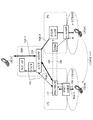
図1は3GPPの移動通信ネットワーク構成の一部を示す。図1に示す移動通信ネットワークは、e−UTRAN(evolved Universal Terrestrial Radio Access Network)、e−UTRANの基地局(e−nodeB)、PS網、CS網、CS網の基地局サブシステム、及びIMS(IP Multimedia Subsystem)から構成される。 FIG. 1 shows a part of a 3GPP mobile communication network configuration. 1 includes an e-UTRAN (evolved Universal Terrestrial Radio Access Network), an e-UTRAN base station (e-nodeB), a PS network, a CS network, a CS network base station subsystem, and an IMS ( IP Multimedia Subsystem).
具体的には、図1において、e−UTRANは、VoLTEサービスを提供可能な無線アクセス網である。PS網は、VoLTEサービスを提供し、P−GW(Packet Data Network Gateway)、S−GW(Serving Gateway)及びMME(Mobility Management Entity)から構成される。CS網は、MSC(Mobile Switching Center)、MGW(Media GateWay)から構成される。CS網の基地局サブシステムは、RNC(Radio Network Controller)及びnodeBから構成される。IMSは、呼制御等を行い、CSCF(Call Session Control Function)及びSCC AS(Service Centralization and Continuity Application Server)から構成される。なお、図1及び図2では、MSCとMGWとを一つのノード(MSC/MGW110)として表しているが、これらは別々のノードとして表してもよい。 Specifically, in FIG. 1, e-UTRAN is a radio access network capable of providing a VoLTE service. The PS network provides a VoLTE service and includes a P-GW (Packet Data Network Gateway), an S-GW (Serving Gateway), and an MME (Mobility Management Entity). The CS network includes an MSC (Mobile Switching Center) and an MGW (Media Gate Way). The base station subsystem of the CS network is composed of RNC (Radio Network Controller) and nodeB. The IMS performs call control and the like, and includes a CSCF (Call Session Control Function) and an SCC AS (Service Centralization and Continuity Application Server). In FIG. 1 and FIG. 2, MSC and MGW are represented as one node (MSC / MGW110), but they may be represented as separate nodes.
図1において、移動通信端末(UE:User Equipment)であるUE100及びUE102は、最初PS網にそれぞれ接続されているとする(ただし、UE102側の無線アクセス網、基地局及びPS網は図示せず)。つまり、UE100とUE102とでVoLTE通話が行われているとする。このとき、通話の途中でUE100がCS網にハンドオーバ(HO:Hand Over)することを仮定する。 In FIG. 1, it is assumed that UE 100 and UE 102 which are mobile communication terminals (UE: User Equipment) are initially connected to the PS network (however, the radio access network, base station and PS network on the UE 102 side are not shown). ). That is, it is assumed that a VoLTE call is performed between the UE 100 and the UE 102. At this time, it is assumed that the UE 100 is handed over (HO: Hand Over) to the CS network during the call.
図1の実線で示されたPath A、Path B及びPath Cは、通話データが通る経路を示す。また、図1の破線で示された200、202、204及び206は、SRVCCハンドオーバ処理におけるシグナリングが通る経路を示す。
Path A, Path B, and Path C indicated by solid lines in FIG. 1 indicate paths through which call data passes. Further,
図2は、SRVCCハンドオーバ処理の動作を示すシーケンスチャートである。UE100及びUE102は最初PS網(e−UTRAN)にそれぞれ接続されており、UE100とUE102との間の通話データはPath Aを通って送受信されている。UE100がe−UTRANのカバーエリアから遠ざかろうとすると、e−nodeBは、これを検知し、MME、MSC/MGW110経由でRNC/nodeBとの間でシグナリングをやり取りする(図1に示すシグナリング200。図2に示すステップ(以下、「ST」という)200)。ST200において、nodeBとMSC/MGW110との間にCS網でのデータ経路が準備され、準備が終わると、MMEからe−nodeB経由で、UE100に対し、UTRAN(CS網)側にハンドオーバするよう命令が出される。
FIG. 2 is a sequence chart showing the operation of the SRVCC handover process. The UE 100 and the UE 102 are initially connected to the PS network (e-UTRAN), respectively, and call data between the UE 100 and the UE 102 is transmitted and received through the Path A. When the UE 100 tries to move away from the coverage area of the e-UTRAN, the e-nodeB detects this and exchanges signaling with the RNC / nodeB via the MME and the MSC / MGW 110 (the
ST200の処理と同時に、MSC/MGW110は、CSCF/SCC AS経由でUE102とシグナリングをやり取りする(図1に示すシグナリング202。図2に示すST202)。これにより、UE102の通話データの送受信先を、UE100からMSC/MGW110に切り替えるよう命令が出され、Path Bが確立される。
Simultaneously with the processing of ST200, MSC /
UE100は、UTRANにハンドオーバした後、RNC/nodeB経由でMSC/MGW110とシグナリングをやり取りする(図1に示すシグナリング204。図2に示すST204)。これにより、Path Cが確立される。 After handing over to UTRAN, UE 100 exchanges signaling with MSC / MGW 110 via RNC / nodeB (signaling 204 shown in FIG. 1 and ST204 shown in FIG. 2). Thereby, Path C is established.
Path C確立後、MSC/MGW110は、MME経由でP−GW/S−GWとシグナリングをやり取りする(図1に示すシグナリング206。図2に示すST206)。これにより、Path Aは削除される。
After establishing Path C, MSC /
以上、SRVCCハンドオーバの動作について説明した。 The operation of SRVCC handover has been described above.
また、SRVCCを改良し、データ経路切替にかかる時間を短縮する方式として、非特許文献3に記載の、ATCF(Access Transfer Control Function)エンハンスメントを用いたSRVCC方式(eSRVCC:enhanced-SRVCC)がある。このeSRVCCの動作の一例について、以下、図3及び図4を用いて説明する。 As a method for improving SRVCC and reducing the time required for data path switching, there is a SRVCC method (eSRVCC: enhanced-SRVCC) described in Non-Patent Document 3 using an ATCF (Access Transfer Control Function) enhancement. An example of the operation of this eSRVCC will be described below with reference to FIGS.
図3は、eSRVCCを可能にする、3GPPの移動通信ネットワーク構成の一部を示す。図3に示す移動通信ネットワークは、図1と同様、e−UTRAN、e−nodeB、PS網、CS網、CS網の基地局サブシステム、及びIMSから構成される。ここでIMSには、CSCF及びSCC ASの他、ATCF(Access Transfer Control Function)及びATGW(Access Transfer GateWay)が存在する。なお、図3及び図4では、ATCFとATGWとを一つのノード(ATCF/ATGW320)として表しているが、これらは別々のノードとして表してもよい。 FIG. 3 shows part of a 3GPP mobile communication network configuration that enables eSRVCC. As in FIG. 1, the mobile communication network shown in FIG. 3 includes e-UTRAN, e-nodeB, PS network, CS network, CS network base station subsystem, and IMS. Here, in addition to CSCF and SCC AS, IMS includes ATCF (Access Transfer Control Function) and ATGW (Access Transfer GateWay). 3 and 4, the ATCF and ATGW are represented as one node (ATCF / ATGW 320), but they may be represented as separate nodes.
図3において、UE100及びUE102は、最初PS網にそれぞれ接続されているとする(ただし、UE102側の無線アクセス網、基地局及びPS網は図示せず)。つまり、UE100とUE102とでVoLTE通話が行われているとする。このとき、通話の途中でUE100がCS網にハンドオーバ(HO:Hand Over)することを仮定する。 In FIG. 3, it is assumed that UE 100 and UE 102 are initially connected to the PS network (however, the radio access network, base station, and PS network on UE 102 side are not shown). That is, it is assumed that a VoLTE call is performed between the UE 100 and the UE 102. At this time, it is assumed that the UE 100 is handed over (HO: Hand Over) to the CS network during the call.
図3の実線で示されたPath A、Path B、Path C及びPath Dは、通話データが通る経路を示す。また、図3の破線で示された300、302、304及び306は、eSRVCCハンドオーバ処理におけるシグナリングが通る経路を示す。 Path A, Path B, Path C, and Path D indicated by solid lines in FIG. 3 indicate paths through which call data passes. Also, 300, 302, 304, and 306 indicated by broken lines in FIG. 3 indicate paths through which signaling in the eSRVCC handover process passes.
図4は、eSRVCCハンドオーバの動作を示すシーケンスチャートである。UE100及びUE102は最初PS網(e−UTRAN)にそれぞれ接続されている。eSRVCCハンドオーバを実現するシステムでは、ATCF/ATGW320において、ATCFはIMSのシグナリング(IMSシグナリング)をアンカーし、ATGWは通話データをアンカーする。つまり、UE100とUE102との間の通話開始時において、通話開始のIMSシグナリングはATCFで中継され、ATCFがATGWでの通話データのアンカーが必要と判断した場合、通話データのアンカーポイントとしてATGWが割り当てられる。これにより、UE100とUE102との間の通話データは、Path A及びPath Bを通って送受信される。
FIG. 4 is a sequence chart showing the operation of eSRVCC handover. UE100 and UE102 are each initially connected to PS network (e-UTRAN). In the system for realizing the eSRVCC handover, in ATCF /
UE100がe−UTRANのカバーエリアから遠ざかろうとすると、e−nodeBは、これを検知し、MME、MSC/MGW110経由でRNC/nodeBとの間でシグナリングをやり取りする(図3に示すシグナリング300。図4に示すST300)。ST300において、nodeBとMSC/MGW110との間にCS網でのデータ経路が準備され、準備が終わると、MMEからe−nodeB経由で、UE100に対し、UTRAN(CS網)側にハンドオーバするよう命令が出される。 When the UE 100 tries to move away from the e-UTRAN coverage area, the e-nodeB detects this and exchanges signaling with the RNC / nodeB via the MME and the MSC / MGW 110 (signaling 300 shown in FIG. 3). ST300 shown in FIG. In ST300, a data path in the CS network is prepared between nodeB and MSC / MGW110, and when the preparation is completed, an instruction is issued from MME to hand over UE100 to UTRAN (CS network) via e-nodeB. Is issued.
ST300の処理と同時に、MSC/MGW110は、ATCFにシグナリングを送る。これによりATCFからATGWに経路切替の指示が出され、ATGWの通話データ送受信先がUE100からMSC/MGW110に切り替わる(図3に示すシグナリング302。図4に示すST302)。すなわち、Path Cが確立される。また、ATGWへの経路切替処理が完了すると、ATCFは、SCC−ASに通知シグナリングを送信する(図3に示すシグナリング302。図4に示すST302)。
Simultaneously with the processing of ST300, MSC / MGW110 sends signaling to ATCF. As a result, a route switching instruction is issued from the ATCF to the ATGW, and the call data transmission / reception destination of the ATGW is switched from the
UE100は、UTRANにハンドオーバした後、RNC/nodeB経由でMSC/MGW110とシグナリングをやり取りする(図3に示すシグナリング304。図4に示すST304)。これにより、Path Dが確立される。 After handing over to UTRAN, UE 100 exchanges signaling with MSC / MGW 110 via RNC / nodeB (signaling 304 shown in FIG. 3 and ST304 shown in FIG. 4). Thereby, Path D is established.
Path D確立後、MSC/MGW110は、MME経由でP−GW/S−GWとシグナリングをやり取りする(図3に示すシグナリング306。図4に示すST306)。これにより、Path Bは削除される。
After establishing Path D, MSC /
以上、eSRVCCハンドオーバの動作について説明した。 The operation of eSRVCC handover has been described above.
CS網で利用される音声コーデックとして、広帯域(WB:Wideband)コーデックであるAMR−WB(Adaptive Multi-Rate Wideband)コーデックがある。AMR−WBは、パケット交換方式で利用可能であるため、PS網(VoLTE)での利用も考えられている。 As an audio codec used in the CS network, there is an AMR-WB (Adaptive Multi-Rate Wideband) codec which is a wideband (WB) codec. Since AMR-WB can be used in a packet switching system, use in the PS network (VoLTE) is also considered.
また、例えば、非特許文献4に記載のEVS(Enhanced Voice Service)のように、PS網(VoLTE)で利用される、AMR−WB以外の他のコーデックとして、AMR−WB互換モードをサポートするコーデックもある。AMR−WB互換モードは、通常AMR−WBコーデックをサポートするレガシー端末との間でAMR−WBコーデックとして使用されることを想定している。このため、PS網(VoLTE)で当該コーデックが利用される際には、非特許文献2に記載のAMR−WBコーデックのRTPペイロードフォーマットが用いられることが考えられる。 Also, for example, a codec that supports an AMR-WB compatible mode as a codec other than AMR-WB used in the PS network (VoLTE), such as EVS (Enhanced Voice Service) described in Non-Patent Document 4. There is also. The AMR-WB compatible mode is assumed to be used as an AMR-WB codec with a legacy terminal that normally supports the AMR-WB codec. For this reason, when the codec is used in the PS network (VoLTE), it is conceivable that the RTP payload format of the AMR-WB codec described in Non-Patent Document 2 is used.
なお、従来技術において、狭帯域(NB:Narrowband)コーデックとは、8kHzでサンプリングされたデジタル音響信号の符号化及び復号処理を行うコーデックである。なお、狭帯域コーデックでは、一般的に300Hz〜3.4kHzの周波数帯域を有するが、周波数帯域はこれに限らず0〜4kHzの範囲内であればよい。また、広帯域コーデックとは、16kHzでサンプリングされたデジタル音響信号の符号化及び復号処理を行うコーデックである。なお、広帯域コーデックでは、一般的に50Hz〜7kHzの周波数帯域を有するが、周波数帯域はこれに限らず0〜8kHzの範囲内であればよい。また、超広帯域(SWB:Super Wideband)コーデックとは、32kHzでサンプリングされたデジタル音響信号の符号化及び復号処理を行うコーデックである。超広帯域コーデックでは、一般的に50Hz〜14kHzの周波数帯域を有するが、周波数帯域はこれに限らず0〜16kHzの範囲内であればこれに限定されない。 In the prior art, a narrowband (NB) codec is a codec that performs encoding and decoding processing of a digital audio signal sampled at 8 kHz. A narrowband codec generally has a frequency band of 300 Hz to 3.4 kHz, but the frequency band is not limited to this and may be in the range of 0 to 4 kHz. The wideband codec is a codec that performs encoding and decoding processing of a digital audio signal sampled at 16 kHz. A wideband codec generally has a frequency band of 50 Hz to 7 kHz, but the frequency band is not limited to this and may be in the range of 0 to 8 kHz. A super wideband (SWB) codec is a codec that performs encoding and decoding processing of a digital audio signal sampled at 32 kHz. An ultra-wideband codec generally has a frequency band of 50 Hz to 14 kHz, but the frequency band is not limited to this and is not limited to this as long as it is within a range of 0 to 16 kHz.
図1又は図3において、UE100がPS網からCS網にハンドオーバした際、PS網で使用していたコーデックがCS網でサポートされていない場合には、UE100で使用されるコーデックは、CS網でサポートされているコーデックに変更される。UE100のコーデックに変更が生じた場合、UE100とUE102との通話継続を可能にするためには、次の2つの方法が考えられる。1つ目の方法は、MSC/MGW又はATCF/ATGWにおいてトランスコーディングを行う方法である。2つ目の方法は、UE102で使用されるコーデックをUE100の変更後のコーデックと同じものに変更する方法である。
1 or 3, when the
前者のトランスコーディングを行う方法では、トランスコーディングによる通話品質の劣化が生じてしまう。 In the former method of transcoding, the speech quality is deteriorated by transcoding.
一方、後者のコーデックを変更する方法では、トランスコーディングを行う方法のような通話品質の劣化は生じないものの、UE102のコーデックを変更するためのシグナリングに時間がかかり、通話が途切れる時間が長くなるので好ましくない。更に、eSRVCCハンドオーバでは、UE100のハンドオーバの際の経路切替のためのシグナリングがATCFで終端するため、UE102のコーデックを変更するためのシグナリングを送ることすらできない。すなわち、eSRVCCハンドオーバでは、既存のシグナリングを使ってUE102のコーデックを変更することができない。
On the other hand, the latter method of changing the codec does not cause deterioration in call quality unlike the method of transcoding, but it takes time for signaling to change the codec of the UE 102, and the call is interrupted for a long time. It is not preferable. Furthermore, in eSRVCC handover, since the signaling for path switching at the time of handover of the
本発明の目的は、通信中の端末の一方が使用していたコーデックが変更される場合でも、通話品質の劣化を生じさせることなく、かつ、通話が途切れる時間を抑えて通信を継続することができるネットワークノード及び通信方法を提供することである。 An object of the present invention is to continue communication without causing degradation in call quality and suppressing the time during which a call is interrupted even when the codec used by one of the communicating terminals is changed. It is to provide a network node and a communication method that can be used.
本発明の一態様に係るネットワークノードは、第1のコーデックをサポートする第1の通信端末と、第2の通信端末と通信を行う、ネットワークノードであって、前記第1のコーデックは、前記第1のコーデックに対してレガシータイプである第2のコーデックとの互換性を有する互換モード及び、前記第2のコーデックと互換性を有さない非互換モードをサポートするコーデックであり、前記第1の通信端末及び前記第2の通信端末により、通信開始時のネゴシエーションセッションにおいて、前記第1の通信端末及び前記第2の通信端末との通信で利用するコーデックとして、前記第1のコーデックの前記非互換モードが折衝され、前記第1の通信端末と前記第2の通信端末との通信中に、いずれか一方の通信端末のコーデックが変更になったことを検出する検出部と、前記検出部において、前記第1の通信端末のコーデックが前記折衝された前記非互換モードから前記互換モード、または前記第2のコーデックに切替えたことを検出した場合、前記第2の通信端末に対し、前記互換モードへの切替えを要求するシグナリングを送信する送信部と、を備える。 A network node according to an aspect of the present invention is a network node that communicates with a first communication terminal that supports a first codec and a second communication terminal, wherein the first codec A codec that supports a compatible mode compatible with a second codec that is a legacy type with respect to one codec and an incompatible mode that is not compatible with the second codec. The incompatibility of the first codec as a codec used in communication with the first communication terminal and the second communication terminal in a negotiation session at the start of communication by the communication terminal and the second communication terminal The mode is negotiated, and the codec of one of the communication terminals is changed during communication between the first communication terminal and the second communication terminal. A detecting unit for detecting that the codec of the first communication terminal is switched from the negotiated incompatible mode to the compatible mode or the second codec in the detecting unit; A transmission unit that transmits signaling for requesting switching to the compatible mode to the second communication terminal.
本発明の一態様に係る通信方法は、第1のコーデックをサポートする第1の通信端末と、第2の通信端末と通信を行う、ネットワークノードにおける通信方法であって、前記第1のコーデックは、前記第1のコーデックに対してレガシータイプである第2のコーデックとの互換性を有する互換モード及び、前記第2のコーデックと互換性を有さない非互換モードをサポートするコーデックであり、前記第1の通信端末及び前記第2の通信端末により、通信開始時のネゴシエーションセッションにおいて、前記第1の通信端末及び前記第2の通信端末との通信で利用するコーデックとして、前記第1のコーデックの前記非互換モードが折衝され、前記第1の通信端末と前記第2の通信端末との通信中に、いずれか一方の通信端末のコーデックが変更になったことを検出し、前記第1の通信端末のコーデックが前記折衝された前記非互換モードから前記互換モード、または前記第2のコーデックに切替えたことを検出した場合、前記第2の通信端末に対し、前記互換モードへの切替えを要求するシグナリングを送信する。 A communication method according to an aspect of the present invention is a communication method in a network node that performs communication with a first communication terminal that supports a first codec and a second communication terminal, wherein the first codec is A compatible mode that is compatible with a second codec that is a legacy type with respect to the first codec, and a non-compatible mode that is not compatible with the second codec, As a codec used in communication with the first communication terminal and the second communication terminal in a negotiation session at the start of communication by the first communication terminal and the second communication terminal, the codec of the first codec When the incompatible mode is negotiated and the communication between the first communication terminal and the second communication terminal is performed, the codec of one of the communication terminals is If it is detected that the codec of the first communication terminal is switched from the negotiated incompatible mode to the compatible mode or the second codec, the second communication is performed. Signaling for requesting switching to the compatible mode is transmitted to the terminal.
本発明によれば、通信中の端末の一方が使用していたコーデックが変更される場合でも、通話品質の劣化を生じさせることなく、かつ、通話が途切れる時間を抑えて通信を継続することができる。 According to the present invention, even when the codec used by one of the communicating terminals is changed, the communication can be continued without causing deterioration of the call quality and suppressing the time during which the call is interrupted. it can.
以下、本発明の各実施の形態について、図面を参照して詳細に説明する。 Hereinafter, embodiments of the present invention will be described in detail with reference to the drawings.
以下の説明では、「帯域幅」とはコーデックの入出力となる信号の帯域幅のことを指す。 In the following description, “bandwidth” refers to the bandwidth of a signal that is input / output of a codec.
また、以下の説明では、PS網及びCS網の双方において利用可能なコーデックを「コーデックA」と表す。コーデックAは、専用のペイロードフォーマットを持つ。コーデックAは、例えば、AMR−WB又はAMR−NBである。 In the following description, a codec that can be used in both the PS network and the CS network is represented as “codec A”. Codec A has a dedicated payload format. The codec A is, for example, AMR-WB or AMR-NB.
また、PS網において利用可能なコーデックを「コーデックB」と表す。コーデックBは、コーデックAに対する、非互換モード(コーデックA非互換モード)と互換モード(コーデックA互換モード)とを有する。ただし、コーデックBはCS網で利用されてもよい。コーデックBは、例えば、EVS又は非特許文献7に記載のG.718である。 Further, a codec that can be used in the PS network is represented as “codec B”. Codec B has an incompatible mode (codec A incompatible mode) and a compatible mode (codec A compatible mode) for codec A. However, codec B may be used in the CS network. Codec B is, for example, GVS described in EVS or Non-Patent Document 7. 718.
(実施の形態1)
図5は、コーデックBのペイロードフォーマット(RTPペイロードフォーマット)の一例を示す。図5に示すように、ペイロードフォーマットは、データ部とヘッダ部とにより構成される。データ部にはエンコーダによりエンコードされたデータが含まれ、ヘッダ部にはデコーダがデータ部のデータをデコードするために必要な情報が含まれる。
(Embodiment 1)
FIG. 5 shows an example of the payload format (RTP payload format) of Codec B. As shown in FIG. 5, the payload format includes a data part and a header part. The data portion includes data encoded by the encoder, and the header portion includes information necessary for the decoder to decode the data in the data portion.
本実施の形態におけるコーデックBのペイロードフォーマットは、データ部にコーデックA非互換モードのデータが含まれるのか、コーデックA互換モードのデータが含まれるのかをペイロード受信側で識別できる構成を持つ。例えば、図5に示すように、ヘッダ部には、「コーデックタイプ」フィールドと「ビットレート」フィールドが含まれる。「コーデックタイプ」には、コーデックA非互換モード又はコーデックA互換モードのいずれであるかを示す情報が含まれる。「ビットレート」には、コーデックA非互換モード、コーデックA互換モードのそれぞれでサポートしているビットレートのうち、どのビットレートでエンコードされたデータであるかを示す情報が含まれる。 The payload format of codec B in the present embodiment has a configuration that allows the payload receiving side to identify whether the data portion includes codec A incompatible mode data or codec A compatible mode data. For example, as shown in FIG. 5, the header portion includes a “codec type” field and a “bit rate” field. The “codec type” includes information indicating whether the codec A incompatible mode or the codec A compatible mode. The “bit rate” includes information indicating at which bit rate the encoded data is the bit rate supported in each of the codec A incompatible mode and the codec A compatible mode.
また、図5に示すように、上記フィールドの他に、ペイロード受信側である相手端末に対してコーデックタイプ又はビットレートの切替要求指示を行うフィールド(「コーデックタイプ・ビットレート切替要求」フィールド)を含んでもよい。なお、このフィールドは、フレーム毎に含まれる必要はなく、必要な時にだけ含まれてもよい。 Further, as shown in FIG. 5, in addition to the above fields, a field (“codec type / bit rate switching request” field) for instructing a partner terminal on the payload receiving side to switch the codec type or bit rate is provided. May be included. This field need not be included for each frame, and may be included only when necessary.
なお、図5に示すコーデックBのペイロードフォーマットにおいて、データ部にコーデックA非互換モードのデータが含まれるのか、コーデックA互換モードのデータが含まれるのかをペイロード受信側で識別できる構成を取るためのフィールド(「コーデックタイプ」フィールド、「ビットレート」フィールド)、及び、相手端末に対して、コーデックタイプ又はビットレートの切替要求指示を行うフィールド(「コーデックタイプ・ビットレート切替要求」フィールド)を、ヘッダ部に明示的に含める方法を示した。しかし、必ずしも図5に示す方法でなくてもよい。また、図5に示すペイロードフォーマットの一例では、ペイロードフォーマットがヘッダ部とデータ部とから構成される例を示したが、ヘッダ部が無くてもペイロードを受け取った受信側の端末が正しくデータをデコードできる場合には、ペイロードフォーマットにおいてヘッダ部は無くてもよい。 Note that in the payload format of codec B shown in FIG. 5, a configuration is adopted in which the payload receiving side can identify whether the data part includes data in codec A incompatible mode or data in codec A compatible mode. Fields ("codec type" field, "bit rate" field) and fields for instructing the other terminal to switch codec type or bit rate ("codec type / bit rate switching request" field) We showed how to include it explicitly in the section. However, the method shown in FIG. In the example of the payload format shown in FIG. 5, an example in which the payload format is composed of a header part and a data part is shown. However, even if there is no header part, the receiving terminal that has received the payload correctly decodes the data. If possible, there may be no header part in the payload format.
また、コーデックBのペイロードフォーマットは図5に示す一例に限らず、例えば、非特許文献7に記載のG.718のペイロードフォーマットのように、各レイヤの組み合わせ(ビットレート相当)が、別々の値として記述されていてもよい。 The payload format of codec B is not limited to the example shown in FIG. Like the payload format of 718, the combination of each layer (corresponding to the bit rate) may be described as separate values.
次に、図6は、通話開始時のセッション折衝において端末間でやり取りされる、SDP(Session Description Protocol)オファー及びSDPアンサーの一例を示す。 Next, FIG. 6 shows an example of an SDP (Session Description Protocol) offer and an SDP answer exchanged between terminals in session negotiation at the start of a call.
ここでは、通話を行う双方のUEがコーデックBをサポートしており、かつ、通話開始時に共にPS網に接続していると仮定する。 Here, it is assumed that both UEs that make a call support codec B, and both are connected to the PS network at the start of the call.
図6に示すように、コーデックBをサポートするUEは、コーデックAをサポートしていない場合においても、コーデックA及びコーデックBをSDPオファーに記述する。これは、相手端末が、コーデックAをサポートしているがコーデックBをサポートしていなかった場合、コーデック折衝においてコーデックAを選択し、コーデックBのコーデックA互換モードをコーデックAのRTPペイロードフォーマットを用いて使用する事を可能にするためである。図6では、SDPオファーを受け取ったUEは、コーデックBを選択し、選択したコーデックBをSDPアンサーに記述する。 As shown in FIG. 6, a UE that supports codec B describes codec A and codec B in the SDP offer even when codec A is not supported. This is because when the other terminal supports codec A but does not support codec B, codec A is selected in codec negotiation, and codec A compatibility mode of codec B is used as the RTP payload format of codec A. This is to enable use. In FIG. 6, the UE that has received the SDP offer selects codec B, and describes the selected codec B in the SDP answer.
なお、このSDPオファー及びSDPアンサーの中に、コーデックBを選択した場合に優先されるモード(コーデックA非互換モード又はコーデックA互換モード、ビットレート、帯域幅等)が記述されていてもよい。優先されるモードは、通信サービスを行うオペレータによって予め決められ、ソフトウェアの形式等でUEに組み込まれていてもよい。本実施の形態では、コーデックBが選択された場合、コーデックA非互換モードを優先モードとして使用すると仮定する。 In this SDP offer and SDP answer, a mode (Codec A incompatible mode or Codec A compatible mode, bit rate, bandwidth, etc.) that is prioritized when Codec B is selected may be described. The mode to be prioritized may be determined in advance by an operator who performs a communication service and may be incorporated in the UE in the form of software or the like. In the present embodiment, it is assumed that when codec B is selected, codec A incompatible mode is used as the priority mode.
次に、本実施の形態に係る移動通信ネットワーク(図1)について説明する。 Next, the mobile communication network (FIG. 1) according to the present embodiment will be described.
まず、図1に示すUE100,102について説明する。
First, the
図7は、本実施の形態に係るUE100,102(端末)の構成を示すブロック図である。UE100,102は、受信部700、送信部702、コーデック折衝部704、RTPペイロード解析部706、RTPペイロード生成部708及びコーデック通知部710を有して構成される。
FIG. 7 is a block diagram showing a configuration of
図7に示すUE100,102において、受信部700は、通信データ(RTPペイロードを含む)及びシグナリング等を受信する。例えば、受信部700は、MSC/MGW110から送信されるRTPペイロード(例えば図5参照)を受信すると、受信したRTPペイロードをRTPペイロード解析部706に出力する。
In
送信部702は、通信データ(RTPペイロードを含む)及びシグナリング等を送信する。
The
コーデック折衝部704は、端末(UE100,UE102)間の通信に使用するコーデックを折衝する。具体的には、コーデック折衝部704は、SDPオファー又はSDPアンサーを作成し(例えば図6参照)、コーデック折衝を行う。この際、コーデック折衝部704は、SDPオファーを作成する際、前述の通り、端末がコーデックBをサポートするがコーデックAをサポートしていない場合においても、図6のようにコーデックAをSDPオファーに含める。またコーデック折衝部704は、折衝においてコーデックBが選択された場合、前述のようにSDPオファー及びアンサーの中に記述された情報、又はあらかじめソフトウェア等に組み込まれた情報に従い、優先されるモード(コーデックA非互換モード又はコーデックA互換モード、ビットレート、帯域幅等)を選択し、RTPペイロード生成部708に出力する。
The
RTPペイロード解析部706は、受信部700から受け取ったRTPペイロードのヘッダ部を解析して、RTPペイロードのデータ部に含まれるデータに関する情報(例えば、コーデックタイプ、ビットレート等)を特定する。RTPペイロード解析部706は、特定した情報及びデータ部に含まれるデータをデコーダ(図示せず)に出力する。また、RTPペイロード解析部706は、受信部700から受け取ったRTPペイロードに「コーデックタイプ・ビットレート切替要求」の指示が含まれる場合には、当該指示をエンコーダ(図示せず)及びRTPペイロード生成部708に出力する。エンコーダは、RTPペイロード解析部706からの情報及び指示に基づいてデータをエンコードする。
The RTP
RTPペイロード生成部708は、エンコーダから受け取ったデータ及びコーデック折衝部704から受け取った当該データに関する情報(例えば、コーデックタイプ、ビットレート等)を含むRTPペイロード(例えば、図5参照)を生成する。この際、RTPペイロード生成部708は、RTPペイロード解析部706から、「コーデックタイプ・ビットレート切替要求」の指示が入力される場合には、当該指示に基づいてRTPペイロードを生成する。生成されたRTPペイロードは、送信部702を介して送信される。
The RTP
コーデック通知部710は、自機がPS網からCS網へハンドオーバする際、自機がPS網で使用しているコーデックをPS網のネットワークノード(例えばMME等)に通知する。通知されたコーデックは、PS網のネットワークノード(MME)を介して、MSC/MGW110に通知される。
When the own device hands over from the PS network to the CS network, the
次いで、図1に示すMSC/MGW110について説明する。図8は、本実施の形態に係るMSC/MGW110(ネットワークノード)の構成を示すブロック図である。MSC/MGW110は、受信部800、送信部802、コーデック検出部804、コーデック折衝部806、RTPペイロード生成部808及びRTPペイロード解析部810を有して構成される。
Next, the MSC /
図8に示すMSC/MGW110において、受信部800は、通信データ(RTPペイロードを含む)、シグナリング等を受信する。例えば、受信部800は、UE102から送信されるRTPペイロード(例えば図5参照)を受信すると、受信したRTPペイロードをRTPペイロード解析部810に出力する。
In MSC /
送信部802は、通信データ(RTPペイロードを含む)、シグナリング等を送信する。
The
コーデック検出部804は、PS網からCS網にハンドオーバした端末(図1ではUE100)がCS網で使用するコーデックを検出する。また、コーデック検出部804は、PS網からCS網にハンドオーバした端末(図1ではUE100)がPS網で使用していたコーデックを検出する。端末(UE100)がPS網で使用していたコーデックを検出する方法としては、非特許文献5に開示されているように、UE100(コーデック通知部710)がCS網にハンドオーバする際にPS網のネットワークノード(MMEなど)から通知される方法でもよい。または、端末(UE100)がPS網で使用していたコーデックを検出する方法としては、例えば、SCC AS等の他のネットワークノードから取得する方法でもよい。また、端末(UE100)がCS網で使用しているコーデックを検出する方法としては、UE100がCS網にハンドオーバした際に、UE100とCS網内のネットワークノード(RNC及びMSC/MGW110)との間で送受信されるシグナリングにより折衝された情報を利用する方法がある。コーデック検出部804は、コーデックの検出結果をRTPペイロード生成部808に出力する。
The
コーデック折衝部806は、例えば、RTPペイロード生成部808からの指示に従って、UEとの間で使用するコーデックを折衝する。例えば、コーデック折衝部806は、PS網からCS網にハンドオーバした端末(図1ではUE100)の通信相手である端末(図1ではUE102)との間で使用するコーデックを折衝(再折衝)する。
For example, the
RTPペイロード生成部808は、コーデック検出部804から入力されるコーデックの検出結果に基づいて、端末(図1ではUE100)から受け取ったデータを用いて、当該端末の通信相手(図1ではUE102)向けのデータ(RTPペイロード)を生成する。例えば、RTPペイロード生成部808は、PS網からCS網へハンドオーバした端末がCS網で使用するコーデックがコーデックAであり、当該端末がPS網で使用していたコーデックがコーデックBである場合、当該端末から受け取ったデータ(コーデックAのデータ)のコーデックを、コーデックBのコーデックA互換モードに切り替える。すなわち、MSC/MGW110は、当該端末から受け取ったコーデックAのデータを、コーデックBのRTPペイロードフォーマット(図5参照)を用いて、コーデックBのコーデックA互換モードとして、送信部802を介して送信する。
Based on the codec detection result input from the
また、コーデック検出部804から入力されるコーデックの検出結果が上記以外の場合には、RTPペイロード生成部808は、例えば、コーデック折衝部806に対して、受け取ったデータの送信先である通信相手(図1ではUE102)との間のコーデックの折衝(再折衝)を指示する。そして、RTPペイロード生成部808は、ハンドオーバした端末から受け取った通信データを折衝結果に基づいて必要であればトランスコーディングし、折衝結果に基づくコーデックモードに切り替える。コーデック切替後のデータ(生成されたRTPペイロード)は、送信部802を介して送信される。
In addition, when the codec detection result input from the
RTPペイロード解析部810は、端末(UE102)から送信されるRTPペイロードのヘッダ部を解析して、RTPペイロードのデータ部に含まれるデータに関する情報(例えば、コーデックタイプ、ビットレート等)を特定する。RTPペイロード解析部810は、特定した情報をコーデック検出部804に出力する。
The RTP
次いで、図9を用いて、MSC/MGW110(図8)におけるコーデック処理の詳細について説明する。なお、ここでは、図1に示すように、UE100とUE102とが共にPS網に接続されて通話を行っている途中に、UE100がPS網からCS網にハンドオーバした場合について説明する。すなわち、MSC/MGW110は、PS網において通信を行う2つの端末(UE100,102)のうち一方のUE100がCS網にハンドオーバした際に、2つの端末間のデータを転送するネットワークノードである。
Next, details of the codec processing in the MSC / MGW 110 (FIG. 8) will be described with reference to FIG. Here, as shown in FIG. 1, a case will be described in which
図9に示すST900において、RTPペイロード生成部808は、コーデック検出部804での検出結果に基づいて、UE100がCS網で使用するコーデックがコーデックAであるか否かを判断する。
In ST900 shown in FIG. 9, RTP
UE100がCS網で使用するコーデックがコーデックAである場合(ST900:YES)、ST902において、RTPペイロード生成部808は、コーデック検出部804での検出結果に基づいて、UE100がPS網で(ハンドオーバ前に)使用していたコーデックがコーデックBであるか否かを判断する。
When the codec used by the
UE100がPS網で使用していたコーデックがコーデックBである場合(ST902:YES)、ST904において、RTPペイロード生成部808は、UE100から送信されたデータ(コーデックA)のコーデックを、コーデックBのコーデックA互換モードに切り替える。つまり、RTPペイロード生成部808は、UE100から送信されたコーデックAのデータを、コーデックBのRTPペイロードフォーマットを用いてコーデックBのコーデックA互換モードとして、送信部802を介してUE102へ送信する。
When the codec used by the
これにより、コーデックBを使用するUE102は、MSC/MGW110からUE102へ送信されるデータを、コーデックBのデータ(コーデックBのコーデックA互換モード)として扱うことが可能となる。
Thereby, the UE 102 using the codec B can handle data transmitted from the MSC /
一方、UE100がCS網で使用するコーデックがコーデックAではない場合(ST900:NO)、又は、UE100がPS網で使用していたコーデックがコーデックBではない場合(ST902:NO)、ST906において、コーデック折衝部806は、UE102との間でセッション再折衝を行って、コーデックを決定する。そして、RTPペイロード生成部808は、決定されたコーデックのRTPペイロードを生成する。
On the other hand, if the codec used by the
または、ST906において、MSC/MGW110は、UE100から送信されたデータに対してトランスコーディングを行い、トランスコーディング後のデータ(UE102向けのデータ)をUE102に送信してもよい。 Or in ST906, MSC / MGW110 may transcode with respect to the data transmitted from UE100, and may transmit the data after transcoding (data for UE102) to UE102.
このようにして、MSC/MGW110は、一方のUEのコーデックの変更が検出された場合、当該UEの変更後のコーデックと、当該UEの変更前のコーデックとに基づいて、他方のUE向けデータのコーデックを切り替えることが可能であるか否かを判断する。
In this way, when a change in the codec of one UE is detected, the MSC /
次に、本実施の形態におけるUE100,102(図7)、及び、MSC/MGW110(図8)の動作の一例について説明する。
Next, an example of operations of
以下の説明では、図1及び図2において、UE100及びUE102の双方ともにPS網に接続され、通話を開始する。ここでは、UE100からUE102へ発呼を行うと仮定する。
In the following description, in FIGS. 1 and 2, both the
通話開始の際、UE100とUE102との間で使用するコーデックの折衝が行われる。例えば、UE100(コーデック折衝部704)は、SDPオファー(例えば図6参照)を生成し、UE102に送信する。これに対して、UE102(コーデック折衝部704)は、SDPアンサー(例えば、図6参照。図6ではコーデックBを選択)を生成し、UE100に送信する。この通話開始に伴う一例の動作が完了すると、UE100,102は、コーデックBのコーデックA非互換モード(コーデックBを選択した場合に優先されるモード)を用いて通話を行う(図2:Speech Session over PS)。
When a call is started, a codec used between the
次いで、図1に示すように、UE100がPS網からCS網へハンドオーバする(図2に示すST200及びST204)。ここでは、UE100がCS網で使用するコーデックをコーデックAとする。
Next, as shown in FIG. 1,
UE100のハンドオーバ処理と同時に、MSC/MGW110(コーデック検出部804)は、UE100がCS網にハンドオーバした際に使用するコーデックを検出する。また、MSC/MGW110(コーデック検出部804)は、UE100がPS網で使用していたコーデックを検出する。上述したように、MSC/MGW110は、UE100がCS網で使用するコーデックがコーデックAであり、UE100がPS網で使用していたコーデックがコーデックBであることを検出する(つまり、図9に示すST900:YESかつST902:YES)。
Simultaneously with the handover process of the
この場合、MSC/MGW110(RTPペイロード生成部808)は、UE100から送信されたデータ(コーデックA)のコーデックを、コーデックBのコーデックA互換モードに切り替えることにより、UE102向けのRTPペイロードを生成する。つまり、MSC/MGW110は、UE100から送信されたコーデックAのデータを、コーデックBのRTPペイロードフォーマットを用いて、コーデックBのコーデックA互換モードとしてUE102へ送信する。
In this case, the MSC / MGW 110 (RTP payload generation unit 808) generates the RTP payload for the UE 102 by switching the codec of the data (codec A) transmitted from the
また、この際、MSC/MGW110は、RTPペイロード生成部808においてUE100から送信されるデータのコーデックが切り替えられた場合、コーデックA非互換モードからコーデックA互換モードへの切替要求を、UE100の通信相手であるUE102へ送信してもよい。例えば、MSC/MGW110(RTPペイロード生成部808)は、コーデックBのRTPペイロードフォーマット(例えば図5参照)において、コーデックA非互換モードからコーデックA互換モードへの切替指示をヘッダ部(「コーデックタイプ・ビットレート切替要求」フィールド)に含めてもよい。
At this time, when the codec of data transmitted from the
一方、UE102(RTPペイロード解析部706)は、MSC/MGW110から受け取るデータに含まれる情報(RTPペイロードのヘッダ部の情報)から、RTPペイロードのデータ部に含まれるデータがコーデックA(コーデックA互換モードとして扱うことができるコーデック)であることを判断し、当該情報及びデータをデコーダに渡す。これにより、UE102のデコーダは、受け取ったデータのコーデックがコーデックA(コーデックBのコーデックA互換モード)であると認識して、当該データをデコードする。 On the other hand, the UE 102 (RTP payload analysis unit 706) determines that the data included in the data portion of the RTP payload is codec A (codec A compatible mode) from the information included in the data received from the MSC / MGW 110 (information in the header portion of the RTP payload). And the information and data are passed to the decoder. As a result, the decoder of the UE 102 recognizes that the codec of the received data is codec A (codec A codec A compatible mode), and decodes the data.
また、UE102(例えば、RTPペイロード解析部706)は、受信したRTPペイロードに、コーデックA非互換モードからコーデックA互換モードへの切替要求が含まれている場合、当該切替要求をエンコーダ(図示せず)及びRTPペイロード生成部708に出力する。これにより、UE102は、自機から送信するデータに対してもコーデックBのコーデックA互換モードを用いることを決定する。すなわち、UE102(RTPペイロード生成部708)は、エンコーダより受け取ったコーデックA互換モードのデータを、コーデックBのペイロードフォーマットに格納して、MSC/MGW110へ送信する。
In addition, when the received RTP payload includes a switching request from the codec A incompatible mode to the codec A compatible mode, the UE 102 (for example, the RTP payload analyzing unit 706) transmits the switching request to an encoder (not shown). ) And the RTP
このように、本実施の形態では、MSC/MGW110において、コーデック検出部804は、UE100がPS網で使用していたコーデック、及び、UE100がCS網で使用するコーデックを検出し、RTPペイロード生成部808は、UE100がPS網で使用していたコーデックが、UE100がCS網で使用するコーデックとの間の互換モードを有するコーデックである場合、UE100から送信されるデータのコーデックを、UE100がPS網で使用していたコーデックの互換モードに切り替えることにより、UE102向けのデータを生成する。すなわち、MSC/MGW110は、UE100がPS網で使用していたコーデックが、UE100がCS網で使用するコーデックとの間の互換モードを有するコーデックである場合、UE100から送信されるコーデックAのデータを、コーデックBのRTPペイロードフォーマットを用いてコーデックA互換モードで送信する。これにより、コーデックBを使用するUE102は、自機のコーデックを変更することなく、UE100からのデータを受け取ることができる。
As described above, in the present embodiment, in the MSC /
つまり、MSC/MGW110においてUE100からのハンドオーバ後のコーデックのデータをハンドオーバ前のコーデックの一部(ハンドオーバ前のコーデックのモードの一つ)に切り替えることで、UE100及びUE102との間では、コーデックを変更するためのシグナリングが不要となるので、通話が途切れる時間が長くなることを防ぐことができる。また、MSC/MGW110において、UE100とUE102との間のコーデックのデータの変更を行わず、コーデックのモードだけを切り替えることで、トランスコーディングのように通話品質の劣化が生じることを防ぐことができる。よって、本実施の形態によれば、通信中の端末の一方が使用していたコーデックが変更される場合でも、通話品質の劣化を生じさせることなく、かつ、通話が途切れる時間を抑えて通信を継続することができる。
In other words, the MSC /
また、本実施の形態では、MSC/MGW110は、一方の端末(UE100)から送信されるデータのコーデックが切り替えられた場合、他方の端末(UE102)が送信するデータに対する互換モードへの切替要求を、当該他方の端末(UE102)へ送信する。そして、UE102は、MSC/MGW110からのコーデックA互換モードへの切替要求に従ってコーデックA互換モードのデータを送信する。これにより、MSC/MGW110及びUE100は、UE102から送信されるデータ(コーデックBのコーデックA互換モード)をコーデックAのデータとして扱うことができる。
Further, in this embodiment, when the codec of data transmitted from one terminal (UE 100) is switched, MSC /
なお、UE102に対する、コーデックA非互換モードからコーデックA互換モードへの切替要求の通知は、必ずしもMSC/MGW110からUE102へのRTPペイロードに含まれる必要はない。例えば、当該切替要求は、図2に示すST202において、MSC/MGW110から送信されるINVITE with SDP−MGWのSDPの中に、図10に示すSDPオファーとしてUE102に通知されてもよい。また、非特許文献6に記載のRTCP−APPを用いてMSC/MGW110からUE102に上記切替要求を通知してもよい。
Note that the notification of the switching request from the codec A incompatible mode to the codec A compatible mode to the UE 102 is not necessarily included in the RTP payload from the MSC /
また、UE102がコーデックAのデータをコーデックBのRTPペイロードフォーマットで受け取った場合、UE102は、当該データの受信後、UE102からのデータ(送信データ)もコーデックA互換モードでエンコードすべきと判断してもよい。この場合、上記切替要求は不要となる。 When the UE 102 receives the codec A data in the RTP payload format of the codec B, the UE 102 determines that the data (transmission data) from the UE 102 should be encoded in the codec A compatible mode after receiving the data. Also good. In this case, the switching request is not necessary.
(実施の形態2)
図3及び図4用いて、本実施形態について説明する。なお、以下の説明では、実施の形態1と同様、UE100及びUE102は最初PS網でコーデックBを用いて通話を行っており、UE100のみがPS網からCS網にハンドオーバしたとする。また、UE100がCS網で使用するコーデックをコーデックAとする。
(Embodiment 2)
The present embodiment will be described with reference to FIGS. In the following description, as in the first embodiment, it is assumed that
図3及び図4に示すATCF/ATGW320は、単なるデータのアンカーポイントである。よって、図3及び図4に示すATCF/ATGW320がUE100からUE102へのデータ又はUE102からUE100へのデータをフォワードしている場合において、MSC/MGW110(図8)及びUE100、UE102(図7)の機能は、実施の形態1(図5〜図9)と同一である。ただし、MSC/MGW110において、UE102へのコーデック切替要求(コーデックA非互換モードからコーデックA互換モードへの切替要求)の通知の際、図2に示すST202のINVITE with SDPを使うことができない点のみが実施の形態1と異なる。
The ATCF /
また、ATCF/ATGW320が、UE100が図3に示すPath Bで使用するコーデック、及び、UE102が図3に示すPath Aで使用するコーデックの情報を保有、若しくは、他のノードから当該情報を得る手段を具備していたとする。
Further, ATCF /
この場合、MSC/MGW110のコーデック検出部804が、UE100がPS網(図3に示すPath B)で使用していたコーデックの情報を予め保有していなかった場合でも、ATCF/ATGW320は、UE100がPS網で使用していたコーデックの情報を、図4に示すST302のINVITE with SDP−MGWの返信メッセージとして、MSC/MGW110に通知することができる。
In this case, even when the
これにより、MSC/MGW110(RTPペイロード生成部808)は、UE100(ハンドオーバした端末)がPS網で使用するコーデックを即座に特定することができる。すなわち、MSC/MGW110は、UE100(ハンドオーバした端末)がPS網で使用するコーデックに基づいて、UE100から送信されるデータを、コーデックBのRTPペイロードフォーマットを用いて、コーデックA互換モードとして、UE102に即座に送信することができる。同様に、MSC/MGW110は、UE102への切替要求を、UE102に即座に送信することができる。
Thereby, MSC / MGW110 (RTP payload production | generation part 808) can pinpoint the codec which UE100 (terminal handed over) uses in PS network immediately. That is, the MSC /
よって、本実施の形態によれば、eSRVCC方式の場合でも、実施の形態1と同様、通信中の端末の一方が使用していたコーデックが変更される場合でも、通話品質の劣化を生じさせることなく、かつ、通話が途切れる時間を抑えて通信を継続することができる。 Therefore, according to the present embodiment, even in the case of the eSRVCC method, as in the first embodiment, even when the codec used by one of the communicating terminals is changed, the call quality is deteriorated. In addition, communication can be continued while suppressing the time during which the call is interrupted.
(実施の形態3)
本実施の形態では、PS網からCS網にハンドオーバした端末(図1ではUE100)がPS網に再び戻ってきた場合について説明する。
(Embodiment 3)
In the present embodiment, a case will be described in which a terminal (
図11は、本実施の形態に係るUE100,102(端末)の構成を示すブロック図である。なお、図11において、実施の形態1(図7)と同一の構成部には同一の符号を付し、説明を省略する。
FIG. 11 is a block diagram showing a configuration of
図11に示すUE100,102において、端末位置特定部1100は、自機が接続している網(PS網又はCS網)、つまり、自機の位置を特定する。これにより、自機のハンドオーバが検出可能となる。端末位置特定部1100は、自機の位置を、接続先(例えば、e−nodeB又はnodeB)の基地局IDから判断してもよく、PSコア網でのコネクション確立によって判断してもよい。
In
例えば、PS網からCS網にハンドオーバしたUE100がPS網に再び戻ってきたとする。また、UE100は、CS網でコーデックAを使用しているとする。このとき、端末位置特定部1100は、自機がPS網に接続したことを特定する。
For example, it is assumed that the
端末位置特定部1100でPS網に接続したことを特定したUE100は、UE100のコーデックを、コーデックAからコーデックB(コーデックA非互換モード)に切り替える。そして、UE100のRTPペイロード生成部708は、コーデックBのペイロードフォーマットを用いてRTPペイロードを生成する。このRTPペイロードは、送信部702を介してUE102に送信される。
The
一方、UE102のRTPペイロード解析部706は、UE100から受け取ったデータのコーデックがコーデックA互換モードからコーデックA非互換モードに切り替わったことを検知する。そして、RTPペイロード解析部706は、UE100のコーデックが切り替わったことを示す情報及びデータをデコーダに渡す。これにより、UE102のデコーダは、UE100から受け取るデータを、コーデックBのコーデックA非互換モードでデコードする。
On the other hand, the RTP
また、UE102のRTPペイロード解析部706は、受信したRTPペイロードにコーデックA互換モードからコーデックA非互換モードへの切替要求が含まれている場合、この切替要求をエンコーダ及びRTPペイロード生成部708に渡す。これにより、UE102は、自機から送信するデータに対してもコーデックBのコーデックA非互換モードを用いることを決定する。すなわち、UE102のRTPペイロード生成部708は、エンコーダより渡されたコーデックA非互換モードのデータを、コーデックBのペイロードフォーマットに格納し、UE100へ送信する。
In addition, when the received RTP payload includes a request for switching from the codec A compatible mode to the codec A incompatible mode, the RTP
なお、UE102に対する、コーデックA互換モードからコーデックA非互換モードへの切替要求の通知は、必ずしもUE100からUE102へのRTPペイロードに含まれる必要はない。例えば、非特許文献8に記載のIMSメッセージに当該切替要求を含めてもよい。また、非特許文献6に記載のRTCP−APPを用いてMSC/MGW110からUE102に当該切替要求を通知してもよい。
Note that the notification of the switching request from the codec A compatible mode to the codec A incompatible mode to the UE 102 does not necessarily need to be included in the RTP payload from the
また、UE102がコーデックA非互換モードのデータをコーデックBのRTPペイロードフォーマットで受け取った場合、UE102は、当該データの受信後、UE102にからのデータ(送信データ)もコーデックA非互換モードでエンコードすべきと判断してもよい。この場合、上記切替要求は不要となる。 When the UE 102 receives codec A incompatible mode data in the codec B RTP payload format, the UE 102 also encodes data (transmission data) from the UE 102 in the codec A incompatible mode after receiving the data. You may judge that you should. In this case, the switching request is not necessary.
こうすることで、PS網からCS網にハンドオーバした端末がPS網に再び戻ってきた場合でも、当該端末が自機の現在位置に基づいてコーデックを変更することで、通話品質の劣化を生じさせることなく、かつ、通話が途切れる時間を抑えて通信を継続することができる。 In this way, even when a terminal handed over from the PS network to the CS network returns to the PS network again, the terminal changes the codec based on the current location of the own device, thereby causing a deterioration in call quality. In addition, the communication can be continued while the time during which the call is interrupted is suppressed.
以上、本発明の各実施の形態について説明した。 The embodiments of the present invention have been described above.
なお、上記各実施の形態では、ATCF/ATGW320、MSC/MGW110、SCC AS/CSCFをそれぞれ一つのノードとして説明した。しかし、ATCF/ATGW320、MSC/MGW110、SCC AS/CSCFは、互いにインタフェースによって接続される2つ以上の別々のノードで構成されてもよい。すなわち、ATCFとATGWとの間、MSCとMGWとの間、及び、SCC ASとCSCFとの間のそれぞれにおいて、上述した機能を複数のノードに分散させてもよい。
In each of the above embodiments, ATCF /
また、上記各実施の形態では、主に音声に関するコーデックを用いて説明した。しかし、これに限らず、音楽、音響、画像等に関しても、本発明は適用可能である。 Further, in each of the above-described embodiments, the description has been made mainly using the codec related to audio. However, the present invention is not limited to this, and the present invention can also be applied to music, sound, images, and the like.
また、本発明は、上記各実施の形態に限定されず、種々変更して実施することが可能である。 The present invention is not limited to the above embodiments, and can be implemented with various modifications.
また、上記各実施の形態では、本発明をハードウェアで構成する場合を例にとって説明したが、本発明はハードウェアとの連携においてソフトウェアでも実現することも可能である。 Further, although cases have been described with the above embodiment as examples where the present invention is configured by hardware, the present invention can also be realized by software in cooperation with hardware.
また、上記各実施の形態の説明に用いた各機能ブロックは、典型的には集積回路であるLSIとして実現される。これらは個別に1チップ化されてもよいし、一部又は全てを含むように1チップ化されてもよい。ここでは、LSIとしたが、集積度の違いにより、IC、システムLSI、スーパーLSI、ウルトラLSIと呼称されることもある。 Each functional block used in the description of each of the above embodiments is typically realized as an LSI which is an integrated circuit. These may be individually made into one chip, or may be made into one chip so as to include a part or all of them. The name used here is LSI, but it may also be called IC, system LSI, super LSI, or ultra LSI depending on the degree of integration.
また、集積回路化の手法はLSIに限るものではなく、専用回路又は汎用プロセッサで実現してもよい。LSI製造後に、プログラムすることが可能なFPGA(Field Programmable Gate Array)または、LSI内部の回路セルの接続若しくは設定を再構成可能なリコンフィギュラブル/プロセッサを利用してもよい。 Further, the method of circuit integration is not limited to LSI's, and implementation using dedicated circuitry or general purpose processors is also possible. An FPGA (Field Programmable Gate Array) that can be programmed after manufacturing the LSI or a reconfigurable / processor that can reconfigure the connection or setting of circuit cells inside the LSI may be used.
さらには、半導体技術の進歩又は派生する別技術によりLSIに置き換わる集積回路化の技術が登場すれば、当然、その技術を用いて機能ブロックの集積化を行ってもよい。バイオ技術の適用等が可能性としてありえる。 Further, if integrated circuit technology comes out to replace LSI's as a result of the advancement of semiconductor technology or a derivative other technology, it is naturally also possible to carry out function block integration using this technology. Biotechnology can be applied.
2011年11月30日出願の特願2011−261617の日本出願に含まれる明細書、図面および要約書の開示内容は、すべて本願に援用される。 The disclosure of the specification, drawings, and abstract included in the Japanese application of Japanese Patent Application No. 2011-261617 filed on November 30, 2011 is incorporated herein by reference.
本発明は、通信中の通信端末の一方が利用するコーデックが変更になった場合でも通話品質の劣化を生じさせることなく、かつ、通信が途切れる時間を抑えて通信を継続することに有用である。 INDUSTRIAL APPLICABILITY The present invention is useful for continuing communication without causing deterioration in call quality even when the codec used by one of the communication terminals in communication is changed, and suppressing the time during which communication is interrupted. .
100,102 UE
200,202,204,206,300,302,304,306 シグナリング
110 MSC/MGW
320 ATCF/ATGW
700,800 受信部
702,802 送信部
704,806 コーデック折衝部
706,810 RTPペイロード解析部
708,808 RTPペイロード生成部
710 コーデック通知部
804 コーデック検出部
1100 端末位置特定部
100,102 UE
200, 202, 204, 206, 300, 302, 304, 306
320 ATCF / ATGW
700, 800
Claims (12)
前記第1のコーデックは、前記第1のコーデックに対してレガシータイプである第2のコーデックとの互換性を有する互換モード及び、前記第2のコーデックと互換性を有さない非互換モードをサポートするコーデックであり、前記第1の通信端末及び前記第2の通信端末により、通信開始時のネゴシエーションセッションにおいて、前記第1の通信端末及び前記第2の通信端末との通信で利用するコーデックとして、前記第1のコーデックの前記非互換モードが折衝され、
前記第1の通信端末と前記第2の通信端末との通信中に、いずれか一方の通信端末のコーデックが切り替わったことを検出する検出部と、
前記検出部において、前記第1の通信端末のコーデックが前記折衝された前記非互換モードから前記互換モード、または前記第2のコーデックに切替えたことを検出した場合、前記第2の通信端末に対し、前記互換モードへの切替えを要求するシグナリングを送信する送信部と、
を備えたネットワークノード。 A network node that communicates with a first communication terminal that supports a first codec and a second communication terminal,
The first codec supports a compatible mode that is compatible with a second codec that is a legacy type with respect to the first codec, and an incompatible mode that is not compatible with the second codec. As a codec to be used in communication with the first communication terminal and the second communication terminal in a negotiation session at the start of communication by the first communication terminal and the second communication terminal, The incompatible mode of the first codec is negotiated;
A detecting unit for detecting that the codec of any one of the communication terminals is switched during communication between the first communication terminal and the second communication terminal;
When the detection unit detects that the codec of the first communication terminal is switched from the negotiated incompatible mode to the compatible mode or the second codec, the second communication terminal A transmitter for transmitting signaling for requesting switching to the compatible mode;
A network node with
前記送信部は、前記第1の通信端末と前記第2の通信端末に対し、コーデックを再折衝する要求を送信する、
請求項1に記載のネットワークノード。 In the detection unit, during communication between the first communication terminal and the second communication terminal, the first communication terminal changes from the incompatible mode to the compatible mode or the second codec. If we detect that we switched to a third codec that is not
The transmitter transmits a request to renegotiate a codec to the first communication terminal and the second communication terminal;
The network node according to claim 1.
請求項1に記載のネットワークノード。 The payload format of the compatible mode and the incompatible mode is a common format.
The network node according to claim 1.
請求項1に記載のネットワークノード。 The signaling requesting the switching is transmitted using a header of an RTP (Real-time Transport Protocol) payload of the first codec.
The network node according to claim 1.
請求項1に記載のネットワークノード。 The signaling requesting the switching is included in an SDP (Session Description Protocol) offer,
The network node according to claim 1.
請求項1に記載のネットワークノード。 The signaling requesting the switching is transmitted using RTCP (Real-time Transport Control Protocol).
The network node according to claim 1.
前記第1のコーデックは、前記第1のコーデックに対してレガシータイプである第2のコーデックとの互換性を有する互換モード及び、前記第2のコーデックと互換性を有さない非互換モードをサポートするコーデックであり、前記第1の通信端末及び前記第2の通信端末により、通信開始時のネゴシエーションセッションにおいて、前記第1の通信端末及び前記第2の通信端末との通信で利用するコーデックとして、前記第1のコーデックの前記非互換モードが折衝され、
前記第1の通信端末と前記第2の通信端末との通信中に、いずれか一方の通信端末のコーデックが切り替わったことを検出し、
前記第1の通信端末のコーデックが前記折衝された前記非互換モードから前記互換モード、または前記第2のコーデックに切替えたことを検出した場合、前記第2の通信端末に対し、前記互換モードへの切替えを要求するシグナリングを送信する、
通信方法。 A communication method in a network node for communicating with a first communication terminal supporting a first codec and a second communication terminal,
The first codec supports a compatible mode that is compatible with a second codec that is a legacy type with respect to the first codec, and an incompatible mode that is not compatible with the second codec. As a codec to be used in communication with the first communication terminal and the second communication terminal in a negotiation session at the start of communication by the first communication terminal and the second communication terminal, The incompatible mode of the first codec is negotiated;
Detecting that the codec of any one of the communication terminals is switched during communication between the first communication terminal and the second communication terminal;
When it is detected that the codec of the first communication terminal has switched from the negotiated incompatible mode to the compatible mode or the second codec, the second communication terminal is switched to the compatible mode. Send signaling to request switching,
Communication method.
前記第1の通信端末と前記第2の通信端末に対し、コーデックを再折衝する要求を送信する、
請求項7に記載の通信方法。 During communication between the first communication terminal and the second communication terminal, the first communication terminal changes from the incompatible mode to the third codec that is neither the compatible mode nor the second codec. When it is detected that
Transmitting a request to renegotiate a codec to the first communication terminal and the second communication terminal;
The communication method according to claim 7.
請求項7に記載の通信方法。 The payload format of the compatible mode and the incompatible mode is a common format.
The communication method according to claim 7.
請求項7に記載の通信方法。 The signaling requesting the switching is transmitted using a header of an RTP (Real-time Transport Protocol) payload of the first codec.
The communication method according to claim 7.
請求項7に記載の通信方法。 The signaling requesting the switching is included in an SDP (Session Description Protocol) offer,
The communication method according to claim 7.
請求項7に記載の通信方法。 The signaling requesting the switching is transmitted using RTCP (Real-time Transport Control Protocol).
The communication method according to claim 7.
Applications Claiming Priority (2)
| Application Number | Priority Date | Filing Date | Title |
|---|---|---|---|
| JP2011261617 | 2011-11-30 | ||
| JP2011261617 | 2011-11-30 |
Related Parent Applications (1)
| Application Number | Title | Priority Date | Filing Date |
|---|---|---|---|
| JP2016181701A Division JP6246293B2 (en) | 2011-11-30 | 2016-09-16 | Communication system, communication terminal, and communication method |
Publications (2)
| Publication Number | Publication Date |
|---|---|
| JP2018029398A JP2018029398A (en) | 2018-02-22 |
| JP6434601B2 true JP6434601B2 (en) | 2018-12-05 |
Family
ID=48534970
Family Applications (3)
| Application Number | Title | Priority Date | Filing Date |
|---|---|---|---|
| JP2013546973A Active JP6012625B2 (en) | 2011-11-30 | 2012-11-16 | Network node and communication method |
| JP2016181701A Active JP6246293B2 (en) | 2011-11-30 | 2016-09-16 | Communication system, communication terminal, and communication method |
| JP2017218208A Active JP6434601B2 (en) | 2011-11-30 | 2017-11-13 | Network node and communication method |
Family Applications Before (2)
| Application Number | Title | Priority Date | Filing Date |
|---|---|---|---|
| JP2013546973A Active JP6012625B2 (en) | 2011-11-30 | 2012-11-16 | Network node and communication method |
| JP2016181701A Active JP6246293B2 (en) | 2011-11-30 | 2016-09-16 | Communication system, communication terminal, and communication method |
Country Status (7)
| Country | Link |
|---|---|
| US (4) | US9456388B2 (en) |
| EP (2) | EP3493595B1 (en) |
| JP (3) | JP6012625B2 (en) |
| ES (1) | ES2728678T3 (en) |
| PL (1) | PL2787765T3 (en) |
| TR (1) | TR201907782T4 (en) |
| WO (1) | WO2013080471A1 (en) |
Families Citing this family (16)
| Publication number | Priority date | Publication date | Assignee | Title |
|---|---|---|---|---|
| EP3493595B1 (en) * | 2011-11-30 | 2020-05-20 | Panasonic Intellectual Property Corporation of America | Network node and communication method |
| EP3113468B1 (en) * | 2014-02-28 | 2020-04-08 | Panasonic Intellectual Property Corporation of America | Voice communication terminal, intermediate node, processing device, connection method, and program |
| WO2015169210A1 (en) * | 2014-05-05 | 2015-11-12 | Mediatek Inc. | Method and apparatus for managing a call during a handover procedure in a communications system |
| EP3145165B1 (en) | 2014-05-13 | 2019-10-16 | Panasonic Intellectual Property Corporation of America | Network node and signaling processing method |
| JP6432101B2 (en) * | 2014-09-05 | 2018-12-05 | インテル・コーポレーション | Transcoding avoidance during single radio voice communication continuation (SRVCC) |
| US10148703B2 (en) | 2014-10-09 | 2018-12-04 | T-Mobile Usa, Inc. | Service capabilities in heterogeneous network |
| CN107251610B (en) * | 2015-05-20 | 2020-09-25 | 松下电器(美国)知识产权公司 | Communication node, terminal and communication control method |
| US10057393B2 (en) | 2016-04-05 | 2018-08-21 | T-Mobile Usa, Inc. | Codec-specific radio link adaptation |
| US9826072B1 (en) * | 2016-09-29 | 2017-11-21 | T-Mobile Usa, Inc. | Network-terminal interoperation using compatible payloads |
| US11799922B2 (en) | 2016-12-21 | 2023-10-24 | T-Mobile Usa, Inc. | Network core facilitating terminal interoperation |
| CN109792799B (en) | 2017-03-20 | 2021-06-01 | 华为技术有限公司 | Service communication method and device |
| US10771509B2 (en) | 2017-03-31 | 2020-09-08 | T-Mobile Usa, Inc. | Terminal interoperation using called-terminal functional characteristics |
| WO2018211050A1 (en) * | 2017-05-18 | 2018-11-22 | Fraunhofer-Gesellschaft zur Förderung der angewandten Forschung e.V. | Managing network device |
| KR20200009834A (en) * | 2018-07-20 | 2020-01-30 | 삼성전자주식회사 | Condensed cyclic compound, composition including the same and organic light emitting device including the same |
| CN112640390B (en) * | 2018-09-07 | 2023-06-16 | 苹果公司 | Apparatus and method for signaling RAN-assisted codec adaptation capability in IMS multimedia telephony sessions |
| EP3895395A1 (en) * | 2018-12-10 | 2021-10-20 | Telefonaktiebolaget LM Ericsson (publ) | Network node, entity and methods performed therein for handling a communication session in a communication network |
Family Cites Families (19)
| Publication number | Priority date | Publication date | Assignee | Title |
|---|---|---|---|---|
| US6751477B1 (en) * | 2000-05-17 | 2004-06-15 | Telefonaktiebolaget Lm Ericsson (Publ) | Systems and methods for dynamically optimizing the fidelity of a speech signal received from a wireless telephony device and transmitted through a packet-switched network |
| JP3449353B2 (en) | 2000-12-13 | 2003-09-22 | 日本電気株式会社 | Communication system and transcoder alignment method |
| US7149515B2 (en) * | 2003-10-17 | 2006-12-12 | Motorola, Inc. | Vocoder selection method |
| FR2862473B1 (en) | 2003-11-18 | 2006-03-24 | Nortel Networks Ltd | METHOD FOR CONTROLLING COMMUNICATION SERVICE IN A TELECOMMUNICATION SYSTEM AND SWITCH THEREFOR |
| JP2005236388A (en) * | 2004-02-17 | 2005-09-02 | Nippon Telegr & Teleph Corp <Ntt> | Method, apparatus, program for resource management, and recording medium recording this program |
| US7620052B2 (en) * | 2004-03-04 | 2009-11-17 | Telefonaktiebolaget L M Ericsson (Publ) | Method and node for selecting a codec type or configuration by extending the list comprising codecs for transcoder/tandem free operation by further codecs supported by the node |
| US20050254440A1 (en) * | 2004-05-05 | 2005-11-17 | Sorrell John D | Private multimedia network |
| US20090003570A1 (en) * | 2007-06-26 | 2009-01-01 | Texas Instruments Incorporated | Method, system and apparatus for providing endpoint-to-endpoint transcoding free connection |
| CN105635172B (en) * | 2007-08-14 | 2019-11-05 | 爱立信电话股份有限公司 | Method, module and system for codec negotiation |
| CN101816206B (en) * | 2007-10-04 | 2014-10-08 | Lm爱立信电话有限公司 | Inter-system handoff using circuit switched bearers for serving general packet radio service support nodes |
| CN101222690B (en) * | 2008-02-01 | 2012-12-12 | 华为技术有限公司 | Code switching method, system and device |
| US8204022B2 (en) | 2008-02-20 | 2012-06-19 | Alcatel Lucent | Method of providing transcoding during voice-over-internet protocol handoff |
| JP2012523199A (en) * | 2009-04-07 | 2012-09-27 | テレフオンアクチーボラゲット エル エム エリクソン(パブル) | Method and apparatus for session negotiation |
| JP5001983B2 (en) * | 2009-07-21 | 2012-08-15 | 株式会社エヌ・ティ・ティ・ドコモ | Communication control system and communication control method |
| US9027062B2 (en) * | 2009-10-20 | 2015-05-05 | Time Warner Cable Enterprises Llc | Gateway apparatus and methods for digital content delivery in a network |
| JP5140696B2 (en) | 2010-04-26 | 2013-02-06 | 株式会社エヌ・ティ・ティ・ドコモ | Mobile communication system and mobile station |
| US9077774B2 (en) * | 2010-06-04 | 2015-07-07 | Skype Ireland Technologies Holdings | Server-assisted video conversation |
| US20140114653A1 (en) * | 2011-05-06 | 2014-04-24 | Nokia Corporation | Pitch estimator |
| EP3493595B1 (en) * | 2011-11-30 | 2020-05-20 | Panasonic Intellectual Property Corporation of America | Network node and communication method |
-
2012
- 2012-11-16 EP EP19153189.6A patent/EP3493595B1/en active Active
- 2012-11-16 PL PL12853666T patent/PL2787765T3/en unknown
- 2012-11-16 ES ES12853666T patent/ES2728678T3/en active Active
- 2012-11-16 EP EP12853666.1A patent/EP2787765B1/en active Active
- 2012-11-16 WO PCT/JP2012/007358 patent/WO2013080471A1/en active Application Filing
- 2012-11-16 US US14/357,306 patent/US9456388B2/en active Active
- 2012-11-16 TR TR2019/07782T patent/TR201907782T4/en unknown
- 2012-11-16 JP JP2013546973A patent/JP6012625B2/en active Active
-
2016
- 2016-08-22 US US15/242,968 patent/US9906990B2/en active Active
- 2016-09-16 JP JP2016181701A patent/JP6246293B2/en active Active
-
2017
- 2017-11-13 JP JP2017218208A patent/JP6434601B2/en active Active
-
2018
- 2018-01-12 US US15/870,256 patent/US10225767B2/en active Active
-
2019
- 2019-01-17 US US16/250,391 patent/US10362514B2/en active Active
Also Published As
| Publication number | Publication date |
|---|---|
| EP2787765A4 (en) | 2015-07-29 |
| ES2728678T3 (en) | 2019-10-28 |
| JP2017017746A (en) | 2017-01-19 |
| JP6246293B2 (en) | 2017-12-13 |
| PL2787765T3 (en) | 2019-09-30 |
| WO2013080471A1 (en) | 2013-06-06 |
| US9456388B2 (en) | 2016-09-27 |
| US10225767B2 (en) | 2019-03-05 |
| JP6012625B2 (en) | 2016-10-25 |
| US10362514B2 (en) | 2019-07-23 |
| EP3493595B1 (en) | 2020-05-20 |
| TR201907782T4 (en) | 2019-06-21 |
| US9906990B2 (en) | 2018-02-27 |
| JP2018029398A (en) | 2018-02-22 |
| JPWO2013080471A1 (en) | 2015-04-27 |
| US20180139662A1 (en) | 2018-05-17 |
| US20160360448A1 (en) | 2016-12-08 |
| EP2787765B1 (en) | 2019-03-06 |
| EP3493595A1 (en) | 2019-06-05 |
| EP2787765A1 (en) | 2014-10-08 |
| US20140342739A1 (en) | 2014-11-20 |
| US20190150038A1 (en) | 2019-05-16 |
Similar Documents
| Publication | Publication Date | Title |
|---|---|---|
| JP6434601B2 (en) | Network node and communication method | |
| JP6419289B2 (en) | Communication terminal device and communication method | |
| JP6420328B2 (en) | Network node and signaling processing method | |
| JP6787884B2 (en) | Communication node, terminal and communication control method |
Legal Events
| Date | Code | Title | Description |
|---|---|---|---|
| A131 | Notification of reasons for refusal |
Free format text: JAPANESE INTERMEDIATE CODE: A131 Effective date: 20180814 |
|
| A521 | Request for written amendment filed |
Free format text: JAPANESE INTERMEDIATE CODE: A523 Effective date: 20181003 |
|
| TRDD | Decision of grant or rejection written | ||
| A01 | Written decision to grant a patent or to grant a registration (utility model) |
Free format text: JAPANESE INTERMEDIATE CODE: A01 Effective date: 20181023 |
|
| A61 | First payment of annual fees (during grant procedure) |
Free format text: JAPANESE INTERMEDIATE CODE: A61 Effective date: 20181108 |
|
| R150 | Certificate of patent or registration of utility model |
Ref document number: 6434601 Country of ref document: JP Free format text: JAPANESE INTERMEDIATE CODE: R150 |