JP6430799B2 - Vehicle travel control device - Google Patents
Vehicle travel control device Download PDFInfo
- Publication number
- JP6430799B2 JP6430799B2 JP2014242230A JP2014242230A JP6430799B2 JP 6430799 B2 JP6430799 B2 JP 6430799B2 JP 2014242230 A JP2014242230 A JP 2014242230A JP 2014242230 A JP2014242230 A JP 2014242230A JP 6430799 B2 JP6430799 B2 JP 6430799B2
- Authority
- JP
- Japan
- Prior art keywords
- course
- vehicle
- predicted
- change
- host vehicle
- Prior art date
- Legal status (The legal status is an assumption and is not a legal conclusion. Google has not performed a legal analysis and makes no representation as to the accuracy of the status listed.)
- Active
Links
- 238000003384 imaging method Methods 0.000 claims description 27
- 238000004364 calculation method Methods 0.000 description 28
- 238000000034 method Methods 0.000 description 20
- 238000001514 detection method Methods 0.000 description 14
- 238000005259 measurement Methods 0.000 description 6
- 230000001133 acceleration Effects 0.000 description 4
- 238000012935 Averaging Methods 0.000 description 3
- 230000005540 biological transmission Effects 0.000 description 3
- 230000003111 delayed effect Effects 0.000 description 2
- 230000007935 neutral effect Effects 0.000 description 2
- 230000003287 optical effect Effects 0.000 description 2
- 230000004044 response Effects 0.000 description 2
- 238000010586 diagram Methods 0.000 description 1
- 230000000694 effects Effects 0.000 description 1
- 238000005516 engineering process Methods 0.000 description 1
- 230000004043 responsiveness Effects 0.000 description 1
Images


Classifications
-
- B—PERFORMING OPERATIONS; TRANSPORTING
- B60—VEHICLES IN GENERAL
- B60K—ARRANGEMENT OR MOUNTING OF PROPULSION UNITS OR OF TRANSMISSIONS IN VEHICLES; ARRANGEMENT OR MOUNTING OF PLURAL DIVERSE PRIME-MOVERS IN VEHICLES; AUXILIARY DRIVES FOR VEHICLES; INSTRUMENTATION OR DASHBOARDS FOR VEHICLES; ARRANGEMENTS IN CONNECTION WITH COOLING, AIR INTAKE, GAS EXHAUST OR FUEL SUPPLY OF PROPULSION UNITS IN VEHICLES
- B60K31/00—Vehicle fittings, acting on a single sub-unit only, for automatically controlling vehicle speed, i.e. preventing speed from exceeding an arbitrarily established velocity or maintaining speed at a particular velocity, as selected by the vehicle operator
- B60K31/0008—Vehicle fittings, acting on a single sub-unit only, for automatically controlling vehicle speed, i.e. preventing speed from exceeding an arbitrarily established velocity or maintaining speed at a particular velocity, as selected by the vehicle operator including means for detecting potential obstacles in vehicle path
-
- B—PERFORMING OPERATIONS; TRANSPORTING
- B60—VEHICLES IN GENERAL
- B60K—ARRANGEMENT OR MOUNTING OF PROPULSION UNITS OR OF TRANSMISSIONS IN VEHICLES; ARRANGEMENT OR MOUNTING OF PLURAL DIVERSE PRIME-MOVERS IN VEHICLES; AUXILIARY DRIVES FOR VEHICLES; INSTRUMENTATION OR DASHBOARDS FOR VEHICLES; ARRANGEMENTS IN CONNECTION WITH COOLING, AIR INTAKE, GAS EXHAUST OR FUEL SUPPLY OF PROPULSION UNITS IN VEHICLES
- B60K31/00—Vehicle fittings, acting on a single sub-unit only, for automatically controlling vehicle speed, i.e. preventing speed from exceeding an arbitrarily established velocity or maintaining speed at a particular velocity, as selected by the vehicle operator
- B60K31/0066—Vehicle fittings, acting on a single sub-unit only, for automatically controlling vehicle speed, i.e. preventing speed from exceeding an arbitrarily established velocity or maintaining speed at a particular velocity, as selected by the vehicle operator responsive to vehicle path curvature
-
- B—PERFORMING OPERATIONS; TRANSPORTING
- B60—VEHICLES IN GENERAL
- B60R—VEHICLES, VEHICLE FITTINGS, OR VEHICLE PARTS, NOT OTHERWISE PROVIDED FOR
- B60R21/00—Arrangements or fittings on vehicles for protecting or preventing injuries to occupants or pedestrians in case of accidents or other traffic risks
-
- B—PERFORMING OPERATIONS; TRANSPORTING
- B60—VEHICLES IN GENERAL
- B60W—CONJOINT CONTROL OF VEHICLE SUB-UNITS OF DIFFERENT TYPE OR DIFFERENT FUNCTION; CONTROL SYSTEMS SPECIALLY ADAPTED FOR HYBRID VEHICLES; ROAD VEHICLE DRIVE CONTROL SYSTEMS FOR PURPOSES NOT RELATED TO THE CONTROL OF A PARTICULAR SUB-UNIT
- B60W30/00—Purposes of road vehicle drive control systems not related to the control of a particular sub-unit, e.g. of systems using conjoint control of vehicle sub-units, or advanced driver assistance systems for ensuring comfort, stability and safety or drive control systems for propelling or retarding the vehicle
- B60W30/08—Active safety systems predicting or avoiding probable or impending collision or attempting to minimise its consequences
- B60W30/095—Predicting travel path or likelihood of collision
- B60W30/0956—Predicting travel path or likelihood of collision the prediction being responsive to traffic or environmental parameters
-
- B—PERFORMING OPERATIONS; TRANSPORTING
- B60—VEHICLES IN GENERAL
- B60W—CONJOINT CONTROL OF VEHICLE SUB-UNITS OF DIFFERENT TYPE OR DIFFERENT FUNCTION; CONTROL SYSTEMS SPECIALLY ADAPTED FOR HYBRID VEHICLES; ROAD VEHICLE DRIVE CONTROL SYSTEMS FOR PURPOSES NOT RELATED TO THE CONTROL OF A PARTICULAR SUB-UNIT
- B60W30/00—Purposes of road vehicle drive control systems not related to the control of a particular sub-unit, e.g. of systems using conjoint control of vehicle sub-units, or advanced driver assistance systems for ensuring comfort, stability and safety or drive control systems for propelling or retarding the vehicle
- B60W30/10—Path keeping
- B60W30/12—Lane keeping
-
- G—PHYSICS
- G01—MEASURING; TESTING
- G01S—RADIO DIRECTION-FINDING; RADIO NAVIGATION; DETERMINING DISTANCE OR VELOCITY BY USE OF RADIO WAVES; LOCATING OR PRESENCE-DETECTING BY USE OF THE REFLECTION OR RERADIATION OF RADIO WAVES; ANALOGOUS ARRANGEMENTS USING OTHER WAVES
- G01S13/00—Systems using the reflection or reradiation of radio waves, e.g. radar systems; Analogous systems using reflection or reradiation of waves whose nature or wavelength is irrelevant or unspecified
- G01S13/88—Radar or analogous systems specially adapted for specific applications
- G01S13/93—Radar or analogous systems specially adapted for specific applications for anti-collision purposes
- G01S13/931—Radar or analogous systems specially adapted for specific applications for anti-collision purposes of land vehicles
-
- G—PHYSICS
- G06—COMPUTING; CALCULATING OR COUNTING
- G06V—IMAGE OR VIDEO RECOGNITION OR UNDERSTANDING
- G06V20/00—Scenes; Scene-specific elements
- G06V20/50—Context or environment of the image
- G06V20/56—Context or environment of the image exterior to a vehicle by using sensors mounted on the vehicle
- G06V20/58—Recognition of moving objects or obstacles, e.g. vehicles or pedestrians; Recognition of traffic objects, e.g. traffic signs, traffic lights or roads
-
- G—PHYSICS
- G08—SIGNALLING
- G08G—TRAFFIC CONTROL SYSTEMS
- G08G1/00—Traffic control systems for road vehicles
- G08G1/16—Anti-collision systems
- G08G1/166—Anti-collision systems for active traffic, e.g. moving vehicles, pedestrians, bikes
-
- G—PHYSICS
- G08—SIGNALLING
- G08G—TRAFFIC CONTROL SYSTEMS
- G08G1/00—Traffic control systems for road vehicles
- G08G1/16—Anti-collision systems
- G08G1/167—Driving aids for lane monitoring, lane changing, e.g. blind spot detection
-
- B—PERFORMING OPERATIONS; TRANSPORTING
- B60—VEHICLES IN GENERAL
- B60T—VEHICLE BRAKE CONTROL SYSTEMS OR PARTS THEREOF; BRAKE CONTROL SYSTEMS OR PARTS THEREOF, IN GENERAL; ARRANGEMENT OF BRAKING ELEMENTS ON VEHICLES IN GENERAL; PORTABLE DEVICES FOR PREVENTING UNWANTED MOVEMENT OF VEHICLES; VEHICLE MODIFICATIONS TO FACILITATE COOLING OF BRAKES
- B60T2260/00—Interaction of vehicle brake system with other systems
- B60T2260/09—Complex systems; Conjoint control of two or more vehicle active control systems
-
- B—PERFORMING OPERATIONS; TRANSPORTING
- B60—VEHICLES IN GENERAL
- B60W—CONJOINT CONTROL OF VEHICLE SUB-UNITS OF DIFFERENT TYPE OR DIFFERENT FUNCTION; CONTROL SYSTEMS SPECIALLY ADAPTED FOR HYBRID VEHICLES; ROAD VEHICLE DRIVE CONTROL SYSTEMS FOR PURPOSES NOT RELATED TO THE CONTROL OF A PARTICULAR SUB-UNIT
- B60W2520/00—Input parameters relating to overall vehicle dynamics
- B60W2520/14—Yaw
-
- B—PERFORMING OPERATIONS; TRANSPORTING
- B60—VEHICLES IN GENERAL
- B60W—CONJOINT CONTROL OF VEHICLE SUB-UNITS OF DIFFERENT TYPE OR DIFFERENT FUNCTION; CONTROL SYSTEMS SPECIALLY ADAPTED FOR HYBRID VEHICLES; ROAD VEHICLE DRIVE CONTROL SYSTEMS FOR PURPOSES NOT RELATED TO THE CONTROL OF A PARTICULAR SUB-UNIT
- B60W2540/00—Input parameters relating to occupants
- B60W2540/20—Direction indicator values
-
- B—PERFORMING OPERATIONS; TRANSPORTING
- B60—VEHICLES IN GENERAL
- B60W—CONJOINT CONTROL OF VEHICLE SUB-UNITS OF DIFFERENT TYPE OR DIFFERENT FUNCTION; CONTROL SYSTEMS SPECIALLY ADAPTED FOR HYBRID VEHICLES; ROAD VEHICLE DRIVE CONTROL SYSTEMS FOR PURPOSES NOT RELATED TO THE CONTROL OF A PARTICULAR SUB-UNIT
- B60W2554/00—Input parameters relating to objects
- B60W2554/80—Spatial relation or speed relative to objects
- B60W2554/801—Lateral distance
-
- B—PERFORMING OPERATIONS; TRANSPORTING
- B60—VEHICLES IN GENERAL
- B60W—CONJOINT CONTROL OF VEHICLE SUB-UNITS OF DIFFERENT TYPE OR DIFFERENT FUNCTION; CONTROL SYSTEMS SPECIALLY ADAPTED FOR HYBRID VEHICLES; ROAD VEHICLE DRIVE CONTROL SYSTEMS FOR PURPOSES NOT RELATED TO THE CONTROL OF A PARTICULAR SUB-UNIT
- B60W2554/00—Input parameters relating to objects
- B60W2554/80—Spatial relation or speed relative to objects
- B60W2554/802—Longitudinal distance
-
- B—PERFORMING OPERATIONS; TRANSPORTING
- B60—VEHICLES IN GENERAL
- B60W—CONJOINT CONTROL OF VEHICLE SUB-UNITS OF DIFFERENT TYPE OR DIFFERENT FUNCTION; CONTROL SYSTEMS SPECIALLY ADAPTED FOR HYBRID VEHICLES; ROAD VEHICLE DRIVE CONTROL SYSTEMS FOR PURPOSES NOT RELATED TO THE CONTROL OF A PARTICULAR SUB-UNIT
- B60W2554/00—Input parameters relating to objects
- B60W2554/80—Spatial relation or speed relative to objects
- B60W2554/805—Azimuth angle
-
- B—PERFORMING OPERATIONS; TRANSPORTING
- B60—VEHICLES IN GENERAL
- B60W—CONJOINT CONTROL OF VEHICLE SUB-UNITS OF DIFFERENT TYPE OR DIFFERENT FUNCTION; CONTROL SYSTEMS SPECIALLY ADAPTED FOR HYBRID VEHICLES; ROAD VEHICLE DRIVE CONTROL SYSTEMS FOR PURPOSES NOT RELATED TO THE CONTROL OF A PARTICULAR SUB-UNIT
- B60W2720/00—Output or target parameters relating to overall vehicle dynamics
- B60W2720/12—Lateral speed
-
- G—PHYSICS
- G01—MEASURING; TESTING
- G01S—RADIO DIRECTION-FINDING; RADIO NAVIGATION; DETERMINING DISTANCE OR VELOCITY BY USE OF RADIO WAVES; LOCATING OR PRESENCE-DETECTING BY USE OF THE REFLECTION OR RERADIATION OF RADIO WAVES; ANALOGOUS ARRANGEMENTS USING OTHER WAVES
- G01S13/00—Systems using the reflection or reradiation of radio waves, e.g. radar systems; Analogous systems using reflection or reradiation of waves whose nature or wavelength is irrelevant or unspecified
- G01S13/88—Radar or analogous systems specially adapted for specific applications
- G01S13/93—Radar or analogous systems specially adapted for specific applications for anti-collision purposes
- G01S13/931—Radar or analogous systems specially adapted for specific applications for anti-collision purposes of land vehicles
- G01S2013/93185—Controlling the brakes
-
- G—PHYSICS
- G01—MEASURING; TESTING
- G01S—RADIO DIRECTION-FINDING; RADIO NAVIGATION; DETERMINING DISTANCE OR VELOCITY BY USE OF RADIO WAVES; LOCATING OR PRESENCE-DETECTING BY USE OF THE REFLECTION OR RERADIATION OF RADIO WAVES; ANALOGOUS ARRANGEMENTS USING OTHER WAVES
- G01S13/00—Systems using the reflection or reradiation of radio waves, e.g. radar systems; Analogous systems using reflection or reradiation of waves whose nature or wavelength is irrelevant or unspecified
- G01S13/88—Radar or analogous systems specially adapted for specific applications
- G01S13/93—Radar or analogous systems specially adapted for specific applications for anti-collision purposes
- G01S13/931—Radar or analogous systems specially adapted for specific applications for anti-collision purposes of land vehicles
- G01S2013/932—Radar or analogous systems specially adapted for specific applications for anti-collision purposes of land vehicles using own vehicle data, e.g. ground speed, steering wheel direction
-
- G—PHYSICS
- G01—MEASURING; TESTING
- G01S—RADIO DIRECTION-FINDING; RADIO NAVIGATION; DETERMINING DISTANCE OR VELOCITY BY USE OF RADIO WAVES; LOCATING OR PRESENCE-DETECTING BY USE OF THE REFLECTION OR RERADIATION OF RADIO WAVES; ANALOGOUS ARRANGEMENTS USING OTHER WAVES
- G01S13/00—Systems using the reflection or reradiation of radio waves, e.g. radar systems; Analogous systems using reflection or reradiation of waves whose nature or wavelength is irrelevant or unspecified
- G01S13/88—Radar or analogous systems specially adapted for specific applications
- G01S13/93—Radar or analogous systems specially adapted for specific applications for anti-collision purposes
- G01S13/931—Radar or analogous systems specially adapted for specific applications for anti-collision purposes of land vehicles
- G01S2013/9321—Velocity regulation, e.g. cruise control
Description
本発明は、車両の走行制御装置に関し、特に自車両の予測進路に基づいて自車両の走行を制御する車両の走行制御装置に関する。 The present invention relates to a travel control device for a vehicle, and more particularly to a travel control device for a vehicle that controls travel of the host vehicle based on a predicted course of the host vehicle.
車両の走行支援制御の一つとして、自車両の前方を走行する先行車両のうち自車両と同一の車線上を走行する先行車両に追従して走行する追従制御が知られている。こうした追従制御では、例えばセンサやカメラ等で検知した先行車両の中から、自車両と同一線上に走行する車両を精度良く特定することが重要である。そこで従来、自車両の将来の走行進路を演算により求め、将来の走行進路上に存在する先行車両を追従制御の対象とすることが行われている。また、自車両の将来の走行進路を算出する方法について、従来種々提案されている(例えば、特許文献1参照)。特許文献1には、自車両よりも前方を走行している先行車両の走行軌跡を記憶し、その記憶した走行軌跡を用いて自車両の将来の走行進路を算出することが開示されている。 As one of vehicle driving support controls, tracking control is known in which a vehicle follows a preceding vehicle that travels in the same lane as the host vehicle among preceding vehicles that travel in front of the host vehicle. In such follow-up control, for example, it is important to accurately identify a vehicle that travels on the same line as the host vehicle from preceding vehicles detected by a sensor, a camera, or the like. Therefore, conventionally, a future travel route of the host vehicle is obtained by calculation, and a preceding vehicle existing on the future travel route is set as a target for follow-up control. Various methods for calculating the future traveling route of the host vehicle have been proposed (see, for example, Patent Document 1). Patent Document 1 discloses that a travel locus of a preceding vehicle traveling ahead of the host vehicle is stored, and a future travel route of the host vehicle is calculated using the stored travel track.
特許文献1に記載のものは、自車両と同一の車線上に存在する先行車両に追従して走行している場合に、その先行車両の走行軌跡により道路の形状を推定し、その推定結果を自車両の将来の走行進路とするものである。この特許文献1の技術では、自車両の車線変更時や分岐・合流時については考慮されておらず、こうした道路の形状に沿わない動きをするときには、精度の高い予測結果が得られないことが考えられる。 When the vehicle described in Patent Document 1 is traveling following a preceding vehicle that is on the same lane as the host vehicle, the shape of the road is estimated from the traveling locus of the preceding vehicle, and the estimation result is This is the future driving course of the host vehicle. In the technology of this Patent Document 1, no consideration is given to the time of lane change or branching / merging of the host vehicle, and when the movement does not follow the shape of the road, a highly accurate prediction result may not be obtained. Conceivable.
本発明は上記課題に鑑みなされたものであり、進路変更時における自車両の進路予測を精度良く実施することができる車両の走行制御装置を提供することを一つの目的とする。 The present invention has been made in view of the above problems, and an object of the present invention is to provide a vehicle travel control device capable of accurately performing the course prediction of the host vehicle when the course is changed.
本発明は、上記課題を解決するために、以下の手段を採用した。 The present invention employs the following means in order to solve the above problems.
本発明は、自車両(M1)の将来の走行進路である予測進路に基づいて前記自車両の走行を制御する車両の走行制御装置(10)に関する。第1の構成は、前記予測進路を算出する複数の進路予測手段(21,22)と、前記自車両の進路変更が行われるか否かを判定する変更判定手段(31)と、前記変更判定手段による判定結果に基づいて、前記複数の進路予測手段のいずれで算出した予測進路を有効とするかを切り替える予測切替手段(32)と、を備えることを特徴とする。 The present invention relates to a travel control device (10) for a vehicle that controls the travel of the host vehicle based on a predicted travel path that is a future travel path of the host vehicle (M1). The first configuration includes a plurality of course prediction means (21, 22) for calculating the predicted course, a change judgment means (31) for judging whether or not a course change of the host vehicle is performed, and the change judgment. Prediction switching means (32) for switching which of the plurality of course prediction means is to be effective based on a determination result by the means.
要するに、上記構成では、自車両の将来の走行進路の予測方法が異なる複数の進路予測手段を備え、自車両の進路変更が行われるか行われないかに応じて、複数の進路予測手段のいずれで予測した進路を用いて車両の走行制御を実施するかを切り替える構成とした。自車両が進路変更する場合と、運転者に進路変更の意思がなく同一車線上を継続して走行している場合とでは、自車両の進路方向に対する車両の向きなどが異なり、自車両の走行進路を予測するための最適な手段が異なると考えられる。その点、上記構成によれば、自車両が進路変更するか否かを考慮しながら、複数の中から最適な進路予測手段を選択することができ、その結果、自車両の進路変更時における自車両の進路予測の精度を高めることができる。
また、第2の構成は、前記複数の進路予測手段は、前記自車両の前方を走行する先行車両(M2)の移動軌跡に基づいて前記予測進路を算出する第1予測手段(21)と、前記自車両のヨーレートに基づいて前記予測進路を算出する第2予測手段(22)と、を備え、前記予測切替手段は、前記第1予測手段により算出した予測進路を有効としているときに前記変更判定手段により進路変更が行われると判定された場合に、前記予測進路を、前記第1予測手段により算出した予測進路から前記第2予測手段により算出した予測進路に切り替えることを特徴とする。
進路変更時のように、自車両が道路に沿わない動きをしようとする状況では、先行車両の移動軌跡に基づく予測進路を用いて車両の走行制御を実施すると、先行車両の選択解除に遅れが発生することがある。また、先行車両の選択解除の遅れに起因して、自車両が先行車両を追い越そうとしている状況で加速遅れが生じることがある。これに対し、上記第2の構成のようにすることで、進路変更の開始直後において、先行車両の存在とは無関係に、自車両のヨーレートに応じた進路予測が可能となり、その結果、進路変更時により正確な進路予測を実施することができる。
In short, in the above configuration, a plurality of route prediction means having different methods for predicting the future traveling route of the host vehicle are provided, and depending on whether the route change of the host vehicle is performed or not performed, It was set as the structure which switches whether to implement driving | running | working control of a vehicle using the predicted course. There is a difference in the direction of the vehicle with respect to the direction of the vehicle, such as the direction of the vehicle, when the driver changes the course and when the driver does not intend to change the course and continues to travel on the same lane. It seems that the optimal means for predicting the course is different. In that respect, according to the above configuration, it is possible to select an optimum route predicting means from among a plurality while considering whether or not the own vehicle changes the course. As a result, the own vehicle at the time of changing the course of the own vehicle can be selected. The accuracy of the course prediction of the vehicle can be improved.
Further, the second configuration is such that the plurality of course prediction means calculate the predicted course based on a movement trajectory of a preceding vehicle (M2) traveling in front of the host vehicle; Second predicting means (22) for calculating the predicted course based on the yaw rate of the host vehicle, wherein the prediction switching means changes the change when the predicted course calculated by the first predicting means is valid. When it is determined that the course is changed by the determination unit, the predicted path is switched from the predicted path calculated by the first prediction unit to the predicted path calculated by the second prediction unit.
In situations where the host vehicle is about to move along the road, such as when changing course, if the vehicle travel control is performed using the predicted course based on the movement trajectory of the preceding vehicle, the selection cancellation of the preceding vehicle will be delayed. May occur. In addition, due to a delay in deselecting the preceding vehicle, an acceleration delay may occur in a situation where the host vehicle is trying to pass the preceding vehicle. On the other hand, by using the second configuration, immediately after the start of the course change, it is possible to predict the course according to the yaw rate of the host vehicle regardless of the presence of the preceding vehicle. More accurate track predictions can be implemented from time to time.
以下、車両の走行制御装置を具体化した実施形態について、図面を参照しつつ説明する。本実施形態に係る走行制御装置は車両に搭載されており、自車両の前方を走行する先行車両のうち、自車両と同一の車線上を走行する先行車両に追従して走行する追従制御を実施するものである。当該追従制御では、自車両と先行車両との間の車間距離を制御する。まずは、本実施形態の走行制御装置の概略構成について図1を用いて説明する。 Hereinafter, an embodiment in which a travel control device for a vehicle is embodied will be described with reference to the drawings. The travel control device according to the present embodiment is mounted on a vehicle, and performs follow-up control that travels following a preceding vehicle that travels on the same lane as the own vehicle among preceding vehicles traveling in front of the host vehicle. To do. In the follow-up control, the inter-vehicle distance between the host vehicle and the preceding vehicle is controlled. First, a schematic configuration of the travel control device of the present embodiment will be described with reference to FIG.
図1において、走行制御装置10は、CPU、ROM、RAM、I/O等を備えたコンピュータである。この走行制御装置10は、進路予測部20と、予測進路設定部30と、追従車両設定部35と、制御目標値演算部36とを備えており、CPUが、ROMにインストールされているプログラムを実行することでこれら各機能を実現する。車両(自車両)には、車両周囲に存在する物体を検知する物体検知手段が搭載されている。走行制御装置10は、物体検知手段からの物体の検知情報を入力するとともに、その入力情報に基づいて先行車両に対する追従制御を実行する。物体検知手段として自車両には、撮像装置11及びレーダ装置12が設けられている。
In FIG. 1, a
撮像装置11は車載カメラであり、CCDカメラやCMOSイメージセンサ、近赤外線カメラ等で構成されている。撮像装置11は、自車両の走行道路を含む周辺環境を撮影し、その撮影した画像を表す画像データを生成して走行制御装置10に逐次出力する。撮像装置11は、自車両の例えばフロントガラスの上端付近に設置されており、撮像軸を中心に車両前方に向かって所定角度θ1の範囲で広がる領域を撮影する。なお、撮像装置11は、単眼カメラであってもよく、ステレオカメラであってもよい。
The
レーダ装置12は、送信波として電磁波を送信し、その反射波を受信することで物体を検出する探知装置であり、本実施形態ではミリ波レーダで構成されている。レーダ装置12は、自車両の前部に取り付けられており、光軸を中心に車両前方に向かって所定角度θ2(θ2<θ1)の範囲に亘って広がる領域をレーダ信号により走査する。そして、車両前方に向けて電磁波を送信してから反射波を受信するまでの時間に基づき測距データを作成し、その作成した測距データを走行制御装置10に逐次出力する。測距データには、物体が存在する方位、物体までの距離及び相対速度に関する情報が含まれている。
The radar apparatus 12 is a detection apparatus that detects an object by transmitting an electromagnetic wave as a transmission wave and receiving the reflected wave, and is configured by a millimeter wave radar in this embodiment. The radar apparatus 12 is attached to the front part of the host vehicle, and scans an area that extends over a range of a predetermined angle θ2 (θ2 <θ1) with the radar signal centered on the optical axis. Then, distance measurement data is created based on the time from transmission of electromagnetic waves toward the front of the vehicle until reception of the reflected wave, and the created distance measurement data is sequentially output to the
なお、撮像装置11及びレーダ装置12は自車両の出荷時にはそれぞれ、撮像装置11の基準軸である撮像軸と、レーダ装置12の基準軸である光軸とが自車両の走行路面に対して平行な方向と同一方向になるように取り付けられている。撮像装置11の検出可能領域とレーダ装置12の検出可能領域は少なくとも一部が互いに重複している。
Note that the
走行制御装置10は、撮像装置11からの画像データ及びレーダ装置12からの測距データを入力するとともに、車両に設けられた各種センサからの検出信号をそれぞれ入力する。各種センサとしては、車両の旋回方向への角速度(ヨーレート)を検出するヨーレートセンサ13、車速を検出する車速センサ14、操舵角を検出する操舵角センサ15、ドライバが追従制御モードを選択する際に操作するACCスイッチ16などが設けられている。
The
また車両には、車両の進行方向を車外に表示する装置である方向指示器17が設けられている。方向指示器17は、ドライバによって左指示位置、中立位置及び右指示位置のいずれかに操作される操作レバーを備えており、操作レバーの位置に応じた操作信号を走行制御装置10に入力する。
The vehicle is also provided with a direction indicator 17 that is a device that displays the traveling direction of the vehicle outside the vehicle. The direction indicator 17 includes an operation lever that is operated by the driver to any one of the left instruction position, the neutral position, and the right instruction position, and inputs an operation signal corresponding to the position of the operation lever to the
進路予測部20は、自車両の走行進路を予測する演算部であり、第1予測進路演算部21と、第2予測進路演算部22とを備えている。これら複数の進路予測手段のうち、第1予測進路演算部21は、自車両の前方を走行する先行車両の移動軌跡に基づいて自車両の将来の走行進路を算出し、第2予測進路演算部22は、自車両のヨーレートに基づいて自車両の将来の走行進路を算出する。
The
詳しくは、第1予測進路演算部21は、静止物情報取得部23からの静止物情報、白線情報取得部24からの白線情報、及び他車移動軌跡取得部25からの他車移動軌跡情報をそれぞれ入力し、それら入力した情報を組み合わせることで、自車両の将来の走行進路として第1予測進路RAを算出する。なお、第1予測進路演算部21によれば、自車両のヨーレートに依らない自車両の進路予測が可能である。
Specifically, the first predicted
静止物情報取得部23は、レーダ装置12からの測距データに基づいて、自車両の走行道路において道路に沿って存在する路側静止物(例えば、ガードレールや壁など)に関する位置情報を算出し、その位置情報を静止物情報として第1予測進路演算部21に出力する。白線情報取得部24は、撮像装置11からの画像データに基づいて、撮像装置11で撮影された画像に含まれている道路区画線(白線)に関する情報を算出し、その算出した情報を白線情報として第1予測進路演算部21に出力する。白線情報の算出についてより具体的には、例えば、画像の水平方向における輝度変化率等に基づいて、画像データから白線の候補とするエッジ点を抽出するとともに、その抽出したエッジ点を1フレームごとに順次記憶し、その記憶した白線のエッジ点の履歴に基づき白線情報を算出する。
The stationary object
他車移動軌跡取得部25は、レーダ装置12からの測距データ(先行車両との距離情報及び横位置情報)に基づいて、先行車両の通過点を表す座標である先行車位置を所定周期で算出し、その算出した先行車位置を時系列で記憶する。また、記憶した先行車位置の時系列データを基に先行車両の移動軌跡を算出し、その算出した移動軌跡を他車移動軌跡情報として第1予測進路演算部21に出力する。なお、他車移動軌跡取得部25は、自車両と同一車線上を走行する車両だけでなく、先行車両のうち、自車両に隣接する車線上を走行している車両の移動軌跡情報を算出し、これを自車両の進路予測に活用する。
The other vehicle movement
図2に、第1予測進路演算部21において第1予測進路RAを演算する手順の概略を示す。図2中、(a)は路側静止物としてのガードレールをレーダ装置12で認識した結果である複数の静止物検知点Paを示し、(b)は撮像装置11で白線を認識した結果である白線情報Pbを示し、(c)は先行車両M2をレーダ装置12で認識した複数の車両検知点Pcの履歴を示す。なお、図2(c)には、先行車両M2として、自車両M1と同一の車線上を走行している車両と、自車両M1に隣接する車線上を走行している車両とを示している。図2の(d)は、静止物検知点Pa、白線情報Pb及び車両検知点Pcを用いて演算により求めた第1予測進路RAを示している。先行車位置は、車両検知点Pcそのものとしてもよいし、車両検知点Pcを所定区間ごとに平均化した値としてもよい。
FIG. 2 shows an outline of a procedure for calculating the first predicted route RA in the first predicted
第1予測進路演算部21では、まず、車両検知点Pcから算出される移動軌跡と、白線及び路側静止物とを比較し、白線及び路側静止物の形状と合致しない先行車両M2の移動軌跡を除外する(無効にする)。続いて、除外しなかった先行車両M2の移動軌跡が1つのみの場合にはその移動軌跡を用い、除外しなかった先行車両の移動軌跡が複数ある場合にはそれらを平均化した移動軌跡を用い、先行車両M2の移動軌跡と白線情報Pbとを重み付け平均することで第1予測進路RAを算出する。
The first predicted
第2予測進路演算部22は、カーブ半径推定部26から、自車両の走行道路のカーブ半径(推定R)を入力し、その入力した推定Rを用いて、自車両の予測進路である第2予測進路RBを算出する。カーブ半径推定部26は、ヨーレートセンサ13により検出したヨー角と、車速センサ14により検出した車速とから推定Rを算出する。なお、推定Rの算出方法はこれに限定されず、例えば画像データを用いて算出してもよいし、あるいは操舵角センサ15により検出した操舵角と車速センサ14により検出した車速とから算出してもよい。第1予測進路演算部21及び第2予測進路演算部22が「複数の進路予測手段」に相当する。
The second predicted
予測進路設定部30は、複数の進路予測手段のいずれを有効にするかを切り替える。ここでは、第1予測進路演算部21により算出した第1予測進路RA及び第2予測進路演算部22により算出した第2予測進路RBのうちの一方を選択し、その選択した予測軌跡を、自車両における今現在の予測進路に設定する。追従車両設定部35は、予測進路設定部30で有効とされた予測進路を用い、自車両の前方を走行する先行車両のうち、予測進路上に存在する先行車両を追従車両として設定する。
The predicted
制御目標値演算部36は、自車両の走行速度を制御することで、追従車両設定部35で設定された追従車両と自車両との間の車間距離を予め設定した目標間隔で維持するための制御目標値を算出する。具体的には、車載エンジンの目標出力や要求ブレーキ力等を算出し、これらをエンジン電子制御ユニット(エンジンECU41)に出力する。なお、本実施形態では、走行制御装置10はエンジンECU41に対して制御信号を出力し、エンジンECU41からブレーキ電子制御ユニット(ブレーキECU42)に対して制御信号が出力される構成となっているが、エンジンECU41及びブレーキECU42のそれぞれに走行制御装置10が制御信号を出力する構成としてもよい。
The control target
自車両の進路予測について、本システムでは、原則的には第1予測進路演算部21で算出した進路予測結果、つまり先行車両の移動軌跡に基づく進路予測結果を有効とし、これを用いて追従車両を選択する。その理由は次の通りである。すなわち、直線道路の走行中では、先行車両の移動軌跡に基づく進路予測結果である第1予測進路RAと、推定Rに基づく進路予測結果である第2予測進路RBとでは殆ど変らない(図3(a)参照)。
Regarding the course prediction of the host vehicle, in this system, in principle, the course prediction result calculated by the first predicted
ところが、追従車両がカーブに入り、一方、自車両は未だカーブに差し掛かる前の直線道路を走行している場面において、第2予測進路RBを用いて追従車両を選択すると、自車両と同一車線上の先行車両ではなく、隣接車線に存在する先行車両を追従車両として誤選択するおそれがある。そこで本システムでは、基本的には第1予測進路RAを用いて追従車両を選択することとしている。 However, when the following vehicle enters a curve and the own vehicle is still traveling on a straight road before reaching the curve, if the following vehicle is selected using the second predicted course RB, the same vehicle as the own vehicle There is a possibility that the preceding vehicle existing in the adjacent lane, not the preceding vehicle on the line, may be erroneously selected as the following vehicle. Therefore, in this system, the following vehicle is basically selected using the first predicted course RA.
その一方で、車線変更時や分岐・合流時などのように、進路変更に伴い自車両が道路に沿わない動きをしようとする状況では、第1予測進路RAを用いて車両の走行制御を実施した場合に、先行車両の選択解除に遅れが発生することに起因して加速遅れが生じることがある。 On the other hand, when the vehicle changes its course, such as when changing lanes or branching / merging, the vehicle's travel control is performed using the first predicted course RA. In such a case, an acceleration delay may occur due to a delay in deselecting the preceding vehicle.
図3は、自車両M1が先行車両M2に追従走行している状況から、自車両M1が車線変更して先行車両M2の追従から離脱する場面を想定している。図3中、(a)は自車両M1が先行車両M2に追従走行している状況を示し、(b)は自車両M1の車線変更開始時を示し、(c)は自車両M1の車線変更完了後を示している。自車両M1が先行車両M2の追従から離脱する場面において、自車両M1のドライバが進路変更の動作(例えば操舵)を開始した直後では、先行車両M2の存在により、図3(b)に示すように、第1予測進路RAは、自車両M1の進路変更の動作が開始される前と同じく直進方向を示す。かかる場合、先行車両M2の選択が直ぐには解除されず、先行車両M2の選択が継続することにより自車両M1で加速遅れが発生し、ドライバに違和感を与えることがある。 FIG. 3 assumes a situation in which the own vehicle M1 changes its lane and leaves the following of the preceding vehicle M2 from the situation in which the own vehicle M1 travels following the preceding vehicle M2. In FIG. 3, (a) shows the situation where the host vehicle M1 is following the preceding vehicle M2, (b) shows the start of lane change of the host vehicle M1, and (c) shows the lane change of the host vehicle M1. It shows after completion. As shown in FIG. 3B, immediately after the driver of the host vehicle M1 starts a course changing operation (for example, steering) in a scene in which the host vehicle M1 leaves the following of the preceding vehicle M2, the presence of the preceding vehicle M2 causes In addition, the first predicted course RA shows the straight direction as before the course change operation of the host vehicle M1 is started. In such a case, the selection of the preceding vehicle M2 is not canceled immediately, and the selection of the preceding vehicle M2 is continued, so that an acceleration delay occurs in the own vehicle M1, and the driver may feel uncomfortable.
こうした不都合を解消するべく、本実施形態では、自車両の進路変更が行われるか否かを判定し、その判定結果に基づいて、第1予測進路RA及び第2予測進路RBのいずれを有効として走行制御を実施するかを切り替えることとしている。 In order to eliminate such inconvenience, in the present embodiment, it is determined whether or not the course of the host vehicle is changed, and based on the determination result, either the first predicted course RA or the second predicted course RB is validated. It is supposed to switch whether or not the traveling control is performed.
具体的には、図1における予測進路設定部30は、進路変更判定部31と、予測切替部32と、進路変更完了判定部33とを備えている。進路変更判定部31は、方向指示器17の操作信号及び撮像装置11からの画像データを入力し、それらの入力情報を用いて、自車両の進路変更がこれから行われるところであるか否かを判定する。ここでは、方向指示器17の操作レバーがドライバによって左指示位置又は右指示位置に操作された旨の操作信号を入力したこと(第1判定条件)、及び画像データに基づき自車両が白線を跨いだことが認識されたこと(第2判定条件)、の2つの変更判定条件の少なくともいずれかが成立した場合に、自車両の進路変更が行われるものと判定する。進路変更判定部31は、判定結果に関する情報を有する判定信号を予測切替部32及び進路変更完了判定部33に出力する。
Specifically, the predicted
予測切替部32は、進路変更判定部31から入力した判定信号に応じて、第1予測進路RA及び第2予測進路RBのうちの一方を有効とする。また、その有効とした予測進路を、自車両の将来の走行進路である予測進路RCとして設定する。具体的には、進路変更判定部31から入力した判定信号が、自車両の進路変更無しであることを示す信号である場合には第1予測進路RAを有効とし、自車両の進路変更有りであることを示す信号である場合には第2予測進路RBを有効とする。図2(b)に示すように、推定Rに基づく予測方法では、進路変更の開始直後において先行車両M2の存在とは無関係に、自車両M1のヨーレートに応じた進路予測が可能となる。その結果、進路変更時において、より正確な進路予測を実現可能となる。
The
進路変更完了判定部33は、進路変更判定部31から進路変更有りの判定信号を入力すると、その後において自車両の進路変更が完了したか否かを判定する。ここでは、進路変更判定部31から進路変更有りの判定信号を入力したことに伴い、内蔵タイマのカウントアップを開始する。そして、カウンタ値が判定値以上になると、進路変更が完了した旨の完了判定信号を予測切替部32に出力する。予測切替部32では、第2予測進路RBを有効としている場合に進路変更完了判定部33から完了判定信号を入力すると、その入力に伴い、第2予測進路RBを無効、かつ第1予測進路RAを有効とする。
When the course change
次に、本実施形態の処理について図4及び図5のフローチャートを用いて説明する。この処理は、車両走行中であって、かつACCスイッチ16がオンされている場合に、走行制御装置10のECUにより所定周期毎に実行される。
Next, the process of this embodiment is demonstrated using the flowchart of FIG.4 and FIG.5. This process is executed at predetermined intervals by the ECU of the traveling
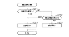
図4において、ステップS101では、自車両の進路変更がこれから行われる状況であるか否かを判定する。ここでは、2つの変更判定条件の少なくともいずれかが成立している場合に、自車両の進路変更が行われる状況であるものと判定する。 In FIG. 4, in step S <b> 101, it is determined whether or not the course of the own vehicle is to be changed. Here, when at least one of the two change determination conditions is satisfied, it is determined that the vehicle is changing the course.
図5は、進路変更判定処理の処理手順を示すサブルーチンである。図5において、ステップS201では、変更判定条件の第1判定条件、すなわち方向指示器17の操作レバーがドライバによって左指示位置又は右指示位置に操作された旨の操作信号を入力したか否かを判定する。第1判定条件が不成立の場合には、ステップS202で、変更判定条件の第2判定条件、すなわち画像データに基づき自車両が白線を跨いだことが検出されたか否かを判定する。 FIG. 5 is a subroutine showing a processing procedure of the course change determination process. In FIG. 5, in step S <b> 201, whether or not an operation signal indicating that the operation lever of the direction indicator 17 has been operated to the left instruction position or the right instruction position by the driver is input as the first determination condition of the change determination condition. judge. If the first determination condition is not satisfied, it is determined in step S202 whether or not it has been detected that the host vehicle straddles the white line based on the second determination condition of the change determination condition, that is, the image data.
ステップS201及びS202の全てで否定判定された場合には、ステップS203へ進み、自車両の進路変更は無いものと判定する。一方、ステップS201及びS202の少なくともいずれかで肯定判定されると、ステップS204へ進み、自車両の進路変更有りと判定する。 If a negative determination is made in all of steps S201 and S202, the process proceeds to step S203, and it is determined that there is no change in the course of the host vehicle. On the other hand, if an affirmative determination is made in at least one of steps S201 and S202, the process proceeds to step S204, where it is determined that there is a course change of the host vehicle.
図4の説明に戻り、ステップS101で肯定判定されると、ステップS102へ進み、予測進路RCとして第1予測進路RAを有効としているか否かを判定する。ドライバが進路変更の意思を示した直後(例えば、方向指示器17の操作レバーを操作した直後)であれば、ステップS102で肯定判定されてステップS103へ進む。ステップS103では、有効とする予測進路RCを第1予測進路RAから第2予測進路RBに切り替える。 Returning to the description of FIG. 4, when an affirmative determination is made in step S <b> 101, the process proceeds to step S <b> 102 to determine whether or not the first predicted route RA is valid as the predicted route RC. If it is immediately after the driver indicates the intention to change the course (for example, immediately after operating the operation lever of the direction indicator 17), an affirmative determination is made in step S102 and the process proceeds to step S103. In step S103, the effective predicted route RC is switched from the first predicted route RA to the second predicted route RB.
ステップS102で否定判定された場合、及びステップS103の後ではステップS104へ進む。ステップS104では、進路変更が完了したか否かを判定し、進路変更が完了していなければそのまま一旦本ルーチンを終了する。そして、ステップS104で肯定判定されるとステップS105へ進み、有効とする予測進路RCを第2予測進路RBから第1予測進路RAに切り替える。 If a negative determination is made in step S102 and after step S103, the process proceeds to step S104. In step S104, it is determined whether or not the course change has been completed. If the course change has not been completed, this routine is once terminated. Then, if an affirmative determination is made in step S104, the process proceeds to step S105, and the effective predicted route RC is switched from the second predicted route RB to the first predicted route RA.
以上詳述した本実施形態によれば、次の優れた効果が得られる。 According to the embodiment described in detail above, the following excellent effects can be obtained.
自車両の将来の走行進路の予測方法が異なる複数の進路予測手段として第1予測進路演算部21及び第2予測進路演算部22を備え、自車両の進路変更が行われるか否かに応じて、複数の進路予測手段のいずれを有効にするかを切り替える構成とした。自車両が進路変更する場合と、運転者に進路変更の意思がなく同一車線上を継続して走行している場合とでは、自車両の進行方向に対する自車両の向きなどの要素が異なり、自車両の進路を予測するための最適な手段が異なる。その点、上記構成によれば、進路変更が行われるか否かを考慮しながら、複数の進路予測手段の中から最適なものを選択することができる。これにより、自車両の進路変更時において、自車両の進路予測をより正確に実施することができる。
According to whether or not a course change of the host vehicle is performed, the first and second predicted
具体的には、複数の進路予測手段として、先行車両の移動軌跡に基づいて自車両の進路を予測する第1予測進路演算部21と、自車両のヨーレートに基づいて自車両の進路を予測する第2予測進路演算部22とを備え、第1予測進路演算部21で算出した予測進路を有効としているときに自車両の進路変更が行われると判定された場合には、有効とする予測進路RCを、第1予測進路演算部21で算出した予測進路から、第2予測進路演算部22で算出した予測進路に切り替える構成とした。進路変更時のように、自車両が道路に沿わない動きをしようとする状況では、先行車両の移動軌跡に基づく第1予測進路RAを用いて車両の走行制御を実施すると、先行車両の選択解除に遅れが発生することがある。また、先行車両の選択解除の遅れに起因して、自車両が先行車両を追い越そうとしている状況で加速遅れが生じることがある。これに対し、上記構成のようにすることで、進路変更の開始直後において、先行車両M2の存在とは無関係に、自車両のヨーレートに応じた進路予測が可能となり、その結果、進路変更時により正確な進路予測を実施することができる。
Specifically, as a plurality of route prediction means, a first predicted
自車両の進路変更が行われるものと判定された後において進路変更が完了したことを判定する手段として進路変更完了判定部33を備え、進路変更完了判定部33により進路変更が完了したと判定された場合には、有効とする予測進路RCを第2予測進路RBから第1予測進路RAに切り替える構成とした。進路変更後においてカーブに進入するタイミングで第2予測進路RBを有効としたままであると、自車両と同一車線上の先行車両ではなく、隣接車線に存在する先行車両を追従車両として誤選択するおそれがある。これに鑑み、進路変更が完了したと判定された場合には、有効とする予測進路RCを第1予測進路RAに速やかに切り替える構成とすることで、進路変更後においてカーブが到来した場合にも自車両の走行進路をより正確に予測できる。
A route change
進路変更判定部31では、自車両に備えられている方向指示器17のドライバによる操作があったことを検出した場合に、自車両の進路変更が行われるものと判定する構成とした。進路変更をしようとするドライバは、通常、実際に進路変更するためのハンドル操作の前に方向指示器17を事前にオン操作するため、ドライバの進路変更の意思がより速やかに反映されやすい。したがって、方向指示器17のオン操作に基づき自車両の進路変更が行われるか否かを判定する構成によれば、進路変更が行われる前の準備態勢の時点で、有効とする予測進路RCを第1予測進路RAから第2予測進路RBに速やかに切り替えておくことができる。その結果、例えば自車両が先行車両を追い越そうとしている状況において、先行車両の選択解除の遅れに起因する応答性の低下を好適に抑制することができる。
The course
また、進路変更を行う前に予測進路RCを第1予測進路RAから第2予測進路RBに切り替えた場合でも、直線道路の走行中では第1予測進路RAと第2予測進路RBで予測精度に殆ど差はない(図2(a)参照)。したがって、上記構成によれば、自車両の進路予測の正確性を確保しつつ、応答性の低下を抑制することができる。 In addition, even when the predicted route RC is switched from the first predicted route RA to the second predicted route RB before the route is changed, the first predicted route RA and the second predicted route RB can be predicted accurately while traveling on a straight road. There is almost no difference (see FIG. 2A). Therefore, according to the said structure, the fall of a response can be suppressed, ensuring the accuracy of the course prediction of the own vehicle.
また、進路変更判定部31では、撮像装置11からの画像データに基づき認識した白線を自車両が跨いだことが検出された場合に、自車両の進路変更が行われるものと判定する構成とした。上記構成によれば、撮像装置11で実際に検知した情報から進路変更が実際に開始されたことを判断するため、自車両が進路変更するか否かを正確に判断することができる。また、撮像装置11では一般に近距離の検知性が高く、精度の点でも好ましい。
The course
(他の実施形態)
本発明は上記実施形態に限定されず、例えば次のように実施してもよい。
(Other embodiments)
The present invention is not limited to the above embodiment, and may be implemented as follows, for example.
・上記実施形態における第1予測進路演算部21では、静止物情報と白線情報と他車移動軌跡情報とを入力し、これらの入力情報を用いて第1予測進路RAを算出する構成とした。第1予測進路RAを算出する方法はこれに限定せず、例えば他車移動軌跡情報のみを用いて第1予測進路RAを算出してもよいし、他車移動軌跡情報と静止物情報とから第1予測進路RAを算出してもよいし、あるいは他車移動軌跡情報と白線情報とから第1予測進路RAを算出してもよい。
In the first embodiment, the first predicted
・自車両が所定車速以上の車速で先行車両に追従している状況下で車両の進路変更が行われると判定された場合に、複数の進路予測手段のいずれで予測した進路を用いて車両の走行制御を実施するかを切り替える構成としてもよい。車速が十分に高い状況であればドライバが引き続き走行意思を有していることが確からしく、よってこのような場合に上記制御を実施することが望ましい。 -When it is determined that the course of the vehicle is to be changed in a situation where the host vehicle is following the preceding vehicle at a vehicle speed that is equal to or higher than the predetermined vehicle speed, the vehicle predicted by any of the plurality of course prediction means is used. It is good also as a structure which switches whether to implement driving | running | working control. If the vehicle speed is sufficiently high, it is certain that the driver will continue to drive, and therefore it is desirable to implement the above control in such a case.
・上記実施形態では、方向指示器17がドライバによってオン操作されたこと、及び撮像装置11からの画像データにより自車両が白線を跨いだことが認識されたこと、により自車両の進路変更が行われることを判定したが、進路変更の有無を判定する方法はこれらに限定されない。例えば、車両の操舵角に基づいて進路変更の有無を判定する構成としてもよい。具体的には、例えば操舵角センサ15で検出した操舵角が所定よりも大きければ、進路変更に必要な操舵が有ったものと判定する。また、撮像装置11からの画像データにより自車両が白線を跨いだことを判定する構成において、車両の操舵角の変化についても加味して判定してもよい。具体的には、撮像装置11からの画像データにより自車両が白線を跨いだことが認識され、かつ車両の操舵角が大きくなる側に変化した場合に、自車両の進路変更が行われるものと判定する。
In the above embodiment, the course of the host vehicle is changed due to the turning on of the direction indicator 17 by the driver and the recognition of the host vehicle straddling the white line by the image data from the
・上記実施形態では、進路変更判定部31からの判定信号を入力した時点からの経過時間により進路変更が完了したことを判定する構成としたが、進路変更が完了したことの判定方法はこれに限定されない。例えば、撮像装置11からの画像データを用いて進路変更が完了したことを判定してもよいし、車両の操舵角の変化に基づいて進路変更が完了したことを判定する構成としてもよい。あるいは、方向指示器17がオフされたこと(操作レバーが中立位置に操作されたこと)により進路変更が完了したことを判定する構成としてもよい。
In the above embodiment, it is configured to determine that the course change has been completed based on the elapsed time from the time when the determination signal from the course
・ドライバによって方向指示器17がオン操作された場合でも、実際には進路変更が実施されない場合がある。この点を考慮して、ドライバによって方向指示器17がオン操作されてから所定時間T1が経過した時点で、有効とする予測進路RCを第2予測進路RBから第1予測進路RAに切り替える構成としてもよい。こうした構成とすることにより、例えばカーブ路において隣接車線に存在する先行車両を追従車両として誤選択することを極力回避することができる。 Even when the direction indicator 17 is turned on by the driver, the course may not be changed in practice. Considering this point, as a configuration in which the valid predicted route RC is switched from the second predicted route RB to the first predicted route RA when a predetermined time T1 has elapsed since the turn indicator 17 was turned on by the driver. Also good. By adopting such a configuration, for example, erroneously selecting a preceding vehicle existing in an adjacent lane on a curved road as a following vehicle can be avoided as much as possible.
・上記実施形態では、物体検出手段として撮像装置及びレーダ装置を備える構成としたがこれらに限定されず、例えば送信波に超音波を用いて物体を検出するソナーを備える構成に適用してもよい。また、撮像装置を搭載しない車両に本発明を適用してもよい。 In the above embodiment, the imaging device and the radar device are provided as the object detection unit, but the invention is not limited thereto. For example, the invention may be applied to a configuration including a sonar that detects an object using an ultrasonic wave as a transmission wave. . Further, the present invention may be applied to a vehicle that is not equipped with an imaging device.
・上記実施形態では、自車両と同一の車線上を走行する先行車両に追従して走行する追従制御に適用する場合について説明したが、自車両と他車両との衝突を回避するための自車両の進路予測に本発明を適用してもよい。 In the above embodiment, the case where the present invention is applied to the follow-up control in which the vehicle follows the preceding vehicle traveling on the same lane as the host vehicle has been described, but the host vehicle for avoiding a collision between the host vehicle and another vehicle. The present invention may be applied to the course prediction.
10…走行制御装置、11…撮像装置、12…レーダ装置、13…ヨーレートセンサ、17…方向指示器、20…進路予測部、21…第1予測進路演算部、22…第2予測進路演算部、23…静止物情報取得部、24…白線情報取得部、25…他車移動軌跡取得部、26…カーブ半径推定部、30…予測進路設定部、31…進路変更判定部、32…予測切替部、33…進路変更完了判定部、35…追従車両設定部、36…制御目標値演算部、41…エンジンECU、42…ブレーキECU。
DESCRIPTION OF
Claims (4)
前記予測進路を算出する複数の進路予測手段(21,22)と、
前記自車両の進路変更が行われるか否かを判定する変更判定手段(31)と、
前記変更判定手段による判定結果に基づいて、前記複数の進路予測手段のいずれで算出した予測進路を有効とするかを切り替える予測切替手段(32)と、
を備え、
前記複数の進路予測手段は、
前記自車両の前方を走行する先行車両(M2)の移動軌跡に基づいて前記予測進路を算出する第1予測手段(21)と、
前記自車両のヨーレートに基づいて前記予測進路を算出する第2予測手段(22)と、を備え、
前記予測切替手段は、前記第1予測手段により算出した予測進路を有効としているときに前記変更判定手段により進路変更が行われると判定された場合に、前記予測進路を、前記第1予測手段により算出した予測進路から前記第2予測手段により算出した予測進路に切り替えることを特徴とする車両の走行制御装置。 A travel control device (10) for a vehicle that controls travel of the host vehicle based on a predicted course that is a future course of travel of the host vehicle (M1),
A plurality of course prediction means (21, 22) for calculating the predicted course;
Change determination means (31) for determining whether or not the course of the host vehicle is changed;
A prediction switching means (32) for switching which of the plurality of course prediction means is to be effective based on a determination result by the change determination means;
Equipped with a,
The plurality of course prediction means include
First prediction means (21) for calculating the predicted course based on a movement locus of a preceding vehicle (M2) traveling in front of the host vehicle;
Second prediction means (22) for calculating the predicted course based on the yaw rate of the host vehicle,
The prediction switching means determines the predicted course by the first prediction means when the change judgment means determines that the course is changed when the predicted course calculated by the first prediction means is valid. A travel control apparatus for a vehicle, wherein the calculated predicted route is switched to the predicted route calculated by the second prediction means .
前記予測切替手段は、前記完了判定手段により進路変更が完了したと判定された場合に、前記予測進路を、前記第2予測手段により算出した予測進路から前記第1予測手段により算出した予測進路に切り替える請求項1に記載の車両の走行制御装置。 Completion determination means (33) for determining that the course change of the host vehicle has been completed after the change determination means determines that the course change is performed,
The prediction switching means changes the predicted course from the predicted course calculated by the second predictor to the predicted course calculated by the first predictor when the completion determining means determines that the course change has been completed. The vehicle travel control apparatus according to claim 1 to be switched.
前記撮像装置により撮影された画像に基づいて前記走行道路の区画線を認識する区画線認識手段(24)を備え、
前記変更判定手段は、前記区画線認識手段により認識した区画線を前記自車両が跨いだことが検出された場合に前記自車両の進路変更が行われるものと判定する請求項1〜3のいずれか一項に記載の車両の走行制御装置。 The host vehicle is provided with an imaging device (11) for photographing a surrounding environment including a traveling road,
Comprising lane marking recognition means (24) for recognizing the lane marking of the traveling road based on an image photographed by the imaging device;
The change determination means, either a division line recognized by the division line recognition means the own vehicle is the course change of the vehicle when the thing is detected that straddle the ones with determining claims 1-3 to be performed The vehicle travel control device according to claim 1.
Priority Applications (5)
| Application Number | Priority Date | Filing Date | Title |
|---|---|---|---|
| JP2014242230A JP6430799B2 (en) | 2014-11-28 | 2014-11-28 | Vehicle travel control device |
| DE112015005364.6T DE112015005364T5 (en) | 2014-11-28 | 2015-10-05 | VEHICLE VELOCITY CONTROL DEVICE, VEHICLE SPEED CONTROL METHOD AND VEHICLE SPEED CONTROL PROGRAM |
| CN201580064590.7A CN107004367B (en) | 2014-11-28 | 2015-10-05 | Vehicle travel control device and travel control method |
| US15/529,911 US10611240B2 (en) | 2014-11-28 | 2015-10-05 | Vehicle cruise control apparatus and cruise control method |
| PCT/JP2015/078135 WO2016084478A1 (en) | 2014-11-28 | 2015-10-05 | Drive control device for vehicle, drive control method, and drive control program |
Applications Claiming Priority (1)
| Application Number | Priority Date | Filing Date | Title |
|---|---|---|---|
| JP2014242230A JP6430799B2 (en) | 2014-11-28 | 2014-11-28 | Vehicle travel control device |
Publications (3)
| Publication Number | Publication Date |
|---|---|
| JP2016103220A JP2016103220A (en) | 2016-06-02 |
| JP2016103220A5 JP2016103220A5 (en) | 2017-02-09 |
| JP6430799B2 true JP6430799B2 (en) | 2018-11-28 |
Family
ID=56074056
Family Applications (1)
| Application Number | Title | Priority Date | Filing Date |
|---|---|---|---|
| JP2014242230A Active JP6430799B2 (en) | 2014-11-28 | 2014-11-28 | Vehicle travel control device |
Country Status (5)
| Country | Link |
|---|---|
| US (1) | US10611240B2 (en) |
| JP (1) | JP6430799B2 (en) |
| CN (1) | CN107004367B (en) |
| DE (1) | DE112015005364T5 (en) |
| WO (1) | WO2016084478A1 (en) |
Families Citing this family (9)
| Publication number | Priority date | Publication date | Assignee | Title |
|---|---|---|---|---|
| JP6293213B2 (en) * | 2016-08-01 | 2018-03-14 | 三菱電機株式会社 | Lane marking detection correction device, lane marking detection correction method, and automatic driving system |
| US10629079B2 (en) * | 2016-12-05 | 2020-04-21 | Ford Global Technologies, Llc | Vehicle collision avoidance |
| JP6795792B2 (en) * | 2017-09-28 | 2020-12-02 | トヨタ自動車株式会社 | Driving support device |
| US20200339156A1 (en) * | 2017-12-27 | 2020-10-29 | Honda Motor Co., Ltd. | Vehicle control device, vehicle control method, and storage medium |
| JP7156924B2 (en) * | 2018-11-29 | 2022-10-19 | 株式会社Soken | Lane boundary setting device, lane boundary setting method |
| EP3654698B1 (en) * | 2018-11-16 | 2022-01-19 | Volkswagen Aktiengesellschaft | A method for performing a handover process for a mobile radio network terminal in a mobile radio network, corresponding apparatuses for performing steps in the method, vehicle and core network management device and corresponding computer programs |
| FR3096948B1 (en) * | 2019-06-06 | 2021-05-14 | Renault Sas | Method for calculating the lateral position of a motor vehicle |
| JP7235015B2 (en) | 2020-07-17 | 2023-03-08 | トヨタ自動車株式会社 | automatic steering system |
| CN114141009B (en) * | 2021-10-31 | 2023-01-31 | 际络科技(上海)有限公司 | Simulation traffic flow lane changing method and system based on multi-time sequence network |
Family Cites Families (27)
| Publication number | Priority date | Publication date | Assignee | Title |
|---|---|---|---|---|
| DE19637245C2 (en) * | 1996-09-13 | 2000-02-24 | Bosch Gmbh Robert | Method and device for regulating the speed of a vehicle |
| DE19722947C1 (en) * | 1997-05-31 | 1999-02-25 | Bosch Gmbh Robert | Method and device for determining a future course range of a vehicle |
| DE19855400A1 (en) | 1998-12-01 | 2000-06-15 | Bosch Gmbh Robert | Method and device for determining a future course range of a vehicle |
| JP2001134320A (en) * | 1999-11-01 | 2001-05-18 | Honda Motor Co Ltd | Lane follow-up controller |
| JP4059033B2 (en) * | 2002-08-12 | 2008-03-12 | 日産自動車株式会社 | Travel route generator |
| JP2004161095A (en) * | 2002-11-12 | 2004-06-10 | Nissan Motor Co Ltd | Alarming device for vehicle |
| JP4379199B2 (en) * | 2004-05-17 | 2009-12-09 | 日産自動車株式会社 | Lane change support apparatus and method |
| DE102004028404A1 (en) * | 2004-06-14 | 2006-01-19 | Daimlerchrysler Ag | Method for estimating the course of a lane of a motor vehicle |
| JP4600057B2 (en) * | 2005-01-31 | 2010-12-15 | 株式会社ジェイテクト | Vehicle steering system |
| JP4525670B2 (en) * | 2006-11-20 | 2010-08-18 | トヨタ自動車株式会社 | Travel control plan generation system |
| CN100492437C (en) * | 2007-06-01 | 2009-05-27 | 清华大学 | Quick identification method for object vehicle lane changing |
| JP4207088B2 (en) * | 2007-06-20 | 2009-01-14 | トヨタ自動車株式会社 | Vehicle travel estimation device |
| CN102348592B (en) * | 2009-04-21 | 2014-08-06 | 丰田自动车株式会社 | Driving assistance apparatus |
| JP4973687B2 (en) * | 2009-05-13 | 2012-07-11 | トヨタ自動車株式会社 | Driving support device |
| JP2011098586A (en) * | 2009-11-04 | 2011-05-19 | Mitsubishi Electric Corp | Preceding vehicle selection device and preceding vehicle selection method |
| US8670903B2 (en) * | 2011-05-05 | 2014-03-11 | GM Global Technology Operations LLC | Lane centering fail-safe control using differential braking |
| JP5879753B2 (en) * | 2011-06-02 | 2016-03-08 | トヨタ自動車株式会社 | Vehicle control device |
| KR101833874B1 (en) * | 2011-07-14 | 2018-03-05 | 현대모비스 주식회사 | Smart Cruise Control System Applying Variable Curvature And Method Thereof |
| CN202174990U (en) * | 2011-07-29 | 2012-03-28 | 富士重工业株式会社 | Vehicle running control device |
| JP2013067302A (en) * | 2011-09-24 | 2013-04-18 | Denso Corp | Apparatus and system for controlling follow travel |
| US9187117B2 (en) * | 2012-01-17 | 2015-11-17 | Ford Global Technologies, Llc | Autonomous lane control system |
| DE102012013376A1 (en) * | 2012-07-05 | 2014-01-09 | GM Global Technology Operations, LLC (n.d. Ges. d. Staates Delaware) | Driver assistance system |
| CN102800213B (en) * | 2012-08-27 | 2014-06-18 | 武汉大学 | Traffic-priority-based lane change danger collision avoiding method |
| JP5406395B1 (en) * | 2013-03-28 | 2014-02-05 | 富士重工業株式会社 | Vehicle control device |
| US9045144B2 (en) * | 2013-05-09 | 2015-06-02 | Robert Bosch Gmbh | Third-order polynomial-based course prediction for driver assistance functions |
| CN103481842B (en) * | 2013-09-09 | 2015-12-02 | 华南理工大学 | A kind of changing method of moving vehicles detection and tracking pattern |
| CN103754221B (en) * | 2014-01-24 | 2017-05-24 | 清华大学 | Vehicle adaptive cruise control system |
-
2014
- 2014-11-28 JP JP2014242230A patent/JP6430799B2/en active Active
-
2015
- 2015-10-05 CN CN201580064590.7A patent/CN107004367B/en active Active
- 2015-10-05 DE DE112015005364.6T patent/DE112015005364T5/en active Pending
- 2015-10-05 WO PCT/JP2015/078135 patent/WO2016084478A1/en active Application Filing
- 2015-10-05 US US15/529,911 patent/US10611240B2/en active Active
Also Published As
| Publication number | Publication date |
|---|---|
| US10611240B2 (en) | 2020-04-07 |
| CN107004367A (en) | 2017-08-01 |
| DE112015005364T5 (en) | 2017-08-10 |
| WO2016084478A1 (en) | 2016-06-02 |
| JP2016103220A (en) | 2016-06-02 |
| US20170326980A1 (en) | 2017-11-16 |
| CN107004367B (en) | 2020-08-07 |
Similar Documents
| Publication | Publication Date | Title |
|---|---|---|
| JP6430799B2 (en) | Vehicle travel control device | |
| JP6356586B2 (en) | Vehicle travel control device | |
| US10780884B2 (en) | Vehicle cruise control apparatus and vehicle cruise control method | |
| JP6363517B2 (en) | Vehicle travel control device | |
| JP6404722B2 (en) | Vehicle travel control device | |
| JP6356585B2 (en) | Vehicle travel control device | |
| JP6363516B2 (en) | Vehicle travel control device | |
| JP6507839B2 (en) | Vehicle travel control device | |
| JP6447431B2 (en) | Vehicle control device | |
| JP6369390B2 (en) | Lane junction determination device | |
| CN107209998B (en) | Lane line recognition device and lane line recognition method | |
| JP6363519B2 (en) | Vehicle control device | |
| US20170066445A1 (en) | Vehicle control apparatus | |
| JP6443292B2 (en) | Driving support device and driving support method | |
| JP6330868B2 (en) | Vehicle control device | |
| JP6477377B2 (en) | Vehicle control apparatus and vehicle control method |
Legal Events
| Date | Code | Title | Description |
|---|---|---|---|
| A521 | Request for written amendment filed |
Free format text: JAPANESE INTERMEDIATE CODE: A523 Effective date: 20161222 |
|
| A621 | Written request for application examination |
Free format text: JAPANESE INTERMEDIATE CODE: A621 Effective date: 20170608 |
|
| A131 | Notification of reasons for refusal |
Free format text: JAPANESE INTERMEDIATE CODE: A131 Effective date: 20180306 |
|
| TRDD | Decision of grant or rejection written | ||
| A01 | Written decision to grant a patent or to grant a registration (utility model) |
Free format text: JAPANESE INTERMEDIATE CODE: A01 Effective date: 20181009 |
|
| A61 | First payment of annual fees (during grant procedure) |
Free format text: JAPANESE INTERMEDIATE CODE: A61 Effective date: 20181101 |
|
| R150 | Certificate of patent or registration of utility model |
Ref document number: 6430799 Country of ref document: JP Free format text: JAPANESE INTERMEDIATE CODE: R150 |
|
| R250 | Receipt of annual fees |
Free format text: JAPANESE INTERMEDIATE CODE: R250 |
|
| R250 | Receipt of annual fees |
Free format text: JAPANESE INTERMEDIATE CODE: R250 |
|
| R250 | Receipt of annual fees |
Free format text: JAPANESE INTERMEDIATE CODE: R250 |