JP6430425B2 - Motor drive control device, motor drive control method, and tube pump - Google Patents
Motor drive control device, motor drive control method, and tube pump Download PDFInfo
- Publication number
- JP6430425B2 JP6430425B2 JP2016047013A JP2016047013A JP6430425B2 JP 6430425 B2 JP6430425 B2 JP 6430425B2 JP 2016047013 A JP2016047013 A JP 2016047013A JP 2016047013 A JP2016047013 A JP 2016047013A JP 6430425 B2 JP6430425 B2 JP 6430425B2
- Authority
- JP
- Japan
- Prior art keywords
- motor
- signal
- drive control
- period
- speed command
- Prior art date
- Legal status (The legal status is an assumption and is not a legal conclusion. Google has not performed a legal analysis and makes no representation as to the accuracy of the status listed.)
- Active
Links
Images


Classifications
-
- H—ELECTRICITY
- H02—GENERATION; CONVERSION OR DISTRIBUTION OF ELECTRIC POWER
- H02P—CONTROL OR REGULATION OF ELECTRIC MOTORS, ELECTRIC GENERATORS OR DYNAMO-ELECTRIC CONVERTERS; CONTROLLING TRANSFORMERS, REACTORS OR CHOKE COILS
- H02P6/00—Arrangements for controlling synchronous motors or other dynamo-electric motors using electronic commutation dependent on the rotor position; Electronic commutators therefor
- H02P6/08—Arrangements for controlling the speed or torque of a single motor
-
- H—ELECTRICITY
- H02—GENERATION; CONVERSION OR DISTRIBUTION OF ELECTRIC POWER
- H02P—CONTROL OR REGULATION OF ELECTRIC MOTORS, ELECTRIC GENERATORS OR DYNAMO-ELECTRIC CONVERTERS; CONTROLLING TRANSFORMERS, REACTORS OR CHOKE COILS
- H02P6/00—Arrangements for controlling synchronous motors or other dynamo-electric motors using electronic commutation dependent on the rotor position; Electronic commutators therefor
- H02P6/14—Electronic commutators
- H02P6/16—Circuit arrangements for detecting position
- H02P6/17—Circuit arrangements for detecting position and for generating speed information
-
- A—HUMAN NECESSITIES
- A61—MEDICAL OR VETERINARY SCIENCE; HYGIENE
- A61M—DEVICES FOR INTRODUCING MEDIA INTO, OR ONTO, THE BODY; DEVICES FOR TRANSDUCING BODY MEDIA OR FOR TAKING MEDIA FROM THE BODY; DEVICES FOR PRODUCING OR ENDING SLEEP OR STUPOR
- A61M60/00—Blood pumps; Devices for mechanical circulatory actuation; Balloon pumps for circulatory assistance
- A61M60/10—Location thereof with respect to the patient's body
- A61M60/104—Extracorporeal pumps, i.e. the blood being pumped outside the patient's body
- A61M60/109—Extracorporeal pumps, i.e. the blood being pumped outside the patient's body incorporated within extracorporeal blood circuits or systems
- A61M60/113—Extracorporeal pumps, i.e. the blood being pumped outside the patient's body incorporated within extracorporeal blood circuits or systems in other functional devices, e.g. dialysers or heart-lung machines
-
- A—HUMAN NECESSITIES
- A61—MEDICAL OR VETERINARY SCIENCE; HYGIENE
- A61M—DEVICES FOR INTRODUCING MEDIA INTO, OR ONTO, THE BODY; DEVICES FOR TRANSDUCING BODY MEDIA OR FOR TAKING MEDIA FROM THE BODY; DEVICES FOR PRODUCING OR ENDING SLEEP OR STUPOR
- A61M60/00—Blood pumps; Devices for mechanical circulatory actuation; Balloon pumps for circulatory assistance
- A61M60/20—Type thereof
- A61M60/205—Non-positive displacement blood pumps
- A61M60/216—Non-positive displacement blood pumps including a rotating member acting on the blood, e.g. impeller
-
- A—HUMAN NECESSITIES
- A61—MEDICAL OR VETERINARY SCIENCE; HYGIENE
- A61M—DEVICES FOR INTRODUCING MEDIA INTO, OR ONTO, THE BODY; DEVICES FOR TRANSDUCING BODY MEDIA OR FOR TAKING MEDIA FROM THE BODY; DEVICES FOR PRODUCING OR ENDING SLEEP OR STUPOR
- A61M60/00—Blood pumps; Devices for mechanical circulatory actuation; Balloon pumps for circulatory assistance
- A61M60/20—Type thereof
- A61M60/247—Positive displacement blood pumps
- A61M60/253—Positive displacement blood pumps including a displacement member directly acting on the blood
- A61M60/268—Positive displacement blood pumps including a displacement member directly acting on the blood the displacement member being flexible, e.g. membranes, diaphragms or bladders
- A61M60/279—Peristaltic pumps, e.g. roller pumps
-
- A—HUMAN NECESSITIES
- A61—MEDICAL OR VETERINARY SCIENCE; HYGIENE
- A61M—DEVICES FOR INTRODUCING MEDIA INTO, OR ONTO, THE BODY; DEVICES FOR TRANSDUCING BODY MEDIA OR FOR TAKING MEDIA FROM THE BODY; DEVICES FOR PRODUCING OR ENDING SLEEP OR STUPOR
- A61M60/00—Blood pumps; Devices for mechanical circulatory actuation; Balloon pumps for circulatory assistance
- A61M60/40—Details relating to driving
- A61M60/403—Details relating to driving for non-positive displacement blood pumps
- A61M60/422—Details relating to driving for non-positive displacement blood pumps the force acting on the blood contacting member being electromagnetic, e.g. using canned motor pumps
-
- A—HUMAN NECESSITIES
- A61—MEDICAL OR VETERINARY SCIENCE; HYGIENE
- A61M—DEVICES FOR INTRODUCING MEDIA INTO, OR ONTO, THE BODY; DEVICES FOR TRANSDUCING BODY MEDIA OR FOR TAKING MEDIA FROM THE BODY; DEVICES FOR PRODUCING OR ENDING SLEEP OR STUPOR
- A61M60/00—Blood pumps; Devices for mechanical circulatory actuation; Balloon pumps for circulatory assistance
- A61M60/50—Details relating to control
- A61M60/508—Electronic control means, e.g. for feedback regulation
- A61M60/515—Regulation using real-time patient data
-
- A—HUMAN NECESSITIES
- A61—MEDICAL OR VETERINARY SCIENCE; HYGIENE
- A61M—DEVICES FOR INTRODUCING MEDIA INTO, OR ONTO, THE BODY; DEVICES FOR TRANSDUCING BODY MEDIA OR FOR TAKING MEDIA FROM THE BODY; DEVICES FOR PRODUCING OR ENDING SLEEP OR STUPOR
- A61M60/00—Blood pumps; Devices for mechanical circulatory actuation; Balloon pumps for circulatory assistance
- A61M60/50—Details relating to control
- A61M60/508—Electronic control means, e.g. for feedback regulation
- A61M60/538—Regulation using real-time blood pump operational parameter data, e.g. motor current
-
- F—MECHANICAL ENGINEERING; LIGHTING; HEATING; WEAPONS; BLASTING
- F04—POSITIVE - DISPLACEMENT MACHINES FOR LIQUIDS; PUMPS FOR LIQUIDS OR ELASTIC FLUIDS
- F04B—POSITIVE-DISPLACEMENT MACHINES FOR LIQUIDS; PUMPS
- F04B43/00—Machines, pumps, or pumping installations having flexible working members
- F04B43/12—Machines, pumps, or pumping installations having flexible working members having peristaltic action
- F04B43/1253—Machines, pumps, or pumping installations having flexible working members having peristaltic action by using two or more rollers as squeezing elements, the rollers moving on an arc of a circle during squeezing
-
- F—MECHANICAL ENGINEERING; LIGHTING; HEATING; WEAPONS; BLASTING
- F04—POSITIVE - DISPLACEMENT MACHINES FOR LIQUIDS; PUMPS FOR LIQUIDS OR ELASTIC FLUIDS
- F04B—POSITIVE-DISPLACEMENT MACHINES FOR LIQUIDS; PUMPS
- F04B49/00—Control, e.g. of pump delivery, or pump pressure of, or safety measures for, machines, pumps, or pumping installations, not otherwise provided for, or of interest apart from, groups F04B1/00 - F04B47/00
- F04B49/20—Control, e.g. of pump delivery, or pump pressure of, or safety measures for, machines, pumps, or pumping installations, not otherwise provided for, or of interest apart from, groups F04B1/00 - F04B47/00 by changing the driving speed
-
- H—ELECTRICITY
- H02—GENERATION; CONVERSION OR DISTRIBUTION OF ELECTRIC POWER
- H02P—CONTROL OR REGULATION OF ELECTRIC MOTORS, ELECTRIC GENERATORS OR DYNAMO-ELECTRIC CONVERTERS; CONTROLLING TRANSFORMERS, REACTORS OR CHOKE COILS
- H02P23/00—Arrangements or methods for the control of AC motors characterised by a control method other than vector control
- H02P23/03—Arrangements or methods for the control of AC motors characterised by a control method other than vector control specially adapted for very low speeds
-
- H—ELECTRICITY
- H02—GENERATION; CONVERSION OR DISTRIBUTION OF ELECTRIC POWER
- H02P—CONTROL OR REGULATION OF ELECTRIC MOTORS, ELECTRIC GENERATORS OR DYNAMO-ELECTRIC CONVERTERS; CONTROLLING TRANSFORMERS, REACTORS OR CHOKE COILS
- H02P27/00—Arrangements or methods for the control of AC motors characterised by the kind of supply voltage
- H02P27/04—Arrangements or methods for the control of AC motors characterised by the kind of supply voltage using variable-frequency supply voltage, e.g. inverter or converter supply voltage
- H02P27/06—Arrangements or methods for the control of AC motors characterised by the kind of supply voltage using variable-frequency supply voltage, e.g. inverter or converter supply voltage using dc to ac converters or inverters
- H02P27/08—Arrangements or methods for the control of AC motors characterised by the kind of supply voltage using variable-frequency supply voltage, e.g. inverter or converter supply voltage using dc to ac converters or inverters with pulse width modulation
-
- H—ELECTRICITY
- H02—GENERATION; CONVERSION OR DISTRIBUTION OF ELECTRIC POWER
- H02P—CONTROL OR REGULATION OF ELECTRIC MOTORS, ELECTRIC GENERATORS OR DYNAMO-ELECTRIC CONVERTERS; CONTROLLING TRANSFORMERS, REACTORS OR CHOKE COILS
- H02P6/00—Arrangements for controlling synchronous motors or other dynamo-electric motors using electronic commutation dependent on the rotor position; Electronic commutators therefor
- H02P6/06—Arrangements for speed regulation of a single motor wherein the motor speed is measured and compared with a given physical value so as to adjust the motor speed
-
- H—ELECTRICITY
- H02—GENERATION; CONVERSION OR DISTRIBUTION OF ELECTRIC POWER
- H02P—CONTROL OR REGULATION OF ELECTRIC MOTORS, ELECTRIC GENERATORS OR DYNAMO-ELECTRIC CONVERTERS; CONTROLLING TRANSFORMERS, REACTORS OR CHOKE COILS
- H02P2205/00—Indexing scheme relating to controlling arrangements characterised by the control loops
- H02P2205/07—Speed loop, i.e. comparison of the motor speed with a speed reference
Description
本発明は、モータ駆動装置、モータ駆動方法及びチューブポンプに関する。 The present invention relates to a motor drive device, a motor drive method, and a tube pump.
従来、ポンプ装置として、チューブポンプが知られている。チューブポンプは、モータによりローラを回転させながらチューブを押し潰すことにより、チューブ内の液体を送出する。チューブポンプは、医療機器に使用されており、例えば、ブラシレスDCモータにより、ローラを有するロータを回転させる人工透析用ポンプ装置(血液ポンプ)が知られている。 Conventionally, a tube pump is known as a pump device. A tube pump sends out the liquid in a tube by crushing a tube, rotating a roller with a motor. Tube pumps are used in medical equipment. For example, a pump device for artificial dialysis (blood pump) that rotates a rotor having a roller by a brushless DC motor is known.
例えば、人工透析用ポンプ装置では、ロータとブラシレスDCモータとの間に、減速機が設けられる。減速機は、血液ポンプのロータを低速で回転させ、また、低速回転でも高いトルクを発生させるために、必要となる。 For example, in an artificial dialysis pump device, a speed reducer is provided between a rotor and a brushless DC motor. The speed reducer is necessary for rotating the rotor of the blood pump at a low speed and generating a high torque even at a low speed.
ここで、利用者によっては、例えば、モータの仕様を下回る回転速度で、人工透析用ポンプ装置を動作させたいという要求がある。 Here, depending on the user, for example, there is a demand to operate the artificial dialysis pump device at a rotational speed lower than the specification of the motor.
本発明は、上記に鑑みてなされたものであって、仕様範囲外の低速の回転速度でモータを回転させることができるモータ駆動制御装置、モータ駆動制御方法及びチューブポンプを提供することを目的とする。 The present invention has been made in view of the above, and an object of the present invention is to provide a motor drive control device, a motor drive control method, and a tube pump that can rotate a motor at a low rotational speed outside the specification range. To do.
上述した課題を解決し、目的を達成するために、本発明の一態様に係るモータ駆動制御装置は、速度指令信号の入力により、駆動制御信号を生成する制御部と、前記駆動制御信号の入力により、駆動信号を生成しモータに出力するモータ駆動部と、を備え、前記速度指令信号は、単位時間当たりのパルス数が回転速度となるパルス信号であり、前記制御部は、前記速度指令信号の入力期間で前記駆動制御信号を生成し、前記速度指令信号の入力停止期間で前記駆動制御信号の生成を停止することを繰り返すことで、前記モータが回転する運転期間と、非励磁状態で前記モータが停止する停止期間とを繰り返させるとともに、前記運転期間と前記停止期間とを繰り返させることで、前記モータの1回転当たりの回転速度を、前記速度指令信号に対応する第1の回転速度より低速度の第2の回転速度とする。 In order to solve the above-described problems and achieve the object, a motor drive control device according to one aspect of the present invention includes a control unit that generates a drive control signal by inputting a speed command signal, and an input of the drive control signal A motor drive unit that generates a drive signal and outputs the drive signal to the motor, wherein the speed command signal is a pulse signal in which the number of pulses per unit time is a rotational speed, and the control unit The drive control signal is generated during the input period of time, and the generation of the drive control signal is stopped during the input stop period of the speed command signal, thereby repeating the operation period during which the motor rotates and the non-excited state. together to repeat a stop period in which the motor is stopped, the by causing repeated and the operation period and the stop period, the rotational speed per revolution of the motor, the speed command signal Than the first rotational speed to respond to the low speed of the second rotation speed.
本発明の一態様によれば、仕様範囲外の低速の回転速度でモータを回転させることができる。 According to one aspect of the present invention, the motor can be rotated at a low rotational speed outside the specification range.
以下、実施形態に係るモータ駆動制御装置、モータ駆動制御方法及びチューブポンプについて図面を参照して説明する。 Hereinafter, a motor drive control device, a motor drive control method, and a tube pump according to embodiments will be described with reference to the drawings.
(実施形態)
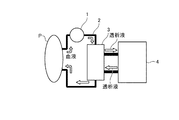
以下では、本実施形態に係るモータ駆動制御装置が用いられるチューブポンプが、人工透析システムの血液ポンプである場合について説明する。図1は、本実施形態に係る血液ポンプが組み込まれる人工透析システムの構成例を示す図である。
(Embodiment)
Below, the case where the tube pump in which the motor drive control device concerning this embodiment is used is a blood pump of an artificial dialysis system is explained. FIG. 1 is a diagram illustrating a configuration example of an artificial dialysis system in which a blood pump according to the present embodiment is incorporated.
図1に示す人工透析システムは、血液ポンプ1、ダイアライザー3及び透析液供給装置4を有する。血液ポンプ1は、チューブ2を介して、患者Pの血液をダイアライザー3に搬送する(脱血)。ダイアライザー3は、半透膜と、透析液供給装置4から供給される透析液とにより、患者Pの血液に対して、老廃物除去、電解質維持、水分量維持の処理を行う。血液ポンプ1は、チューブ2を介して、ダイアライザー3により処理された血液を患者Pに戻す(返血)。
The artificial dialysis system shown in FIG. 1 includes a
図2及び図3は、図1に示す血液ポンプ1を説明するための図である。図2に示すように、血液ポンプ1は、モータ装置10、減速機20及びポンプシステム30を有する。なお、図2は、図1に示す血液ポンプ1を側面側から見た図であり、図3は、図1に示す血液ポンプ1をポンプシステム30側から見た図である。
2 and 3 are diagrams for explaining the
図2において、モータ装置10は、減速機20を介して、ポンプシステム30のロータ32に回転駆動力を供給する駆動源であり、後述するモータ11を内蔵する。減速機20は、モータ装置10(モータ11)の回転軸と接続され、モータ11の回転速度を所定の減速比で減速する。ポンプシステム30は、減速機20の回転軸(出力軸)と接続される。
In FIG. 2, the
ポンプシステム30は、図3に示すように、ハウジング31と、ロータ32と、ローラ支持部33と、ローラ34aと、ローラ34bとを有する。ハウジング31は、内部にチューブ2及びロータ32の収納空間が形成されている。チューブ2は、ハウジング31が有する円弧状の内周壁面に沿って配設される。ロータ32は、減速機20の回転軸(出力軸)と接続される。
As shown in FIG. 3, the
ローラ支持部33は、ロータ32と接続され、ロータ32の回転とともに回転する。ローラ支持部33の両端には、ローラ34a及びローラ34bがそれぞれ取り付けられている。ローラ支持部33は、チューブ2を押圧するローラ34a及びローラ34bを回転自在に支持する。ローラ34a及びローラ34bは、ローラ支持部33の回転とともに回転する。すなわち、ローラ34a及びローラ34bは、モータ装置10(モータ11)の駆動により回転することで、ハウジング31の内周壁面に沿って配設されたチューブ2を押圧し、チューブ2内の液体(血液)を送出する。
The
図4は、図1に示すモータ装置10の構成例を示すブロック図である。モータ装置10は、図4に示すように、モータ11と、制御部12と、モータ駆動部13と、エンコーダ(位置検出器の一例)14と、ホール素子15とを有する。
FIG. 4 is a block diagram showing a configuration example of the
モータ11は、減速機20を介して、ポンプシステム30と接続される。モータ11は、例えば、3相のブラシレスDCモータである。モータ11は、制御部12及びモータ駆動部13を含むモータ駆動制御装置により駆動制御される。なお、モータ駆動制御装置として、エンコーダ14及びホール素子15が含まれても良い。
The
モータ駆動部13は、直流電源(図4のDCを参照)に接続され、制御部12が生成した駆動制御信号(後述)の入力により、駆動信号を生成しモータ11に出力する。例えば、モータ駆動部13は、アナログ集積回路であるプリドライブ回路と、インバータ回路とを有する。インバータ回路は、プリドライブ回路から出力された出力信号に基づいてモータ11に駆動信号を出力し、モータ11が備える3つの電機子コイルに通電する。インバータ回路は、例えば、直流電源の両端に設けられた2つのスイッチ素子の直列回路の対が、3つの電機子コイルの各相(U相、V相、W相)に対してそれぞれ配置されて構成されている。2つのスイッチ素子の各対において、スイッチ素子同士の接続点に、モータ11の各相の端子が接続されている。
The
プリドライブ回路は、駆動制御信号(後述)による制御に基づいて、インバータ回路を駆動するための出力信号を生成し、インバータ回路に出力する。出力信号としては、例えば、インバータ回路の各スイッチ素子に対応する6種類のスイッチング信号が出力される。これらの出力信号が出力されることで、それぞれの出力信号に対応するスイッチ素子がオン、オフ動作を行い、モータ11に駆動信号が出力されてモータ11の各相に電力が供給される。
The pre-drive circuit generates an output signal for driving the inverter circuit based on control by a drive control signal (described later), and outputs the output signal to the inverter circuit. As the output signal, for example, six types of switching signals corresponding to each switch element of the inverter circuit are output. By outputting these output signals, the switch elements corresponding to the respective output signals are turned on and off, a drive signal is output to the
ホール素子15は、モータ11(回転子)の回転位置を検出するための信号(ホール信号)を、モータ駆動部13のプリドライブ回路に出力する。プリドライブ回路は、ホール信号に基づいて、インバータ回路の各スイッチ素子のオン、オフ動作を切り替えるタイミングを調整する。なお、ホール素子15の代わりに、ホールICが用いられる場合であっても良い。
The
制御部12は、外部装置である速度指令信号生成部100と接続される。制御部12は、例えば、マイクロプロセッサ(Micro-Processing Unit:MPU)により構成される。制御部12は、速度指令信号の入力により、駆動制御信号を生成する。速度指令信号は、速度指令信号生成部100により生成される信号であり、モータ11の目標回転速度を指定する指令情報である。具体的には、速度指令信号は、パルス数が回転ステップ数となり、単位時間当たりのパルス数が回転速度となるパルス信号である。
The
速度指令信号生成部100は、例えば、パルス周波数変調(Pulse Frequency Modulation:PFM)により、目標回転速度に応じた周波数のクロック信号を速度指令信号として生成し、制御部12に出力する。制御部12は、例えば、パルス幅変調(Pulse Width Modulation:PWM)により、クロック信号に対応する回転速度でモータ11を回転させるためのPWM信号を駆動制御信号として生成する。
The speed command
エンコーダ14は、モータ11(回転子)の位置を検出する位置検出器の一例である。エンコーダ14は、速度指令信号(クロック信号)と同期したパルス信号を出力し、当該パルス信号のカウント数に基づく検出信号(エンコーダ信号)を出力する。例えば、エンコーダ14は、クロック信号に対応する回転速度でモータ11が回転している場合、クロック信号の立ち上がりエッジのタイミングで、A相からの信号と、B相からの信号とを交互に出力する。エンコーダ14は、カウンタにより、A相の出力波形の立ち上がり位置/立ち下がり位置と、B相の出力波形の立ち上がり位置/立ち下がり位置とをカウントすることで、エンコーダ信号を出力する。
The
制御部12は、速度指令信号(クロック信号)とともに、エンコーダ14が出力するエンコーダ信号とに基づいて、駆動制御信号(PWM信号)を生成し、モータ駆動部13に出力する。例えば、制御部12は、クロック信号の入力により、モータ11が回転している間、クロック信号のカウント数と、エンコーダ信号のカウント数とを比較する。カウント数が異なる場合、制御部12は、カウント数が一致するよう、デューティ比を変更したPWM信号を生成し、モータ駆動部13に出力する。なお、制御部12は、クロック信号の入力によりモータ11が回転している間、エンコーダ14が出力するエンコーダ信号の代わりに、ホール素子15が出力する信号を用いて、モータ11の回転速度を維持する制御を行っても良い。
The
ところで、図1に示す血液ポンプ1が有する減速機20は、ロータ32を低速で回転させ、また、低速回転でも高いトルクを発生させるために、血液ポンプ1に設置される。しかし、利用者によっては、例えば、モータ11の仕様を下回る回転速度で、血液ポンプ1を動作させたいという要求がある。
Meanwhile, the
そこで、本実施形態では、仕様範囲外の低速の回転速度でモータ装置10(モータ11)を回転させるため、モータ駆動制御装置としての制御部12及びモータ駆動部13は、以下に説明するモータ駆動制御方法を実行する。
Therefore, in the present embodiment, since the motor device 10 (motor 11) is rotated at a low rotational speed outside the specification range, the
制御部12は、速度指令信号の入力期間で駆動制御信号を生成し、速度指令信号の入力停止期間で駆動制御信号の生成を停止することを繰り返す。モータ駆動部13は、速度指令信号の入力期間において生成された駆動制御信号の入力により、駆動信号を生成しモータ11に出力し(出力ステップ)、速度指令信号の入力停止期間において駆動制御信号の生成が停止されることにより、駆動信号の出力を停止する(停止ステップ)ことを繰り返す(繰り返しステップ)。
The
これにより、制御部12は、モータ11が回転する運転期間と、非励磁状態でモータ11が停止する停止期間とを繰り返させる。すなわち、モータ11は、運転期間と停止期間とを繰り返す間欠動作を実行する。図5及び図6は、本実施形態で実行される間欠動作を説明するための図である。
Thereby, the
図5に示すタイミングチャートの一例では、説明の簡略化のため、運転期間のために入力されるクロック信号(CLK)の数を8個としている。速度指令信号生成部100は、例えば、ユーザの指示により、クロック信号の出力を開始する。制御部12は、クロック信号が入力するとPWM信号を生成し、モータ駆動部13に出力する。モータ駆動部13は、PWM信号に基づき、モータ11に駆動信号を出力し、モータ11を駆動する。なお、実際には、モータ11の3相それぞれに、6種類の信号がそれぞれのタイミングで駆動信号として出力されるが、図5の「駆動信号」では、6種類の信号のいずれかが出力している期間を、1つのパルス波で示している。
In the example of the timing chart shown in FIG. 5, the number of clock signals (CLK) input for the operation period is eight for the sake of simplicity of explanation. For example, the speed command
駆動信号の入力により、運転期間が開始し、モータ11の回転が開始する。エンコーダ14は、クロック信号の立ち上がりエッジのタイミングで、A相からの信号と、B相からの信号とを交互に出力する(図5の「エンコーダA相」及び「エンコーダB相」を参照)。エンコーダ14は、カウンタにより、A相の出力波形の立ち上がり位置/立ち下がり位置と、B相の出力波形の立ち上がり位置/立ち下がり位置とをカウントしたエンコーダ信号を出力する(図5の「エンコーダカウント」を参照)。なお、制御部12は、上述したように、運転期間中、クロック信号とエンコーダ信号とに基づいて、回転速度を一定に維持する通常の制御を行う。
Due to the input of the drive signal, the operation period starts and the rotation of the
そして、速度指令信号生成部100は、8個のクロック信号を出力し、クロック信号の生成を停止する(図5の「CLK」を参照)。制御部12は、クロック信号の入力停止により、PWM信号の生成を停止する。これにより、モータ駆動部13は、駆動信号の出力を停止する(図5の「駆動信号」を参照)。これにより、運転期間が終了し、停止期間となり、モータ11は、非励磁状態となって停止する。モータ11の駆動が停止すると、エンコーダ14は、クロック信号と同じカウント数のエンコーダ信号を出力し、出力を停止する。図5の「エンコーダカウント」では、エンコーダ14が、クロック信号のカウント数と同じ8個のエンコーダ信号を出力して、エンコーダ信号の出力を停止することを示している。モータ11は、再度、速度指令信号生成部100がクロック信号の出力を開始するまで、停止期間となる。
Then, the speed command
次に、間欠動作の設定について、図6等を用いて説明する。図6は、間欠動作において、クロック信号(CLK)が入力する期間Aと、クロック信号(CLK)の入力が停止する期間Bとが交互に繰り返されることを示している。期間Aは、モータ11が励磁状態となって回転する運転期間に対応し、期間Bは、モータ11が非励磁状態となって停止する停止期間に対応する。運転期間と停止期間とを交互に繰り返すことで、モータ11の1回転当たりの回転速度は、速度指令信号(クロック信号)に対応する第1の回転速度より低速度の第2の回転速度となる。
Next, setting of intermittent operation will be described with reference to FIG. FIG. 6 shows that in the intermittent operation, the period A in which the clock signal (CLK) is input and the period B in which the input of the clock signal (CLK) is stopped are alternately repeated. The period A corresponds to an operation period in which the
ここで、運転期間(期間A)の長さと、停止期間(期間B)の長さとは、第1の回転速度と第2の回転速度との比率によって設定される。第2の回転速度は、ユーザが所望する、モータ11の仕様範囲外の超低速の回転速度である。第1の回転速度は、モータ11の回転を維持可能な単位時間当たりの下限回転数に設定される。この下限回転数は、例えば、モータ駆動部13が生成可能な駆動信号のパルス幅の下限値に対応する。
Here, the length of the operation period (period A) and the length of the stop period (period B) are set by the ratio of the first rotation speed and the second rotation speed. The second rotation speed is an ultra-low rotation speed outside the specification range of the
以下、運転期間(期間A)及び停止期間(期間B)の設定例を具体的な数値により説明する。例えば、モータ11の下限回転数を45rpm、エンコーダ14が1回転当たりに出力するパルス数を400個と仮定した場合、1秒当たりのパルス数は、「300pps=(45rpm*400)/60sec」となり、パルスの周期は「3.3mS(=1/300)」となる。なお、エンコーダ14は、クロック信号と同期したエンコーダ信号を出力することから、クロック信号でも、1秒当たりのパルス数は300ppsとなり、パルスの周期は、3.3mSとなる。上述したエンコーダ信号と同期して、45rpmを指示するクロック信号が入力しているならば、図6に示すT(クロック信号の立ち上がりエッジの間隔)は、3.3mSとなる。なお、クロック信号及びエンコーダ信号の1パルスに対応するモータ11の回転角度は、「0.9度(=360度/400)」となる。
Hereinafter, setting examples of the operation period (period A) and the stop period (period B) will be described with specific numerical values. For example, assuming that the lower limit number of revolutions of the
例えば、ユーザが所望する回転速度が15rpmの場合、全期間(=期間A+期間B)に対する期間Aの比率は、「15/45=1/3」となるため、「期間A:期間B=1:2」となる。また、運転期間のパルス数を20に固定して、運転期間の長さを固定する場合、期間Aは「66mS(=3.3mS*20パルス)」と設定され、期間Bは「132mS(=3.3mS*40パルス)」と設定される。 For example, when the rotation speed desired by the user is 15 rpm, the ratio of the period A to the entire period (= period A + period B) is “15/45 = 1/3”, so “period A: period B = 1” : 2 ”. When the number of pulses in the operation period is fixed to 20 and the length of the operation period is fixed, the period A is set to “66 mS (= 3.3 mS * 20 pulses)” and the period B is set to “132 mS (= 3.3 mS * 40 pulses) ”.
また、例えば、ユーザが所望する回転速度が9rpmの場合、全期間に対する期間Aの比率は、「9/45=1/5」となるため、「期間A:期間B=1:4」となる。運転期間のパルス数を20に固定する場合、期間Aは「66mS(=3.3mS*20パルス)」と設定され、期間Bは「264mS(=3.3mS*80パルス)」と設定される。 For example, when the rotation speed desired by the user is 9 rpm, the ratio of the period A to the entire period is “9/45 = 1/5”, and thus “period A: period B = 1: 4”. . When the number of pulses in the operation period is fixed to 20, the period A is set to “66 mS (= 3.3 mS * 20 pulses)”, and the period B is set to “264 mS (= 3.3 mS * 80 pulses)”. .
このように、本実施形態では、間欠動作における運転期間の長さと停止期間の長さとを調整することで、ユーザが所望するモータ11の下限回転速度より低い回転速度で、モータ11を使用することができる。
Thus, in this embodiment, the
上記の設定例では、モータ11が1回転する間に、運転期間及び停止期間が約20回繰り返され、仕様範囲外の超低速状態を実現することができる。なお、上記の設定例は、あくまでも一例であり、ユーザが所望する回転速度とクロック信号に対応する回転速度とにより定まる「運転期間と停止期間との比率」となるのであれば、運転期間と停止期間との絶対値は、任意に調整可能である。ただし、運転期間を短くしすぎると、駆動信号のオンデューティ比が小さくなり、モータ11が起動しなくなる。従って、モータ11の起動が保障されるように、運転期間の長さを調整することが好適となる。
In the above setting example, while the
一方、運転期間を長くすると、停止期間も長くなり、その結果、モータ11の回転が円滑ではなくなる。しかし、モータ11の回転は、減速機20により減速される。例えば、減速機20の減速比が1/30の場合、間欠動作による15rpmに対して、ロータ32は、更に、0.5rpmの低速回転となる。間欠動作によりモータ11の回転が円滑とはならなくとも、減速機20を介することで、血液ポンプ1としては、円滑な回転動作を実現できる。
On the other hand, if the operation period is lengthened, the stop period is also lengthened. As a result, the rotation of the
なお、上記の間欠動作は、速度指令信号生成部100による速度指令信号の入力及び入力停止に連動した制御部12の駆動制御により実行される。本実施形態では、速度指令信号生成部100は、外部装置である。例えば、血液ポンプ1のユーザは、上述した設定例を使用方法として参照して、所望の回転速度に応じた速度指令信号の入力期間及び入力停止期間を、速度指令信号生成部100に設定する。これにより、ユーザは、モータ装置10の仕様を変更することなく、本実施形態に係る間欠動作を実行させることができる。
The intermittent operation is executed by the drive control of the
ところで、間欠動作による超低速状態でブラシレスDCモータ(モータ11)を使用する場合、非励磁状態の停止期間では、外的要因により、モータ11の位置が移動することがある。例えば、ポンプシステム30において、チューブ2の押さえ度合いの強弱により、トルク変動が大きくなる。このため、停止期間では、チューブ2によるトルク変動により、モータ11が、運転期間中の回転方向と同じ方向の回転(正回転)をするだけでなく、運転期間中の回転方向と逆方向の回転(逆回転)をする可能性がある。
By the way, when the brushless DC motor (motor 11) is used in an extremely low speed state due to intermittent operation, the position of the
トルク変動により、停止期間中の位置ズレが発生すると、超低速状態でのモータ11並びに血液ポンプ1の動作保証ができなくなる。そこで、本実施形態に係る制御部12は、非励磁状態の停止期間でもトルクを一定とするため、モータ位置保持機能を実行する。
If a position shift occurs during the stop period due to torque fluctuation, the operation of the
すなわち、制御部12は、停止期間でモータ11の移動を検知すると、非励磁状態から励磁状態にしてモータ11を運転期間終了時の停止位置に戻す制御を行う。制御部12は、エンコーダ14から出力された検出信号(エンコーダ信号)に基づくモータ11の位置を、例えば内部メモリに記憶する。制御部12は、運転期間終了時のエンコーダ信号のカウント値から、運転期間終了時のモータ11の停止位置を記憶している。
That is, when the movement of the
そして、制御部12は、停止期間中にエンコーダ14から出力されたエンコーダ信号に基づくカウント数に基づいて、モータ11を停止位置に戻す駆動制御信号を生成する。例えば、制御部12は、停止期間中にエンコーダ14から出力されたエンコーダ信号に基づくカウント数と、運転期間に入力されたクロック信号のカウント数とを比較して、モータ11を停止位置に戻す駆動制御信号を生成する。これにより、モータ駆動部13は、モータ11を停止位置に戻す駆動信号を生成する。
And the
以下、図7〜図10を用いて、モータ位置保持機能の具体例を説明する。図7は、本実施形態に係るモータ位置保持機能の一例を示す図である。なお、図7は、図5を用いて説明した間欠動作が実行されている場合に行われるモータ位置保持機能を示している。 Hereinafter, a specific example of the motor position holding function will be described with reference to FIGS. FIG. 7 is a diagram illustrating an example of the motor position holding function according to the present embodiment. FIG. 7 shows a motor position holding function performed when the intermittent operation described with reference to FIG. 5 is executed.
図7に示す一例では、停止期間中の外的要因によるモータ11の回転により、エンコーダ信号のカウントが、運転期間終了時の「8」から「9、10、・・・、15、16」と、8カウント増加したことを示している。これは、モータ11が停止期間中に、正方向に8カウント分回転したことを示している。上述した設定例のように、エンコーダ14の1回転当たりのパルス数を400個とすると、エンコーダ信号の1カウントは0.9度となるので、図7では、停止期間中に、モータ11は、7.2度、正回転したことになる。
In the example shown in FIG. 7, the count of the encoder signal is changed from “8” at the end of the operation period to “9, 10,..., 15, 16” due to the rotation of the
そこで、制御部12は、8カウント分、モータ11を逆回転させる駆動制御信号を生成し、モータ駆動部13に出力する。これにより、モータ駆動部13は、モータ11を停止位置まで戻す駆動信号を出力する(図7の点線の丸を参照)。その結果、モータ11は逆回転し、エンコーダ14が出力するエンコーダ信号のカウントは、図7に示すように、「16」から「15、14、・・・、9、8」と、8カウント減少し、停止位置に対応するカウント数「8」に戻る。
Therefore, the
図7に示す一例では、制御部12は、クロック信号のカウント数(CLKカウント)とエンコーダ信号のカウント数(エンコーダカウント)の差の絶対値が「閾値=8」となった場合、モータ位置保持機能を行うように設定されている。そして、制御部12は、図7に示すように、「CLKカウント<エンコーダカウント」ならば、モータ11の位置を、逆回転で8カウント分移動させる。また、制御部12は、図示していないが、「CLKカウント>エンコーダカウント」ならば、モータ11の位置を、正回転で8カウント分移動させる。
In the example illustrated in FIG. 7, the
図8は、図7に示すモータ位置保持機能により行われる処理を説明するフローチャートである。図8のフローチャートでは、図7に例示したモータ位置保持機能の処理を「閾値=N」(N≧1とする)として説明している。図8に示すように、制御部12は、クロック信号の入力があるか否かを判定する(ステップS1)。クロック信号の入力がある場合(ステップS1;Yes)、制御部12は、通常動作を実行させる(ステップS6)。通常動作とは、運転期間におけるモータ11の回転動作のことである。
FIG. 8 is a flowchart for explaining processing performed by the motor position holding function shown in FIG. In the flowchart of FIG. 8, the process of the motor position holding function illustrated in FIG. 7 is described as “threshold = N” (N ≧ 1). As shown in FIG. 8, the
一方、クロック信号の入力がない場合(ステップS1;No)、制御部12は、カウント差の絶対値がNより小さいか否かを判定する(ステップS2)。カウント差の絶対値がNより小さい場合(ステップS2;Yes)、制御部12は、ステップS1に戻って、クロック信号の入力があるか否かを判定する。
On the other hand, when there is no clock signal input (step S1; No), the
一方、カウント差の絶対値がN以上である場合(ステップS2;No)、制御部12は、CLKカウントがエンコーダカウントより大きいか否かを判定する(ステップS3)。CLKカウントがエンコーダカウントより大きい場合(ステップS3;Yes)、制御部12は、モータ11を正回転させる制御を行う(ステップS4)。ステップS4では、制御部12は、モータ11をNカウント分、正回転させる制御を行う。
On the other hand, when the absolute value of the count difference is N or more (step S2; No), the
一方、CLKカウントがエンコーダカウントより小さい場合(ステップS3;No)、制御部12は、モータ11を逆回転させる制御を行う(ステップS5)。ステップS5では、制御部12は、モータ11をNカウント分、逆回転させる制御を行う。そして、ステップS4、又は、ステップS5の処理の後、制御部12は、ステップS1に戻って、クロック信号の入力があるか否かを判定する。
On the other hand, when the CLK count is smaller than the encoder count (step S3; No), the
次に、図7及び図8とは異なるモータ位置保持機能の一例について図9等を用いて説明する。図9は、本実施形態に係るモータ位置保持機能の別の一例を示す図である。なお、図9は、図5を用いて説明した間欠動作が実行されている場合に行われるモータ位置保持機能を示している。図9は、「N=1」とし、カウント差が「1」になるごとに、モータ位置保持機能を実行する処理を示している。 Next, an example of a motor position holding function different from those in FIGS. 7 and 8 will be described with reference to FIG. FIG. 9 is a diagram illustrating another example of the motor position holding function according to the present embodiment. FIG. 9 shows a motor position holding function performed when the intermittent operation described with reference to FIG. 5 is executed. FIG. 9 shows a process of executing the motor position holding function every time “N = 1” and the count difference becomes “1”.
図9に示す一例では、まず、停止期間中の外的要因によるモータ11の回転により、エンコーダ信号のカウントが、運転期間終了時の「8」から「9」に1カウント増加したことを示している。これは、モータ11が停止期間中に、正方向に1カウント分(0.9度)、回転したことを示している。そこで、制御部12は、1カウント分、モータ11を逆回転させる駆動制御信号を生成し、モータ駆動部13に出力する。これにより、モータ駆動部13は、モータ11を停止位置まで戻す駆動信号を出力する(図9の点線の丸を参照)。その結果、モータ11は逆回転し、エンコーダ14が出力するエンコーダ信号のカウントが、9から8と、1カウント減少し、停止位置に対応するカウント数「8」に戻る。
In the example shown in FIG. 9, first, it is shown that the count of the encoder signal has increased by one count from “8” at the end of the operation period to “9” due to the rotation of the
その後、図9に示す一例では、停止期間中の外的要因によるモータ11の回転により、エンコーダ信号のカウントが、「8」から「7」に1カウント減少したことを示している。これは、モータ11が停止期間中に、逆方向に1カウント分(0.9度)、回転したことを示している。そこで、制御部12は、1カウント分、モータ11を正回転させる駆動制御信号を生成し、モータ駆動部13に出力する。これにより、モータ駆動部13は、モータ11を停止位置まで戻す駆動信号を出力する(図9の一点鎖線の丸を参照)。その結果、モータ11は逆回転し、エンコーダ14が出力するエンコーダ信号のカウントが、7から8と、1カウント増加し、停止位置に対応するカウント数「8」に戻る。
Thereafter, the example shown in FIG. 9 indicates that the count of the encoder signal has decreased by one count from “8” to “7” due to the rotation of the
図10は、図9に示すモータ位置保持機能により行われる処理を説明するフローチャートである。図10に示すように、制御部12は、クロック信号の入力があるか否かを判定する(ステップS10)。クロック信号の入力がある場合(ステップS10;Yes)、制御部12は、通常動作を実行させる(ステップS60)。
FIG. 10 is a flowchart for explaining processing performed by the motor position holding function shown in FIG. As shown in FIG. 10, the
一方、クロック信号の入力がない場合(ステップS10;No)、制御部12は、CLKカウントとエンコーダカウントとが等しいか否かを判定する(ステップS20)。等しい場合(ステップS20;Yes)、制御部12は、ステップS10に戻って、クロック信号の入力があるか否かを判定する。
On the other hand, when there is no clock signal input (step S10; No), the
一方、等しくない場合(ステップS20;No)、制御部12は、CLKカウントがエンコーダカウントより大きいか否かを判定する(ステップS30)。CLKカウントがエンコーダカウントより大きい場合(ステップS30;Yes)、制御部12は、モータ11を正回転させる制御を行う(ステップS40)。ステップS4では、制御部12は、モータ11を1カウント分、正回転させる制御を行う。
On the other hand, when not equal (step S20; No), the
一方、CLKカウントがエンコーダカウントより小さい場合(ステップS30;No)、制御部12は、モータ11を逆回転させる制御を行う(ステップS50)。ステップS50では、制御部12は、モータ11を1カウント分、逆回転させる制御を行う。そして、ステップS40、又は、ステップS50の処理の後、制御部12は、ステップS10に戻って、クロック信号の入力があるか否かを判定する。
On the other hand, when the CLK count is smaller than the encoder count (step S30; No), the
本実施形態では、上述したモータ位置保持機能により、非励磁状態の停止期間において、トルク変動による位置ズレを解消することができ、安定した超低速状態を実現することができる。特に、チューブ2の押さえ度合いの強弱によりトルク変動が大きくなる血液ポンプ1では、モータ位置保持機能を実行することで、トルク変動を抑えることができ、超低速状態での血液ポンプ1の動作を保証することができる。また、上述したモータ位置保持機能により、運転期間(励磁状態)から停止期間(非励磁状態)に移行したモータ11が慣性モーメントにより移動した場合でも、停止位置に戻すことができる。なお、閾値(N)の値は、制御部12に固定値が設定されている場合であっても、ユーザより変更可能とされる場合であっても良い。また、制御部12は、停止期間中のカウント値の変動率が高い場合は閾値を小さくし、変動率が低い場合は閾値を大きくするといった処理を行っても良い。更に、閾値の設定に限界がある場合は、エンコーダの分解能を高くすることで変動率を低くすることができる。
In the present embodiment, the motor position holding function described above can eliminate the positional shift due to torque fluctuation during the stop period of the non-excited state, and can realize a stable ultra-low speed state. In particular, in the
また、本実施形態では、停止期間で非励磁状態としても、上述したモータ位置保持機能によりモータ11の位置を維持できるので、停止期間も励磁状態にしてモータ11の位置を維持するよりも、消費電力を抑えることができる。
Further, in the present embodiment, the position of the
なお、上記では、速度指令信号生成部100が外部装置である場合について説明したが本実施形態は、速度指令信号生成部100が、モータ駆動制御装置としてモータ装置10の内部に設置される場合であっても良い。
Although the case where the speed command
また、上記では、モータ11がブラシレスDCモータである場合について説明した。しかし、クロック信号に同期したパルス信号を出力する位置検出器が配置され、クロック信号による回転速度制御が可能なモータであれば、本実施形態で説明したモータ駆動制御方法を適用することが可能である。
In the above description, the
また、上記では、チューブ2内の血液を送出する血液ポンプ1をチューブポンプの一例として説明したが、実施形態で説明したモータ駆動制御方法は、例えば、生理食塩水等の液体を送出するチューブポンプであっても適用することが可能である。
In the above description, the
また、上記実施の形態により本発明が限定されるものではない。上述した各構成素を適宜組み合わせて構成したものも本発明に含まれる。また、さらなる効果や変形例は、当業者によって容易に導き出すことができる。よって、本発明のより広範な態様は、上記の実施の形態に限定されるものではなく、様々な変更が可能である。 Further, the present invention is not limited by the above embodiment. What comprised suitably combining each component mentioned above is also contained in this invention. Further effects and modifications can be easily derived by those skilled in the art. Therefore, the broader aspect of the present invention is not limited to the above-described embodiment, and various modifications can be made.
1 血液ポンプ
2 チューブ
3 ダイアライザー
4 透析液供給装置
P 患者
10 モータ装置
11 モータ
12 制御部(モータ駆動制御装置の一部)
13 モータ駆動部(モータ駆動制御装置の一部)
14 エンコーダ(位置検出器の一例)
15 ホール素子
20 減速機
30 ポンプシステム
31 ハウジング
32 ロータ
33 ローラ支持部
34a,34b ローラ
100 速度指令信号生成部
DESCRIPTION OF
13 Motor drive part (part of motor drive control device)
14 Encoder (Example of position detector)
DESCRIPTION OF
Claims (12)
前記駆動制御信号の入力により、駆動信号を生成しモータに出力するモータ駆動部と、
を備え、
前記速度指令信号は、単位時間当たりのパルス数が回転速度となるパルス信号であり、
前記制御部は、
前記速度指令信号の入力期間で前記駆動制御信号を生成し、前記速度指令信号の入力停止期間で前記駆動制御信号の生成を停止することを繰り返すことで、前記モータが回転する運転期間と、非励磁状態で前記モータが停止する停止期間とを繰り返させるとともに、
前記運転期間と前記停止期間とを繰り返させることで、前記モータの1回転当たりの回転速度を、前記速度指令信号に対応する第1の回転速度より低速度の第2の回転速度とする、モータ駆動制御装置。 A control unit that generates a drive control signal by inputting a speed command signal;
A motor drive unit that generates a drive signal and outputs it to the motor in response to the input of the drive control signal;
With
The speed command signal is a pulse signal in which the number of pulses per unit time is a rotational speed,
The controller is
By repeating the generation of the drive control signal in the input period of the speed command signal and stopping the generation of the drive control signal in the input stop period of the speed command signal, an operation period in which the motor rotates, While repeating the stop period in which the motor stops in an excited state ,
By repeating the operation period and the stop period, the rotation speed of the motor per rotation is set to a second rotation speed lower than the first rotation speed corresponding to the speed command signal. Drive control device.
前記制御部は、前記停止期間において、前記チューブの押さえ度合いにより発生する前記モータの移動を検知した場合、非励磁状態から励磁状態にして前記モータを前記運転期間の終了時の停止位置に戻す制御を行う、請求項1〜5のいずれか1つに記載のモータ駆動制御装置。 The motor driving unit drives the motor for rotating a roller that presses the tube so that the liquid in the tube is delivered,
Wherein, in the stop period, when detecting movement of the motor generated by the pressing degree of the tube, control from the non-energized state in the excited state return the motor at the end of the stopping position of the operating period The motor drive control device according to any one of claims 1 to 5, wherein:
前記位置検出器は、前記速度指令信号と同期したパルス信号を出力し、当該パルス信号のカウント数に基づく検出信号を出力し、
前記制御部は、前記位置検出器から出力された検出信号に基づく前記モータの位置を記憶する、請求項6に記載のモータ駆動制御装置。 A position detector for detecting the position of the motor,
The position detector outputs a pulse signal synchronized with the speed command signal, and outputs a detection signal based on the count number of the pulse signal,
The motor drive control device according to claim 6, wherein the control unit stores a position of the motor based on a detection signal output from the position detector.
前記速度指令信号の入力停止期間において前記駆動制御信号の生成が停止されることにより、前記駆動信号の出力を停止する停止ステップと、
前記出力ステップと前記停止ステップとを繰り返すことで、前記モータが回転する運転期間と、非励磁状態で前記モータが停止する停止期間とを繰り返させる繰り返しステップと、
を含み、
前記速度指令信号は、単位時間当たりのパルス数が回転速度となるパルス信号であり、
前記繰り返しステップは、前記運転期間と前記停止期間とを繰り返させることで、前記モータの1回転当たりの回転速度を、前記速度指令信号に対応する第1の回転速度より低速度の第2の回転速度とする、モータ駆動制御方法。 An output step of generating a drive signal and outputting it to the motor by input of the drive control signal generated in the input period of the speed command signal;
A stop step of stopping the output of the drive signal by stopping the generation of the drive control signal in the input stop period of the speed command signal;
Repeating the output step and the stop step to repeat an operation period in which the motor rotates and a stop period in which the motor stops in a non-excited state;
Only including,
The speed command signal is a pulse signal in which the number of pulses per unit time is a rotational speed,
The repetition step repeats the operation period and the stop period, so that the rotation speed per rotation of the motor is a second rotation lower than the first rotation speed corresponding to the speed command signal. Motor drive control method for speed .
前記モータの駆動により回転することでチューブを押圧し、該チューブ内の液体を送出するローラと、
速度指令信号の入力により、駆動制御信号を生成する制御部と、前記駆動制御信号の入力により、駆動信号を生成し前記モータに出力するモータ駆動部とを有するモータ駆動制御装置と、
を備え、
前記速度指令信号は、単位時間当たりのパルス数が回転速度となるパルス信号であり、
前記制御部は、
前記速度指令信号の入力期間で前記駆動制御信号を生成し、前記速度指令信号の入力停止期間で前記駆動制御信号の生成を停止することを繰り返すことで、前記モータが回転する運転期間と、非励磁状態で前記モータが停止する停止期間とを繰り返させるとともに、
前記運転期間と前記停止期間とを繰り返させることで、前記モータの1回転当たりの回転速度を、前記速度指令信号に対応する第1の回転速度より低速度の第2の回転速度とする、チューブポンプ。 A motor,
A roller that presses the tube by rotating by driving the motor, and sends out the liquid in the tube;
A motor drive control device having a control unit that generates a drive control signal by inputting a speed command signal, and a motor drive unit that generates a drive signal and outputs the drive signal to the motor by inputting the drive control signal;
With
The speed command signal is a pulse signal in which the number of pulses per unit time is a rotational speed,
The controller is
By repeating the generation of the drive control signal in the input period of the speed command signal and stopping the generation of the drive control signal in the input stop period of the speed command signal, an operation period in which the motor rotates, While repeating the stop period in which the motor stops in an excited state ,
By repeating the operation period and the stop period, the rotation speed per rotation of the motor is set to a second rotation speed lower than the first rotation speed corresponding to the speed command signal. pump.
Priority Applications (4)
| Application Number | Priority Date | Filing Date | Title |
|---|---|---|---|
| JP2016047013A JP6430425B2 (en) | 2016-03-10 | 2016-03-10 | Motor drive control device, motor drive control method, and tube pump |
| US15/445,047 US10381963B2 (en) | 2016-03-10 | 2017-02-28 | Motor drive controlling apparatus, motor drive controlling method, and tube pump |
| EP17159290.0A EP3217530B1 (en) | 2016-03-10 | 2017-03-06 | Motor drive controlling apparatus, motor drive controlling method, and tube pump |
| CN201710130714.8A CN107181430B (en) | 2016-03-10 | 2017-03-07 | Motor drive control device, motor drive control method, and pipe pump |
Applications Claiming Priority (1)
| Application Number | Priority Date | Filing Date | Title |
|---|---|---|---|
| JP2016047013A JP6430425B2 (en) | 2016-03-10 | 2016-03-10 | Motor drive control device, motor drive control method, and tube pump |
Publications (2)
| Publication Number | Publication Date |
|---|---|
| JP2017163738A JP2017163738A (en) | 2017-09-14 |
| JP6430425B2 true JP6430425B2 (en) | 2018-11-28 |
Family
ID=58266860
Family Applications (1)
| Application Number | Title | Priority Date | Filing Date |
|---|---|---|---|
| JP2016047013A Active JP6430425B2 (en) | 2016-03-10 | 2016-03-10 | Motor drive control device, motor drive control method, and tube pump |
Country Status (4)
| Country | Link |
|---|---|
| US (1) | US10381963B2 (en) |
| EP (1) | EP3217530B1 (en) |
| JP (1) | JP6430425B2 (en) |
| CN (1) | CN107181430B (en) |
Families Citing this family (9)
| Publication number | Priority date | Publication date | Assignee | Title |
|---|---|---|---|---|
| US10305373B2 (en) | 2016-04-15 | 2019-05-28 | Emerson Climate Technologies, Inc. | Input reference signal generation systems and methods |
| US9933842B2 (en) | 2016-04-15 | 2018-04-03 | Emerson Climate Technologies, Inc. | Microcontroller architecture for power factor correction converter |
| US10656026B2 (en) | 2016-04-15 | 2020-05-19 | Emerson Climate Technologies, Inc. | Temperature sensing circuit for transmitting data across isolation barrier |
| US10284132B2 (en) | 2016-04-15 | 2019-05-07 | Emerson Climate Technologies, Inc. | Driver for high-frequency switching voltage converters |
| US10763740B2 (en) | 2016-04-15 | 2020-09-01 | Emerson Climate Technologies, Inc. | Switch off time control systems and methods |
| US10312798B2 (en) | 2016-04-15 | 2019-06-04 | Emerson Electric Co. | Power factor correction circuits and methods including partial power factor correction operation for boost and buck power converters |
| US10277115B2 (en) | 2016-04-15 | 2019-04-30 | Emerson Climate Technologies, Inc. | Filtering systems and methods for voltage control |
| CN110292670B (en) * | 2019-08-20 | 2019-12-03 | 上海微创心力医疗科技有限公司 | Magnetic coupling centrifugal blood pump and its blood pump pedestal, blood pump controller and control method |
| US20230113348A1 (en) * | 2021-10-12 | 2023-04-13 | GM Global Technology Operations LLC | Method and system with high speed motor and speed limited pump |
Family Cites Families (42)
| Publication number | Priority date | Publication date | Assignee | Title |
|---|---|---|---|---|
| US3607082A (en) * | 1966-04-08 | 1971-09-21 | Bio Science Labor | Fluid-processing system |
| JPS5694991A (en) * | 1979-12-27 | 1981-07-31 | Toshiba Corp | Motor control device |
| US4350941A (en) * | 1980-09-19 | 1982-09-21 | Ford Motor Company | Control for automatic machine tool drive |
| DE3138267C2 (en) | 1981-09-25 | 1985-05-30 | Pfrimmer-Viggo GmbH & Co KG, 8520 Erlangen | Enteral feeding device |
| US4919650A (en) | 1987-03-30 | 1990-04-24 | Bionica Pty. Limited | Infusion pump |
| JPH01291690A (en) * | 1988-05-19 | 1989-11-24 | Matsushita Electric Ind Co Ltd | Driving device for brushless motor |
| JPH0617022Y2 (en) * | 1988-11-24 | 1994-05-02 | オーバル機器工業株式会社 | Elastic tube pump |
| JPH0311397U (en) * | 1989-06-19 | 1991-02-04 | ||
| DE3922686A1 (en) | 1989-07-10 | 1991-01-24 | Pfrimmer Viggo Gmbh Co Kg | Control of flow of fluid pumped into patient's body - roller pump with variable position rollers |
| US5062775A (en) * | 1989-09-29 | 1991-11-05 | Rocky Mountain Research, Inc. | Roller pump in an extra corporeal support system |
| JP3385617B2 (en) * | 1995-01-27 | 2003-03-10 | 株式会社安川電機 | Starting method of permanent magnet type synchronous motor with rotation position detector and motor control device |
| JP3657061B2 (en) | 1996-08-20 | 2005-06-08 | 株式会社デンソー | Stepping motor control device |
| JPH10290831A (en) | 1997-04-18 | 1998-11-04 | Senko Ika Kogyo Kk | Dialyzer |
| US6254567B1 (en) * | 1999-02-26 | 2001-07-03 | Nxstage Medical, Inc. | Flow-through peritoneal dialysis systems and methods with on-line dialysis solution regeneration |
| US6585675B1 (en) * | 2000-11-02 | 2003-07-01 | Chf Solutions, Inc. | Method and apparatus for blood withdrawal and infusion using a pressure controller |
| TW513625B (en) * | 2001-07-27 | 2002-12-11 | Prolific Technology Inc | Fan rotation speed control system |
| KR100449715B1 (en) * | 2002-01-23 | 2004-09-22 | 삼성전자주식회사 | Method of driving step motor |
| US7084597B2 (en) * | 2002-06-03 | 2006-08-01 | Denso Corporation | Motor control apparatus |
| US7633256B2 (en) * | 2005-05-04 | 2009-12-15 | Lexmark International, Inc. | Encoder eccentricity correction for motion control systems |
| JP2007002764A (en) * | 2005-06-23 | 2007-01-11 | Denso Corp | Drive control device for water pump and cooling water circulation device |
| KR100685716B1 (en) | 2005-12-29 | 2007-02-26 | 삼성전기주식회사 | Apparatus and method for controlling rpm of brushless dc motor |
| JP2008067560A (en) * | 2006-09-11 | 2008-03-21 | Seiko Epson Corp | Motor controller, original reader and motor control method |
| KR20080058074A (en) * | 2006-12-21 | 2008-06-25 | 삼성전자주식회사 | Apparatus and method for controlling motor |
| JP4549359B2 (en) * | 2007-02-28 | 2010-09-22 | 日本電産サーボ株式会社 | Tube pump |
| JPWO2009128198A1 (en) * | 2008-04-15 | 2011-08-04 | パナソニック株式会社 | Motor drive device, integrated circuit device, motor device, and motor drive system |
| US8963469B2 (en) * | 2008-09-02 | 2015-02-24 | International Business Machines Corporation | Dynamic reconfiguration-switching of windings in an electric motor |
| US8988031B2 (en) * | 2008-09-02 | 2015-03-24 | International Business Machines Corporation | Dynamic configuration of a calculation function that optimizes dynamic reconfiguration-switching of windings in an electric motor |
| US8981695B2 (en) * | 2008-09-02 | 2015-03-17 | International Business Machines Corporation | Dynamic reconfiguration-switching of windings in a brushless DC motor |
| US9190940B2 (en) * | 2009-11-06 | 2015-11-17 | Bosch Security Systems Bv | Brushless motor speed control system |
| JP2011125148A (en) * | 2009-12-11 | 2011-06-23 | Ricoh Co Ltd | Drive control device, image forming apparatus, paper carrier and image reading device |
| EP2444669A1 (en) * | 2010-10-22 | 2012-04-25 | Nidec Servo Corporation | Tube pump |
| DE102011053935B4 (en) * | 2011-09-26 | 2013-11-28 | Fresenius Medical Care Deutschland Gmbh | Method, device and system for blood treatment of a patient |
| US8585635B2 (en) * | 2012-02-15 | 2013-11-19 | Sequana Medical Ag | Systems and methods for treating chronic liver failure based on peritoneal dialysis |
| US8710783B2 (en) * | 2012-05-15 | 2014-04-29 | Panasonic Corporation | Motor control system, motor control device, and brushless motor |
| US9465370B2 (en) * | 2012-06-26 | 2016-10-11 | Johnson Controls Technology Company | HVAC actuator with soft stall control |
| US9641122B2 (en) * | 2012-06-26 | 2017-05-02 | Johnson Controls Technology Company | HVAC actuator with automatic end stop recalibration |
| JP5942696B2 (en) | 2012-08-17 | 2016-06-29 | 株式会社リコー | Motor control device, motor control method, and image forming apparatus |
| KR101994382B1 (en) * | 2012-11-09 | 2019-06-28 | 휴렛-팩커드 디벨롭먼트 컴퍼니, 엘.피. | Motor control apparatus, image forming apparatus having the same and motor control method |
| DE102013220979A1 (en) * | 2013-04-26 | 2014-11-13 | Continental Automotive Gmbh | Method and device for operating a brushless DC motor |
| JP5805895B2 (en) * | 2014-02-18 | 2015-11-10 | シナノケンシ株式会社 | Pump for artificial dialysis |
| CN106063122B (en) * | 2014-09-30 | 2018-02-09 | 松下知识产权经营株式会社 | Control device of electric motor and method of motor control |
| JP2015146728A (en) | 2015-05-07 | 2015-08-13 | 株式会社リコー | Motor drive device, sheet transport device, and image forming device |
-
2016
- 2016-03-10 JP JP2016047013A patent/JP6430425B2/en active Active
-
2017
- 2017-02-28 US US15/445,047 patent/US10381963B2/en active Active
- 2017-03-06 EP EP17159290.0A patent/EP3217530B1/en active Active
- 2017-03-07 CN CN201710130714.8A patent/CN107181430B/en active Active
Also Published As
| Publication number | Publication date |
|---|---|
| EP3217530A2 (en) | 2017-09-13 |
| EP3217530A3 (en) | 2018-01-17 |
| CN107181430A (en) | 2017-09-19 |
| JP2017163738A (en) | 2017-09-14 |
| EP3217530B1 (en) | 2021-06-16 |
| CN107181430B (en) | 2020-03-31 |
| US10381963B2 (en) | 2019-08-13 |
| US20170264223A1 (en) | 2017-09-14 |
Similar Documents
| Publication | Publication Date | Title |
|---|---|---|
| JP6430425B2 (en) | Motor drive control device, motor drive control method, and tube pump | |
| EP2497266B1 (en) | Brushless motor speed control system | |
| US10361647B2 (en) | Motor drive controlling apparatus, motor drive controlling method, and tube pump | |
| KR101291621B1 (en) | A method and apparatus for eliminating stall and cogging in multi-phase stepping motors | |
| AU2006326921A1 (en) | Improvements to tuning DC brushless motors | |
| JPH11262297A (en) | Control equipment of stepping motor | |
| WO2001026212A1 (en) | State advance controller commutation loop for brushless d.c. motors | |
| JP6313186B2 (en) | Motor drive control device and control method of motor drive control device | |
| US10312841B2 (en) | Motor drive controlling apparatus, motor drive controlling method, and tube pump | |
| JP6133177B2 (en) | Motor drive control device and control method of motor drive control device | |
| JP2005104656A (en) | Roller conveyor transport device with motor | |
| CN107040174B (en) | Motor drive control device and motor drive control method thereof | |
| JP2015186318A (en) | Control device for electrically-driven compressor | |
| JP2014158324A (en) | Driving control device for motor and method of controlling the same | |
| JP6058339B2 (en) | Motor control device, motor control device control method, and motor control device control program | |
| JP5218818B2 (en) | DC brushless motor parallel drive circuit | |
| JP2022161254A (en) | Motor control device, motor control method, and motor control system | |
| JP2005192286A (en) | Drive controller for dc motor | |
| JP2019216499A (en) | Control metho and controller of brushless dc motor | |
| JP2005237043A (en) | Stepping motor drive control method and its device | |
| JP2002191185A (en) | Inverter apparatus |
Legal Events
| Date | Code | Title | Description |
|---|---|---|---|
| A131 | Notification of reasons for refusal |
Free format text: JAPANESE INTERMEDIATE CODE: A131 Effective date: 20180123 |
|
| A977 | Report on retrieval |
Free format text: JAPANESE INTERMEDIATE CODE: A971007 Effective date: 20180124 |
|
| A521 | Request for written amendment filed |
Free format text: JAPANESE INTERMEDIATE CODE: A523 Effective date: 20180313 |
|
| TRDD | Decision of grant or rejection written | ||
| A01 | Written decision to grant a patent or to grant a registration (utility model) |
Free format text: JAPANESE INTERMEDIATE CODE: A01 Effective date: 20180904 |
|
| A601 | Written request for extension of time |
Free format text: JAPANESE INTERMEDIATE CODE: A601 Effective date: 20181004 |
|
| A61 | First payment of annual fees (during grant procedure) |
Free format text: JAPANESE INTERMEDIATE CODE: A61 Effective date: 20181031 |
|
| R150 | Certificate of patent or registration of utility model |
Ref document number: 6430425 Country of ref document: JP Free format text: JAPANESE INTERMEDIATE CODE: R150 |