JP6430412B2 - Easy-to-assemble breast pump breast interface - Google Patents
Easy-to-assemble breast pump breast interface Download PDFInfo
- Publication number
- JP6430412B2 JP6430412B2 JP2015560653A JP2015560653A JP6430412B2 JP 6430412 B2 JP6430412 B2 JP 6430412B2 JP 2015560653 A JP2015560653 A JP 2015560653A JP 2015560653 A JP2015560653 A JP 2015560653A JP 6430412 B2 JP6430412 B2 JP 6430412B2
- Authority
- JP
- Japan
- Prior art keywords
- liner
- ring
- breast
- support frame
- section
- Prior art date
- Legal status (The legal status is an assumption and is not a legal conclusion. Google has not performed a legal analysis and makes no representation as to the accuracy of the status listed.)
- Expired - Fee Related
Links
Images


Classifications
-
- A—HUMAN NECESSITIES
- A61—MEDICAL OR VETERINARY SCIENCE; HYGIENE
- A61M—DEVICES FOR INTRODUCING MEDIA INTO, OR ONTO, THE BODY; DEVICES FOR TRANSDUCING BODY MEDIA OR FOR TAKING MEDIA FROM THE BODY; DEVICES FOR PRODUCING OR ENDING SLEEP OR STUPOR
- A61M1/00—Suction or pumping devices for medical purposes; Devices for carrying-off, for treatment of, or for carrying-over, body-liquids; Drainage systems
- A61M1/06—Milking pumps
- A61M1/062—Pump accessories
- A61M1/064—Suction cups
-
- A—HUMAN NECESSITIES
- A61—MEDICAL OR VETERINARY SCIENCE; HYGIENE
- A61M—DEVICES FOR INTRODUCING MEDIA INTO, OR ONTO, THE BODY; DEVICES FOR TRANSDUCING BODY MEDIA OR FOR TAKING MEDIA FROM THE BODY; DEVICES FOR PRODUCING OR ENDING SLEEP OR STUPOR
- A61M1/00—Suction or pumping devices for medical purposes; Devices for carrying-off, for treatment of, or for carrying-over, body-liquids; Drainage systems
- A61M1/06—Milking pumps
- A61M1/062—Pump accessories
- A61M1/064—Suction cups
- A61M1/066—Inserts therefor
-
- A—HUMAN NECESSITIES
- A61—MEDICAL OR VETERINARY SCIENCE; HYGIENE
- A61M—DEVICES FOR INTRODUCING MEDIA INTO, OR ONTO, THE BODY; DEVICES FOR TRANSDUCING BODY MEDIA OR FOR TAKING MEDIA FROM THE BODY; DEVICES FOR PRODUCING OR ENDING SLEEP OR STUPOR
- A61M1/00—Suction or pumping devices for medical purposes; Devices for carrying-off, for treatment of, or for carrying-over, body-liquids; Drainage systems
- A61M1/06—Milking pumps
- A61M1/069—Means for improving milking yield
- A61M1/0697—Means for improving milking yield having means for massaging the breast
-
- A—HUMAN NECESSITIES
- A61—MEDICAL OR VETERINARY SCIENCE; HYGIENE
- A61M—DEVICES FOR INTRODUCING MEDIA INTO, OR ONTO, THE BODY; DEVICES FOR TRANSDUCING BODY MEDIA OR FOR TAKING MEDIA FROM THE BODY; DEVICES FOR PRODUCING OR ENDING SLEEP OR STUPOR
- A61M1/00—Suction or pumping devices for medical purposes; Devices for carrying-off, for treatment of, or for carrying-over, body-liquids; Drainage systems
- A61M1/80—Suction pumps
- A61M1/82—Membrane pumps, e.g. bulbs
Description
本開示は、搾乳器に使用する乳房インターフェースに関し、当該乳房インターフェースは、使用の前に合せて組み立てられ、特に清浄を可能にするために、後に組立て分解されることのできる、フレキシブルライナーと、概して剛性であるライナー支持フレームとを含む。 The present disclosure relates to a breast interface for use in a breast pump, the breast interface being generally assembled prior to use, and in particular a flexible liner that can be assembled and disassembled later to allow cleaning. And a liner support frame that is rigid.
搾乳器は、当技術分野においてよく知られている。搾乳器は、通常、乳房にフィットする乳房インターフェース又は乳房シールドと、乳房インターフェース内に真空(負圧)を発生させるために乳房インターフェースと接続可能である真空ポンプとを含む。真空によって、乳房インターフェースは、乳房に引っ張られ、乳を搾り出すために乳房をマッサージする。搾り出された乳は、乳房インターフェースから集乳器に流れる。集乳器は、搾乳器に取り外し可能に接続される。 Milking machines are well known in the art. A breast pump typically includes a breast interface or breast shield that fits into the breast and a vacuum pump that is connectable to the breast interface to generate a vacuum (negative pressure) within the breast interface. Due to the vacuum, the breast interface is pulled into the breast and massages the breast to express milk. The expressed milk flows from the breast interface to the breast collector. The breast collector is removably connected to the breast pump.
乳房インターフェースは、乳房に接触するためのフレキシブルライナーと、印加された真空による制御されない及び/又は永続的な圧潰に対抗してフレキシブルライナーを機械的に支持するための概して剛性であるライナー支持フレームとを含む。このような2つの構成要素の乳房インターフェースは、使用の前に組み立てられ、清浄のために後に組立て分解されることができる。 The breast interface includes a flexible liner for contacting the breast and a generally rigid liner support frame for mechanically supporting the flexible liner against uncontrolled and / or permanent crushing by an applied vacuum. including. Such a two component breast interface can be assembled before use and assembled and disassembled later for cleaning.
米国特許出願公開第2003/0236491号は、真空ポートとパルス化空気ポートとを有するハウジングを含むカップアセンブリを含む、搾乳器を開示する。パルセーション管が、真空ポートと連通する。カップアセンブリは、カップアセンブリ内に広がるフレキシブルライナーを含む。カップアセンブリは、乳を搾り出すために、泌乳する人間の乳房が開口に挿入される当該開口を含む。ライナーは、一方の端で挿入体とハウジングとを覆って包み込み、ハウジングの他方の端で真空ポートを覆って包み込む。ライナーとハウジングとは、外部チャンバを通じてパルス化空気と真空とが交互に印加される当該外部チャンバを形成し、ライナーは乳房によってシーリングされるチャンバを形成する。 U.S. Patent Application Publication No. 2003/0236491 discloses a breast pump that includes a cup assembly that includes a housing having a vacuum port and a pulsed air port. A pulsation tube communicates with the vacuum port. The cup assembly includes a flexible liner that extends into the cup assembly. The cup assembly includes an opening into which the lactating human breast is inserted for milking. The liner wraps over the insert and housing at one end and wraps over the vacuum port at the other end of the housing. The liner and housing form an external chamber in which pulsed air and vacuum are alternately applied through the external chamber, and the liner forms a chamber that is sealed by the breast.
米国特許出願公開第2012/004604号は、搾乳器の乳房受容漏斗にフィットする、搾乳器の挿入体を開示する。漏斗は、第1のシェルセクションと、第2のシェルセクションとを含む。第1のシェルセクションは、真空ポンプユニットと連通する。第2のシェルセクションは、口部と喉部とを含む。挿入体は、乳房受容漏斗の第2のシェルセクションに着脱可能に挿入可能である。挿入体は、上部と、下部と、これらの間に延在する変形可能な壁とを含む。挿入体の下部は、下部の端がそれ自体折り返すことによって形成される、円周方向に延在するリップを有する。リップは、第2のシェルセクションの下端の縁を覆って延在し、縁と協働して下部を第2のシェルセクションに固定して据え付ける。下部は、第2のシェルセクションに対してシーリングされる。 US 2012/004604 discloses a breast pump insert that fits into a breast receiving funnel of a breast pump. The funnel includes a first shell section and a second shell section. The first shell section is in communication with the vacuum pump unit. The second shell section includes a mouth and a throat. The insert is removably insertable into the second shell section of the breast receiving funnel. The insert includes an upper portion, a lower portion, and a deformable wall extending therebetween. The lower portion of the insert has a circumferentially extending lip formed by folding the lower end of itself. The lip extends over the lower edge of the second shell section and cooperates with the edge to secure the lower portion to the second shell section. The lower part is sealed against the second shell section.
米国特許出願公開第2010/0121266号は、搾乳器の乳房カップアセンブリを開示する。乳房カップアセンブリは、広い開口端と狭い開口端とを有する概して漏斗状の支持部材と、広い端と狭い端との間に延在するテーパされた中央流路とを有する。カップアセンブリは、1対の伸張可能なライナーを更に含む。1対の環状の据付けカラーすなわちリングが、ライナーをカップアセンブリの支持部材にシーリングして据え付ける。支持部材は、カップを連結器と解除可能に接続するために、搾乳器の連結器とのスナップ嵌めのための1対の外側の環状の肩部を有する。 US 2010/0121266 discloses a breast cup assembly of a breast pump. The breast cup assembly has a generally funnel-shaped support member having a wide open end and a narrow open end, and a tapered central flow path extending between the wide end and the narrow end. The cup assembly further includes a pair of extensible liners. A pair of annular mounting collars or rings seal and install the liner to the support member of the cup assembly. The support member has a pair of outer annular shoulders for a snap fit with the breast pump coupler to releasably connect the cup with the coupler.
授乳する母親は、組み立てること及び組立て分解することの両方が容易で、使用の際に快適な搾乳器をより好む。したがって、快適で、容易に組み立て可能な乳房インターフェースが望ましく、このような乳房インターフェースを提供することが本開示の目的である。 Breastfeeding mothers prefer breast pumps that are both easy to assemble and disassemble and that are comfortable to use. Accordingly, a breast interface that is comfortable and easily assembled is desirable and it is an object of the present disclosure to provide such a breast interface.
この目的のために、本開示の第1の態様は、搾乳器の乳房インターフェースを対象とする。乳房インターフェースは、ライナーの少なくとも一部を受容するためのライナー支持フレーム内部空間を規定するライナー支持フレームを含む。ライナー支持フレームは、前部リングと、ライナーのフランジ付きの後端の通過を容易にするために互いに対し再配置可能な、少なくとも2つの相補形の後部リング円周部分を含む分割された後部リングと、前部リングと後部リングとが長手方向に離間されるようにこれらのそれぞれのリングを相互接続する、少なくとも1つの略長手方向に延在するアームとを含む。また、乳房インターフェースはライナーを含む。ライナーは、ライナー支持フレームの前部リングに係合する前部セクションと、前部セクション(の後部)に接続され、後部のテーパする漏斗状壁部を含む中間セクションと、中間セクション(の後部)に接続され、ライナー支持フレームの後部リングによって嵌めるように包囲される管状壁部を含む後部セクションとを含む。管状壁部の後端には、ライナー支持フレームの後部リングの内径よりも大きい外径を有し、乳房インターフェースの組み立てられた状態において末端で後部リングに当接する、第1の環状フランジが設けられている。 To this end, the first aspect of the present disclosure is directed to a breast interface of a breast pump. The breast interface includes a liner support frame that defines a liner support frame interior space for receiving at least a portion of the liner. The liner support frame includes a split rear ring including at least two complementary rear ring circumferential portions that are repositionable relative to each other to facilitate passage of the front ring and the flanged rear end of the liner. And at least one generally longitudinally extending arm interconnecting the respective rings such that the front and rear rings are spaced apart longitudinally. The breast interface also includes a liner. The liner includes a front section that engages a front ring of the liner support frame, an intermediate section connected to the front section (rear) and including a rear tapered funnel wall, and an intermediate section (rear) A rear section including a tubular wall connected to and surrounded by a rear ring of the liner support frame. The rear end of the tubular wall is provided with a first annular flange having an outer diameter larger than the inner diameter of the rear ring of the liner support frame and abutting the rear ring at the end in the assembled state of the breast interface. ing.
本開示の第2の態様は、本開示の第1の態様による乳房インターフェースを含む搾乳器を対象とする。 A second aspect of the present disclosure is directed to a breast pump including a breast interface according to the first aspect of the present disclosure.
本開示の第3の態様は、本開示の第1の態様による乳房インターフェースと共に使用するライナー支持フレームを対象とする。ライナー支持フレームは、ライナーの少なくとも一部を受容するためのライナー支持フレーム内部空間を規定し、前部リングと、ライナーのフランジ付きの後端の通過を容易にするために互いに対し再配置可能な、少なくとも2つの相補形の後部リング円周部分を含む分割された後部リングと、前部リングと後部リングとが長手方向に離間されるようにこれらのそれぞれのリングを相互接続する、少なくとも1つの略長手方向に延在するアームとを含む。 A third aspect of the present disclosure is directed to a liner support frame for use with a breast interface according to the first aspect of the present disclosure. The liner support frame defines a liner support frame interior space for receiving at least a portion of the liner and is repositionable relative to each other to facilitate passage of the front ring and the flanged rear end of the liner. At least one interconnecting these respective rings such that the split rear ring including at least two complementary rear ring circumferential portions and the front ring and the rear ring are longitudinally spaced apart, And an arm extending in a substantially longitudinal direction.
本開示の第4の態様は、本開示の第1の態様による乳房インターフェースに使用するライナーを対象とする。ライナーは、ライナー支持フレームの前部リングに係合する前部セクションと、前部セクション(の後部)に接続され、後部のテーパする漏斗状壁部を含む中間セクションと、中間セクション(の後部)に接続され、ライナー支持フレームの後部リングによって嵌めるように包囲される管状壁部を含む後部セクションを含む。管状壁部の後端には、ライナー支持フレームの後部リングの内径よりも大きい外径を有し、乳房インターフェースの組み立てられた状態において末端で後部リングに当接する、第1の環状フランジが設けられている。 A fourth aspect of the present disclosure is directed to a liner for use in a breast interface according to the first aspect of the present disclosure. The liner includes a front section that engages a front ring of the liner support frame, an intermediate section connected to the front section (rear) and including a rear tapered funnel wall, and an intermediate section (rear) A rear section including a tubular wall connected to and surrounded by a rear ring of the liner support frame. The rear end of the tubular wall is provided with a first annular flange having an outer diameter larger than the inner diameter of the rear ring of the liner support frame and abutting the rear ring at the end in the assembled state of the breast interface. ing.
通常、前部リングと、より小さい後部リングとの両方を有するライナー支持フレームを含む2つの構成要素の乳房インターフェースの組立ては、ライナーがライナー支持フレーム内に軸方向に挿入されることを要する。ライナーが、ライナーの後端に設けられたフランジを有する管状の後部セクションを含む場合、フランジは、ライナー支持フレームの後部リングを通過しなければならない。フランジは、後部リングの内径よりも大きい外径を有し、ライナーの後端をライナー支持フレームに対して軸方向に固定するように、フランジが末端で後部リングに当接することを可能にする。フランジはフレキシブルライナーの一部分であり、したがって変形可能であるため、直径の差は、必ずしも後部リングを通るフランジの通過を妨げないが、例えば必要とされる変形を達成するためにかなりの力を要求することによって、乳房インターフェースの組立てを複雑にする恐れがある。この問題を克服又は少なくとも軽減するために、本開示の乳房インターフェースは、複数の相補形の後部リング円周部分を含む、分割された後部リングの構造を含む。相補形の後部リング円周部分は、互いに対し再配置可能である。したがって、組立ての際に、ライナーのフランジ付きの後端の通過を容易にするために、後部リングの内径は一時的に増大され得る。 Typically, the assembly of a two component breast interface that includes a liner support frame having both a front ring and a smaller rear ring requires the liner to be inserted axially into the liner support frame. If the liner includes a tubular rear section having a flange provided at the rear end of the liner, the flange must pass through the rear ring of the liner support frame. The flange has an outer diameter that is greater than the inner diameter of the rear ring, allowing the flange to abut the rear ring at the distal end so as to axially secure the rear end of the liner relative to the liner support frame. Since the flange is part of the flexible liner and is therefore deformable, the difference in diameter does not necessarily prevent the passage of the flange through the rear ring, but requires considerable force, for example, to achieve the required deformation. This can complicate the assembly of the breast interface. To overcome or at least mitigate this problem, the breast interface of the present disclosure includes a segmented rear ring structure that includes a plurality of complementary rear ring circumferential portions. The complementary rear ring circumferential portions are repositionable relative to each other. Thus, during assembly, the inner diameter of the rear ring can be temporarily increased to facilitate passage of the flanged rear end of the liner.
相補形の後部リング円周部分の再配置可能性は、様々な態様で達成され得る。 The repositionability of the complementary rear ring circumferential portion can be achieved in various ways.
例えば、一実施形態では、ライナー支持フレームは、複数の弾力のあるアームを含む。複数の弾力のあるアームは、それぞれの相補形の後部リング円周部分がそれぞれの/別々のアームによって前部リングに接続され、アームが後部リング部分を弾性的に合せて保持するように、前部リングと後部リングとを相互接続する。組立ての際、このときアームは、それぞれの後部リング部分が個々に径方向/接線方向に離れて動かされ、これにより後部リングの内径を増大させるように外側に曲がる。ライナーのフランジ付きの端部が後部リングを通過すると、弾力のあるアームが、このとき第1のフランジの直前で管状の後部セクションに係合する後部リングを再び規定するために内側に戻って曲がるにつれ、後部リングの内径は自動的に復元される。 For example, in one embodiment, the liner support frame includes a plurality of resilient arms. The plurality of resilient arms are arranged so that each complementary rear ring circumferential portion is connected to the front ring by a respective / separate arm so that the arms elastically hold the rear ring portion together. Interconnect the front and rear rings. During assembly, the arms are then bent outward so that each rear ring portion is individually moved radially / tangentially away, thereby increasing the inner diameter of the rear ring. As the flanged end of the liner passes through the rear ring, the resilient arm bends back inward to redefine the rear ring, which then engages the tubular rear section just prior to the first flange. As the inner diameter of the rear ring is automatically restored.
別の実施形態では、後部リングだけでなく、前部リングも分割され、少なくとも2つの相補形の前部リング円周部分を含む。このときライナー支持フレームは、少なくとも2つの取り外し可能な相補形の部分か、又は代替的にヒンジを介して接続される相補形の部分を含んでよく、各々がそれぞれの前部リング円周部分と、それぞれの後部リング円周部分と、当該それぞれの前部リング円周部分とそれぞれの後部リング円周部分とを軸方向に離間される態様で相互接続する複数のアームのうちの1つとを含む。 In another embodiment, not only the rear ring, but also the front ring is divided and includes at least two complementary front ring circumferential portions. The liner support frame may then include at least two removable complementary portions, or alternatively complementary portions connected via a hinge, each with a respective front ring circumferential portion. Each rear ring circumferential portion and one of a plurality of arms interconnecting the respective front ring circumferential portion and each rear ring circumferential portion in an axially spaced manner. .
更に別の実施形態では、前部リングと後部リングとを相互接続する少なくとも1つのアームは、実質的に当該アームの全軸方向長さに亘って、ライナー支持フレームの長手軸に対し120°〜180°の範囲の角度に対応する。このような広い、「ハーフパイプ」アームは、追加のアームを不必要にする十分な剛性を有するクレードル状のライナー容器を提供する。このような実施形態では、相補形の後部リング円周部分のうちの一方は、ハーフパイプアームと一体にされ、もう一方は、(例えばクリップの形で)ハーフパイプアームに取り外し可能に接続可能であるか、又はヒンジを介して接続される。 In yet another embodiment, the at least one arm interconnecting the front and rear rings is 120 ° to the longitudinal axis of the liner support frame over substantially the entire axial length of the arm. Corresponds to an angle in the range of 180 °. Such a wide, “half-pipe” arm provides a cradle-like liner container with sufficient rigidity that does not require an additional arm. In such an embodiment, one of the complementary rear ring circumferential portions is integral with the half-pipe arm and the other is removably connectable to the half-pipe arm (eg, in the form of a clip). Or are connected via hinges.
本発明のこれらの及び他の特徴及び利点は、本発明を例示するものであって限定することを意図していない添付図面と共に参照することによって、本発明の特定の実施形態の以下の詳細な説明からより深く理解できよう。 These and other features and advantages of the present invention will be described in detail in the following detailed description of certain embodiments of the invention by reference to the accompanying drawings, which are intended to exemplify the invention and are not intended to be limiting. You can understand more deeply from the explanation.
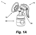
図1は、本開示による例示的な搾乳器1を、斜視図で概略的に示す。搾乳器1は、真空ポンプ10と、連結器30と、例えば哺乳瓶である集乳器50と、第1の例示的な実施形態の乳房インターフェース70とを含む。
FIG. 1 schematically illustrates an exemplary breast pump 1 according to the present disclosure in a perspective view. The breast pump 1 includes a
連結器30は、第1のチャネル34を画成する第1の略垂直に延在する管状セグメント32と、第1の管状セグメント32から斜めに及び/又は外側に延在し、第1のチャネル34と流体連通する第2のチャネル38を画成する第2の管状セグメント36とを含む。第1の管状セグメント32の下端において、連結器30は、集乳器50とのねじ込み接続のための内側ねじ山を有するねじ込みソケット40を含み、集乳器50の上端には、相補形の外側ねじ山が設けられている。第1の管状セグメント32の反対側の上端は、第1のチャネル34及び第2のチャネル38に真空を与える真空ポンプ10に接続される。真空ポンプ10は、図示される実施形態にあるように、手動の真空ポンプであっても、電気的真空ポンプであってもよく、真空ポンプ自体は、従来のデザインであり、本明細書では説明されない。第2の管状セグメント36の外側端は更に、真空ポンプ10と、集乳器50と、乳房インターフェース70とが連結器30を介して空気圧連結する一方で、集乳器50と乳房インターフェース70との間で流体連通が可能であるように、乳房インターフェース70の後端を、圧入式に受容する受容路42を画成する。当然ながら、搾乳器1の様々な実施形態は、上記され、図示されたものとは異なる形状及び構造を有する連結器30を含んでもよく、また、特に真空ポンプ10及び集乳器50を連結器30に接続するために使用される接続の種類は、例えばねじ山、スナップ式等の任意の適切なタイプであってよい。
The
概念的に、乳房インターフェース70は、2つのコンポーネント、即ち、フレキシブルライナー100と、頑丈で比較的硬く、即ち、剛性のライナー支持フレーム200とを含む。ライナー100及びライナー支持フレーム200は、通常は、2つの別個の構造コンポーネントとして形成され、これらは、使用時には、乳房インターフェース70を形成するように合せて組み立てられる必要があり、また、コンポーネントのうちの片方を洗浄及び交換し易くするために、後に、分解されてもよい。しかし、ライナー100及びライナー支持フレーム200は、乳房インターフェース70の構造部品の数を少なくするように、或いは、単一の構造コンポーネントとして一体に形成される(例えばコモールドされる)ことも考えられる。
Conceptually, the
以下、本開示による乳房インターフェース70のライナー100及びライナー支持フレーム200の構造について説明される。まず、図1乃至図4に示される乳房インターフェース70の第1の例示的な実施形態のライナー100及びライナー支持フレーム200について、幾つかの考えられる変形態様も考慮しながら、説明される。続いて、図5、図6及び図7をそれぞれ参照して、乳房インターフェース70の特に有利な第2の、第3の及び第4の例示的な実施形態について説明される。
In the following, the structure of the
ここでは、特に図2及び図3を参照する。ライナー100は、3つの、通常は、一体に形成されるセクション、即ち、前部セクション110、中間セクション140、及び、後部セクション170を含む。各セクションは、各セクションを画成する少なくとも1つの壁部を含む。
Here, reference is made in particular to FIGS. The
ライナー100の前部セクション110は、後方向にテーパする略円錐又はカップ状の前壁部112を含み、当該前壁部112は、前部開口116aを境界付ける前部の径方向外側の円周エッジ114aと、中央後部開口116bを境界付ける後部の径方向内側の円周エッジ114bとの間で延在する。円周エッジ114a、114bの間で軸方向に、前壁部112の前面112aは、略円錐状の乳房接触面118を画成する。
The
ライナー100の前部セクション110は更に、環状基部壁部122を含む。環状基部壁部122は、前壁部112の背面112bに、前部円周エッジ114aと後部円周エッジ114bの径方向位置間の径方向位置において、接続し、前壁部112の背面112bから、後方方向に延在する。したがって、これらの環状接合部に沿って、前壁部112は、環状(乳)逆流バリア120が形成されるように、基部壁部122を越えて径方向内側に延在すると見なされる。
The
前部セクション110は、環状リップ壁部124も含む。環状基部壁部122と同様に、環状リップ壁部124は、前壁部112の背面112bに、前部円周エッジ114aと後部円周エッジ114bの径方向位置間の径方向位置において、接続し、前壁部112の背面112bから、後方方向に延在する。環状リップ壁部124及び環状基部壁部122は、互いに円周方向において平行に延在する。環状リップ壁部124は、径方向外側のリップ壁部124と径方向内側の基部壁部122との間に、環状溝126が画成されるように、より大きい動径座標において延在する。環状溝126は、ライナー支持フレーム200の前部リング204(図2C及び図2Dを参照)を受容係合し、したがって、前部リング204の(略径方向の)幅に等しい又は当該幅よりも僅かに小さい(略径方向の)幅を有する。
The
使用中、ライナー100の前部セクション110は、円錐状の前壁部112によって境界付けられる内部空間が乳房の容器として機能を果たすように、女性の乳房に置かれ、乳房は、この内部空間内に少なくとも部分的に受容される。乳房の乳輪及び乳首、又は、少なくとも乳首は、前壁部112にある中央後部開口116bを通り突出する一方で、乳房接触面118は、乳房がライナー100のより奥に挿入又は吸い込まれないように、乳房の乳輪の周囲部分に当接する止め具として機能する。
In use, the
ライナー100の前部セクション110は、使用中にその形状を実質的に維持するように構成される。即ち、前部セクション110は、著しく変形することを意図していない。しかし、ライナー100の上記された中間セクション140は、動作中に乳房の乳首上に左右対称に凹むように構成される。中間セクション140は、前部セクション110(の基部壁部122)の後端に接続される。ライナー100の中間セクション140が、制御されたやり方で、確実に左右対称に凹むのを促進するように、ライナー100の前部セクション110の環状溝126と、その中に受容されるライナー支持フレーム200の前部リング204とは、異なる円周形状を有する。形状の違いは、乳房インターフェース70の組立ての際に、前部リング204は環状溝126に挿入され、前部セクション110(したがって、そこに接続されている中間セクション140)は、第1の径方向に沿って伸張され/広げられ、第1の径方向に実質的に垂直な第2の径方向に沿って圧縮される/狭くされるような違いであることが好適である。
The
一実施形態では、例えば環状溝126は、円形の円周形状を有する一方で、ライナー支持フレーム200の前部リング204は、楕円形状を有する。前部リング204の楕円形状は、長軸及び短軸の観点から説明される。これらの軸は共に、乳房インターフェース70のコンテキストでは、径方向に延在する軸である。これは、乳房インターフェース70の長手軸Lに垂直に延在するからである。長軸は、円形溝の直径よりも僅かに大きい長さを有する一方で、短軸は、円形溝の直径よりも僅かに小さい長さを有する。したがって、ライナー100の前部セクション110は、環状溝126内に前部リング204が挿入されると、圧縮応力が掛けられる。つまり、前部セクション110は、楕円形の前部リング204の長軸に沿って伸張され、前部リング204の短軸に沿って圧縮される。前部セクション110、したがって、そこに接続される中間セクション140のこの圧縮応力は、短軸に沿った中間セクションの左右対称の圧潰を促進する。
In one embodiment, for example, the
環状溝126と楕円形前部リング204とを含む乳房インターフェース70の上記実施形態の欠点は、ライナー100の中間セクション140の特定の壁剛性分布との前部リング204の短軸及び/又は長軸の回転位置ずれの影響を受けやすい点である。以下において明確にされるように、ライナー100の中間セクション140は、その壁部に、細長い、比較的剛性の部分146(例えばリブ)を含む。リブ146は、中間セクション140の両側の壁部142、144上に延在し、ライナーの内部180が排気された時に、ライナー100の制御された左右対称の圧潰を促進する。このようなリブ146を含む一実施形態では、中間セクション140のリブは、2つの特徴、即ち、壁剛性分布と、円形の環状溝126と楕円形の前部リング204との形状差異とである2つの特徴が、左右両側の圧潰をもたらす際に、互いに協働し、強化するように、前部リング204の長軸と回転位置合わせされることが好適である。しかし、乳房インターフェース70の組立ての際、ライナー支持フレーム200の前部リング204の主軸及び短軸は、例えば前部リングの短軸がリブと回転位置合わせされるように、ライナー100の中間セクション140の壁剛性分布と容易に位置ずれし、これは、2つの特徴が、互いの意図された効果を妨害してしまう。
A disadvantage of the above embodiment of the
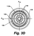
可能な位置ずれの問題を防止するために、乳房インターフェース70の好適な実施形態は、その前部セクション110がx個の対称軸(を有する円周形状)を有する環状溝126を含むライナー100と、y個の対称軸(を有する円周形状)を有する環状前部リング204を含むライナー支持フレーム200とを特徴とする。このとき、x<yである。このような好適な実施形態では、壁剛性分布に関連する非対称性と、ライナーの制御された左右両側の圧潰を促進する環状溝126と前部リング204との形状差異とは共に、製造時にライナー100に組み込まれ、これは、組立て時におけるユーザによるライナー100とライナー支持フレーム200との可能な回転位置ずれの問題を未然に防ぐ。1つの好適な実施形態では、例えばライナー100は、例えば楕円形(2つの対称軸)又は長円形(1つの対称軸)である非円形の環状溝126を含む前部セクションを有し、ライナー支持フレーム200は、当該溝に挿入するための円形の前部リング204(無限の対称軸)を有する。図3に、このようなライナー実施形態100が示される。図3Dの背面図には、楕円形の環状溝126の長軸Amaj及び短軸Aminと、中間セクション140の壁部142、144に延在する2つの向かい合うリブ146とが特定されている。図面から分かるように、楕円形の環状溝126の短軸Aminは、リブ146が離間されている方向と回転位置合わせされ、これにより、ライナー支持フレーム200の前部リング204のライナー100の前部セクション110の環状溝126内への挿入が、ライナーに短軸Aminに沿って圧縮応力を掛け、長軸Amajに沿ったライナーの圧潰を促進する。別の実施形態では、ライナーは、長方形で、非正方形の溝(2つの対称軸)を含む前部セクションを有し、ライナー支持フレームは、正方形の前部リング(4つの対称軸)を有してもよい。
In order to prevent possible misalignment problems, the preferred embodiment of the
一般に、ユーザが、操作時に、乳房、具体的には、乳首を観察できることが望ましい。このために、ライナー100は、透明である一方で、ライナー支持フレーム200は、以下により詳細に説明されるように、ライナー支持フレーム内部空間202の視覚検査を可能とするようにアクセス窓212を画成するアーム210a、210bを有する開放フレーム構造体を含んでもよい。しかし、ライナー支持フレーム200のアーム210a、210bが、偶然に、ライナー100の中間セクション140の壁部の圧潰しない部分に、回転位置合わせされた場合、アーム210a、210bは、壁部のこれらの圧潰しない部分を介した乳房の良好な視界を妨げる。圧潰しない壁部分が、アクセス窓212の前に、明白に位置決めされるように、ユーザが乳房インターフェース70を組み立てるのに役立つように、ライナー100、特にその前部セクション110には、少なくとも1つのマーク128が設けられていてもよい。マーク128は、組立ての際に、ライナー支持フレーム200のアーム210a、210bと回転位置合わせされる。当然ながら、マーク128は、マーク128のアーム210a、210bとの回転位置合わせが、アクセス窓212を介する壁部の圧潰しない部分の望ましい視認性がもたらされるように位置付けられるべきである。一実施形態では、ライナー100上のマーク128の数は、ライナー支持フレーム200のアーム210a、210bの数と一致してもよく、これにより、各マーク128は、対応するアーム210a、210bと位置合わせされる。マーク128は、ライナー100の外側にエンボス加工された矢じり、又は、マークが位置合わせされる必要のあるアーム210a、210bの(接線方向)幅と略等しい(接線方向)幅を有する隆起された表面部分といった様々な形態であってよい。
In general, it is desirable for the user to be able to observe the breast, specifically the nipple, during operation. To this end, the
原則的に、前壁部112によって画成される中央後部開口116bは、任意の適切な円周形状を有してよい。一実施形態では、例えば中央後部開口116bは円形である。しかし、円形の中央後部開口は、幾つかの欠点を有する。1つのそのような欠点は、操作中、搾乳器1は、女性の乳房に真空を印加することがあるという事実に関連する。この真空は、乳房の皮膚、特に、皮膚が中央後部開口116bの円形の円周エッジ114bに接触する場所の発赤を引き起こす。乳房に付いた円周エッジ114bの赤みを帯びた跡は、白癬といった真菌感染症の兆候として誤って受け取られてしまうことがある。円形の中央後部開口のもう1つの欠点は、逆流バリア120及び基部壁部122によって画成されるアンダーカットが著しい場合がある点である。これは、製造時のモールドからのライナー100の取り外しと、使用後のライナーの適切な洗浄との両方を妨げる。
In principle, the central
これらの欠点を解決する又は少なくとも軽減するために、ライナー100の好適な実施形態は、非円形の形状を有する中央後部開口116bを画成する前壁部112を含む。中央後部開口部116bは、例えば図3Cに明らかに示されるように、5枚の花びらを有する花といった花の形状を有する。例えば図3Cに示されるものとは花びらの数が異なる及び/又は花びらの形状が異なる様々な花の形状、又は、星形といった全く異なる形状が使用されてもよい。中央後部開口116bの円周エッジ114bの形状の径方向における変動によって、非円形の開口は、概して、乳房に赤みを帯びた円形の跡が付くことを阻止し、アンダーカットをよりアクセスし易くすることによって、アンダーカットを洗浄し易くする。中央後部開口116bの非円形の形状は、外観があまり機械的でなく、搾乳器1を使用する女性に装飾的及び魅力的に見えるという追加のメリットを提供する。
In order to overcome or at least mitigate these drawbacks, a preferred embodiment of the
ライナー100の中間セクション140は、2つの壁部、即ち、(i)S字形曲線を有する接続壁部142と、(ii)後部のテーパする漏斗状壁部144とを含む。S字形曲線を有する接続壁部は、前部セクション110の基部壁部122(の後端)を、中間セクション140の漏斗状壁部144の広い前端に接続する。
The
中間セクション140によって境界付けられる内部空間180は、圧力チャンバを画成する。使用時、搾乳器1の真空ポンプ10は、圧力チャンバ180に真空を印加し、これにより、ライナー100の中間セクション140が、交互に、(i)乳房の乳首上に圧潰し、(ii)その弛緩形状を再確立する又はその弛緩形状に戻るように広がる。
An interior space 180 bounded by the
S字形曲線を有する接続壁部142は、圧力チャンバ180が真空の影響を受ける時の中間セクション140の圧潰と、真空が除去された場合のその弛緩形状の再確立との両方を容易にする働きをする。S字形曲線を有する接続壁部は、その名称の由来が、その長手方向の断面形状(弛緩状態における)にある。当該長手方向の断面形状は、図2Cにおいて最もよく見えるように、S字形曲線、即ち、二重曲げ又は二重ひだを規定する。S字形曲線は、ライナー100の前部セクション110の基部壁部122(の後端)にすぐ隣に配置され、ライナー100の長手軸Lの周りに回転対称である。S字形曲線を有する接続壁部142は、事実上、圧力チャンバ180が真空の影響を受ける時に、ライナー100の中間セクション140が容易に変形し、したがって、内側に圧潰することを可能とする余分の壁部材料を提供する。更に、S字形曲線を有する接続壁部142は、圧力チャンバ180内の真空が取り消されると、その弛緩形状に戻るように変形するように構成される。
The connecting
ライナー100の中間セクション140は、後部から前部にかけて生じる、乳首へのその安全で、繰り返し可能で、左右両側での蠕動性の圧潰を確実とするように構成されることが好適である。このような圧潰を確実とすることに役立つように、中間セクション140の一方又は両方の壁部142、144は、長手軸Lの周りに2回転対称を有する剛性分布を有する。このために、壁部142、144は、例えば、対応する壁部142、144に沿って又は対応する壁部142、144内で、略径方向/長手方向に延在する例えば壁部の比較的剛性部分である細長いリブ146を含む。一実施形態では、このようなリブ146は、壁部の比較的厚い部分によって形成され、これは、ライナー100が、単一の均質材料、又は、少なくとも、ライナー100の壁部全体に亘って一様である弾性係数を有する材料から製造できるという利点を提供する。別の実施形態では、リブ146は、相互に異なる弾性係数を有する少なくとも2つの構成材料を使用して実現されてもよい。このような実施形態では、リブ146は、第1の構成材料で作られる一方で、S字形曲線を有する壁部142及び/又は漏斗状壁部144の隣接する又は周囲の部分は、第1の構成材料の弾性係数よりも小さい弾性係数を有する第2の構成材料で作られる。
The
図3に示されるライナー100の実施形態では、ライナーの中間セクション140は、S字形曲線を有する接続壁部142と漏斗状壁部144との両方の壁部の比較的厚い部分によって画成される2つの(接線方向に)広く、(長手方向に)細長いリブ146を含む。リブ146は、中間セクション140の直径方向において両側に位置付けられる。使用時、真空が圧力チャンバ180に印加されると、壁部142、144のリブ付き部分は、その直径方向において両側にあるリブなし部分よりも多くの圧潰に対する抵抗を提供し、これにより、リブなし部分の互いに向かう左右両側の圧潰の方が好まれる。
In the
ライナー100の後部セクション170は、略軸方向に延在する管状又はパイプ状壁部を含み、ライナーの中間セクション140の漏斗状壁部144によって画成される漏斗の延長部を形成すると見なされる。したがって、中間セクション140の漏斗状壁部144の後端は、後部セクション170の管状壁部の前端に接続される。
The
ライナー100の後部セクション170の管状壁部は、原則的に、任意の内側及び/又は外側横断面を有する。例えば図2乃至図4に示されるライナー100の第1の例示的な実施形態は、略円形の内側及び/又は外側横断面を有する後部セクション170を有する。或いは、後部セクション170の管状壁部は、図7に示される第4の例示的な実施形態にあるように、例えば略ティアドロップ形の内側及び/又は外側横断面を有してもよい。1つの対称軸を有し、(長円形とは異なり)曲線の広い部分がその狭い部分に合流するところで排他的に凸状ではない滑らかな平面閉曲線によって画成されるティアドロップ形状は、操作時のライナー100の上記の左右両側の圧潰を支援する。ティアドロップ形状の内側断面を含む管状後部セクション170を有するライナー100の一実施形態では、ティアドロップ形状の細い部分が、乳房から搾り出された乳を集乳器50へ導く乳用の溝の機能を果たす。このような実施形態では、ティアドロップ形状の横断面の細い部分の(ティアドロップの対称軸に沿って測定される)長さは、ティアドロップ形状の横断面の細い部分によって画成される乳用の溝が、後方への軸方向において深くなる、即ち、下方向に傾斜するように、後部セクション170の後方への軸方向において増加する。
The tubular wall of the
後部セクション170は更に、1つ以上の外部の、概して環状のフランジを含む。フランジは、管状壁部と一体に形成され、そこから径方向外側に延在する。第1のフランジ172は、管状壁部の後端に設けられる。第2のフランジ174は、第1のフランジ172の前に設けられ、第1のフランジ172から、又は、少なくとも管状壁部の後端から、軸方向に離間される。両フランジ172、174は、以下に説明されるライナー支持フレーム200の後部リング206の内径よりも大きい外径を有する。第1のフランジ172及び第2のフランジ174の両方を含む実施形態において、それらの間の軸方向の間隔は、通常、ライナー支持フレーム200の後部リング206の軸方向の長さと一致する。第2のフランジ174は、通常、第1のフランジ172よりも幾分(軸方向において)広く、及び/又は、(径方向において)高い。以下、「シーリングリップ」及び「フィンガグリップリング」とそれぞれ呼ばれる第1のフランジ172及び第2のフランジ174の機能は、乳房インターフェース70の組立てについて説明される以下において明らかにされる。
The
ライナー100は、例えば熱可塑性エラストマー、ゴム、ラテックス又は液状シリコーンゴム(LSR)といったフレキシブルで、好適には弾性を有する材料から一体部品として製造される。一実施形態では、ライナー100は、射出成形を介して製造される。この処理では、ライナーは、その弛緩状態で固定又は硬化される。ライナー材料は透明であってよく、これにより、女性が、使用時に、ライナー100の中で何が起きているのかを視覚的に観察することができる。
The
次に、ライナー支持フレーム200の構造の説明に移る。図4A乃至図4Cは、それぞれ、図2A乃至図2Dに示される乳房インターフェース70の第1の例示的な実施形態のライナー支持フレーム200を、斜視図(図4A)、側面図(図4B)及び正面図(図4C)で概略的に示す。
Next, the description will proceed to the structure of the
その名称が示すように、ライナー支持フレーム200は、ライナー100に機械的な支持を提供する働きをする。このために、ライナー支持フレーム200は、ライナー支持フレーム内部空間202を画成し、その中に、乳房インターフェース70の組み立てられた状態において、ライナー100が(外部から)ライナー支持フレーム200によって係合され、嵌めこまれるように、ライナー100の少なくとも一部を受容することができる。図2A乃至図2Dを参照されたい。その支持機能を果たすために、ライナー支持フレーム200は、その構造が実質的に剛性であり、操作時に、大きく変形することなく、ライナー100によってそこにかかる任意の力に耐えることができるように(ライナー100に比べて)比較的硬い材料から作られる。ライナー支持フレーム200は、例えば射出成形されたプラスチックといった任意の適切な材料から製造されてもよい。
As the name implies, the
ライナー支持フレーム200は、透明であってもよいし、透明又は非透明のライナー100と組み合わせて使用されてもよいが、透明なライナー100と不透明なライナー支持フレーム200との組み合わせが、ユーザ機能性を最大にし、2つの部品間のコントラストを最適にする。このコントラストによって、ユーザが乳房インターフェース70を組立て、組立ての正確さを確認する能力を高める。
The
ライナー支持フレーム200は、2つの軸方向に離間されたリング、即ち、前部リング204と後部リング206とを含む。なお、明確にするために、本テキストにおいて使用される「リング」との用語は、広く解釈されるべきである。当該用語は、典型的には円形であるが、非円形(例えば多角形)であってもよいその円周形状に関係なく、任意の連続的又は不連続的/分割された環状要素を包含することを意図している。2つのリング204、206は、少なくとも1つの比較的硬く、略軸方向に延在するアーム又はストラットによって相互に接続される。図4A乃至図4Cの第1の例示的な実施形態では、ライナー支持フレーム200は、2つの硬いが、弾力のあるアーム210a、210bを含む。これらのアームは、構造上同一である。前部リング204は、通常、後部リング206よりも大きい内径及び外径を有する。したがって、複数のアーム210a、210bを有する実施形態では、2つのリング204、206を相互接続するアーム210a、210bは、前部リング204から、後方方向において、後部リング206に合流すると見なされる。後部リング206の内径は、ライナー100の管状後部セクション170の外径に合せられる。即ち、当該外径に略等しい。後部リング206は、連結器30との真空気密接続を可能とするように、管状後部セクション170を嵌めるように受容する(図2A乃至図2Dを参照)。
図4A乃至図4Cの第1の例示的な実施形態において見られるように、ライナー100の前部セクション110における環状溝126に受容されるように構成される前部リング204は、単一の部品で、連続的又は閉リングである(前部リングが分割されている図5及び図6の第2及び第3の例示的な実施形態と比較されたい)。前部リング204の略軸方向の長さは、乳房インターフェース70の組み立てられた状態において、前部リング204の後端(アーム210a、210bとの接合部は無視する)が、壁部122、124のうちの少なくとも一方、即ち、リップ壁部124の後端及び基部壁部122の後端のうちの少なくとも一方と実質的に同一平面にあるように、環状溝126を画成する壁部122、124の少なくとも一方の略軸方向の長さに一致することが好適である。図示される実施形態では、図2Dの側断面図において最もよく見えるように、前部リング204の後端は、基部壁部122の後端と同一平面に位置する。組立ての際、これらの後端の面一性は、前部リング204の環状溝126への挿入が完了したことを知らせる合図をユーザに提供する。
As seen in the first exemplary embodiment of FIGS. 4A-4C, the
ライナー100の管状後部セクション170に嵌るように、また、場合により、締め付けるように構成される後部リング206は、後部リング206自体が後部セクションの2つのフランジ172、174の間で軸方向にぴったりと受容可能であるように(図2A乃至図2Dを参照)、分割された又は二重不連続リングであることが好適である。つまり、後部リング206は、後部リングを少なくとも2つの実質的に剛性の相補形の円周部分に分割する少なくとも2つの円周不連続部を含む。相補形の円周部分は、後部リング206の断面開口/通路領域が、一時的に拡大されるように、移動可能であり、したがって、互いに対し再配置可能であり、任意選択的に、互いから取り外すことも可能である。図4A乃至図4Cの第1の例示的な実施形態では、例えば後部リング206は、当該リングを2つの別個の相補形の半体206a、206bに分割する実際の割れ目又はスリットの形態の2つの円周不連続部を有する。図5及び図6の第2及び第3の実施形態を参照するに、これらの実施形態は共に、分割された後部リング206を同様に含む。図6の実施形態を考慮すると、相補形の後部リング部分を接続する、図6におけるフォイルヒンジ201といったヒンジが、概して円周不連続部を形成すると見なされる。これは、ヒンジは、後部リング206の円周形状の画成に貢献する場合であっても、その(内)周に沿って、後部リングの実質的な剛性の不連続部を表すからである。即ち、ヒンジは、2つの実質的に剛性の相補形の円周後部リング部分を、それらの空間的再配置を可能とするために、意図的に接続するに過ぎないからである。
A
図4A乃至図4Cの第1の例示的な実施形態において見られるように、各相補形の後部リング部分206a、206bは、様々なアーム210a、210bを介して、前部リング204に接続される。ライナー支持フレーム200は、比較的硬いが、この分割後部リング構造は、後部リングの相補形の円周部分206a、206bが(各アーム210a、210bによって加えられる適度な径方向内側へのバネ作用に逆らって)径方向/接線方向に離れることを可能とすること(これにより、各アーム210a、210bは、径方向外側に動く)によって、乳房インターフェース70の組立てを容易にし、これにより、ライナー100の管状後部セクション170を、円周部分の間で、軸方向に通す作業を簡単にする。これは、特に、ライナー100の管状後部セクション170の後部端にフランジ又はシーリングリップ172を含む実施形態において、言えることである。
As seen in the first exemplary embodiment of FIGS. 4A-4C, each complementary
分割後部リング206における上記された少なくとも2つの円周不連続部は、当該リングを2つの相補形の部分206a、206bに分ける対応する割れ目208によって形成される。割れ目208は、図示される実施形態において見られるように、同一の形状を有してよいが、これは必須ではない。2つの相補形の円周後部リング部分206a、206b間の割れ目208の形状は、基本的には任意の形状を有してもよい。一実施形態では、割れ目の形状は、真っ直ぐ又は線形である。しかし、真っ直ぐな割れ目形状は、後部リング206の相補形の円周部分206a、206b間の相対的な軸方向の移動を容易にしてしまうという欠点があり、これは、ライナー支持フレーム200における望ましくない機械的応力につながる。このような比較的軸方向の移動は、特に、乳房インターフェース70の搾乳器1への接続の際に生じる。即ち、乳房インターフェース70の後端が、連結器30の受容路42内に押し込まれる時に生じる。真っ直ぐな割れ目形状のもう1つの欠点は、後部リング206が、偶然に壊れたかのように見える点である。これらの欠点を解決するために、割れ目の形状は、図示される実施形態に示されるように、略C字形である。滑らかなC字形の割れ目形状は、相補形の後部リング部分206a、206bの正しい相対的な軸方向の位置合わせを維持するのに役立ち、後部リング206が誤って壊れていると見られないように、意図する通りに見える。
The at least two circumferential discontinuities described above in the split
後部リング206の(径方向)内面は滑らかである。しかし、滑らかな内面は、例えばシリコーン製のライナー100の後部セクション170と後部リング206との間の摩擦を促進することが分かっており、これは、乳房インターフェース70の組立てを複雑にする可能性がある。ライナー100の後部セクション170と後部リング206の内面との間の摩擦を減少させるために、内面には、例えばマット仕上げを有するように表面テクスチャが施される。表面テクスチャは、スパーク(sparked)仕上げであってもよい。
The inner surface (in the radial direction) of the
合わせて、ライナー支持フレーム200のアーム210a、210bも、ライナー支持フレーム200のライナー支持フレーム内部空間202を完全に接線方向又は円周方向において包囲しないことが好適である。ライナー支持フレーム内部空間202を共に完全に包囲するアーム210a、210bは、乳房インターフェース70の組立て及び組立て分解を妨げる場合があり、また、使用中におけるユーザのライナー100の視野を遮る可能性がある。当該視野は、特にライナーの圧潰の過程に関する情報、また、透明のライナーを使用する実施形態では、乳首の配置及び乳の流れに関する情報を提供する。したがって、ライナー支持フレーム200のアーム210a、210bのうちの少なくとも一方が、少なくとも1つのアクセス窓212を画成することが好適である。より具体的には、2つの接線方向の隣接するアーム210a、210bは共に、それらの間に(接線方向に)アクセス窓121を画成し、当該アクセス窓212は、ライナー支持フレーム内部空間202への手動及び視覚的アクセスを可能にする。図4A乃至図4Cに示されるライナー支持フレーム200の実施形態は、ライナー支持フレーム200の両側に2つのこのようなアクセス窓を有する。組立ての際に、1つのアクセス窓212は、ライナー支持フレーム内部空間202の視覚的な観察のために使用され、もう1つのアクセス窓212は、そこへの手動アクセスのために使用される。
In addition, it is preferable that the
ライナー支持フレーム200のロバスト性を高めるために、各アーム210a、210bと前部リング204との接合部又は接続部は、各アームと後部リング206との接合部よりも(接線方向に)広いことが好適である。したがって、アーム210a、210bの(接線方向の)幅は、後方方向にテーパする。これに加えて又は代えて、前部リング204における接合部は、例えば前部リング204の半径の少なくとも半分である曲率半径である比較的大きい曲率半径216を規定することが好適である。このような大きい半径は、アーム210a、210bの屈曲に対する剛性を増加させ、したがって、使用時に、乳房インターフェース70が垂れた感じがあまりしない。
In order to increase the robustness of the
ライナー支持フレーム200のアーム210a、210bが、その後部リング206に接合する場所において、段部220が画成されることが好適である。段部220は、角度の比較的急激な変化によって特徴付けられる。段部220は、乳房インターフェース70の後部の搾乳器1の連結器30内の受容路42への挿入の際に、連結器の外面に対抗して付勢される止め部として働く。段部220があることによって、ユーザが、乳房インターフェースの後部を、連結器にある受容路42内に、段部220が連結器に当接する点まで付勢することを促し、これにより、乳房インターフェース70と連結器30との間に適切な真空シールが実現され、また、乳房インターフェース70の分割後部リング206が、定位置に固定され、ライナー支持フレーム200にその剛性の一部が提供される。
Preferably, the
ライナー支持フレーム200のアーム210a、210b各々には、ライナー100の後部セクション170にある第2のフランジ174と協働するフランジ相互作用部材222が設けられている。フランジ相互作用部材222は、それが設けられているアーム210a、210bの内面から内側に突出する。長手方向の側断面図(図2Cを参照)において見られるように、フランジ相互作用部材222は、概して鋸歯状であり、後方方向において見た場合に、径方向内側に傾斜する傾斜面224と、実質的に径方向に延在する後部止め面226とを含む。止め面226は、当該止め面226と後部リング206の前端との間に軸方向の間隙228があるように、後部リング206の前端の隣にあるが、当該前端から軸方向に離間されて配置される。ライナー支持フレームのアーム210a、210bと後部リング206との間の接合部が、段部220を画成する実施形態では、フランジ相互作用部材222の止め面226は、段部220の内側に面する。
Each
フランジ相互作用部材222は、乳房インターフェース70の第1の例示的な実施形態の組立て処理の説明から明らかとなるように、幾つかの目的を果たす。
The
乳房インターフェース70が、ライナー100と、ライナー支持フレーム200とを別個の構造コンポーネントとして含む場合、図2乃至図4の乳房インターフェースは、次の通りに組み立てられる。ユーザは、ライナー100上に設けられるマーク128が、ライナー支持フレーム200のアーム210a、210bと回転位置合わせされるように、ライナーの管状後部セクション170を、ライナー支持フレーム200の前部リング204を通して軸方向に挿入する。ユーザは、ライナー支持フレーム200に設けられたアクセス窓212のうちの1つ以上を介して指を入れ、ライナー100の後部セクション170に設けられた第2のフランジ又はフィンガグリップリング174を掴む。第2のフランジ174を掴みつつ、ユーザは、ライナー100を後方に押す又は引っ張る。その際に、第2のフランジ174は、アーム210a、210bの内面に設けられたフランジ相互作用部材222に接触する。その結果、ライナー支持フレーム200のアーム210a、210bは、ライナー100が更に後方に動かされるのにつれて、径方向に離れるように徐々に広がるようにされる。アーム210a、210bの広がりは、ライナー支持フレーム200の分割後部リング206の相補形の円周部分206a、206bの広がりを引き起こし、これは、相補形の円周部分間で、第1のフランジ172を通過し易くする。第2のフランジ174が、フランジ相互作用部材222の止め面226の軸方向の位置に到達すると、第2のフランジは、止め面226と後部リング206の前端との間の軸方向の間隙228内に嵌り込む。同時に、2つのアーム210a、210bは、相補形の円周後部リング部分206a、206bが、第1のフランジ172と第2のフランジ174との間に延在するライナー100の管状後部セクション170の一部分に嵌合係合するように、再び弛緩し、互いに向かって動く。これは、少なくとも後端において、ライナー100のライナー支持フレーム200への挿入が完了したという視覚的確認をユーザに提供するだけでなく、シーリングリップ172及びフィンガグリップリング174、従って、ライナー100も、更なる軸方向の移動に対して係止する。組立てを完了するために、ユーザは、ライナー支持フレーム200の前部リング204が、ライナー100の前部セクション110における環状溝126にきっちりと受容されたことを確認し、また、必要に応じて、好適には、前部リング204が、環状溝126を画成する壁部122、124の少なくとも一方の後端と同一平面であるように、前部リング204の環状溝126への適切な配置を確実にしてもよい。
If
乳房インターフェース70自体が組み立てられると、その後部、具体的には、ライナー100の管状後部セクション170とライナー支持フレーム200の後部リング206とは、搾乳器1の連結器30によって提供される受容路42内に挿入される。受容路42は、適切な真空シーリングが実現されるように、乳房インターフェース70の後部が圧入受容されるような寸法にされることが好適である。
When the
乳房インターフェース70と連結器30との間の第1の真空シールが、シーリングリップ172と、受容路42の内面との間に形成される。このために、シーリングリップ172の外径は、受容路42の内径よりも僅かに大きいことが好適である。ライナー材料の柔軟性によって、シーリングリップ172は、乳房インターフェース70の後部の受容路42への挿入時に変形する。これにより、シーリングリップ172の外周と、受容路42の内周との間の形状における差異が調整され、効果的な真空シールが生成される。第2の真空シールが、分割後部リング206の外面と、受容路42の内面との間に形成される。この第2の真空シールを実現するために、2つの、通常、剛性であるコンポーネント42、206の表面は、実質的に形状が同一である必要があり、例えば同じ直径、テーパ等を有さなければならない。シーリングリップ172及びフィンガグリップリング174が、それらの間で軸方向において後部リング206に係合するにつれて、第3の真空シールが、フィンガグリップリング174との協働によってシーリングリップ172によって形成されてもよい。
A first vacuum seal between the
図1乃至図4を参照して、乳房インターフェース70の第1の例示的な実施形態について説明した。次に、幾つかの特定の及び有利な変形態様を示す幾つかの更なる例示的な実施形態に注目する。
A first exemplary embodiment of the
なお、図1乃至図4の第1の例示的な実施形態のライナー支持フレーム200は、単一部品コンポーネントであるが、代替実施形態のライナー支持フレーム200は、複数の取り外し可能に接続可能な部品を含んでもよい。
It should be noted that while the
一実施形態(図示せず)では、例えば前部リングと後部リングとを相互接続する少なくとも1つのアームは、実質的にアームの全軸方向長さに亘って、ライナー支持フレームの長手軸に対し120°〜180°の範囲の角度に対応する。このような広い、「ハーフパイプ」アームは、追加のアームを不必要にする十分な剛性を有するクレードル状のライナー容器を提供する。このような実施形態では、前部リング204及び/又は後部リング206は、2つの取り外し可能に接続可能な相補形の円周部分を含む。各リングについて、相補形の円周部分のうちの一方は、ハーフパイプアームと一体にされ、もう一方は、例えばクリップの形で、ハーフパイプアームに取り外し可能に接続可能である。後者のリング部分の分離された状態では、ライナー100の前者のアームが取り付けられた部分への挿入が容易にされる一方で、両部分の閉じた状態では、ライナーは、両部分間の適切な位置にしっかりと保持される。
In one embodiment (not shown), for example, at least one arm interconnecting the front ring and the rear ring is substantially relative to the longitudinal axis of the liner support frame over the entire axial length of the arm. It corresponds to an angle in the range of 120 ° to 180 °. Such a wide, “half-pipe” arm provides a cradle-like liner container with sufficient rigidity that does not require an additional arm. In such an embodiment, the
図5の第2の例示的な実施形態といった後者の実施形態を更に詳細に説明するために、ライナー支持フレーム200全体が、2つの取り外し可能に接続可能な部分又は半体200a、200bに分割されてもよい。図示されるように、この実施形態では、前部リング204及び後部リング206が共に分割され、各リング204、206は、第1のアーム210aに固定して接続される1つの部分204a、206aと、第2のアーム210bに固定して接続されるもう1つの相補形の部分204b、206bとを有する。乳房インターフェース70の組立ての際に、2つのフレーム部分又は半体200a、200bは、具体的には、(i)前部リング部分204a、206bを、ライナー100の環状溝126内に位置付けることによって、また、(ii)その後部リング部分206a、206bの後端を、シーリングリップ172に接して、場合により、シーリングリップ172により画成される環状溝173(図6A参照)内に位置付けることによって、順々に、ライナー100と係合される。続いて、乳房インターフェース70は、搾乳器1の連結器30によって提供される受容路42内に圧入される。
To describe the latter embodiment in more detail, such as the second exemplary embodiment of FIG. 5, the entire
図5の2パートライナー支持フレーム200は、乳房インターフェース70の組立ての際に、シーリングリップ172を、後部リング206を通して挿入するためにユーザがかなりの力を加える必要をなくすが、ライナー支持フレーム200のマルチパートデザインは、フレームの様々な部品が一緒に保持されず、気が付かないうちに紛失する可能性があるという欠点を有する。この問題を回避するために、ライナー支持フレームの2つの相補形の半体200a、200bは、取り外し可能に接続可能であるようには作られず、その代わりに、図6の第3の例示的な実施形態にあるように、例えばフォイルヒンジ201によって、ヒンジを介して接続されてもよい。
The two-part
図7A及び図7Bは、本開示による乳房インターフェース70の第4の実施形態を、側断面図(図7A)及び後面斜視図(図7B)で概略的に示す。
7A and 7B schematically illustrate a fourth embodiment of a
図1乃至図4の乳房インターフェース70の第1の例示的な実施形態に関連付けられる問題は、それを使用する女性が、自身の乳房から搾り出された乳が確実に集乳器50に向かい、その中へと流れるように、前傾になる必要がある点である。1回の搾乳セッションには時間がかかり、特には30分以上にも及ぶため、前傾姿勢は不快となる。
The problem associated with the first exemplary embodiment of the
不快感の問題を解決するために、乳房インターフェース70、及び、具体的にはそのライナー100は、上部側又は頂部側及び下部側又は底部側を有する使用姿勢(use orientation)と関連付けられる。更に、ライナー100の前部セクション110は、乳房接触面118(図2Cも参照)における開口116bの平面に実質的に垂直に延在する、また、上記の使用姿勢において、実質的に水平に延在する長手軸Lfsに関連付けられる。即ち、使用時、前部セクション110の乳房接触面118が、女性の乳房に接触すると、前部セクション110の長手軸Lfsは、実質的に水平に延在する。ライナー100の構造は更に、ライナー100の中間セクション140の後方にテーパする漏斗状壁部144及び/又は後部セクション170の管状壁部171が、乳房接触面118における(乳首を受容する)開口116bから、管状壁部171の後端(乳放出)開口にまで延在し、また、上記の使用姿勢において、前部セクション110の長手軸Lfsに対して下方向に傾斜する細長い内側下部/底部表面部分171aによって少なくとも部分的に境界付けられる乳用の導管190を画成するように、適応される。後部セクション170(の底部表面部分171a)の下方向への傾斜によって、乳房から搾り出された乳は、重力の作用によって、後部セクション170の管状壁部171を通り、その後端開口に向かって、自然に流れる。したがって、女性が、使用時に前傾する必要はない。
To solve the problem of discomfort, the
この解決策によれば、乳房インターフェース70の長手軸Lは、乳房インターフェース70の当該長手軸Lが2つの真っ直ぐで位置合わせされないセクションを含むように(下方向の)キンク又は屈曲を含むことが好適である(図7Aを参照)。長手軸の第1のセクションLfsは、ライナー100の前部セクション110とライナー支持フレーム200の前部リング204とに関連付けられ、長手軸の第2のセクションLrsは、ライナー100の後部セクション170と、ライナー支持フレーム200の少なくとも1つのアーム210a、210b及び後部リング206とに関連付けられる。乳房インターフェース70の長手軸Lの2つのセクションLfs、Lrsは、約10〜45度の範囲内の角度φを含むことが好適である。後部セクション170の少なくとも管状壁部171の断面形状は、円形であるが、円形である必要はない。図示される実施形態では、例えば後部セクション170の管状壁部171は、上記され、かつ、図7Bに示されるように、(逆さまにされた)ティアドロップ形状の内側断面形状を有する。したがって、管状壁部171は、「下方向に傾斜する溝」を有する乳用の導管190である長手方向の部分を画成し、その底部は、細長い底部表面部分171aによって形成される。
According to this solution, the longitudinal axis L of the
本明細書に開示される乳房インターフェースの例示的な実施形態が、部分的に添付図面を参照して、上で説明されたが、当然ながら、本開示は、これらの実施形態に限定されない。開示された実施形態の変形態様が、当業者によって、図面、開示及び添付の特許請求の範囲の検討から、乳房インターフェースを実施する際に、理解及び実現されてもよい。本明細書全体を通して「1つの実施形態」、「一実施形態」等との言及は、実施形態に関連して説明される特定の特徴、構造又は特性が、乳房インターフェースの少なくとも1つの実施形態に含まれてもよいことを意味する。したがって、本明細書全体に亘って様々な場所において出現する「1つの実施形態では」又は「一実施形態では」との表現は、必ずしもすべて同じ実施形態を指しているわけではない。なお、1つ以上の実施形態の特定の特徴、構造又は特性は、明示的には説明されていないが新しい実施形態を形成するために、任意の適切な態様で組み合わされてもよい。同様に、1つ以上の実施形態の特定の特徴、構造又は特性は、明示的には説明されていないが新しい実施形態を形成するために、明示的に説明されている実施形態から取り除かれてもよい。例えば図7の第4の例示的な実施形態を参照して説明されたライナーの「下方向に傾斜する後部セクション」という特徴は、新しい実施形態を形成するために、説明されたどの他の実施形態に組み込まれてもよい。同様に、他の実施形態を参照して説明された特徴も、明示的には説明されていないが新しい実施形態を形成するために、第4の実施形態に含めることも考えられる。 Although exemplary embodiments of the breast interface disclosed herein have been described above, in part with reference to the accompanying drawings, it should be understood that the present disclosure is not limited to these embodiments. Variations of the disclosed embodiments may be understood and realized by those skilled in the art in implementing a breast interface from a study of the drawings, the disclosure, and the appended claims. Throughout this specification, references to “one embodiment,” “one embodiment,” and the like refer to particular features, structures, or characteristics described in connection with an embodiment in at least one embodiment of a breast interface. It may be included. Accordingly, the phrases “in one embodiment” or “in one embodiment” appearing in various places throughout this specification are not necessarily all referring to the same embodiment. It should be noted that the particular features, structures or characteristics of one or more embodiments may be combined in any suitable manner to form new embodiments that are not explicitly described. Similarly, certain features, structures or characteristics of one or more embodiments may be removed from explicitly described embodiments to form new embodiments that are not explicitly described. Also good. For example, the “downwardly inclined rear section” feature of the liner described with reference to the fourth exemplary embodiment of FIG. 7 can be used with any other implementation described to form a new embodiment. It may be incorporated into the form. Similarly, features described with reference to other embodiments may also be included in the fourth embodiment to form new embodiments that are not explicitly described.
1 搾乳器
10 真空ポンプ
30 連結器
32 第1の管状セグメント
34 第1のチャネル
36 第2の管状セグメント
38 第2のチャネル
40 第1の管状セグメントの下端におけるねじ込みソケット
42 乳房インターフェースの後端を受容するための受容路
50 集乳器
70 乳房インターフェース
100 ライナー
110 前部セクション
112 円錐状前壁部
112a 前壁部の前面
112b 前壁部の背面
114a 径方向外側の円周エッジ
114b 径方向内側の円周エッジ
116a 前部開口
116b 後部開口
118 乳房接触面
120 逆流バリア
122 基部壁部
124 リップ壁部
126 基部壁部とリップ壁部との間の環状溝
128 回転位置合わせマーク
140 中間セクション
142 S字形曲線を有する接続壁部
144 後部のテーパする漏斗状壁部
146 長手方向リブ
170 後部セクション
171 管状壁部
171a 下部内側表面部分
172 第1のフランジ/シーリングリップ
173 前方向に曲げられた第1のフランジによって画成される環状溝
174 第2のフランジ/フィンガグリップリング
180 内部圧力チャンバ
190 乳用通路
200 ライナー支持フレーム
200a ライナー支持フレームの第1の相補形の部分
200b ライナー支持フレームの第2の相補形の部分
201 (フォイル)ヒンジ
202 ライナー支持フレーム内部空間
204 前部リング
204a 第1の相補形の前部リング部分
204b 第2の相補形の前部リング部分
206 分割後部リング
206a 第1の相補形の後部リング部分
206b 第2の相補形の後部リング部分
208 リング半体間の割れ目
210a 第1のアーム
210b 第2のアーム
212 第1のアームと第2のアームとの間のアクセス窓
214 アームと前部リングとの接合部
216 アームと前部リングとの接合部における大きい半径
218 アームと後部リングとの接合部
220 段部
222 フランジ相互作用部材
224 傾斜面
226 止め面
228 止め面と後部リングの前端との間の軸方向間隙
Amaj 楕円形環状溝の長軸
Amin 楕円形環状溝の短軸
L 乳房インターフェースの長手軸
Lfs ライナーの前部セクション/フレームの前部リングの長手軸
Lrs ライナーの後部セクション/フレームのアーム及び後部リングの長手軸
R 径方向
φ 長手軸セクションLfs、Lrsによって挟まれる角度
1 breast pump 10 vacuum pump 30 coupler 32 first tubular segment 34 first channel 36 second tubular segment 38 second channel 40 screw socket 42 at the lower end of the first tubular segment Receiving path 50 for collecting breast collector 70 breast interface 100 liner 110 front section 112 conical front wall 112a front wall front 112b front wall rear 114a radially outer circumferential edge 114b radially inner circle Peripheral edge 116a front opening 116b rear opening 118 breast contact surface 120 backflow barrier 122 base wall 124 lip wall 126 annular groove 128 between base and lip wall rotational alignment mark 140 middle section 142 sigmoidal curve Connecting wall 144 with rear taper funnel Wall 146 Longitudinal rib 170 Rear section 171 Tubular wall 171a Lower inner surface portion 172 First flange / sealing lip 173 Annular groove 174 defined by forward bent first flange / second flange / Finger grip ring 180 Internal pressure chamber 190 Milk passage 200 Liner support frame 200a Liner support frame first complementary portion 200b Liner support frame second complementary portion 201 (foil) hinge 202 Liner support frame internal space 204 front ring 204a first complementary front ring portion 204b second complementary front ring portion 206 split rear ring 206a first complementary rear ring portion 206b second complementary rear ring portion 208 Split 210 between ring halves a first arm 210b second arm 212 access window 214 between the first arm and the second arm joint 216 between the arm and the front ring 216 large radius 218 at the joint between the arm and the front ring major axis a min elliptical axial gap a maj elliptical annular groove between the front end of the arm and the rear ring and junction 220 step portion 222 flange interacting member 224 inclined surface 226 stop surface 228 stop surface of the rear ring Annular groove minor axis L Breast interface longitudinal axis L fs liner front section / frame front ring longitudinal axis L rs liner rear section / frame arm and rear ring longitudinal axis R radial φ longitudinal axis section Angle between L fs and L rs
Claims (15)
前部リングと、
後部リングと、
前記前部リングと前記後部リングとが軸方向に離間されるように当該前部リングと当該後部リングとを相互接続する、少なくとも1つのアームと、
を含み、前記ライナーは、
前記ライナー支持フレームの前記前部リングに係合する、前部セクションと、
前記前部セクションに接続され、後部のテーパする漏斗状壁部を含む、中間セクションと、
前記中間セクションに接続され、前記ライナー支持フレームの前記後部リングによって嵌めるように受容される管状壁部を含む、後部セクションであって、前記管状壁部の後端には、前記ライナー支持フレームの前記後部リングの内径よりも大きい外径を有し、前記乳房インターフェースの組み立てられた状態において末端で前記後部リングに当接する、第1の環状フランジが設けられている、当該後部セクションと、
を含み、
前記後部リングは、分割された後部リングであり、前記ライナーのフランジ付きの後端の通過を容易にするために互いに対し再配置可能な、少なくとも2つの相補形の後部リング円周部分を含むことを特徴とする、乳房インターフェース。 A breast support breast interface comprising: a liner support frame defining a liner support frame interior space that receives at least a portion of the liner; and the liner, wherein the liner support frame comprises:
The front ring,
The rear ring,
At least one arm interconnecting the front ring and the rear ring such that the front ring and the rear ring are axially spaced apart;
The liner includes:
A front section engaging the front ring of the liner support frame;
An intermediate section connected to the front section and including a tapered rear funnel wall;
A rear section including a tubular wall connected to the intermediate section and received to fit by the rear ring of the liner support frame, the rear end of the tubular wall being at the rear of the liner support frame The rear section having a first annular flange having an outer diameter greater than an inner diameter of the rear ring and abutting the rear ring at a distal end in the assembled state of the breast interface;
Only including,
The rear ring is a split rear ring and includes at least two complementary rear ring circumferential portions that are repositionable relative to each other to facilitate passage of the flanged rear end of the liner. Featuring a breast interface.
前記少なくとも1つのアームは、少なくとも2つのアームを含み、
前記ライナー支持フレームは、各部分がそれぞれの前部リング円周部分と、それぞれの後部リング円周部分と、前記それぞれの前部リング円周部分と前記それぞれの後部リング円周部分とを軸方向に離間される態様で相互接続するそれぞれのアームと、を含む、少なくとも2つの取り外し可能な相補形の部分を含む、
請求項1乃至8の何れか一項に記載の乳房インターフェース。 The front ring is divided and includes at least two complementary front ring circumferential portions;
The at least one arm includes at least two arms;
The liner support frame is configured such that each part has a respective front ring circumferential part, each rear ring circumferential part, each front ring circumferential part, and each rear ring circumferential part in the axial direction. Each arm interconnecting in a spaced-apart manner with at least two removable complementary portions
Breast interface according to any one of the preceding claims.
前記少なくとも1つのアームは、少なくとも2つのアームを含み、
前記ライナー支持フレームは、各部分がそれぞれの前部リング円周部分と、それぞれの後部リング円周部分と、前記それぞれの前部リング円周部分と前記それぞれの後部リング円周部分とを軸方向に離間される態様で相互接続するそれぞれのアームと、を含む、少なくとも2つのヒンジを介して接続される相補形の部分を含む、
請求項1乃至8の何れか一項に記載の乳房インターフェース。 The front ring is divided and includes at least two complementary front ring circumferential portions;
The at least one arm includes at least two arms;
The liner support frame is configured such that each part has a respective front ring circumferential part, each rear ring circumferential part, each front ring circumferential part, and each rear ring circumferential part in the axial direction. Each arm interconnecting in a spaced-apart manner with a complementary portion connected via at least two hinges,
Breast interface according to any one of the preceding claims.
後部リングと、
前記前部リングと前記後部リングとが軸方向に離間されるように当該前部リングと当該後部リングとを相互接続する、少なくとも1つのアームと、
を含み、
ライナーの少なくとも一部を受容するためのライナー支持フレーム内部空間を規定する、請求項1乃至13の何れか一項に記載の乳房インターフェースに使用するライナー支持フレームであって、
前記後部リングは、前記ライナーのフランジ付きの後端の通過を容易にするために互いに対し再配置可能な、少なくとも2つの相補形の後部リング円周部分を含むことを特徴とする、ライナー支持フレーム。 The front ring,
The rear ring,
At least one arm interconnecting the front ring and the rear ring such that the front ring and the rear ring are axially spaced apart;
Including
Defining the liner support frame interior space for receiving at least a portion of the liner, a liner supporting frame for use in breast interface according to any one of claims 1 to 13,
The liner support frame, wherein the rear ring includes at least two complementary rear ring circumferential portions that are repositionable relative to each other to facilitate passage of the flanged rear end of the liner .
前記前部セクションに接続され、後部のテーパする漏斗状壁部を含む、中間セクションと、
前記中間セクションに接続され、前記ライナー支持フレームの前記後部リングによって嵌めるように包囲される管状壁部を含む、後部セクションであって、前記管状壁部の後端には、前記ライナー支持フレームの前記後部リングの内径よりも大きい外径を有し、前記乳房インターフェースの組み立てられた状態において末端で前記後部リングに当接する、第1の環状フランジが設けられ、管状の前記後部セクションは、前記乳房インターフェースの組み立てられた状態において、前記後部リングが前記第1の環状フランジと第2の環状フランジとの間で軸方向に嵌るように受容されるように、前記第1の環状フランジからほぼ前記後部リングの軸方向の長さの距離で軸方向に離間される当該第2の環状フランジを含む、後部セクションと、
を含む、請求項1乃至13の何れか一項に記載の乳房インターフェースに使用するライナーであって、
前記前部セクションは、前記ライナー支持フレームの前記前部リングを少なくとも部分的に受容する環状溝であって、x個の対称中心線を有する円周形状を有する当該環状溝を含み、前記ライナー支持フレームの前記前部リングは、y個の対称中心線を有する円周形状を有し、x<yであることを特徴とする、ライナー。 A front section that engages the front ring of the liner support frame; and
An intermediate section connected to the front section and including a tapered rear funnel wall;
A rear section including a tubular wall connected to the intermediate section and surrounded by the rear ring of the liner support frame, the rear end of the tubular wall section being located at the rear of the liner support frame; A first annular flange is provided having an outer diameter greater than an inner diameter of the rear ring and abutting the rear ring at a distal end in the assembled state of the breast interface, the tubular rear section comprising the breast interface In the assembled state, the rear ring is substantially from the first annular flange such that the rear ring is received to fit axially between the first annular flange and the second annular flange. A rear section that includes the second annular flange axially spaced at an axial length distance of
A liner for use in a breast interface according to any one of claims 1 to 13, comprising
The front section includes an annular groove that at least partially receives the front ring of the liner support frame, the annular groove having a circumferential shape having x symmetrical centerlines, the liner support The liner , characterized in that the front ring of the frame has a circumferential shape with y symmetrical centerlines and x <y .
Applications Claiming Priority (5)
| Application Number | Priority Date | Filing Date | Title |
|---|---|---|---|
| US201361772692P | 2013-03-05 | 2013-03-05 | |
| EP13157762.9 | 2013-03-05 | ||
| US61/772,692 | 2013-03-05 | ||
| EP13157762 | 2013-03-05 | ||
| PCT/EP2014/054104 WO2014135504A1 (en) | 2013-03-05 | 2014-03-04 | Easily assemblable breast interface for a breast pump |
Publications (3)
| Publication Number | Publication Date |
|---|---|
| JP2016508803A JP2016508803A (en) | 2016-03-24 |
| JP2016508803A5 JP2016508803A5 (en) | 2017-04-06 |
| JP6430412B2 true JP6430412B2 (en) | 2018-11-28 |
Family
ID=47844117
Family Applications (1)
| Application Number | Title | Priority Date | Filing Date |
|---|---|---|---|
| JP2015560653A Expired - Fee Related JP6430412B2 (en) | 2013-03-05 | 2014-03-04 | Easy-to-assemble breast pump breast interface |
Country Status (7)
| Country | Link |
|---|---|
| US (1) | US10220127B2 (en) |
| EP (1) | EP2964285B1 (en) |
| JP (1) | JP6430412B2 (en) |
| CN (1) | CN105025950B (en) |
| BR (1) | BR112015021286A2 (en) |
| RU (1) | RU2665384C2 (en) |
| WO (1) | WO2014135504A1 (en) |
Families Citing this family (15)
| Publication number | Priority date | Publication date | Assignee | Title |
|---|---|---|---|---|
| US11660380B2 (en) | 2014-07-22 | 2023-05-30 | Willow Innovations, Inc. | Breast pump system with collection container |
| EP3878487A1 (en) | 2014-07-22 | 2021-09-15 | Willow Innovations, Inc. | Breast pump system |
| KR20230054485A (en) | 2014-07-22 | 2023-04-24 | 윌로우 이노베이션즈, 인크. | Breast pump system and methods |
| USD785160S1 (en) * | 2015-02-20 | 2017-04-25 | Medela Holding Ag | Membrane for a breastshield of a breast pump |
| SG10202005087YA (en) | 2016-02-10 | 2020-07-29 | Exploramed Nc7 Inc | Breast pump assembly and methods |
| CN113827796A (en) | 2016-02-10 | 2021-12-24 | 威洛创新股份有限公司 | Breast pump container assembly and method |
| US10434231B2 (en) * | 2016-04-29 | 2019-10-08 | Exploramed Nc7, Inc. | Apparatus and methods for biomimetic expression of breast milk |
| CN107233215A (en) * | 2017-06-17 | 2017-10-10 | 蒋新 | A kind of attachment structure of container and lid |
| EP3539583A1 (en) | 2018-03-12 | 2019-09-18 | Koninklijke Philips N.V. | Breast shield arrangement for a breast pump |
| USD882062S1 (en) * | 2018-11-06 | 2020-04-21 | Newvents, Llc | Shield and insert set for breast pump |
| US11707558B2 (en) | 2018-11-06 | 2023-07-25 | Truvents, Llc | Physiological simulator integral of shield for breast pump |
| EP3725340A1 (en) | 2019-04-19 | 2020-10-21 | Koninklijke Philips N.V. | Cushion configured to be mounted to an air passage element of a breast pump device |
| CL2019002752S1 (en) * | 2019-05-17 | 2020-02-14 | Koninklijke Philips Nv | Breast pump. |
| KR102339586B1 (en) * | 2019-09-27 | 2021-12-17 | 주식회사 해님 | Breast pump apparatus and breast shield therefor |
| USD989281S1 (en) * | 2019-11-21 | 2023-06-13 | Koninklijke Philips N.V. | Breast pump |
Family Cites Families (22)
| Publication number | Priority date | Publication date | Assignee | Title |
|---|---|---|---|---|
| DE3364783D1 (en) * | 1983-01-11 | 1986-08-28 | Ameda Ag | A manually operated breast pump |
| US5100406A (en) | 1990-11-01 | 1992-03-31 | Graham-Field, Inc. | Silicone breast pump insert |
| US6387072B1 (en) | 1998-12-10 | 2002-05-14 | Medela Holding Ag | Breastpump with universal hood base and interchangeable suction hoods |
| JP2002112654A (en) * | 2000-06-12 | 2002-04-16 | Clute Lorne Jason | Milking machine |
| EP2130558A1 (en) | 2000-11-13 | 2009-12-09 | Ensisheim Partners LLC | Methods and devices for collecting, handling and processing mammary fluid samples for evaluating breast diseases, including cancer |
| US6673037B1 (en) * | 2000-11-27 | 2004-01-06 | Medela Holding Ag | Breastpump shields having modified shape |
| US6866994B2 (en) | 2001-05-30 | 2005-03-15 | Neomatrix, Llc | Noninvasive intraductal fluid diagnostic screen |
| US6663587B2 (en) * | 2001-06-22 | 2003-12-16 | Medela Holding Ag | Breastshield with multi-pressure and expansible chamber construction, related breastpump and method |
| US20030236491A1 (en) | 2002-06-24 | 2003-12-25 | L. Jason Clute | Apparatus for extracting milk from lactating women |
| US20040127845A1 (en) | 2002-12-27 | 2004-07-01 | Playtex Products, Inc. | Breast pump system |
| US6887218B2 (en) | 2003-03-10 | 2005-05-03 | Stephen R. Warburton | Flexible insert for application onto a rigid breastshield |
| US7381197B2 (en) | 2003-08-20 | 2008-06-03 | Kelly Patricia A | Electric breast pump |
| US7354418B2 (en) | 2004-05-06 | 2008-04-08 | L. Jason Clute | Express kits and cup liners for human milking apparatus |
| US7086131B2 (en) * | 2004-05-14 | 2006-08-08 | Victaulic Company | Deformable mechanical pipe coupling |
| CN100367888C (en) * | 2005-01-05 | 2008-02-13 | 朱允元 | Air sac squeezing type massaging and breast milk squeezing brassiere |
| WO2007071093A1 (en) | 2005-12-22 | 2007-06-28 | Medela Holding Ag | Breast cup |
| AT503143B1 (en) * | 2006-01-24 | 2008-04-15 | Mam Babyartikel | MILK PUMP AND SPARE PART HIEFÜR |
| US8544949B2 (en) | 2008-10-30 | 2013-10-01 | Mattel, Inc. | Infant support structure with electronic hub |
| US8323235B2 (en) * | 2008-11-07 | 2012-12-04 | Handi-Craft Company | Liner for use with a breast pump |
| EP2233163A1 (en) * | 2009-03-26 | 2010-09-29 | Koninklijke Philips Electronics N.V. | An insert for a breast pump |
| SG179162A1 (en) * | 2009-09-22 | 2012-04-27 | Medela Holding Ag | Device and method for expressing human breast milk |
| US20120098259A1 (en) * | 2010-10-21 | 2012-04-26 | Armond Sarkisian | Gasket for piping |
-
2014
- 2014-03-04 US US14/771,312 patent/US10220127B2/en active Active
- 2014-03-04 CN CN201480012198.3A patent/CN105025950B/en active Active
- 2014-03-04 JP JP2015560653A patent/JP6430412B2/en not_active Expired - Fee Related
- 2014-03-04 RU RU2015142106A patent/RU2665384C2/en active
- 2014-03-04 EP EP14707764.8A patent/EP2964285B1/en active Active
- 2014-03-04 WO PCT/EP2014/054104 patent/WO2014135504A1/en active Application Filing
- 2014-03-04 BR BR112015021286A patent/BR112015021286A2/en not_active Application Discontinuation
Also Published As
| Publication number | Publication date |
|---|---|
| CN105025950B (en) | 2018-01-19 |
| BR112015021286A2 (en) | 2017-07-18 |
| RU2015142106A (en) | 2017-04-07 |
| WO2014135504A1 (en) | 2014-09-12 |
| US10220127B2 (en) | 2019-03-05 |
| EP2964285A1 (en) | 2016-01-13 |
| RU2665384C2 (en) | 2018-08-29 |
| EP2964285B1 (en) | 2019-07-17 |
| CN105025950A (en) | 2015-11-04 |
| US20160015876A1 (en) | 2016-01-21 |
| JP2016508803A (en) | 2016-03-24 |
Similar Documents
| Publication | Publication Date | Title |
|---|---|---|
| JP6430412B2 (en) | Easy-to-assemble breast pump breast interface | |
| US11642443B2 (en) | Breast shield with a flexible edge | |
| ES2380400T3 (en) | Breast protection for a breast milk pump assembly | |
| US8657135B2 (en) | Artificial nipple and nursing container using same | |
| JP5740068B2 (en) | Baby bottle nipple | |
| JP2021515646A (en) | Breast shield configuration for milking pumps | |
| JP6456309B2 (en) | Milker liner and breast interface | |
| US8579874B1 (en) | Breast interface assembly for breast pump | |
| US20190336255A1 (en) | Single-piece suction mirror | |
| CN211610818U (en) | 3D nipple | |
| JP6630330B2 (en) | Otoscope |
Legal Events
| Date | Code | Title | Description |
|---|---|---|---|
| A521 | Request for written amendment filed |
Free format text: JAPANESE INTERMEDIATE CODE: A523 Effective date: 20170301 |
|
| A621 | Written request for application examination |
Free format text: JAPANESE INTERMEDIATE CODE: A621 Effective date: 20170301 |
|
| A977 | Report on retrieval |
Free format text: JAPANESE INTERMEDIATE CODE: A971007 Effective date: 20180119 |
|
| A131 | Notification of reasons for refusal |
Free format text: JAPANESE INTERMEDIATE CODE: A131 Effective date: 20180206 |
|
| A521 | Request for written amendment filed |
Free format text: JAPANESE INTERMEDIATE CODE: A523 Effective date: 20180410 |
|
| TRDD | Decision of grant or rejection written | ||
| A01 | Written decision to grant a patent or to grant a registration (utility model) |
Free format text: JAPANESE INTERMEDIATE CODE: A01 Effective date: 20181002 |
|
| A61 | First payment of annual fees (during grant procedure) |
Free format text: JAPANESE INTERMEDIATE CODE: A61 Effective date: 20181031 |
|
| R150 | Certificate of patent or registration of utility model |
Ref document number: 6430412 Country of ref document: JP Free format text: JAPANESE INTERMEDIATE CODE: R150 |
|
| LAPS | Cancellation because of no payment of annual fees |