JP6428811B2 - Engine control device - Google Patents
Engine control device Download PDFInfo
- Publication number
- JP6428811B2 JP6428811B2 JP2017040950A JP2017040950A JP6428811B2 JP 6428811 B2 JP6428811 B2 JP 6428811B2 JP 2017040950 A JP2017040950 A JP 2017040950A JP 2017040950 A JP2017040950 A JP 2017040950A JP 6428811 B2 JP6428811 B2 JP 6428811B2
- Authority
- JP
- Japan
- Prior art keywords
- engine
- fuel
- needle
- injector
- combustion chamber
- Prior art date
- Legal status (The legal status is an assumption and is not a legal conclusion. Google has not performed a legal analysis and makes no representation as to the accuracy of the status listed.)
- Expired - Fee Related
Links
Images
Landscapes
- Fuel-Injection Apparatus (AREA)
- Electrical Control Of Air Or Fuel Supplied To Internal-Combustion Engine (AREA)
Description
本発明は、気筒内の燃焼室で燃料を噴射するインジェクタを備えたエンジンの制御装置に関する。 The present invention relates to an engine control device including an injector that injects fuel in a combustion chamber in a cylinder.
このようなインジェクタの場合、燃料を噴射する噴射孔は、燃焼が行われる燃焼室に位置している。そのため、燃焼によって発生するカーボン等の固形分が噴射孔やその周辺に付着して堆積し、いわゆるデポジットが形成されることで、適切な燃料噴射が妨げられるおそれがある。 In the case of such an injector, the injection hole for injecting fuel is located in a combustion chamber in which combustion is performed. Therefore, solid components such as carbon generated by combustion adhere to and accumulate on the injection holes and the periphery thereof, and so-called deposits may be formed, which may prevent proper fuel injection.
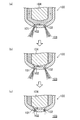
この点、図1を参照しながら具体的に説明する。図1は、この種のインジェクタでの、燃焼室に露出した先端部を例示したものである。図示のインジェクタ100の先端部の内部には、加圧された燃料が流入する空間(サック部101と称する)が形成されており、そのサック部101が、複数の噴射孔102を介して燃焼室103と連通している。
This point will be specifically described with reference to FIG. FIG. 1 exemplifies a tip portion exposed to a combustion chamber in this type of injector. A space (referred to as a sac portion 101) into which pressurized fuel flows is formed inside the tip portion of the illustrated
インジェクタ100の内部には、サック部101へ燃料を流入させない閉じ位置と、サック部101へ燃料を流入させる開き位置と、にスライド変位可能なニードル104が配置されていて、ミリ秒レベルの高速でニードル104が変位制御されるようになっている。
Inside the
図1の(a)に示すように、燃焼の噴射時には、ニードル104は開き位置に保持され、加圧された燃料がサック部101に流入するため、その燃料が噴射孔102を通じて燃焼室103に噴射される。そして、図1の(b)に示すように、燃料の噴射が終了し、ニードル104が変位して閉じ位置に達すると、サック部101への燃料の流入は止まるが、サック部101の燃料は、慣性力によって引き続き燃焼室103に噴射される。
As shown in FIG. 1 (a), during combustion injection, the
そうして、サック部101から燃料が流出すると、図1の(c)に示すように、サック部101が負圧になるため、燃焼室103からサック部101に逆流する流れが形成される。その結果、噴射孔102やその周辺にデポジットが形成されてしまい、デポジットによって燃料の流れが妨げられる結果、燃料の噴射量や噴射状態が適切に行われなくなるおそれがある。
When the fuel flows out from the
このような問題に対し、特許文献1には、サック部への逆流を抑制する様々な方法が提案されている。 With respect to such a problem, Patent Literature 1 proposes various methods for suppressing the backflow to the sack portion.
具体的には、燃料の噴射終了後に、サック部だけが燃料で満たされるようにニードルを再度リフトさせる方法(方法1)や、燃料の噴射終了時に、サック部に燃料が残留するようにニードルの閉弁速度を小さく調整する方法(方法2)、アウターニードルとインナーニードルからなる特殊なニードルを用いる方法(方法3)、噴射孔の開口の外側に開閉可能な弁を設ける方法(方法4)が提案されている。 Specifically, after the fuel injection is completed, the needle is lifted again so that only the sac portion is filled with fuel (Method 1), or at the end of the fuel injection, the needle is placed so that the fuel remains in the sac portion. A method of adjusting the valve closing speed (Method 2), a method of using a special needle composed of an outer needle and an inner needle (Method 3), and a method of providing a valve that can be opened and closed outside the opening of the injection hole (Method 4). Proposed.
インジェクタの作動機構には様々な方式があるが、特許文献1では、その中でも、ディーゼルエンジン用の、油圧でニードルを開閉させる方式(フロート式)を採用したインジェクタが対象とされている(図2)。 Although there are various types of injector operating mechanisms, Patent Document 1 specifically targets an injector that employs a method for hydraulically opening and closing a needle (float type) for a diesel engine (FIG. 2). ).
具体的には、そのインジェクタ21のニードル214は、スプリング216によって閉じ方向に付勢されており、ニードル214の基端側には、ニードル214の先端側にあるサック部220と共に、高圧の燃料が導入される制御室215が形成されている。制御室215には、導入した燃料を排出するリリーフ通路218が接続されており、そのリリーフ通路218はソレノイド弁219で開閉制御されるようになっている。 Specifically, the needle 214 of the injector 21 is biased in the closing direction by a spring 216, and high-pressure fuel is fed to the proximal end side of the needle 214 together with the sack portion 220 on the distal end side of the needle 214. A control room 215 to be introduced is formed. A relief passage 218 for discharging the introduced fuel is connected to the control chamber 215, and the relief passage 218 is controlled to be opened and closed by a solenoid valve 219.
ソレノイド弁219が閉じると、制御室215及びサック部220の燃圧が共に上昇し、ニードル214の基端側と先端側で圧力差が無くなるので、スプリング216の付勢力により、ニードル214は閉じ方向に移動する。一方、ソレノイド弁219が開くと、制御室215の燃圧が低下し、ニードル214の基端側が先端側より低圧になるので、スプリング216の付勢力に抗して、ニードル214は開き方向に移動する。 When the solenoid valve 219 is closed, the fuel pressure in the control chamber 215 and the sac portion 220 rises, and there is no pressure difference between the proximal end side and the distal end side of the needle 214. Moving. On the other hand, when the solenoid valve 219 is opened, the fuel pressure in the control chamber 215 is reduced, and the proximal end side of the needle 214 becomes lower than the distal end side, so that the needle 214 moves in the opening direction against the urging force of the spring 216. .
すなわち、引用文献1のインジェクタ21では、ソレノイド弁219の開閉によって得られる燃料の圧力差を利用して、ニードル214の動作が制御されている。 That is, in the injector 21 of the cited document 1, the operation of the needle 214 is controlled using the fuel pressure difference obtained by opening and closing the solenoid valve 219.
特許文献1の方法1は、指示された適量の燃料を噴射した後に、再度ニードルをリフトさせ、サック部だけを燃料で満たして燃焼室に燃料が漏れないように、ニードルの動作を制御しなければならない。しかし、サック部の容量は僅かであるうえに、超高速かつ高精度な制御が求められる。加えて、ニードルの先端が弁座に着座して閉じられる瞬間、ニードルは若干バウンドする。そのため、現実には、そのようなニードルの制御は難しく、燃料が燃焼室に漏れて不具合を生じるおそれがある。 In Method 1 of Patent Document 1, after injecting an appropriate amount of fuel, the needle is lifted again, and the operation of the needle must be controlled so that only the sack portion is filled with fuel and fuel does not leak into the combustion chamber. I must. However, the capacity of the sack portion is small, and ultra-high speed and high-precision control is required. In addition, the needle bounces slightly when the tip of the needle is seated and closed. Therefore, in reality, it is difficult to control such a needle, and fuel may leak into the combustion chamber and cause a problem.
方法2についても、ニードルの閉弁速度を小さく調整するためには、スプリングの付勢力を特定の強さに減じる必要がある。そのためには、変位している最中のニードルの基端側と先端側と(双方の容積が変化している状態)で、燃圧に一定の圧力差が生じるように、ソレノイド弁の開閉を調整しなければならない。このような制御もまた、現実には難しい。
Also in the
また、方法3や方法4は、構造が複雑で、その他の不具合を生じるおそれもあり、実用化するのは容易でない。
In addition, the method 3 and the
更に、吸気行程で燃料が噴射される場合、最適な噴霧状態が得られるように、燃焼室内の流動を考慮して燃料噴射の条件が設定されているが、ニードルの開弁速度を小さくすると、噴射速度が遅くなり、適切な噴霧状態が得られずに、燃費等に影響を与えるおそれがある。 Furthermore, when fuel is injected in the intake stroke, the conditions for fuel injection are set in consideration of the flow in the combustion chamber so that an optimal spray state can be obtained, but if the valve opening speed of the needle is reduced, There is a possibility that the injection speed becomes slow and an appropriate spray state cannot be obtained, which affects fuel consumption and the like.
そこで、本発明の目的は、実用可能な容易な制御で、燃料噴射後のインジェクタ内への逆流を抑制し、吸気行程中の、燃焼室での適切な燃料噴射が、長期にわたって安定して行えるようにすることにある。 Therefore, an object of the present invention is to control the backflow into the injector after fuel injection with easy control that can be used practically, and to perform appropriate fuel injection in the combustion chamber during the intake stroke stably over a long period of time. There is in doing so.
ここで開示するのは、気筒内の燃焼室で燃料を噴射するインジェクタを備えたエンジンの制御装置である。 Disclosed herein is an engine control device including an injector that injects fuel in a combustion chamber in a cylinder.
前記インジェクタは、前記燃焼室に先端部が露出するボディと、前記先端部の内部に形成されていて燃料が流入する空間からなるサック部と、前記燃焼室と前記サック部とに連通する噴射孔と、前記ボディの内部にスライド可能に配置され、前記サック部へ燃料を流入させない閉じ位置と、前記サック部へ燃料を流入させる開き位置とに変位するニードルと、を有している。 The injector includes a body having a tip exposed in the combustion chamber, a sack formed in the tip and a space into which fuel flows, and an injection hole communicating with the combustion chamber and the sack And a needle that is slidably disposed inside the body and displaces to a closed position where fuel does not flow into the sac portion and an open position where fuel flows into the sack portion.
前記制御装置は、例えば、前記エンジンの運転状態に応じて、吸気行程中に行われる燃料の噴射を制御する燃料噴射制御部と、前記燃料噴射制御部によって設定される燃料の噴射条件に基づいて、前記ニードルの動作を制御するインジェクタ制御部と、を有している。そして、前記燃料噴射制御部によって設定される燃料の噴射期間の終了時に、前記インジェクタ制御部の制御により、前記ニードルが、前記開き位置から前記閉じ位置に所定速度で変位し、前記所定速度が、前記エンジンの運転状態に応じて変更されるようになっている。 The control device is based on, for example, a fuel injection control unit that controls fuel injection performed during an intake stroke according to an operating state of the engine, and a fuel injection condition set by the fuel injection control unit. And an injector control unit for controlling the operation of the needle. Then, at the end of the fuel injection period set by the fuel injection control unit, the needle is displaced from the open position to the closed position at a predetermined speed by the control of the injector control unit, and the predetermined speed is It is changed according to the operating state of the engine.
すなわち、この制御装置によれば、燃料の噴射期間の終了時に、ニードルの閉じる速度を、所定速度に制御できる(可変できる)ので、減速して、閉じ位置に達するニードルの変位動作を緩やかすることができ、サック部が負圧になるのを抑制してサック部に燃料が残存するようにできる。ニードルがバウンドすることも抑制できる。 That is, according to this control device, at the end of the fuel injection period, the needle closing speed can be controlled (variable) to a predetermined speed, so that the needle can be decelerated and the displacement of the needle reaching the closing position can be moderated. It is possible to suppress the negative pressure in the sac portion and allow the fuel to remain in the sac portion. The bounce of the needle can also be suppressed.
その結果、燃料噴射後のサック部への燃焼室からの逆流が抑制されて、噴射孔やその周辺にデポジットが形成され難くなり、適切な燃料噴射が長期にわたって安定して行える。ニードルを、開き位置から閉じ位置、すなわち閉弁動作の全域で所定速度にするだけであるので、複雑な演算処理が不要であり、実用化も容易である。 As a result, the backflow from the combustion chamber to the sac portion after fuel injection is suppressed, and it is difficult for deposits to be formed in the injection hole and its periphery, and appropriate fuel injection can be stably performed over a long period of time. Since the needle is only set to a predetermined speed from the open position to the closed position, that is, in the entire valve closing operation, complicated arithmetic processing is unnecessary and practical application is easy.
そして、吸気行程中の燃料噴射では、燃料の噴霧状態によっては燃費等に悪影響を与えるおそれがある。例えば、減速する閉じ制御を行った場合、燃料噴射の終了時に、燃焼室に噴射される燃料の噴射速度が遅くなって燃料の噴霧状態に悪影響を与えるおそれがある。それに対し、この制御装置では、エンジンの運転状態に応じてニードルの閉じる速度が変更されるので、閉じ制御によって燃費等に悪影響が及ぶのを抑制することができる。 In the fuel injection during the intake stroke, depending on the fuel spray state, there is a risk of adversely affecting the fuel consumption. For example, when the closing control for decelerating is performed, the injection speed of the fuel injected into the combustion chamber becomes slow at the end of the fuel injection, which may adversely affect the fuel spray state. On the other hand, in this control device, the needle closing speed is changed in accordance with the operating state of the engine, so that it is possible to suppress adverse effects on fuel consumption and the like due to the closing control.
前記インジェクタには、電流制御によって駆動するインジェクタを採用するのが好ましい。すなわち、前記インジェクタは、前記燃焼室に先端部が露出するボディと、前記先端部の内部に形成されていて燃料が流入する空間からなるサック部と、前記燃焼室と前記サック部とに連通する噴射孔と、前記ボディの内部にスライド可能に配置され、前記サック部へ燃料を流入させない閉じ位置と、前記サック部へ燃料を流入させる開き位置とに変位するニードルと、前記ニードルに前記閉じ位置に向かう推進力を与えるバネと、電流の供給により、前記ニードルに前記開き位置に向かう推進力を与える開き駆動部と、を有するものとするのが好ましい。 The injector is preferably an injector that is driven by current control. That is, the injector communicates with a body having a tip exposed in the combustion chamber, a sac formed inside the tip and including a space into which fuel flows, and the combustion chamber and the sack. An injection hole, a slidably disposed inside the body, a needle that displaces into a closed position where fuel does not flow into the sac part, and an open position where fuel flows into the sack part; and the closed position on the needle It is preferable to have a spring that applies a driving force toward the opening and an opening drive unit that applies a driving force toward the opening position to the needle by supplying a current.
そうして、前記制御装置は、例えば、前記エンジンの運転状態に応じて、吸気行程中に行われる燃料の噴射を制御する燃料噴射制御部と、前記燃料噴射制御部によって設定される燃料の噴射条件に基づいて、前記開き駆動部へ供給する電流を制御するインジェクタ制御部と、を有するものとし、前記燃料噴射制御部によって設定される燃料の噴射期間の終了時に、前記ニードルが、前記エンジンの運転状態に応じた所定速度で前記開き位置から前記閉じ位置に変位するように、前記インジェクタ制御部が、電流値を変更しながら前記開き駆動部に減速電流を供給するようにするとよい。 Thus, the control device, for example, in accordance with the operating state of the engine, a fuel injection control unit that controls fuel injection performed during the intake stroke, and fuel injection set by the fuel injection control unit An injector control unit that controls a current supplied to the opening drive unit based on a condition, and at the end of a fuel injection period set by the fuel injection control unit, the needle is connected to the engine. The injector control unit may supply a deceleration current to the opening driving unit while changing a current value so that the opening control unit is displaced from the opening position to the closing position at a predetermined speed according to an operation state.
そうすれば、ミリ秒レベルの超高速な制御であっても、レスポンスよくインジェクタを作動させることができ、高精度な制御が安定して行える。 By doing so, the injector can be operated with good response even with ultra-high speed control at the millisecond level, and high-precision control can be stably performed.
その場合、前記減速電流は、前記噴射期間の開始時に前記開き駆動部に供給される開き変位電流よりも小さく設定するのが好ましい。 In that case, it is preferable that the deceleration current is set smaller than an opening displacement current supplied to the opening driving unit at the start of the injection period.
そうすれば、ニードルの減速を適度に行えるうえに、供給する電流量を過不足なくできるので、効率的な制御が行える。 By doing so, the needle can be moderately decelerated and the amount of current to be supplied can be adequately and efficiently controlled.
前記エンジンの運転状態が、前記エンジンの回転数である場合には、当該回転数が低くなるほど、前記所定速度が速くなるように変更するのが好ましい。 When the operating state of the engine is the rotational speed of the engine, it is preferable that the predetermined speed is changed so as to decrease as the rotational speed decreases.
エンジン回転数が低い運転領域では、燃焼室で形成される流動が弱くなる。そのため、燃焼室に噴射される燃料の噴射速度が遅くなると、その影響を受け易い。それに対し、このような設定を行えば、減速閉じ制御による燃料の噴霧状態への悪影響を抑制することができる。 In the operating region where the engine speed is low, the flow formed in the combustion chamber is weak. Therefore, when the injection speed of the fuel injected into the combustion chamber becomes slow, it is easily affected. On the other hand, if such a setting is performed, it is possible to suppress an adverse effect on the fuel spray state by the deceleration closing control.
開示するエンジンの制御装置によれば、燃料噴射後のインジェクタ内への逆流を抑制することが実用化できる。その結果、燃焼室での燃料噴射が長期にわたって安定して行えるようになる。 According to the disclosed engine control apparatus, it is practical to suppress the backflow into the injector after fuel injection. As a result, fuel injection in the combustion chamber can be stably performed over a long period of time.
以下、本発明の実施形態を図面に基づいて詳細に説明する。ただし、以下の説明は、本質的に例示に過ぎず、本発明、その適用物あるいはその用途を制限するものではない。 Hereinafter, embodiments of the present invention will be described in detail with reference to the drawings. However, the following description is merely illustrative in nature and does not limit the present invention, its application, or its use.
<エンジン>
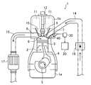
図2に、本実施形態で開示するエンジン1を示す。このエンジン1は、動力源として自動車に搭載される多気筒ガソリンエンジンである。ガソリンエンジンではあっても、このエンジン1の燃料は、ガソリンを主成分とするものであればよい(例えば、ガソリンにエチルアルコール等を含有させたものでもよい)。
<Engine>
FIG. 2 shows an engine 1 disclosed in the present embodiment. The engine 1 is a multi-cylinder gasoline engine mounted on a car as a power source. Even if it is a gasoline engine, the fuel of this engine 1 should just have gasoline as a main component (for example, what made ethyl alcohol etc. contain in gasoline) may be sufficient.
このエンジン1では、シリンダブロック1aと、その上部に組み付けられたシリンダヘッド1bとで、その主体が構成されている。シリンダブロック1aには、複数の円筒状の気筒2(図2では、その1つを示す)が紙面に直交して並ぶように設けられている。各気筒2には、ピストン3が往復動可能に挿入されていて、これらピストン3は、コネクティングロッド4を介してクランクシャフト5と連結されている。
In the engine 1, a
これらピストン3の往復動作に応じてクランクシャフト5が回転する。クランクシャフト5の回転動力は、変速機(図示せず)を介して出力されるようになっている。変速機は、ギヤ段(例えば1速〜6速)の変更が可能な機構を有しており、設定されたギヤ段で、回転動力が車輪に伝達されるようになっている。変速機は、自動変速機(いわゆるAT)や手動変速機(いわゆるMT)でもよく、このエンジン1では、その種類は問わない。
The
各気筒2の内部上方には、シリンダヘッド1bの下面とピストン3の上面とで上下が仕切られた燃焼室6が形成されている。図示しないが、ピストン3の上面には、燃焼室6に噴射された燃料の流動を誘導するキャビティ(凹部)が形成されている。燃焼室6の上部には、シリンダヘッド1bに形成された吸気ポート7の吸気口及び排気ポート8の排気口が開口している。これら吸気口及び排気口を開閉する吸気弁9及び排気弁10が、シリンダヘッド1bにそれぞれ設けられている。なお、吸気弁9及び排気弁10の個数は問わないが、このエンジン1では、各気筒2に、吸気弁9及び排気弁10が、それぞれ2つずつ設けられている。
A
吸気弁9及び排気弁10の各々は、シリンダヘッド1bに設置された動弁機構11により、クランクシャフト5の回転に連動して開閉駆動される。動弁機構11には、弁のリフト量や開閉タイミングが固定されたものや可変できるものなど、様々な機構があり、使用するエンジンの制御に応じて適宜選択される。
Each of the
シリンダヘッド1bには、点火プラグ12及びインジェクタ40が、各気筒2に設けられている。点火プラグ12は、その先端部に火花を発生する放電端子を有しており、その先端部が燃焼室6の上部中央(上下方向から見た中央)に突出するように、シリンダヘッド1bに配置されている。
A
インジェクタ40は、燃料を噴射する軸形状をした部材である。エンジン1の運転時には、図外の燃料供給経路を通じて、燃料が所定の燃圧でインジェクタ40に供給されるようになっている。インジェクタ40は、その先端部が吸気側から燃焼室6の上部側方(上下方向から見た側方)に露出するように、斜め下向きに延びた状態でシリンダヘッド1bに配置されている。すなわち、このインジェクタ40は、燃焼室6で燃料を噴射する、いわゆる直噴型のインジェクタである(インジェクタ40の構造の詳細については後述)。
The
シリンダヘッド1bの一方の側面に開口する吸気ポート7の導入口には、吸気通路14が接続されている。これら吸気通路14及び吸気ポート7を通じて、外気(新気)が燃焼室6に供給される。また、シリンダヘッド1bの他方の側面に開口する排気ポート8の導出口には、排気通路15が接続されている。これら排気ポート8及び排気通路15を通じて、燃焼室6で生成された排ガス(燃焼ガス)が排出される。
An
吸気通路14には、アクセルの開度(運転者がアクセルペダルを踏み込み操作することによって変化)に応じて外気の流量を調整する電子制御式のスロットル弁16が設けられている。スロットル弁16は、アクセルペダルの開度から独立して開閉制御することも可能である。
The
排気通路15には、触媒コンバータ17が設けられている。触媒コンバータ17には、三元触媒が内蔵されており、排ガスが触媒コンバータ17を通過することで、排ガス中の有害成分(NOx,CO,HC)が浄化されるようになっている。
A
<制御装置>
エンジン1の運転は、主に、PCM(パワートレインコントロールモジュール)20によって総合的に制御されている。例えば、PCM20には、エンジン1の運転状態を検出するために、各種センサ類から様々な情報が絶えず入力されるようになっており、PCM20は、これら情報に基づいて、動弁機構11や点火プラグ12、スロットル弁16、インジェクタ40等がエンジン1の運転状態に応じて適切に作動するように制御する。
<Control device>
The operation of the engine 1 is mainly controlled by a PCM (powertrain control module) 20 mainly. For example, in order to detect the operating state of the engine 1, various information is constantly input from the various sensors to the
図3に、インジェクタ40の制御に関連したブロック図を示す。PCM20には、エンジン回転数センサ21、ギヤ段検出センサ22、車速センサ23、アクセル開度センサ24などが電気的に接続されている。エンジン回転数センサ21は、エンジン1の回転数を検出し、ギヤ段検出センサ22は、変速機のギヤ段を検出する。車速センサ23は、自動車の車速を検出し、アクセル開度センサ24は、アクセルの開度を検出する。エンジン1の運転時には、これらセンサから、常時、PCM20に情報が入力されるようになっている。
FIG. 3 shows a block diagram related to the control of the
PCM20は、エンジン1の運転状態とエンジン1の出力指示に応じて目標とするトルクを設定し、設定した目標トルクをインジェクタECU30に出力する。具体的には、PCM20は、これらセンサから入力される情報に基づいて、エンジン回転数やエンジン負荷がどのような状態にあるのかを判断し、その状態とアクセルの開度とから、次に目標とするトルクを設定し、インジェクタECU30に出力する。
The
インジェクタECU30は、インジェクタ40に付設された制御装置であり、インジェクタ40の制御に特化した機能を有している。インジェクタECU30は、PCM20で設定される目標トルクとエンジン1の運転状態とに基づいて、インジェクタ40の後述するニードル42の動作を制御する。具体的には、目標トルクの設定値に対応した燃料の噴射量(要求噴射量)を設定し、その要求噴射量とエンジン1の運転状態とに基づいて、インジェクタ40に所定の電流が供給されるように制御する。
The
インジェクタECU30には、制御が高速過ぎて、フィードバック制御では間に合わないために、エンジン負荷及びエンジン回転数に応じて燃料噴射のパターンが設定された、複数の制御用のマップが実装されている。インジェクタECU30は、これらマップの中からエンジン1の運転状態に応じたマップを選択し、その噴射パターンに従って燃料が噴射されるように、インジェクタ40に供給する電流を制御する。
The
このようなインジェクタECU30の設置により、燃料噴射の制御に関する演算処理が独立して行えるので、PCM20の処理負担が軽減され、燃料噴射の制御が、より高速かつ高精度に行える。
By installing the
このように、このエンジン1では、PCM20とインジェクタECU30との協働によって燃料の噴射が制御され、インジェクタECU30によってインジェクタ40の動作が制御されるように構成されている。すなわち、このエンジン1では、PCM20及びインジェクタECU30が「制御装置」に相当している。そして、PCM20及びインジェクタECU30によって「燃料噴射制御部」が構成され、インジェクタECU30によって「インジェクタ40制御部」が構成されている。ただし、インジェクタECU30は必須ではない。PCM20にインジェクタECU30と同等の機能を設け、PCM20だけで「燃料噴射制御部」を構成してもよい。
As described above, the engine 1 is configured such that fuel injection is controlled by the cooperation of the
<インジェクタ>
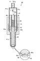
図4に、インジェクタ40の構造を具体的に示す。このインジェクタ40は、直動式の多噴孔型インジェクタであり、電気制御によって駆動するように構成されている。具体的には、インジェクタ40は、ボディ41、ニードル42、コア43、ソレノイドコイル44、コイルバネ45、コネクタ46などで構成されている。なお、本実施形態の開き駆動部は、コア43及びソレノイドコイル44によって構成されている。
<Injector>
FIG. 4 specifically shows the structure of the
ボディ41は、略円筒軸状の部材からなり、通常は複数のパーツを組み合わせて構成されている。ボディ41は、その先端部が燃焼室6に露出するように、シリンダヘッド1bに取り付けられている。ボディ41の基端部には、燃料を導入する導入口41aと、導入した燃料を収容する基端側燃料室41bとが設けられている。導入口41aと基端側燃料室41bとの間には、異物を除去するストレーナ41cが取り付けられている。ボディ41の先端部には、ボディ41の内部の中間に挿嵌されたコネクタ46を介して先端側燃料室41dが設けられている。
The
コネクタ46は、その中心に貫通した軸孔46aを有する円柱状のパーツである。軸孔46aの基端側には、円筒状のバネ止め47が固定されている。軸孔46aの先端側にはコイルバネ45が挿入されており、コイルバネ45の基端側がバネ止め47によって支持されている。
The
先端側燃料室41dには、コイルバネ45の先端側を受け止めるように、軸状のニードル42と、ニードル42の基端部に固定されたコア43とが配置されている。これらニードル42及びコア43は、インジェクタ40の中心線Aに沿って所定のリフト量でスライド可能であり、コイルバネ45によって先端側に付勢されている。
An
コア43の外周面は、ボディ41の内周面に沿って摺動するように形成されており、コア43の外周部には磁石43aが埋設されている。また、コア43の内部には、コア43で仕切られた先端側燃料室41dの基端側の部分と先端側の部分とを連通させる液流路43bが形成されている。
The outer peripheral surface of the
従って、基端側燃焼室6に導入された燃料は、軸孔46a及び液流路43bを通じて先端側燃料室41dにも導入される。エンジン1の運転時には、基端側燃料室41bに燃料が供給されるので、基端側燃焼室6及び先端側燃料室41dは、常時、所定の燃圧の燃料で満たされた状態となる。
Therefore, the fuel introduced into the proximal end
ボディ41の先端部の内部、つまり先端側燃料室41dの末端には、外方に僅かに凹む空間からなるサック部48が形成されている。サック部48の周囲には、ニードル42の先端が圧接して液封される環状の座部48aが設けられている。ボディ41の先端部には、複数の噴射孔49が形成されており、サック部48は、これら噴射孔49を介して燃焼室6と連通している。
A
ニードル42は、その先端が座部48aに圧接する位置(閉じ位置)へと向かうように、コイルバネ45によって推進力が与えられており、外部から力が作用しない限り、サック部48と先端側燃料室41dとの間は閉じられ、サック部48に燃料を流入させないようになっている。
The
ボディ41の内部に位置するコア43と対向するように、ボディ41の外部にソレノイドコイル44が設けられている。図示しないが、ソレノイドコイル44には、インジェクタECU30の指示に従って、所定のタイミングで所定量の電流が供給されるようになっている。ソレノイドコイル44に電流が供給されることで、磁界が形成されてコア43の磁石43aに磁力が作用する。それにより、コア43に、コイルバネ45の弾性力に抗して基端側にスライドさせる推進力が与えられ、ニードル42は、その先端が座部48aから離れてリフトし、サック部48に燃料を流入させる位置(開き位置、図4の拡大図に仮想線で示す)へと向かうようになっている。
A
すなわち、このインジェクタ40の場合、ソレノイドコイル44へ所定の電流(開き変位電流)を供給することで、磁力の作用で、ニードル42が開き位置に変位し、サック部48へ燃料が流入して燃料噴射が開始する。そうして、ソレノイドコイル44へ所定の電流(開き保持電流)を供給することで、ニードル42が開き位置に保持され、燃料噴射が継続される。そして、ソレノイドコイル44への電流の供給が停止されることで、コイルバネ45の弾性力の作用で、ニードル42が閉じ位置に変位し、サック部48への燃料の流入が停止して燃料噴射が終了する。
That is, in the case of this
従って、このインジェクタ40であれば、燃料噴射の開始時には、ソレノイドコイル44への電流の供給により、直ちに開弁動作が行え、燃料噴射の終了時には、ソレノイドコイル44への電流の供給の停止により、直ちに閉弁動作が行える。そのため、燃料の圧力差を利用したフロート式のインジェクタと異なり、タイムラグがほとんど無しに制御できるので、ミリ秒を超えるような高速であっても、高精度な制御が安定して行える。
Therefore, with this
また、一般に、ニードル42がリフトする際、ニードル42に作用する力Fは、次の式(1)で表現できる。
In general, when the
(1)F=k・x+ΔP・S−Mag
ここで、kはコイルバネ45のバネ定数、xはリフト量、ΔPは閉じ位置に向かってコア43に作用する燃圧差、Sはその燃圧差が作用するコア43の面積、Magはソレノイドコイル44によって発生する磁力、を表している。
(1) F = k · x + ΔP · S-Mag
Here, k is the spring constant of the
引用文献1のような、ディーゼル用のフロート式のインジェクタと比べると、このガソリン用の直動式のインジェクタ40は、圧縮行程でなく吸気行程で噴射されるので、k・xやΔP・Sは小さくなる。そのため、このインジェクタ40によれば、比較的小さい電流で制御できるので、バッテリーの電力消費も抑制できる。
Compared to the float type injector for diesel as in the cited document 1, the direct
<燃料噴射の制御>
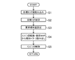
次に、図5のフローチャートを参照しながら、燃料噴射の制御について具体的に説明する。PCM20は、図3に示したように、自動車の運転中は常時、各種センサが検出する値を読み込んでエンジン1の運転状態を判断しており(ステップS1)、要求されるエンジン1の運転状態となるように、燃焼サイクルごとに目標トルクを設定し(ステップS2)、インジェクタECU30に、エンジン回転数やエンジン負荷の情報とともに、その設定した目標トルクを出力する。
<Control of fuel injection>
Next, the fuel injection control will be specifically described with reference to the flowchart of FIG. As shown in FIG. 3, the
インジェクタECU30は、PCM20から目標トルク等の情報が入力されると、それに応じた要求噴射量を設定する(ステップS3)。インジェクタECU30は、エンジン1の運転状態、すなわち、その時のエンジン回転数及びエンジン負荷に応じたマップを選択してその噴射パターンを読み出す(ステップS4)。そうして、インジェクタECU30は、その噴射パターンで要求噴射量が噴射されるように、インジェクタ40を電流制御する(ステップS5)。
When the information such as the target torque is input from the
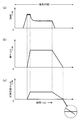
図6に、通常の場合での、噴射パターンの一例を模式的に示す。(a)は、ソレノイドコイル44に供給される電流の変化を、(b)は、ニードル42のリフト量の変化を、(c)は、サック部48の差圧(サック部48の内圧−燃焼室6の内圧)の変化を、それぞれ表している。
FIG. 6 schematically shows an example of an injection pattern in a normal case. (A) shows the change in the current supplied to the
横軸は時間(msのレベル)を表している。このエンジン1では、吸気行程中に燃料が噴射される。噴射パターンによっては、複数回に分けて噴射される場合もあるが、ここでは1回で噴射される場合を表している。 The horizontal axis represents time (ms level). In the engine 1, fuel is injected during the intake stroke. Depending on the injection pattern, the injection may be performed in a plurality of times, but here, the case where the injection is performed once is shown.
リフト量が「0」の位置が閉じ位置に相当し、リフト量が最大の位置が開き位置に相当する。ニードル42が閉じ位置から離れて、再度閉じ位置に戻るまでの期間が、PCM20及びインジェクタECU30によって設定される燃料の噴射期間(理論的にインジェクタ40から燃焼室6に燃料が噴射される状態にある期間)である。従って、(b)において台形の面積で表される部分が要求噴射量に対応する。
The position where the lift amount is “0” corresponds to the closed position, and the position where the lift amount is maximum corresponds to the open position. The period until the
このインジェクタ40では、上述したように、燃料噴射の開始時には電流制御によって開弁動作が行われるので、ニードル42を高速で変位させることができ、噴射パターンに対して僅かなタイムラグでニードル42のリフトを追随させることができる。すなわち、高精度な開弁動作が行える。開弁動作では、コイルバネ45や燃圧に抗してニードル42を高速でリフトさせる必要があるため、インジェクタECU30は、ソレノイドコイル44に比較的大きな電流(開き変位電流)を供給する。
In this
そして、開き位置に達すると、インジェクタECU30は、ソレノイドコイル44に開き変位電流よりも小さい電流(開き保持電流)を供給する。それにより、ニードル42は開き位置に保される。
When reaching the open position, the
そして、所定期間が経過すると、インジェクタECU30は、ソレノイドコイル44への開き保持電流の供給を停止し、閉弁動作が開始される。このとき、電流制御により直ちにコイルバネ45による閉弁動作が行える。なお、閉弁動作ではコイルバネ45の弾性力によってニードル42が変位するため、開弁動作よりもニードル42の変位速度は小さくなっている(傾きが緩やか)。
When the predetermined period has elapsed, the
そうして、ニードル42が閉じ位置に達することで噴射期間が終了し、燃料の噴射が停止する。ところが、このとき、(c)に拡大して示すように、サック部48への燃料の流入は止まるが、サック部48の燃料は、慣性力によって引き続き、燃焼室6に噴射されるため、サック部48が負圧になる。
Then, when the
特に、吸気行程は、圧縮行程と異なり、燃焼室6の内圧が低くいため、燃料が流出し易くなっており、よりいっそう負圧になり易い。
In particular, in the intake stroke, unlike the compression stroke, the internal pressure of the
それにより、噴射期間の終了後(ニードル42が閉じ位置に達した後)に、直前の排気行程で燃焼室6に残留した既燃ガス(カーボン等を含んでいる)がサック部48に逆流し、噴射孔49やその周辺に、デポジットが形成されるおそれがある。
Thereby, after the injection period ends (after the
(減速閉じ制御)
そこで、このエンジン1では、燃料噴射の終了後に発生し得るサック部48の負圧化が抑制できるように工夫されている。すなわち、レスポンスに優れたインジェクタ40を活用し、噴射期間の終了時に、ニードル42が開き位置から閉じ位置に変位する速度を減少させるようにした。
(Deceleration closing control)
In view of this, the engine 1 is devised so that negative pressure of the
具体的には、開き保持電流の供給が停止して閉弁動作が開始すると、本来であれば、ニードル42は、コイルバネの弾性による推進力により、一定の速度で閉じ位置に向かって変位する。それに対し、このエンジンでは、インジェクタECU30により、ニードル42の速度を減速させる減速電流が、ソレノイドコイル44に供給されるようになっている。
Specifically, when the supply of the open holding current is stopped and the valve closing operation is started, the
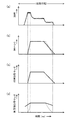
図7に、減速閉じ制御を行った場合での噴射パターンを例示する。(a)は、ソレノイドコイル44に供給される電流の変化を、(b)は、ニードル42のリフト量の変化を、(c)は、サック部48の差圧の変化を、(d)は、サック部48の燃料量の変化を、それぞれ表している。
FIG. 7 illustrates an injection pattern when the deceleration closing control is performed. (A) shows the change in the current supplied to the
(a)に示すように、通常の噴射期間が終了して、開き保持電流の供給が停止されると、減速電流がソレノイドコイル44に供給される。減速電流は、コイルバネの推進力に抗してニードル42の速度を所定の値まで減速させればよいため、開き変位電流よりも小さい電流である。減速電流は、減速量に応じてその大きさが調整される。
As shown in (a), when the normal injection period ends and the supply of the open holding current is stopped, the deceleration current is supplied to the
減速電流の大きさを調整することで、所望する大きさで、コイルバネの推進力に抗する逆向きの推進力をニードルに与えることができるので、ニードルの変位速度を自在に調整することができる。電流制御であるため、高精度な制御が行える。 By adjusting the magnitude of the deceleration current, it is possible to give the needle a reverse driving force against the driving force of the coil spring at a desired size, so that the displacement speed of the needle can be freely adjusted. . Since it is current control, highly accurate control can be performed.
インジェクタECU30は、要求噴射量が一定となるように、減速された変位速度に合わせて、開き保持電流を停止するタイミングを調整する。電気制御であるため、そのような調整が可能であり、変位速度を可変させても要求噴射量を精度高く維持できる。
The
更に、減速電流は、一定の値とするのが好ましい。微小空間からなるサック部48を対象とした高速下での制御であるため、閉弁期間中に減速電流を可変すると、制御が複雑になって処理負担が増加する。ニードルの動作も安定するため、より高精度な制御が行える。
Furthermore, the deceleration current is preferably a constant value. Since the control is performed at a high speed for the
そうすることで、(b)に示すように、仮想線で示す、コイルバネのみの推進力による変位速度に比べて、減速された一定の変位速度でニードルは変位する。その結果、弁座に着座するニードル42の変位動作が緩やかになり、(c)や(d)に示すように、サック部48に燃料が残存して、サック部48が負圧になるのが抑制される。ニードル42がバウンドすることも抑制される。
By doing so, as shown in (b), the needle is displaced at a constant decelerating speed that is decelerated compared to the displacement speed due to the propulsive force of only the coil spring, which is indicated by a virtual line. As a result, the displacement operation of the
その結果、燃料噴射後のサック部48への燃焼室6からの逆流が抑制されて、噴射孔49やその周辺にデポジットが形成され難くなるので、適切な燃料噴射が長期にわたって安定して行える。ニードル42を減速させるだけであるので、複雑な演算処理が不要であり、インジェクタECU30の処理負担も軽減できる。
As a result, the backflow from the
(エンジンの運転状態の影響)
このような減速閉じ制御を行った場合、燃料噴射の終了時に、燃焼室6に噴射される燃料の噴射速度が遅くなるおそれがある。
(Effect of engine operating conditions)
When such deceleration closing control is performed, the injection speed of fuel injected into the
吸気行程で燃料を噴射する場合、燃焼状態を制御するために、噴射のタイミングや、ピストン3のキャビティの形状等との組み合わせにより、タンブル流やスワール流等、所定の流動が燃焼室6で形成されて、最適な噴霧状態が得られるように、燃料噴射の条件が設定されている。それに対し、燃料の噴射速度が遅くなると、最適な噴霧状態が得られずに、燃費等に影響を与えるおそれがある。
When fuel is injected in the intake stroke, a predetermined flow such as a tumble flow or a swirl flow is formed in the
特に、エンジン回転数が低い運転領域では、エンジン回転数が高い運転領域に比べて、燃焼室6で形成される流動が弱いため、その影響を受け易い。そこで、このエンジン1では、エンジン回転数が低くなるほど、ニードル42の変位速度が速くなるように設定されている。
In particular, in the operation region where the engine speed is low, the flow formed in the
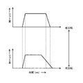
具体的には、図8に示すように、エンジン回転数が高い運転領域では、ニードル42の変位速度が相対的に遅くなるように(傾きが緩やか)、ソレノイドコイル44に供給する減速電流の値を大きく設定する。そして、エンジン回転数が低い運転領域では、ニードル42の変位速度が相対的に速くなるように(傾きが急)、ソレノイドコイル44に供給する減速電流の値を小さく設定する。
Specifically, as shown in FIG. 8, in the operating region where the engine speed is high, the value of the deceleration current supplied to the
そうすることで、減速閉じ制御による燃料の噴霧状態への悪影響を抑制することができるようになる。 By doing so, it becomes possible to suppress an adverse effect on the fuel spray state caused by the deceleration closing control.
同様に、エンジン温度の影響も受け得る。すなわち、エンジン温度が低いと、燃焼室6で噴霧された燃料が気化し難いため、燃料の噴射速度が遅くなると、最適な噴霧状態が得られずに、燃費等に影響を与えるおそれがある。
Similarly, it can be affected by engine temperature. That is, when the engine temperature is low, the fuel sprayed in the
そのため、エンジン回転数と共に、エンジン温度が低くなるほど、ニードル42の変位速度が相対的に速くなるように設定するのが好ましい。例えば、冷間始動後に、エンジン温度が所定の温度に達する、いわゆる暖気運転の完了の前後で、ニードル42の変位速度の大きさが切り替わるように設定することなどが考えられる。
Therefore, it is preferable to set so that the displacement speed of the
なお、本発明にかかるエンジンの制御装置は、上述した実施形態に限定されず、それ以外の種々の構成をも包含する。 The engine control apparatus according to the present invention is not limited to the above-described embodiment, and includes various other configurations.
例えば、燃料噴射が複数回に分けて行われる分割噴射の場合は、最後の燃料噴射の時にのみ、減速閉じ制御を行うのが好ましい。 For example, in the case of split injection in which fuel injection is performed in a plurality of times, it is preferable to perform deceleration closing control only at the time of the last fuel injection.
ニードル42の変位速度を減速するだけでなく、加速させてもよい。電流制御であれば容易に行える。
In addition to decelerating the displacement speed of the
1 エンジン
2 気筒
3 ピストン
6 燃焼室
12 点火プラグ
20 PCM(制御装置)
30 インジェクタECU(制御装置)
40 インジェクタ
41 ボディ
42 ニードル
48 サック部
49 噴射孔
1
30 Injector ECU (control device)
40
Claims (5)
前記インジェクタは、
前記燃焼室に先端部が露出するボディと、
前記先端部の内部に形成されていて燃料が流入する空間からなるサック部と、
前記燃焼室と前記サック部とに連通する噴射孔と、
前記ボディの内部にスライド可能に配置され、前記サック部へ燃料を流入させない閉じ位置と、前記サック部へ燃料を流入させる開き位置とに変位するニードルと、
を有し、
前記制御装置は、
前記エンジンの運転状態に応じて、吸気行程中に行われる燃料の噴射を制御する燃料噴射制御部と、
前記燃料噴射制御部によって設定される燃料の噴射条件に基づいて、前記ニードルの動作を制御するインジェクタ制御部と、
を有し、
前記燃料噴射制御部によって設定される燃料の噴射期間の終了時に、前記インジェクタ制御部の制御により、前記ニードルが、前記開き位置から前記閉じ位置に所定速度で変位し、
前記所定速度が、前記エンジンの運転状態に応じて変更されるように構成されており、
前記エンジンの運転状態は前記エンジンの回転数であり、当該回転数が低くなるほど、前記所定速度が速くなるように変更されることを特徴とするエンジンの制御装置。 An engine control device including an injector for injecting fuel in a combustion chamber in a cylinder,
The injector is
A body whose tip is exposed in the combustion chamber;
A sac part formed of a space into which fuel flows and is formed inside the tip part;
An injection hole communicating with the combustion chamber and the sac portion;
A needle that is slidably disposed inside the body and is displaced to a closed position where fuel does not flow into the sac part and an open position where fuel flows into the sack part;
Have
The control device includes:
A fuel injection control unit that controls fuel injection performed during an intake stroke according to an operating state of the engine;
An injector control unit that controls the operation of the needle based on a fuel injection condition set by the fuel injection control unit;
Have
At the end of the fuel injection period set by the fuel injection control unit, the needle is displaced from the open position to the closed position at a predetermined speed by the control of the injector control unit,
The predetermined speed is configured to be changed according to an operating state of the engine ,
The engine operating state is the rotational speed of the engine, and the engine speed is changed so that the predetermined speed increases as the rotational speed decreases .
前記インジェクタは、
前記燃焼室に先端部が露出するボディと、
前記先端部の内部に形成されていて燃料が流入する空間からなるサック部と、
前記燃焼室と前記サック部とに連通する噴射孔と、
前記ボディの内部にスライド可能に配置され、前記サック部へ燃料を流入させない閉じ位置と、前記サック部へ燃料を流入させる開き位置とに変位するニードルと、
前記ニードルに前記閉じ位置に向かう推進力を与えるバネと、
電流の供給により、前記ニードルに前記開き位置に向かう推進力を与える開き駆動部と、
を有し、
前記制御装置は、
前記エンジンの運転状態に応じて、吸気行程中に行われる燃料の噴射を制御する燃料噴射制御部と、
前記燃料噴射制御部によって設定される燃料の噴射条件に基づいて、前記開き駆動部へ供給する電流を制御するインジェクタ制御部と、
を有し、
前記燃料噴射制御部によって設定される燃料の噴射期間の終了時に、前記ニードルが、前記エンジンの運転状態に応じた所定速度で前記開き位置から前記閉じ位置に変位するように、前記インジェクタ制御部が、電流値を変更しながら前記開き駆動部に減速電流を供給するように構成されており、
前記エンジンの運転状態は前記エンジンの回転数であり、当該回転数が低くなるほど、前記所定速度が速くなるように変更されることを特徴とするエンジンの制御装置。 An engine control device including an injector that injects fuel in a combustion chamber in a cylinder by current control,
The injector is
A body whose tip is exposed in the combustion chamber;
A sac part formed of a space into which fuel flows and is formed inside the tip part;
An injection hole communicating with the combustion chamber and the sac portion;
A needle that is slidably disposed inside the body and is displaced to a closed position where fuel does not flow into the sac part and an open position where fuel flows into the sack part;
A spring for applying a propulsive force to the needle toward the closed position;
An opening drive unit for supplying a propulsive force toward the opening position to the needle by supplying a current;
Have
The control device includes:
A fuel injection control unit that controls fuel injection performed during an intake stroke according to an operating state of the engine;
An injector control unit for controlling a current supplied to the opening drive unit based on a fuel injection condition set by the fuel injection control unit;
Have
The injector controller is configured to displace the needle from the open position to the closed position at a predetermined speed according to the operating state of the engine at the end of the fuel injection period set by the fuel injection controller. , Configured to supply a deceleration current to the opening drive unit while changing the current value ,
The engine operating state is the rotational speed of the engine, and the engine speed is changed so that the predetermined speed increases as the rotational speed decreases .
前記減速電流は、前記噴射期間の開始時に前記開き駆動部に供給される開き変位電流よりも小さく設定されていることを特徴とするエンジンの制御装置。 The engine control device according to claim 2,
The engine control apparatus according to claim 1, wherein the deceleration current is set to be smaller than an opening displacement current supplied to the opening drive unit at the start of the injection period.
前記インジェクタは、
前記燃焼室に先端部が露出するボディと、
前記先端部の内部に形成されていて燃料が流入する空間からなるサック部と、
前記燃焼室と前記サック部とに連通する噴射孔と、
前記ボディの内部にスライド可能に配置され、前記サック部へ燃料を流入させない閉じ位置と、前記サック部へ燃料を流入させる開き位置とに変位するニードルと、
を有し、
前記制御装置は、燃料の噴射期間の終了時に、前記ニードルを前記開き位置から前記閉じ位置に所定速度で変位させ、前記所定速度をエンジンの運転状態に応じて変更するように構成されており、
前記エンジンの運転状態は前記エンジンの回転数であり、当該回転数が低くなるほど、前記所定速度が速くなるように変更されることを特徴とするエンジンの制御装置。 An engine control device including an injector for injecting fuel in a combustion chamber in a cylinder,
The injector is
A body whose tip is exposed in the combustion chamber;
A sac part formed of a space into which fuel flows and is formed inside the tip part;
An injection hole communicating with the combustion chamber and the sac portion;
A needle that is slidably disposed inside the body and is displaced to a closed position where fuel does not flow into the sac part and an open position where fuel flows into the sack part;
Have
The control device is configured to displace the needle from the open position to the closed position at a predetermined speed at the end of the fuel injection period, and to change the predetermined speed in accordance with the operating state of the engine ,
The engine operating state is the rotational speed of the engine, and the engine speed is changed so that the predetermined speed increases as the rotational speed decreases .
前記インジェクタは、
前記燃焼室に先端部が露出するボディと、
前記先端部の内部に形成されていて燃料が流入する空間からなるサック部と、
前記燃焼室と前記サック部とに連通する噴射孔と、
前記ボディの内部にスライド可能に配置され、前記サック部へ燃料を流入させない閉じ位置と、前記サック部へ燃料を流入させる開き位置とに変位するニードルと、
前記ニードルに前記閉じ位置に向かう推進力を与えるバネと、
電流の供給により、前記ニードルに前記開き位置に向かう推進力を与える開き駆動部と、
を有し、
前記制御装置は、燃料の噴射期間の終了時に、前記ニードルが、エンジンの運転状態に応じた所定速度で前記開き位置から前記閉じ位置に変位するように、電流値を変更しながら前記開き駆動部に減速電流を供給するように構成されており、
前記エンジンの運転状態は前記エンジンの回転数であり、当該回転数が低くなるほど、前記所定速度が速くなるように変更されることを特徴とするエンジンの制御装置。 An engine control device including an injector that injects fuel in a combustion chamber in a cylinder by current control,
The injector is
A body whose tip is exposed in the combustion chamber;
A sac part formed of a space into which fuel flows and is formed inside the tip part;
An injection hole communicating with the combustion chamber and the sac portion;
A needle that is slidably disposed inside the body and is displaced to a closed position where fuel does not flow into the sac part and an open position where fuel flows into the sack part;
A spring for applying a propulsive force to the needle toward the closed position;
An opening drive unit for supplying a propulsive force toward the opening position to the needle by supplying a current;
Have
The control device is configured to change the current value so that the needle is displaced from the open position to the closed position at a predetermined speed according to an operating state of the engine at the end of the fuel injection period. Is configured to supply a deceleration current to
The engine operating state is the rotational speed of the engine, and the engine speed is changed so that the predetermined speed increases as the rotational speed decreases .
Priority Applications (5)
| Application Number | Priority Date | Filing Date | Title |
|---|---|---|---|
| JP2017040950A JP6428811B2 (en) | 2017-03-03 | 2017-03-03 | Engine control device |
| CN201880014479.0A CN110382857A (en) | 2017-03-03 | 2018-01-29 | The control device of engine |
| EP18761973.9A EP3575590B1 (en) | 2017-03-03 | 2018-01-29 | Engine control device |
| PCT/JP2018/002777 WO2018159184A1 (en) | 2017-03-03 | 2018-01-29 | Engine control device |
| US16/489,424 US11168628B2 (en) | 2017-03-03 | 2018-01-29 | Engine control device |
Applications Claiming Priority (1)
| Application Number | Priority Date | Filing Date | Title |
|---|---|---|---|
| JP2017040950A JP6428811B2 (en) | 2017-03-03 | 2017-03-03 | Engine control device |
Publications (2)
| Publication Number | Publication Date |
|---|---|
| JP2018145857A JP2018145857A (en) | 2018-09-20 |
| JP6428811B2 true JP6428811B2 (en) | 2018-11-28 |
Family
ID=63589910
Family Applications (1)
| Application Number | Title | Priority Date | Filing Date |
|---|---|---|---|
| JP2017040950A Expired - Fee Related JP6428811B2 (en) | 2017-03-03 | 2017-03-03 | Engine control device |
Country Status (1)
| Country | Link |
|---|---|
| JP (1) | JP6428811B2 (en) |
Family Cites Families (2)
| Publication number | Priority date | Publication date | Assignee | Title |
|---|---|---|---|---|
| JP2005307758A (en) * | 2004-04-16 | 2005-11-04 | Toyota Motor Corp | Fuel injection device for internal combustion engine |
| JP5478306B2 (en) * | 2010-03-18 | 2014-04-23 | 株式会社日本自動車部品総合研究所 | Fuel injection device and fuel injection valve |
-
2017
- 2017-03-03 JP JP2017040950A patent/JP6428811B2/en not_active Expired - Fee Related
Also Published As
| Publication number | Publication date |
|---|---|
| JP2018145857A (en) | 2018-09-20 |
Similar Documents
| Publication | Publication Date | Title |
|---|---|---|
| KR100404773B1 (en) | Internal combustion engine with electromagnetically driven valve | |
| JP4407731B2 (en) | Fuel injection control device | |
| JP4462315B2 (en) | Internal combustion engine control device | |
| CN103670683B (en) | For improving the stopping of turbocharged engine and the method and system of starting | |
| JP6409593B2 (en) | Water injection system for internal combustion engine | |
| CN106335492B (en) | The control device of vehicle | |
| JP5478306B2 (en) | Fuel injection device and fuel injection valve | |
| JP2010090804A (en) | Fuel injection device | |
| RU2686359C2 (en) | Multi-jet injector with sequential injection fuel | |
| CN113167185B (en) | Fuel injection control device | |
| JP3945473B2 (en) | Engine starter | |
| JP6451760B2 (en) | Engine control device | |
| JP2018145857A (en) | Control device for engine | |
| WO2018159184A1 (en) | Engine control device | |
| JPWO2013111306A1 (en) | Control device for internal combustion engine | |
| JP2017096118A (en) | Engine fuel injection control device | |
| JP2010261335A (en) | In-cylinder injection engine control device | |
| JP4075752B2 (en) | Accumulated fuel injection system | |
| JP2008267216A (en) | Fuel injection control device for internal combustion engine | |
| JP2001159360A (en) | Diesel engine fuel control system | |
| JP6327586B2 (en) | Engine fuel injection control device | |
| JP2021080864A (en) | Drive control device of fuel pump and fuel supply device | |
| JP5708479B2 (en) | Control device for hybrid vehicle | |
| JP2010121586A (en) | Fuel injection control device | |
| JP3702641B2 (en) | Engine idle operation control device |
Legal Events
| Date | Code | Title | Description |
|---|---|---|---|
| A871 | Explanation of circumstances concerning accelerated examination |
Free format text: JAPANESE INTERMEDIATE CODE: A871 Effective date: 20180620 |
|
| A975 | Report on accelerated examination |
Free format text: JAPANESE INTERMEDIATE CODE: A971005 Effective date: 20180704 |
|
| A131 | Notification of reasons for refusal |
Free format text: JAPANESE INTERMEDIATE CODE: A131 Effective date: 20180724 |
|
| A521 | Request for written amendment filed |
Free format text: JAPANESE INTERMEDIATE CODE: A523 Effective date: 20180914 |
|
| TRDD | Decision of grant or rejection written | ||
| A01 | Written decision to grant a patent or to grant a registration (utility model) |
Free format text: JAPANESE INTERMEDIATE CODE: A01 Effective date: 20181002 |
|
| A61 | First payment of annual fees (during grant procedure) |
Free format text: JAPANESE INTERMEDIATE CODE: A61 Effective date: 20181015 |
|
| R150 | Certificate of patent or registration of utility model |
Ref document number: 6428811 Country of ref document: JP Free format text: JAPANESE INTERMEDIATE CODE: R150 |
|
| LAPS | Cancellation because of no payment of annual fees |