JP6428076B2 - Tactile presentation device - Google Patents
Tactile presentation device Download PDFInfo
- Publication number
- JP6428076B2 JP6428076B2 JP2014186375A JP2014186375A JP6428076B2 JP 6428076 B2 JP6428076 B2 JP 6428076B2 JP 2014186375 A JP2014186375 A JP 2014186375A JP 2014186375 A JP2014186375 A JP 2014186375A JP 6428076 B2 JP6428076 B2 JP 6428076B2
- Authority
- JP
- Japan
- Prior art keywords
- exciter film
- diaphragm
- film
- main surface
- presentation device
- Prior art date
- Legal status (The legal status is an assumption and is not a legal conclusion. Google has not performed a legal analysis and makes no representation as to the accuracy of the status listed.)
- Active
Links
Images


Description
本発明は、ユーザに振動を伝えることで触覚フィードバックを与える触覚提示装置に関する。 The present invention relates to a haptic presentation device that provides haptic feedback by transmitting vibrations to a user.
近年、タッチパネル式のキ−ボ−ド等において、ユーザがキーをタッチした時に振動を伝えることで触覚フィードバックを与え、キーを「押した」と感じさせる触覚提示装置が提案されている。 In recent years, a touch-sensitive keyboard or the like has been proposed in which a tactile feedback is given by transmitting vibration when a user touches a key so that the key is “pressed”.
例えば、特許文献1には、圧電セラミックス等からなる圧電バイモルフ素子の両端を低弾性体で保持し、当該圧電バイモルフの中央に被振動材を接続した構造が記載されている。特許文献1の構造では、圧電バイモルフ素子に交流信号を入力して振動させることにより、接続された被振動材を介してユーザに振動を伝える。 For example, Patent Document 1 describes a structure in which both ends of a piezoelectric bimorph element made of piezoelectric ceramics or the like are held by a low elastic body, and a vibrating material is connected to the center of the piezoelectric bimorph. In the structure of Patent Document 1, vibration is transmitted to a user through a connected vibration-receiving material by inputting an AC signal to the piezoelectric bimorph element and causing it to vibrate.
図7(a)(b)に示すように、湾曲する辺方向の長さが振動板840より短い圧電体820を、振動板840の中央に貼付したユニモルフ構造体800を、指で押さえるように、力が加わった状態で撓ませる場合について説明する。
As shown in FIGS. 7A and 7B, a
この場合、図7(c)に示すように、圧電体820が貼付されている振動板840の領域は撓み振動するが、圧電体820が貼付されていない振動板840の領域が撓み振動しない。そのため、振動板840の上に配置されたキースイッチ等では「押した」感が感じられない。
In this case, as shown in FIG. 7C, the region of the
よって、振動板840より高価、且つ短い長さで十分な伸縮量のある圧電材料でも、図8(a)(b)(c)に示すように、振動板840とほぼ同じ長さの圧電体920を貼付せざるを得ず、その分、製品価格が高くなってしまう。
Therefore, even a piezoelectric material that is more expensive than the
本発明の目的は、圧電あるいは電歪による伸縮体に電界を用いて、指で振動板を押した時、振動板の全面を撓ませることで、振動板のほぼ全面で指に「押した」感を伝えられる触覚提示装置を提供することにある。 The object of the present invention is to “press” a finger on almost the entire surface of the diaphragm by bending the entire surface of the diaphragm when the diaphragm is pressed with a finger using an electric field on a piezoelectric or electrostrictive elastic body. An object is to provide a tactile sensation presentation device capable of transmitting a feeling.
この発明の触覚提示装置は、両主面に電極が形成された、圧電あるいは電歪による伸縮体と、エキサイタフィルムの端部が前記伸縮体の端部に前記伸縮体の一方主面の面方向へ接続されたエキサイタフィルムとを有する複合体と、曲げ応力が発生する状態で複合体の両端部に固定された振動板と、タッチ操作を検出するタッチ検出部と、タッチ検出部がタッチ操作を検出したときに、前記伸縮体に駆動信号を印加する駆動部と、を備えたことを特徴とする。 The tactile sense presentation device according to the present invention includes a piezoelectric or electrostrictive stretchable body having electrodes formed on both principal surfaces, and an end portion of the exciter film at the end of the stretchable body in the surface direction of one principal surface of the stretchable body. A composite having an exciter film connected to the substrate, a diaphragm fixed to both ends of the composite in a state where bending stress is generated, a touch detection unit that detects a touch operation, and the touch detection unit And a drive unit that applies a drive signal to the stretchable body when detected.
この構成では、ユーザがタッチ操作を行うと、前記伸縮体に駆動信号が印加され、前記伸縮体が面方向に伸縮する。振動板には、前記伸縮体の伸縮により、振動板の両端に力が加わり、振動板全体を撓ませようとする。 In this configuration, when the user performs a touch operation, a drive signal is applied to the stretchable body, and the stretchable body expands and contracts in the surface direction. A force is applied to both ends of the diaphragm by the expansion and contraction of the expansion and contraction, and the entire diaphragm is bent.
そのため、指で押すような力が振動板に加わった状態でも、振動板のほぼ全面で、主面に直交する方向に「押した」感を伝えることができる。 Therefore, even when a force that is pressed by a finger is applied to the diaphragm, it is possible to convey a feeling of “pressing” in a direction orthogonal to the main surface over almost the entire surface of the diaphragm.
したがって、本発明の触覚提示装置は、材料単価の高い圧電あるいは電歪伸縮体を、振動板より短い長さにすることができ、低価格化しやすい。 Therefore, the tactile sense presentation device of the present invention can make a piezoelectric or electrostrictive stretchable body having a high material unit price shorter than the diaphragm, and is easy to reduce the price.
また、前記伸縮体は、第1端部と第1端部とは逆側の第2端部とを有し、エキサイタフィルムは、第3端部と第3端部とは逆側の第4端部とを有する第1エキサイタフィルムと、第5端部と第5端部とは逆側の第6端部とを有する第2エキサイタフィルムと、で構成されている態様であってもよい。 The stretchable body includes a first end and a second end opposite to the first end, and the exciter film includes a fourth end opposite to the third end and the third end. The aspect comprised by the 1st exciter film which has an edge part, and the 2nd exciter film which has a 6th edge part on the opposite side to a 5th edge part and a 5th edge part may be sufficient.
そして、第1エキサイタフィルムの第3端部は、振動板に接続されており、第1エキサイタフィルムの第4端部の主面は、前記伸縮体の第1端部の主面に接続されており、前記伸縮体の第2端部の主面は、第2エキサイタフィルムの第5端部の主面に接続されており、第2エキサイタフィルムの第6端部は、振動板に接続されている態様であってもよい。 The third end of the first exciter film is connected to the diaphragm, and the main surface of the fourth end of the first exciter film is connected to the main surface of the first end of the stretchable body. And the main surface of the second end of the stretchable body is connected to the main surface of the fifth end of the second exciter film, and the sixth end of the second exciter film is connected to the diaphragm. It may be a mode.
また、前記伸縮体は、第1端部と第1端部とは逆側の第2端部とを有し、エキサイタフィルムは、第7端部と第7端部とは逆側の第8端部とを有する態様であってもよい。そして、前記伸縮体の第1端部は、振動板に接続されており、前記伸縮体の第2端部の主面は、エキサイタフィルムの第7端部の主面に接続されており、エキサイタフィルムの第8端部は、振動板に接続されている態様であってもよい。 The stretchable body has a first end and a second end opposite to the first end, and the exciter film is an eighth opposite to the seventh end and the seventh end. The aspect which has an edge part may be sufficient. And the 1st end part of the said expansion-contraction body is connected to the diaphragm, the main surface of the 2nd end part of the said expansion-contraction body is connected to the main surface of the 7th end part of an exciter film, Exciter The eighth end of the film may be connected to the diaphragm.
また、エキサイタフィルムの伸縮性は、前記伸縮体より伸縮性の低いことが好ましい。例えば、エキサイタフィルムの材料は、金属であることが好ましい。 Moreover, it is preferable that the elasticity of the exciter film is lower than that of the stretchable body. For example, the material of the exciter film is preferably a metal.
この構成では、エキサイタフィルムの面方向の伸縮力が、エキサイタフィルムによってあまり弱まることなく、振動板に伝わる。よって、この構成の触覚提示装置は、エキサイタフィルムの伸縮に対して振動板をより効率的に振動させることができる。 In this configuration, the stretching force in the surface direction of the exciter film is transmitted to the diaphragm without being weakened by the exciter film. Therefore, the tactile sense presentation device having this configuration can vibrate the diaphragm more efficiently with respect to expansion and contraction of the exciter film.
また、タッチ検出部は、振動板に対するタッチ操作を検出する態様であってもよいし、振動板に装着されるタッチパネルに対するタッチを検出する態様であってもよい。 Moreover, the aspect which detects the touch operation with respect to a diaphragm may be sufficient as a touch detection part, and the aspect which detects the touch with respect to the touchscreen with which a diaphragm is mounted | worn may be sufficient.
また、振動板は、エキサイタフィルムの主面に対して直交する方向に湾曲された状態で複合体の両端部に固定されることにより曲げ応力を発生させる態様でもよいし、複合体の両端部に固定されていない状態では平板面が湾曲した形状であり、湾曲した平板面が平坦になるように複合体の両端部に固定されることにより曲げ応力を発生させる態様であってもよい。 Further, the diaphragm may be configured to generate bending stress by being fixed to both ends of the composite in a state of being curved in a direction orthogonal to the main surface of the exciter film, or to both ends of the composite. In an unfixed state, the flat plate surface may have a curved shape, and a bending stress may be generated by being fixed to both ends of the composite so that the curved flat plate surface is flat.
また、前記伸縮体は、d定数が高いチタン酸ジルコン酸鉛セラミックスでも良いが、主面法線方向に電界を印加した時、主面平行方向に伸縮する電歪材料、特に高い電歪係数を持つ(フッ化ビニリデン・三フッ化エチレン・三フッ化クロロエテン)ターポリマーP(VDF/TrFE/CTFE) やフッ化ビニリデン・三フッ化エチレン共重合体P(VDF/TrFE)などが望ましい。また、伸縮量は小さいがポリフッ化ビニリデン(PVDF)といった圧電フィルムでもかまわない。 The stretchable body may be lead zirconate titanate ceramics having a high d constant. However, when an electric field is applied in the main surface normal direction, the stretch body is an electrostrictive material that expands and contracts in the parallel direction of the main surface, particularly a high electrostriction coefficient. Desirable (vinylidene fluoride / ethylene trifluoride / chloroethene trifluoride) terpolymer P (VDF / TrFE / CTFE) or vinylidene fluoride / ethylene trifluoride copolymer P (VDF / TrFE). Further, although the amount of expansion and contraction is small, a piezoelectric film such as polyvinylidene fluoride (PVDF) may be used.
この発明によれば、高価な圧電あるいは電歪材料を振動板より小さな面積で振動板のほぼ全面で「押した」感を指に使えることができ、触覚フィードバックを与える触覚提示装置の低価格化に効果がある。 According to the present invention, an expensive piezoelectric or electrostrictive material can be used on a finger with a feeling of “pushing” an almost piezoelectric piezoelectric material or electrostrictive material on almost the entire surface of the diaphragm, and the cost of the tactile presentation device that provides tactile feedback can be reduced. Is effective.
以下、本発明の第1実施形態に係る触覚提示装置10について説明する。
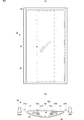
図1は、本発明の第1実施形態に係る触覚提示装置10の外観斜視図である。図2(A)は、触覚提示装置10の正面図であり、図2(B)は、触覚提示装置10の側面図である。
Hereinafter, the tactile
FIG. 1 is an external perspective view of a
触覚提示装置10は、伸縮体20、エキサイタフィルム31、エキサイタフィルム32、振動板40、およびタッチパネル50を備えている。伸縮体20は、薄板状あるいはフィルム状であり、圧電あるいは電歪によって伸縮する。エキサイタフィルム31、前記伸縮体20、及びエキサイタフィルム32は、複合体120を構成している。
The tactile
なお、エキサイタフィルム31及びエキサイタフィルム32が本発明の「エキサイタフィルム」に相当する。エキサイタフィルム31が本発明の「第1エキサイタフィルム」に相当する。エキサイタフィルム32が本発明の「第2エキサイタフィルム」に相当する。
The
触覚提示装置10は、いわゆるキーボードであり、平板状のタッチパネル50には、キー配列に対応した位置に複数のタッチセンサ80が設けられている。タッチセンサ80が本発明のタッチ検出部に相当する。
The tactile
タッチセンサ80は、ユーザのタッチ操作を検出する機能であればどの様な方式であってもよく、メンブレン式、静電容量式、圧電フィルム式、等の様々な方式を用いることができる。
The
タッチパネル50は、平板状の振動板40の一方の主面(正面)に装着されている。振動板40は、平面視して矩形状である。振動板40における短手方向の両端は、複合体120の両端部に固定されている。振動板40は、例えばアクリル樹脂PMMAで構成されている。なお、振動板40は、金属板、PET、ポリカーボネイト(PC)、PLLA、ガラス等の他の材料を用いてもよい。また、固定は振動板の長手方向両端でもよい。
The
なお、タッチパネル50は、必須ではない。例えば、振動板40の正面において、キー配列に対応した位置に複数のタッチセンサ80を設ける態様とすることも可能である。
Note that the
エキサイタフィルム31、及びエキサイタフィルム32のそれぞれは、振動板40と同様に平面視して矩形状である。
Each of the
エキサイタフィルム31、及びエキサイタフィルム32のそれぞれの伸縮性は、圧前記伸縮体20の伸縮性より低い。エキサイタフィルム31及びエキサイタフィルム32のそれぞれは、金属で構成される。
The stretchability of each of the
そのため、後述する前記伸縮体20の面方向の伸縮力が、エキサイタフィルム31及びエキサイタフィルム32によってあまり弱まることなく、振動板40に伝わる。
Therefore, the stretching force in the surface direction of the
なお、エキサイタフィルム31、及びエキサイタフィルム32のそれぞれは、ポリエチレンテレフタレート(PET)、ポリエチレンナノフタレート(PEN)、ポリエチレン(PE)、ポリプロピレン(PP)、ポリ塩化ビニル(PVC)等の他の材料を用いてもよい。
Each of the
また、エキサイタフィルム31、及びエキサイタフィルム32のそれぞれの厚みは、伸縮性を阻害しないような厚み(例えば0.02〜0.5mm程度)が望ましい。
In addition, the thickness of each of the
前記伸縮体20は、電圧が印加されることで面方向に伸縮する。ここで、前記伸縮体20は、第1端部20Aと第1端部20Aとは逆側の第2端部20Bとを有する。エキサイタフィルム31は、第3端部31Aと第3端部31Aとは逆側の第4端部31Bとを有する。エキサイタフィルム32は、第5端部32Aと第5端部32Aとは逆側の第6端部32Bとを有する。
The
そして、エキサイタフィルム31、前記伸縮体20、及びエキサイタフィルム32は、前記伸縮体20の振動板40側の主面の面方向へ各端部によって接続されている。
And the
詳述すると、エキサイタフィルム31の第3端部31Aは、振動板40に接続されている。エキサイタフィルム31の第4端部31Bの振動板40側の主面は、前記伸縮体20の第1端部20Aの振動板40とは逆側の主面に接続されている。
Specifically, the
前記伸縮体20の第2端部20Bの振動板40側の主面は、エキサイタフィルム32の第5端部32Aの振動板40とは逆側の主面に接続されている。エキサイタフィルム32の第6端部32Bは、振動板40に接続されている。
The main surface of the
図3の触覚提示装置10の部分拡大側面図に示すように、前記伸縮体20は、平面視して矩形状のベースフィルム200と、該ベースフィルム200の対向する両主面に形成された電極201Aおよび電極201Bを備える。
As shown in the partial enlarged side view of the tactile
ベースフィルム200は、電圧が印加されることで面方向に伸縮する。ベースフィルム200は、d定数が高いが高価なチタン酸ジルコン酸鉛セラミックスでも良い、主面法線方向に電界を印加した時、主面平行方向に伸縮する電歪材料、特に高い電歪係数を持つ(フッ化ビニリデン・三フッ化エチレン・三フッ化クロロエテン)ターポリマーP(VDF/TrFE/CTFE) やフッ化ビニリデン・三フッ化エチレン共重合体P(VDF/TrFE)などが望ましい。また、伸縮量は小さいがポリフッ化ビニリデン(PVDF)といった圧電フィルムでもかまわない。
The
電極201Aおよび電極201Bは、ベースフィルム200の両主面の略全面に形成されている。電極201Aおよび電極201Bは、酸化インジウムスズ(ITO)、酸化亜鉛(ZnO)、ポリチオフェンを主成分とすることが好ましい。
The electrode 201 </ b> A and the electrode 201 </ b> B are formed on substantially the entire main surfaces of the
なお、電極201Aおよび電極201Bには、銀ナノワイヤ電極を用いることも可能であるし、透光性が低くてよい使用態様であれば、アルミ蒸着電極を用いることが好ましい。
In addition, it is also possible to use a silver nanowire electrode for the
電極201Aおよび電極201Bには、図示しない引き出し用の配線導体が接続されており、駆動信号が当該配線導体を介して電極201Aおよび電極201Bへ印加されるようになっている。
A lead wiring conductor (not shown) is connected to the
ここで、エキサイタフィルム32側に配置される電極201Aは、接着層61を介してエキサイタフィルム32に装着される。エキサイタフィルム31側に配置される電極201Bは、接着層60を介してエキサイタフィルム31に装着される。
Here, the electrode 201 </ b> A disposed on the
なお、エキサイタフィルム31を金属箔とし接着層を導電性にして信号引き出し線の一部としてもかわない。
The
図4に示すように、タッチパネル50に設けられたタッチセンサ80をユーザがタッチすると、駆動部81が前記伸縮体20の電極201Aおよび電極201Bに駆動信号を印加する。これにより前記伸縮体20が伸縮する。
As shown in FIG. 4, when the user touches the
図1および図2(B)に示すように、振動板40は、複合体120の存在する側(振動板40の背面側)に対して反対側(振動板40の正面側)に湾曲して突出する形状となるように、複合体120の両端部へ固定されている。
As shown in FIGS. 1 and 2B, the
この構成により、振動板40と複合体120との間には、中空領域100が形成される。そして、この振動板40のある側が触覚提示装置10の正面側となり、複合体120がある側が触覚提示装置10の背面側となる。
With this configuration, a
ただし、本実施形態において、振動板40の湾曲状態は、説明のために誇張して記載しており、実際には、振動板40の主面と前記伸縮体20の主面は、より平行に近く、中空領域100は、できるだけ少ないほうが望ましい。
However, in the present embodiment, the curved state of the
このように、振動板40は、平板面が湾曲した状態で複合体120の両端部に固定されるため、図2(B)の白抜き矢印F901のように、曲げ応力が加わった状態で複合体120の両端部に固定される。また、複合体120は、図2(B)の白抜き矢印S901に示すように、前記伸縮体20の主面における短手方向に引張力が係った状態となる。
In this way, the
図5は、触覚提示装置10の動作説明図であり、図5(A)は、駆動信号により前記伸縮体20が縮んだタイミングでの状態を示す。図5(B)は、駆動信号が印加されていない、または駆動信号の振幅が0の状態を示す。図5(C)は、駆動信号により圧前記伸縮体20が伸びたタイミングでの状態を示す。
FIG. 5 is an operation explanatory diagram of the tactile
駆動部81が、前記伸縮体20に駆動信号を印加し、前記伸縮体20の第一方向の電界を印加すると、図5(A)の矢印S911に示すように、前記伸縮体20は、振動板40および複合体120の固定端に直交する方向(前記伸縮体20の振動板40側の主面の面方向)に沿って収縮する。
When the
ここで、前記伸縮体20は、接続フィルム31の第4端部31Bの振動板40側の主面と、接続フィルム32の第5端部32Aの振動板40とは逆側の主面とに装着されている。そのため、前記伸縮体20の収縮にともなって、複合体120は、主面に直交する方向のうち正面側にわずかに湾曲することになる。
Here, the
そして、振動板40は、複合体120に固定されている箇所(短手方向の端部)から中央方向に引っ張られる。
Then, the
これにより、振動板40は、図5(A)の矢印F911に示すように、前方へより突出するように湾曲する。
Thereby, the
一方、駆動部81が、前記伸縮体20に駆動信号を印加し、上記第一方向とは逆の第二方向の電界を印加すると、図5(C)の矢印S912に示すように、前記伸縮体20は、振動板40および複合体120の固定端に直交する方向(前記伸縮体20の振動板40側の主面の面方向)に沿って伸張する。
On the other hand, when the
ここで、前記伸縮体20は、接続フィルム31の第4端部31Bの振動板40側の主面と、接続フィルム32の第5端部32Aの振動板40とは逆側の主面とに装着されている。そのため、前記伸縮体20の収縮にともなって、複合体120は主面に直交する方向のうち背面側にわずかに湾曲することになる。
Here, the
そして、振動板40は、中央方向から複合体120に固定されている箇所(短手方向の端部)に引っ張られる。これにより、振動板40は、図5(C)の矢印F912に示すように、前方への突出量が低下した湾曲状態となる。
Then, the
したがって、振動板40は、駆動信号の振幅に応じて、図5(B)の状態を基準に、図5(A)の状態や図5(C)の状態に遷移して、正面方向および背面方向(振動板40主面に直交する方向)に沿って振動する。
Therefore, the
これにより、駆動信号に応じた振動が振動板40を介してタッチパネル50に伝達され、タッチパネル50をタッチしたユーザに伝達される。したがって、ユーザは、タッチパネル50のタッチセンサ80をタッチすると、振動がフィードバックされるため、キーを「押した」と感じることができる。
Thereby, the vibration according to the drive signal is transmitted to the
いずれの場合でも振動板40は全面に撓ませる力が働いているために、ほぼ全面、どこを指で押しても「押した」感を伝えることができる。
In any case, since the vibration force is exerted on the
そして、振動板40には、非動作状態で定常的な曲げ応力が与えられているため、前記伸縮体20の伸張時に振動板40に与えられる力は、当該曲げ応力と同じ方向となる。したがって、触覚提示装置10は、振動板40を効率的に振動させることができ、前記伸縮体を用いた場合であってもある程度強い振動を伝えることができる。また、モータ等による振動に比べると、触覚提示装置10を薄くすることができる。
Since the
したがって、触覚提示装置10は、前記伸縮体20を用いた場合であってもある程度強い振動を伝えることができ、効率にも優れている。
Therefore, the tactile
なお、中空領域100には、シリコーンゲル等の柔らかい樹脂を充填し、エキサイタフィルム31、エキサイタフィルム32および振動板40が振動することにより生じる音を抑制することが望ましい。
In addition, it is desirable to fill the
次に、本発明の第2実施形態に係る触覚提示装置210について説明する。
Next, the tactile
図6は、本発明の第2実施形態に係る触覚提示装置210の側面図である。触覚提示装置210が触覚提示装置10と異なる点は、伸縮体220が直接振動板40に接続されている点である。伸縮体220は、薄板状あるいはフィルム状であり、圧電あるいは電歪によって伸縮する。その他の点に関しては、触覚提示装置10と同じである。
FIG. 6 is a side view of the
前記伸縮体220が前記伸縮体20と異なる点は、形状である。その他の点に関しては、前記伸縮体20と同じである。
The difference between the
この構成では、前記伸縮体220及びエキサイタフィルム32が複合体を構成している。そして、前記伸縮体220及びエキサイタフィルム32は、前記伸縮体220の振動板40側の主面の面方向へ接続されている。
In this configuration, the
詳述すると、図6に示すように、前記伸縮体220の端部220Aは、振動板40に接続されており、前記伸縮体220の端部220Bの振動板40側の主面は、エキサイタフィルム32の端部32Aの振動板40とは逆側の主面に接続されており、エキサイタフィルム32の端部32Bは、振動板40に接続されている。
Specifically, as shown in FIG. 6, the
なお、本実施形態の構造では前記伸縮体220は樹脂フィルム材料であることが望ましい。
In the structure of this embodiment, the
そのため、前記伸縮体220の面方向の伸縮力は、前述の触覚提示装置910に比べ、振動板40に伝わり易い。よって、触覚提示装置210は、前記伸縮体220の伸縮に対して振動板40を効率的に振動させることができる。
Therefore, the stretching force in the surface direction of the
したがって、触覚提示装置210は、触覚提示装置10と同様の効果を奏する。
Therefore, the
なお、前記第1実施形態において、図1〜図3に示すように、エキサイタフィルム31の端部31Bの振動板40側の主面は、前記伸縮体20の端部20Aの振動板40とは逆側の主面に接続され、前記伸縮体20の端部20Bの振動板40側の主面は、エキサイタフィルム32の端部32Aの振動板40とは逆側の主面に接続されているが、これに限るものではない。
In the first embodiment, as shown in FIGS. 1 to 3, the main surface of the
実施の際は、例えばエキサイタフィルム31の端部31Bの振動板40とは逆側の主面は、前記伸縮体20の第1端部20Aの振動板40側の主面に接続され、前記伸縮体20の端部20Bの振動板40とは逆側の主面は、エキサイタフィルム32の端部32Aの振動板40側の主面に接続されていてもよい。
In the implementation, for example, the main surface of the
同様に、前記第2実施形態において、前記伸縮体220の端部220Bの振動板40とは逆側の主面が、エキサイタフィルム32の端部32Aの振動板40側の主面に接続されていてもよい。
Similarly, in the second embodiment, the main surface on the opposite side of the
また、前記各実施形態において、伸縮体は、例えば圧電フィルム、電歪フィルム、エレクトレットフィルム、圧電セラミック、圧電粒子を高分子に分散させたコンポジットフィルム、または電気活性高分子フィルム等で構成することができる。 In each of the above embodiments, the stretchable body may be composed of, for example, a piezoelectric film, an electrostrictive film, an electret film, a piezoelectric ceramic, a composite film in which piezoelectric particles are dispersed in a polymer, or an electroactive polymer film. it can.
ここで、電気活性高分子フィルムとは、電気的駆動によって応力を発生するフィルム、または電気的駆動によって変形して変位を発生するフィルムである。具体的には、電歪フィルム、コンポジット材料(圧電セラミックスを樹脂モールドした材料)、電気駆動型エラストマー、または液晶エラストマー等がある。 Here, the electroactive polymer film is a film that generates stress by electrical driving, or a film that deforms and generates displacement by electrical driving. Specifically, there are an electrostrictive film, a composite material (a material obtained by resin-molding piezoelectric ceramics), an electrically driven elastomer, or a liquid crystal elastomer.
最後に、前記各実施形態の説明は、すべての点で例示であって、制限的なものではないと考えられるべきである。本発明の範囲は、上述の実施形態ではなく、特許請求の範囲によって示される。さらに、本発明の範囲には、特許請求の範囲と均等の意味および範囲内でのすべての変更が含まれることが意図される。 Finally, the description of each of the embodiments should be considered as illustrative in all points and not restrictive. The scope of the present invention is shown not by the above embodiments but by the claims. Furthermore, the scope of the present invention is intended to include all modifications within the meaning and scope equivalent to the scope of the claims.
10…触覚提示装置
20…伸縮体
31、32…エキサイタフィルム
40…振動板
50…タッチパネル
60、61…接着層
80…タッチセンサ
81…駆動部
100…中空領域
120…複合体
200…ベースフィルム
201A、201B…電極
210…触覚提示装置
220…伸縮体
800…ユニモルフ構造体
820…圧電体
840…振動板
900…ユニモルフ構造体
920…圧電体
DESCRIPTION OF
Claims (9)
曲げ応力が発生する状態で前記複合体の両端部に固定された振動板と、
タッチ操作を検出するタッチ検出部と、
前記タッチ検出部がタッチ操作を検出したときに、前記伸縮体に駆動信号を印加する駆動部と、を備えたことを特徴とする触覚提示装置。 A composite comprising a piezoelectric or electrostrictive stretchable body having electrodes formed on both principal surfaces, and an exciter film having an end connected to the end of the stretchable body in the surface direction of one principal surface of the stretchable body Body,
Diaphragms fixed to both ends of the composite in a state where bending stress is generated;
A touch detection unit for detecting a touch operation;
A tactile sense presentation device comprising: a drive unit that applies a drive signal to the stretchable body when the touch detection unit detects a touch operation.
前記エキサイタフィルムは、第3端部と前記第3端部とは逆側の第4端部とを有する第1エキサイタフィルムと、第5端部と前記第5端部とは逆側の第6端部とを有する第2エキサイタフィルムと、で構成されており、
前記第1エキサイタフィルムの前記第3端部は、前記振動板に接続されており、
前記第1エキサイタフィルムの前記第4端部の主面は、前記伸縮体の前記第1端部の主面に接続されており、
前記伸縮体の前記第2端部の主面は、前記第2エキサイタフィルムの前記第5端部の主面に接続されており、
前記第2エキサイタフィルムの前記第6端部は、前記振動板に接続されていることを特徴とする、請求項1に記載の触覚提示装置。 The elastic body has a first end and a second end opposite to the first end,
The exciter film includes a first exciter film having a third end and a fourth end opposite to the third end, and a sixth end opposite to the fifth end and the fifth end. A second exciter film having an end, and
The third end of the first exciter film is connected to the diaphragm;
The main surface of the fourth end of the first exciter film is connected to the main surface of the first end of the stretchable body,
The main surface of the second end of the stretchable body is connected to the main surface of the fifth end of the second exciter film,
The tactile sense presentation device according to claim 1, wherein the sixth end portion of the second exciter film is connected to the diaphragm.
前記第1エキサイタフィルムは、前記伸縮体の前記一方主面に接続され、 The first exciter film is connected to the one main surface of the stretchable body,
前記第2エキサイタフィルムは、前記伸縮体の他方主面に接続され、 The second exciter film is connected to the other main surface of the stretchable body,
前記第1エキサイタフィルムおよび前記第2エキサイタフィルムは、信号引き出し線の一部を構成する、 The first exciter film and the second exciter film constitute a part of a signal lead line,
請求項2に記載の触覚提示装置。 The tactile sense presentation device according to claim 2.
前記エキサイタフィルムは、第7端部と前記第7端部とは逆側の第8端部とを有し、
前記伸縮体の前記第1端部は、前記振動板に接続されており、
前記伸縮体の前記第2端部の主面は、前記エキサイタフィルムの前記第7端部の主面に接続されており、
前記エキサイタフィルムの前記第8端部は、前記振動板に接続されていることを特徴とする、請求項1に記載の触覚提示装置。 The elastic body has a first end and a second end opposite to the first end,
The exciter film has a seventh end and an eighth end opposite to the seventh end;
The first end of the telescopic body is connected to the diaphragm;
The main surface of the second end portion of the stretchable body is connected to the main surface of the seventh end portion of the exciter film,
The tactile sense presentation device according to claim 1, wherein the eighth end portion of the exciter film is connected to the diaphragm.
Priority Applications (1)
| Application Number | Priority Date | Filing Date | Title |
|---|---|---|---|
| JP2014186375A JP6428076B2 (en) | 2014-09-12 | 2014-09-12 | Tactile presentation device |
Applications Claiming Priority (1)
| Application Number | Priority Date | Filing Date | Title |
|---|---|---|---|
| JP2014186375A JP6428076B2 (en) | 2014-09-12 | 2014-09-12 | Tactile presentation device |
Publications (2)
| Publication Number | Publication Date |
|---|---|
| JP2016058030A JP2016058030A (en) | 2016-04-21 |
| JP6428076B2 true JP6428076B2 (en) | 2018-11-28 |
Family
ID=55758572
Family Applications (1)
| Application Number | Title | Priority Date | Filing Date |
|---|---|---|---|
| JP2014186375A Active JP6428076B2 (en) | 2014-09-12 | 2014-09-12 | Tactile presentation device |
Country Status (1)
| Country | Link |
|---|---|
| JP (1) | JP6428076B2 (en) |
Family Cites Families (13)
| Publication number | Priority date | Publication date | Assignee | Title |
|---|---|---|---|---|
| JPS62183299A (en) * | 1986-02-06 | 1987-08-11 | Kureha Chem Ind Co Ltd | Piezoelectric element and vibration sensor |
| JPS62193400A (en) * | 1986-02-19 | 1987-08-25 | Kureha Chem Ind Co Ltd | Film fixing structure and vibration sensor |
| JPS63257400A (en) * | 1987-04-14 | 1988-10-25 | Seiyuu Shoji Kk | Piezoelectric speaker |
| JPH0631246A (en) * | 1992-07-15 | 1994-02-08 | Matsushita Electric Works Ltd | Vibration device and waterproof removal device |
| JP3284724B2 (en) * | 1993-12-29 | 2002-05-20 | ヤマハ株式会社 | Piezoelectric speaker |
| JP2005078403A (en) * | 2003-09-01 | 2005-03-24 | Citizen Electronics Co Ltd | Touch panel with loudspeaker |
| JP2006007919A (en) * | 2004-06-24 | 2006-01-12 | Mazda Motor Corp | Operating unit for vehicle |
| JP5669078B2 (en) * | 2009-10-27 | 2015-02-12 | パナソニックIpマネジメント株式会社 | Piezoelectric speaker and sensor with alarm using the same |
| JP2012198582A (en) * | 2009-06-23 | 2012-10-18 | Murata Mfg Co Ltd | Electronic apparatus |
| JP2011166365A (en) * | 2010-02-08 | 2011-08-25 | Yamaha Corp | Piezoelectric sounding device and method of manufacturing the same |
| WO2012157691A1 (en) * | 2011-05-17 | 2012-11-22 | 株式会社村田製作所 | Planar speaker and av device |
| WO2014092037A1 (en) * | 2012-12-12 | 2014-06-19 | 株式会社村田製作所 | Planar speaker and audiovisual device |
| US9929335B2 (en) * | 2013-01-31 | 2018-03-27 | Teijin Limited | Piezoelectric vibrator |
-
2014
- 2014-09-12 JP JP2014186375A patent/JP6428076B2/en active Active
Also Published As
| Publication number | Publication date |
|---|---|
| JP2016058030A (en) | 2016-04-21 |
Similar Documents
| Publication | Publication Date | Title |
|---|---|---|
| JP6037039B2 (en) | Tactile presentation device | |
| JP6137418B2 (en) | Vibration device | |
| JP6103141B2 (en) | Vibration device | |
| JP6132074B2 (en) | Tactile presentation device | |
| JP5975185B2 (en) | Tactile presentation device | |
| JP6065158B2 (en) | Tactile presentation device | |
| JP6176409B2 (en) | Vibration device and tactile presentation device | |
| JP2015075856A (en) | Tactile sense presentation device | |
| JP6137415B2 (en) | Tactile presentation device | |
| JP6428076B2 (en) | Tactile presentation device | |
| JP6311464B2 (en) | Tactile presentation device | |
| JP6318970B2 (en) | Vibrating body and tactile presentation device | |
| JP6337685B2 (en) | Tactile presentation device | |
| US10572015B2 (en) | Vibrating device and tactile sense presenting device | |
| WO2016035540A1 (en) | Touch sensation presentation device | |
| JP6590082B2 (en) | Vibration device | |
| WO2018105639A1 (en) | Tactile sensation presentation device | |
| JP2017068795A (en) | Tactile sense presenting device | |
| JP2015230667A (en) | Tactile sense presentation keyboard |
Legal Events
| Date | Code | Title | Description |
|---|---|---|---|
| A621 | Written request for application examination |
Free format text: JAPANESE INTERMEDIATE CODE: A621 Effective date: 20170707 |
|
| A977 | Report on retrieval |
Free format text: JAPANESE INTERMEDIATE CODE: A971007 Effective date: 20180329 |
|
| A131 | Notification of reasons for refusal |
Free format text: JAPANESE INTERMEDIATE CODE: A131 Effective date: 20180410 |
|
| A521 | Written amendment |
Free format text: JAPANESE INTERMEDIATE CODE: A523 Effective date: 20180607 |
|
| TRDD | Decision of grant or rejection written | ||
| A01 | Written decision to grant a patent or to grant a registration (utility model) |
Free format text: JAPANESE INTERMEDIATE CODE: A01 Effective date: 20181002 |
|
| A61 | First payment of annual fees (during grant procedure) |
Free format text: JAPANESE INTERMEDIATE CODE: A61 Effective date: 20181015 |
|
| R150 | Certificate of patent or registration of utility model |
Ref document number: 6428076 Country of ref document: JP Free format text: JAPANESE INTERMEDIATE CODE: R150 |