JP6425654B2 - Suture for soft tissue repair - Google Patents
Suture for soft tissue repair Download PDFInfo
- Publication number
- JP6425654B2 JP6425654B2 JP2015535765A JP2015535765A JP6425654B2 JP 6425654 B2 JP6425654 B2 JP 6425654B2 JP 2015535765 A JP2015535765 A JP 2015535765A JP 2015535765 A JP2015535765 A JP 2015535765A JP 6425654 B2 JP6425654 B2 JP 6425654B2
- Authority
- JP
- Japan
- Prior art keywords
- suture
- anchor
- region
- soft tissue
- width
- Prior art date
- Legal status (The legal status is an assumption and is not a legal conclusion. Google has not performed a legal analysis and makes no representation as to the accuracy of the status listed.)
- Active
Links
- 210000004872 soft tissue Anatomy 0.000 title claims description 60
- 230000017423 tissue regeneration Effects 0.000 title claims description 10
- 210000000988 bone and bone Anatomy 0.000 claims description 27
- 241000219793 Trifolium Species 0.000 claims description 2
- 239000000463 material Substances 0.000 description 28
- 238000000034 method Methods 0.000 description 17
- 210000001519 tissue Anatomy 0.000 description 16
- 210000002758 humerus Anatomy 0.000 description 14
- 239000000203 mixture Substances 0.000 description 10
- 230000008439 repair process Effects 0.000 description 10
- 229910052751 metal Inorganic materials 0.000 description 7
- 239000002184 metal Substances 0.000 description 7
- 239000000919 ceramic Substances 0.000 description 5
- 150000002739 metals Chemical class 0.000 description 5
- 229920000642 polymer Polymers 0.000 description 5
- 230000007704 transition Effects 0.000 description 5
- 229920000954 Polyglycolide Polymers 0.000 description 4
- VYPSYNLAJGMNEJ-UHFFFAOYSA-N Silicium dioxide Chemical compound O=[Si]=O VYPSYNLAJGMNEJ-UHFFFAOYSA-N 0.000 description 4
- MCMNRKCIXSYSNV-UHFFFAOYSA-N Zirconium dioxide Chemical compound O=[Zr]=O MCMNRKCIXSYSNV-UHFFFAOYSA-N 0.000 description 4
- 229920000249 biocompatible polymer Polymers 0.000 description 4
- 230000009977 dual effect Effects 0.000 description 4
- 238000003780 insertion Methods 0.000 description 4
- 230000037431 insertion Effects 0.000 description 4
- 238000012986 modification Methods 0.000 description 4
- 230000004048 modification Effects 0.000 description 4
- 229920000747 poly(lactic acid) Polymers 0.000 description 4
- 239000004633 polyglycolic acid Substances 0.000 description 4
- 239000004626 polylactic acid Substances 0.000 description 4
- 229920002635 polyurethane Polymers 0.000 description 4
- 239000004814 polyurethane Substances 0.000 description 4
- 238000001356 surgical procedure Methods 0.000 description 4
- 230000000295 complement effect Effects 0.000 description 3
- 238000005516 engineering process Methods 0.000 description 3
- 230000008569 process Effects 0.000 description 3
- 210000000513 rotator cuff Anatomy 0.000 description 3
- VYZAMTAEIAYCRO-UHFFFAOYSA-N Chromium Chemical compound [Cr] VYZAMTAEIAYCRO-UHFFFAOYSA-N 0.000 description 2
- ZOKXTWBITQBERF-UHFFFAOYSA-N Molybdenum Chemical compound [Mo] ZOKXTWBITQBERF-UHFFFAOYSA-N 0.000 description 2
- 239000004698 Polyethylene Substances 0.000 description 2
- 229910052581 Si3N4 Inorganic materials 0.000 description 2
- BQCADISMDOOEFD-UHFFFAOYSA-N Silver Chemical compound [Ag] BQCADISMDOOEFD-UHFFFAOYSA-N 0.000 description 2
- RTAQQCXQSZGOHL-UHFFFAOYSA-N Titanium Chemical compound [Ti] RTAQQCXQSZGOHL-UHFFFAOYSA-N 0.000 description 2
- 239000000956 alloy Substances 0.000 description 2
- 229910045601 alloy Inorganic materials 0.000 description 2
- 229910052782 aluminium Inorganic materials 0.000 description 2
- XAGFODPZIPBFFR-UHFFFAOYSA-N aluminium Chemical compound [Al] XAGFODPZIPBFFR-UHFFFAOYSA-N 0.000 description 2
- PNEYBMLMFCGWSK-UHFFFAOYSA-N aluminium oxide Inorganic materials [O-2].[O-2].[O-2].[Al+3].[Al+3] PNEYBMLMFCGWSK-UHFFFAOYSA-N 0.000 description 2
- 238000004873 anchoring Methods 0.000 description 2
- 229910052804 chromium Inorganic materials 0.000 description 2
- 239000011651 chromium Substances 0.000 description 2
- 229910017052 cobalt Inorganic materials 0.000 description 2
- 239000010941 cobalt Substances 0.000 description 2
- GUTLYIVDDKVIGB-UHFFFAOYSA-N cobalt atom Chemical compound [Co] GUTLYIVDDKVIGB-UHFFFAOYSA-N 0.000 description 2
- 230000006835 compression Effects 0.000 description 2
- 238000007906 compression Methods 0.000 description 2
- 238000005553 drilling Methods 0.000 description 2
- PCHJSUWPFVWCPO-UHFFFAOYSA-N gold Chemical compound [Au] PCHJSUWPFVWCPO-UHFFFAOYSA-N 0.000 description 2
- 239000010931 gold Substances 0.000 description 2
- 229910052737 gold Inorganic materials 0.000 description 2
- 238000002683 hand surgery Methods 0.000 description 2
- 229920001903 high density polyethylene Polymers 0.000 description 2
- 239000004700 high-density polyethylene Substances 0.000 description 2
- 239000011733 molybdenum Substances 0.000 description 2
- 229910052750 molybdenum Inorganic materials 0.000 description 2
- 229920000728 polyester Polymers 0.000 description 2
- -1 polyethylene Polymers 0.000 description 2
- 229920000573 polyethylene Polymers 0.000 description 2
- 229920001296 polysiloxane Polymers 0.000 description 2
- HBMJWWWQQXIZIP-UHFFFAOYSA-N silicon carbide Chemical compound [Si+]#[C-] HBMJWWWQQXIZIP-UHFFFAOYSA-N 0.000 description 2
- 229910010271 silicon carbide Inorganic materials 0.000 description 2
- 239000000377 silicon dioxide Substances 0.000 description 2
- HQVNEWCFYHHQES-UHFFFAOYSA-N silicon nitride Chemical compound N12[Si]34N5[Si]62N3[Si]51N64 HQVNEWCFYHHQES-UHFFFAOYSA-N 0.000 description 2
- 229910052709 silver Inorganic materials 0.000 description 2
- 239000004332 silver Substances 0.000 description 2
- 239000010935 stainless steel Substances 0.000 description 2
- 229910001220 stainless steel Inorganic materials 0.000 description 2
- 229910052715 tantalum Inorganic materials 0.000 description 2
- GUVRBAGPIYLISA-UHFFFAOYSA-N tantalum atom Chemical compound [Ta] GUVRBAGPIYLISA-UHFFFAOYSA-N 0.000 description 2
- 229910052719 titanium Inorganic materials 0.000 description 2
- 239000010936 titanium Substances 0.000 description 2
- 206010019909 Hernia Diseases 0.000 description 1
- 230000002411 adverse Effects 0.000 description 1
- 230000008901 benefit Effects 0.000 description 1
- 230000008859 change Effects 0.000 description 1
- 239000003153 chemical reaction reagent Substances 0.000 description 1
- 238000004891 communication Methods 0.000 description 1
- 150000001875 compounds Chemical class 0.000 description 1
- 230000000694 effects Effects 0.000 description 1
- 238000002513 implantation Methods 0.000 description 1
- 230000007246 mechanism Effects 0.000 description 1
- 230000000399 orthopedic effect Effects 0.000 description 1
- 230000004044 response Effects 0.000 description 1
- 239000000523 sample Substances 0.000 description 1
- 238000009751 slip forming Methods 0.000 description 1
Images


Classifications
-
- A—HUMAN NECESSITIES
- A61—MEDICAL OR VETERINARY SCIENCE; HYGIENE
- A61B—DIAGNOSIS; SURGERY; IDENTIFICATION
- A61B17/00—Surgical instruments, devices or methods
- A61B17/04—Surgical instruments, devices or methods for suturing wounds; Holders or packages for needles or suture materials
- A61B17/0401—Suture anchors, buttons or pledgets, i.e. means for attaching sutures to bone, cartilage or soft tissue; Instruments for applying or removing suture anchors
-
- A—HUMAN NECESSITIES
- A61—MEDICAL OR VETERINARY SCIENCE; HYGIENE
- A61B—DIAGNOSIS; SURGERY; IDENTIFICATION
- A61B17/00—Surgical instruments, devices or methods
- A61B17/04—Surgical instruments, devices or methods for suturing wounds; Holders or packages for needles or suture materials
- A61B17/06—Needles ; Sutures; Needle-suture combinations; Holders or packages for needles or suture materials
- A61B17/06166—Sutures
-
- A—HUMAN NECESSITIES
- A61—MEDICAL OR VETERINARY SCIENCE; HYGIENE
- A61B—DIAGNOSIS; SURGERY; IDENTIFICATION
- A61B17/00—Surgical instruments, devices or methods
- A61B17/04—Surgical instruments, devices or methods for suturing wounds; Holders or packages for needles or suture materials
- A61B17/0487—Suture clamps, clips or locks, e.g. for replacing suture knots; Instruments for applying or removing suture clamps, clips or locks
-
- A—HUMAN NECESSITIES
- A61—MEDICAL OR VETERINARY SCIENCE; HYGIENE
- A61B—DIAGNOSIS; SURGERY; IDENTIFICATION
- A61B17/00—Surgical instruments, devices or methods
- A61B17/04—Surgical instruments, devices or methods for suturing wounds; Holders or packages for needles or suture materials
- A61B17/0401—Suture anchors, buttons or pledgets, i.e. means for attaching sutures to bone, cartilage or soft tissue; Instruments for applying or removing suture anchors
- A61B2017/0414—Suture anchors, buttons or pledgets, i.e. means for attaching sutures to bone, cartilage or soft tissue; Instruments for applying or removing suture anchors having a suture-receiving opening, e.g. lateral opening
-
- A—HUMAN NECESSITIES
- A61—MEDICAL OR VETERINARY SCIENCE; HYGIENE
- A61B—DIAGNOSIS; SURGERY; IDENTIFICATION
- A61B17/00—Surgical instruments, devices or methods
- A61B17/04—Surgical instruments, devices or methods for suturing wounds; Holders or packages for needles or suture materials
- A61B17/0401—Suture anchors, buttons or pledgets, i.e. means for attaching sutures to bone, cartilage or soft tissue; Instruments for applying or removing suture anchors
- A61B2017/042—Suture anchors, buttons or pledgets, i.e. means for attaching sutures to bone, cartilage or soft tissue; Instruments for applying or removing suture anchors plastically deformed during insertion
- A61B2017/0422—Suture anchors, buttons or pledgets, i.e. means for attaching sutures to bone, cartilage or soft tissue; Instruments for applying or removing suture anchors plastically deformed during insertion by insertion of a separate member into the body of the anchor
- A61B2017/0425—Suture anchors, buttons or pledgets, i.e. means for attaching sutures to bone, cartilage or soft tissue; Instruments for applying or removing suture anchors plastically deformed during insertion by insertion of a separate member into the body of the anchor the anchor or the separate member comprising threads, e.g. a set screw in the anchor
-
- A—HUMAN NECESSITIES
- A61—MEDICAL OR VETERINARY SCIENCE; HYGIENE
- A61B—DIAGNOSIS; SURGERY; IDENTIFICATION
- A61B17/00—Surgical instruments, devices or methods
- A61B17/04—Surgical instruments, devices or methods for suturing wounds; Holders or packages for needles or suture materials
- A61B17/0401—Suture anchors, buttons or pledgets, i.e. means for attaching sutures to bone, cartilage or soft tissue; Instruments for applying or removing suture anchors
- A61B2017/0427—Suture anchors, buttons or pledgets, i.e. means for attaching sutures to bone, cartilage or soft tissue; Instruments for applying or removing suture anchors having anchoring barbs or pins extending outwardly from the anchor body
-
- A—HUMAN NECESSITIES
- A61—MEDICAL OR VETERINARY SCIENCE; HYGIENE
- A61B—DIAGNOSIS; SURGERY; IDENTIFICATION
- A61B17/00—Surgical instruments, devices or methods
- A61B17/04—Surgical instruments, devices or methods for suturing wounds; Holders or packages for needles or suture materials
- A61B17/0401—Suture anchors, buttons or pledgets, i.e. means for attaching sutures to bone, cartilage or soft tissue; Instruments for applying or removing suture anchors
- A61B2017/0446—Means for attaching and blocking the suture in the suture anchor
- A61B2017/0448—Additional elements on or within the anchor
- A61B2017/0453—Additional elements on or within the anchor threaded elements, e.g. set screws
-
- A—HUMAN NECESSITIES
- A61—MEDICAL OR VETERINARY SCIENCE; HYGIENE
- A61B—DIAGNOSIS; SURGERY; IDENTIFICATION
- A61B17/00—Surgical instruments, devices or methods
- A61B17/04—Surgical instruments, devices or methods for suturing wounds; Holders or packages for needles or suture materials
- A61B17/0401—Suture anchors, buttons or pledgets, i.e. means for attaching sutures to bone, cartilage or soft tissue; Instruments for applying or removing suture anchors
- A61B2017/0464—Suture anchors, buttons or pledgets, i.e. means for attaching sutures to bone, cartilage or soft tissue; Instruments for applying or removing suture anchors for soft tissue
-
- A—HUMAN NECESSITIES
- A61—MEDICAL OR VETERINARY SCIENCE; HYGIENE
- A61B—DIAGNOSIS; SURGERY; IDENTIFICATION
- A61B17/00—Surgical instruments, devices or methods
- A61B17/04—Surgical instruments, devices or methods for suturing wounds; Holders or packages for needles or suture materials
- A61B17/06—Needles ; Sutures; Needle-suture combinations; Holders or packages for needles or suture materials
- A61B17/06166—Sutures
- A61B2017/06176—Sutures with protrusions, e.g. barbs
Landscapes
- Health & Medical Sciences (AREA)
- Surgery (AREA)
- Life Sciences & Earth Sciences (AREA)
- Medical Informatics (AREA)
- Nuclear Medicine, Radiotherapy & Molecular Imaging (AREA)
- Engineering & Computer Science (AREA)
- Biomedical Technology (AREA)
- Heart & Thoracic Surgery (AREA)
- Molecular Biology (AREA)
- Animal Behavior & Ethology (AREA)
- General Health & Medical Sciences (AREA)
- Public Health (AREA)
- Veterinary Medicine (AREA)
- Rheumatology (AREA)
- Surgical Instruments (AREA)
- Materials For Medical Uses (AREA)
Description
関連出願の相互参照
[0001] 本願は、2012年10月3日出願の米国仮出願第61/709,293号および2013年3月15日出願の第61/792,026号の利益を主張し、その両方は任意のおよびすべての目的のためにその全体が参照により本明細書に援用される。
Cross-reference to related applications
This application claims the benefit of US Provisional Application No. 61 / 709,293 filed Oct. 3, 2012 and No. 61 / 792,026 filed Mar. 15, 2013, both of which are optional And for all purposes are incorporated herein by reference in their entirety.
[0002] 本開示は、一般に軟組織修復のための縫合糸に関する。より詳細には、本開示は、組織およびシステムをより効果的に固定するための縫合糸構成ならびに二列ノットレス軟組織修復のための方法に関する。 FIELD [0002] The present disclosure relates generally to sutures for soft tissue repair. More particularly, the present disclosure relates to suture configurations for more effectively securing tissues and systems and methods for dual-row knotless soft tissue repair.
[0003] 第1の態様において、軟組織の修復のためのシステムは、第1の縫合糸固定部、縫合糸および第2の縫合糸固定部を含む。第1の縫合糸固定部は骨の第1の位置に配置される。縫合糸は第1の端部および第2の端部によって画成される。第2の縫合糸固定部は骨の第2の位置に配置される。縫合糸を第1の縫合糸固定部および第2の縫合糸固定部に通して、内側列および外側列を形成して軟組織を修復する。 [0003] In a first aspect, a system for soft tissue repair includes a first suture anchor, a suture and a second suture anchor. The first suture anchor is disposed at a first position of the bone. The suture is defined by a first end and a second end. The second suture anchor is disposed at a second position of the bone. Sutures are passed through the first and second suture anchors to form inner and outer rows to repair soft tissue.
[0004] 第2の態様において、軟組織修復のための非対称縫合糸が提供される。非対称縫合糸は、非対称縫合糸の第1の端部の近傍の第1の領域、第2の領域、および非対称縫合糸の第2の端部の近傍の第3の領域を含む。第1の領域は第1の幅を有し、第2の領域は第2の幅を有し、第3の領域は第3の幅を有する。第2の幅は、第1の幅および第3の幅より広い。 [0004] In a second aspect, an asymmetric suture for soft tissue repair is provided. The asymmetric suture includes a first region near the first end of the asymmetric suture, a second region, and a third region near the second end of the asymmetric suture. The first region has a first width, the second region has a second width, and the third region has a third width. The second width is wider than the first width and the third width.
[0005] 第3の態様において、軟組織を修復する方法は、骨の一部を介して第1の位置に第1のトンネルを穿孔することと、骨の一部を介して第2の位置に第2のトンネルを穿孔することと、を含む。縫合糸は軟組織の上面から軟組織の底面へ往復する。第1の縫合糸固定部は第1のトンネル内に配置され、第1の位置で骨に固定される。縫合糸を第1の縫合糸固定部、軟組織の底面および軟組織の上面に通して、内側列を形成する。第2の縫合糸固定部は、第2のトンネル内に配置され、第2の位置で骨に固定される。縫合糸を軟組織の上面から第2の縫合糸固定部を通して、外側列を形成する。縫合糸を第2の縫合糸固定部により張力をかける。 [0005] In a third aspect, a method of repairing soft tissue comprises drilling a first tunnel at a first position through a portion of bone and at a second position through a portion of bone Drilling a second tunnel. The suture reciprocates from the top of the soft tissue to the bottom of the soft tissue. A first suture anchor is disposed within the first tunnel and anchored to the bone at a first position. A suture is passed through the first suture anchor, the bottom of the soft tissue and the top of the soft tissue to form an inner row. A second suture anchor is disposed within the second tunnel and anchored to the bone at a second position. Sutures are passed from the top of the soft tissue through the second suture anchor to form the outer row. The suture is tensioned by the second suture anchor.
[0006] 第4の態様において、キットが提供される。キットは、縫合糸、縫合糸が少なくとも1方向に固定部を介して動くことを可能にするように構成された第1の縫合糸固定部と、縫合糸を固定するように構成された第2の縫合糸固定部と、を含む。 [0006] In a fourth aspect, a kit is provided. The kit includes a suture, a first suture anchor configured to allow movement of the suture in at least one direction through the anchor, and a second suture configured to anchor the suture. And a suture fixing portion of
[0007] 第5の態様において、縫合糸ループは、第1の半分および第2の半分を有する環形状に形成された圧縮可能材料ならびに圧縮可能材料の内部の周面に沿って提供された複数の歯を含む。圧縮可能材料は、縫合糸を収容するように構成される。圧縮可能材料は、自身の上に圧縮し、その結果、第1の半分の内部の周面に沿って提供された歯が、第2の半分の内部の周面に沿って提供された歯に係合して縫合糸を固定するように構成される。 [0007] In a fifth aspect, a suture loop is provided along an inner circumferential surface of a compressible material and an compressible material formed in an annular shape having a first half and a second half. Including teeth. The compressible material is configured to receive the suture. The compressible material compresses on itself so that the teeth provided along the inner circumferential surface of the first half are on the teeth provided along the inner circumferential surface of the second half It is configured to engage and secure the suture.
[0008] 第6の態様において、軟組織修復のための縫合糸は、縫合糸の第1の端部の近傍にあり複数の歯を有する第1の領域、第2の領域、および縫合糸の第2の端部の近傍にあり複数の歯を有する第3の領域を含む。縫合糸がループ状に結ばれると、第1の領域の複数の歯は、第2の領域の複数の歯に係合して縫合糸の第2の領域を固定するように構成される。 [0008] In a sixth aspect, a suture for soft tissue repair comprises a first region near a first end of the suture and having a plurality of teeth, a second region, and a suture It includes a third region near the two ends and having a plurality of teeth. When the suture is tied in a loop, the plurality of teeth in the first region are configured to engage with the plurality of teeth in the second region to secure the second region of the suture.
[0029] 一態様において、二列ノットレス軟組織修復のためのシステムは、縫合糸、第1の縫合糸固定部および第2の縫合糸固定部を含む。本明細書において使用される時、「二列の」という用語は内側列および外側列を含む縫合糸構成を指す。「内側列」という用語は、軟組織の底面(すなわち骨に最も近い面)から軟組織の上面へ軟組織を介して内側に通過する縫合糸を指す。「外側列」という用語は、上面の第1の点から上面の第2の点へ軟組織の上面を横切って置かれる縫合糸を指す。「ノットレス」という用語は、内側列と外側列との間に縫合糸の結び目を作ることが不必要なシステムの態様を指す。 [0029] In one aspect, a system for dual row knotless soft tissue repair includes a suture, a first suture anchor, and a second suture anchor. As used herein, the term "two rows" refers to a suture configuration that includes inner and outer rows. The term "inner row" refers to a suture passing from the bottom of soft tissue (i.e., the surface closest to the bone) to the top of soft tissue through soft tissue inward. The term "outer row" refers to sutures placed across the top of soft tissue from a first point on the top to a second point on the top. The term "knotless" refers to an aspect of the system where it is not necessary to knot a suture between the inner and outer rows.
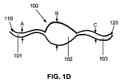
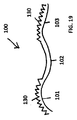
[0030] ここで図1A〜図1Eを参照すると、一実施形態において、縫合糸100は当業者に公知の任意の縫合糸であってよい。好ましい実施形態において、縫合糸100は、第1の延出部110および第2の延出部120によって画成される長さの非対称縫合糸である。縫合糸100は、幅Aを有する第1の領域101と、幅Bを有する第2の領域102と、幅Cを有する第3の領域103と、を含む。第1の領域101は第1の延出部110に配置され、第3の領域103は第2の延出部120に配置され、第2の領域102は第1の延出部110と第2の延出部120との間に配置される。第1の領域、第2の領域および第3の領域101〜103は、縫合糸100が一体であるように連続的に形成される。第2の領域102の幅Bは、第1の領域101の幅Aおよび第3の領域103の幅Cより広い。幅AおよびCは、同じ(例えば当業者に公知の従来の縫合糸の幅)であってよい。任意の非対称縫合糸の第1の領域から第2の領域への移行および任意の非対称縫合糸固定部の第2の領域から第3の領域への移行は、明確な区分けされた移行であっても、それらは、段階的もしくは滑らかな勾配移行、またはその間の任意のタイプもしくは形状の移行であってもよい。
[0030] Referring now to FIGS. 1A-1E, in one embodiment,
[0031] 縫合糸100および領域101〜103の各々の長さは、縫合糸100が軟組織の二列ノットレス修復のために使用されると、従来の縫合糸よりも広い幅Bを有する第2の領域102が、軟組織の面に配置され外側列を形成するように、あらかじめ決定される。縫合糸100の第2の領域102は、縫合糸100と軟組織との間により広い接触領域を提供し、それは、軟組織の圧力の分布を均等にし、修復対象の組織の損傷前の自然な状態における骨および軟組織の真の本来のフットプリントと同様に、より効果的に軟組織を骨へと保持する。
[0031] The length of each of
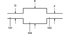
[0032] 一部の実施形態において、第1の領域101、第2の領域102および第3の領域103は、それぞれ、太さD、太さEおよび太さFを有してよい(図20を参照)。第2の領域102の太さEは、第1の領域101の太さDおよび第3の領域103の太さFより大きくてもよい。太さDと太さFとは、同じ(例えば当業者に公知の従来の縫合糸の太さ)であってよい。一実施形態において、第2の領域102のより太い太さEは、強化された材料または第1の領域101および第3の領域103の形成に使用される材料とは異なる材料の第2の領域102を形成することによって達成される。
In some embodiments, the
[0033] 非対称縫合糸100の第2の領域102は任意の適切な形状を有してよい(例えば、図1A〜1E参照)。例えば、第2の領域102は、四角形、楕円形、クローバ型、涙型または半円形の形状を有してよい。あるいは、第2の領域102は修復されている組織の輪郭が嵌合するようにカスタム成型されてもよい。形状のこのリストは図示および記載の目的のために提示された。第2の領域102のために利用できる他の形状に関して、網羅的であることも、限定するものであることも意図されない。
[0033] The
[0034] 一実施形態において、図19に示すように、第1の領域101および第3の領域103は、縫合糸100に結び目を作る、即ちループに結ばれたときに、第1の領域101の歯130と第3の領域103の歯130とが接触し、第2の領域102をしっかり留めて縫合糸100を固定するように、複数の歯130を含んでよい。この実施形態において、第1の領域、第2の領域および第3の領域101,102,103の幅A、BおよびCは、同じであっても異なっていてもよい。同様に、第1の領域、第2の領域および第3の領域101,102,103の太さD、EおよびFは、同じであっても異なっていてもよい。
In one embodiment, as shown in FIG. 19, the
[0035] 図17および図18を参照すると、ループ300は、縫合に関与する任意の公知の医療用の装置または用途と併用して使用することができる。例えば、ループ300を縫合糸固定部内に配置することができるか、別の縫合糸内でループにすることができるか、メッシュ(例えばヘルニア修復のために利用されるメッシュ)内でループにすることができるか、または1片のハードウェア(整形外科用インパクトロッドまたは関節置換において使用されるハードウェア等)へ縫合することができる。
[0035] Referring to FIGS. 17 and 18,
[0036] ループ300は、縫合糸320を収容し固定するように構成される。一実施形態において、ループ300は、ループ300の内周面に沿って配置される複数の歯310を含む。歯310がループ300の全周面に沿って配置されることを図17および図18は図示するが、歯310は、他の実施形態においてループ300の周面の一部のみに配置することができる。さらなる実施形態において、ループ300は歯310を含まない。
[0037] 縫合糸320がループ300内に収容されると、所望される位置が達成されるまで、縫合糸320を前後に摺動させることができる。縫合糸320は、上記の縫合糸100の任意の実施形態に対応する形状またはサイズを有してよい。縫合糸320は、皮膚または組織を通され、輪にされ、縫合糸の使用および適用のための任意の公知の方法に従って締められ得る。縫合糸320が、例えば縫合糸320の両方の端部を引くことによって締められると、歯310は、縫合糸320を固定するために熊の罠の操作と同様に縫合糸320をしっかり留める。ループ300が歯310を含む実施形態において、ループ300の第1の部分で提供される歯310が、第1の部分の反対のループ300の第2の部分で提供される歯310と係合すると、縫合糸320は固定される。ループ300が歯を含まない実施形態において、ループの第1の部分が第1の部分の反対のループの第2の部分に係合すると、縫合糸320は固定される。
Once the
[0038] ループ300が縫合糸320をしっかり留めると、ループ300は縫合糸320を適所にロックする。ループ300が歯310を含む実施形態において、歯310は恒久的に係合することができるか、または歯310は縫合糸320が結ばれる場合のみ係合することができる。歯310が恒久的に係合されない実施形態において、ループ300は、歯310を緩めること、縫合糸320を調整することまたは再び張力をかけること、および歯310を再び留めることによって、縫合糸を締めること、調整すること、または再び張力をかけることを可能にする。例えば、ループ300は、縫合糸320が通過する方向に沿った加圧により、歯310を緩めるかまたは留めないように構成することができる。再び張力をかけることが要求される場合、かかるループは、結び目を作ることまたは縫合糸を置き換えることなしに縫合糸を固定することも可能にする。縫合糸320の第1の延出部は、第1の縫合糸固定部200(すなわち以下のさらなる詳細中で記載されるような内側列縫合糸固定部)内でループ300経由で固定することができる。縫合糸320の第2の延出部は、第2の縫合糸固定部250(すなわち以下のさらなる詳細中で記載されるような外側列縫合糸固定部)内で固定することができる。
[0038] When the
[0039] ループ300は当業者に公知の多様な材料から作製することができる。例示的な実施形態において、ループ300は圧縮できる材料から作製される。かかる実施形態において、ループ材料は、歯310を縫合糸320へ留める前またその間に、圧縮されていない状態から圧縮された状態へ圧縮することができる。かかる圧縮は、材料が圧縮した状態から圧縮されていない状態へ跳ね返ることを可能にする。圧縮することができるかかる材料には、ポリエチレン、シリコーン、ポリエステル、ポリウレタン、ポリ乳酸、ポリグリコール酸、または任意の2つ以上のかかる材料のブレンドが含まれるが、これらに限定されない。利用される任意の材料は生体適合性であるべきである。本明細書において使用される時、生体適合性とは、材料は患者または被験者中での設置が意図され、患者中で有害効果を引き起こさないということを意味することが意図される。
The
[0040] ループ300は、軟組織を骨に、または骨を骨に固定するための装置と併用して使用することができる。これは以下でさらに詳細に記載される。あるいは、ループ300を使用して縫合糸を締め付け、組織から骨への直接的な接触なしに組織に張力をかける。組織から骨への接触なしに張力をかける、かかる縫合糸の使用の例には、骨盤の手術、膀胱挙術、ブローリフト術またはフェイスリフト術、手の手術および同種のものが含まれるが、これらに限定されない。
The
[0041] ループ300は一般的には環形状を有するとして図示されるが、ループ300は他の形状(例えば楕円形、涙型など)の形態であってよい。ループ300が自身の上に潰れて縫合糸320を固定することができる場合、任意の適切な形状を利用することができる。
Although
[0042] 図19によって記載される実施形態において、縫合糸100は皮膚または組織に通され、輪にされ、縫合糸の使用および適用のための任意の公知の方法に従って締められ得る。一実施形態において、縫合糸100が輪にされると、縫合糸100を第3の領域103で引いて第3の領域103が第1の領域101で潰れる。縫合糸100が締められると、第1の領域101および第3の領域103の歯130が係合して、縫合糸100を固定するために熊の罠の操作と同様に縫合糸100をしっかり留める。
[0042] In the embodiment described by FIG. 19, the
[0043] 一実施形態において、縫合糸100は複数の第1の延出部110および複数の第2の延出部120を含んでよい。複数の第1の延出部110は、単一の第1の縫合糸固定部200または複数の第1の縫合糸固定部200によって固定することができる。同様に、複数の第2の延出部120は、単一の第2の縫合糸固定部250または複数の第2の縫合糸固定部250によって固定することができる。この構成に従って、第2の領域102を下に引き、複数の第1の延出部110および複数の第2の延出部120によって第2の領域102の複数の位置において固定することができる。
[0043] In one embodiment,
[0044] 二列ノットレス軟組織修復のためのシステムは、縫合糸100、第1の縫合糸固定部200および第2の縫合糸固定部250を含む。第1の縫合糸固定部200および第2の縫合糸固定部250は、当業者へ公知の任意の縫合糸固定部であってよい。一実施形態において、図2〜3に示すように、第1の縫合糸固定部200は、各々の円盤2001の中心で配置された孔を横断する軸2002によって接続される2つの円盤2001を含む滑車固定部2000である。軸2002はハウジング2003に接続することができる。縫合糸100は、円盤2001の時計回りの方向に沿って軸2002のまわりを巻く。縫合糸100の張力は、軸2002に沿った縫合糸100の動きに従って変更することができる。縫合糸100が、円盤2001の時計回りの方向に沿って第1の方向に、および円盤2001の逆時計回りの方向に沿って第1の方向と反対の第2の方向に、引くことができるという点で縫合糸100は固定されない。
[0044] A system for dual row knotless soft tissue repair includes a
[0045] 別の実施形態において、図13〜図14に示すように、第1の縫合糸固定部200は、縫合糸が穴3001を介して供給されて縫合糸が穴3001内で摺動可能であるように、横断穴3001を有する縫合糸固定部3000である。第1の縫合糸固定部3000は、縫合糸がチャンネル3002内で摺動可能であるように、穴3001および穴3001と連通する縫合糸固定部3000の外面におけるチャンネル3002も含んでよい。第1の縫合糸固定部3000は、横断穴を例外として隙間がないか(図13を参照)、または中央開口部分3003を含んでよい(図14を参照)。
In another embodiment, as shown in FIGS. 13-14, the first
[0046] 別の実施形態において、図15に示すように、第1の縫合糸固定部200は、縫合糸固定部4000の挿入軸に沿った長手方向の穴を画成する内部穴4001および横断したポスト4002を含む縫合糸固定部4000である。かかる実施形態において、横断したポスト4002が縫合糸のための滑車または摺動部として働くように、縫合糸は内部穴4001内に供給され、横断したポスト4002下で通過され、縫合糸固定部4000の頂部から出る。
[0046] In another embodiment, as shown in FIG. 15, the
[0047] 第1の縫合糸固定部200は当業者に公知の多様な材料から作製することができる。例えば、第1の縫合糸固定部のために、材料は典型的には剛性材(金属、ポリマーまたはセラミック等)である。生体適合性金属には、ステンレス鋼、チタン、タンタル、アルミニウム、クロミウム、モリブデン、コバルト、銀および金または当業者に公知のかかる金属の合金が含まれるが、これらに限定されない。生体適合性ポリマーには、高密度ポリエチレン、ポリウレタンまたは当業者に公知のかかるポリマーのブレンドが含まれるが、これらに限定されない。生体適合性ポリマーには、吸収可能な材料(ポリ乳酸、ポリグリコール酸またはその混合物等)も含まれる。生体適合性セラミックには、アルミナ、シリカ、炭化シリコン、窒化シリコン、ジルコニア、およびそのうちの2種またはそれ以上の任意の混合物が含まれるが、これらに限定されない。
[0047] The
[0048] 他の実施形態において、縫合糸100が第1の方向に第1の縫合糸固定部内で通された後に、縫合糸100はロックされるか、または第2の方向にの引き戻しが阻害される。第1の代替の実施形態において、第1の縫合糸固定部200は、縫合糸100が第1の縫合糸固定部200を介して第1の方向に通されることを可能にするが、縫合糸100が第2の方向(第1の方向の反対)で引き戻されることを可能にしないチェックバルブ(不図示)である。
[0048] In another embodiment, after the
[0049] 別の実施形態において、縫合糸は、縫合糸の長さに沿って所定間隔で配置された矢じりまたは半分の矢じり(釣り針の返し等)を含む返しのある縫合糸(不図示)である。チェックバルブに類似して、矢じりは縫合糸が第1の縫合糸固定部を介して第1の方向に通されることを可能にするが、縫合糸が矢じりが(第1の方向と反対の)第2の方向に引き戻されることを可能にしない。 [0049] In another embodiment, the suture is a barbed suture (not shown) including arrowheads or half arrowheads (such as hook return) disposed at predetermined intervals along the length of the suture. is there. Similar to a check valve, the arrowhead allows the suture to be passed in a first direction through the first suture anchor, but the suture does not have an arrowhead (opposite to the first direction). ) Do not allow to be pulled back in the second direction.
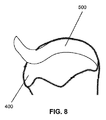
[0050] さらに別の実施形態において、第1の縫合糸固定部は実質的に図8の形状に形成される(不図示)。図8の頂部半分は第1の縫合糸固定部の方チャンバーを画成し、図8の底部半分は第1の縫合糸固定部の下方チャンバーを画成する。縫合糸を第1の縫合糸固定部の下方チャンバーに通す。縫合糸を第1の縫合糸固定部を介して引く場合、縫合糸は方チャンバーの中へ滑り込み、それは固定され、縫合糸の位置をロックする。言いかえれば、縫合糸は方チャンバーに入ると、下方チャンバーへ戻ることができず、したがって縫合糸を緩めることができない。 [0050] In yet another embodiment, the first suture anchor is formed substantially in the shape of FIG. 8 (not shown). The top half of FIG. 8 defines the chamber of the first suture anchor and the bottom half of FIG. 8 defines the lower chamber of the first suture anchor. The suture is passed through the lower chamber of the first suture anchor. When the suture is pulled through the first suture anchor, the suture slides into the relative chamber, which is anchored and locks the position of the suture. In other words, once the suture enters the relative chamber, it can not return to the lower chamber and thus can not loosen the suture.
[0051] 別の実施形態において、図4〜図7に示すように、第2の縫合糸固定部250は固定部本体1010およびプラグ1020を含む縫合糸固定部1000であってよい。縫合糸固定部1000の構成の態様は、米国特許第8,202,295号明細書および米国特許出願公開第2008/0077161号明細書(その両方は任意のおよびすべての目的のためにその全体を参照により本明細書に援用される)中で記載される。
In another embodiment, as shown in FIGS. 4-7, the
[0052] 図4〜図7を参照すると、縫合糸固定部1000は固定部本体1010およびプラグ1020を含む。固定部本体1010は、穿たれて固定部プラグ1020を受け入れる中央領域またはウェルを有する。ウェルは外面1017、内面1018および上面1016を有する壁によって囲まれる。ウェルは底部内面(すなわちウェルの底部)および底部外面(すなわち固定部本体1010の底部)も有する。固定部本体1010の内面1018はネジ山1015を有して、固定部プラグ1020の対応するネジ山1023を受け入れることができる。上面1016へ近位の壁の内面1018の頂縁部は斜面1015を有してよい。壁の外面1017は、骨または他の組織中でプラグ1020を固定するための段またはネジ山1014を有してよい。段またはネジ山1014は、全体として、固定部本体1010および縫合糸固定部1000へのアンカリング能力を提供して、縫合糸に張力をかける場合または被験者における移植の時間にわたってのいずれかで、骨または他の組織から容易に引き抜かれることを防止する。あるいは、固定部本体1010の穿たれた中央領域はネジ山が付いていないが、摩擦嵌合により固定部プラグを受け入れることができる滑らかな穴である。固定部本体1010は、固定部本体1010の中へひだをとった縫合糸を格納し、次いで摩擦嵌合した固定部プラグを挿入することができるか、または固定部本体1010は、固定部本体1010中の横断穴1012に通された縫合糸を格納して、固定部プラグ1020によって適所に固定することができる。
Referring to FIGS. 4-7,
[0053] 固定部本体1010内の横断穴1012は、縫合糸固定部1000によって固定される1本以上の縫合糸を収容するように構成される。縫合糸がウェルの底部と固定部プラグ1020の底面1026との間に固定することができるように、横断穴1012はウェルの底部に近位に構成される。横断穴1012から固定部本体1010の上面1016へ延長する溝1013が提供されて、固定部本体1010が骨中の適所にある場合に固定部本体1010を介する縫合糸の動きを可能にする。したがって、固定部本体1010が、横断穴1012に通された縫合糸により骨または他の組織の中に推進されると、縫合糸は溝1013中で動くことが可能である。縫合糸は、所望される張力へ動かされるか、またはプラグが縫合糸と係合するまで固定部本体1010中で固定部プラグ1020と係合することおよび固定部プラグ1020を推進することによって、縫合糸固定部1000中で固定され、それによって縫合糸の動きを防止することができる。縫合糸は、固定部プラグ1020の底面1026と固定部本体1010中で形成されるウェルの底部との間に固定される。
[0054] 固定部プラグ1020は、ヘッド1024と、固定部本体1010のネジ山の付いた内面1018の係合のためのネジ山の付いたポスト1023と、ヘッド1024から遠位にある底面1026と、を有してよい。固定部プラグ1020は、内面1018の斜面1015への相補的な斜面1025も有してよい。固定部プラグ1020が固定部本体1010中で完全に係合されると、斜面1025は内面1018の斜面1015と係合するように構成される。
[0054] The
[0055] 固定部プラグ1020は、相補的なドライブ装置によって係合され、その結果、固定部プラグ1020が固定部本体1010中で締められるかまたは緩めることができるように構成されてもよい。固定部プラグ1020のヘッド1024は典型的には成形されるかまたは凹領域を有して、ドライブ装置との係合を格納する。例えば、固定部プラグ1020は図4〜7中で示されるように六角形のドライブ1021を有してよいか、またはスロットのあるドライブ、Philipsドライブ、正方形のドライブ、星形のドライブ、ナットドライブ、または相補的なドライブ装置の係合のために当業者に公知の他のメカニズムを有してよい。固定部プラグ1020が固定部本体1010中で完全に係合されると、固定部プラグ1020は、固定部プラグ1020のヘッド1024の頂部が固定部本体1010の上面1016と同一平面にあるか、固定部本体1010中で凹んでいるか、または固定部本体1010より上であるように構成することができる。
The
[0056] 縫合糸固定部1000は、固定部本体1010から固定部プラグ1020を締めること、緩めること、再び締めること、および/または除去することによって、縫合糸を締めること、調整すること、または再び張力をかけることを可能にする。再び張力をかけることが要求される場合、縫合糸固定部1000は、結び目を作ることまたは縫合糸を置き換えることなしに縫合糸を固定することも可能にする。縫合糸固定部1000は、軟組織を骨へまたは骨を骨に固定するために使用することができる。
[0056] The
[0057] 縫合糸固定部1000およびプラグ1020は当業者に公知の多様な材料から作製することができる。例えば、縫合糸固定部1000のために、材料は典型的には剛性材(金属、ポリマーまたはセラミック等)である。生体適合性金属には、ステンレス鋼、チタン、タンタル、アルミニウム、クロミウム、モリブデン、コバルト、銀および金または当業者に公知のかかる金属の合金が含まれるが、これらに限定されない。生体適合性ポリマーには、高密度ポリエチレン、ポリウレタンまたは当業者に公知のかかるポリマーのブレンドが含まれるが、これらに限定されない。生体適合性ポリマーには、吸収可能な材料(ポリ乳酸、ポリグリコール酸またはその混合物等)も含まれる。生体適合性セラミックには、アルミナ、シリカ、炭化シリコン、窒化シリコン、ジルコニア、およびそのうちの2つまたはそれ以上の任意の混合物が含まれるが、これらに限定されない。
[0057]
[0058] プラグ1020は、類似の金属、ポリマーおよびセラミックから同様に調製することができるが、一部の実施形態において、固定部プラグは、圧縮できる材料から調製される。かかる実施形態において、プラグ材料は、固定部本体1010の中へのプラグの挿入の前またはその間に、圧縮されていない状態から圧縮された状態へ圧縮することができる。かかる圧縮は、材料が圧縮した状態から圧縮されていない状態へ跳ね返ることを可能にし、それによってプラグと固定部本体1010との間の摩擦嵌合を増加させる。圧縮することができるかかる材料は、ポリエチレン、シリコーン、ポリエステル、ポリウレタン、ポリ乳酸、ポリグリコール酸、またはその任意の2つ以上の材料の混合物を含むが、これらに限定されない。
[0058] The
[0059] 縫合糸固定部1000を使用して縫合糸を締め付け、組織から骨への直接的な接触なしに組織に張力をかけることができる。組織から骨への接触なしに張力をかける、かかる縫合糸の使用の例は、骨盤の手術、膀胱挙術、ブローリフト術またはフェイスリフト術、手の手術および同種のものを含むが、これらに限定されない。
[0059] The
[0060] 縫合糸100および縫合糸固定部1000を使用する方法も提供される。例えば、図4〜図7を参照すると、縫合糸固定部1000は縫合糸100を調整して保持することができる。典型的な手順において、骨の中でネストまたは孔をドリルにより開ける。次いで横断穴1012が骨中で不明瞭にならないように、固定部本体1010を、ネストの頂部で設置し挿入する。次いで縫合糸100を固定される組織を介して通し、縫合糸100の端部を横断穴1012を介して通す。次いで縫合糸100が溝1013によって導かれ、溝1013および横断穴1012を介して自由に動いているように、固定部本体1010は完全にまたは部分的にネストの中に推進することができる。次いで固定部プラグ1020は固定部本体1010中で係合され、縫合糸100がほぼ係合されるまで、固定部本体1010の中へ推進することができる。次いで縫合糸100の張力は外科医または他の医療専門家によって設定することができ、固定部プラグ1020を完全に係合させて縫合糸固定部1000内で縫合糸100を固定する。縫合糸100の張力を再び調整するために、固定部プラグ1020は固定部プラグ1020を緩めるように逆方向に推進することができ、それによって縫合糸100の自由な動きを可能にし、縫合糸100に張力をかけるプロセスを反復することができる。当業者は、複数の縫合糸100を単一の縫合糸固定部1000と併用して使用できることを認識するであろう。
[0060] A method of using
[0061] 別の態様において、装置を使用する軟組織500の二列ノットレス修復のための本明細書に記載される方法が提供される。方法は組織修復を可能にする。一部の実施形態において、本方法は、被験者の回旋腱板の真の生来のフットプリントを再生成することを試みることによって関節鏡視下の回旋腱板修復を可能にする。
[0061] In another aspect, there is provided a method as described herein for two-row knotless repair of
[0062] ここで図8〜図10を参照すると、一部の実施形態において、かかる方法は骨(上腕骨400等)の一部中に第1のトンネル201を穿孔し、上腕骨400の別の一部中に第2のトンネル251を穿孔することによって、回旋腱板床を調製することを含む。第2のトンネル251は、第1のトンネル201から所定の外側距離で配置される。第1のトンネル201と第2のトンネル251との間の所定の外側距離は、少なくとも縫合糸100の第2の領域102の長さである。第1のトンネルおよび第2のトンネル201および251を例えば上腕骨400の大結節中に穿孔することができる。
[0062] Referring now to FIGS. 8-10, in some embodiments, such a method punctures the first tunnel 201 in a portion of a bone (such as the humerus 400) and separates the humeral 400 from one another. Preparing the rotator cuff bed by piercing the
[0063] 縫合糸100の第2の延出部120は、第1のトンネル201の近傍の位置で軟組織500の上面から軟組織500の底面へ往復する。縫合糸100の第1の延出部110は軟組織500の上に配置されたままである。第1の縫合糸固定部200を第1のトンネル201の中へ設置し、上腕骨400の大結節に固定する。次いで縫合糸100を第1の縫合糸固定部200により上腕骨400に通す。縫合糸100は、第1のトンネル201の中への第1の縫合糸固定部200の挿入の前または後のいずれかで、第1の縫合糸固定部200を介して(軸2002に沿って)設置することができる。この実施形態において、第1の縫合糸固定部200は、滑車として働き、その結果、第2の延出部120の動きに応じて縫合糸100の張力を変更することができるように構成される。言いかえれば、第1の縫合糸固定部200は、円盤2001の時計回りの方向に軸2002に沿って縫合糸100の動きを支持する。
The
[0064] 第1の縫合糸固定部200を介して通過させた後、縫合糸100の第2の延出部120は、軟組織500の底面から軟組織500の上面へ往復し、それによって内側列(すなわち第1の列)を形成する。修復プロセスにおけるこの点で、縫合糸100の第1の領域101の実質的な部分は軟組織500より下でおよび上腕骨400内で配置され、一方で第2の領域102および第3の領域103は軟組織500の上に配置される。縫合糸100の第1の延出部110を第2の領域102を介して通過させ、それによって軟組織500の周囲で緩いループを生成する(図11を参照)。第1の延出部110が第2の領域102を通されると、ループは組織500にわたって引き込まれ、第1の縫合糸固定部200に対して固定される。縫合糸100および/または軟組織500の再配置を未完成にできるので、このループは結び目ではない。
After passing through the
[0065] 次いで第2の縫合糸固定部250を第2のトンネル251の中へ設置し、上腕骨400の大結節に固定する。縫合糸100の第2の延出部120は、軟組織500を介して往復されずに、第2の縫合糸固定部250を介して設置される。その代りに、縫合糸100の第2の延出部120を軟組織500の外側面に沿って延長し、第2のトンネル251の中への第2の縫合糸固定部250の挿入の前または後のいずれかで、第2の縫合糸固定部250を介して設置した。修復プロセスにおけるこの点で、縫合糸100の第2の領域102は軟組織500の上面を横切って配置され、一方で第3の領域103の実質的な部分は軟組織500より下でおよび上腕骨400内で配置される。外側列(すなわち第2列)は第2の領域102によって部分的に画成される。
Next, the second
[0066] 次いで縫合糸100に張力をかけ、それによって軟組織500に張力をかける。第2の縫合糸固定部250が上記の縫合糸固定部1000である実施形態において、縫合糸100は、固定部本体1010中の固定部プラグ1020の位置の中へ係合しロックすることによって張力をかけることができる。この工程を反復して縫合糸100の張力を変更することができ、したがって縫合糸100および軟組織500に再び張力をかける。この工程は、上腕骨400に対して縫合糸100を効果的に圧縮し、第1の延出部110に近位軟組織500を第1の縫合糸固定部200に対して引き下げ、外側軟組織500を第2の領域102経由で圧縮し、軟組織500を上腕骨400固定する。
The
[0067] 上記の軟組織500の二列ノットレス修復のための方法において、内側縫合糸は内側列で組織を引き下げる。縫合糸100が第2の縫合糸固定部250(すなわち外側縫合糸固定部)によって外側に固定されロックされると、内側縫合糸は、第1の縫合糸固定部200(すなわち内側縫合糸固定部)の引張力によって固定される。言いかえれば、縫合糸100は2点の接触(すなわち内側列および外側列)を提供するが、縫合糸100は単一の点(すなわち第2の縫合糸固定部250)でのみロックされる。第2の縫合糸固定部250は縫合糸100をロックするが、内側縫合糸も内側に固定する。ループ300を含む実施形態において、ループ300は第1の縫合糸固定部200で提供され、縫合糸100が第2の縫合糸固定部250によって外側に固定されロックされると、ループした側面は締められるおよび/またはロックされる。
[0067] In the method for dual knotless repair of
[0068] 縫合糸100、第1の縫合糸固定部200および第2の縫合糸固定部250は、持ち運び可能な縫合糸キットで提供することができる。縫合糸キットは、当該技術分野において公知の追加の装置(例えばメス、はさみ、プローブまたはピンセット)を有してよい。縫合糸100は、従来の縫合糸または上記の実施形態に係る非対称縫合糸であってよい。第1の縫合糸固定部200は、縫合糸が少なくとも1つの方向に第1の縫合糸固定部200を介して動くことを可能にするように構成される任意の公知の縫合糸固定部であってよい。例えば、第1の縫合糸固定部200は図2〜3に示す縫合糸固定部であってよい。第2の縫合糸固定部250は縫合糸を固定するように構成される任意の公知の縫合糸固定部であってよい。例えば、第2の縫合糸固定部250は述される縫合糸固定部1000であってよく、それは縫合糸100を調整して保持することができる。
[0068] The
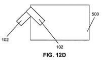
[0069] 当業者は、上記のシステムおよび方法を利用して上腕骨以外の骨格の近傍の位置で身体中の任意の軟組織を修復できることを認識するであろう。加えて、図12A〜12Dを参照すると、当業者は、二列ノットレス縫合糸の平行なセットまたは交差するセットを使用して軟組織を修復するように、複数のシステムを利用できることを認識するであろう。当業者は、かかる代替の構成において、複数の縫合糸固定部が複数の縫合糸と併用して使用されることを認識するであろう。任意の数の縫合糸固定部および縫合糸を利用することができる。 [0069] Those skilled in the art will recognize that any soft tissue in the body can be repaired at a location near a skeleton other than the humerus utilizing the systems and methods described above. In addition, with reference to FIGS. 12A-12D, one skilled in the art will recognize that multiple systems can be utilized to repair soft tissue using parallel or intersecting sets of dual row knotless sutures. I will. One skilled in the art will recognize that in such alternative configurations, multiple suture anchors may be used in conjunction with multiple sutures. Any number of suture anchors and sutures can be utilized.
[0070] この開示の目的のために、および特段の定めのない限り、「1つの(a)」または「1つの(an)」は「1つまたは複数」を意味する。 [0070] For the purposes of this disclosure, and unless otherwise specified, "one (a)" or "an" means "one or more."
[0071] 特定の実施形態が図示され記載されたが、変化および修飾は、以下の請求項中で定義されるようにその広範囲の態様の技術から逸脱せずに、当該技術分野における通常の技能に従ってその中で行なうことができることを理解すべきである。 [0071] While specific embodiments have been illustrated and described, changes and modifications may be made within the ordinary skill in the art without departing from the technology of the broad aspect thereof as defined in the following claims. It should be understood that it can be done according to
[0072] 例示的に本明細書に記載された実施形態は、本明細書において具体的に開示されない任意の要素または限定の非存在下において適切に実践することができる。したがって、例えば、「含む」、「備える」、「有する」などの用語は、限定されずに拡張的に解釈される。加えて、本明細書において用いられた用語および表現は限定の用語ではなく記載の用語として使用され、かかる用語および表現を使用して、示され記載された特色の任意の均等物またはその部分を除外することは意図しないが、様々な修飾が請求された技術の範囲内で可能であることが認識される。加えて、「〜から本質的になる」という句には、具体的に列挙された要素、および請求された技術の基礎的および新規の特徴に実質的に影響しないそれらの追加の要素が含まれることが理解されるであろう。「〜からなる」という句は規定されない任意の要素を除外する。理解されるように、「含む」という用語が請求項で使用される場合は常に、一部の実施形態において「〜から本質的になる」または「〜からなる」という用語と置換することができる。 [0072] The embodiments described herein illustratively can be suitably practiced in the absence of any element or limitation not specifically disclosed herein. Thus, for example, the terms "including," "including," "having," etc. are to be interpreted expansively, without limitation. In addition, the terms and phrases used herein are used as the term of description rather than the term of limitation, and using such terms and phrases any equivalent of the features shown and described or portions thereof It is recognized that various modifications are possible within the scope of the claimed technology, not intended to be excluded. In addition, the phrase “consisting essentially of” includes the specifically recited elements, and those additional elements that do not materially affect the basic and novel characteristics of the claimed technology. It will be understood. The phrase "consisting of" excludes any element not specified. As will be appreciated, whenever the term "comprising" is used in the claims, it may be substituted in some embodiments with the term "consisting essentially of" or "consisting of" .
[0073] 本開示は、本出願に記載した特定の実施形態に関して限定されない。当業者に明らかなように、多くの変更および変形をその趣旨および範囲から逸脱せずに行なうことができる。本明細書において列挙されたものに加えて、本開示の範囲内で機能的に同等の方法および組成物は前述の記載から当業者に明らかでなる。かかる修飾および変動は添付の請求項の範囲以内であることが意図される。本開示は、かかる請求項が権利化される均等物の全範囲と共に、添付の請求項の条項によってのみ限定される。本開示は、特定の方法、試薬、化合物、組成物または生物学的システム(それは当然変動し得る)へ限定されていないことを理解すべきである。本明細書において使用される用語は特定の実施形態を記載するのみの目的のためのものであり、限定するとは意図されないことも理解すべきである。 [0073] The present disclosure is not limited with respect to the specific embodiments described in the present application. As is apparent to those skilled in the art, many modifications and variations can be made without departing from the spirit and scope thereof. Functionally equivalent methods and compositions within the scope of the disclosure, in addition to those enumerated herein, will be apparent to those skilled in the art from the foregoing description. Such modifications and variations are intended to be within the scope of the appended claims. The present disclosure is limited only by the terms of the appended claims, along with the full scope of equivalents to which such claims are entitled. It is to be understood that the present disclosure is not limited to particular methods, reagents, compounds compositions or biological systems, which may, of course, be varied. It is also to be understood that the terminology used herein is for the purpose of describing particular embodiments only and is not intended to be limiting.
[0074] 加えて、本開示の特色または態様がマーカッシュグループにより記載される場合、その結果として、本開示はマーカッシュグループのうちの任意の個別の部材または部材のサブグループに関しても記載されることを当業者は認識するであろう。 [0074] In addition, when the features or aspects of the present disclosure are described by a Markush group, as a result, the present disclosure is also described with respect to any individual member or sub-group of members of the Markush group. One skilled in the art will recognize.
[0075] 任意のおよびすべての目的のために、特に書面の記載を提供する点で、当業者によって理解されるように、本明細書において開示されるすべての範囲は、任意のおよびすべての部分範囲ならびにその部分範囲の組み合わせも包含する。任意のリストされた範囲は、少なくとも2等分、3等分、4等分、5等分、10等分などをされている同じ範囲を十分に記載し有効にすることを容易に認識することができる。非限定例として、本明細書において論じられる各々の範囲は、下方3分の1、中央3分の1および方3分の1などへと容易に分けることができる。当業者によっても理解されるように、「まで」、「少なくとも」、「より大きい」、「未満」および同種のもの等のすべての文言は、列挙された数を含み、続いてで論じられるように部分範囲へと分けることができる範囲を指す。最終的に、当業者によって理解されるように、範囲は個別の部材を含む。 [0075] As understood by those skilled in the art, for any and all purposes, and in particular in providing a written description, all ranges disclosed herein are any and all parts Also included are combinations of ranges as well as subranges thereof. Any of the listed ranges should be readily recognizable as sufficiently describing and validating the same range being at least two, three, four, five, ten, etc. Can. As a non-limiting example, each of the ranges discussed herein can be easily divided into lower third, middle third, one third, etc. As will also be appreciated by those skilled in the art, all words such as "up", "at least", "greater than", "less than" and the like include the recited numbers and will be discussed subsequently Refers to the range that can be divided into subranges. Finally, as understood by one of ordinary skill in the art, the range includes individual members.
[0076] すべての公報、特許出願、交付済み特許、およびこの明細書において言及される他の文書は、あたかも各々の個別の公報、特許出願、交付済み特許または他の文書のその全体が参照により援用されることが具体的に個別に示されるように、参照により本明細書に援用される。参照により援用される文書中に含まれる定義は、それらがこの開示における定義と矛盾する程度まで除外される。 [0076] All publications, patent applications, issued patents, and other documents mentioned in this specification are referred to as if each individual publication, patent application, issued patent or other document is in its entirety It is incorporated herein by reference as specifically incorporated by reference. Definitions included in documents incorporated by reference are excluded to the extent that they conflict with the definitions in this disclosure.
[0077] 他の実施形態は以下の特許請求の範囲において説明される。 [0077] Other embodiments are set forth in the following claims.
Claims (13)
縫合糸であって、前記縫合糸の第1の端部の近傍の第1の領域と、第2の領域と、前記縫合糸の第2の端部の近傍の第3の領域と、を備える、縫合糸と、
骨の第2の位置に配置されるように構成された外側縫合糸固定部と、を備え、
前記縫合糸が、
第1の幅を有する前記第1の領域と、
第2の幅を有する前記第2の領域と、
第3の幅を有する前記第3の領域と、によって少なくとも部分的に規定され、
前記第2の領域の前記第2の幅が、前記第1の領域の前記第1の幅および前記第3の領域の前記第3の幅より広く、
前記縫合糸が、前記内側縫合糸固定部および前記外側縫合糸固定部に通されて、軟組織の底面から前記軟組織の上面まで前記軟組織に通されるように構成された内側列、および、前記軟組織の前記上面を横切って置かれるように構成された外側列を形成し、前記外側列は、前記内側縫合糸固定部と前記外側縫合糸固定部との間に延在する方向に形成され、
前記縫合糸の前記第2の領域は、前記内側縫合糸固定部と前記外側縫合糸固定部との間に延在する方向に前記外側列を形成する、軟組織の修復のためのシステム。 An inner suture anchor configured to be placed in a first position on bone;
A suture, comprising a first region near the first end of the suture, a second region, and a third region near the second end of the suture. , Sutures,
An outer suture anchor configured to be placed in the second position of the bone;
The suture is
The first region having a first width;
Said second region having a second width;
At least partially defined by the third region having a third width,
The second width of the second area is wider than the first width of the first area and the third width of the third area,
An inner row configured to pass the suture through the inner suture anchor and the outer suture anchor to pass through the soft tissue from a bottom surface of the soft tissue to an upper surface of the soft tissue; Forming an outer row configured to be placed transversely to the upper surface of the upper layer, the outer row being formed in a direction extending between the inner suture fixing portion and the outer suture fixing portion;
A system for soft tissue repair wherein the second region of the suture forms the outer row in a direction extending between the inner suture anchor and the outer suture anchor.
第1の幅を有する第1の領域と、
第2の幅を有する第2の領域と、
第3の幅を有する第3の領域と、によって少なくとも部分的に規定され、
前記第2の領域の前記第2の幅が、前記第1の領域の前記第1の幅および前記第3の領域の前記第3の幅より広い、請求項1に記載のシステム。 The at least one additional suture further comprises at least one additional suture,
A first region having a first width;
A second region having a second width;
At least partially defined by a third region having a third width,
The system of claim 1, wherein the second width of the second region is wider than the first width of the first region and the third width of the third region.
前記第3の領域は複数の歯を有し、
前記縫合糸がループ状に結ばれると、前記第1の領域の前記複数の歯が前記第3の領域の前記複数の歯に係合して、前記縫合糸の前記第2の領域を固定するように構成される、請求項1に記載のシステム。 The first area has a plurality of teeth,
The third region has a plurality of teeth,
When the suture is tied in a loop, the plurality of teeth in the first region engage the plurality of teeth in the third region to secure the second region of the suture The system of claim 1 configured as:
Applications Claiming Priority (5)
| Application Number | Priority Date | Filing Date | Title |
|---|---|---|---|
| US201261709293P | 2012-10-03 | 2012-10-03 | |
| US61/709,293 | 2012-10-03 | ||
| US201361792026P | 2013-03-15 | 2013-03-15 | |
| US61/792,026 | 2013-03-15 | ||
| PCT/US2013/063111 WO2014055678A1 (en) | 2012-10-03 | 2013-10-02 | Suture for soft tissue repair |
Publications (3)
| Publication Number | Publication Date |
|---|---|
| JP2016500527A JP2016500527A (en) | 2016-01-14 |
| JP2016500527A5 JP2016500527A5 (en) | 2016-09-08 |
| JP6425654B2 true JP6425654B2 (en) | 2018-11-21 |
Family
ID=50435411
Family Applications (1)
| Application Number | Title | Priority Date | Filing Date |
|---|---|---|---|
| JP2015535765A Active JP6425654B2 (en) | 2012-10-03 | 2013-10-02 | Suture for soft tissue repair |
Country Status (6)
| Country | Link |
|---|---|
| US (1) | US9724085B2 (en) |
| EP (1) | EP2903537A4 (en) |
| JP (1) | JP6425654B2 (en) |
| CN (1) | CN105007830B (en) |
| CA (2) | CA2886986C (en) |
| WO (1) | WO2014055678A1 (en) |
Families Citing this family (8)
| Publication number | Priority date | Publication date | Assignee | Title |
|---|---|---|---|---|
| US10820918B2 (en) | 2015-07-17 | 2020-11-03 | Crossroads Extremity Systems, Llc | Transosseous guide and method |
| US9962174B2 (en) | 2015-07-17 | 2018-05-08 | Kator, Llc | Transosseous method |
| US10154868B2 (en) | 2015-07-17 | 2018-12-18 | Kator, Llc | Transosseous method |
| US10143462B2 (en) | 2015-08-04 | 2018-12-04 | Kator, Llc | Transosseous suture anchor method |
| CN109394284A (en) * | 2017-08-17 | 2019-03-01 | 北京德益达美医疗科技有限公司 | All fronts holdfast |
| CN108852439B (en) * | 2018-07-27 | 2024-09-13 | 谭雄进 | Suture line tissue fixing device |
| CN115426956A (en) * | 2020-03-27 | 2022-12-02 | 爱德华兹生命科学公司 | Suture tension distribution |
| US11350926B1 (en) * | 2021-12-16 | 2022-06-07 | Christopher Ninh | Continuous loop suture assembly and related surgical techniques |
Family Cites Families (23)
| Publication number | Priority date | Publication date | Assignee | Title |
|---|---|---|---|---|
| US2093145A (en) | 1936-12-17 | 1937-09-14 | Davis & Geck Inc | Surgical suture or ligature |
| US5645568A (en) * | 1995-11-20 | 1997-07-08 | Medicinelodge, Inc. | Expandable body suture |
| US7887551B2 (en) * | 1999-12-02 | 2011-02-15 | Smith & Nephew, Inc. | Soft tissue attachment and repair |
| US7445634B2 (en) | 2000-10-27 | 2008-11-04 | Warsaw Orthopedic, Inc. | Annulus repair systems and methods |
| US7892256B2 (en) * | 2001-09-13 | 2011-02-22 | Arthrex, Inc. | High strength suture tape |
| US20060079904A1 (en) | 2004-10-13 | 2006-04-13 | Raymond Thal | Multirow knotless suture anchor assembly |
| US7658751B2 (en) * | 2006-09-29 | 2010-02-09 | Biomet Sports Medicine, Llc | Method for implanting soft tissue |
| US20070219558A1 (en) | 2006-03-15 | 2007-09-20 | Allen Deutsch | Method and apparatus for arthroscopic surgery using suture anchors |
| US20080009900A1 (en) * | 2006-06-12 | 2008-01-10 | Kfx Medical Corporation | Surgical grasping device |
| US8202295B2 (en) | 2006-07-20 | 2012-06-19 | Kaplan Lee D | Surgical instruments |
| CA2657619A1 (en) | 2006-07-20 | 2008-01-24 | Lee D. Kaplan | Surgical instruments |
| US8932327B2 (en) * | 2008-04-01 | 2015-01-13 | Covidien Lp | Anchoring device |
| US20090259251A1 (en) * | 2008-04-11 | 2009-10-15 | Cohen Matthew D | Loop suture |
| US7967841B2 (en) * | 2008-06-02 | 2011-06-28 | Ethicon, Inc. | Methods for using looped tissue-grasping devices |
| US20100106254A1 (en) * | 2008-10-23 | 2010-04-29 | Delsignore Jeanne L | Surgical implantable stabilizer sling for basal joint arthroplasty |
| US8231653B2 (en) | 2009-03-31 | 2012-07-31 | Arthrex, Inc. | Method of forming knotless double row construct with graft or patch fixed under repair site |
| US8690915B2 (en) * | 2010-11-24 | 2014-04-08 | Arthrocare Corporation | Suture |
| US8881635B2 (en) | 2011-02-02 | 2014-11-11 | Syntorr Inc. | Variable denier yarn and suture |
| RU2746457C2 (en) | 2011-03-23 | 2021-04-14 | ЭТИКОН ЭлЭлСи | Self-retaining suture with an adjustable loop |
| US9301745B2 (en) * | 2011-07-21 | 2016-04-05 | Arthrex, Inc. | Knotless suture constructs |
| US9737292B2 (en) | 2012-06-22 | 2017-08-22 | Arthrex, Inc. | Knotless suture anchors and methods of tissue repair |
| US20140039551A1 (en) | 2012-08-03 | 2014-02-06 | Joseph P. Donahue | Suture Anchor Device and Methods of Use |
| US9763655B2 (en) | 2012-09-20 | 2017-09-19 | Medos International Sarl | Systems, devices, and methods for securing tissue using hard anchors |
-
2013
- 2013-10-02 JP JP2015535765A patent/JP6425654B2/en active Active
- 2013-10-02 WO PCT/US2013/063111 patent/WO2014055678A1/en active Application Filing
- 2013-10-02 CA CA2886986A patent/CA2886986C/en active Active
- 2013-10-02 EP EP13843242.2A patent/EP2903537A4/en not_active Ceased
- 2013-10-02 US US14/394,351 patent/US9724085B2/en active Active
- 2013-10-02 CA CA3032447A patent/CA3032447A1/en not_active Abandoned
- 2013-10-02 CN CN201380061364.4A patent/CN105007830B/en active Active
Also Published As
| Publication number | Publication date |
|---|---|
| CA3032447A1 (en) | 2014-04-10 |
| US9724085B2 (en) | 2017-08-08 |
| US20150088196A1 (en) | 2015-03-26 |
| CN105007830A (en) | 2015-10-28 |
| CN105007830B (en) | 2018-02-16 |
| CA2886986A1 (en) | 2014-04-10 |
| CA2886986C (en) | 2019-03-19 |
| JP2016500527A (en) | 2016-01-14 |
| EP2903537A4 (en) | 2016-10-19 |
| WO2014055678A1 (en) | 2014-04-10 |
| EP2903537A1 (en) | 2015-08-12 |
Similar Documents
| Publication | Publication Date | Title |
|---|---|---|
| JP6425654B2 (en) | Suture for soft tissue repair | |
| US9999421B2 (en) | Suture for soft tissue repair | |
| US11648004B2 (en) | Knotless soft tissue devices and techniques | |
| US11723648B2 (en) | Method and apparatus for soft tissue fixation | |
| US20210401425A1 (en) | Self-Cinching Suture Anchors, Systems, and Methods | |
| US7455683B2 (en) | Methods and devices for repairing triangular fibrocartilage complex tears | |
| US8597336B2 (en) | Apparatus for discrete tissue anchoring for soft tissue repair and method of use | |
| US8814905B2 (en) | Surgical filament snare assemblies | |
| US9451942B2 (en) | Insertion tool for knotless suture anchor for soft tissue repair and method of use | |
| US20220079627A1 (en) | Knotless syndesmosis system | |
| AU2017313744A1 (en) | Device for securing suture to an anchor body of a suture anchor | |
| US20220313239A1 (en) | Implantable repair devices |
Legal Events
| Date | Code | Title | Description |
|---|---|---|---|
| A521 | Request for written amendment filed |
Free format text: JAPANESE INTERMEDIATE CODE: A523 Effective date: 20160719 |
|
| A621 | Written request for application examination |
Free format text: JAPANESE INTERMEDIATE CODE: A621 Effective date: 20160719 |
|
| A131 | Notification of reasons for refusal |
Free format text: JAPANESE INTERMEDIATE CODE: A131 Effective date: 20170417 |
|
| A977 | Report on retrieval |
Free format text: JAPANESE INTERMEDIATE CODE: A971007 Effective date: 20170421 |
|
| A521 | Request for written amendment filed |
Free format text: JAPANESE INTERMEDIATE CODE: A523 Effective date: 20170712 |
|
| A131 | Notification of reasons for refusal |
Free format text: JAPANESE INTERMEDIATE CODE: A131 Effective date: 20171211 |
|
| A521 | Request for written amendment filed |
Free format text: JAPANESE INTERMEDIATE CODE: A523 Effective date: 20180305 |
|
| A131 | Notification of reasons for refusal |
Free format text: JAPANESE INTERMEDIATE CODE: A131 Effective date: 20180611 |
|
| A521 | Request for written amendment filed |
Free format text: JAPANESE INTERMEDIATE CODE: A523 Effective date: 20180906 |
|
| TRDD | Decision of grant or rejection written | ||
| A01 | Written decision to grant a patent or to grant a registration (utility model) |
Free format text: JAPANESE INTERMEDIATE CODE: A01 Effective date: 20180925 |
|
| A61 | First payment of annual fees (during grant procedure) |
Free format text: JAPANESE INTERMEDIATE CODE: A61 Effective date: 20181023 |
|
| R150 | Certificate of patent or registration of utility model |
Ref document number: 6425654 Country of ref document: JP Free format text: JAPANESE INTERMEDIATE CODE: R150 |
|
| R250 | Receipt of annual fees |
Free format text: JAPANESE INTERMEDIATE CODE: R250 |
|
| R250 | Receipt of annual fees |
Free format text: JAPANESE INTERMEDIATE CODE: R250 |
|
| R250 | Receipt of annual fees |
Free format text: JAPANESE INTERMEDIATE CODE: R250 |
|
| R250 | Receipt of annual fees |
Free format text: JAPANESE INTERMEDIATE CODE: R250 |