JP6425552B2 - Output control method of pulse arc welding - Google Patents
Output control method of pulse arc welding Download PDFInfo
- Publication number
- JP6425552B2 JP6425552B2 JP2015008201A JP2015008201A JP6425552B2 JP 6425552 B2 JP6425552 B2 JP 6425552B2 JP 2015008201 A JP2015008201 A JP 2015008201A JP 2015008201 A JP2015008201 A JP 2015008201A JP 6425552 B2 JP6425552 B2 JP 6425552B2
- Authority
- JP
- Japan
- Prior art keywords
- period
- welding
- value
- current
- peak
- Prior art date
- Legal status (The legal status is an assumption and is not a legal conclusion. Google has not performed a legal analysis and makes no representation as to the accuracy of the status listed.)
- Expired - Fee Related
Links
Images



Landscapes
- Arc Welding Control (AREA)
Description
本発明は、溶接ワイヤを送給し、ピーク期間中のピーク電流及びベース期間中のベース電流を1パルス周期とする溶接電流を通電して溶接するパルスアーク溶接の出力制御方法に関するものである。 The present invention relates to a power control method of pulse arc welding in which a welding wire is fed and welding is performed with a welding current having a peak current in a peak period and a base current in a base period as one pulse cycle.
溶接ワイヤを一定の速度で送給し、ピーク期間中のピーク電流及びベース期間中のベース電流を1パルス周期とするパルス波形の溶接電流を通電してアークを発生させて溶接する消耗電極式パルスアーク溶接方法が広く使用されている。このパルスアーク溶接方法は、鉄鋼、ステンレス鋼、アルミニウム等の種々の金属材料に対して、スパッタ発生量の少ない高品質の溶接を高効率に行うことができる。 A consumable electrode type pulse that generates welding arc by supplying welding current of a pulse waveform that feeds welding wire at a constant speed, and makes the pulse current with one pulse cycle the peak current in the peak period and the base current in the base period. Arc welding methods are widely used. This pulse arc welding method can efficiently perform high-quality welding with less spatter generation amount to various metal materials such as steel, stainless steel, and aluminum.
図5は、消耗電極式パルスアーク溶接における定常溶接期間中の電流・電圧波形図である。同図(A)はアークを通電する溶接電流Iwの波形を示し、同図(B)は溶接ワイヤと母材との間に印加する溶接電圧Vwの波形を示す。以下、同図を参照して説明する。 FIG. 5 is a current-voltage waveform diagram during steady-state welding in consumable electrode type pulse arc welding. The figure (A) shows the waveform of the welding current Iw which energizes an arc, and the figure (B) shows the waveform of the welding voltage Vw applied between a welding wire and a base material. This will be described below with reference to the same figure.
時刻t1〜t2のピーク期間Tp中は、同図(A)に示すように、傾斜を有して立上り、溶滴を形成し移行させるために臨界値以上の定常ピーク電流値に設定されたピーク電流Ipが通電し、同図(B)に示すように、傾斜を有して立上り、アーク長に比例したピーク電圧Vpが印加する。時刻t2〜t3のベース期間Tb中は、同図(A)に示すように、傾斜を有して立下り、溶滴を形成しないために臨界値未満の定常ベース電流値に設定されたベース電流Ibが通電し、同図(B)に示すように、傾斜を有して立下り、アーク長に比例したベース電圧Vbが印加する。時刻t1〜t3を1パルス周期Tfとして繰り返して溶接が行われる。 During the peak period Tp from time t1 to t2, as shown in FIG. 6A, the peak rises with a slope, and is a peak set to a steady-state peak current value that is equal to or greater than the critical value in order to form and transfer droplets. The current Ip flows, and as shown in FIG. 6B, it rises with a slope, and a peak voltage Vp proportional to the arc length is applied. During the base period Tb from time t2 to time t3, as shown in FIG. 6A, it falls with a slope, and the base current is set to a steady base current value less than the critical value so as not to form a droplet. Ib is energized, and as shown in the figure (B), it falls with a slope, and a base voltage Vb proportional to the arc length is applied. Welding is performed by repeating time t1 to t3 as one pulse cycle Tf.
溶接ワイヤがステンレス鋼用の直径1.2mmのメタル系コアードワイヤである場合の各波形パラメータは、例えば以下のようになる。ピーク電流Ip=450A、立上りを含むピーク期間Tp=2.0ms、パルス周期Tf=3.0〜10.0ms、ベース電流Ib=50A、立上り期間及び立下り期間=0.5msとなる。 Each waveform parameter in the case where the welding wire is a metal-based cored wire with a diameter of 1.2 mm for stainless steel is, for example, as follows. The peak current Ip = 450 A, the peak period Tp = 2.0 ms including the rise, the pulse period Tf = 3.0 to 10.0 ms, the base current Ib = 50 A, the rise period and the fall period = 0.5 ms.
ピーク期間Tp中は、溶接ワイヤの先端が溶融されて溶滴が成長すると共に、溶滴の上部にピンチ力によるくびれが次第に形成される。そして、時刻t2にベース期間Tbに入り、溶接電流Iwが立ち下ってベース電流Ibに収束した後の時刻t21において、溶滴が溶融池に移行する。この移行時には、溶滴が細長く伸びた形状になり溶融池と接触する場合があり、このときに短時間(多くは0.2ms未満)の短絡が発生する。したがって、同図(B)に示すように、時刻t21において、溶接電圧Vwが数Vとなり、短絡が発生している。同図(A)に示すように、溶接電流Iwは、短絡が発生した時刻t21から所定時間後に増加し、短絡が終了する時刻t22に通常値に戻る。所定時間は0.1ms程度である。溶接電流Iwを増加させる理由は、早期に短絡を解除してアーク発生状態に戻すためである。 During the peak period Tp, the tip of the welding wire is melted to grow a droplet, and a pinching portion is gradually formed at the top of the droplet. Then, at time t2, the base period Tb is entered, and at time t21 after the welding current Iw falls and converges to the base current Ib, the droplet shifts to the molten pool. During this transition, the droplet may be elongated and in contact with the molten pool, and a short circuit (often less than 0.2 ms) may occur. Therefore, as shown in FIG. 6B, at time t21, the welding voltage Vw becomes several volts, and a short circuit occurs. As shown in FIG. 6A, the welding current Iw increases after a predetermined time from time t21 when the short circuit occurs, and returns to the normal value at time t22 when the short circuit ends. The predetermined time is about 0.1 ms. The reason for increasing the welding current Iw is to release the short circuit early and return to the arc generation state.
パルスアーク溶接を含む消耗電極式アーク溶接では、溶接中のアーク長を適正値に維持することが良好な溶接品質を得るために重要である。このアーク長制御は、以下のように行われる。同図(B)に示す溶接電圧の平均値Vavは平均アーク長に略比例する。このために、溶接電圧平均値Vavを検出し、この溶接電圧平均値Vavが適正な平均アーク長に相当する値に設定された溶接電圧設定値Vr(図示は省略)と等しくなるように、上記のパルス周期Tf(周波数変調制御)又はピーク期間Tp(パルス幅変調制御)をフィードバック制御によって変化させている。 In consumable electrode type arc welding including pulse arc welding, it is important to maintain an appropriate arc length during welding in order to obtain good welding quality. This arc length control is performed as follows. The average value Vav of the welding voltage shown to the figure (B) is substantially proportional to average arc length. For this purpose, the welding voltage average value Vav is detected, and the welding voltage average value Vav is equal to the welding voltage setting value Vr (not shown) set to a value corresponding to an appropriate average arc length. The pulse period Tf (frequency modulation control) or the peak period Tp (pulse width modulation control) is changed by feedback control.
周波数変調制御では、ピーク期間Tp、ピーク電流Ip及びベース電流Ibが波形パラメータとなり、所定値に設定される。そして、パルス周期Tf(ベース期間Tb)がフィードバック制御される。 In the frequency modulation control, the peak period Tp, the peak current Ip and the base current Ib become waveform parameters and are set to predetermined values. Then, the pulse period Tf (base period Tb) is feedback-controlled.
パルス幅変調制御では、ピーク電流Ip、パルス周期Tf及びベース電流Ibが波形パラメータとなり、所定値に設定される。そして、ピーク期間(パルス幅)Tpがフィードバック制御される。 In the pulse width modulation control, the peak current Ip, the pulse period Tf and the base current Ib become waveform parameters and are set to predetermined values. Then, the peak period (pulse width) Tp is feedback-controlled.
上記の溶接電圧平均値Vavは、溶接電圧Vwを検出してローパスフィルタ(カットオフ周波数1〜10Hz程度)に通すことによって検出される。 The welding voltage average value Vav is detected by detecting the welding voltage Vw and passing it through a low pass filter (cutoff frequency of about 1 to 10 Hz).
各変調制御において、波形パラメータは、1パルス周期中に1つの溶滴が移行するいわゆる1パルス周期1溶滴移行状態になるように適正値に設定される。
In each modulation control, the waveform parameter is set to an appropriate value so as to be a so-called 1
特許文献1の発明では、パルスアーク溶接において、アーク発生から所定期間中は、ピーク電流の傾きを本溶接時に比べて緩める。これにより、アークスタート時の磁気吹きを抑制することで、アーク切れを抑制することができる。
In the invention of
パルスアーク溶接において、アークスタート後の過渡期間中に、アーク長が突然急速に長くなり、溶接状態が不安定になる現象がときどき発生する。そして、アーク長が非常に長くなるために、アーク切れ又は給電チップへの溶着に至る場合もある。このアーク長が急速に長くなる現象は、アークスタート後の過渡期間中に発生することが多いが、定常溶接期間中にも発生する場合がある。 In pulse arc welding, during the transition period after arc start, the arc length suddenly and rapidly increases, and the phenomenon that the welding state becomes unstable sometimes occurs. And since the arc length becomes very long, it may lead to arc breakage or welding to the feed tip. The phenomenon that the arc length rapidly increases often occurs during the transition period after the arc start, but may also occur during the steady welding period.
そこで、本発明では、アーク長が突然急速に長くなる現象を抑制して、安定した溶接状態にすることができるパルスアーク溶接の出力制御方法を提供することを目的とする。 Therefore, it is an object of the present invention to provide an output control method of pulse arc welding capable of achieving a stable welding state by suppressing a phenomenon in which the arc length suddenly and rapidly increases.
上述した課題を解決するために、請求項1の発明は、
溶接ワイヤを送給し、ピーク期間中のピーク電流及びベース期間中のベース電流を1パルス周期とする溶接電流を通電して溶接するパルスアーク溶接の出力制御方法において、
前記ピーク期間中の溶接電圧が予め定めた基準電圧値以上になったときは、前記ピーク電流を予め定めた減少値だけ減少させ、かつ、前記ベース電流を予め定めた増加値だけ増加させる、
ことを特徴とするパルスアーク溶接の出力制御方法である。
In order to solve the problems described above, the invention of
In the power control method of pulse arc welding, a welding wire is fed, and welding is performed by applying a welding current having a peak current in a peak period and a base current in a base period as one pulse period,
When the welding voltage in the peak period becomes equal to or higher than a predetermined reference voltage value, the peak current is decreased by a predetermined decrease value, and the base current is increased by a predetermined increase value.
It is an output control method of pulse arc welding characterized by the above.
請求項2の発明は、前記減少値は、前記溶接ワイヤの単位長抵抗値に基づいて設定される、
ことを特徴とする請求項1記載のパルスアーク溶接の出力制御方法である。
In the invention of
It is an output control method of pulse arc welding according to
請求項3の発明は、アーク長制御が周波数変調制御であるときは、前記増加値は、前記ピーク電流を減少させている期間中の前記パルス周期の平均値と前記ピーク電流を減少させていない期間中の前記パルス周期の平均値との差が所定値未満になるように設定される、
ことを特徴とする請求項1又は2記載のパルスアーク溶接の出力制御方法である。
The invention according to
It is an output control method of pulse arc welding according to
請求項4の発明は、アーク長制御がパルス幅変調制御であるときは、前記増加値は、前記ピーク電流を減少させている期間中の前記ピーク期間の平均値と前記ピーク電流を減少させていない期間中の前記ピーク期間の平均値との差が所定値未満になるように設定される、
ことを特徴とする請求項1又は2記載のパルスアーク溶接の出力制御方法である。
According to the invention of
It is an output control method of pulse arc welding according to
請求項5の発明は、前記ピーク電流を減少させている期間は、所定期間に設定される、
ことを特徴とする請求項1〜4のいずれか1項に記載のパルスアーク溶接の出力制御方法である。
In the invention of
It is an output control method of pulse arc welding given in any 1 paragraph of Claims 1-4 characterized by the above-mentioned.
請求項6の発明は、前記ピーク電流を減少させている期間は、前記ピーク期間中の前記溶接電圧が前記基準電圧値未満になるまでの期間に設定される、
ことを特徴とする請求項1〜4のいずれか1項に記載のパルスアーク溶接の出力制御方法である。
In the invention of claim 6, the period during which the peak current is reduced is set to a period until the welding voltage in the peak period falls below the reference voltage value.
It is an output control method of pulse arc welding given in any 1 paragraph of Claims 1-4 characterized by the above-mentioned.
本発明によれば、アーク長が急速に長くなる現象が発生しても、早期にピーク電流値が減少するので、異常加熱状態を抑制することができる。このために、本発明では、アーク長が急速に長くなる現象の進行を抑制し、アーク長を迅速に適正状態に復帰させることができる。さらに、本発明では、ピーク電流を現象させている期間中とピーク電流を減少させていない期間中とで、パルス周期又はピーク期間の平均値が所定値未満の差となるので、両期間中の溶接状態を良好に保つことができる。 According to the present invention, even if a phenomenon in which the arc length becomes long rapidly occurs, the peak current value decreases early, so that the abnormal heating state can be suppressed. For this reason, in the present invention, it is possible to suppress the progress of the phenomenon in which the arc length is rapidly increased, and to quickly return the arc length to the proper state. Furthermore, in the present invention, since the average value of the pulse period or peak period is less than a predetermined value during the period during which the peak current occurs and the period during which the peak current is not reduced The welding condition can be kept good.
以下、図面を参照して本発明の実施の形態について説明する。 Hereinafter, embodiments of the present invention will be described with reference to the drawings.
[実施の形態1]
実施の形態1の発明は、ピーク期間中の溶接電圧であるピーク電圧が予め定めた基準電圧値以上になったときは、ピーク電流を予め定めた減少値だけ減少させ、かつ、ベース電流を予め定めた増加値だけ増加させるものである。ピーク電流を減少させている期間は、所定期間に設定される。アーク長が急速に長くなる現象はアークスタート後の過渡期間中に発生することが多いので、以下の説明はアークスタート後の過渡期間中について説明する。定常溶接期間中の動作についても同様である。
First Embodiment
The invention of the first embodiment reduces the peak current by a predetermined reduction value when the peak voltage which is the welding voltage in the peak period becomes equal to or higher than a predetermined reference voltage value, and pre-sets the base current. It is to increase by a fixed increase value. The period during which the peak current is reduced is set to a predetermined period. Since the phenomenon of the arc length rapidly increasing often occurs during the transition period after the arc start, the following description will be made during the transition period after the arc start. The same applies to the operation during the steady welding period.
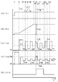
図1は、本発明の実施の形態1に係るパルスアーク溶接の出力制御方法を説明するためのタイミングチャートである。同図(A)は溶接開始信号Stの時間変化を示し、同図(B)は送給速度Fwの時間変化を示し、同図(C)は溶接電流Iwの時間変化を示し、同図(D)は溶接電圧Vwの時間変化を示し、同図(E)は修正期間信号Stkの時間変化を示す。同図において、上述した図5と同一の動作についての説明は繰り返さない。以下、同図を参照して説明する。 FIG. 1 is a timing chart for explaining an output control method of pulse arc welding according to a first embodiment of the present invention. The figure (A) shows the time change of welding start signal St, the figure (B) shows the time change of feed speed Fw, the figure (C) shows the time change of welding current Iw, the figure ( D) shows the time change of welding voltage Vw, and the figure (E) shows the time change of correction period signal Stk. In the figure, the description of the same operation as that of FIG. 5 described above will not be repeated. This will be described below with reference to the same figure.
時刻t1において、同図(A)に示すように、溶接開始信号StがHighレベル(溶接開始)に変化すると、溶接電源が起動されて、同図(B)に示すように、溶接ワイヤ1は予め定めたスローダウン速度による送給が開始され、同図(D)に示すように、無負荷電圧が溶接ワイヤ1と母材2との間に印加される。スローダウン速度は、1m/min程度の遅い速度に設定される。
When the welding start signal St changes to High level (welding start) at time t1 as shown in (A) in the figure, the welding power source is activated, and as shown in (B) in FIG. The feed at a predetermined slow down speed is started, and a no-load voltage is applied between the
時刻t2において、溶接ワイヤ1の先端が母材2と接触すると、短い短絡の後にアーク3が発生する。これに応動して、同図(C)に示すように、時刻t2〜t3の予め定めたホットスタート期間Th中は予め定めた大電流値のホットスタート電流Ih(500A程度)が通電する。同図(D)に示すように、溶接電圧Vwは、時刻t2から短い短絡の間は数Vの短絡電圧値に急減し、アーク3が発生すると時刻t3まで数十Vのアーク電圧値に増加する。時刻t2に溶接電流Iwが通電を開始すると、同図(B)に示すように、送給速度Fwは傾斜を有して加速されて、時刻t7に予め定めた定常送給速度Fwcに収束する。同図(E)に示すように、修正期間信号StkはLowレベルであり、後述するように、時刻t9〜t12の期間中はHighレベルとなる。修正期間信号StkがHighレベルの期間が修正期間Tkとなる。
When the tip of
時刻t3にホットスタート期間Thが終了すると、時刻t3〜t4の期間中は、同図(C)に示すように、予め定めた定常ベース電流Ibcが通電し、同図(D)に示すように、アーク長に比例した定常ベース電圧Vbcが印加する。 When the hot start period Th ends at time t3, during a period from time t3 to t4, as shown in FIG. 6C, a predetermined steady base current Ibc is supplied, and as shown in FIG. , A steady base voltage Vbc proportional to the arc length is applied.
時刻t4〜t5の予め定めたピーク期間Tp中は、同図(C)に示すように、予め定めた定常ピーク電流Ipcが通電し、同図(D)に示すように、アーク長に比例した定常ピーク電圧Vpcが印加する。この時点ではアーク長が急速に長くなる現象は発生していないので、定常ピーク電圧Vpcは、破線で示す基準電圧値Vth未満となっている。基準電圧値Vthは、アーク長が適正範囲よりも長くなったときのピーク電圧値に基づいて実験によって予め設定される。すなわち、ピーク電圧値が基準電圧値Vth以上になったときはアーク長が適正範囲よりも長くなったときであり、アーク長が急速に長くなる現象が発生したときであると判別することができる。時刻t5〜t6のベース期間Tb中は、同図(C)に示すように、上記の定常ベース電流Ibcが通電し、同図(D)に示すように、上記の定常ベース電圧Vbcが印加する。上述したように、時刻t4〜t6のパルス周期Tf中の溶接電圧Vwの平均値が予め定めた溶接電圧設定信号Vrと等しくなるようにパルス周期Tf(ベース期間Tb)がフィードバック制御(周波数変調制御)される。 During a predetermined peak period Tp from time t4 to t5, as shown in FIG. 6C, a predetermined steady-state peak current Ipc is supplied, and as shown in FIG. 6D, it is proportional to the arc length. A steady-state peak voltage Vpc is applied. At this point of time, the phenomenon that the arc length rapidly increases does not occur, so the steady-state peak voltage Vpc is less than the reference voltage value Vth indicated by the broken line. The reference voltage value Vth is preset by an experiment based on the peak voltage value when the arc length is longer than the appropriate range. That is, when the peak voltage value becomes equal to or higher than the reference voltage value Vth, it can be determined that the arc length becomes longer than the appropriate range and the phenomenon that the arc length becomes rapidly longer occurs. . During the base period Tb from time t5 to t6, the steady base current Ibc is energized as shown in FIG. 7C, and the steady base voltage Vbc is applied as shown in FIG. . As described above, the pulse period Tf (base period Tb) is feedback controlled (frequency modulation control) so that the average value of the welding voltage Vw in the pulse period Tf from time t4 to t6 is equal to the predetermined welding voltage setting signal Vr. ).
時刻t6〜t8のパルス周期Tfの動作は、時刻t4〜t6のパルス周期Tfの動作と同様である。時刻t6〜t8のパルス周期Tf中の時刻t7において、同図(B)に示すように、送給速度Fwは定常送給速度Fwcに収束する。時刻t2〜t7の送給速度Fwの傾斜期間は50ms程度である。同図では、この傾斜期間中に2周期分の波形が描画されているが、実際には10周期程度となる。 The operation of the pulse period Tf from time t6 to t8 is similar to the operation of the pulse period Tf from time t4 to t6. At time t7 during the pulse cycle Tf from time t6 to t8, as shown in FIG. 7B, the feed speed Fw converges to the steady feed speed Fwc. The inclination period of the feed speed Fw from time t2 to t7 is about 50 ms. In the same figure, a waveform for two cycles is drawn during this inclination period, but in actuality it will be around 10 cycles.
時刻t8からのピーク期間Tp中にアーク長が急速に長くなる現象が発生したために、同図(D)に示すように、ピーク電圧が立ち上がった時刻t9において破線で示す基準電圧値Vthを超えているので、同図(E)に示すように、修正期間信号Stkは時刻t9にHighレベルに変化する。この修正期間信号Stkは、時刻t9から所定期間後の時刻t12においてLowレベルに戻る。修正期間信号StkがHighレベルであるので、同図(C)に示すように、予め定めた修正ピーク電流Ipkが通電し、同図(D)に示すように、基準電圧値Vth以上の修正ピーク電圧Vpkが印加する。同様に、時刻t10からのベース期間Tb中は、修正期間信号StkがHighレベルであるので、同図(C)に示すように、予め定めた修正ベース電流Ibkが通電し、同図(D)に示すように、アーク長が長くなっているので定常ベース電圧Vbcよりも大きな値の修正ベース電圧Vbkが印加する。上述したように、時刻t8〜t11のパルス周期Tf中の溶接電圧Vwの平均値が上記の溶接電圧設定信号Vrと等しくなるようにパルス周期Tf(ベース期間Tb)がフィードバック制御(周波数変調制御)される。 Since a phenomenon in which the arc length rapidly increases during peak period Tp from time t8 occurs, as shown in FIG. 7D, it exceeds the reference voltage value Vth shown by the broken line at time t9 when the peak voltage rises. Therefore, as shown in FIG. 6E, the correction period signal Stk changes to the high level at time t9. The correction period signal Stk returns to the low level at time t12 which is a predetermined period after time t9. Since the correction period signal Stk is at the high level, as shown in FIG. 7C, a predetermined correction peak current Ipk is applied, and as shown in FIG. 6D, the correction peak higher than the reference voltage value Vth. A voltage Vpk is applied. Similarly, during the base period Tb from time t10, since the correction period signal Stk is at the high level, a predetermined correction base current Ibk is supplied as shown in FIG. As shown in FIG. 5, since the arc length is long, the corrected base voltage Vbk having a value larger than the steady base voltage Vbc is applied. As described above, the pulse period Tf (base period Tb) is feedback controlled (frequency modulation control) so that the average value of the welding voltage Vw in the pulse period Tf from time t8 to t11 becomes equal to the welding voltage setting signal Vr. Be done.
時刻t11〜t13のパルス周期Tfの動作は、時刻t8〜t11のパルス周期Tfの動作と同様である。時刻t11〜t13のパルス周期Tf中のベース期間Tb中の時刻t12において、同図(E)に示すように、所定期間が終了したために修正期間信号StkはLowレベルに戻る。時刻t9〜t12の修正期間Tkは50〜300ms程度に設定される。同図では、この修正期間Tk中に2周期分の波形が描画されているが、実際には10〜60周期程度となる。 The operation of the pulse cycle Tf from time t11 to t13 is similar to the operation of the pulse cycle Tf from time t8 to t11. At time t12 in the base period Tb in the pulse period Tf from time t11 to t13, as shown in FIG. 7E, the correction period signal Stk returns to the low level because the predetermined period ends. The correction period Tk of time t9 to t12 is set to about 50 to 300 ms. In the same figure, although the waveform for two cycles is drawn in this correction period Tk, it becomes about 10 to 60 cycles in fact.
時刻t13〜t15のパルス周期Tfからは同図(E)に示す修正期間信号StkがLowレベルであるので、上述した時刻t4〜t8の定常溶接期間中と同様の動作となる。時刻t13〜t14の上記のピーク期間Tp中は、同図(C)に示すように、上記の定常ピーク電流Ipcが通電する。アーク長は修正期間Tkの電流制御によって適正範囲に復帰しているので、同図(D)に示すように、基準電圧値Vth未満の定常ピーク電圧Vpcが印加する。時刻t14〜t15のベース期間Tb中は、同図(C)に示すように、上記の定常ベース電流Ibcが通電し、同図(D)に示すように、アーク長に比例した定常ベース電圧Vbcが印加する。これ以降は、本周期の動作を繰り返すことになる。 Since the correction period signal Stk shown in FIG. 5E is at the low level from the pulse period Tf of time t13 to t15, the same operation as in the steady welding period of time t4 to t8 described above is performed. During the above peak period Tp from time t13 to t14, the steady peak current Ipc flows as shown in FIG. Since the arc length is restored to the appropriate range by current control in the correction period Tk, a steady-state peak voltage Vpc less than the reference voltage value Vth is applied, as shown in FIG. During the base period Tb from time t14 to t15, as shown in FIG. 6C, the above-mentioned steady base current Ibc is supplied, and as shown in FIG. 14D, the steady base voltage Vbc proportional to the arc length. Apply. After this, the operation of this cycle will be repeated.
上記の修正ピーク電流Ipkは、上記の定常ピーク電流Ipcの値を予め定めた減少値Δdだけ減少させた値に設定される。上記の修正ベース電流Ibkは、上記の定常ベース電流Ibcの値を予め定めた増加値Δuだけ増加させた値に設定される。定常ピーク電流Ipcは、臨界値以上の値であり、1パルス周期1溶滴移行状態となる範囲に設定される。定常ベース電流Ibcは、臨界値未満の値であり、ベース期間Tb中に溶滴が形成されない範囲に設定される。修正ピーク電流Ipkは、臨界値以上の値であるが、減少値Δdだけ減少させているので複数パルス周期1溶滴移行状態となることが多い。修正ベース電流Ibkは、臨界値未満の値に設定されるが、増加値Δuだけ増加されているので、ベース期間Tb中に溶滴が少し形成されることになる場合が多い。
The corrected peak current Ipk is set to a value obtained by reducing the value of the steady-state peak current Ipc by a predetermined decrease value Δd. The corrected base current Ibk is set to a value obtained by increasing the value of the steady base current Ibc by a predetermined increase value Δu. The steady-state peak current Ipc is a value equal to or greater than the critical value, and is set to a range in which one
アークスタート後の過渡期間中にアーク長が急速に長くなる現象が発生したときのアーク状態を、高速度カメラを使用して観察した。アーク長が通常状態のときは、ワイヤ突出し部の下端に形成されている溶滴からアーク3が発生している。アーク長が急速に長くなる現象は、ワイヤ突出し部の中間位置で溶断し、その溶断部からアーク3が発生した状態であることが判別した。ワイヤ突出し部の中間位置で溶断する理由は、溶断位置のワイヤ1に損傷があり、そのために異常加熱されて溶断したことが判別した。溶接ワイヤ1に損傷が生じる理由は、前回の溶接終了時に送給速度Fwが減速して送給が停止するときに、給電チップの内面と溶接ワイヤ1とが接触して給電する部分で摩擦、アーキング等によって溶接ワイヤ1に損傷が生じる場合があるためである。また、アークスタート時に送給速度Fwが加速されるときも、同様にして溶接ワイヤ1に損傷が生じる場合があるためである。そして、給電チップ内で損傷した溶接ワイヤ1の個所が、ワイヤ突出し部の中間位置まで送給されるためには、アークスタート後に100〜500ms程度の時間がかかることになる。このために、アーク長が急速に長くなる現象は、アークスタート後の100〜500ms程度の範囲に生じる傾向がある。但し、溶接ワイヤ1が損傷を受けても、溶接ワイヤ1の単位長さ当たりの抵抗値(以下、単位長抵抗値という)が小さい場合には、異常加熱は生じにくいために、アーク長が急速に長くなる現象は発生しにくくなる。定常溶接期間中に溶接ワイヤ1が損傷を受けた場合には、アーク長が急速に長くなる現象が発生する場合がある。定常溶接期間中に、送給速度Fwの加減速が繰り返される場合には、現象の発生頻度が高くなる。
The arc condition was observed using a high-speed camera when a phenomenon in which the arc length increased rapidly during the transition period after the arc start occurred. When the arc length is in the normal state, the
したがって、アーク長が急速に長くなる現象が発生するのを抑制するためには、給電チップ内での溶接ワイヤ1への損傷を防止するか、又は、異常加熱を防止するかになる。溶接ワイヤ1への損傷を防止することは難しいので、異常加熱を防止する対策を行うことにする。異常加熱は、溶接ワイヤ1の損傷部に大電流値のピーク電流が通電することによって発生する。このために、アーク長が急速に長くなる現象の発生をピーク電圧値が基準電圧値Vth以上になったことによって早期に判別し、判別時点からの修正期間Tk中は、定常ピーク電流Ipcを減少値Δdだけ減少させた修正ピーク電流Ipkを通電することによって異常加熱を防止する。但し、修正ピーク電流Ipkは、定常ピーク電流Ipcに近い値であるほど、すなわち、減少値Δdが小さな値であるほど、溶滴移行状態は良好になる。換言すれば、減少値Δdが大きくなると、溶滴移行状態が少し悪くなるので、スパッタが増加することになる。したがって、減少値Δdは、アーク長が急速に長くなる現象が進行しない範囲で、最小値に設定することが望ましい。異常加熱は溶接ワイヤの単位長抵抗値が大きいほど発生しやすくなる。このために、減少値Δdの適正値は、溶接ワイヤ1の単位長抵抗値に応じて変化させることが望ましい。この関係については、図2で後述する。
Therefore, in order to suppress the occurrence of the phenomenon in which the arc length is rapidly increased, it is possible to prevent damage to the
修正ピーク電流Ipkが定常ピーク電流Ipcよりも小さい値であるために、修正期間Tk中のパルス周期Tfの平均値は定常溶接期間中のパルス周期Tfの平均値よりも長くなる。パルス周期Tfが長くなると、溶接状態がやや不安定になる。パルス周期Tfが変化する理由は、上述した周波数変調制御のためである。修正期間Tk中のパルス周期Tfの平均値を定常溶接期間中のパルス周期Tfの平均値と等しくするためには、修正ベース電流Ibkを定常ベース電流Ibcよりも大きくすれば良い。このために、修正ベース電流Ibkは、定常ベース電流Ibcを増加値Δuだけ増加させた値に設定される。したがって、増加値Δuは、修正ピーク電流Ipkが設定された後に、修正期間Tk中のパルス周期Tfの平均値と定常溶接期間中のパルス周期Tfの平均値との差が所定値未満になるように設定される。所定値は、10%程度である。 Since the corrected peak current Ipk is smaller than the steady-state peak current Ipc, the average value of the pulse period Tf during the correction period Tk is longer than the mean value of the pulse period Tf during the steady-state welding period. As the pulse period Tf becomes longer, the welding state becomes somewhat unstable. The pulse period Tf changes because of the above-described frequency modulation control. In order to make the average value of the pulse period Tf in the correction period Tk equal to the average value of the pulse period Tf in the steady welding period, the corrected base current Ibk should be larger than the steady base current Ibc. For this purpose, the corrected base current Ibk is set to a value obtained by increasing the steady base current Ibc by the increase value Δu. Therefore, the increase value Δu is set such that the difference between the average value of the pulse period Tf during the correction period Tk and the average value of the pulse period Tf during the steady welding period is less than a predetermined value after the correction peak current Ipk is set. Set to The predetermined value is about 10%.
アーク長制御がパルス幅変調制御である場合には、パルス周期Tfは固定値となり、ピーク期間(パルス幅)Tpがフィードバック制御される。このために、修正期間Tkと定常溶接期間とでピーク期間Tpの平均値の差が所定値未満になるように、修正ベース電流Ibk(増加値Δu)を設定すれば良い。 When the arc length control is pulse width modulation control, the pulse period Tf has a fixed value, and the peak period (pulse width) Tp is feedback controlled. For this purpose, the correction base current Ibk (increase value Δu) may be set so that the difference between the average values of the peak periods Tp between the correction period Tk and the steady welding period is less than a predetermined value.
図2は、縦軸に示す減少値Δd[A]と横軸に示す溶接ワイヤの単位長抵抗値Rw[mΩ/mm]との関係を示す図である。 FIG. 2 is a view showing the relationship between the decrease value Δd [A] shown on the vertical axis and the unit length resistance value Rw [mΩ / mm] of the welding wire shown on the horizontal axis.
同図に示すように、Rw<0.03の範囲では、Δd=0となっている。これは、溶接ワイヤの単位長抵抗値Rwが小さいために、溶接ワイヤに損傷が生じても異常加熱にならないためである。溶接ワイヤの材質がアルミニウムである場合には、この範囲に属する。 As shown in the figure, in the range of Rw <0.03, Δd = 0. This is because, since the unit length resistance value Rw of the welding wire is small, abnormal heating does not occur even if the welding wire is damaged. When the material of the welding wire is aluminum, it belongs to this range.
Rw≧0.03の範囲では、右肩上がりの直線となっている。すなわち、単位長抵抗値Rwが大きくなるほど、減少値Δdも大きくなる。直径1.2mmの軟鋼ソリッドワイヤの場合、Rw=0.09となり、Δd=10Aとなる。直径0.9mmの軟鋼ソリッドワイヤの場合、Rw=0.16となり、Δd=20Aとなる。直径1.2mmのステンレス鋼ソリッドワイヤの場合、Rw=0.65となり、Δd=80Aとなる。直径1.2mmのステンレス鋼のメタル系コアートワイヤの場合、Rw=0.85となり、Δd=100Aとなる。 In the range of Rw ≧ 0.03, it is a straight line rising to the right. That is, as the unit length resistance value Rw increases, the decrease value Δd also increases. In the case of a mild steel solid wire with a diameter of 1.2 mm, Rw = 0.09 and Δd = 10A. In the case of a soft steel solid wire with a diameter of 0.9 mm, Rw = 0.16, and Δd = 20A. In the case of a stainless steel solid wire with a diameter of 1.2 mm, Rw = 0.65, and Δd = 80A. In the case of a metal-based coret wire of stainless steel having a diameter of 1.2 mm, Rw = 0.85 and Δd = 100A.
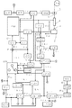
図3は、図1で上述した本発明の実施の形態1に係るパルスアーク溶接の出力制御方法を実施するための溶接電源のブロック図である。以下、同図を参照して各ブロックについて説明する。 FIG. 3 is a block diagram of a welding power source for implementing the power control method of pulse arc welding according to the first embodiment of the present invention described above with reference to FIG. Each block will be described below with reference to the figure.
電源主回路PMは、3相200V等の商用電源(図示は省略)を入力として、後述する駆動信号Dvに従ってインバータ制御による出力制御を行い、溶接電流Iw及び溶接電圧Vwを出力する。この電源主回路PMは、図示は省略するが、商用電源を整流する1次整流器、整流された直流を平滑するコンデンサ、平滑された直流を上記の駆動信号Dvに従って高周波交流に変換するインバータ回路、高周波交流をアーク溶接に適した電圧値に降圧する高周波変圧器、降圧された高周波交流を整流する2次整流器、整流された直流を平滑するリアクトルを備えている。 Power supply main circuit PM receives a commercial power supply (not shown) such as three-phase 200 V, performs output control by inverter control according to a drive signal Dv described later, and outputs welding current Iw and welding voltage Vw. Although not shown, the power supply main circuit PM is a primary rectifier for rectifying a commercial power supply, a capacitor for smoothing rectified DC, and an inverter circuit for converting the smoothed DC into high frequency AC according to the drive signal Dv. The high frequency transformer which steps down high frequency alternating current to a voltage value suitable for arc welding, the secondary rectifier which rectifies the stepped down high frequency alternating current, and the reactor which smoothes the rectified direct current are provided.
溶接ワイヤ1は、ワイヤリール1aに巻かれている。溶接ワイヤ1は、ワイヤ送給モータWMに結合された送給ロール5の回転によって溶接トーチ4内を送給されて、母材2との間にアーク3が発生して溶接が行われる。アーク3中を溶接電流Iwが通電し、溶接トーチ4内の給電チッップ(図示は省略)と母材2との間に溶接電圧Vwが印加する。
The
溶接電圧検出回路VDは、上記の溶接電圧Vwを検出して溶接電圧検出信号Vdを出力する。溶接電圧平均値算出回路VAVは、この溶接電圧検出信号Vdを入力として、ローパスフィルタに通すことによって平均化して、溶接電圧平均値信号Vavを出力する。溶接電圧設定回路VRは、予め定めた溶接電圧設定信号Vrを出力する。電圧誤差増幅回路EVは、この溶接電圧設定信号Vrと上記の溶接電圧平均値信号Vavとの誤差を増幅して、電圧誤差増幅信号Evを出力する。 The welding voltage detection circuit VD detects the welding voltage Vw and outputs a welding voltage detection signal Vd. Welding voltage average value calculation circuit VAV takes this welding voltage detection signal Vd as an input, passes it through a low pass filter, and averages it to output welding voltage average value signal Vav. Welding voltage setting circuit VR outputs a predetermined welding voltage setting signal Vr. The voltage error amplification circuit EV amplifies an error between the welding voltage setting signal Vr and the welding voltage average value signal Vav to output a voltage error amplification signal Ev.
電圧・周波数変換回路VFは、上記の電圧誤差増幅信号Evを入力として、この電圧誤差増幅信号Evの値に応じた周波数を有するパルス周期信号Tfを出力する。このパルス周期信号Tfは、パルス周期ごとに短時間Highレベルになる信号である。 The voltage / frequency conversion circuit VF receives the voltage error amplification signal Ev as an input, and outputs a pulse cycle signal Tf having a frequency corresponding to the value of the voltage error amplification signal Ev. The pulse cycle signal Tf is a signal that goes high for a short time every pulse cycle.
ピーク期間設定回路TPRは、予め定めたピーク期間設定信号Tprを出力する。タイマ回路TMは、上記のピーク期間設定信号Tpr及び上記のパルス周期信号Tfを入力として、パルス周期信号TfがHighレベルに変化するごとにピーク期間設定信号Tprによって定まる期間だけHighレベルになるタイマ信号Tmを出力する。したがって、このタイマ信号TmがHighレベルのときはピーク期間になり、Lowレベルのときはベース期間になる。 The peak period setting circuit TPR outputs a predetermined peak period setting signal Tpr. The timer circuit TM receives the above peak period setting signal Tpr and the above pulse cycle signal Tf as input, and whenever the pulse cycle signal Tf changes to high level, a timer signal which becomes high level only during a period determined by the peak period setting signal Tpr. Output Tm. Therefore, when the timer signal Tm is at the high level, it is a peak period, and when it is at the low level, it is a base period.
溶接開始回路STは、溶接電源を起動するときにHighレベルとなる溶接開始信号Stを出力する。この溶接開始回路STは、溶接トーチ4の起動スイッチ、溶接工程を制御するPLC、ロボット制御装置等が相当する。
The welding start circuit ST outputs a welding start signal St which becomes High level when the welding power source is started. The welding start circuit ST corresponds to a start switch of the
溶接電流検出回路IDは、上記の溶接電流Iwを検出して溶接電流検出信号Idを出力する。電流通電判別回路CDは、上記の溶接電流検出信号Idを入力として、この値がしきい値(10A程度)以上のときは溶接電流Iwが通電していると判別してHighレベルとなる電流通電判別信号Cdを出力する。 The welding current detection circuit ID detects the above-mentioned welding current Iw and outputs a welding current detection signal Id. The current conduction determination circuit CD receives the above-described welding current detection signal Id, and when the value is equal to or more than a threshold (about 10 A), it determines that the welding current Iw is flowing and conducts current at high level. The discrimination signal Cd is output.
ホットスタート期間回路STHは、上記の電流通電判別信号Cdを入力として、電流通電判別信号CdがHighレベルに変化した時点から予め定めたホットスタート期間Th中はHighレベルとなるホットスタート期間信号Sthを出力する。ホットスタート電流設定回路IHRは、予め定めたホットスタート電流設定信号Ihrを出力する。 The hot start period circuit STH receives the current conduction determination signal Cd as an input and starts the hot start period signal Sth which becomes high level during a predetermined hot start period Th from the time when the current conduction determination signal Cd changes to high level. Output. The hot start current setting circuit IHR outputs a predetermined hot start current setting signal Ihr.
溶接ワイヤ選択回路WSは、使用する溶接ワイヤの材質及びその直径の組み合わせを選択して、溶接ワイヤ選択信号Wsを出力する。例えば、直径1.2mmの軟鋼ソリッドワイヤを選択するとWs=1となり、直径0.9mmの軟鋼ソリッドワイヤを選択するとWs=2となり、直径1.2mmのステンレス鋼メタル系コアードワイヤを選択するとWs=3となる。 The welding wire selection circuit WS selects the combination of the material and diameter of the welding wire to be used, and outputs a welding wire selection signal Ws. For example, when selecting a mild steel solid wire with a diameter of 1.2 mm, Ws = 1, when selecting a soft steel solid wire with a diameter of 0.9 mm, Ws = 2, and when selecting a stainless steel metal cored wire with a diameter of 1.2 mm, Ws = 3 It becomes.
単位長抵抗値設定回路RWRは、上記の溶接ワイヤ選択信号Wsを入力として、溶接ワイヤ選択信号Wsに対応する溶接ワイヤの単位長抵抗値を内蔵されているデータベースから読みだして、単位長抵抗値設定信号Rwrを出力する。 Unit length resistance value setting circuit RWR receives the above-mentioned welding wire selection signal Ws, reads the unit length resistance value of the welding wire corresponding to welding wire selection signal Ws from the built-in database, and performs the unit length resistance value. The setting signal Rwr is output.
減少値設定回路ΔDRは、上記の単位長抵抗値設定信号Rwrを入力として、図2で上述した関係式に基づいて算出された減少値設定信号Δdrを出力する。 The reduction value setting circuit ΔDR receives the unit length resistance value setting signal Rwr as described above, and outputs a reduction value setting signal Δdr calculated based on the relational expression described above with reference to FIG.
溶接電流平均値設定回路IRは、予め定めた溶接電流平均値設定信号Irを出力する。 Welding current average value setting circuit IR outputs a predetermined welding current average value setting signal Ir.
定常ピーク電流設定回路IPCRは、予め定めた定常ピーク電流設定信号Ipcrを出力する。定常ベース電流設定回路IBCRは、予め定めた定常ベース電流設定信号Ibcrを出力する。 The steady-state peak current setting circuit IPCR outputs a predetermined steady-state peak current setting signal Ipcr. Steady-state base current setting circuit IBCR outputs a predetermined steady-state base current setting signal Ibcr.
修正ピーク電流設定回路IPKRは、上記の定常ピーク電流設定信号Ipcr及び上記の減少値設定信号Δdrを入力として、定常ピーク電流設定信号Ipcrから減少値設定信号Δdrを減算して、修正ピーク電流設定信号Ipkrとして出力する。 The corrected peak current setting circuit IPKR receives the steady peak current setting signal Ipcr and the decrement value setting signal Δdr as described above, subtracts the decrement value setting signal Δdr from the steady peak current setting signal Ipcr, and corrects the corrected peak current setting signal. Output as Ipkr.
定常溶接期間パルス周期算出回路TFCは、上記の溶接電流平均値設定信号Ir、上記のピーク期間設定信号Tpr、上記の定常ピーク電流設定信号Ipcr及び上記の定常ベース電流設定信号Ibcrを入力として、Tfc=(Tpr・(Ipcr−Ibcr))/(Ir−Ibcr)を算出して、定常溶接期間パルス周期信号Tfcを出力する。 The steady welding period pulse period calculation circuit TFC receives the welding current average value setting signal Ir, the peak period setting signal Tpr, the steady peak current setting signal Ipcr, and the steady base current setting signal Ibcr as inputs. = (Tpr · (Ipcr-Ibcr)) / (Ir-Ibcr) is calculated, and a steady welding period pulse period signal Tfc is output.
修正ベース電流設定回路IBKRは、上記の溶接電流平均値設定信号Ir、上記の定常溶接期間パルス周期信号Tfc、上記のピーク期間設定信号Tpr及び上記の修正ピーク電流設定信号Ipkrを入力として、Ibkr=(Tfc・Ir−Tpr・Ipkr)/(Tfc−Tpr)を算出して、修正ベース電流設定信号Ibkrとして出力する。 The correction base current setting circuit IBKR receives the welding current average value setting signal Ir, the steady welding period pulse period signal Tfc, the peak period setting signal Tpr, and the corrected peak current setting signal Ipkr as inputs, Ibkr = (Tfc.Ir-Tpr.Ipkr) / (Tfc-Tpr) is calculated and output as the corrected base current setting signal Ibkr.
修正期間回路STKは、上記の溶接電圧検出信号Vd、上記のホットスタート期間信号Sth及び上記のタイマ信号Tmを入力として、ホットスタート期間信号SthがHighレベルからLowレベルに変化した後に(ホットスタート期間Thの終了後に)、タイマ信号TmがHighレベル(ピーク期間)であるときの溶接電圧検出信号Vdの値が予め定めた基準電圧値Vth以上になったときはHighレベルにセットされ、それから所定期間後にLowレベルにリセットされる修正期間信号Stkを出力する。 The correction period circuit STK receives the welding voltage detection signal Vd described above, the hot start period signal Sth described above and the timer signal Tm described above, and after the hot start period signal Sth changes from high level to low level (hot start period After the end of Th), when the value of welding voltage detection signal Vd when timer signal Tm is at High level (peak period) becomes equal to or higher than a predetermined reference voltage value Vth, it is set to High level, and then predetermined period The correction period signal Stk, which is later reset to the low level, is output.
ピーク電流設定回路IPRは、上記の修正期間信号Stk、上記の修正ピーク電流設定信号Ipkr及び上記の定常ピーク電流設定信号Ipcrを入力として、修正期間信号StkがHighレベル(修正期間)のときは修正ピーク電流設定信号Ipkrをピーク電流設定信号Iprとして出力し、Stk=Lowレベル(定常溶接期間)のときは定常ピーク電流設定信号Ipcrをピーク電流設定信号Iprとして出力する。 The peak current setting circuit IPR receives the above correction period signal Stk, the above correction peak current setting signal Ipkr and the above steady peak current setting signal Ipcr as input, and corrects it when the correction period signal Stk is High level (correction period) The peak current setting signal Ipkr is output as a peak current setting signal Ipr, and when Stk = Low level (stationary welding period), the steady peak current setting signal Ipcr is output as a peak current setting signal Ipr.
ベース電流設定回路IBRは、上記の修正期間信号Stk、上記の修正ベース電流設定信号Ibkr及び上記の定常ベース電流設定信号Ibcrを入力として、修正期間信号StkがHighレベル(修正期間)のときは修正ベース電流設定信号Ibkrをベース電流設定信号Ibrとして出力し、Stk=Lowレベル(定常溶接期間)のときは定常ベース電流設定信号Ibcrをベース電流設定信号Ibrとして出力する。 The base current setting circuit IBR receives the above correction period signal Stk, the above correction base current setting signal Ibkr and the above steady base current setting signal Ibcr as input, and corrects it when the correction period signal Stk is High level (correction period) The base current setting signal Ibkr is output as the base current setting signal Ibr, and when Stk = Low level (stationary welding period), the steady base current setting signal Ibcr is output as the base current setting signal Ibr.
切換回路SWは、上記のホットスタート期間信号Sth、上記のタイマ信号Tm、上記のホットスタート電流設定信号Ihr、上記のピーク電流設定信号Ipr及び上記のベース電流設定信号Ibrを入力として、ホットスタート期間信号SthがHighレベルのときはホットスタート電流設定信号Ihrを電流制御設定信号Icrとして出力し、ホットスタート期間信号SthがLowレベルであり、かつ、タイマ信号TmがHighレベルのときはピーク電流設定信号Iprを電流制御設定信号Icrとして出力し、ホットスタート期間信号SthがLowレベルであり、かつ、タイマ信号TmがLowレベルのときはベース電流設定信号Ibrを電流制御設定信号Icrとして出力する。 The switching circuit SW receives the hot start period signal Sth, the timer signal Tm, the hot start current setting signal Ihr, the peak current setting signal Ipr and the base current setting signal Ibr as input, and performs a hot start period. When the signal Sth is high level, the hot start current setting signal Ihr is output as the current control setting signal Icr, and when the hot start period signal Sth is low level and the timer signal Tm is high level, the peak current setting signal Ipr is output as the current control setting signal Icr, and when the hot start period signal Sth is at the low level and the timer signal Tm is at the low level, the base current setting signal Ibr is output as the current control setting signal Icr.
電流誤差増幅回路EIは、上記の電流制御設定信号Icrと上記の溶接電流検出信号Idとの誤差を増幅して、電流誤差増幅信号Eiを出力する。駆動回路DVは、この電流誤差増幅信号Ei及び上記の溶接開始信号Stを入力として、溶接開始信号StがHighレベルのときは、PWM制御を行い、上記の電源主回路PMのインバータ回路を駆動するための駆動信号Dvを出力する。 The current error amplification circuit EI amplifies an error between the current control setting signal Icr and the welding current detection signal Id, and outputs a current error amplification signal Ei. Drive circuit DV receives this current error amplification signal Ei and the above-mentioned welding start signal St, and when the welding start signal St is at a high level, performs PWM control to drive the inverter circuit of the above-mentioned power supply main circuit PM. And outputs a drive signal Dv.
送給速度設定回路FRは、上記の溶接電流平均値設定信号Irを入力として、予め内蔵されている溶接電流平均値と送給速度との関係式によって溶接電流平均値設定信号Irの値に対応した送給速度設定信号Frを算出して出力する。 Feed speed setting circuit FR receives the above-mentioned welding current average value setting signal Ir, and corresponds to the value of welding current average value setting signal Ir according to the relation between the welding current average value and the feeding speed built in advance. The feed speed setting signal Fr is calculated and output.
送給制御回路FCは、上記の送給速度設定信号Fr、上記の溶接開始信号St及び上記の電流通電判別信号Cdを入力として、溶接開始信号StがHighレベルになると予め定めたスローダウン速度で溶接ワイヤ1を送給するための送給制御信号Fcを出力し、その後に電流通電判別信号CdがHighレベルに変化すると予め定めた傾斜で加速して送給速度設定信号Frによって定まる送給速度Fwで溶接ワイヤ1を送給するための送給制御信号Fcを上記のワイヤ送給モータWMに出力する。
The feed control circuit FC receives the feed speed setting signal Fr, the welding start signal St, and the current conduction discrimination signal Cd as inputs, and at a predetermined slow-down speed when the welding start signal St becomes High level. A feed control signal Fc for feeding the
同図は、アーク長制御の方式が周波数変調制御の場合である。パルス幅変調制御の場合は、上記のパルス周期信号Tfを所定値に設定し、上記の電圧誤差増幅信号Evに基づいて上記のピーク期間設定信号Tprをフィードバック制御するようにすれば良い。このときに、上記の修正ベース電流設定信号Ibkrは、修正期間中のピーク期間の平均値と定常溶接期間中のピーク期間の平均値との差が所定値未満になるように設定すれば良い。 This figure shows the case where the method of arc length control is frequency modulation control. In the case of pulse width modulation control, the pulse cycle signal Tf may be set to a predetermined value, and the peak period setting signal Tpr may be feedback controlled based on the voltage error amplification signal Ev. At this time, the corrected base current setting signal Ibkr may be set such that the difference between the average value of peak periods in the correction period and the average value of peak periods in the steady welding period is less than a predetermined value.
上述した実施の形態1によれば、ピーク期間中の溶接電圧であるピーク電圧が予め定めた基準電圧値以上になったときは、ピーク電流を予め定めた減少値だけ減少させ、かつ、ベース電流を予め定めた増加値だけ増加させる。減少値は、溶接ワイヤの単位長抵抗値に基づいて設定される。アーク長制御が周波数変調制御であるときは、増加値は、修正期間中のパルス周期の平均値と定常溶接期間中のパルス周期の平均値との差が所定値未満になるように設定される。アーク長制御がパルス幅変調制御であるときは、増加値は、修正期間中のピーク期間の平均値と定常溶接期間中のピーク期間の平均値との差が所定値未満になるように設定される。修正期間は、所定期間に設定される。これにより、本実施の形態では、アーク長が急速に長くなる現象が発生しても、早期にピーク電流値が減少するので、異常加熱状態を抑制することができる。このために、本実施の形態では、アーク長が急速に長くなる現象の進行を抑制し、アーク長を迅速に適正状態に復帰させることができる。さらに、本実施の形態では、ピーク電流を減少させている期間(修正期間)中とピーク電流を減少させていない期間(定常溶接期間)中とで、パルス周期又はピーク期間の平均値が所定値未満の差となるので、両期間中の溶接状態を良好に保つことができる。 According to the first embodiment described above, when the peak voltage which is the welding voltage in the peak period becomes equal to or higher than a predetermined reference voltage value, the peak current is decreased by a predetermined decrease value, and the base current Is increased by a predetermined increase value. The reduction value is set based on the unit length resistance value of the welding wire. When the arc length control is frequency modulation control, the increase value is set such that the difference between the average value of the pulse periods during the correction period and the average value of the pulse periods during the steady welding period is less than a predetermined value. . When the arc length control is pulse width modulation control, the increase value is set such that the difference between the average value of peak periods in the correction period and the average value of peak periods in the steady welding period is less than a predetermined value. Ru. The correction period is set to a predetermined period. As a result, in the present embodiment, even if the phenomenon in which the arc length becomes long rapidly occurs, the peak current value decreases early, so that the abnormal heating state can be suppressed. For this reason, in the present embodiment, it is possible to suppress the progress of the phenomenon in which the arc length is rapidly increased, and to quickly return the arc length to the appropriate state. Furthermore, in the present embodiment, the average value of the pulse period or peak period is a predetermined value during the period during which the peak current is reduced (correction period) and during the period when the peak current is not decreased (steady welding period). Since the difference is less than, it is possible to keep the welding condition well during both periods.
[実施の形態2]
実施の形態2の発明は、修正期間Tkはピーク電圧が基準電圧値未満になるまでの期間に設定されるものである。
Second Embodiment
In the invention of the second embodiment, the correction period Tk is set to a period until the peak voltage becomes lower than the reference voltage value.
図4は、実施の形態2に係るパルスアーク溶接の出力制御方法を実施するための溶接電源のブロック図である。同図は上述した図3と対応しており、同一ブロックには同一符号を付して、それらの説明は繰り返さない。同図は、図3の修正期間回路STKを第2修正期間回路STK2に置換したものである。以下、同図を参照してこのブロックについて説明する。 FIG. 4 is a block diagram of a welding power source for implementing the power control method of pulse arc welding according to the second embodiment. This figure corresponds to FIG. 3 described above. The same reference numerals are given to the same blocks, and the description thereof will not be repeated. This figure is obtained by replacing the correction period circuit STK of FIG. 3 with a second correction period circuit STK2. Hereinafter, this block will be described with reference to the figure.
第2修正期間回路STK2は、上記の溶接電圧検出信号Vd、上記のホットスタート期間信号Sth及び上記のタイマ信号Tmを入力として、ホットスタート期間信号SthがHighレベルからLowレベルに変化した後に(ホットスタート期間Thの終了後に)、タイマ信号TmがHighレベル(ピーク期間)であるときの溶接電圧検出信号Vdの値が予め定めた基準電圧値Vth以上になったときはHighレベルにセットされ、その後にタイマ信号TmがHighレベルであるときの溶接電圧検出信号Vdの値が基準電圧値Vth未満になったときはLowレベルにリセットされる修正期間信号Stkを出力する。 The second correction period circuit STK2 receives the welding voltage detection signal Vd, the hot start period signal Sth and the timer signal Tm, and after the hot start period signal Sth changes from high level to low level (hot After the end of the start period Th), when the value of the welding voltage detection signal Vd when the timer signal Tm is at the high level (peak period) becomes equal to or higher than a predetermined reference voltage value Vth, it is set to the high level When the value of the welding voltage detection signal Vd when the timer signal Tm is at the high level becomes less than the reference voltage value Vth, the correction period signal Stk which is reset to the low level is output.
本発明の実施の形態2に係るパルスアーク溶接の出力制御方法を説明するためのタイミングチャートは、上述した図1と同一であるので、説明は繰り返さない。但し同図(E)に示す修正期間信号StkのHighレベルからLowレベルへの変化タイミングのみが異なっている。すなわち、修正期間Tkの終了タイミングが異なっている。実施の形態1では、修正期間Tkの開始時点から所定期間が経過した時点で終了タイミングとなっていた。これに対して、実施の形態2では、ピーク電圧値が基準電圧値Vth未満になった時点が終了タイミングとなる。 The timing chart for explaining the output control method of pulse arc welding according to the second embodiment of the present invention is the same as FIG. 1 described above, and therefore the description will not be repeated. However, only the timing at which the correction period signal Stk changes from the high level to the low level shown in FIG. That is, the end timing of the correction period Tk is different. In the first embodiment, the end timing is reached when a predetermined period has elapsed from the start of the correction period Tk. On the other hand, in the second embodiment, the time when the peak voltage value is less than the reference voltage value Vth is the end timing.
上述した実施の形態2によれば、ピーク電流を減少させている期間(修正期間)は、ピーク期間中の溶接電圧(ピーク電圧)が基準電圧値未満になるまでの期間に設定される。これにより、実施の形態1の効果に加えて、以下の効果を奏する。すなわち、本実施の形態では、修正期間を最適値に自動設定することができるので、種々の溶接条件ごとに修正期間を適正値に設定するための実験を行う必要がない。このために、生産準備が効率化する。さらに、修正期間が常に最適値に設定されるので、迅速に定常溶接状態へと収束させることができる。 According to the second embodiment described above, the period during which the peak current is reduced (correction period) is set to a period until the welding voltage (peak voltage) in the peak period becomes lower than the reference voltage value. Thus, in addition to the effects of the first embodiment, the following effects can be obtained. That is, in the present embodiment, since the correction period can be automatically set to the optimum value, it is not necessary to conduct an experiment to set the correction period to the appropriate value for each of various welding conditions. Because of this, production preparation becomes efficient. Furthermore, since the correction period is always set to the optimum value, it is possible to rapidly converge to the steady welding state.
1 溶接ワイヤ
2 母材
3 アーク
4 溶接トーチ
5 送給ロール
CD 電流通電判別回路
Cd 電流通電判別信号
DV 駆動回路
Dv 駆動信号
EI 電流誤差増幅回路
Ei 電流誤差増幅信号
EV 電圧誤差増幅回路
Ev 電圧誤差増幅信号
FC 送給制御回路
Fc 送給制御信号
FR 送給速度設定回路
Fr 送給速度設定信号
Fw 送給速度
Fwc 定常送給速度
Ib ベース電流
Ibc 定常ベース電流
IBCR 定常ベース電流設定回路
Ibcr 定常ベース電流設定信号
Ibk 修正ベース電流
IBKR 修正ベース電流設定回路
Ibkr 修正ベース電流設定信号
IBR ベース電流設定回路
Ibr ベース電流設定信号
Icr 電流制御設定信号
ID 溶接電流検出回路
Id 溶接電流検出信号
Ih ホットスタート電流
IHR ホットスタート電流設定回路
Ihr ホットスタート電流設定信号
Ip ピーク電流
Ipc 定常ピーク電流
IPCR 定常ピーク電流設定回路
Ipcr 定常ピーク電流設定信号
Ipk 修正ピーク電流
IPKR 修正ピーク電流設定回路
Ipkr 修正ピーク電流設定信号
IPR ピーク電流設定回路
Ipr ピーク電流設定信号
IR 溶接電流平均値設定回路
Ir 溶接電流平均値設定信号
Iw 溶接電流
PM 電源主回路
Rw 単位長抵抗値
RWR 単位長抵抗値設定回路
Rwr 単位長抵抗値設定信号
ST 溶接開始回路
St 溶接開始信号
STH ホットスタート期間回路
Sth ホットスタート期間信号
STK 修正期間回路
Stk 修正期間信号
STK2 第2修正期間回路
SW 切換回路
Tb ベース期間
Tf パルス周期(信号)
TFC 定常溶接期間パルス周期算出回路
Tfc 定常溶接期間パルス周期信号
Th ホットスタート期間
Tk 修正期間
TM タイマ回路
Tm タイマ信号
Tp ピーク期間
TPR ピーク期間設定回路
Tpr ピーク期間設定信号
VAV 溶接電圧平均値算出回路
Vav 溶接電圧平均値(信号)
Vb ベース電圧
Vbc 定常ベース電圧
Vbk 修正ベース電圧
VD 溶接電圧検出回路
Vd 溶接電圧検出信号
VF 電圧・周波数変換回路
Vp ピーク電圧
Vpc 定常ピーク電圧
Vpk 修正ピーク電圧
VR 溶接電圧設定回路
Vr 溶接電圧設定信号
Vth 基準電圧値
Vw 溶接電圧
WM ワイヤ送給モータ
WS 溶接ワイヤ選択回路
Ws 溶接ワイヤ選択信号
Δd 減少値
ΔDR 減少値設定回路
Δdr 減少値設定信号
Δu 増加値
DESCRIPTION OF SYMBOLS 1 welding wire 2 base material 3 arc 4 welding torch 5 feed roll CD current conduction discrimination circuit Cd current conduction discrimination signal DV drive circuit Dv drive signal EI current error amplification circuit Ei current error amplification signal EV voltage error amplification circuit Ev voltage error amplification Signal FC Feed control circuit Fc Feed control signal FR Feed speed setting circuit Fr Feed speed setting signal Fw Feed speed Fwc Stationary feed speed Ib Base current Ibc Stationary base current IBCR Stationary base current setting circuit Ibcr Stationary base current setting Signal Ibk Correction base current IBKR Correction base current setting circuit Ibkr Correction base current setting signal IBR Base current setting circuit Ibr Base current setting signal Icr Current control setting signal ID Welding current detection circuit Id Welding current detection signal Ih Hot start current IHR Hot start current Setting circuit Ihr Hot start current setting signal I p peak current Ipc steady peak current IPCR steady peak current setting circuit Ipcr steady peak current setting signal Ipk corrected peak current IPKR corrected peak current setting circuit Ipkr corrected peak current setting signal IPR peak current setting circuit Ipr peak current setting signal IR welding current average value Setting circuit Ir Welding current average value setting signal Iw Welding current PM Power supply main circuit Rw Unit length resistance value RWR Unit length resistance value setting circuit Rwr Unit length resistance value setting signal ST Welding start circuit St Welding start signal STH Hot start period circuit Sth hot Start period signal STK Correction period circuit Stk Correction period signal STK2 Second correction period circuit SW Switching circuit Tb Base period Tf Pulse period (signal)
TFC steady welding period pulse period calculation circuit Tfc steady welding period pulse period signal Th hot start period Tk correction period TM timer circuit Tm timer signal Tp peak period TPR peak period setting circuit Tpr peak period setting signal VAV welding voltage average value calculation circuit Vav welding Voltage average value (signal)
Vb base voltage Vbc steady base voltage Vbk correction base voltage VD welding voltage detection circuit Vd welding voltage detection signal VF voltage / frequency conversion circuit Vp peak voltage Vpc steady peak voltage Vpk correction peak voltage VR welding voltage setting circuit Vr welding voltage setting signal Vth reference Voltage value Vw Welding voltage WM Wire feeding motor WS Welding wire selection circuit Ws Welding wire selection signal Δd Decrease value ΔDR Decrease value setting circuit Δdr Decrease value setting signal Δu Increase value
Claims (6)
前記ピーク期間中の溶接電圧が予め定めた基準電圧値以上になったときは、前記ピーク電流を予め定めた減少値だけ減少させ、かつ、前記ベース電流を予め定めた増加値だけ増加させる、
ことを特徴とするパルスアーク溶接の出力制御方法。 In the power control method of pulse arc welding, a welding wire is fed, and welding is performed by applying a welding current having a peak current in a peak period and a base current in a base period as one pulse period,
When the welding voltage in the peak period becomes equal to or higher than a predetermined reference voltage value, the peak current is decreased by a predetermined decrease value, and the base current is increased by a predetermined increase value.
An output control method of pulse arc welding characterized in that.
ことを特徴とする請求項1記載のパルスアーク溶接の出力制御方法。 The decrease value is set based on a unit length resistance value of the welding wire.
The power control method of pulse arc welding according to claim 1, characterized in that:
ことを特徴とする請求項1又は2記載のパルスアーク溶接の出力制御方法。 When the arc length control is frequency modulation control, the increase value is an average value of the pulse period during the period during which the peak current is reduced and the pulse period during the period during which the peak current is not reduced. The difference from the average value is set to be less than a predetermined value,
The power control method of pulse arc welding according to claim 1 or 2, characterized in that:
ことを特徴とする請求項1又は2記載のパルスアーク溶接の出力制御方法。 When the arc length control is pulse width modulation control, the increase value is an average value of the peak period during the period during which the peak current is reduced and the peak period during the period when the peak current is not reduced. Set so that the difference with the average value of is less than a predetermined value,
The power control method of pulse arc welding according to claim 1 or 2, characterized in that:
ことを特徴とする請求項1〜4のいずれか1項に記載のパルスアーク溶接の出力制御方法。 The period during which the peak current is reduced is set to a predetermined period,
The power control method of pulse arc welding according to any one of claims 1 to 4, characterized in that:
ことを特徴とする請求項1〜4のいずれか1項に記載のパルスアーク溶接の出力制御方法。 The period during which the peak current is reduced is set to a period until the welding voltage during the peak period falls below the reference voltage value.
The power control method of pulse arc welding according to any one of claims 1 to 4, characterized in that:
Priority Applications (1)
| Application Number | Priority Date | Filing Date | Title |
|---|---|---|---|
| JP2015008201A JP6425552B2 (en) | 2015-01-20 | 2015-01-20 | Output control method of pulse arc welding |
Applications Claiming Priority (1)
| Application Number | Priority Date | Filing Date | Title |
|---|---|---|---|
| JP2015008201A JP6425552B2 (en) | 2015-01-20 | 2015-01-20 | Output control method of pulse arc welding |
Publications (2)
| Publication Number | Publication Date |
|---|---|
| JP2016132003A JP2016132003A (en) | 2016-07-25 |
| JP6425552B2 true JP6425552B2 (en) | 2018-11-21 |
Family
ID=56437193
Family Applications (1)
| Application Number | Title | Priority Date | Filing Date |
|---|---|---|---|
| JP2015008201A Expired - Fee Related JP6425552B2 (en) | 2015-01-20 | 2015-01-20 | Output control method of pulse arc welding |
Country Status (1)
| Country | Link |
|---|---|
| JP (1) | JP6425552B2 (en) |
Families Citing this family (2)
| Publication number | Priority date | Publication date | Assignee | Title |
|---|---|---|---|---|
| JP7590238B2 (en) | 2021-03-18 | 2024-11-26 | 株式会社ダイヘン | Arc welding device and arc welding method |
| CN121199289B (en) * | 2025-11-25 | 2026-04-03 | 宁波信泰机械有限公司 | Control method and device for constant arc length welding of 1.6mm diameter aluminum alloy welding wire |
Family Cites Families (3)
| Publication number | Priority date | Publication date | Assignee | Title |
|---|---|---|---|---|
| JP2978598B2 (en) * | 1991-07-19 | 1999-11-15 | 株式会社神戸製鋼所 | Pulse arc welding method |
| JP3951930B2 (en) * | 2003-02-07 | 2007-08-01 | 松下電器産業株式会社 | Pulse output control method and consumable electrode type pulse arc welding apparatus |
| JP4715813B2 (en) * | 2007-07-02 | 2011-07-06 | パナソニック株式会社 | Pulse arc welding control method and pulse arc welding apparatus |
-
2015
- 2015-01-20 JP JP2015008201A patent/JP6425552B2/en not_active Expired - Fee Related
Also Published As
| Publication number | Publication date |
|---|---|
| JP2016132003A (en) | 2016-07-25 |
Similar Documents
| Publication | Publication Date | Title |
|---|---|---|
| JP6100607B2 (en) | Output control method of pulse arc welding | |
| JP5840921B2 (en) | Constriction detection control method for consumable electrode arc welding | |
| JP2011073022A (en) | Carbon dioxide pulsed arc welding method | |
| JP2012006020A (en) | Arc welding control method | |
| JP4652825B2 (en) | Arc start control method for AC arc welding | |
| JP2016128187A (en) | Arc start control method for pulse arc welding | |
| CN105750695A (en) | Pulsed arc welding arcing control method | |
| JP5770047B2 (en) | Welding equipment | |
| JP2014024077A (en) | Pulse arc welding control method | |
| JP6425552B2 (en) | Output control method of pulse arc welding | |
| JP2014083571A (en) | Welding current control method during short-circuit period | |
| JP5802048B2 (en) | Welding current control method during short circuit period | |
| JP2016144826A (en) | Output control method for pulse arc welding | |
| JP2016022507A (en) | Pulse arc weldment control method | |
| JP2016026880A (en) | Pulsed arc welding output control method | |
| JP5871360B2 (en) | Constriction detection control method for consumable electrode arc welding | |
| JP2016002564A (en) | Pulse arc welding control method | |
| JP2016128186A (en) | Output control method for pulse arc welding | |
| JP5706710B2 (en) | 2-wire welding control method | |
| JP2022185997A (en) | Pulse arc welding power source | |
| JP5280268B2 (en) | Output control method of pulse arc welding | |
| JP2012130961A (en) | Method for controlling the completion of pulse arc welding | |
| JP7053121B2 (en) | Arc welding control method | |
| JP2023040450A (en) | arc welding method | |
| JP7542373B2 (en) | Pulse Arc Welding Power Supply |
Legal Events
| Date | Code | Title | Description |
|---|---|---|---|
| A621 | Written request for application examination |
Free format text: JAPANESE INTERMEDIATE CODE: A621 Effective date: 20171129 |
|
| A977 | Report on retrieval |
Free format text: JAPANESE INTERMEDIATE CODE: A971007 Effective date: 20180910 |
|
| TRDD | Decision of grant or rejection written | ||
| A01 | Written decision to grant a patent or to grant a registration (utility model) |
Free format text: JAPANESE INTERMEDIATE CODE: A01 Effective date: 20181016 |
|
| A61 | First payment of annual fees (during grant procedure) |
Free format text: JAPANESE INTERMEDIATE CODE: A61 Effective date: 20181023 |
|
| R150 | Certificate of patent or registration of utility model |
Ref document number: 6425552 Country of ref document: JP Free format text: JAPANESE INTERMEDIATE CODE: R150 |
|
| R250 | Receipt of annual fees |
Free format text: JAPANESE INTERMEDIATE CODE: R250 |
|
| R250 | Receipt of annual fees |
Free format text: JAPANESE INTERMEDIATE CODE: R250 |
|
| R250 | Receipt of annual fees |
Free format text: JAPANESE INTERMEDIATE CODE: R250 |
|
| LAPS | Cancellation because of no payment of annual fees |