JP6423991B2 - Rotor and drive motor - Google Patents
Rotor and drive motor Download PDFInfo
- Publication number
- JP6423991B2 JP6423991B2 JP2012120085A JP2012120085A JP6423991B2 JP 6423991 B2 JP6423991 B2 JP 6423991B2 JP 2012120085 A JP2012120085 A JP 2012120085A JP 2012120085 A JP2012120085 A JP 2012120085A JP 6423991 B2 JP6423991 B2 JP 6423991B2
- Authority
- JP
- Japan
- Prior art keywords
- rotor
- rotor core
- permanent magnets
- module
- drive motor
- Prior art date
- Legal status (The legal status is an assumption and is not a legal conclusion. Google has not performed a legal analysis and makes no representation as to the accuracy of the status listed.)
- Active
Links
Images


Classifications
-
- H—ELECTRICITY
- H02—GENERATION; CONVERSION OR DISTRIBUTION OF ELECTRIC POWER
- H02K—DYNAMO-ELECTRIC MACHINES
- H02K1/00—Details of the magnetic circuit
- H02K1/06—Details of the magnetic circuit characterised by the shape, form or construction
- H02K1/22—Rotating parts of the magnetic circuit
- H02K1/27—Rotor cores with permanent magnets
- H02K1/2706—Inner rotors
- H02K1/272—Inner rotors the magnetisation axis of the magnets being perpendicular to the rotor axis
- H02K1/274—Inner rotors the magnetisation axis of the magnets being perpendicular to the rotor axis the rotor consisting of two or more circumferentially positioned magnets
- H02K1/2753—Inner rotors the magnetisation axis of the magnets being perpendicular to the rotor axis the rotor consisting of two or more circumferentially positioned magnets the rotor consisting of magnets or groups of magnets arranged with alternating polarity
- H02K1/276—Magnets embedded in the magnetic core, e.g. interior permanent magnets [IPM]
- H02K1/2766—Magnets embedded in the magnetic core, e.g. interior permanent magnets [IPM] having a flux concentration effect
- H02K1/2773—Magnets embedded in the magnetic core, e.g. interior permanent magnets [IPM] having a flux concentration effect consisting of tangentially magnetized radial magnets
-
- H—ELECTRICITY
- H02—GENERATION; CONVERSION OR DISTRIBUTION OF ELECTRIC POWER
- H02K—DYNAMO-ELECTRIC MACHINES
- H02K1/00—Details of the magnetic circuit
- H02K1/02—Details of the magnetic circuit characterised by the magnetic material
-
- H—ELECTRICITY
- H02—GENERATION; CONVERSION OR DISTRIBUTION OF ELECTRIC POWER
- H02K—DYNAMO-ELECTRIC MACHINES
- H02K1/00—Details of the magnetic circuit
- H02K1/06—Details of the magnetic circuit characterised by the shape, form or construction
- H02K1/22—Rotating parts of the magnetic circuit
- H02K1/27—Rotor cores with permanent magnets
- H02K1/2706—Inner rotors
- H02K1/272—Inner rotors the magnetisation axis of the magnets being perpendicular to the rotor axis
- H02K1/274—Inner rotors the magnetisation axis of the magnets being perpendicular to the rotor axis the rotor consisting of two or more circumferentially positioned magnets
- H02K1/2753—Inner rotors the magnetisation axis of the magnets being perpendicular to the rotor axis the rotor consisting of two or more circumferentially positioned magnets the rotor consisting of magnets or groups of magnets arranged with alternating polarity
- H02K1/278—Surface mounted magnets; Inset magnets
-
- H—ELECTRICITY
- H02—GENERATION; CONVERSION OR DISTRIBUTION OF ELECTRIC POWER
- H02K—DYNAMO-ELECTRIC MACHINES
- H02K1/00—Details of the magnetic circuit
- H02K1/06—Details of the magnetic circuit characterised by the shape, form or construction
- H02K1/22—Rotating parts of the magnetic circuit
- H02K1/28—Means for mounting or fastening rotating magnetic parts on to, or to, the rotor structures
-
- H—ELECTRICITY
- H02—GENERATION; CONVERSION OR DISTRIBUTION OF ELECTRIC POWER
- H02K—DYNAMO-ELECTRIC MACHINES
- H02K21/00—Synchronous motors having permanent magnets; Synchronous generators having permanent magnets
- H02K21/12—Synchronous motors having permanent magnets; Synchronous generators having permanent magnets with stationary armatures and rotating magnets
- H02K21/14—Synchronous motors having permanent magnets; Synchronous generators having permanent magnets with stationary armatures and rotating magnets with magnets rotating within the armatures
-
- H—ELECTRICITY
- H02—GENERATION; CONVERSION OR DISTRIBUTION OF ELECTRIC POWER
- H02K—DYNAMO-ELECTRIC MACHINES
- H02K1/00—Details of the magnetic circuit
- H02K1/06—Details of the magnetic circuit characterised by the shape, form or construction
- H02K1/22—Rotating parts of the magnetic circuit
- H02K1/27—Rotor cores with permanent magnets
- H02K1/2706—Inner rotors
- H02K1/272—Inner rotors the magnetisation axis of the magnets being perpendicular to the rotor axis
- H02K1/274—Inner rotors the magnetisation axis of the magnets being perpendicular to the rotor axis the rotor consisting of two or more circumferentially positioned magnets
- H02K1/2753—Inner rotors the magnetisation axis of the magnets being perpendicular to the rotor axis the rotor consisting of two or more circumferentially positioned magnets the rotor consisting of magnets or groups of magnets arranged with alternating polarity
- H02K1/276—Magnets embedded in the magnetic core, e.g. interior permanent magnets [IPM]
Description
本発明は、高速運転時にも、駆動モータの出力を高く保持することができるローター及び駆動モータに関する。 The present invention relates to a rotor and a drive motor that can maintain a high output of the drive motor even during high-speed operation.
モータは、PMSM(Permanent magnet synchronous motor)、induction motor、SRM(Switched Reluctance Motor)などに区分される。PMSMは、永久磁石を使うために、出力密度が高くて、小型化が可能となり、効率が高い。したがって、PMSMは、現在のハイブリッド自動車や電気自動車などの駆動モータとして広く使われている。 Motors are classified into PMSM (Permanent Magnet Synchronous Motor), Induction Motor, SRM (Switched Reluctance Motor), and the like. Since the PMSM uses a permanent magnet, the output density is high, the size can be reduced, and the efficiency is high. Therefore, PMSM is widely used as a drive motor for current hybrid vehicles and electric vehicles.
一般的に、PMSMに使われる永久磁石は、希土類物質を使って製作される。例えば、希土類永久磁石は、残留磁気(residual magnetism)及び保磁力(coercive force)に優れたネオジム(NdFeB)磁石などである。但し、希土類物質は、特定の国に重点的に埋蔵されており、その埋蔵量も非常に少ないことから価格が高いだけではなく、価格変動も激しい。 Generally, a permanent magnet used for PMSM is manufactured using a rare earth material. For example, the rare earth permanent magnet is a neodymium (NdFeB) magnet excellent in residual magnetism and coercive force. However, rare earth materials are concentrated in specific countries, and their reserves are very small.
したがって、希土類物質に対する依存性から抜け出すために、希土類物質を代替しうる物質を発掘するか、希土類物質を使わずとも、希土類物質を使った場合と対等の性能を発揮することができる駆動モータの関連技術が必要である。 Therefore, in order to get out of the dependence on the rare earth material, the drive motor that can excel the material that can replace the rare earth material, or can use the rare earth material without using the rare earth material. Related technology is required.
本発明は、高速運転時にも、駆動モータの出力を高く保持することができるローター及び駆動モータを提供することである。 The present invention provides a rotor and a drive motor that can maintain a high output of the drive motor even during high-speed operation.
本発明の一実施例によるローターは、中心部にシャフトと結合されるホールを含むローターコアと、ローターコアと結合され、離隔して位置する一対の第1永久磁石、及び第1永久磁石の一端を互いに連結する第1連結部を含むモジュールと、を含む。 A rotor according to an embodiment of the present invention includes a rotor core including a hole coupled to a shaft in a central portion, a pair of first permanent magnets coupled to the rotor core and spaced apart from each other, and one end of the first permanent magnet And a module including a first connecting part that connects the two to each other.
第1連結部は、一対の第1永久磁石のうちのローターコアの内側方向に位置する部分を互いに連結する。 A 1st connection part mutually connects the part located in the inner side direction of a rotor core among a pair of 1st permanent magnets.
第1連結部は、ローターコアの内側面と離隔して位置する。 The first connecting portion is located apart from the inner surface of the rotor core.
モジュールは、一対の第1永久磁石と離隔して位置する一対の第2永久磁石、及び該一対の第2永久磁石の一端を連結する第2連結部を含む。 The module includes a pair of second permanent magnets that are spaced apart from the pair of first permanent magnets, and a second connecting portion that connects one end of the pair of second permanent magnets.
モジュールは、一対の第1永久磁石の間に位置し、ローターコアの外側面側に位置する第3永久磁石を含む。 The module includes a third permanent magnet located between the pair of first permanent magnets and located on the outer surface side of the rotor core.
モジュールは、偶数個存在し、偶数個のモジュールは、相互離隔してローターコアに位置し、偶数個のモジュールは、ローターコアの内側面と離隔して位置しうる。モジュールは、ローターコアに埋設される。 There may be an even number of modules, the even number of modules may be spaced apart from each other in the rotor core, and the even number of modules may be spaced apart from the inner surface of the rotor core. The module is embedded in the rotor core.
第1連結部のうちの中心部分は、永久磁石で構成され、その他の部分は、非磁性物質または空気で構成することができる。 The central part of the first connecting part may be composed of a permanent magnet, and the other part may be composed of a nonmagnetic substance or air.
第1連結部は、非磁性物質または空気で構成され、ローターコアは、ソフト磁性材料(soft magnet material)で構成することができる。 The first connection part may be made of a nonmagnetic material or air, and the rotor core may be made of a soft magnetic material.
本発明のまた他の一実施例によるローターは、中心部にシャフトと結合されるホールを含むローターコアと、偶数個であり、互いに離隔して位置され、ローターコアの内側面と離隔してローターコアと結合され、離隔して位置する一対の第1永久磁石、及び第1永久磁石のうちのローターコアの内側面側に位置した一端を互いに連結する第1連結部を含む多数のモジュールと、を含む。 A rotor according to another embodiment of the present invention includes an even number of rotor cores including a hole coupled to a shaft at a central portion, the rotor cores being spaced apart from each other, and spaced apart from an inner surface of the rotor core. A plurality of modules including a pair of first permanent magnets coupled to the core and spaced apart from each other, and a first coupling part that couples one end of the first permanent magnet located on the inner surface side of the rotor core to each other; including.
本発明の一実施例による駆動モータは、中心部にシャフトと結合されるホールを含むローターコアと、ローターコアと結合され、離隔して位置する一対の第1永久磁石と第1永久磁石の一端を互いに連結する第1連結部を含むモジュールを含むローターと、ホールに結合されるシャフトと、ローターから離隔して位置し、コイルが巻かれうる少なくとも1つのスロット(slot)を含むステータと、を含む。 A driving motor according to an embodiment of the present invention includes a rotor core including a hole coupled to a shaft at a central portion, a pair of first permanent magnets coupled to the rotor core and spaced apart, and one end of the first permanent magnet. A rotor including a module including a first connecting part that connects the two to each other, a shaft coupled to the hole, and a stator including at least one slot that is spaced apart from the rotor and into which the coil can be wound. Including.
第1連結部は、一対の第1永久磁石のローターコアの内側面に位置する一端を互いに連結し、ローターコアの内側面と離隔して位置する。 A 1st connection part mutually connects the end located in the inner surface of the rotor core of a pair of 1st permanent magnet, and is located apart from the inner surface of a rotor core.
モジュールは、一対の第1永久磁石と離隔して位置する一対の第2永久磁石、及び該一対の第2永久磁石の一端を連結する第2連結部を含む。モジュールは、一対の第1永久磁石の間に位置し、ローターコアの外側面側に位置する第3永久磁石を含む。 The module includes a pair of second permanent magnets that are spaced apart from the pair of first permanent magnets, and a second connecting portion that connects one end of the pair of second permanent magnets. The module includes a third permanent magnet located between the pair of first permanent magnets and located on the outer surface side of the rotor core.
モジュールは、偶数個であり、偶数個のモジュールは、相互離隔してローターコアに位置し、偶数個のモジュールは、ローターコアの内側面と離隔して位置する。 The number of modules is an even number, the even number of modules are spaced apart from each other and located on the rotor core, and the even number of modules are spaced apart from the inner surface of the rotor core.
第1連結部のうちの中心部分は、永久磁石で構成され、その他の部分は、非磁性物質または空気で構成することができる。 The central part of the first connecting part may be composed of a permanent magnet, and the other part may be composed of a nonmagnetic substance or air.
第1連結部は、非磁性物質または空気で構成され、ローターコアは、ソフト磁性材料で構成することができる。 The first connecting part may be made of a nonmagnetic material or air, and the rotor core may be made of a soft magnetic material.
以下、添付した図面を参照して、発明を実施するための具体的な内容について詳細に説明する。 Hereinafter, specific contents for carrying out the invention will be described in detail with reference to the accompanying drawings.
図1は、本発明の一実施例と関連した駆動モータの断面図である。図1を参照すると、駆動モータ10は、ステータ(stator)100、コイル110、ローター120、及びシャフト130を含む。
FIG. 1 is a sectional view of a drive motor related to an embodiment of the present invention. Referring to FIG. 1, the
ステータ100は、少なくとも1つのスロット(slot)を含みうる。ステータ100は、ローター120と一定間隔で離隔して位置し、固定されうる。コイル110は、ティース(teeth)101に巻かれる。
The
ローター120は、モジュール140及びローターコア150を含む。
The
モジュール140は、一対の第1永久磁石141及び第1連結部142を含む。
The
一対の第1永久磁石141は、平行に位置するか、“V”字状に(ローターの半径方向外側に向かうにしたがってローターの周方向の距離が大きくなるよう)位置するなどのように多様に位置しうる。一対の第1永久磁石141は、永久磁石またはハード磁性材料(hard magnet material)である。
The pair of first
一対の第1永久磁石141の磁化方向は、円周方向に互いに対向する方向であり得る。例えば、一対の第1永久磁石141の磁化方向は、第1永久磁石141の外部で第1永久磁石141を通過して内部に移動する方向160であるか、第1永久磁石141の内部で第1永久磁石141を通過して外部に移動する方向161であり得る。
The magnetization directions of the pair of first
第1連結部142は、第1永久磁石141の一端を互いに連結する。例えば、第1連結部142は、第1永久磁石141の両端のうちのローターコア150の内側方向に位置する一端を互いに連結する。なお、第1永久磁石141の多端はロータコア150の外側面まで延びる。
The first connecting
第1連結部142は、ローターコア150の内側面と離隔して位置する。例えば、第1連結部142は、ローターコア150の内側面(ホールの表面)から一定間隔離隔して位置する。
The first connecting
第1連結部142は、非磁性物質または空気で構成することができる。第1連結部142が空気で構成される場合、第1連結部142は、何も含まれていない空間である。つまり、第1連結部142は、第1永久磁石141の内側方向に位置する一端とローターコア150によって囲まれる、空間部(第1空間部)である。また、空間部は、非磁性物質または空気で満たされる。または、第1連結部142のうちの中心部分は、磁性物質であり、その他の部分は、非磁性物質または空気で構成することができる。
The
モジュール140の多様な形状は、図5Aないし図5Dを参照して具体的に説明する。モジュール140は、偶数個存在することができる。隣接した偶数個のモジュールのうちの1つのモジュールは、ローターコアの外側面にN極を形成し、他の1つのモジュールは、ローターコアの外側面にS極を形成する。偶数個存在するモジュールは、一定間隔で離隔して位置する。これについての具体的な形状は、図3を参照して説明する。
Various shapes of the
モジュール140は、ローターコア150の内部に埋設されるなどの多様な方法によって結合されうる。
The
ローターコア150は、ローター120のうちのモジュール140を除いた部分である。ローターコア150は、中心部にホールを含む。ローターコア150は、ソフト磁性材料であってよい。ホールには、シャフト130が挿入される。シャフト130とローターコア150は、結合される。したがって、ローター120が回転すれば、シャフト130も共に回転する。シャフト130は、非磁性物質であってよい。
The
図2は、本発明の一実施例によるローター構造を説明するための斜視図である。 FIG. 2 is a perspective view illustrating a rotor structure according to an embodiment of the present invention.
図1及び図2を参照すると、ローター120は、モジュール140及びローターコア150を含む。モジュール140は、ローターコア150の内部に埋設される。これは、一実施例に過ぎず、モジュール140及びローターコア150は、多様な方法によって結合されてよい。
Referring to FIGS. 1 and 2, the
図3は、図1の永久磁石の磁化方向を説明するための駆動モータの断面図の一部を示す図である。 FIG. 3 is a diagram showing a part of a cross-sectional view of a drive motor for explaining the magnetization direction of the permanent magnet of FIG.
図1及び図3を参照すると、駆動モータ10は、ステータ100、ローター120、及びシャフト130を含む。以下で、q軸は、回転中心点からモジュールとモジュールとの間を通過する軸を意味し、d軸は、中心点からモジュール内部を通過する軸を意味する。
Referring to FIGS. 1 and 3, the
図3は、駆動モータの断面図の一部であって、ローター120は、第1モジュール200、第2モジュール210、及び第3モジュール220を含む。第1モジュール200を構成する一対の永久磁石の内側は、図3に示したように、N極が対向している。したがって、永久磁石によって発生した磁束の方向を説明すれば、磁束は、第1モジュール200の一対の永久磁石の外部で第1モジュール200の一対の永久磁石を通過してモジュール内部に移動した後、ステータ100方向に向かう。ステータ100方向に移動した磁束は、ステータ100を通過して第2モジュール210及び第1モジュール200の左側に位置するモジュール(図示せず)に移動する。この場合、第1モジュール200は、N極の役割を担う。
FIG. 3 is a partial cross-sectional view of the drive motor. The
第2モジュール210を構成する一対の永久磁石の内側は、図3に示したように、S極が対向している。したがって、永久磁石によって発生した磁束の方向を説明すれば、磁束は、ステータ100から第2モジュール210の一対の永久磁石の内部に向かい、第2モジュール210の一対の永久磁石の内部で、第2モジュール210の一対の永久磁石を通過して外部に移動した後、他のモジュール200、210に向かう。他のモジュール200、210に移動した磁束は、他のモジュール200、210の永久磁石を通過して内部に向かう。この場合、第2モジュール210は、S極の役割を担う。
As shown in FIG. 3, the south poles are opposed to the inside of the pair of permanent magnets constituting the second module 210. Therefore, the direction of the magnetic flux generated by the permanent magnet will be described. The magnetic flux is directed from the
第3モジュール220を構成する一対の永久磁石の内側は、図3に示したように、N極が対向している。したがって、永久磁石によって発生した磁束の方向を説明すれば、磁束は、第3モジュール230の一対の永久磁石の外部で第3モジュール230の一対の永久磁石を通過して内部に移動した後、ステータ100方向に向かう。ステータ100方向に移動した磁束は、ステータ100を通過して第2モジュール210及び第3モジュール220の右側に位置するモジュール(図示せず)に移動することができる。この場合、第3モジュール230は、N極の役割を担う。
As shown in FIG. 3, the N poles are opposed to the inside of the pair of permanent magnets constituting the
図示されていないが、ローターコア150に含まれたモジュール200、210、220は、偶数個存在する。
Although not shown, there are an even number of
図4は、d軸及びq軸電流によって発生した磁束の経路を説明するための駆動モータの断面図の一部を示す図である。 FIG. 4 is a diagram showing a part of a sectional view of a drive motor for explaining a path of magnetic flux generated by the d-axis and q-axis currents.
図1及び図4を参照すると、駆動モータ10は、ステータ100、ローター120、及びシャフト130を含む。以下で、q軸は、回転中心点からモジュールとモジュールとの間を通過する軸を意味し、d軸は、回転中心点からモジュール内部を通過する軸を意味する。
Referring to FIGS. 1 and 4, the
駆動モータ10のトルクは、式(1)によって計算されうる。
The torque of the

ここで、Pn*Ff*iqターム(term)は、マグネチックトルクを意味し、Pn*(Ld−Lq)*id*iqターム(term)は、磁気抵抗(reluctance)トルクを意味する。低速運転では、ほとんどq軸電流のみが使われるために、駆動モータのトルクは、マグネチックトルクの影響を多く受ける。一方、高速運転では、q軸電流を減少させ、負(−)のd軸電流を次第に増加させるために、駆動モータのトルクは、磁気抵抗トルクに影響を多く受ける。 Here, Pn * F f * i q term (term) means a magnetic torque, and Pn * (L d −L q ) * id * i q term (term) is a magnetoresistance (reluctance) torque. Means. In the low-speed operation, since only the q-axis current is used, the torque of the drive motor is greatly influenced by the magnetic torque. On the other hand, in high-speed operation, the q-axis current is decreased and the negative (−) d-axis current is gradually increased, so that the torque of the drive motor is greatly affected by the magnetoresistive torque.
一般的に、Lqは、Ldに比べて大きく、idは、負(−)の値であり、iqは、正(+)の値である。Lq値がLd値より大きいために、(Ld−Lq)値は、負(−)の値を有する。idが負(−)の値であり、iqが正(+)の値を有するので、磁気抵抗トルク値は、正の値を有する。 In general, L q is larger than L d , i d is a negative (−) value, and i q is a positive (+) value. Since the L q value is larger than the L d value, the (L d −L q ) value has a negative (−) value. i d is negative (-) the value of, because it has a value of i q is positive (+), the magnetic resistance torque value has a positive value.
図1及び図4を参照して、q軸電流によって発生した磁束の経路を説明すれば、磁束の経路は、ステータ100とローターコア150との間に存在する空隙及びローターコア150部分を通過することが分かる。すなわち、q軸電流によって発生した磁束の流れ経路上には、非磁性物質または磁石のように磁束の流れを妨害するほどの要素で空隙のみが存在するために、単位電流当たり発生する磁束量が多い。すなわち、q軸インダクタンス(Lq)値が大きい。
Referring to FIGS. 1 and 4, the path of the magnetic flux generated by the q-axis current will be described. The path of the magnetic flux passes through the gap existing between the
d軸電流によって発生した磁束の経路を説明すれば、磁束の経路は、ステータ100とローターコア150との間に存在する空隙及び2つの永久磁石を通過することが分かる。すなわち、d軸電流によって発生した磁束の流れ経路上には、空隙及び2つの永久磁石が存在するために、磁束の流れに対する抵抗が大きい。したがって、単位電流当たり発生する磁束量が少ない。すなわち、d軸インダクタンス(Ld)値が小さい。
If the path of the magnetic flux generated by the d-axis current is described, it can be seen that the path of the magnetic flux passes through the air gap and two permanent magnets existing between the
前述したように、本発明によるローター構造は、q軸インダクタンスを大きくすることができるために、(Ld−Lq)値が大きくなり、磁気抵抗トルクも大きくなる。高速運転時にモータのトルクに大きな影響を及ぼす磁気抵抗トルクが大きいために、駆動モータ10が高速運転時にも、高出力を保持することができる。
As described above, since the rotor structure according to the present invention can increase the q-axis inductance, the (L d −L q ) value increases and the magnetoresistive torque also increases. Since the magnetic resistance torque that greatly affects the motor torque during high speed operation is large, the
また、モジュール140には、非磁性物質または空気である第1連結部142が含まれているために、永久磁石141によって生成される磁束が、ローターコア150の内側方向に漏れ(leakage)ることを防止することができる。すなわち、第1連結部142が永久磁石141によって生成される磁束のうちの一部がローターコア150の内側方向に漏れることを阻むことができる。これにより、駆動モータ10の性能を向上させることができる。
In addition, since the
図5A、図5B、図5C、及び図5Dは、本発明の一実施例と関連したモジュールを説明するための図である。 FIG. 5A, FIG. 5B, FIG. 5C, and FIG. 5D are diagrams for explaining modules related to one embodiment of the present invention.
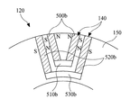
図1及び図5Aを参照すると、ローター120のモジュール140は、一対の第1永久磁石500a及び第1連結部510aを含む。第1連結部510aは、一対の第1永久磁石500aの一端を互いに連結する。例えば、第1連結部510aは、第1永久磁石500aのうちのローターコア150の内側方向に位置する部分を互いに連結することができる。第1連結部510aは、非磁性物質または空気で構成することができる。第1連結部510aは、ローターコア150の内側面と離隔して位置する。
1 and 5A, the
この際、第1永久磁石500aの内側は、N極どうしで対向するか、S極どうしで対向する形態になる。これにより、磁化方向は、第1永久磁石500aの外部から第1永久磁石500aを通過して、内部に移動する方向であるか、その反対である。
At this time, the inside of the first
図1及び図5Bを参照すると、ローター120のモジュール140は、一対の第1永久磁石500b、第1連結部510b、一対の第2永久磁石520b、及び第2連結部530bを含む。
1 and 5B, the
第1連結部510bは、一対の第1永久磁石500bの一端を互いに連結することができる。例えば、第1連結部510bは、第1永久磁石500bのうちのローターコア150の内側方向に位置する部分を互いに連結することができる。第1連結部510bは、非磁性物質または空気で構成することができる。第1連結部510bは、ローターコア150の内側面と離隔して位置する。
The first connecting
本実施例による第1連結部510bは、中心部分がハード磁性材料である連結部(‘図5Cの510c’)でもよい。
The first connecting
一対の第2永久磁石520bは、一対の第1永久磁石500bと離隔して位置しうる。
The pair of second
第2連結部530bは、一対の第2永久磁石520bの一端を互いに連結することができる。例えば、第2連結部530bは、第2永久磁石520bのうちのローターコア150の内側方向に位置する部分を互いに連結することができる。第2連結部530bは、非磁性物質または空気で構成することができる。第2連結部530bは、ローターコア150の内側面と離隔して位置する。
The second connecting
言い換えれば、第1永久磁石500b及び第1連結部510bを含むモジュール内に第2永久磁石520b及び第2連結部530bを含む小モジュールが形成されることが可能である。
In other words, a small module including the second
この際、第1永久磁石500bの内側は、N極どうしで対向するか、S極どうしで対向しており、第2永久磁石520bの内側は、第1永久磁石500bと同じ極性を有する。
At this time, the inner sides of the first
これにより、磁化方向は、第2永久磁石520aの外部で第1永久磁石500a及び第2永久磁石520aを通過して内部に向かう方向であるか、その反対である。
Thereby, the magnetization direction is a direction toward the inside through the first
永久磁石の個数を増加させることによって、永久磁石によって生成される磁束を増加させることができる。これにより、駆動モータ10の性能を向上させることができる。また、q軸電流による磁束の経路が追加されるために、q軸インダクタンスを増加させることができるので、駆動モータの性能向上が可能である。
By increasing the number of permanent magnets, the magnetic flux generated by the permanent magnets can be increased. Thereby, the performance of the
図1及び図5Cを参照すると、ローター120のモジュール140は、一対の第1永久磁石500c及び第1連結部510c、520cを含む。
1 and 5C, the
第1連結部510c、520cは、一対の第1永久磁石500cの一端を互いに連結することができる。例えば、第1連結部510c、520cは、第1永久磁石500cのうちのローターコア150の内側方向に位置する部分を互いに連結することができる。第1連結部510c、520cは、ローターコア150の内側面と離隔して位置する。
The first connecting
第1連結部510c、520cのうちの中心部分510cは、永久磁石であり、その他の部分520cは、非磁性物質または空気でもよい。
The
この際、第1永久磁石500cの内側は、N極どうしで対向するか、S極どうしで対向しており、第1連結部のうちの中心部分510cは、モジュールで発生する総磁束を増加させることができる極性でなければならない。例えば、第1連結部のうちの中心部分510cの内側極性は、第1永久磁石500cの内側極性と同一である。
At this time, the inner sides of the first
これにより、磁化方向は、第1永久磁石500cの外部から第1永久磁石500cを通過して、内部に向かう方向であるか、その反対である。
As a result, the magnetization direction is the direction from the outside of the first
ハード磁性材料である永久磁石510cがさらに含まれるために、永久磁石500c、510cによって生成される磁束がさらに増加することができる。これにより、駆動モータ10の性能が向上する。
Since the
図1及び図5Dを参照すると、ローター120のモジュール140は、一対の第1永久磁石500d、第1連結部510d、及び第3永久磁石520dを含む。
1 and 5D, the
第1連結部510dは、一対の第1永久磁石500dの一端を互いに連結する。例えば、第1連結部510dは、第1永久磁石500dのうちのローターコア150の内側方向に位置する部分を互いに連結することができる。第1連結部510dは、非磁性物質または空気で構成することができる。第1連結部510dは、ローターコア150の内側面と離隔して位置する。
The first connecting
第3永久磁石520dは、一対の第1永久磁石500dの間に位置し、ローターコア150の外側面側に位置する。
The third permanent magnet 520d is located between the pair of first
この際、一対の第1永久磁石の磁化方向は、N極どうしで対向するか、S極どうしで対向する形態になり、第3永久磁石は、モジュールで発生する総磁束を増加させる方向に磁化しなければならない。 At this time, the magnetization directions of the pair of first permanent magnets are such that the N poles face each other or the S poles face each other, and the third permanent magnets are magnetized in a direction to increase the total magnetic flux generated by the module. Must.
この際、第1永久磁石500dの内側は、N極どうしで対向するか、S極どうしで対向しており、第3永久磁石520dは、モジュールで発生する総磁束を増加させることができる極性でなければならない。例えば、第1永久磁石500dの内側極性がN極である場合、第3永久磁石520dの下側はNであり、上側はS極である。
At this time, the inner sides of the first
このように、第3永久磁石520dを追加することによって、永久磁石によって生成される磁束を増加させることができる。これにより、駆動モータ10の性能が向上する。
Thus, the magnetic flux generated by the permanent magnet can be increased by adding the third permanent magnet 520d. Thereby, the performance of the
図6A、図6B、及び図6Cは、本発明による駆動モータの性能を説明するための図であって、モータの電磁気的設計に使われるシミュレーションソフトウェアであるマックスウェル(Maxwell)を使ったシミュレーション結果である。 6A, 6B, and 6C are diagrams for explaining the performance of the drive motor according to the present invention, and are simulation results using Maxwell, which is simulation software used for electromagnetic design of the motor. It is.
式(1)及び図6Aを参照すると、一般的なspoke型駆動モータのLd値は、0.160mHであり、Lq値は、0.202mHであり、(Lq−Ld)値は、0.042mHである。一方、同じ量の磁石を使った本発明による駆動モータのLd値は、0.159mHであり、Lq値は、0.228mHであり、(Lq−Ld)値は、0.069mHである。本発明による駆動モータの(Lq−Ld)値は、一般的なspoke型駆動モータの(Lq−Ld)値に比べて、62.8%大きい(600a)。すなわち、本発明による駆動モータは、一般的な駆動モータに比べて、Ld及びLqの差値が大きい。 Referring to Equation (1) and FIG. 6A, the L d value of a general spoke type drive motor is 0.160 mH, the L q value is 0.202 mH, and the (L q −L d ) value is 0.042 mH. On the other hand, the L d value of the drive motor according to the present invention using the same amount of magnet is 0.159 mH, the L q value is 0.228 mH, and the (L q −L d ) value is 0.069 mH. It is. (L q -L d) value of the drive motor according to the present invention, as compared to typical of spoke-type drive motor (L q -L d) values, 62.8% greater (600a). That is, the drive motor according to the present invention has a large difference value between L d and L q compared to a general drive motor.
このように、本発明による駆動モータは、一般的なspoke型駆動モータに比べて、Ld及びLqの差値が大きいので、磁気抵抗トルクが大きくなる。高速運転時にマクネティックトルクに比べて、駆動モータのトルクに大きな影響を及ぼす磁気抵抗トルク値が大きいために、本発明による駆動モータは、一般的なspoke型駆動モータに比べて、高速運転時にも、高出力を保持することができる。 Thus, since the drive motor according to the present invention has a large difference value between L d and L q compared to a general spoke type drive motor, the magnetoresistive torque is increased. Since the magnetoresistive torque value that greatly affects the torque of the drive motor is larger than that of the magnetic torque during high-speed operation, the drive motor according to the present invention is more suitable for high-speed operation than the general spoke type drive motor. Even high output can be maintained.
図6Bは、モータの回転速度を上げながら、それによるトルクを計算したものである。図6Bを参照すると、本発明による駆動モータは、RPMが大きくなっても、一般的なspoke型駆動モータに比べて、急激にトルクが小さくならない(600b)。すなわち、本発明による駆動モータは、RPMが大きくなっても、大きなトルクを保持することができる。一方、一般的なspoke型駆動モータは、RPMが大きくなるにつれて急激にトルクが小さくなる(610b)。 FIG. 6B shows the torque calculated by increasing the rotational speed of the motor. Referring to FIG. 6B, the torque of the drive motor according to the present invention does not rapidly decrease even when the RPM increases (600b) as compared with a general spoke type drive motor. That is, the drive motor according to the present invention can maintain a large torque even when the RPM increases. On the other hand, in a general spoke type drive motor, the torque rapidly decreases as the RPM increases (610b).
このように、本発明による駆動モータは、高速運転時にも、大きなトルクを保持することができる。 Thus, the drive motor according to the present invention can maintain a large torque even during high-speed operation.
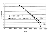
図6Cは、図6Bで計算された回転数及びトルク結果に基づいてモータの機械的出力を回転数によって表したものである。図6Cを参照すると、本発明による駆動モータは、RPMが大きくなっても、一般的なspoke型駆動モータに比べて、急激に出力が小さくならない(600c)。すなわち、本発明による駆動モータは、RPMが大きくなっても、大きな出力を保持することができる。一方、一般的なspoke型駆動モータは、RPMが大きくなるにつれて急激に出力が小さくなる(610c)。 FIG. 6C shows the mechanical output of the motor in terms of the number of revolutions based on the number of revolutions and the torque result calculated in FIG. 6B. Referring to FIG. 6C, the output of the drive motor according to the present invention does not decrease abruptly (600c) even when the RPM increases, compared to a general spike type drive motor. That is, the drive motor according to the present invention can maintain a large output even when the RPM increases. On the other hand, the output of a general spoke type drive motor rapidly decreases as the RPM increases (610c).
このように、本発明による駆動モータは、高速運転時にも、高出力を保持することができる。 Thus, the drive motor according to the present invention can maintain a high output even during high-speed operation.
説明された実施例は、多様な変形がなされるように、各実施例の全部または一部が選択的に組み合わせられて構成することもできる。 The described embodiments can be configured by selectively combining all or a part of the embodiments so that various modifications can be made.
また、実施例は、その説明のためのものであり、その制限のためのものではないということに注意しなければならない。また、当業者ならば、本発明の技術思想の範囲で多様な実施例が可能であるということを理解できるであろう。 It should also be noted that the examples are for purposes of illustration and not for limitation. Further, those skilled in the art will understand that various embodiments are possible within the scope of the technical idea of the present invention.
本発明は、ローター及び駆動モータ関連の技術分野に適用可能である。 The present invention is applicable to technical fields related to rotors and drive motors.
Claims (4)
中心部にシャフトと結合されるホールを含むローターコアと、
前記ローターコアに埋設される複数のモジュールであって、それぞれの前記モジュールは、前記シャフトの軸方向に垂直な断面において、前記ローターコアを挟んで前記ローターの半径方向外側に向かうにしたがって前記ローターの周方向の距離が大きくなるように前記ローターの周方向に離隔して位置して前記ローターコアの外側面まで延びる一対の第1永久磁石、前記一対の第1永久磁石のそれぞれの前記ホール側の一端と前記ローターコアによって囲まれる、前記ホールの表面から一定の間隔を有するように湾曲している第1空間部、及び前記ローターコアの前記外側面側に位置して前記一対の第1永久磁石のそれぞれの他端の間に直線状に延びる、他の永久磁石を含む、モジュールと、
を含み、
前記第1空間部のうちの中心部分は、永久磁石で構成され、その他の部分は、非磁性物質または空気で満たされる、
ローター。 A rotor,
A rotor core including a hole coupled to the shaft in the center,
A plurality of modules embedded in the rotor core , each of the modules in a cross section perpendicular to the axial direction of the shaft toward the radially outer side of the rotor across the rotor core; circumferential direction of the pair of first permanent magnets extending distance is positioned spaced apart in the circumferential direction of the rotor so as to increase to the outer surface of the rotor core, each of said holes side before Symbol pair of first permanent magnets A first space portion that is surrounded by one end of the rotor core and the rotor core and is curved so as to have a certain distance from the surface of the hole , and the pair of first permanent members positioned on the outer surface side of the rotor core. extending linearly between the respective other ends of the magnet, including other permanent magnets, and the module,
Only including,
The central part of the first space part is composed of a permanent magnet, and the other part is filled with a nonmagnetic substance or air.
rotor.
請求項1に記載のローター。 The number of modules is an even number, and the even number of modules is located in the rotor core at a predetermined interval in the circumferential direction of the rotor core in the cross section perpendicular to the axial direction of the shaft. located spaced apart from the table surface of the hole,
The rotor according to claim 1 .
請求項1又は2に記載のローター。 Before SL rotor core is composed of a soft magnetic material,
The rotor according to claim 1 or 2 .
前記ローターから離隔して位置し、コイルが巻かる少なくとも1つのスロットを含むステータと、
を有するモータ。
The rotor according to any one of claims 1 to 3 ,
A stator including at least one slot positioned away from the rotor and wound with a coil;
Having a motor.
Applications Claiming Priority (2)
| Application Number | Priority Date | Filing Date | Title |
|---|---|---|---|
| KR1020110050342A KR101786922B1 (en) | 2011-05-26 | 2011-05-26 | Rotor and driving motor |
| KR10-2011-0050342 | 2011-05-26 |
Publications (3)
| Publication Number | Publication Date |
|---|---|
| JP2012249517A JP2012249517A (en) | 2012-12-13 |
| JP2012249517A5 JP2012249517A5 (en) | 2015-05-14 |
| JP6423991B2 true JP6423991B2 (en) | 2018-11-14 |
Family
ID=46046026
Family Applications (1)
| Application Number | Title | Priority Date | Filing Date |
|---|---|---|---|
| JP2012120085A Active JP6423991B2 (en) | 2011-05-26 | 2012-05-25 | Rotor and drive motor |
Country Status (5)
| Country | Link |
|---|---|
| US (1) | US9083219B2 (en) |
| EP (1) | EP2528198A3 (en) |
| JP (1) | JP6423991B2 (en) |
| KR (1) | KR101786922B1 (en) |
| CN (1) | CN102801237B (en) |
Families Citing this family (19)
| Publication number | Priority date | Publication date | Assignee | Title |
|---|---|---|---|---|
| US9246364B2 (en) | 2012-10-15 | 2016-01-26 | Regal Beloit America, Inc. | Radially embedded permanent magnet rotor and methods thereof |
| US9882440B2 (en) | 2012-10-15 | 2018-01-30 | Regal Beloit America, Inc. | Radially embedded permanent magnet rotor and methods thereof |
| US9831727B2 (en) | 2012-10-15 | 2017-11-28 | Regal Beloit America, Inc. | Permanent magnet rotor and methods thereof |
| US9362792B2 (en) | 2012-10-15 | 2016-06-07 | Regal Beloit America, Inc. | Radially embedded permanent magnet rotor having magnet retention features and methods thereof |
| JP6074290B2 (en) * | 2013-03-04 | 2017-02-01 | アイチエレック株式会社 | Rotor and permanent magnet motor |
| US9837881B2 (en) * | 2013-04-16 | 2017-12-05 | Siemens Aktiengesellschaft | Method for producing an individual-segment rotor for an electric machine |
| EP2793365A1 (en) * | 2013-04-16 | 2014-10-22 | Siemens Aktiengesellschaft | Single segment rotor with single segments held by girders and method of manufacturing |
| KR102040147B1 (en) * | 2013-06-20 | 2019-11-04 | 삼성전자주식회사 | rotor for electric motor and electric motor using the same |
| CN105453395B (en) | 2013-08-09 | 2018-06-08 | 株式会社成田 | Magnetic force rotating device, motor and dynamotor |
| CN104682650A (en) * | 2013-11-28 | 2015-06-03 | 德昌电机(深圳)有限公司 | Motor rotor and brushless motor with motor rotor |
| CN106300730B (en) * | 2015-06-08 | 2019-01-01 | 珠海格力节能环保制冷技术研究中心有限公司 | Rotor and motor with it |
| DE102016207800A1 (en) * | 2016-05-04 | 2017-11-09 | Volkswagen Aktiengesellschaft | Rotor for an electric motor |
| FR3064837B1 (en) * | 2017-04-03 | 2020-01-17 | Moving Magnet Technologies | ROTOR FOR ELECTRIC MACHINE WITH INTERNAL PERMANENT MAGNETS |
| US10715017B2 (en) * | 2017-06-02 | 2020-07-14 | Hamilton Sundstrand Corporation | Hybrid synchronous machines |
| CN107733112A (en) * | 2017-09-18 | 2018-02-23 | 南京理工大学 | A kind of ultrahigh speed permanent-magnetic synchronous motor rotor structure |
| CN107681858A (en) * | 2017-09-18 | 2018-02-09 | 东南大学 | A kind of concentrated magnetic magnetic resistance offset motor |
| CN110061602B (en) * | 2018-12-26 | 2020-07-24 | 南方科技大学 | Rotor structure and permanent magnet excitation motor |
| DE102019102540A1 (en) * | 2019-02-01 | 2020-08-06 | Bayerische Motoren Werke Aktiengesellschaft | Embedded magnet arrangement for permanently excited electrical machines |
| CN211670689U (en) | 2019-07-19 | 2020-10-13 | 菲舍尔和佩克尔应用有限公司 | Electric motor and washing machine including the same |
Family Cites Families (20)
| Publication number | Priority date | Publication date | Assignee | Title |
|---|---|---|---|---|
| JPH0739091A (en) | 1993-07-19 | 1995-02-07 | Toyota Motor Corp | Rotor structure of synchronous machine and synchronous motor |
| JP3605475B2 (en) * | 1996-08-06 | 2004-12-22 | 松下電器産業株式会社 | Permanent magnet synchronous motor |
| TW364234B (en) * | 1997-04-14 | 1999-07-11 | Sanyo Electric Co | Rotor for an electric motor |
| JP2000060038A (en) | 1998-08-05 | 2000-02-25 | Toyota Motor Corp | Motor |
| JP2000102202A (en) * | 1998-09-22 | 2000-04-07 | Aichi Emerson Electric Co Ltd | Rotor for permanent-magnet type electric motor |
| JP3172506B2 (en) * | 1999-03-18 | 2001-06-04 | 株式会社東芝 | Permanent magnet type reluctance type rotating electric machine |
| JP2001145283A (en) * | 1999-11-19 | 2001-05-25 | Toyota Motor Corp | Rotor of permanent magnet rotary machine |
| JP2002186244A (en) | 2000-12-15 | 2002-06-28 | Mitsubishi Heavy Ind Ltd | Permanent magnet linear motor |
| JP4680442B2 (en) * | 2001-08-10 | 2011-05-11 | ヤマハ発動機株式会社 | Motor rotor |
| JP2003088019A (en) * | 2001-09-10 | 2003-03-20 | Fujitsu General Ltd | Permanent-magnet motor |
| JP3996417B2 (en) * | 2002-03-26 | 2007-10-24 | アイチエレック株式会社 | Permanent magnet motor |
| JP2004096850A (en) * | 2002-08-30 | 2004-03-25 | Toyo Electric Mfg Co Ltd | Rotor for induction start type synchronous dynamo-electric machine |
| DE10318624A1 (en) * | 2003-04-24 | 2004-11-25 | Minebea Co., Ltd. | Rotor body for an electric motor |
| EP1471621A3 (en) * | 2003-04-24 | 2005-12-14 | Minebea Co., Ltd. | Rotor element for an electrical motor |
| DE10345417A1 (en) * | 2003-09-30 | 2005-05-12 | Minebea Co Ltd | Permanent magnet rotor for electric motor has magnets in rotor connected together in pairs at their inner ends by auxiliary magnets |
| US7518278B2 (en) * | 2004-05-18 | 2009-04-14 | Ut-Battelle, Llc | High strength undiffused brushless machine and method |
| JP2006014457A (en) | 2004-06-24 | 2006-01-12 | Fanuc Ltd | Synchronous motor |
| KR100591338B1 (en) * | 2004-08-26 | 2006-06-19 | 엘지전자 주식회사 | Permanent Magnet Assisted SynRM and its method for impressing flux |
| KR20090027728A (en) * | 2006-06-12 | 2009-03-17 | 레미 인터내셔널, 인코포레이티드 | Electric machine with interior permanent magnets |
| US7902710B2 (en) * | 2008-10-01 | 2011-03-08 | Caterpillar Inc. | Electric machine |
-
2011
- 2011-05-26 KR KR1020110050342A patent/KR101786922B1/en active IP Right Grant
-
2012
- 2012-04-17 US US13/449,104 patent/US9083219B2/en active Active
- 2012-05-11 EP EP12167758.7A patent/EP2528198A3/en not_active Ceased
- 2012-05-21 CN CN201210158775.2A patent/CN102801237B/en active Active
- 2012-05-25 JP JP2012120085A patent/JP6423991B2/en active Active
Also Published As
| Publication number | Publication date |
|---|---|
| CN102801237A (en) | 2012-11-28 |
| EP2528198A3 (en) | 2015-10-28 |
| US20120299429A1 (en) | 2012-11-29 |
| US9083219B2 (en) | 2015-07-14 |
| KR20120131869A (en) | 2012-12-05 |
| JP2012249517A (en) | 2012-12-13 |
| EP2528198A2 (en) | 2012-11-28 |
| CN102801237B (en) | 2017-08-04 |
| KR101786922B1 (en) | 2017-10-18 |
Similar Documents
| Publication | Publication Date | Title |
|---|---|---|
| JP6423991B2 (en) | Rotor and drive motor | |
| JP5985342B2 (en) | Motor and rotor for motor | |
| JP5491484B2 (en) | Switched reluctance motor | |
| JP5961344B2 (en) | Magnetic flux concentrating type synchronous rotating electrical machine with permanent magnet | |
| US9006949B2 (en) | Synchronous motor | |
| CN112838693B (en) | Rotary electric machine | |
| KR102118152B1 (en) | Motor | |
| JP6158495B2 (en) | Rotor and electric motor including the same | |
| JP2011217601A (en) | Flux concentration type synchronous rotating electric machine with permanent magnet | |
| KR101981292B1 (en) | Permanent magnet motor rotor and permanent magnet synchronous motor | |
| US20110163618A1 (en) | Rotating Electrical Machine | |
| KR20150068632A (en) | Motor | |
| JP4580683B2 (en) | Permanent magnet type reluctance type rotating electrical machine | |
| US11837919B2 (en) | Rotary electric machine | |
| JP2018011466A (en) | Permanent-magnet embedded synchronous machine | |
| JP2013132124A (en) | Core for field element | |
| JP7047337B2 (en) | Permanent magnet type rotary electric machine | |
| JPWO2013065275A1 (en) | Motor rotor and motor equipped with the same | |
| JP6083640B2 (en) | Permanent magnet embedded motor | |
| JP6657928B2 (en) | Motor and method of adjusting magnetic flux of motor | |
| JP2018137853A (en) | Embedded-magnet synchronous motor | |
| WO2017050266A1 (en) | Magnetic flux switching type permanent magnet motor | |
| JP2012213269A (en) | Rotary electric machine | |
| JP5077369B2 (en) | Brushless motor | |
| JP2017143663A (en) | Embedded magnet type rotary machine |
Legal Events
| Date | Code | Title | Description |
|---|---|---|---|
| A521 | Request for written amendment filed |
Free format text: JAPANESE INTERMEDIATE CODE: A523 Effective date: 20150326 |
|
| A621 | Written request for application examination |
Free format text: JAPANESE INTERMEDIATE CODE: A621 Effective date: 20150326 |
|
| A131 | Notification of reasons for refusal |
Free format text: JAPANESE INTERMEDIATE CODE: A131 Effective date: 20160322 |
|
| A977 | Report on retrieval |
Free format text: JAPANESE INTERMEDIATE CODE: A971007 Effective date: 20160323 |
|
| A521 | Request for written amendment filed |
Free format text: JAPANESE INTERMEDIATE CODE: A523 Effective date: 20160616 |
|
| A02 | Decision of refusal |
Free format text: JAPANESE INTERMEDIATE CODE: A02 Effective date: 20161122 |
|
| A521 | Request for written amendment filed |
Free format text: JAPANESE INTERMEDIATE CODE: A523 Effective date: 20170322 |
|
| A911 | Transfer to examiner for re-examination before appeal (zenchi) |
Free format text: JAPANESE INTERMEDIATE CODE: A911 Effective date: 20170510 |
|
| A912 | Re-examination (zenchi) completed and case transferred to appeal board |
Free format text: JAPANESE INTERMEDIATE CODE: A912 Effective date: 20170630 |
|
| A521 | Request for written amendment filed |
Free format text: JAPANESE INTERMEDIATE CODE: A523 Effective date: 20180514 |
|
| A61 | First payment of annual fees (during grant procedure) |
Free format text: JAPANESE INTERMEDIATE CODE: A61 Effective date: 20181022 |
|
| R150 | Certificate of patent or registration of utility model |
Ref document number: 6423991 Country of ref document: JP Free format text: JAPANESE INTERMEDIATE CODE: R150 |
|
| R250 | Receipt of annual fees |
Free format text: JAPANESE INTERMEDIATE CODE: R250 |
|
| R250 | Receipt of annual fees |
Free format text: JAPANESE INTERMEDIATE CODE: R250 |
|
| R250 | Receipt of annual fees |
Free format text: JAPANESE INTERMEDIATE CODE: R250 |