JP6419694B2 - Transverse insertion spinal implant - Google Patents
Transverse insertion spinal implant Download PDFInfo
- Publication number
- JP6419694B2 JP6419694B2 JP2015520630A JP2015520630A JP6419694B2 JP 6419694 B2 JP6419694 B2 JP 6419694B2 JP 2015520630 A JP2015520630 A JP 2015520630A JP 2015520630 A JP2015520630 A JP 2015520630A JP 6419694 B2 JP6419694 B2 JP 6419694B2
- Authority
- JP
- Japan
- Prior art keywords
- plate
- spinal implant
- bore hole
- borehole
- spacer body
- Prior art date
- Legal status (The legal status is an assumption and is not a legal conclusion. Google has not performed a legal analysis and makes no representation as to the accuracy of the status listed.)
- Active
Links
Images


Classifications
-
- A—HUMAN NECESSITIES
- A61—MEDICAL OR VETERINARY SCIENCE; HYGIENE
- A61F—FILTERS IMPLANTABLE INTO BLOOD VESSELS; PROSTHESES; DEVICES PROVIDING PATENCY TO, OR PREVENTING COLLAPSING OF, TUBULAR STRUCTURES OF THE BODY, e.g. STENTS; ORTHOPAEDIC, NURSING OR CONTRACEPTIVE DEVICES; FOMENTATION; TREATMENT OR PROTECTION OF EYES OR EARS; BANDAGES, DRESSINGS OR ABSORBENT PADS; FIRST-AID KITS
- A61F2/00—Filters implantable into blood vessels; Prostheses, i.e. artificial substitutes or replacements for parts of the body; Appliances for connecting them with the body; Devices providing patency to, or preventing collapsing of, tubular structures of the body, e.g. stents
- A61F2/02—Prostheses implantable into the body
- A61F2/30—Joints
- A61F2/44—Joints for the spine, e.g. vertebrae, spinal discs
- A61F2/4455—Joints for the spine, e.g. vertebrae, spinal discs for the fusion of spinal bodies, e.g. intervertebral fusion of adjacent spinal bodies, e.g. fusion cages
- A61F2/447—Joints for the spine, e.g. vertebrae, spinal discs for the fusion of spinal bodies, e.g. intervertebral fusion of adjacent spinal bodies, e.g. fusion cages substantially parallelepipedal, e.g. having a rectangular or trapezoidal cross-section
-
- A—HUMAN NECESSITIES
- A61—MEDICAL OR VETERINARY SCIENCE; HYGIENE
- A61F—FILTERS IMPLANTABLE INTO BLOOD VESSELS; PROSTHESES; DEVICES PROVIDING PATENCY TO, OR PREVENTING COLLAPSING OF, TUBULAR STRUCTURES OF THE BODY, e.g. STENTS; ORTHOPAEDIC, NURSING OR CONTRACEPTIVE DEVICES; FOMENTATION; TREATMENT OR PROTECTION OF EYES OR EARS; BANDAGES, DRESSINGS OR ABSORBENT PADS; FIRST-AID KITS
- A61F2/00—Filters implantable into blood vessels; Prostheses, i.e. artificial substitutes or replacements for parts of the body; Appliances for connecting them with the body; Devices providing patency to, or preventing collapsing of, tubular structures of the body, e.g. stents
- A61F2/02—Prostheses implantable into the body
- A61F2/30—Joints
- A61F2/44—Joints for the spine, e.g. vertebrae, spinal discs
- A61F2/4455—Joints for the spine, e.g. vertebrae, spinal discs for the fusion of spinal bodies, e.g. intervertebral fusion of adjacent spinal bodies, e.g. fusion cages
- A61F2/4465—Joints for the spine, e.g. vertebrae, spinal discs for the fusion of spinal bodies, e.g. intervertebral fusion of adjacent spinal bodies, e.g. fusion cages having a circular or kidney shaped cross-section substantially perpendicular to the axis of the spine
-
- A—HUMAN NECESSITIES
- A61—MEDICAL OR VETERINARY SCIENCE; HYGIENE
- A61F—FILTERS IMPLANTABLE INTO BLOOD VESSELS; PROSTHESES; DEVICES PROVIDING PATENCY TO, OR PREVENTING COLLAPSING OF, TUBULAR STRUCTURES OF THE BODY, e.g. STENTS; ORTHOPAEDIC, NURSING OR CONTRACEPTIVE DEVICES; FOMENTATION; TREATMENT OR PROTECTION OF EYES OR EARS; BANDAGES, DRESSINGS OR ABSORBENT PADS; FIRST-AID KITS
- A61F2/00—Filters implantable into blood vessels; Prostheses, i.e. artificial substitutes or replacements for parts of the body; Appliances for connecting them with the body; Devices providing patency to, or preventing collapsing of, tubular structures of the body, e.g. stents
- A61F2/02—Prostheses implantable into the body
- A61F2/30—Joints
- A61F2/46—Special tools or methods for implanting or extracting artificial joints, accessories, bone grafts or substitutes, or particular adaptations therefor
- A61F2/4603—Special tools or methods for implanting or extracting artificial joints, accessories, bone grafts or substitutes, or particular adaptations therefor for insertion or extraction of endoprosthetic joints or of accessories thereof
- A61F2/4611—Special tools or methods for implanting or extracting artificial joints, accessories, bone grafts or substitutes, or particular adaptations therefor for insertion or extraction of endoprosthetic joints or of accessories thereof of spinal prostheses
-
- A—HUMAN NECESSITIES
- A61—MEDICAL OR VETERINARY SCIENCE; HYGIENE
- A61B—DIAGNOSIS; SURGERY; IDENTIFICATION
- A61B17/00—Surgical instruments, devices or methods, e.g. tourniquets
- A61B17/56—Surgical instruments or methods for treatment of bones or joints; Devices specially adapted therefor
- A61B17/58—Surgical instruments or methods for treatment of bones or joints; Devices specially adapted therefor for osteosynthesis, e.g. bone plates, screws, setting implements or the like
- A61B17/68—Internal fixation devices, including fasteners and spinal fixators, even if a part thereof projects from the skin
- A61B17/84—Fasteners therefor or fasteners being internal fixation devices
- A61B17/86—Pins or screws or threaded wires; nuts therefor
- A61B17/8605—Heads, i.e. proximal ends projecting from bone
- A61B17/861—Heads, i.e. proximal ends projecting from bone specially shaped for gripping driver
- A61B17/8615—Heads, i.e. proximal ends projecting from bone specially shaped for gripping driver at the central region of the screw head
-
- A—HUMAN NECESSITIES
- A61—MEDICAL OR VETERINARY SCIENCE; HYGIENE
- A61B—DIAGNOSIS; SURGERY; IDENTIFICATION
- A61B17/00—Surgical instruments, devices or methods, e.g. tourniquets
- A61B17/56—Surgical instruments or methods for treatment of bones or joints; Devices specially adapted therefor
- A61B17/58—Surgical instruments or methods for treatment of bones or joints; Devices specially adapted therefor for osteosynthesis, e.g. bone plates, screws, setting implements or the like
- A61B17/68—Internal fixation devices, including fasteners and spinal fixators, even if a part thereof projects from the skin
- A61B17/84—Fasteners therefor or fasteners being internal fixation devices
- A61B17/86—Pins or screws or threaded wires; nuts therefor
- A61B17/8625—Shanks, i.e. parts contacting bone tissue
- A61B17/863—Shanks, i.e. parts contacting bone tissue with thread interrupted or changing its form along shank, other than constant taper
-
- A—HUMAN NECESSITIES
- A61—MEDICAL OR VETERINARY SCIENCE; HYGIENE
- A61B—DIAGNOSIS; SURGERY; IDENTIFICATION
- A61B17/00—Surgical instruments, devices or methods, e.g. tourniquets
- A61B17/56—Surgical instruments or methods for treatment of bones or joints; Devices specially adapted therefor
- A61B17/58—Surgical instruments or methods for treatment of bones or joints; Devices specially adapted therefor for osteosynthesis, e.g. bone plates, screws, setting implements or the like
- A61B17/68—Internal fixation devices, including fasteners and spinal fixators, even if a part thereof projects from the skin
- A61B17/84—Fasteners therefor or fasteners being internal fixation devices
- A61B17/86—Pins or screws or threaded wires; nuts therefor
- A61B17/864—Pins or screws or threaded wires; nuts therefor hollow, e.g. with socket or cannulated
-
- A—HUMAN NECESSITIES
- A61—MEDICAL OR VETERINARY SCIENCE; HYGIENE
- A61F—FILTERS IMPLANTABLE INTO BLOOD VESSELS; PROSTHESES; DEVICES PROVIDING PATENCY TO, OR PREVENTING COLLAPSING OF, TUBULAR STRUCTURES OF THE BODY, e.g. STENTS; ORTHOPAEDIC, NURSING OR CONTRACEPTIVE DEVICES; FOMENTATION; TREATMENT OR PROTECTION OF EYES OR EARS; BANDAGES, DRESSINGS OR ABSORBENT PADS; FIRST-AID KITS
- A61F2/00—Filters implantable into blood vessels; Prostheses, i.e. artificial substitutes or replacements for parts of the body; Appliances for connecting them with the body; Devices providing patency to, or preventing collapsing of, tubular structures of the body, e.g. stents
- A61F2/02—Prostheses implantable into the body
- A61F2/30—Joints
- A61F2002/30001—Additional features of subject-matter classified in A61F2/28, A61F2/30 and subgroups thereof
- A61F2002/30003—Material related properties of the prosthesis or of a coating on the prosthesis
- A61F2002/3006—Properties of materials and coating materials
- A61F2002/3008—Properties of materials and coating materials radio-opaque, e.g. radio-opaque markers
-
- A—HUMAN NECESSITIES
- A61—MEDICAL OR VETERINARY SCIENCE; HYGIENE
- A61F—FILTERS IMPLANTABLE INTO BLOOD VESSELS; PROSTHESES; DEVICES PROVIDING PATENCY TO, OR PREVENTING COLLAPSING OF, TUBULAR STRUCTURES OF THE BODY, e.g. STENTS; ORTHOPAEDIC, NURSING OR CONTRACEPTIVE DEVICES; FOMENTATION; TREATMENT OR PROTECTION OF EYES OR EARS; BANDAGES, DRESSINGS OR ABSORBENT PADS; FIRST-AID KITS
- A61F2/00—Filters implantable into blood vessels; Prostheses, i.e. artificial substitutes or replacements for parts of the body; Appliances for connecting them with the body; Devices providing patency to, or preventing collapsing of, tubular structures of the body, e.g. stents
- A61F2/02—Prostheses implantable into the body
- A61F2/30—Joints
- A61F2002/30001—Additional features of subject-matter classified in A61F2/28, A61F2/30 and subgroups thereof
- A61F2002/30316—The prosthesis having different structural features at different locations within the same prosthesis; Connections between prosthetic parts; Special structural features of bone or joint prostheses not otherwise provided for
- A61F2002/30329—Connections or couplings between prosthetic parts, e.g. between modular parts; Connecting elements
- A61F2002/30476—Connections or couplings between prosthetic parts, e.g. between modular parts; Connecting elements locked by an additional locking mechanism
- A61F2002/305—Snap connection
-
- A—HUMAN NECESSITIES
- A61—MEDICAL OR VETERINARY SCIENCE; HYGIENE
- A61F—FILTERS IMPLANTABLE INTO BLOOD VESSELS; PROSTHESES; DEVICES PROVIDING PATENCY TO, OR PREVENTING COLLAPSING OF, TUBULAR STRUCTURES OF THE BODY, e.g. STENTS; ORTHOPAEDIC, NURSING OR CONTRACEPTIVE DEVICES; FOMENTATION; TREATMENT OR PROTECTION OF EYES OR EARS; BANDAGES, DRESSINGS OR ABSORBENT PADS; FIRST-AID KITS
- A61F2/00—Filters implantable into blood vessels; Prostheses, i.e. artificial substitutes or replacements for parts of the body; Appliances for connecting them with the body; Devices providing patency to, or preventing collapsing of, tubular structures of the body, e.g. stents
- A61F2/02—Prostheses implantable into the body
- A61F2/30—Joints
- A61F2002/30001—Additional features of subject-matter classified in A61F2/28, A61F2/30 and subgroups thereof
- A61F2002/30316—The prosthesis having different structural features at different locations within the same prosthesis; Connections between prosthetic parts; Special structural features of bone or joint prostheses not otherwise provided for
- A61F2002/30535—Special structural features of bone or joint prostheses not otherwise provided for
- A61F2002/30576—Special structural features of bone or joint prostheses not otherwise provided for with extending fixation tabs
- A61F2002/30578—Special structural features of bone or joint prostheses not otherwise provided for with extending fixation tabs having apertures, e.g. for receiving fixation screws
-
- A—HUMAN NECESSITIES
- A61—MEDICAL OR VETERINARY SCIENCE; HYGIENE
- A61F—FILTERS IMPLANTABLE INTO BLOOD VESSELS; PROSTHESES; DEVICES PROVIDING PATENCY TO, OR PREVENTING COLLAPSING OF, TUBULAR STRUCTURES OF THE BODY, e.g. STENTS; ORTHOPAEDIC, NURSING OR CONTRACEPTIVE DEVICES; FOMENTATION; TREATMENT OR PROTECTION OF EYES OR EARS; BANDAGES, DRESSINGS OR ABSORBENT PADS; FIRST-AID KITS
- A61F2/00—Filters implantable into blood vessels; Prostheses, i.e. artificial substitutes or replacements for parts of the body; Appliances for connecting them with the body; Devices providing patency to, or preventing collapsing of, tubular structures of the body, e.g. stents
- A61F2/02—Prostheses implantable into the body
- A61F2/30—Joints
- A61F2002/30001—Additional features of subject-matter classified in A61F2/28, A61F2/30 and subgroups thereof
- A61F2002/30316—The prosthesis having different structural features at different locations within the same prosthesis; Connections between prosthetic parts; Special structural features of bone or joint prostheses not otherwise provided for
- A61F2002/30535—Special structural features of bone or joint prostheses not otherwise provided for
- A61F2002/30593—Special structural features of bone or joint prostheses not otherwise provided for hollow
-
- A—HUMAN NECESSITIES
- A61—MEDICAL OR VETERINARY SCIENCE; HYGIENE
- A61F—FILTERS IMPLANTABLE INTO BLOOD VESSELS; PROSTHESES; DEVICES PROVIDING PATENCY TO, OR PREVENTING COLLAPSING OF, TUBULAR STRUCTURES OF THE BODY, e.g. STENTS; ORTHOPAEDIC, NURSING OR CONTRACEPTIVE DEVICES; FOMENTATION; TREATMENT OR PROTECTION OF EYES OR EARS; BANDAGES, DRESSINGS OR ABSORBENT PADS; FIRST-AID KITS
- A61F2/00—Filters implantable into blood vessels; Prostheses, i.e. artificial substitutes or replacements for parts of the body; Appliances for connecting them with the body; Devices providing patency to, or preventing collapsing of, tubular structures of the body, e.g. stents
- A61F2/02—Prostheses implantable into the body
- A61F2/30—Joints
- A61F2002/30001—Additional features of subject-matter classified in A61F2/28, A61F2/30 and subgroups thereof
- A61F2002/30316—The prosthesis having different structural features at different locations within the same prosthesis; Connections between prosthetic parts; Special structural features of bone or joint prostheses not otherwise provided for
- A61F2002/30535—Special structural features of bone or joint prostheses not otherwise provided for
- A61F2002/30604—Special structural features of bone or joint prostheses not otherwise provided for modular
- A61F2002/30607—Kits of prosthetic parts to be assembled in various combinations for forming different prostheses
-
- A—HUMAN NECESSITIES
- A61—MEDICAL OR VETERINARY SCIENCE; HYGIENE
- A61F—FILTERS IMPLANTABLE INTO BLOOD VESSELS; PROSTHESES; DEVICES PROVIDING PATENCY TO, OR PREVENTING COLLAPSING OF, TUBULAR STRUCTURES OF THE BODY, e.g. STENTS; ORTHOPAEDIC, NURSING OR CONTRACEPTIVE DEVICES; FOMENTATION; TREATMENT OR PROTECTION OF EYES OR EARS; BANDAGES, DRESSINGS OR ABSORBENT PADS; FIRST-AID KITS
- A61F2/00—Filters implantable into blood vessels; Prostheses, i.e. artificial substitutes or replacements for parts of the body; Appliances for connecting them with the body; Devices providing patency to, or preventing collapsing of, tubular structures of the body, e.g. stents
- A61F2/02—Prostheses implantable into the body
- A61F2/30—Joints
- A61F2002/30001—Additional features of subject-matter classified in A61F2/28, A61F2/30 and subgroups thereof
- A61F2002/30316—The prosthesis having different structural features at different locations within the same prosthesis; Connections between prosthetic parts; Special structural features of bone or joint prostheses not otherwise provided for
- A61F2002/30535—Special structural features of bone or joint prostheses not otherwise provided for
- A61F2002/30604—Special structural features of bone or joint prostheses not otherwise provided for modular
- A61F2002/30616—Sets comprising a plurality of prosthetic parts of different sizes or orientations
-
- A—HUMAN NECESSITIES
- A61—MEDICAL OR VETERINARY SCIENCE; HYGIENE
- A61F—FILTERS IMPLANTABLE INTO BLOOD VESSELS; PROSTHESES; DEVICES PROVIDING PATENCY TO, OR PREVENTING COLLAPSING OF, TUBULAR STRUCTURES OF THE BODY, e.g. STENTS; ORTHOPAEDIC, NURSING OR CONTRACEPTIVE DEVICES; FOMENTATION; TREATMENT OR PROTECTION OF EYES OR EARS; BANDAGES, DRESSINGS OR ABSORBENT PADS; FIRST-AID KITS
- A61F2/00—Filters implantable into blood vessels; Prostheses, i.e. artificial substitutes or replacements for parts of the body; Appliances for connecting them with the body; Devices providing patency to, or preventing collapsing of, tubular structures of the body, e.g. stents
- A61F2/02—Prostheses implantable into the body
- A61F2/30—Joints
- A61F2/30767—Special external or bone-contacting surface, e.g. coating for improving bone ingrowth
- A61F2/30771—Special external or bone-contacting surface, e.g. coating for improving bone ingrowth applied in original prostheses, e.g. holes or grooves
- A61F2002/30772—Apertures or holes, e.g. of circular cross section
- A61F2002/30784—Plurality of holes
- A61F2002/30785—Plurality of holes parallel
-
- A—HUMAN NECESSITIES
- A61—MEDICAL OR VETERINARY SCIENCE; HYGIENE
- A61F—FILTERS IMPLANTABLE INTO BLOOD VESSELS; PROSTHESES; DEVICES PROVIDING PATENCY TO, OR PREVENTING COLLAPSING OF, TUBULAR STRUCTURES OF THE BODY, e.g. STENTS; ORTHOPAEDIC, NURSING OR CONTRACEPTIVE DEVICES; FOMENTATION; TREATMENT OR PROTECTION OF EYES OR EARS; BANDAGES, DRESSINGS OR ABSORBENT PADS; FIRST-AID KITS
- A61F2/00—Filters implantable into blood vessels; Prostheses, i.e. artificial substitutes or replacements for parts of the body; Appliances for connecting them with the body; Devices providing patency to, or preventing collapsing of, tubular structures of the body, e.g. stents
- A61F2/02—Prostheses implantable into the body
- A61F2/30—Joints
- A61F2/30767—Special external or bone-contacting surface, e.g. coating for improving bone ingrowth
- A61F2/30771—Special external or bone-contacting surface, e.g. coating for improving bone ingrowth applied in original prostheses, e.g. holes or grooves
- A61F2002/30772—Apertures or holes, e.g. of circular cross section
- A61F2002/30784—Plurality of holes
- A61F2002/30787—Plurality of holes inclined obliquely with respect to each other
-
- A—HUMAN NECESSITIES
- A61—MEDICAL OR VETERINARY SCIENCE; HYGIENE
- A61F—FILTERS IMPLANTABLE INTO BLOOD VESSELS; PROSTHESES; DEVICES PROVIDING PATENCY TO, OR PREVENTING COLLAPSING OF, TUBULAR STRUCTURES OF THE BODY, e.g. STENTS; ORTHOPAEDIC, NURSING OR CONTRACEPTIVE DEVICES; FOMENTATION; TREATMENT OR PROTECTION OF EYES OR EARS; BANDAGES, DRESSINGS OR ABSORBENT PADS; FIRST-AID KITS
- A61F2/00—Filters implantable into blood vessels; Prostheses, i.e. artificial substitutes or replacements for parts of the body; Appliances for connecting them with the body; Devices providing patency to, or preventing collapsing of, tubular structures of the body, e.g. stents
- A61F2/02—Prostheses implantable into the body
- A61F2/30—Joints
- A61F2/30767—Special external or bone-contacting surface, e.g. coating for improving bone ingrowth
- A61F2/30771—Special external or bone-contacting surface, e.g. coating for improving bone ingrowth applied in original prostheses, e.g. holes or grooves
- A61F2002/30841—Sharp anchoring protrusions for impaction into the bone, e.g. sharp pins, spikes
- A61F2002/30843—Pyramidally-shaped
-
- A—HUMAN NECESSITIES
- A61—MEDICAL OR VETERINARY SCIENCE; HYGIENE
- A61F—FILTERS IMPLANTABLE INTO BLOOD VESSELS; PROSTHESES; DEVICES PROVIDING PATENCY TO, OR PREVENTING COLLAPSING OF, TUBULAR STRUCTURES OF THE BODY, e.g. STENTS; ORTHOPAEDIC, NURSING OR CONTRACEPTIVE DEVICES; FOMENTATION; TREATMENT OR PROTECTION OF EYES OR EARS; BANDAGES, DRESSINGS OR ABSORBENT PADS; FIRST-AID KITS
- A61F2310/00—Prostheses classified in A61F2/28 or A61F2/30 - A61F2/44 being constructed from or coated with a particular material
- A61F2310/00005—The prosthesis being constructed from a particular material
- A61F2310/00011—Metals or alloys
- A61F2310/00023—Titanium or titanium-based alloys, e.g. Ti-Ni alloys
-
- A—HUMAN NECESSITIES
- A61—MEDICAL OR VETERINARY SCIENCE; HYGIENE
- A61F—FILTERS IMPLANTABLE INTO BLOOD VESSELS; PROSTHESES; DEVICES PROVIDING PATENCY TO, OR PREVENTING COLLAPSING OF, TUBULAR STRUCTURES OF THE BODY, e.g. STENTS; ORTHOPAEDIC, NURSING OR CONTRACEPTIVE DEVICES; FOMENTATION; TREATMENT OR PROTECTION OF EYES OR EARS; BANDAGES, DRESSINGS OR ABSORBENT PADS; FIRST-AID KITS
- A61F2310/00—Prostheses classified in A61F2/28 or A61F2/30 - A61F2/44 being constructed from or coated with a particular material
- A61F2310/00005—The prosthesis being constructed from a particular material
- A61F2310/00011—Metals or alloys
- A61F2310/00035—Other metals or alloys
- A61F2310/00095—Niobium or Nb-based alloys
-
- A—HUMAN NECESSITIES
- A61—MEDICAL OR VETERINARY SCIENCE; HYGIENE
- A61F—FILTERS IMPLANTABLE INTO BLOOD VESSELS; PROSTHESES; DEVICES PROVIDING PATENCY TO, OR PREVENTING COLLAPSING OF, TUBULAR STRUCTURES OF THE BODY, e.g. STENTS; ORTHOPAEDIC, NURSING OR CONTRACEPTIVE DEVICES; FOMENTATION; TREATMENT OR PROTECTION OF EYES OR EARS; BANDAGES, DRESSINGS OR ABSORBENT PADS; FIRST-AID KITS
- A61F2310/00—Prostheses classified in A61F2/28 or A61F2/30 - A61F2/44 being constructed from or coated with a particular material
- A61F2310/00005—The prosthesis being constructed from a particular material
- A61F2310/00011—Metals or alloys
- A61F2310/00035—Other metals or alloys
- A61F2310/00131—Tantalum or Ta-based alloys
Description
脊椎すべり症とは、1つの椎骨がその下の椎骨上の前方に滑る場合を説明するために使用される用語である。これは通常、上椎骨に脊椎分離症があるために発生する。椎間板と椎間関節を含む、椎骨を整合する脊椎の2つの主要な部分が存在する。脊椎分離症が発生した場合、椎間関節はもはや椎骨背部を保持することはできない。椎間板は、増加する応力下でゆっくりと伸長することがあり、上部椎骨を前方に滑らせる。大部分の場合、椎間板の伸長は、少量の前滑りをもたらすのみである。 Spondylolisthesis is a term used to describe the case where one vertebra slides forward on the underlying vertebra. This usually occurs because of spondylolysis in the upper vertebra. There are two main parts of the spine that align the vertebrae, including the intervertebral disc and the facet joint. When spondylolysis occurs, the facet joint can no longer hold the back of the vertebra. The intervertebral disc may stretch slowly under increasing stress, causing the upper vertebra to slide forward. In most cases, the extension of the disc only results in a small amount of forward slip.
脊椎すべり症のための外科療法は、機械的症状と圧縮症状の両方が存在する場合、それらに対処する必要がある。手術の目的は、脊髄神経の圧迫を除去し(即ち、減圧)、胸椎/腰椎に安定性を提供することである。脊椎すべり症のほとんどの場合では、減圧は、脊髄器具を用いて1つの脊髄椎骨を隣接する脊髄椎骨(すなわち、脊椎固定術)に結合することを伴うべきである(即ち、しばしば使用されるインプラントは、治癒プロセスの補助に使用される)。 Surgical therapy for spondylolisthesis needs to deal with both mechanical and compression symptoms. The purpose of the surgery is to remove spinal nerve compression (ie, decompression) and provide stability to the thoracic / lumbar spine. In most cases of spondylolisthesis, decompression should involve using a spinal instrument to join one spinal vertebra to the adjacent spinal vertebra (ie spinal fusion) (ie often used implants) Is used to aid in the healing process).
他の場合、脊椎円板及び/又は椎体は、外傷、疾患、変性効果、又は長期間にわたる摩耗の結果、ずれたり又は損傷したりし得る。このずれ又は損傷は多くの場合、慢性的な腰痛を引き起こす。慢性的な腰痛を緩和するために、脊椎円板は、隣接する椎骨の少なくとも1つの全て又は一部とともに除去される。インプラントを、続いて、残りの骨の解剖学的構造の融合を促進するために挿入する。しかし、脊椎固定術の成功は、いくつかの要因のために限定されている。例えば、除去された椎間板によって残された腔を埋めるために使用されるスペーサ又はインプラント又はケージは、脊椎を支持するために十分な強度を有しない可能性がある。また、スペーサは、外科医によって配置された位置に留まることができなければならない。腔はまた、スペーサ周辺及び脊髄領域内の骨の成長を促進するためにそのような材料で構成されなければならない。 In other cases, the spinal disc and / or vertebral body may be displaced or damaged as a result of trauma, disease, degenerative effects, or prolonged wear. This misalignment or damage often causes chronic low back pain. To relieve chronic low back pain, the spinal disc is removed along with all or part of at least one of the adjacent vertebrae. The implant is then inserted to facilitate fusion of the remaining bone anatomy. However, the success of spinal fusion is limited due to several factors. For example, a spacer or implant or cage used to fill a cavity left by a removed disc may not have sufficient strength to support the spine. Also, the spacer must be able to remain in the position placed by the surgeon. The cavity must also be constructed of such materials to promote bone growth around the spacer and in the spinal cord region.
本開示は脊椎インプラントに関する。例えば、脊椎インプラントは、椎間板腔に挿入するために使用され得る。脊椎インプラントは、慢性的な腰痛を緩和し、脊椎インプラント周辺の骨の成長を促進するためにも使用され得る。脊椎インプラントは、2つの椎体間に配置され、少なくとも2つの係止ネジで固定され得る。 The present disclosure relates to spinal implants. For example, spinal implants can be used to insert into the disc space. The spinal implant can also be used to relieve chronic low back pain and promote bone growth around the spinal implant. A spinal implant can be placed between two vertebral bodies and secured with at least two locking screws.
脊椎インプラント例は、椎間スペーサ本体、プレート及び、少なくとも2つのネジを含む。椎間スペーサ本体は、一対の対向する側面を含む。プレートは、前面及び後面を備える。プレートは、少なくとも2つのネジで椎体に取り付けられるように構成される。例えば、プレートは、椎体にプレートを取り付けるための少なくとも1つの上部ボアホール及び少なくとも1つの下位ボアホールを含む。プレートは、プレートの中心線の中心から外れた少なくとも2つの下部ボアホール及び少なくとも2つの上部ボアホールを備え得る。 An example spinal implant includes an intervertebral spacer body, a plate, and at least two screws. The intervertebral spacer body includes a pair of opposing side surfaces. The plate includes a front surface and a rear surface. The plate is configured to be attached to the vertebral body with at least two screws. For example, the plate includes at least one upper bore hole and at least one lower bore hole for attaching the plate to the vertebral body. The plate may comprise at least two lower bore holes and at least two upper bore holes off-center from the center line of the plate.
プレートは、椎間スペーサ本体と嵌合するように構成される。プレートの後面の一部は椎体の壁に接触するように適合される。それぞれのボアホールは、プレートに対して固定された角度で挿通されるネジの先端の相補的なネジ付き領域と係合するよう適合されるネジ付き領域を含む。更に、少なくとも2つの上部ボアホール及び少なくとも2つの下部ボアホールに挿入されるネジは、それる角度を有する。ネジは、プレートの横方向の正中線の周りで非対称的にそれる。 The plate is configured to mate with the intervertebral spacer body. A portion of the posterior surface of the plate is adapted to contact the vertebral body wall. Each borehole includes a threaded region adapted to engage a complementary threaded region at the tip of a screw that is inserted at a fixed angle relative to the plate. Furthermore, the screws inserted into the at least two upper bore holes and the at least two lower bore holes have a turning angle. The screws deflect asymmetrically around the transverse midline of the plate.
椎間スペーサ本体の一対の対向する側面はまた、2つの椎体と接触し得る。椎間スペーサ本体の前側部分は、必要に応じて中央に湾曲する。ネジは、少なくとも2つの前方ネジと少なくとも2つの後方ネジとを含み得る。 A pair of opposing sides of the intervertebral spacer body can also contact the two vertebral bodies. The anterior portion of the intervertebral spacer body curves to the center as needed. The screws can include at least two front screws and at least two rear screws.
脊椎インプラントは、係止ネジであるネジも含み得る。プレートは必要に応じて、ボアホール内に円錐形の係止ネジ山を有する。係止ネジは、プレートにネジ込まれ、ボアホール内の円錐形の係止ネジ山に係止され得る。係止又は非係止ネジは、それる角度で、又はネジが横方向の正中線の周りで対称的に若しくは非対称的にそれる場所で第1及び第2の椎体に挿入され得る。 The spinal implant may also include a screw that is a locking screw. The plate optionally has a conical locking thread in the borehole. The locking screw can be screwed into the plate and locked to a conical locking thread in the borehole. Locked or non-locked screws can be inserted into the first and second vertebral bodies at an angle that deviates or where the screws deviate symmetrically or asymmetrically about the transverse midline.
椎間スペーサ本体はまた、複数の突出部を含み得る。これらの突出部は必要に応じて、第1の椎体と第2の椎体との間の椎間スペーサ本体を固定する。脊椎インプラントのプレートはまた、少なくとも3つのボアホールを含んでもよく、他の実施形態では、少なくとも2つのボアホールを含んでもよい。 The intervertebral spacer body may also include a plurality of protrusions. These protrusions secure the intervertebral spacer body between the first and second vertebral bodies as required. The plate of the spinal implant may also include at least three boreholes, and in other embodiments may include at least two boreholes.
本開示の実施のこれらの及び他の特徴及び利点は、本開示の好ましい実施及び代替実施の両方を説明する以下の詳細な説明並びに付属の図を鑑みることで、当業者には容易に理解されるであろう。 These and other features and advantages of implementations of the present disclosure will be readily understood by those of ordinary skill in the art in view of the following detailed description and accompanying drawings that illustrate both preferred and alternative implementations of the present disclosure. It will be.
図面において、様々な図面における同様の参照番号及び名称は同様の要素を示す。
ここで、本開示の実施について、より詳細に以下に説明する。実際、これらの実施は多くの異なる形体で具現化することができるものであり、本明細書に記載の実施に限定されると解釈されるべきではなく、むしろ、これらの実施は、該当する法的要件を本開示により満たすために提供される。本明細書及び添付の「特許請求の範囲」において使用されるとき、単数形「a」、「an」及び「the」は、その文脈において別段の明確な指示がない限り、複数の指示対象を包含する。本明細書で使用されるとき、用語「含む/備える(comprising)」及びその変化形は、用語「含む(including)」及びその変化形と同義語として使用されるオープンで非限定的な用語である。 Here, the implementation of the present disclosure will be described in more detail below. Indeed, these implementations can be embodied in many different forms and should not be construed as limited to the implementations set forth herein, but rather, these implementations are subject to applicable law. Are provided to meet the requirements of this disclosure. As used herein and in the appended claims, the singular forms “a”, “an”, and “the” refer to a plurality of referents unless the context clearly dictates otherwise. Include. As used herein, the term “comprising” and variations thereof are open, non-limiting terms that are used synonymously with the term “including” and variations thereof. is there.
背中の手術の広い範囲を実行する際に、外科医は、しばしば、茎ネジ及びロッドを利用する必要がある。これら茎ネジ及びロッドは、周囲の組織及び脈管構造系に対して侵入的な傾向がある剛性安定化システムの構成要素である。この脊椎インプラントは脊髄解剖学に適合であるだけでなく、外科医が茎ネジ及びロッドの使用を避けることを可能にするのに十分強力であるので、本開示は低侵入性である。本開示はまた、低侵襲手術及びより迅速な手術時間を可能にする。 In performing a wide range of back surgery, surgeons often need to utilize pedicle screws and rods. These pedicle screws and rods are components of a stiffness stabilization system that tends to be invasive to the surrounding tissue and vasculature. Not only is this spinal implant compatible with spinal cord anatomy, but the disclosure is less invasive because it is powerful enough to allow the surgeon to avoid the use of pedicle screws and rods. The present disclosure also allows for minimally invasive surgery and faster surgical times.
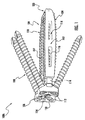
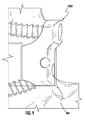
図1〜18は、本開示の実施形態の異なる図を示す。脊椎インプラント例100Aを、図1に示す。図1は、脊椎インプラント100Aの構成要素及び機構の導入としての役割を果たす。図2〜11で、脊椎インプラント100Aの様々な構成要素の詳細について示す。脊椎インプラント100Aは椎間スペーサ本体102及びプレート106を含む。椎間スペーサ本体102は、一対の対向する側面104の対を含む。それぞれの対向する側面104は、必要に応じて、椎体の上面及び底面に摩擦係合するように提供されるピラミッド型の歯118を有する。椎間スペーサ本体102は、中央窓117及び側窓116を含み得る。タンタルマーカを、中央部及び側窓116に近接して提供し得る。外科医又は他の任意の医療専門家は、患者の身体内のインプラント100Aの適切な配置を保証するために、タンタルマーカを表示する脊椎インプラント100Aが配置される領域のX線写真を撮ってもよい。椎間スペーサ本体102は、自己分散ブレットノーズ(bulletnose)120を含み得る。椎間スペーサ本体102は、必要に応じて、ポリエーテルエーテルケトン(PEEK)、医療用インプラントに適した任意の他の生体適合性材料で作製される。
1-18 illustrate different views of embodiments of the present disclosure. An example
プレート106は、前面及び後面で構成される。プレート106は、少なくとも2つの上部ボアホール110及び少なくとも2つの下部ボアホール110を含み、プレート106の中心線の周り及び前面及び後面を通ってそれぞれ配置され得る。少なくとも2つの上部ボアホール110及び少なくとも2つの下部ボアホール110は、プレート106内及びプレート106の中心線に対して1つ又は2つ以上のアライメントを有し得る。ボアホール110の更なる説明は、図6〜9を参照し、以下に提供される。プレート106は、スペーサ本体102に連結されるように適合される連結フランジ114を更に含む。プレート106はまた、椎間スペーサ本体102と嵌合するための領域を画定し得る。例えば、プレート106の後面の一部は椎体の壁に接触するように適合される。中心孔124は、スペーサ本体102及び/又は適切な挿入装置の取付物にプレート102を固定するためにネジ(図示せず)が挿入され得る挿入領域として提供される。プレート106は、TAN、外科的又は医療用装置に適した任意の他のチタン合金、又は任意の他の適切な材料を含み得る。
The
1つ又は2つ以上のネジ108は椎体にプレート106を取り付け、それらの間に椎間スペーサ本体102を固定する。ネジ108は、必要に応じて、チタン−6アルミニウム−7ニオブ合金(TAN)、外科的又は医療用装置に適した任意の他のチタン合金、又は任意の他の適切な材料を含む。
One or
図2〜7を参照して説明されるように、脊椎インプラント100Aの第1の実施形態は、スペーサ本体102A〜102D及びプレート106A〜106Dの多くの異なる組み合わせを含む。具体的には、様々なスペーサ本体102A〜102Dは、図2〜5に示されており、脊柱の特定の領域での使用に適合する構成を有する脊椎インプラント100Aを作成するために、図6〜9に示されるプレート106A〜106Dが互換的に取り付けられていてもよい。
As described with reference to FIGS. 2-7, the first embodiment of
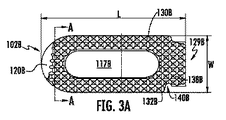
図2A〜2Fは、本開示の脊椎インプラント100Aを構築するために使用し得るスペーサ本体102Aの第1の実施形態を示す。図2A及び2Dに示すように、スペーサ本体102Aは、略円形の遠位端128A、及びプレート106の連結フランジ114に係合するように適合されるベース138Aを画定する近位端129Aを含む。スペーサ本体102Aは、直線状又は非直線状の側面130A及び132A及び中央窓117Aのいずれかを有する。中央窓117Aは、略楕円形状であるが、1つ又は2つ以上の円形領域、矩形領域、多角形状の領域などのような任意の形状又は形状(複数可)とすることができる。中央窓117Aは、中にスペーサ本体102Aが挿入される、隣接する椎体間の骨橋の成長を促進し得る。第1の実施形態に従い、スペーサ本体102Aは、約18mmの幅W及び約35〜55mmの長さLを有し得る。したがって、スペーサ本体102Aは、例えば、横方向手順に使用される場合、約1.8〜3.2の長さ対幅比を有し得る。
2A-2F illustrate a first embodiment of a
図2Bの断面図及び図2Cの拡大図に示すように、上面134A及び底面136Aはそれぞれ、側面130Aと132Aとの間に、R1A及びR2Aで表記される曲率半径を有する。したがって、上面134A及び底面136Aは、スペーサ本体102Aの横方向にわずかに湾曲している。曲率半径R1A及びR2Aは、隣接する椎体としっかりとした嵌合を達成するために、同一であっても異なっていてもよい。図2B及び図2Cは、患者の身体内に挿入される場合に脊椎インプラント100Aの位置を確認するために、適切な撮像装置を使用して表示し得るピン126Aを示す。ピン126Aは、約0.8mmの幅を有してもよく、例えば、X線にさらされる場合に可視化する、例えば、ステンレス鋼又は他の材料から作製し得る。
As shown in the cross-sectional view of FIG. 2B and the enlarged view of FIG. 2C, the
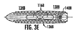
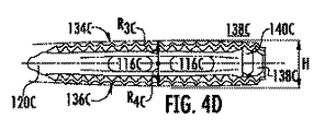
図2D及び2Eに示すように、スペーサ本体102Aの上面134A及び底面136Aはまたそれぞれ、遠位端128Aと近位端129Aとの間に、曲率半径R3A及びR4Aを有する。したがって、上面134A及び底面136Aは、スペーサ本体102Aの縦方向にわずかに湾曲している。曲率半径R3A及びR4Aは、隣接する椎体としっかりとした嵌合を達成するために、同一であっても異なっていてもよい。横方向及び/又は縦方向の上面134A及び底面136Aの曲率は、椎体の自然な輪郭内に受容し得る形状を提供する。
As shown in FIGS. 2D and 2E, the
図2D及び2Eはまた、より詳細に側窓116A及びピラミッド型の歯118Aを示す。側窓116Aは、楕円形、長円形、長方形、三角形、円形、多角形、及び/又はそれらの任意の組み合わせを含むがこれらに限定されない、任意の好適な形状を有し得る。歯118Aは、椎体と係合するのに好適な他の形状を有してもよい。凹部140Aは、スペーサ本体102Aの所定の位置にしっかりとプレート106をスナップするために、連結フランジ114の内向きの突出部150A/150B及び152A/152B(図6〜7を参照)を受容する側面130A及び132Aに画定される。いくつかの実施では、凹部140Aは、側壁130A及び132Aの一部のみに沿って延在する。本開示に従い、スペーサ本体102Aは、約6mm〜17mmの高さHを有し得る。
2D and 2E also show
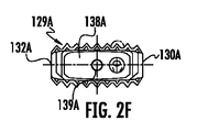
図2Fは、スペーサ本体102Aの近位端129Aの図である。ベース138Aは、連結フランジ114がそれに結合されている場合のようなスペーサ102A(図2A参照)の全幅よりも狭い幅を有することが画定され、ベース138Aの全幅及び連結フランジ114は、スペーサ本体102Aの幅にほぼ等しい。例えば、ベース138Aの幅は、プレート106の連結フランジ114間にしっかりと把持し得るような大きさであり得る。ベース138Aは更に、単に挿入のため又は長期の接続のために、スペーサ本体102Aにプレート106を固定するために使用されるネジ(図示せず)を受容し得る孔139Aを画定し得る。
FIG. 2F is a view of the
したがって、図2A〜2Fに示し、上述のように、医療専門家は、中にスペーサ本体が挿入される、隣接する椎体間の空隙に従い、適切なサイズのスペーサ本体102Aを選択することができる。
Thus, as shown in FIGS. 2A-2F and described above, a medical professional can select an appropriately
図3A〜3Fは、本開示の脊椎インプラント100Aを構築するために使用し得るスペーサ本体102Bの第2の実施形態を示す。スペーサ本体102Aの第1の実施形態と実質的に同様であるスペーサ本体102Bの態様は繰り返さない。
3A-3F illustrate a second embodiment of a spacer body 102B that may be used to construct a
図3Bの断面図及び図3Cの拡大図に示すように、上面134B及び底面136Bはそれぞれ、実質的に平坦である。図のように、側面132Bは、h1の高さを有し、側面130Bはh2の高さを有する。したがって、上面134A及び底面136Aは、高さh1及びh2によって画定される角度αを形成する。本開示に従い、高さh1及びh2は約5mm〜17mmの範囲であり得る。
As shown in the cross-sectional view of FIG. 3B and the enlarged view of FIG. 3C, the
図3Eに示すように、側面130Bに画定される凹部140Bは、側壁130Bの全体に沿って延在し、側部132Bに形成される凹部140Bは、側面132Bの一部に沿って延在する(図3A及び3Dを参照)。
As shown in FIG. 3E, the
図3Fは、スペーサ本体102Bの近位端129Bの図である。ベース138Bは、連結フランジ114がそれに結合されている場合のようなスペーサ102B(図3A参照)の全幅よりも狭い幅を有することが画定され、ベース138Bの全幅及び連結フランジ114は、スペーサ本体102Bの幅にほぼ等しい。ベース138Bは更に、スペーサ本体102Bにプレート106を固定するために使用されるネジ(図示せず)を受容し得る孔139Bを画定し得る。図示のように、ベース138Bは、それぞれ側面132B及び130Bの高さh1及びh2によって画定される同一の角度αを有するように形成される。
FIG. 3F is a view of the
したがって、図3A〜3Fに示し、上述のように、医療専門家は、中にスペーサ本体が挿入される、隣接する椎体間の空隙に従い、適切なサイズのスペーサ本体102Bを選択することができる。 Thus, as shown in FIGS. 3A-3F and described above, a medical professional can select an appropriately sized spacer body 102B according to the space between adjacent vertebral bodies into which the spacer body is inserted. .
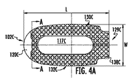
図4A〜4Fは、本開示の脊椎インプラント100Aを構築するために使用し得るスペーサ本体102Cの第3の実施形態を示す。スペーサ本体102Aの第1の実施形態と実質的に同様であるスペーサ本体102Cの第3の実施形態のそれらの態様は以下に繰り返さない。図4A及び4Dに示すように、スペーサ本体102Cは、略円形の遠位端128C、及びプレート106の連結フランジ114に係合するように適合されるベース138Cを画定する近位端129Cを含む。スペーサ本体102Cは、湾曲側面130C及び132C及び中央窓117Cを有する。第3の実施形態に従い、スペーサ本体102Cは、約22mmの幅W(最も幅の広い点間で測定されるとき)及び約35〜55mmの長さLを有し得る。したがって、スペーサ本体102Cは、例えば、横方向手順に使用される場合、約1.59〜2.5の長さ対幅比を有し得る。
4A-4F illustrate a third embodiment of a spacer body 102C that may be used to construct a
したがって、図4A〜4Fに示し、上述のように、医療専門家は、中にスペーサ本体が挿入される、隣接する椎体間の空隙に従い、適切なサイズのスペーサ本体102Cを選択することができる。 Thus, as shown in FIGS. 4A-4F and described above, a medical professional can select an appropriately sized spacer body 102C according to the space between adjacent vertebral bodies into which the spacer body is inserted. .
図5A〜5Fは、本開示の脊椎インプラント100Aを構築するために使用し得るスペーサ本体102Dの第4の実施形態を示す。スペーサ本体102Bの第2の実施形態と実質的に同様であるスペーサ本体102Dの態様は繰り返さない。
5A-5F illustrate a fourth embodiment of a spacer body 102D that may be used to construct the
図5A及び5Dに示すように、スペーサ本体102Cは、湾曲側面130C及び132C並びに中央窓117Cを含む。第4の実施形態に従い、スペーサ本体102Dは、約22mmの幅W(最も幅の広い点間で測定されるとき)及び約35〜55mmの長さLを有し得る。したがって、スペーサ本体102Dは、例えば、横方向手順に使用される場合、約1.59〜2.5の長さ対幅比を有し得る。 As shown in FIGS. 5A and 5D, the spacer body 102C includes curved side surfaces 130C and 132C and a central window 117C. According to the fourth embodiment, the spacer body 102D may have a width W of about 22 mm (when measured between the widest points) and a length L of about 35-55 mm. Thus, the spacer body 102D may have a length to width ratio of, for example, about 1.59 to 2.5 when used in a lateral procedure.
したがって、図5A〜5Fに示し、上述のように、医療専門家は、中にスペーサ本体が挿入される、隣接する椎体間の空隙に従い、適切なサイズのスペーサ本体102Dを選択することができる。 Thus, as shown in FIGS. 5A-5F and described above, a medical professional can select an appropriately sized spacer body 102D according to the gap between adjacent vertebral bodies into which the spacer body is inserted. .
図6A〜6Hは、本開示の第1の実施形態に従うプレート106Aを示す。第1の実施形態は、本開示に従い、いわゆる「非対称プレート」を示す。図6A及び6Bはそれぞれ、プレート106Aの前面及び後面斜視図を示す。プレート106Aは、側面158A及び160A、後面162A及び前面164Aを含む。円形の凹部157Aは、プレート106Aの側面158A及び160A内に形成され得る。ネジ(図示せず)を中に挿入して、上述の様々なスペーサ本体にプレート106Aを固定することができる中心孔124Aが提供される。中心孔124Aは、鍵付き凹部163A内に形成され得る。
6A-6H show a
図6Bにおいて、連結フランジ114A及びそれに関連する内向きの突出部150A及び152Aが示される。上述の通り、突出部150A及び152Aは、スペーサ本体102のベース138の凹部140内に受容される。連結フランジ114Aは、プレート106Aがそこに取り付けられる場合、スペーサ本体102のベース138に隣接する、実質的に平坦な壁166Aから延在する。図6A及び6Bに示すように、ボアホール110A1〜110A4は、ネジ108の相補的なネジ山を受容するように適合された係止ネジ山112Aを含み得る。
In FIG. 6B, connecting
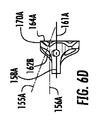
ここで図6Cを参照すると、側面160Aを示すプレート106Aの側面図が示される。下部ボアホール110A2及び110A4は、プレート106Aの横方向中心面161Aに平行するボアホール110A2及び110A4の中心を通る第1の水平軸154Aに対して約5度の角度で形成される中心軸153Aを有し得る。側面158Aを示す図6Dの側面図に示すように、上部ボアホール110A1及び110A3は、横方向中心面161Aに平行するボアホール110A1及び110A3の中心を通る第2の水平軸156Aに対して約20度の角度で形成される中心軸155Aを有し得る。
Referring now to FIG. 6C, a side view of the
図15A〜16Bに示すように、中心軸の上記ずれは、中に挿入されるネジ108を、プレート106Aの横方向中心面161Aの周りで非対称な角度でそらす。下部及び上部ボアホールの中心軸153A及び155Aが水平軸154A及び156Aに対して5度〜20度の任意の角度でずれていてもよいことに留意されたい。また、上部ボアホール及び下部ボアホールの中心軸が水平軸154A及び156Aに対して同一の角度であってもよく、それ故に中に挿入されるネジを、プレート106Aの横方向中心面161Aの周りで対称的な角度でそらすことに留意されたい。
As shown in FIGS. 15A-16B, the above misalignment of the central axis deflects the
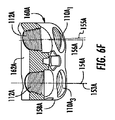
図6Eは、図6Cに示す下部ボアホール110A2及び110A4の断面図を示す。図6Fは、図6Dに示す上部ボアホール110A1及び110A3の断面図を示す。図6E及び6Fに示すように、係止ネジ山112Aは、ネジ108の頭部の相補係止ネジ山とねじ方式で係合するボアホール110A1〜110A4内に画定される。第1の実施形態に従い、上部及び下部ボアホール110A1及び110A2は、ボアホール110A1及び110A2の中心を通る、第2の水平軸156A及び第1の水平軸154Aそれぞれに対して、約3度の角度で横方向にずれている中心軸155A及び153Aを有し得る。側面158Aに近接して形成される上部及び下部ボアホール110A3及び110A4は、ボアホール110A3及び110A4の中心を通る、第2の水平軸156A及び第1の水平軸154Aそれぞれに対して、約1度の角度で横方向にずれている中心軸155A及び153Aを有し得る。第1の水平軸154A及び第2の水平軸156Aは、プレート106Aの縦方向の中心面165A(図6Hも参照)と平行する。
FIG. 6E shows a cross-sectional view of the lower bore holes 110 A2 and 110 A4 shown in FIG. 6C. Figure 6F shows a cross-sectional view of the upper borehole 110 A1 and 110 A3 shown in FIG. 6D. As shown in FIGS. 6E and 6F, the locking
ボアホール110A1〜110A4のそれぞれを、中に円錐面を形成する後面162Aに近接するよりも前面164Aにより幅広く近接するように先細にし得る。したがって、相補的な先細を有して挿入されるネジは、プレート106A内の所定位置で停止する。図のように、縦方向の中心面165Aによって画定されるように、ボアホール110A3及び110A4は、プレート106Aの中心から5.5mmで配置され得る一方で、ボアホール110A1及び110A2の中心は、プレート106Aの中心から5.3mmで配置され得る。
Each of the boreholes 110 A1 -110 A4 may be tapered to be closer to the
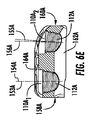
ここで図6Gを参照すると、プレート106Aの上面図が図示される。後面162Aは、平坦な壁166Aに対してプレート106Aの上部170Aから縦方向に移動する曲面を形成する(図6Bも参照)。図6Gには示さないが、後面162Aは、平坦な壁166Aに対してプレート106Aの底部172Aから縦方向に移動する同様の曲面を形成する。図示のように、上面170Aは、一般的に側面158Aから側面160A側に内側に湾曲し、湾曲の上位椎体の外壁に実質的に一致する領域174Aを形成する。同様の湾曲した領域は、湾曲の下位椎体の外壁に実質的に一致する底面172Aに近接する側面158Aから側面160Aに形成される。具体的には、湾曲領域174A(及び下部湾曲領域(図示せず))は、前面164Aの縁部及び側面160Aに近接して形成される曲率半径R6Aを有する、その一部を有し得る。更に、曲率半径R5Aを有する、前面164A及び側面158Aによって形成される縁部が形成され得る。
Referring now to FIG. 6G, a top view of the
図6Gに示すように、いくつかの実施では、連結フランジ114Aの長さは、揃わなくてもよい。連結フランジ114Aはそれぞれ、凹部140をスペーサ本体102に係合するため、上述のように内向きの突出部150A及び152Bをそれぞれ有し得る。例えば、前面164Aから測定されるとき、158Aに沿って延在するフランジは15mmの長さを有し得る。前面164Aから測定されるとき、160Aに沿って延在するフランジは13mmの長さを有し得る。同じ長さ、又は12mm〜16mmの長さの任意の組み合わせを有するフランジが形成され得る。フランジの内壁を、14mmの距離HFによって分離し得る。上述のように、距離HFは、スペーサ本体のベース138の幅と実質的に等しい任意の値であってよい。プレート106Aの幅Wは約19mmである。
As shown in FIG. 6G, in some implementations, the lengths of the connecting
図6Hは、プレート106Aの正面図を示す。図示のように、上部ボアホール110A1及び110A3は、横方向中心面161Aからの距離DUで、かつ縦側中心面165Aの周りに配置され得る。下部ボアホール110A2及び110A4は、横方向中心面161Aからの距離DLで、かつ縦側中心面165Aの周りに配置され得る。距離DUは、約2.75mm〜6.75mmの範囲であり得る。距離DLは、約6mm〜10mmの範囲であり得る。したがって、DL:DUの比率は、約1.4〜2.2である。プレート106Aは、約18mm〜26mmの範囲の高さHを有し得る。垂直方向のボアホールの外縁間の距離Qは約15mm〜23mmの範囲であり得、それ故にボアホールの外縁とプレート106Aの縁部との間に約1.5mmの材料を提供する。ボアホールの内縁間の距離Uは、約2.5mm〜10.5mmの範囲であり得る。図6Hにも示すように、前面164Aは、ボアホール間のプレート106Aの外縁に沿って形成されるディンプル176A及び178Aを有する実質的に矩形領域を画定する。プレート106Aは、側面158A及び160Aに形成されたディンプル間で測定されるとき、約18mmの幅を有し得る。したがって、ディンプル176A及び178Aは、プレート106Aを軽量化し、材料の約1mmを除去する。
FIG. 6H shows a front view of the
したがって、図6A〜6Hに示し、かつ上述のように、医療専門家は、脊椎インプラント手順を実行するために、脊椎インプラント100Aが植え込まれる脊椎の場所及びアクセス窓に従い、適切なサイズのプレート106Aを選択することができる。
Accordingly, as shown in FIGS. 6A-6H and described above, a medical professional may perform an appropriately
図7A〜7Hは、本開示の第2の実施形態に従うプレート106Bを示す。第2の実施形態は、本開示に従う、いわゆる「対称プレート」を示す。プレート106Aの第1の実施形態と同一であるプレート106Bの第2の実施形態のそれらの態様は以下に繰り返さない。
7A-7H show a
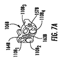
図7A及び7Bはそれぞれ、プレート106Bの前面及び後面斜視図を示す。プレート106Bは、側面158B及び160B、後面162B及び前面164Bを含む。ネジ(図示せず)を中に挿入して、上述の様々なスペーサ本体にプレート106Bを固定することができる中心孔124Bが提供される。
7A and 7B show front and rear perspective views of
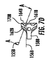
ここで図7Cを参照すると、側面160Bを示すプレート106Bの側面図が示される。下部ボアホール110B2及び110B4は、プレート106Bの横方向中心面161Bに平行するボアホール110B2及び110B4の中心を通る第1の水平軸154Bに対して約20度の角度で形成される中心軸153Bを有し得る。側面158Bを示す図7Dの側面図に示すように、上部ボアホール110B1及び110B3は、横方向中心面161Bに平行するボアホール110B1及び110B3の中心を通る第2の水平軸156Bに対して同様に約20度の角度で形成される中心軸155Bを有し得る。
Referring now to FIG. 7C, a side view of
図14A〜14Bに示すように、中心軸の上記ずれは、その中に挿入されるネジ108を、プレート106Bの横方向中心面161Bの周りで対称な角度でそらす。下部及び上部ボアホールの中心軸153B及び155Bが水平軸154B及び156Bに対して5度〜20度の任意の角度でずれていてもよいことに留意されたい。
As shown in FIGS. 14A-14B, the misalignment of the central axis deflects the
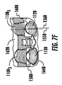
図7Hは、プレート106Bの正面図を示す。図示のように、上部ボアホール110B1及び110B3は、横方向中心面161Bからの距離DUで、かつ縦側中心軸165Bの周りに配置され得る。下部ボアホール110B2及び110B4は、横方向中心面161Bからの距離DLで、かつ縦側中心軸165Bの周りに配置され得る。距離DUは、約2.75mm〜6.75mmの範囲であり得る。同様に、距離DLは、約2.75mm〜6.75mmの範囲であり得る。プレート106Bが対称形状であるため、DL:DUの比率は1で維持され、それ故に、DL及びDUは、プレート106Bに実装されるDL及びDUの全てのサイズと等しい。プレート106Bは、約15mm〜23mmの範囲の高さHを有し得る。垂直方向のボアホールの外縁間の距離Qは、約12mm〜20mmの範囲であり得、それ故にボアホールの外縁とプレート106Bの縁部との間に約1.5mmの材料を提供する。ボアホールの内縁の間の距離Uは、約0.5mm〜8.5mmの範囲であり得る。図7Hにも示すように、前面164Bは、ボアホール間のプレート106Bの外縁に沿って形成されるディンプル176B及び178Bを有する実質的に矩形領域を画定する。プレート106Bは、側面158B及び160Bに形成されたディンプル間で測定されるとき、約18mmの幅を有し得る。したがって、ディンプル176B及び178Bは、プレート106Bを軽量化し、材料の約1mmを除去する。
FIG. 7H shows a front view of the
したがって、図7A〜7Hに示し、かつ上述のように、医療専門家は、脊椎インプラント手順を実行するために、脊椎インプラント100Bが植え込まれる脊椎の場所及びアクセス窓に従い、適切なサイズのプレート106Bを選択することができる。
Accordingly, as shown in FIGS. 7A-7H and as described above, a medical professional may perform the spinal implant procedure according to the location of the spine into which the
図8は、本開示の第3の実施形態に従うプレート106Cを示す。プレート106Cは、プレート106Aと比較して低減された高さDLを特徴とする。例えば、高さ低減は約2mm〜4mmとし得る。図示のように、上部ボアホール110C1及び110C3は、横方向中心面161Cからの距離DUで配置され得る。下部ボアホール110C2及び110C4は、横方向中心面161Aからの距離DLで配置され得る。距離DUは、約2.75mm〜6.75mmの範囲であり得る。距離DLは、約3mm〜7mmの範囲であり得る。したがって、DL:DUの比率は、約0.92〜1.0である。プレート106Cは、約15mm〜23mmの範囲の高さHを有し得る。垂直方向のボアホールの外縁間の距離Qは、約12mm〜20mmの範囲であり得、それ故にボアホールの外縁とプレート106Cの縁部との間に約1.5mmの材料を提供する。ボアホールの内縁間の距離Uは、約2.5mm〜10.5mmの範囲であり得る。他の態様では、プレート106Cはプレート106Aと実質的に同じ寸法及び特徴を有する。
FIG. 8 shows a plate 106C according to a third embodiment of the present disclosure. Plate 106C is characterized by a height D L which is reduced compared to the
プレート106Cは、プレート106Cを有する組み立てられた脊椎インプラントを用いて仙骨付近で作業する場合、脊髄領域で作業する外科医又は任意の他の医療専門家が腸骨稜との干渉を回避し得ることを可能にする。プレート106Cはまた、骨棘が存在する場合に、より少ない骨の除去も可能にする。なお更に、プレート106Cは、ボアホール110C1〜110C4に挿入される場合、ネジ108が板腔により近い骨を貫通することを可能にし、それ故にネジ108の露出を減らし、板腔内に突出するネジ108の危険性を軽減する。
Plate 106C is such that when working near the sacrum using an assembled spinal implant with plate 106C, a surgeon or any other medical professional working in the spinal cord area can avoid interference with the iliac crest. to enable. Plate 106C also allows for less bone removal when osteophytes are present. Still further, plate 106C is, when inserted into the borehole 110 C1 to 110 C4, allows the
図9は、本開示の第4の実施形態に従うプレート106Dを示す。プレート106Dはプレート106Cと同様であるが、プレート106Dは、内側−横方向平面内の解剖学的構造の特定の部分、及び頭側−尾側平面と同一平面に取り付けられるように構成される。図示のように、プレート106Dは、患者への刺激を引き起し得る、プレート106Cに関連付けられた材料が除去された部分902を提供する。
FIG. 9 shows a plate 106D according to a fourth embodiment of the present disclosure. Plate 106D is similar to plate 106C, but plate 106D is configured to be mounted flush with a particular portion of anatomy in the medial-lateral plane and the cranial-caudal plane. As shown, plate 106D provides a
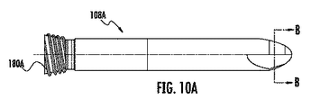
図10A〜10Cは本開示のネジ108Aの第1の実施形態を示す。ネジ108Aは、ネジ付き頭部180A及びネジ本体186Aを含む。したがって、ネジ本体186Aは、椎体の皮質骨への十分なネジの引っ掛かりを提供する比較的粗いピッチを有する。ネジ108Aは、可変角度付きネジ先188Aを有し、このネジ先は最初に約18度の角度、続いて、約22度の角度でその第1のネジ山に近接する。ネジ108Aの頭部は、ネジを回すために相補的星型ドライバを挿入し得る星状の凹部181Aを画定する。凹部は、相補的な駆動を受容するために、線、プラス記号、正方形又は他の多角形の形状などの他の形状を有するように形成され得る。ネジ108Aは、20mm〜50mmの範囲であり得る長さを有し得る。
10A-10C illustrate a first embodiment of the
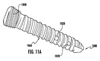
図11A〜11Bは、ネジ108Bの第2の実施形態を示す。ネジ108Bはサイズ及び形状においてネジ108Aと同様の特徴を共有するが、骨セメント又は他の接着剤を注入し得る中空中心部189Bを有する。ネジ108Bを、受容する骨が構造的に不健全であり、ネジ108Bを保持し得ない状況で使用し得る。ネジ108Bは、例えば、凹部181B内の射出機構のルアーロックを提供し得る。骨セメント又は他の接着剤は、それが、例えば、椎体内にネジ108Bを固定するために、ネジ山及び周囲の骨にネジ108Bの中央中空領域189B内及びホール182Bの外に流れるように、ネジ108Bに注入し得る。
11A-11B show a second embodiment of screw 108B. Screw 108B shares similar characteristics in size and shape as
図12A〜12Bを参照して、例えば、スペーサ本体102C及びプレート106Bを使用した脊椎インプラント100Aの組み立ての順序例が示される。図示のように、プレート106B及びスペーサ本体102Cは、協働して、互いに嵌合するように構成される。図12A〜12Bの順序では、連結フランジ114は側面130A及び132Aに画定される凹部140A内に圧入され、スペーサ本体102Cの所定の位置にしっかりとプレート106Bをスナップするために、連結フランジ114の内向きの突出部150B及び152Bを受容する。したがって、脊椎インプラント100Aは脊髄修復手順の一部として、医療専門家による使用のための準備ができている。
12A-12B, an example sequence of assembly of
図13を参照して、中に挿入されたネジ108と一緒になって、組み立てられた脊椎インプラント100Aが図示される。図13に示すように、挿入されるネジ頭は、部分的に、上面134と底面136との間のスペーサ102の高さによって画定される腔1102内に含まれる。ネジが垂直方向に互いに近接して位置付けられるため、そのような配置は、より小型のアクセス窓の領域を提供する。本開示の態様に従い、ネジ付き頭部180と係止ネジ山112との係合は、プレート106に対するネジ108の角度を修正する。
Referring to FIG. 13, an assembled
ここで図14〜18を参照して説明するように、脊椎インプラント100は、2つの椎体間の椎間腔内に横方向に挿入され得る。例えば、脊椎インプラント100を使用して、溶解性脊椎すべり症に対して優れた安定性を付与するか又は椎間板切除術後の骨格的に成熟した個体に構造的安定性を提供することができる。本開示の実施形態を、腰部L1〜L4又は胸部T9〜T12で、その周りで、又はその中で作業するために使用し得る。あるいは、インプラント100(長さ対幅の比率が変化する)は、2つの椎体間の椎間腔内に前側に植え込まれ得る。 As will now be described with reference to FIGS. 14-18, the spinal implant 100 may be inserted laterally into the intervertebral space between the two vertebral bodies. For example, spinal implant 100 can be used to confer excellent stability against lytic spondylolisthesis or provide structural stability to skeletal mature individuals after discectomy. Embodiments of the present disclosure may be used to work on or around waists L1-L4 or chests T9-T12. Alternatively, the implant 100 (the ratio of length to width varies) can be implanted anteriorly into the intervertebral space between the two vertebral bodies.
図14A〜14Cを参照して、一般に2つの椎体202及び204間の椎間板腔に配置される、脊椎インプラント例が図示される。脊椎インプラント100Aは、スペーサ本体102A〜102D及びプレート106Bのいずれかを含んでもよく、それ故にネジ108が対称的にそれることを提供する。プレート106のボアホール110B1〜110B4は、プレート106Bの角部付近に配置され、それ故に、最も強い、椎体202及び204の部分と一致するようにネジ108を配置する。プレート106の角部は皮質周縁部と整列し、それ故に所望の位置にインプラント100を保持するように係合するネジ108のための皮質骨の十分な量を提供する。
With reference to FIGS. 14A-14C, an example spinal implant is shown that is typically placed in the disc space between two
図14Bに示すように、上部ネジ108及び下部ネジ108は、インプラント100の正中線109から対称な角度でそれる。上述の通り、ネジ108が正中線109から対称的にそれる場合、ネジは中心線109に対して横方向アプローチで10度〜30度、及び前方アプローチで20度〜45度の角度でそれてもよい。図14Cに示すように、図7E及び7Fに示し、図6E及び6F及びボアホール110B1〜110B4に関して詳述したように、前方のネジは、約0度〜3度の角度で後方に曲がり得、後方のネジは、約0度〜3度であり得る角度で前方に曲がり得る。裏向きから椎体202又は204の壁を貫通するネジ108の端部の懸念を回避する一方、ネジ頭180及び係止ネジ山112の前述の係合のためにネジのそれる角度が固定され、それ故に本体内での脊椎インプラント100の安定性を増加させる。
As shown in FIG. 14B, the
図14Cにも示すように、プレート106の上面170Bは、湾曲の上位椎体の外壁に実質的に一致するように、一般的に内側に湾曲する。同様の湾曲した領域は、湾曲の下位椎体の外壁に実質的に一致するプレート106の底面側から形成される。したがって、プレート106は、椎体の外表面との良好な適合を達成する。例えば、プレート106の曲率は、プレート106の後面162と椎体202及び204の外壁との間に存在し得るあらゆる隙間を減少させるか又は排除し、それ故により多くの安定性を提供する(領域111を参照)。
As also shown in FIG. 14C, the
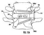
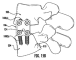
ここで図15A〜15Bを参照すると、2つの椎体間に植え込まれた、脊椎インプラント100Aが図示される。脊椎インプラント100Aは、スペーサ本体102A〜102D及びプレート106Aのいずれかを含んでもよく、それ故にネジ108が非対称的にそれることを提供する。図示のように、上部ネジ108及び下部ネジ108は、インプラント100の正中線109から非対称な角度でそれる。図示のように、上部ネジ108(a)が中心線109に対して0度〜10度の角度でそれてもよい一方で、下部ネジ108(b)は中心線109に対して10度〜30度の角度でそれてもよい。図15A〜15Bの実施は、腸骨稜付近で作業する場合、上部ネジ108の「平面性」又は小さな角度が腸骨稜と干渉しないために有益である。図示しないが、図14Cに関して上述のように、前方のネジは後方に曲がり得、後方のネジは前方に曲がり得る。
Referring now to FIGS. 15A-15B, a
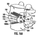
図16A〜16D、は、一般に2つの椎体202と204との間の椎間板腔に配置される、脊椎インプラント例を示す。例えば、脊椎の腰部又は胸部で作業する場合、図16A〜16Dに示す脊椎インプラント100を使用し得る。脊椎インプラント100は、変更のように(下記図16D参照した考察を参照)スペーサ本体102A〜102D及びプレート106Cのいずれかを含んでもよく、それ故にネジ108が非対称的にそれることを提供する。図16Bに示すように、上部ネジ108及び下部ネジ108は、インプラント100の正中線109から非対称な角度でそれる。図示のように、上部ネジ108(a)が中心線109に対して0度〜10度の角度でそれてもよい一方で、下部ネジ108(b)は中心線109に対して10度〜30度の角度でそれてもよい。図示しないが、図14Cに関して上述のように、前方のネジは後方に曲がり得、後方のネジは前方に曲がり得る。
FIGS. 16A-16D illustrate an example spinal implant that is typically placed in the disc space between two
図16Dに示すように、図8に記載したプレート106Cの高さの減少を提供するために、スペーサ本体102A〜102Dの底面136A〜136Dを変更して、プレート106Cのボアホール110C2及び110C4と整列するガイド溝1600を画定し得る。このように、ネジ108がボアホール110C2又は110C4に挿入されると、ネジは、椎体(例えば、椎体202及び204)の皮質骨を貫通する前に、ボアホール110C2又は110C4の内部を通って、ガイド溝1600を通過する。
As shown in FIG. 16D, in order to provide a reduction in the height of the plate 106C as described in FIG. 8, by changing the
プレート106Cを含む脊椎インプラント100は、プレート106Cを有する組み立てられた脊椎インプラントを用いて仙骨付近で作業する場合、脊髄領域で作業する外科医又は任意の他の医療専門家が腸骨稜との干渉を回避し得ることを可能にする。プレート106Cはまた、骨棘が存在する場合に、より少ない骨の除去も可能にする。 A spinal implant 100 that includes a plate 106C may interfere with the iliac crest when a surgeon or any other medical professional working in the spinal cord region works when working near the sacrum using an assembled spinal implant having the plate 106C. Allows to be avoided. Plate 106C also allows for less bone removal when osteophytes are present.
図17A〜17C、は、一般に2つの椎体202と204との間の椎間板腔に配置される、別の脊椎インプラント例を示す。脊椎インプラント100は、図16Dでの変更のように、スペーサ本体102A〜102D及びプレート106Dのいずれかを含んでもよく、それ故にネジ108が非対称的にそれることを提供する。図17Bに示すように、上部ネジ108及び下部ネジ108は、インプラント100の正中線109から非対称な角度でそれる。図示のように、上部ネジ108(a)が中心線109に対して0度〜10度の角度でそれてもよい一方で、下部ネジ108(b)は中心線109に対して10度〜30度の角度でそれてもよい。図示しないが、図14Cに関して上述のように、前方のネジは後方に曲がり得、後方のネジは前方に曲がり得る。
17A-17C illustrate another example spinal implant that is typically placed in the disc space between the two
図17A〜17Cの例では、脊椎インプラント100、具体的には、プレート106Dは、内側−横方向平面内の解剖学的構造の特定の部分、及び頭側−尾側平面と同一平面に取り付けられるように必要に応じて構成される。図示のように、プレート106Dは、プレート106Dに関連付けられた材料が除去された部分902を提供する。
In the example of FIGS. 17A-17C, spinal implant 100, specifically plate 106D, is mounted flush with a particular portion of the anatomy in the medial-lateral plane and the cranial-caudal plane. Configured as needed. As shown, plate 106D provides a
図18A〜18Bを参照して、脊椎インプラント手順中に開き得るアクセス窓の比較が図示される。図18Aは、プレート106C又は106Dの一方が利用される場合のアクセス窓を示す図である。ネジ108の配置が、0度で実施される場合、脊椎インプラント100は、同等のアクセス窓を可能にする。図示のように、プレート106C又は106Dは、椎体202の外壁に対して約1mm〜2mmの張り出しを有する。しかし、椎体204に関しては張り出しはない。図18Bでは、対照的に、プレート106Aを使用した脊椎インプラントを示す。図18Bでは、アクセス窓は、わずかに大きいプレート106Aのボアホールを通してネジ108の挿入に適応するためにわずかに大きくなっている。
With reference to FIGS. 18A-18B, a comparison of access windows that may be opened during a spinal implant procedure is illustrated. FIG. 18A shows an access window when one of the plates 106C or 106D is used. If the placement of the
図19A〜19Cは、本開示の別の脊椎インプラント100Bを示す図である。脊椎インプラント100Bは、第5の実施形態に従い、ボアホール110及びネジ108がプレート106Eの正中線125に沿って整列されることが図示される。ボアホール110とネジ108の集中場所は、ネジ108が前部皮質を突破するリスクの発生がより少なく、それ故に血管損傷を引き起こす可能性を減少させる。図19Aでは、側面160Eを示すプレート106Eの側面図が示される。下部ボアホール110E2は、プレート106Eの横方向中心面161Eに対して約20度の角度で形成され得る。上部ボアホール110E1は、横方向中心面161Eに対して約20度の角度で形成され得る。
19A-19C illustrate another
図19Cの正面図で、上部ボアホール110E1は、横方向中心面161Eからの距離DUで配置され得る。下部ボアホール110E2は、横方向中心面161Eからの距離DLで配置され得る。距離DUは、約2.75mm〜6.75mmの範囲であり得る。同様に、距離DLは、約2.75mm〜6.75mmの範囲であり得る。プレート106Eが対称形状であるため、DL:DUの比率は1で維持され、それ故に、DL及びDUは、プレート106Eに実装されるDL及びDUの全てのサイズと等しい。プレート106Eは、約15mm〜23mmの範囲の高さHを有し得る。垂直方向のボアホールの外縁間の距離Qは、約12mm〜20mmの範囲であり得、それ故にボアホールの外縁とプレート106Eの縁部との間に約1.5mmの材料を提供する。ボアホールの内縁間の距離Uは、約0.5mm〜8.5mmの範囲であり得る。
In the front view of FIG. 19C, the upper borehole 110 E1 can be arranged at a distance D U from
図19Bに示すように、中心軸の上記ずれは、中に挿入されたネジ108を、プレート106Eの横方向中心面161Eの周りで対称な角度でそらす。下部及び上部ボアホールの中心軸153E及び155Eが水平軸154E及び156Eに対して5度〜20度の任意の角度でずれていてもよいことに留意されたい。図示しないが、プレート106Aに関して上述のように、プレート106Eはネジが非対称的にそれることを提供し得る。プレート106Aと同様の可能性のあるプレート106Eの他の態様は、例えば、プレート106Eの後面は、椎体202及び204の外壁とのより良い適合を提供するために湾曲していてもよい。
As shown in FIG. 19B, the above misalignment of the central axis deflects the
図20を参照すると、代替のネジ位置を提供するための第6実施形態に従うプレート106Fを有する別の脊椎インプラント100Cが図示される。脊椎インプラント100Cは、外科医又は医療専門家が、プレート106Fがプレート106Fの中心線107Fに近接するボアホール110を備えるため、ネジ108を配置するために必要な開口部を最小化することを可能にする。
Referring to FIG. 20, another spinal implant 100C having a
具体的には、プレート106Fを、プレート106Bから除去されたボアホール110B2及び110B3を含むプレート106Bと同様に構成し得る。下部ボアホール110F2は、プレート106Fの横方向中心面161Fに対して約20度の角度で形成され得る。上部ボアホール110F1は、横方向中心面161Fに対して約20度の角度で形成され得る。これは、中に挿入されるネジ108を、プレート106Fの横方向中心面161Fの周りで対称な角度でそらす。下部及び上部ボアホールの中心軸153F及び155Fが水平軸154F及び156Fに対して5度〜20度の任意の角度でずれていてもよいことに留意されたい。図示しないが、プレート106Aに関して述べたように、プレート106Fはネジが非対称的にそれることを提供し得る。
Specifically, the
上部ボアホール110F1は、横方向中心面161Fからの距離DUで配置され得る。下部ボアホール110F2は、横方向中心面161Fからの距離DLで配置され得る。距離DUは、約2.75mm〜6.75mmの範囲であり得る。同様に、距離DLは、約2.75mm〜6.75mmの範囲であり得る。プレート106Bが対称形状であるため、DL:DUの比率は1で維持され、それ故に、DL及びDUは、プレート106Fに実装されるDL及びDUの全てのサイズと等しい。プレート106Fは、約15mm〜23mmの範囲の高さHを有し得る。垂直方向のボアホールの外縁間の距離Qは約12mm〜20mmの範囲であり得、それ故にボアホールの外縁とプレート106Bの縁部との間に約1.5mmの材料を提供する。ボアホールの内縁間の距離Uは、約0.5mm〜8.5mmの範囲であり得る。必要に応じて、プレート106Fのボアホール110F2及び110F2は、後方のネジの軌道が直線状であるか又は前方に角度をなし得る一方、前方のネジが後方に角度をなすことを可能にするように構成し得る。
Upper borehole 110 F1 may be located at a distance D U from
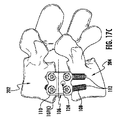
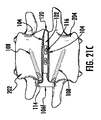
図21A〜21Dは、本開示の第7の実施形態に従うプレート106Gを有する脊椎インプラント100Dを示す。プレート106Gは2つの椎体の間の椎間腔に挿入される場合、脊椎インプラント100Gで3つのネジ108の使用を可能にするように構成される。プレート106Gを、2つの上部ボアホール110G1及び110G3及び下部ボアホール110G2で構成し得る。図21A及び21Cに示すように、上部ボアホールはボアホール110B1及び110B3と同様の特性を有し得る。具体的には、横方向中心面161Gに対して約5度の角度を有する上部ボアホール110G1及び110G3が形成され得る。プレート106Gの横方向中心面161Gに対して約20度の角度を有する下部ボアホール110G2が形成され得る。図21Bに示すように、横方向中心面161Gに対して約20度の角度を有する上部ボアホール110G1及び110G3が形成され得る。プレート106Gの横方向中心面161Gに対して約20度の角度を有する下部ボアホール110G2が形成され得る。
21A-21D illustrate a
図21A及び21Cに示すように、中心縦方向のプラントの上記ずれは、中に挿入されるネジ108を、プレート106Gの横方向中心面161Gの周りで非対称な角度でそらす一方で、図21Bにおいては、中に挿入されるネジ108を、プレート106Gの横方向中心面161Gの周りで対称な角度でそらす。下部及び上部ボアホールが横方向中心面161Gに対して5度〜20度の任意の角度でずれていてもよいことに留意されたい。
As shown in FIGS. 21A and 21C, the above-described misalignment of the central longitudinal plant causes the
図21Dに示すように、図14Cの説明に従い、上部ボアホール110G1は、それが横方向に約3度の角度でずれるように形成され得る。上部ボアホール110G3は、横方向に約1度の角度のずれを有するように形成され得る。ボアホール110G1及び110G3に挿入されるネジがそれることは、図21Dに示される。
As shown in FIG. 21D, according to the description of FIG. 14C, the
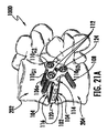
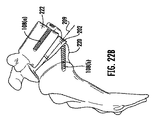
図22A〜22Cは、本開示の脊椎インプラント100の別の実施形態を示す図である。脊椎インプラント200を、2つの椎体222と220との間の椎間腔に前方に挿入し得る。例えば、脊椎インプラント200はL5−S1のために使用することができ、溶菌脊椎すべり症に対して安定性を付与する。脊椎インプラント200は椎間スペーサ本体202を含む。椎間スペーサ本体102は、一対の対向する側面204を含む。それぞれの対向する側面204は、必要に応じて、椎体の上面及び底面に摩擦係合するように提供されるピラミッド型の歯218を有する。脊椎インプラント200はまたプレート206を含む。プレート206は、20mm〜40mmの幅及び10mm〜50mmの高さを有する。プレート206は、前面及び後面で構成され、かつ椎体222及び220に最適に係合するように輪郭付けされ得る。プレート206は、少なくとも2つの上部ボアホール210及び少なくとも2つの下部ボアホール210を含んでもよく、中心線207の中心線の周りにそれぞれ配置される。
22A-22C illustrate another embodiment of the spinal implant 100 of the present disclosure. The
図22Bに示すように、上部ネジ108(a)及び下部ネジ108(b)は、インプラント200の正中線209から非対称な角度でそれてもよい。ネジ108は、椎体(例えば、L5及びS1)にプレート206を取り付け、それらの間に椎間スペーサ本体202を挿入し得る。プレート206は、外科医がプレート206のボアホール210にネジ108に挿入するストレートネジ回しを使用し得るように、ネジ108の挿入角度であるような形状となる。プレート206は、挿入及び生体力学的一貫性の容易さを提供する。プレート206は、椎間スペーサ本体202と嵌合するための領域を画定する。プレート206の後面の一部は、椎体(例えば、本体222)の壁に接触するように適合される。
As shown in FIG. 22B, the upper screw 108 (a) and the lower screw 108 (b) may deviate from the
図2Cを参照して、スペーサ本体202は、フランジ221を備え、プレート206の連結224を係合するように適合された凹部223を画定する。フランジ221と連結224との係合は、椎間スペーサ本体202に対するプレート206の横方向運動及び回転運動を防止する。ネジ(図示せず)を、スペーサ本体202にプレート206を固定するために、プレート206の中心孔に挿入し得る。下部ネジ108(b)は、インプラント200の縦方向の軸に対して角度δからとし得る。角度δは約20度であってもよい。下部ネジ108(b)のそれる角度は、インプラント200の安定性を増加させる。一般的には、ネジの頂部セットは並列であってもよく、底部セットは、複数のレベルでネジの底部(それる)セットがネジの頂部(並列)セットを妨害しないような角度であってもよい。ネジ頭の相補係止ネジ山を備えるボアホール内の係止ネジ山の前述の係合により、角度δを固定し得る。例えば、前方の手順に使用される場合、スペーサ本体202は約0.3〜0.5の長さ対幅比を有し得る。
With reference to FIG. 2C, the
本明細書に記載の本開示の多くの改変及び他の実施形態は、本開示が上記の説明に示される教示の利益を有することに属することを、当業者は念頭に置くであろう。したがって、本開示は、開示される特定の実施形態に限定されるものではなく、改変及び他の実施形態が、添付の特許請求の範囲内に含まれることが意図されることを理解されたい。本明細書において特定の用語が用いられるが、それらは、限定の目的のためではなく、一般的かつ説明的な意味でのみ使用される。 Those skilled in the art will be aware that many modifications and other embodiments of the disclosure described herein belong to the benefit of the teachings presented in the foregoing description. Accordingly, it is to be understood that this disclosure is not intended to be limited to the particular embodiments disclosed, and that modifications and other embodiments are intended to be included within the scope of the appended claims. Although specific terms are used herein, they are used in a general and descriptive sense only and not for purposes of limitation.
〔実施の態様〕
(1) 上位椎体と下位椎体との間の椎間板腔に挿入するための脊椎インプラントであって、
近位ベース部分と、遠位端と、第1の側壁と、対向する第2の側壁と、を有するスペーサ本体と、
第1の側面と、第2の側面と、前面と、後面と、前記後面から延在する一対の対向する連結フランジと、を有するプレートであって、前記プレートの横方向中心面の周りにそれぞれ配置される少なくとも1つの上部ボアホール及び少なくとも1つの下部ボアホールを形成する、プレートと、を備え、
前記プレートが、前記対向する連結フランジの機械的連結によって前記スペーサ本体に固定され、
前記少なくとも1つの上部ボアホール及び前記少なくとも1つの下部ボアホールが、前記椎間板腔内に前記脊椎インプラントを固定するために、それぞれ骨ネジを受容するように適合される、脊椎インプラント。
(2) 前記一対の対向する連結フランジのうちの少なくとも1つが、前記第1の側壁及び前記第2の側壁のうちの対応する1つの中に含まれるそれぞれの凹部内に受容されるように適合される、内向きの突出部を有する、実施態様1に記載の脊椎インプラント。
(3) 前記凹部が、それぞれの前記第1の側壁及び前記第2の側壁の一部のみに沿って延在する、実施態様2に記載の脊椎インプラント。
(4) 前記凹部が、それぞれの前記第1の側壁及び前記第2の側壁の全体に沿って延在する、実施態様2に記載のインプラント。
(5) 前記近位ベース部分が、前記第1の側壁と前記第2の側壁との間で測定されるとき、前記スペーサ本体の幅より小さい幅を有する、実施態様1に記載のインプラント。
Embodiment
(1) a spinal implant for insertion into the intervertebral disc space between the upper and lower vertebral bodies,
A spacer body having a proximal base portion, a distal end, a first sidewall and an opposing second sidewall;
A plate having a first side surface, a second side surface, a front surface, a rear surface, and a pair of opposing connecting flanges extending from the rear surface, each around a lateral center plane of the plate A plate forming at least one upper bore hole and at least one lower bore hole disposed; and
The plate is fixed to the spacer body by mechanical coupling of the opposing coupling flanges;
A spinal implant, wherein the at least one upper bore hole and the at least one lower bore hole are each adapted to receive a bone screw for securing the spinal implant within the disc space.
(2) At least one of the pair of opposing coupling flanges is adapted to be received in a respective recess included in a corresponding one of the first and second sidewalls. Embodiment 2. The spinal implant of
(3) The spinal implant according to embodiment 2, wherein the recess extends along only a part of each of the first side wall and the second side wall.
(4) The implant according to embodiment 2, wherein the recess extends along the entirety of each of the first side wall and the second side wall.
5. The implant of
(6) 前記近位ベース部分及び前記連結フランジの全幅が、合わせられると、前記スペーサ本体の前記幅にほぼ等しい、実施態様1に記載のインプラント。
(7) 前記少なくとも1つの上部ボアホール及び前記少なくとも1つの下部ボアホールが、前記プレートに対して固定された角度で前記骨ネジを係止するために、前記骨ネジのネジ付き頭部を受容するように適合される係止ネジ山を含む、実施態様1に記載の脊椎インプラント。
(8) 前記プレートの前記第1の側面が、前記椎間板腔に対して前方の位置に配置され、前記プレートの前記第2の側面が前記椎間板腔に対して後方の位置に配置される、実施態様1に記載のインプラント。
(9) 前記少なくとも1つの上部ボアホールが前記プレートの前記第1の側面に近接して配置され、前記少なくとも1つの下部ボアホールが前記プレートの前記第2の側面に配置される、実施態様8に記載のインプラント。
(10) 前記少なくとも1つの上部ボアホールが、前記少なくとも1つの上部ボアホールに挿入された第1の骨ネジが前記椎間板腔の後方側に向かう方向に角度をなすように構成され、
前記少なくとも1つの下部ボアホールが、前記少なくとも1つの下部ボアホールに挿入された第2の骨ネジが直線方向又は前記椎間板腔の前方側に向かう方向のうちの少なくとも1つの方向に角度をなすように構成される、実施態様9に記載のインプラント。
(6) The implant of
(7) The at least one upper bore hole and the at least one lower bore hole are adapted to receive a threaded head of the bone screw for locking the bone screw at a fixed angle with respect to the plate. Embodiment 2. The spinal implant of
(8) The first side surface of the plate is disposed at a front position with respect to the intervertebral disc space, and the second side surface of the plate is disposed at a rear position with respect to the intervertebral disc space. The implant according to
9. The embodiment of claim 8, wherein the at least one upper bore hole is disposed proximate to the first side of the plate and the at least one lower bore hole is disposed on the second side of the plate. Implants.
(10) The at least one upper borehole is configured such that a first bone screw inserted into the at least one upper borehole forms an angle in a direction toward the posterior side of the intervertebral disc space,
The at least one lower borehole is configured such that a second bone screw inserted into the at least one lower borehole forms an angle in at least one of a linear direction and a direction toward the anterior side of the intervertebral disc space. Embodiment 10 is an implant according to
(11) 前記少なくとも1つの上部ボアホールが、前記第1の側面に近接して形成される第1の上部ボアホールと、前記第2の側面に近接して形成される第2の上部ボアホールと、を含み、前記第1の上部ボアホール及び前記第2の上部ボアホールが、前記プレートの前記横方向中心面の周りにそれぞれ配置される、実施態様1に記載の脊椎インプラント。
(12) 前記少なくとも1つの下部ボアホールが、前記第1の側面に近接して形成される第1の下部ボアホールと、前記第2の側面に近接して形成される第2の下部ボアホールと、を含み、前記第1の下部ボアホール及び前記第2の下部ボアホールが、前記プレートの前記横方向中心面の周りにそれぞれ配置される、実施態様1に記載の脊椎インプラント。
(13) 前記少なくとも1つの下部ボアホールが、前記プレートの前記横方向中心面に対して約5度〜20度の角度で形成された中心軸を有し、前記少なくとも1つの上部ボアホールが、前記プレートの前記横方向中心面に対して約5度〜20度の角度で形成された中心軸を有する、実施態様1に記載の脊椎インプラント。
(14) 前記少なくとも1つの上部ボアホールに挿入された第1の骨ネジ及び前記下部ボアホールに挿入された第2の骨ネジが、前記横方向中心面の周りで対称な角度でそれる、実施態様13に記載の脊椎インプラント。
(15) 前記少なくとも1つの上部ボアホールに挿入された第1の骨ネジ及び前記少なくとも1つの下部ボアホールに挿入された第2の骨ネジが、前記横方向中心面の周りで非対称な角度でそれる、実施態様13に記載のインプラント。
(11) a first upper bore hole formed so that the at least one upper bore hole is close to the first side surface; and a second upper bore hole formed near the second side surface. The spinal implant according to
(12) a first lower bore hole formed so that the at least one lower bore hole is close to the first side surface; and a second lower bore hole formed near the second side surface. 2. The spinal implant according to
(13) The at least one lower borehole has a central axis formed at an angle of about 5 degrees to 20 degrees with respect to the lateral center plane of the plate, and the at least one upper borehole is the plate Embodiment 2. The spinal implant of
(14) The embodiment wherein the first bone screw inserted into the at least one upper borehole and the second bone screw inserted into the lower borehole deviate at a symmetrical angle about the lateral center plane. 14. The spinal implant according to 13.
(15) The first bone screw inserted into the at least one upper bore hole and the second bone screw inserted into the at least one lower bore hole deviate at an asymmetric angle around the lateral center plane. Embodiment 14. The implant according to embodiment 13.
(16) 前記少なくとも1つの下部ボアホールが、前記プレートの前記横方向中心面からの距離DLで配置され、前記少なくとも1つの上部ボアホールが、前記プレートの前記横方向中心面からの距離DUで配置され、DL:DUの比率が1:1である、実施態様1に記載の脊椎インプラント。
(17) 前記少なくとも1つの下部ボアホールが、前記プレートの前記横方向中心面からの距離DLで配置され、前記少なくとも1つの上部ボアホールが、前記プレートの前記横方向中心面からの距離DUで配置され、前記距離DUが、約2.75mm〜6.75mmの範囲であり、前記距離DLが、約2.75mm〜6.75mmの範囲である、実施態様1に記載の脊椎インプラント。
(18) 前記プレートが、約15mm〜23mmの範囲の高さHを有し、垂直方向の前記少なくとも1つの上部ボアホール及び前記少なくとも1つの下部ボアホールの外縁間の距離Qが、約12mm〜20mmの範囲であり得る、実施態様1に記載の脊椎インプラント。
(19) 前記スペーサ本体が、外向きに延在するピラミッド型の歯をそれぞれが有する上面側及び底面側を含む、実施態様1に記載の脊椎インプラント。
(20) 前記スペーサ本体が、そこを通って延在する中央窓を画定し、前記第1の側壁及び前記第2の側壁が、少なくとも1つの窓を画定する、実施態様1に記載の脊椎インプラント。
(16) the at least one lower borehole is arranged at a distance D L from the transverse center plane of said plate, said at least one upper borehole, at a distance D U from said transverse central plane of the plate Embodiment 2. The spinal implant of
(17) the at least one lower borehole is arranged at a distance D L from the transverse center plane of said plate, said at least one upper borehole, at a distance D U from said transverse central plane of the plate is arranged, the distance D U is in the range of about 2.75Mm~6.75Mm, the distance D L is in the range of about 2.75Mm~6.75Mm, spinal implant according to
(18) The plate has a height H in the range of about 15 mm to 23 mm, and a distance Q between the outer edges of the at least one upper bore hole and the at least one lower bore hole in the vertical direction is about 12 mm to 20 mm. Embodiment 2. The spinal implant of
(19) The spinal implant according to
The spinal implant according to
Claims (19)
近位ベース部分と、遠位端と、第1の側壁と、対向する第2の側壁と、を有するスペーサ本体と、
第1の側面と、第2の側面と、前面と、後面と、前記後面から延在する一対の対向する連結フランジと、を有するプレートであって、前記前面は、前記プレートの前記第1の側面に近接する第1の曲率半径と、前記プレートの前記第2の側面に近接する第2の曲率半径とを規定し、前記プレートが、前記プレートの横方向中心面の周りにそれぞれ配置される少なくとも1つの上部ボアホール及び少なくとも1つの下部ボアホールを形成する、プレートと、を備え、
前記プレートが、前記対向する連結フランジの機械的連結によって前記スペーサ本体に固定され、
前記少なくとも1つの上部ボアホール及び前記少なくとも1つの下部ボアホールが、前記椎間板腔内に前記脊椎インプラントを固定するために、それぞれ骨ネジを受容するように適合され、
前記一対の対向する連結フランジのうちの少なくとも1つが、前記第1の側壁及び前記第2の側壁のうちの対応する1つの中に含まれるそれぞれの凹部内に受容されるように適合される、内向きの突出部を有し、
前記プレートの高さは、前記スペーサ本体の高さよりも高い、脊椎インプラント。 A spinal implant for insertion into the disc space between the upper and lower vertebral bodies,
A spacer body having a proximal base portion, a distal end, a first sidewall and an opposing second sidewall;
A plate having a first side surface, a second side surface, a front surface, a rear surface, and a pair of opposing connecting flanges extending from the rear surface, wherein the front surface is the first side of the plate. Defining a first radius of curvature proximate to a side surface and a second radius of curvature proximate to the second side surface of the plate, the plates being respectively disposed about a lateral center plane of the plate. A plate forming at least one upper bore hole and at least one lower bore hole, and
The plate is fixed to the spacer body by mechanical coupling of the opposing coupling flanges;
The at least one upper borehole and the at least one lower borehole are each adapted to receive a bone screw to secure the spinal implant within the disc space;
At least one of the pair of opposing coupling flanges is adapted to be received in a respective recess included in a corresponding one of the first and second sidewalls; Has an inward projection,
The spinal implant, wherein the height of the plate is higher than the height of the spacer body.
前記少なくとも1つの下部ボアホールが、前記少なくとも1つの下部ボアホールに挿入された第2の骨ネジが直線方向又は前記椎間板腔の前方側に向かう方向のうちの少なくとも1つの方向に角度をなすように構成される、請求項8に記載の脊椎インプラント。 The at least one upper borehole is configured such that a first bone screw inserted into the at least one upper borehole is angled in a direction toward the posterior side of the intervertebral disc space;
The at least one lower borehole is configured such that a second bone screw inserted into the at least one lower borehole forms an angle in at least one of a linear direction and a direction toward the anterior side of the intervertebral disc space. The spinal implant of claim 8, wherein:
Applications Claiming Priority (3)
| Application Number | Priority Date | Filing Date | Title |
|---|---|---|---|
| US201261666335P | 2012-06-29 | 2012-06-29 | |
| US61/666,335 | 2012-06-29 | ||
| PCT/US2013/048973 WO2014005154A1 (en) | 2012-06-29 | 2013-07-01 | Lateral insertion spinal implant |
Publications (3)
| Publication Number | Publication Date |
|---|---|
| JP2015521919A JP2015521919A (en) | 2015-08-03 |
| JP2015521919A5 JP2015521919A5 (en) | 2016-08-18 |
| JP6419694B2 true JP6419694B2 (en) | 2018-11-07 |
Family
ID=48803610
Family Applications (1)
| Application Number | Title | Priority Date | Filing Date |
|---|---|---|---|
| JP2015520630A Active JP6419694B2 (en) | 2012-06-29 | 2013-07-01 | Transverse insertion spinal implant |
Country Status (7)
| Country | Link |
|---|---|
| US (4) | US9943417B2 (en) |
| EP (2) | EP2866745B1 (en) |
| JP (1) | JP6419694B2 (en) |
| CN (1) | CN104394804B (en) |
| AU (2) | AU2013282268A1 (en) |
| ES (1) | ES2667628T3 (en) |
| WO (1) | WO2014005154A1 (en) |
Families Citing this family (51)
| Publication number | Priority date | Publication date | Assignee | Title |
|---|---|---|---|---|
| US8328872B2 (en) | 2008-09-02 | 2012-12-11 | Globus Medical, Inc. | Intervertebral fusion implant |
| US8709083B2 (en) | 2009-06-04 | 2014-04-29 | William E. Duffield | Intervertebral fusion implant |
| US8287597B1 (en) | 2009-04-16 | 2012-10-16 | Nuvasive, Inc. | Method and apparatus for performing spine surgery |
| US9155631B2 (en) | 2010-04-08 | 2015-10-13 | Globus Medical Inc. | Intervertbral implant |
| USD685474S1 (en) | 2010-07-06 | 2013-07-02 | Tornier, Inc. | Prosthesis anchor |
| FR2978912A1 (en) | 2011-08-10 | 2013-02-15 | Tornier Inc | ANCILLARY EXTRACTION OF A PROSTHESIS |
| US10881526B2 (en) | 2011-09-16 | 2021-01-05 | Globus Medical, Inc. | Low profile plate |
| US9539109B2 (en) | 2011-09-16 | 2017-01-10 | Globus Medical, Inc. | Low profile plate |
| US9848994B2 (en) | 2011-09-16 | 2017-12-26 | Globus Medical, Inc. | Low profile plate |
| US9681959B2 (en) | 2011-09-16 | 2017-06-20 | Globus Medical, Inc. | Low profile plate |
| US9237957B2 (en) * | 2011-09-16 | 2016-01-19 | Globus Medical, Inc. | Low profile plate |
| US9149365B2 (en) * | 2013-03-05 | 2015-10-06 | Globus Medical, Inc. | Low profile plate |
| US10245155B2 (en) | 2011-09-16 | 2019-04-02 | Globus Medical, Inc. | Low profile plate |
| CN104203163B (en) * | 2011-11-17 | 2016-10-26 | 兰克斯股份有限公司 | Modular anchoring bone merges retaining frame |
| US10076364B2 (en) | 2012-06-29 | 2018-09-18 | K2M, Inc. | Minimal-profile anterior cervical plate and cage apparatus and method of using same |
| US9326861B2 (en) | 2012-08-03 | 2016-05-03 | Globus Medical, Inc. | Stabilizing joints |
| GB2507965B (en) * | 2012-11-14 | 2018-12-19 | Steris Instrument Man Services Inc | Cage assembly for tibial tuberosity advancement procedure |
| WO2014089535A1 (en) | 2012-12-07 | 2014-06-12 | Providence Medical Technology, Inc. | Apparatus and method for bone screw deployment |
| US20150112444A1 (en) * | 2013-10-18 | 2015-04-23 | Camber Spine Technologies, LLC | Sacroiliac Joint Implants and Implantation Methods |
| US10456264B2 (en) | 2014-01-24 | 2019-10-29 | Tornier, Inc. | Humeral implant anchor system |
| WO2015123693A1 (en) * | 2014-02-14 | 2015-08-20 | Spectrum Spine Ip Holdings, Llc | Cervical minimal access fusion system |
| US9642723B2 (en) | 2014-02-27 | 2017-05-09 | Alphatec Spine, Inc. | Spinal implants and insertion instruments |
| US9603718B2 (en) * | 2014-02-27 | 2017-03-28 | Alphatec Spine, Inc. | Spacer with temporary fixation plate |
| US9486327B2 (en) | 2014-05-15 | 2016-11-08 | Globus Medical, Inc. | Standalone interbody implants |
| US11160666B2 (en) | 2014-05-15 | 2021-11-02 | Globus Medical, Inc. | Laterally insertable intervertebral spinal implant |
| US9968461B2 (en) | 2014-05-15 | 2018-05-15 | Globus Medical, Inc. | Standalone interbody implants |
| US9545320B2 (en) | 2014-05-15 | 2017-01-17 | Globus Medical, Inc. | Standalone interbody implants |
| JP6687610B2 (en) * | 2014-06-30 | 2020-04-22 | グローバス メディカル インコーポレイティッド | Thin plate |
| US10363145B2 (en) * | 2015-02-23 | 2019-07-30 | Amendia, Inc. | Lateral plate and spinal implant system and method |
| KR20180028407A (en) * | 2015-05-11 | 2018-03-16 | 프로비던스 메디컬 테크놀로지, 아이엔씨. | Bone screw and implant delivery device |
| US10149710B2 (en) | 2015-05-11 | 2018-12-11 | Providence Medical Technology, Inc. | Bone screw and implant delivery device |
| US9820867B2 (en) * | 2015-05-13 | 2017-11-21 | Gil Tepper | Three column spinal fixation implants and associated surgical methods |
| US10016282B2 (en) | 2015-07-17 | 2018-07-10 | Globus Medical, Inc. | Intervertebral spacer and plate |
| US10376377B2 (en) | 2015-07-17 | 2019-08-13 | Globus Medical, Inc. | Intervertebral spacer and plate |
| US11045326B2 (en) | 2015-07-17 | 2021-06-29 | Global Medical Inc | Intervertebral spacer and plate |
| US9987144B2 (en) | 2015-07-17 | 2018-06-05 | Globus Medical, Inc. | Intervertebral spacer and plate |
| US9956087B2 (en) | 2015-07-17 | 2018-05-01 | Globus Medical, Inc | Intervertebral spacer and plate |
| CN105342680A (en) * | 2015-10-13 | 2016-02-24 | 广州聚生生物科技有限公司 | Anterior cervical interbody steel plate cage integrated internal fixing system |
| US10463499B2 (en) | 2016-03-25 | 2019-11-05 | Tornier, Inc. | Stemless shoulder implant with fixation components |
| US11129724B2 (en) | 2016-07-28 | 2021-09-28 | Howmedica Osteonics Corp. | Stemless prosthesis anchor component |
| US11766339B1 (en) | 2017-10-24 | 2023-09-26 | Omnia Medical, LLC | Multi-material multi-component spinal implant |
| US11399948B2 (en) | 2017-12-11 | 2022-08-02 | Howmedica Osteonics Corp. | Stemless prosthesis anchor components and kits |
| EP3860521B1 (en) | 2018-10-02 | 2023-11-08 | Howmedica Osteonics Corp. | Shoulder prosthesis components and assemblies |
| KR102195236B1 (en) * | 2019-06-21 | 2020-12-28 | (주)엘앤케이바이오메드 | Anterior To Psoas Fusion Cage for Lumbar Spine Surgery |
| US11596521B2 (en) * | 2019-07-03 | 2023-03-07 | DePuy Synthes Products, Inc. | Intervertebral implant for quadrupeds |
| WO2021062066A1 (en) * | 2019-09-24 | 2021-04-01 | Astura Medical Inc. | Standalone anterior cervical interbody spacer |
| JP7434538B2 (en) | 2019-10-01 | 2024-02-20 | ハウメディカ オステオニクス コーポレイション | Shoulder prosthesis components and shoulder prosthesis assemblies |
| USD951449S1 (en) | 2019-10-01 | 2022-05-10 | Howmedica Osteonics Corp. | Humeral implant |
| US11957600B2 (en) * | 2020-02-18 | 2024-04-16 | Mirus Llc | Anterior lumbar interbody fusion device with bidirectional screws |
| US11318026B2 (en) * | 2020-07-24 | 2022-05-03 | Synaptic Innovations, LLC | Implant having enhanced initial fixation force |
| WO2024006398A1 (en) * | 2022-06-29 | 2024-01-04 | Astura Medical Inc. | Spinal interbody spacer |
Family Cites Families (93)
| Publication number | Priority date | Publication date | Assignee | Title |
|---|---|---|---|---|
| US5772661A (en) | 1988-06-13 | 1998-06-30 | Michelson; Gary Karlin | Methods and instrumentation for the surgical correction of human thoracic and lumbar spinal disease from the antero-lateral aspect of the spine |
| US5534031A (en) | 1992-01-28 | 1996-07-09 | Asahi Kogaku Kogyo Kabushiki Kaisha | Prosthesis for spanning a space formed upon removal of an intervertebral disk |
| US6066175A (en) | 1993-02-16 | 2000-05-23 | Henderson; Fraser C. | Fusion stabilization chamber |
| CA2551185C (en) | 1994-03-28 | 2007-10-30 | Sdgi Holdings, Inc. | Apparatus and method for anterior spinal stabilization |
| US5860973A (en) | 1995-02-27 | 1999-01-19 | Michelson; Gary Karlin | Translateral spinal implant |
| US5968098A (en) | 1996-10-22 | 1999-10-19 | Surgical Dynamics, Inc. | Apparatus for fusing adjacent bone structures |
| DE29813139U1 (en) | 1998-07-23 | 1998-12-03 | Howmedica Gmbh | Vertebral body reconstruction system |
| DE29814174U1 (en) | 1998-08-07 | 1999-12-16 | Howmedica Gmbh | Instruments for inserting an implant into the human spine |
| US6156037A (en) | 1998-10-28 | 2000-12-05 | Sdgi Holdings, Inc. | Anterior lateral spine cage-plate fixation device and technique |
| US6342074B1 (en) | 1999-04-30 | 2002-01-29 | Nathan S. Simpson | Anterior lumbar interbody fusion implant and method for fusing adjacent vertebrae |
| AU4988700A (en) | 1999-05-05 | 2000-11-17 | Gary K. Michelson | Spinal fusion implants with opposed locking screws |
| US6432106B1 (en) | 1999-11-24 | 2002-08-13 | Depuy Acromed, Inc. | Anterior lumbar interbody fusion cage with locking plate |
| US6447545B1 (en) | 2000-07-01 | 2002-09-10 | George W. Bagby | Self-aligning bone implant |
| FR2811543B1 (en) | 2000-07-12 | 2003-07-04 | Spine Next Sa | INTERSOMATIC IMPLANT |
| DE60132796T2 (en) | 2000-10-24 | 2009-02-05 | Howmedica Osteonics Corp. | TONGUE DEVICE WITH THREAD FOR FUSIONING BENEFICIAL BONE STRUCTURES |
| US6849093B2 (en) | 2001-03-09 | 2005-02-01 | Gary K. Michelson | Expansion constraining member adapted for use with an expandable interbody spinal fusion implant and method for use thereof |
| WO2002076317A1 (en) | 2001-03-27 | 2002-10-03 | Ferree Bret A | Hinged anterior thoracic/lumbar plate |
| DE10116412C1 (en) | 2001-04-02 | 2003-01-16 | Ulrich Gmbh & Co Kg | Implant to be inserted between the vertebral body of the spine |
| FR2827156B1 (en) | 2001-07-13 | 2003-11-14 | Ldr Medical | VERTEBRAL CAGE DEVICE WITH MODULAR FASTENING |
| US6899735B2 (en) | 2002-10-02 | 2005-05-31 | Sdgi Holdings, Inc. | Modular intervertebral prosthesis system |
| US7112222B2 (en) | 2003-03-31 | 2006-09-26 | Depuy Spine, Inc. | Anterior lumbar interbody fusion cage with locking plate |
| US7819903B2 (en) * | 2003-03-31 | 2010-10-26 | Depuy Spine, Inc. | Spinal fixation plate |
| US6984234B2 (en) | 2003-04-21 | 2006-01-10 | Rsb Spine Llc | Bone plate stabilization system and method for its use |
| US8613772B2 (en) * | 2003-04-21 | 2013-12-24 | Rsb Spine Llc | Lateral mount implant device |
| US8100976B2 (en) | 2003-04-21 | 2012-01-24 | Rsb Spine Llc | Implant subsidence control |
| KR100552117B1 (en) * | 2003-07-22 | 2006-02-13 | 유앤아이 주식회사 | cervical spine fixator and driver |
| US7691146B2 (en) | 2003-11-21 | 2010-04-06 | Kyphon Sarl | Method of laterally inserting an artificial vertebral disk replacement implant with curved spacer |
| US8070816B2 (en) | 2004-03-29 | 2011-12-06 | 3Hbfm, Llc | Arthroplasty spinal prosthesis and insertion device |
| WO2006019370A1 (en) | 2004-07-15 | 2006-02-23 | Blackstone Medical, Inc. | Artificial intervertebral disc |
| WO2006047587A2 (en) | 2004-10-25 | 2006-05-04 | Alphaspine, Inc. | Expandable intervertebral spacer method and apparatus |
| US7972363B2 (en) | 2005-04-12 | 2011-07-05 | Moskowitz Ahmnon D | Bi-directional fixating/locking transvertebral body screw/intervertebral cage stand-alone constructs and posterior cervical and lumbar interarticulating joint stapling guns and devices for spinal fusion |
| US7887595B1 (en) | 2005-12-05 | 2011-02-15 | Nuvasive, Inc. | Methods and apparatus for spinal fusion |
| WO2007098288A2 (en) | 2006-02-27 | 2007-08-30 | Synthes (U.S.A.) | Intervertebral implant with fixation geometry |
| US20070225707A1 (en) * | 2006-03-22 | 2007-09-27 | Sdgi Holdings, Inc. | Orthopedic spinal devices fabricated from two or more materials |
| US7708779B2 (en) | 2006-05-01 | 2010-05-04 | Warsaw Orthopedic, Inc. | Expandable intervertebral spacers and methods of use |
| US8002837B2 (en) | 2006-05-19 | 2011-08-23 | Pioneer Surgical Technology | Spinal stabilization device and methods |
| US8100975B2 (en) | 2006-08-11 | 2012-01-24 | Warsaw Orthopedic, Inc. | Intervertebral implants with attachable flanges and methods of use |
| US7850731B2 (en) * | 2006-10-04 | 2010-12-14 | Seaspine, Inc. | Articulating spinal implant |
| US20080133014A1 (en) | 2006-12-05 | 2008-06-05 | G&L Consulting, Llc | Artificial intervertebral disc assembly and method for assembly within spine |
| US20080281425A1 (en) | 2007-02-21 | 2008-11-13 | John Thalgott | Orthopaedic Implants and Prostheses |
| US8268000B2 (en) | 2007-04-03 | 2012-09-18 | Warsaw Orthopedic, Inc. | Composite interbody spacer |
| US20080249569A1 (en) | 2007-04-03 | 2008-10-09 | Warsaw Orthopedic, Inc. | Implant Face Plates |
| US8216312B2 (en) * | 2007-05-31 | 2012-07-10 | Zimmer Spine, Inc. | Spinal interbody system and method |
| US8864832B2 (en) | 2007-06-20 | 2014-10-21 | Hh Spinal Llc | Posterior total joint replacement |
| FR2916956B1 (en) * | 2007-06-08 | 2012-12-14 | Ldr Medical | INTERSOMATIC CAGE, INTERVERTEBRAL PROSTHESIS, ANCHORING DEVICE AND IMPLANTATION INSTRUMENTATION |
| US8852280B2 (en) | 2007-09-27 | 2014-10-07 | Warsaw Orthopedic, Inc. | Intervertebral implant |
| BRPI0820172A2 (en) | 2007-11-16 | 2015-06-16 | Synthes Gmbh | Low Profile Intervertebral Implant |
| US8414651B2 (en) * | 2008-01-16 | 2013-04-09 | Aesculap Implant Systems, Llc | Dynamic interbody |
| US8377132B2 (en) | 2008-01-16 | 2013-02-19 | Aesculap Implant Systems, Llc | Standalone dynamic interbody |
| GB2457673A (en) | 2008-02-20 | 2009-08-26 | Surgicraft Ltd | Spinal implant |
| US20090210062A1 (en) | 2008-02-20 | 2009-08-20 | John Thalgott | Orthopaedic Implants and Prostheses |
| US8025678B2 (en) | 2008-03-26 | 2011-09-27 | Depuy Spine, Inc. | Interspinous process spacer having tight access offset hooks |
| FR2929106A1 (en) * | 2008-04-01 | 2009-10-02 | Biospine Implants Soc Par Acti | ADJUSTABLE BEARING BEFORE FASTENING EASILY INTEGRAL IN A VERTEBRAL BODY REPLACEMENT DEVICE |
| EP2328519B1 (en) | 2008-06-05 | 2014-12-31 | Alphatec Spine, Inc. | Modular anterior locking interbody cage |
| US8425514B2 (en) | 2008-06-25 | 2013-04-23 | Westmark Medical, Llc. | Spinal fixation device |
| US20100004747A1 (en) | 2008-07-07 | 2010-01-07 | Jin-Fu Lin | Trans-Vertebral and Intra-Vertebral Plate and Fusion Cage Device for Spinal Interbody Fusion and Method of Operation |
| US8328872B2 (en) | 2008-09-02 | 2012-12-11 | Globus Medical, Inc. | Intervertebral fusion implant |
| US8382843B2 (en) | 2008-09-02 | 2013-02-26 | Synthes Usa, Llc | Intervertebral implant with blades for connecting to adjacent vertebral bodies |
| BRPI0921486A2 (en) * | 2008-11-07 | 2019-09-10 | Synthes Gmbh | vertebral intercorporeal unit of spacer and coupled plate |
| WO2010096773A1 (en) | 2009-02-20 | 2010-08-26 | Spartan Cage Holding, Llc | Interbody fusion system with intervertebral implant retention assembly |
| PL2400931T3 (en) * | 2009-02-25 | 2016-04-29 | Spinewelding Ag | Spine stabilization device and kit for its implantation |
| WO2010107692A1 (en) * | 2009-03-16 | 2010-09-23 | Synthes Usa, Llc | System and method for stabilizing vertebrae in spine surgery through a lateral access channel |
| US8641766B2 (en) * | 2009-04-15 | 2014-02-04 | DePuy Synthes Products, LLC | Arcuate fixation member |
| FR2944692B1 (en) | 2009-04-27 | 2011-04-15 | Medicrea International | MATERIAL OF VERTEBRAL OSTEOSYNTHESIS |
| US8343223B2 (en) * | 2009-07-14 | 2013-01-01 | Life Spine, Inc. | Combined spinal interbody and plate assemblies |
| US8641765B2 (en) | 2009-08-12 | 2014-02-04 | Nabil L. Muhanna | Posterior spinal implant system |
| US20140163682A1 (en) | 2012-12-11 | 2014-06-12 | Expandable Vertebral Implant | Expandable Vertebral Implant |
| AU2010314960B2 (en) | 2009-11-09 | 2016-05-12 | Centinel Spine, Llc | Spinal implant with attachment system |
| US8894708B2 (en) * | 2009-11-09 | 2014-11-25 | Centinal Spine, Inc. | Spinal implant configured for lateral insertion |
| BR112012016296A2 (en) | 2009-12-31 | 2017-03-21 | Ldr Medical | anchorage device, intervertebral implant and implantation instrument |
| US8425576B2 (en) * | 2010-01-26 | 2013-04-23 | Westmark Medical, Llc. | Bone screw retention mechanism |
| US20110190889A1 (en) | 2010-01-29 | 2011-08-04 | Warsaw Orthopedic, Inc. | Lordotic interbody device with different sizes rails |
| US9155631B2 (en) | 2010-04-08 | 2015-10-13 | Globus Medical Inc. | Intervertbral implant |
| TW201215379A (en) | 2010-06-29 | 2012-04-16 | Synthes Gmbh | Distractible intervertebral implant |
| US20120029639A1 (en) | 2010-07-29 | 2012-02-02 | Warsaw Orthopedic, Inc. | Interbody spinal implants and insertion techniques |
| US8480747B2 (en) * | 2010-08-11 | 2013-07-09 | Warsaw Orthopedic, Inc. | Interbody spinal implants with extravertebral support plates |
| US20120078373A1 (en) * | 2010-09-23 | 2012-03-29 | Thomas Gamache | Stand alone intervertebral fusion device |
| WO2012047289A1 (en) * | 2010-10-04 | 2012-04-12 | Spinesmith Partners L.P. | Interbody fusion device and associated methods |
| US8486149B2 (en) | 2011-02-23 | 2013-07-16 | DePuy Synthes Products, LLC | Expandable interbody fusion implant |
| US9248027B2 (en) * | 2011-07-12 | 2016-02-02 | Spinesmith Partners, L.P. | Cervical implant with exterior face plate |
| US10555821B2 (en) | 2011-09-21 | 2020-02-11 | Tov Inge Vestgaarden | Method and apparatus for spinal interbody fusion including fixation or locking plate |
| US9913732B2 (en) | 2011-11-02 | 2018-03-13 | Spinesmith Partners, L.P. | Interbody fusion device with separable retention component for lateral approach and associated methods |
| US8852278B2 (en) | 2011-12-22 | 2014-10-07 | DePuy Synthes Products, LLC | Lateral cage with integrated plate |
| EP2628466B1 (en) | 2012-02-17 | 2017-04-05 | Medacta International S.A. | Intervertebral implant with improved fastening system for the fixing plate |
| FR2987256B1 (en) | 2012-02-24 | 2014-08-08 | Ldr Medical | ANCHORING DEVICE FOR INTERVERTEBRAL IMPLANT, INTERVERTEBRAL IMPLANT AND IMPLANTATION INSTRUMENTATION |
| US9271836B2 (en) | 2012-03-06 | 2016-03-01 | DePuy Synthes Products, Inc. | Nubbed plate |
| ES2770824T3 (en) | 2012-03-19 | 2020-07-03 | Amicus Design Group Llc | Intervertebral fusion prosthetic and orthopedic device with self-deploying anchors |
| US20130345813A1 (en) | 2012-06-22 | 2013-12-26 | Sheryl Frank | Dual Anchor Lateral Vertebral Body Fixation Plates |
| US9326861B2 (en) | 2012-08-03 | 2016-05-03 | Globus Medical, Inc. | Stabilizing joints |
| US10322006B2 (en) * | 2013-03-15 | 2019-06-18 | Globus Medical, Inc. | Interbody standalone intervertebral implant |
| US20170095240A9 (en) * | 2013-10-07 | 2017-04-06 | Warsaw Orthopedic, Inc. | Spinal implant system and method for lumbar and lumbosacral fusion |
| US10238502B2 (en) * | 2015-03-13 | 2019-03-26 | Xenco Medical LLC | Devices, methods, systems, and kits for the surgical treatment of cervical disc disease |
| US20180303521A1 (en) * | 2017-04-20 | 2018-10-25 | Warsaw Orthopedic, Inc | Spinal implant system and method |
-
2013
- 2013-07-01 EP EP13739320.3A patent/EP2866745B1/en active Active
- 2013-07-01 EP EP18158754.4A patent/EP3345576B1/en active Active
- 2013-07-01 JP JP2015520630A patent/JP6419694B2/en active Active
- 2013-07-01 ES ES13739320.3T patent/ES2667628T3/en active Active
- 2013-07-01 AU AU2013282268A patent/AU2013282268A1/en not_active Abandoned
- 2013-07-01 US US13/932,771 patent/US9943417B2/en active Active
- 2013-07-01 CN CN201380034687.4A patent/CN104394804B/en active Active
- 2013-07-01 WO PCT/US2013/048973 patent/WO2014005154A1/en active Application Filing
-
2018
- 2018-01-03 AU AU2018200040A patent/AU2018200040B2/en active Active
- 2018-04-16 US US15/954,321 patent/US11413159B2/en active Active
-
2022
- 2022-08-12 US US17/887,159 patent/US11717421B2/en active Active
-
2023
- 2023-05-23 US US18/322,302 patent/US20230372119A1/en active Pending
Also Published As
| Publication number | Publication date |
|---|---|
| US20180303622A1 (en) | 2018-10-25 |
| AU2013282268A1 (en) | 2015-01-22 |
| EP2866745A1 (en) | 2015-05-06 |
| EP3345576A1 (en) | 2018-07-11 |
| US20140012380A1 (en) | 2014-01-09 |
| US20230372119A1 (en) | 2023-11-23 |
| US20230034429A1 (en) | 2023-02-02 |
| AU2018200040A1 (en) | 2018-01-25 |
| US11413159B2 (en) | 2022-08-16 |
| EP2866745B1 (en) | 2018-04-04 |
| CN104394804A (en) | 2015-03-04 |
| US11717421B2 (en) | 2023-08-08 |
| US9943417B2 (en) | 2018-04-17 |
| EP3345576B1 (en) | 2020-09-30 |
| WO2014005154A1 (en) | 2014-01-03 |
| JP2015521919A (en) | 2015-08-03 |
| AU2018200040B2 (en) | 2019-09-19 |
| CN104394804B (en) | 2017-09-22 |
| ES2667628T3 (en) | 2018-05-11 |
Similar Documents
| Publication | Publication Date | Title |
|---|---|---|
| JP6419694B2 (en) | Transverse insertion spinal implant | |
| US8845737B2 (en) | Interbody spinal implants with extravertebral support plates | |
| AU2019240683B2 (en) | Lumbar-sacral screw insertion and manipulation | |
| US8343194B2 (en) | Anterior cervical staple | |
| US20120029639A1 (en) | Interbody spinal implants and insertion techniques | |
| US20230301796A1 (en) | Decoupled spacer and plate and method of installing the same | |
| US10278736B2 (en) | Methods and techniques for spinal surgery | |
| US11337734B2 (en) | Posterior spinal fixation screws | |
| US20220323117A1 (en) | Spinal facet implant and delivery tools | |
| US11389209B2 (en) | Surgical plating systems, devices, and related methods | |
| JP2017520381A (en) | Thin plate | |
| TWM444157U (en) | Interface stabilising device for facies articularis of centrum |
Legal Events
| Date | Code | Title | Description |
|---|---|---|---|
| A521 | Request for written amendment filed |
Free format text: JAPANESE INTERMEDIATE CODE: A523 Effective date: 20160627 |
|
| A621 | Written request for application examination |
Free format text: JAPANESE INTERMEDIATE CODE: A621 Effective date: 20160627 |
|
| A977 | Report on retrieval |
Free format text: JAPANESE INTERMEDIATE CODE: A971007 Effective date: 20170419 |
|
| A131 | Notification of reasons for refusal |
Free format text: JAPANESE INTERMEDIATE CODE: A131 Effective date: 20170509 |
|
| A521 | Request for written amendment filed |
Free format text: JAPANESE INTERMEDIATE CODE: A523 Effective date: 20170809 |
|
| A131 | Notification of reasons for refusal |
Free format text: JAPANESE INTERMEDIATE CODE: A131 Effective date: 20171121 |
|
| A601 | Written request for extension of time |
Free format text: JAPANESE INTERMEDIATE CODE: A601 Effective date: 20180221 |
|
| A521 | Request for written amendment filed |
Free format text: JAPANESE INTERMEDIATE CODE: A523 Effective date: 20180404 |
|
| TRDD | Decision of grant or rejection written | ||
| A01 | Written decision to grant a patent or to grant a registration (utility model) |
Free format text: JAPANESE INTERMEDIATE CODE: A01 Effective date: 20180918 |
|
| A61 | First payment of annual fees (during grant procedure) |
Free format text: JAPANESE INTERMEDIATE CODE: A61 Effective date: 20181010 |
|
| R150 | Certificate of patent or registration of utility model |
Ref document number: 6419694 Country of ref document: JP Free format text: JAPANESE INTERMEDIATE CODE: R150 |
|
| R250 | Receipt of annual fees |
Free format text: JAPANESE INTERMEDIATE CODE: R250 |
|
| R250 | Receipt of annual fees |
Free format text: JAPANESE INTERMEDIATE CODE: R250 |
|
| R250 | Receipt of annual fees |
Free format text: JAPANESE INTERMEDIATE CODE: R250 |