JP6418972B2 - Wind direction anemometer and wind direction wind speed measurement method - Google Patents
Wind direction anemometer and wind direction wind speed measurement method Download PDFInfo
- Publication number
- JP6418972B2 JP6418972B2 JP2015022356A JP2015022356A JP6418972B2 JP 6418972 B2 JP6418972 B2 JP 6418972B2 JP 2015022356 A JP2015022356 A JP 2015022356A JP 2015022356 A JP2015022356 A JP 2015022356A JP 6418972 B2 JP6418972 B2 JP 6418972B2
- Authority
- JP
- Japan
- Prior art keywords
- pressure
- wind
- pmax
- wind speed
- anemometer
- Prior art date
- Legal status (The legal status is an assumption and is not a legal conclusion. Google has not performed a legal analysis and makes no representation as to the accuracy of the status listed.)
- Active
Links
Images


Description
本発明は、空気流による圧力を検出することにより、風向及び風速を演算により求める風向風速計及び風向風速計測方法に関する。 The present invention relates to a wind direction anemometer and a wind direction wind speed measurement method for obtaining a wind direction and a wind speed by calculation by detecting a pressure due to an air flow.
風速風向計は気象状況や換気状態等を観測する目的に広く用いられており、例えば、風力発電機の建設候補地を決定する際には、様々な地点、高度で風速・風向を測定する必要がある。
一般的な風向風速計として、風杯型風速計、風車型風速計、超音波式風速計などが知られている。最近では、超音波やレーザーを用いたSODAR、LIDARにより、遠距離の計測も行われている.
Wind speed anemometers are widely used for the purpose of observing weather conditions, ventilation conditions, etc. For example, when deciding a construction site for a wind power generator, it is necessary to measure the wind speed and direction at various points and altitudes. There is.
As a general anemometer, a cup anemometer, a windmill anemometer, an ultrasonic anemometer, and the like are known. Recently, long-distance measurements have been performed by SODAR and LIDAR using ultrasonic waves and lasers.
空気流による圧力を検出することにより、風向風速を演算により求める風向風速計については、特許文献1〜3が知られている。
しかし、風杯型風速計と風車型風速計はある程度の設置スペースを必要とし、SODARやLIDARは高価で、しかも、重量があるため、設置コストが高く、設置箇所や高度を随時変えて計測を行うことは困難である。
また、空気流による圧力を検出することにより、風向風速を演算により求める風向風速計においては、圧力値が最大値となる方位を正確に特定する必要がある。
このため、特許文献1、2に記載された風向風速計においては、計測値の精度を高めるために、水平な円周に沿って多数の圧力センサを設置する必要があり、コストを要し、可搬性にも乏しい。
特許文献3に記載された風向風速計においては、1つの圧力センサを回転させることで、風向風速を演算により求めているが、微少角度毎に圧力を検出しないかぎり、正確な最大圧力を求めることができず、計測に時間を要する。
However, a cup-type anemometer and a windmill-type anemometer require a certain amount of installation space, and SODAR and LIDAR are expensive and heavy, so the installation cost is high, and the installation location and altitude can be changed at any time. It is difficult to do.
Further, in an anemometer that calculates the wind direction and wind speed by detecting the pressure due to the air flow, it is necessary to accurately specify the direction in which the pressure value becomes the maximum value.
For this reason, in the anemometers described in
In the wind direction anemometer described in
そこで、本発明は、最小限の圧力センサを用いるとともに、10°〜30°など、周方向の計測角度間隔を大きくとっても、正確な風向、風速の計測を可能にし、低コストでしかも可搬性に富む軽量コンパクトな風向風速計及び風向風速計測方法を提供することを目的としている。 Therefore, the present invention makes it possible to accurately measure the wind direction and the wind speed even when the measurement angle interval in the circumferential direction is large, such as 10 ° to 30 °, using a minimum pressure sensor, and is low in cost and portable. The object is to provide an abundant lightweight compact anemometer and wind direction anemometer.
上記の課題を解決するため、本発明の風向風速計は、空気流による圧力を検出することにより、風向及び風速を演算により求める風向風速計であって、圧力検出孔を介して空気流を導入する圧力計測管と、該圧力検出孔の圧力を検出する圧力センサとからなる圧力計と、
前記圧力計を周回駆動する駆動装置とからなり、前記圧力計測管の圧力検出孔が全方位を周回するよう前記駆動装置を駆動し、所定の方位角度毎に、前記圧力センサの計測値を記録する圧力計測結果記録手段と、前記圧力計測結果記録手段に記録された圧力センサの計測値のうち、方位、計測値が(α、P1)、(α+αr、P2)の2点と、下記の数式(1)、(2)に基づいて、前記圧力検出孔における最大圧力Pmax(U)と、この最大圧力Pmax(U)を示す際の方位αmaxを算出する算出手段と、前記算出手段により算出された最大圧力Pmax(U)及び方位、並びに、前記圧力検出孔周辺の大気圧、大気温及び湿度に基づいて、風向及び風速を演算する演算手段とを備えた。
P1=Pmax(U)・F(α)・・・・・・・(1)
P2=Pmax(U)・F(α+αr) ・・・・(2)
ただし、F(α)は、予め定められた風速に対し、前記圧力計測管の前記圧力検出孔が風に正対向する位置(α=0°)を含む、複数の周回角度(α)で取得した前記圧力センサの各計測値を、前記圧力検出孔が風に正対向する位置で得られる最大計測値で除算した規格値により予め特定した、周回角度(α)を変数とした規格値の関数である。
In order to solve the above problems, the anemometer of the present invention is an anemometer that detects the wind direction and the wind speed by detecting the pressure due to the airflow, and introduces the airflow through the pressure detection hole. A pressure gauge comprising a pressure measuring pipe that performs pressure measurement and a pressure sensor that detects the pressure in the pressure detection hole;
A driving device that drives the pressure gauge to circulate, drives the driving device so that the pressure detection hole of the pressure measuring tube circulates in all directions, and records the measurement value of the pressure sensor at every predetermined azimuth angle. Among the measured values of the pressure measurement result recording means and the pressure sensor recorded in the pressure measurement result recording means, the azimuth and the measured values are (α, P1), (α + α r , P2), Based on the mathematical formulas (1) and (2), the calculation means for calculating the maximum pressure P max (U) in the pressure detection hole and the direction α max when indicating the maximum pressure P max (U), and the calculation And a calculation means for calculating the wind direction and the wind speed based on the maximum pressure P max (U) and the direction calculated by the means, and the atmospheric pressure, the atmospheric temperature and the humidity around the pressure detection hole.
P1 = Pmax (U) · F (α) ··· (1)
P2 = P max (U) · F (α + α r ) (2)
However, F (α) is acquired at a plurality of wrapping angles (α) including a position (α = 0 °) where the pressure detection hole of the pressure measuring tube directly faces the wind with respect to a predetermined wind speed. A function of the standard value with the lap angle (α) as a variable, specified in advance by a standard value obtained by dividing each measurement value of the pressure sensor by the maximum measurement value obtained at the position where the pressure detection hole directly faces the wind It is.
また、本発明の風向風速計測方法は、空気流による圧力を検出することにより、風向及び風速を演算により求める風向風速計測方法であって、圧力検出孔を介して空気流を導入する圧力計測管と、該圧力検出孔の圧力を検出する圧力センサとからなる圧力計を、風向風速を行う地点、高度に設置する工程と、前記圧力計測管の圧力検出孔を、全方位にわたり周回させ、所定の方位角度毎に、前記圧力センサの計測値を記録する工程と、前記圧力計測結果記録手段に記録された圧力センサの計測値のうち、方位、計測値が(α、P1)、(α+αr、P2)の2点と、下記の数式(1)、(2)に基づいて、前記圧力検出孔における最大圧力Pmax(U)と、この最大圧力Pmax(U)を示す際の方位αmaxを算出する工程と、前記算出手段により算出された最大圧力Pmax(U)及び方位に基づいて、風速及び風向を演算する演算する工程とからなる。
P1=Pmax(U)・F(α)・・・・・・・(1)
P2=Pmax(U)・F(α+αr) ・・・・(2)
ただし、F(α)は、予め定められた風速に対し、前記圧力計測管の前記圧力検出孔が風に正対向する位置(α=0°)を含む、複数の周回角度(α)で取得した前記圧力センサの各計測値を、前記圧力検出孔が風に正対向する位置で得られる最大計測値で除算した規格値により予め特定した、周回角度(α)を変数とした規格値の関数である。
The wind direction and wind speed measuring method of the present invention is a wind direction and wind speed measuring method for calculating the wind direction and the wind speed by detecting the pressure due to the air flow, and a pressure measuring tube for introducing the air flow through the pressure detection hole. And a pressure gauge for detecting the pressure of the pressure detection hole, a step for installing the wind direction and wind speed at a high altitude step, and a pressure detection hole of the pressure measurement pipe circulated in all directions, Among the measured values of the pressure sensor recorded in the pressure measurement result recording means, the azimuth and the measured value are (α, P1), (α + α r , P2) and the following formulas (1) and (2), the maximum pressure P max (U) in the pressure detection hole and the orientation α when indicating the maximum pressure P max (U) a step of calculating max , and the maximum pressure calculated by the calculating means And calculating the wind speed and direction based on P max (U) and direction.
P1 = Pmax (U) · F (α) ··· (1)
P2 = P max (U) · F (α + α r ) (2)
However, F (α) is acquired at a plurality of wrapping angles (α) including a position (α = 0 °) where the pressure detection hole of the pressure measuring tube directly faces the wind with respect to a predetermined wind speed. A function of the standard value with the lap angle (α) as a variable, specified in advance by a standard value obtained by dividing each measurement value of the pressure sensor by the maximum measurement value obtained at the position where the pressure detection hole directly faces the wind It is.
本発明によれば、最小限の圧力センサを用いて、任意の2点で方位と圧力検出孔の圧力を計測するだけで、高精度の風向、風速を計測できるので、低コストでしかも可搬性に富む、風向風速計を実現することができる。
例えば、風力発電機の建設にあたっては、風車設置箇所の風況計測やアセスメントとして、さらに、建設後においては、風車周りの流れ場をモニターする必要がある。
本発明による風向風速計の軽量性、コンパクト性を活かして、無人飛行機の一つであるマルチローター(「マルチコプター」、「ドローン」と称されることもある。)に搭載することで、任意の空間領域(地点及び高度)で風向、風速を観測することができる
According to the present invention, it is possible to measure the wind direction and the wind speed with high accuracy only by measuring the azimuth and the pressure of the pressure detection hole at two arbitrary points using the minimum pressure sensor, so that it is low in cost and portable. A rich anemometer can be realized.
For example, in the construction of a wind power generator, it is necessary to monitor the flow field around the windmill as a wind condition measurement and assessment of the windmill installation site and after the construction.
By taking advantage of the lightness and compactness of the anemometer according to the present invention, it can be installed arbitrarily on a multi-rotor (sometimes called "multi-copter" or "drone"), which is one of unmanned airplanes. Wind direction and speed can be observed in the spatial region (point and altitude)
本発明の基本原理を実験例を用いて説明する。
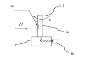
図1に示すように、圧力計1は、円筒状の圧力計測管1a、圧力センサ1bにより構成され、主流Uに対して垂直に配置されている。圧力計測管1aの上端は閉じられ、側面に設けられた、圧力検出孔1cを開口部として圧力計測管1a周りの圧力を、圧力計測管1aの開放端にパイプなどで接続された圧力センサ1bにより計測する。
圧力計測管1aは、計測地点の支持装置2に垂直に取り付けられ、ステッピングモータやサーボモータ等、回転角度を制御可能なモーターを駆動装置として軸周りに回転させる。
ただし、マルチローターに設置する場合などは、マルチローター自身の姿勢制御や振動により支持装置の姿勢が変化することを抑制する観点から、支持装置2をマルチローターに設置したジンバル上に固定し、圧力計測管1aを水平面に対し垂直にすることが好ましい。
本実験では、圧力計測管1aの外径6mm、内径3mm、圧力検出孔1cの直径0.5mmに配管された圧力センサを用いた。
The basic principle of the present invention will be described using experimental examples.
As shown in FIG. 1, the
The pressure measuring tube 1a is vertically attached to the
However, when installing on the multi-rotor, the
In this experiment, a pressure sensor provided with an outer diameter of 6 mm, an inner diameter of 3 mm of the pressure measuring tube 1a, and a diameter of 0.5 mm of the
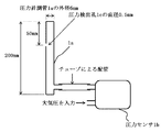
図2に、圧力計1の詳細図を示す。
外径6mm、内径3mmの円筒状の圧力計測管1aは、高さが200mmで、両端は閉塞されている。上端から50mmのところに、直径0.5mmの圧力検出孔1cが形成されている。
圧力計測管1aの下端付近には、圧力取り出し部が設けられており、圧力計測管1a内部の圧力は、チューブ等により、差圧センサ型の圧力センサ1bに導入され、大気圧との差圧が電圧値として計測される。
なお、圧力計測管1aの内部に圧力検出孔1cの直径と同等の内径を有するパイプを設け、このパイプの端部を圧力計測管1aの側壁に開口させて、このパイプの他端をチューブ等を圧力センサ1bに接続するようにしてもよい。
図3に示すように、例えば、圧力計測管1aに3点の圧力検出孔1c1、1c2、1c3を設ける場合には、圧力計測管1aの内部に、3本のパイプ1d1、1d2、1d3を設け、一端を圧力計測管1aの側壁に開口させ、他端のそれぞれを差圧センサ型圧力センサ1b1、1b2、1b3に接続する。
このとき、圧力検出孔1c1、1c2、1c3は、同一回転面内に位置しないように圧力計測管1aの高さ方向の位置が互いに異なるように配置し、同一方位時におけるそれぞれの圧力計測値に基づいて平均値を算出する。
また複数で計測する利点を生かす意味で3点の圧力検出孔を有する場合は、回転面内のそれぞれの回転角位置は0°、120°、240°に配置すれば、最速で、圧力計測管1aを120°回転させるだけで、全方位の圧力計測値を得ることができる。
FIG. 2 shows a detailed view of the
A cylindrical pressure measuring tube 1a having an outer diameter of 6 mm and an inner diameter of 3 mm has a height of 200 mm and is closed at both ends. A
Near the lower end of the pressure measuring tube 1a, a pressure take-out part is provided, and the pressure inside the pressure measuring tube 1a is introduced into the differential pressure sensor
A pipe having an inner diameter equivalent to the diameter of the
As shown in FIG. 3, for example, when three pressure detection holes 1c 1 , 1c 2 , 1c 3 are provided in the pressure measurement pipe 1a, three
At this time, the pressure detection holes 1c 1 , 1c 2 , 1c 3 are arranged so that the positions of the pressure measuring tubes 1a in the height direction are different from each other so as not to be located in the same rotation plane, and the respective pressures in the same azimuth direction. An average value is calculated based on the measured value.
In addition, in the case of having three pressure detection holes in order to take advantage of a plurality of measurement, if the respective rotation angle positions in the rotation surface are arranged at 0 °, 120 °, and 240 °, the pressure measurement tube is the fastest. By simply rotating 1a by 120 °, pressure measurements in all directions can be obtained.
ここで圧力計測管1aの外径寸法は、円筒体周りの流れが比較的安定した状態を維持する観点で設計する必要がある。その際、流れ場の状態を表す無次元数の一つであるレイノルズ数Re=U・D/νが重要となる。(U;主流速度、D;円筒体の外径、ν:動粘性係数)。
圧力計測管1a周りの流れ場に対しては、ストローハル数が一定となるレイノルズ数の範囲が5.0×10²〜3.0×10⁵程度であり、臨界レイノルズ数が4.0×10⁵程度であることから、設計レイノルズ数は、1.0×10³〜1.0×10⁵程度になるように寸法を決めるべきである。
例えば風速10m/sの場合、空気の動粘性係数を1.5×10-5m2/s、円管外径6mmとすると、レイノルズ数は4.0×103となり、風速50m/sであってもレイノルズ数は2.0×104であり、妥当といえる。
ただし、レイノルズ数の考慮だけではなく、表面の粗さ、固有振動数、剛性に加え、回転させるモーターの重さによる負荷を考慮した軽量性などの観点から材料の選択も重要である。
Here, the outer diameter of the pressure measuring tube 1a needs to be designed from the viewpoint of maintaining a relatively stable flow around the cylindrical body. At that time, the Reynolds number Re = U · D / ν, which is one of dimensionless numbers representing the state of the flow field, is important. (U: main flow velocity, D: outer diameter of cylindrical body, ν: kinematic viscosity coefficient).
For the flow field around the pressure measuring tube 1a, the Reynolds number range where the Strouhal number is constant is about 5.0 × 10 2 to 3.0 × 10 5 , and the critical Reynolds number is 4.0 ×. Since it is about 10 5 , the dimensions should be determined so that the design Reynolds number is about 1.0 × 10 3 to 1.0 × 10 5 .
For example, when the wind speed is 10 m / s, if the kinematic viscosity coefficient of air is 1.5 × 10 −5 m 2 / s and the outer diameter of the tube is 6 mm, the Reynolds number is 4.0 × 10 3 , and the wind speed is 50 m / s. Even so, the Reynolds number is 2.0 × 10 4, which is reasonable.
However, in addition to consideration of Reynolds number, selection of materials is also important from the viewpoint of lightness considering the load due to the weight of the rotating motor in addition to surface roughness, natural frequency, and rigidity.
図4は、一例として主流風速5m/sにおいて、小孔1cが主流を正対向から受けるときの回転角0°として、回転角に対する圧力分布を示す。
図の縦軸は、圧力センサ1bの出力(電圧値)表示であるが、これは小孔1cにおける圧力pと流れ場の静圧psとの差圧;P=p−psを表している。
FIG. 4 shows, as an example, a pressure distribution with respect to a rotation angle with a rotation angle of 0 ° when the
The vertical axis of the figure represents the output (voltage value) of the
図5は、小孔1cが主流を正対向から受けるときの回転角0°として、これを中心に回転角=±60°の範囲において、主流の速度U=5m/s、10m/s、15m/s、25m/sに対する圧力センサ1bの計測結果を示す。
圧力分布の最大値Pmaxは、主流方向に向かう回転角が0°のときに現れ、その値は主流速度Uが大きくなるにつれ増大することが分かる。
FIG. 5 shows a rotation angle of 0 ° when the
The maximum value P max of the pressure distribution appears when the rotation angle toward the main flow direction is 0 °, and the value increases as the main flow velocity U increases.
図6は、差圧Pの最大値が現れる0°を中心に回転角±60°の範囲において、各主流速度に対する差圧Pの圧力分布を、それぞれの風速における最大値Pmaxで除算することにより規格化している。この図から分かるように、規格化された圧力分布は、風速によらず主流方向に向かう回転角に対し、ほぼ同一の曲線上にあり、P/Pmaxが、回転角αの関数;F(α)となることが分かる。 FIG. 6 shows that the pressure distribution of the differential pressure P with respect to each mainstream speed is divided by the maximum value P max at each wind speed in the range of the rotation angle ± 60 ° around 0 ° at which the maximum value of the differential pressure P appears. It is standardized by. As can be seen from this figure, the normalized pressure distribution is on the same curve with respect to the rotation angle in the mainstream direction regardless of the wind speed, and P / P max is a function of the rotation angle α; F ( It can be seen that α).
この関数F(α)は、予め風洞実験により、次のように特定する。
上述のとおり、5m/s、10m/s、15m/s、25m/s・・・といった風速毎に、圧力センサ1bを配置した、円筒体の圧力計測管1aを、最大値が現れる回転角0°を中心に、少なくとも±60°の範囲で、例えば10°毎に、各回転角毎に圧力センサ1bにより圧力値を採取する。
例えば、最大値が現れる回転角0°±60°の範囲で、例えば10°毎にデータを採取した場合、風速毎に、13点の圧力値データP(−60°、−50°・・・0°・・・50°、60°)が得られる。
本実験では、このデータを用いて、F(α)のモデル関数を4次関数とした多項式近似を行い、最小二乗法を用いることで各係数を求め、高精度なF(α)を求めることができたが、低コスト化、軽量化、解析負荷の低減を優先する際には、2次関数など、より低次のモデル関数を用いてもよい。
This function F (α) is specified in advance as follows by a wind tunnel experiment.
As described above, the
For example, when data is collected every 10 ° in the range of the
In this experiment, using this data, polynomial approximation with the model function of F (α) as a quartic function is performed, each coefficient is obtained by using the least square method, and high-precision F (α) is obtained. However, when priority is given to cost reduction, weight reduction, and analysis load reduction, a lower order model function such as a quadratic function may be used.
なお、圧力計測管1aを回転させる際の周速度は、主流速度に比べて十分低くなければならない。また、圧力値データPを収集する周波数は、解析に十分なデータ数を確保する必要があり、回転角10°毎に取得する場合、回転速度が1回転/秒のときは、サンプリング周波数を36Hzに設定する。 In addition, the peripheral speed at the time of rotating the pressure measurement pipe | tube 1a must be low enough compared with the mainstream speed. In addition, the frequency for collecting the pressure value data P needs to secure a sufficient number of data for analysis. When the data is acquired every rotation angle of 10 °, the sampling frequency is 36 Hz when the rotation speed is 1 rotation / second. Set to.
前述のように風向に対して±60°の範囲における圧力計測管1a周りの圧力分布は、主流速度をU、回転角0°のときの圧力センサ出力をPmax(U)とすると、
P=Pmax(U)・F(α)
となる。
したがって、ある風速U、ある風向αに対して、任意の2点においては下記のように表せる。
P1=Pmax(U)・F(α) ・・・・・・・・・(1)
P2=Pmax(U)・F(α+αr)・・・・・・・(2)
ここでαrは、2点間の相対的位置を表し、既知であるとする。
As described above, the pressure distribution around the pressure measuring tube 1a in the range of ± 60 ° with respect to the wind direction is as follows. When the main flow velocity is U and the pressure sensor output at the
P = P max (U) · F (α)
It becomes.
Therefore, it can be expressed as follows at any two points with respect to a certain wind speed U and a certain wind direction α.
P 1 = P max (U) · F (α) (1)
P 2 = P max (U) · F (α + α r ) (2)
Here, α r represents a relative position between two points and is assumed to be known.
式(1)と式(2)より、
P1・F(α+αr)−P2・F(α)=0・・・・(3)
となり、この方程式を解くことでαmaxが求まる。
αmaxが求まれば、−αmaxが風向となる。
また、このαmaxを、式(1)あるいは式(2)に代入することで、Pmaxを求めることができる。
From Equation (1) and Equation (2),
P1 · F (α + αr) −P2 · F (α) = 0 (3)
Then, α max can be obtained by solving this equation.
If α max is obtained, −α max is the wind direction.
Further, P max can be obtained by substituting this α max into the formula (1) or the formula (2).
そこで、実際に風向風速を計測する場合は、例えば、真北をα=0として、圧力センサ1bの出力を記録し、例えば、F(α)を求めるときと同じように、圧力計測管1aを同速度で回転させ、Δθ=10°毎全方位にわたって、圧力センサ1bの圧力計測値をサンプリングし、計測結果記録メモリに記録する。
これらの圧力計測値のうち、最大値を特定し、このときの方位αに対し、そのn個前、あるいはn個後の圧力計測値、すなわち、αr=±n・Δθ=±n10における圧力計測値を参照圧力計測値Prefとすることで、風洞実験で特定したF(α)に両データを代入し、最大圧力値を示す風向αを算出することが可能となる。
ただし、図6から分かるように、最大値付近(−10°〜10°)は、角度毎の変化量が少なく、誤差が大きくなる可能性があるので、少なくとも1点は、この範囲からはずれた角度となるよう、αr=±20°とするなど、αとαrを選定することが好ましい。
なお、ΔθをF(α)を求めるときと同様10°としたが、10°〜30°など、計測精度を勘案して種々選択することができる。
Therefore, when actually measuring the wind direction and wind speed, for example, true north is set to α = 0, the output of the
Among these pressure measurement values, the maximum value is specified, and the pressure measurement value n times before or after the azimuth α, that is, pressure at α r = ± n · Δθ = ± n10 By setting the measured value as the reference pressure measured value Pref , it is possible to calculate the wind direction α indicating the maximum pressure value by substituting both data into F (α) specified by the wind tunnel experiment.
However, as can be seen from FIG. 6, in the vicinity of the maximum value (−10 ° to 10 °), the amount of change for each angle is small and the error may increase, so at least one point is out of this range. It is preferable to select α and α r such that α r = ± 20 ° so that an angle is obtained.
Although Δθ is set to 10 ° as in the case of obtaining F (α), various selections such as 10 ° to 30 ° can be selected in consideration of measurement accuracy.
ここで、Pmax(U)とUの関係については、ρを空気密度、速度係数をCとしたとき、次の関係にある。
U=C・(2Pmax/ρ)1/2・・・・・・・・(4)
なお、Cは速度係数であり、前述の風洞実験の際に、関数F(α)と同時に、予め求めておくことができる。
また、ρを空気密度で、Tを気温、Psを流れ場の静圧(大気圧)としたとき、次の関係にある。
ρ=[1.293/(1+0.00367T)]・Ps/1013
密度ρは、計測点における気圧、気温、湿度により決定されるため、圧力計測時にはこれらのデータを同時に取得する必要がある。
本実験では、圧力計測管1aの周辺に、大気圧センサ(絶対圧力センサ)、気温センサ、湿度センサを組み込んだが、圧力計測地点が固定されている場合には、その周辺の気象観測情報を用いてもよい。
このように、関数F(α)と速度係数Cは、事前に行う風洞実験により、予め求めておけばよく、計測時の取得データとしては、(1)少なくとも2点における圧力計測管の圧力と回転角、(2)気圧、気温、湿度、そして、(3)方位、位置座標となる。
なお、圧力センサ1bに応答遅れがある場合でも、風向、風速を計測する際、圧力計測管1aを風洞実験によりF(α)を求めるときと同速度で回転させているため、この応答遅れは相殺される。
もちろん、いずれの場合も例えば10°毎など、圧力計測管1aを間欠的に回転させ、応答遅れ分だけ、圧力計測値のサンプリングを遅らせてもよい。
Here, the relationship between P max (U) and U is as follows when ρ is the air density and the velocity coefficient is C.
U = C · (2P max / ρ) 1/2 (4)
C is a velocity coefficient, and can be obtained in advance at the same time as the function F (α) in the above-described wind tunnel experiment.
Further, when ρ is the air density, T is the air temperature, and Ps is the static pressure (atmospheric pressure) of the flow field, the following relationship is established.
ρ = [1.293 / (1 + 0.000036T)] · Ps / 1013
Since the density ρ is determined by the atmospheric pressure, the temperature, and the humidity at the measurement point, it is necessary to simultaneously acquire these data when measuring the pressure.
In this experiment, an atmospheric pressure sensor (absolute pressure sensor), an air temperature sensor, and a humidity sensor are built around the pressure measurement tube 1a. If the pressure measurement point is fixed, the weather observation information around it is used. May be.
As described above, the function F (α) and the velocity coefficient C may be obtained in advance by a wind tunnel experiment that is performed in advance, and as acquired data at the time of measurement, (1) the pressure of the pressure measuring tube at at least two points The rotation angle, (2) atmospheric pressure, temperature, humidity, and (3) azimuth and position coordinates.
Even when there is a response delay in the
Of course, in any case, for example, every 10 °, the pressure measuring tube 1a may be intermittently rotated to delay the sampling of the pressure measurement value by the response delay.
上記の基本原理を利用した風向風速計の具体的な実施例を説明する。
図7は、本実施例の全体構成を示している。
圧力計1は、円筒体の圧力計測管1a、圧力センサ1bにより構成され、この実施例では圧力計測管1aは円筒体で、上面は閉塞され、下面は開放されており、側面に圧力検出孔1cが形成されている。本実施例では、図2に示されるものを用いており、円筒体の内径を6mm、圧力検出孔1cの直径を0.5mmに設定している。また、圧力計測管1aの下方には、圧力計測管1aの外方の大気圧と、圧力検出孔1cを通過した空気流による圧力計測管1aの内部圧力との差圧を電圧値で出力する圧力センサ1bが取り付けられている。
なお、乱れ度を計測するなど、高い応答性を要求される場合には、この小孔1cに圧力センサ1bを直付けし、比較的低い応答性で十分な場合は、図2のように、圧力計測管1aの開放端からチューブなどを介して圧力センサ1bに導く。
A specific embodiment of an anemometer utilizing the above basic principle will be described.
FIG. 7 shows the overall configuration of this embodiment.
The
In addition, when high responsiveness is required, such as measuring the degree of turbulence, the
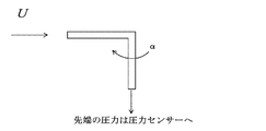
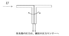
なお、圧力計測管1aとしては、円筒型のほか、図8に示すように、先端が水平方向に開口するL字型パイプ、さらに、図9に示すように、このL字型パイプを2本組み合わせて、水平部をT字状に配置したもの、一定角度毎に配置したもの等を採用することができる。 As the pressure measuring pipe 1a, in addition to the cylindrical type, as shown in FIG. 8, an L-shaped pipe whose tip is opened in the horizontal direction, and two L-shaped pipes as shown in FIG. In combination, a horizontal portion arranged in a T-shape, a one arranged at a certain angle, or the like can be adopted.
圧力計1は、支持装置2上面の回転盤2aに取り付けられており、圧力検出孔1cを360°にわたり周回させるもので、本実施例では、基準位置にある圧力検出孔1cが真北(α=0)を向くよう、地上に設置されている。なお、支持装置2を支持する支持台2bは、上下方向に伸縮調整可能な脚により、風向・風速の観測地点の地上からの高さを調整できるようにしてもよい。なお、2bは支持装置2の支持台で、高さ調整装置を備えるようにしてもよい。
The
回転盤2aを周回させる駆動装置として、ステッピングモータやサーボモータを用い、後述する演算制御装置3からの指令により、基準位置(真北;θ=0°)から、圧力計1を一定速度で周回させ、基準位置からの一定の回転角度毎に周回角度、すなわち方位θを演算制御装置3に出力する。
本実施例の場合、1本の円筒体型圧力計測管1aを用いているため、回転盤2aを例えば、10°ずつ、360°周回させる。
なお、2本の圧力計測管を直線上に配列し、180°異なる位置で同時に圧力を検出する場合は、回転盤2aを180°、120°毎に3本の圧力計測管を配列する場合は120°回転させ、それぞれ10°毎に圧力センサ1bの圧力計測値をサンプリングするようにすればよい。
A stepping motor or servo motor is used as a driving device for rotating the
In the case of the present embodiment, since one cylindrical pressure measuring tube 1a is used, the
When two pressure measuring tubes are arranged on a straight line and pressure is simultaneously detected at different positions by 180 °, when the
演算制御装置3は、風向風速の計測開始指令を受けると、圧力検出孔1cが前述の基準位置となるよう初期調整を行い図4に示すように、真北(θ°=0)における圧力センサ1bの計測を行い、方位(θ=0°;真北N)とともに、圧力センサ1bの計測値P(0)を計測結果記録メモリ3aに記録する。
When the
次に、支持装置2の回転盤2aを周回させる駆動モーターに指令を出力し、一定回転速度で圧力計測管1aを回転させ、その回転角を参照しながら、設定角度毎のタイミングで圧力センサ1bの計測値P(Δθ)、P(2Δθ)、P(3Δθ)・・・取得し、計測結果記録メモリ3aに、方位角毎に記録する。
例えば、圧力計測管1aを1回転/秒で回転駆動し、10°毎に圧力センサ1bの計測値を記録する場合には、36Hzのサンプリング周波数が必要となる。
なお、圧力計測管1aを周回に伴う周速は、外径6mmの円柱を1回転/秒の場合、風速に対し、きわめて低い速度で、周速の影響を無視することができる。
Next, a command is output to a drive motor that circulates the
For example, when the pressure measuring tube 1a is rotationally driven at 1 rotation / second and the measurement value of the
In addition, the peripheral speed accompanying the circulation of the pressure measuring tube 1a is extremely low with respect to the wind speed when a cylinder having an outer diameter of 6 mm is 1 rotation / second, and the influence of the peripheral speed can be ignored.
この計測を、θが360°となるまで繰り返すことで、計測結果記録メモリ3aには、α=0°から350°までの圧力センサ3aの計測値が記録される。
なお、このような計測結果記録を、何回か連続して繰り返し、後述する風向・風速を演算する際、これらの平均値を用いるようにしてもよい。
By repeating this measurement until θ reaches 360 °, measurement values of the
Such measurement result recording may be repeated several times in succession, and an average value of these may be used when calculating a wind direction and a wind speed to be described later.
前述のように、圧力計1に関しては、予め風洞実験により、既定の風速(5m/s、10m/s、15m/s、25m/s・・・)に対し、圧力検出孔1cを360°周回させ、10°毎に得られた圧力センサの検出値;P(0)、P(10°)、P(20°)・・・P(350°)を、正対向する際に得られる最大値(Pmax)であるP(0)で除算することにより、規格化(1、P(10)/P(0)、P(20)/P(0)・・・P(350)/P(10)に基づいて、風向(α)に対する規格値の関数、F(α)が定められている。
As described above, with respect to the
変換された風速値から最大値(P’max、α’max)を特定し、この最大値の前後の参照風速値(Pref、α’max±αr)を特定する。
両データを式(2)、(3)に代入することで、最大圧力計測値Pmaxを示す風向αmaxが算出され、このαmaxにより、最大圧力計測値Pmaxを算出することができる。
こうして、最大圧力計測値Pmaxが特定されれば、前述の式(4)により、風速を換算することが可能となる。算出された風速データは、出力装置4を介して、ディスプレイに表示されるとともに、計測日時とともに記録され、風向風速計測結果としてプリンタなどに出力できるようにする。
A maximum value (P ′ max , α ′ max ) is specified from the converted wind speed value, and a reference wind speed value (P ref , α ′ max ± αr ) before and after the maximum value is specified.
Both data to the equation (2), by substituting the (3), the wind direction alpha max indicating the maximum pressure measured value P max is calculated by the alpha max, it is possible to calculate the maximum pressure measured value P max.
Thus, if the maximum pressure measurement value P max is specified, the wind speed can be converted by the above-described equation (4). The calculated wind speed data is displayed on the display via the output device 4 and is recorded together with the measurement date and time so that it can be output to a printer or the like as a wind direction wind speed measurement result.
この実施例では、支持装置2を支持台2bで支持する場合を示したが、支持装置2をマルチコプターに搭載し、マルチローターからの高さ情報、位置情報と連動させて、圧力計測値をメモリに記録し、マルチローターからメモリを回収し、記録したデータに基づいて、風向風速を算出するようにしてもよい。この際、支持装置は、マルチローターに設置されたジンバル上に固定することにより、マルチローター自身の姿勢制御や振動の影響を抑制する。
In this embodiment, the case where the
以上説明したように、本発明によれば、低コストでしかも可搬性に富む、風向風速計を実現することができ、風車設置箇所の風況計測のみならず、交通機関の安全運行を確保するための風況計測など、様々な分野で広く採用されることが期待される。 As described above, according to the present invention, it is possible to realize an anemometer that is low in cost and rich in portability, and not only measures wind conditions at wind turbine installation locations but also ensures safe operation of transportation facilities. It is expected to be widely adopted in various fields such as wind condition measurement.
1:圧力計
1a:圧力計測管
1b:圧力センサ
1c:圧力検出孔(小孔)
2:支持装置
2a;回転盤
2b:支持台
3:演算制御装置
3a:計測結果記録メモリ
4:出力装置
1: Pressure gauge 1a:
2:
Claims (9)
圧力検出孔を介して風による空気流を導入する圧力計測管と、該導入された空気流の圧力を検出する圧力センサとからなる圧力計と、
前記圧力計を周回駆動する駆動装置と、
前記駆動装置により前記圧力検出孔が全方位を周回するよう駆動して、方位角の所定角度αr毎に、前記圧力センサの計測値を記録する圧力計測結果記録手段と、
前記圧力計測結果記録手段に記録された圧力センサの計測値のうち2点の方位角θ1、θ2のそれぞれに対応する計測値P1、P2と、下記の数式(1)、(2)に基づいて、前記風による最大圧力Pmax(U)およびPmax(U)を示す方位角αmaxを算出する算出手段と、
前記算出手段により算出された最大圧力Pmax(U)及び方位角αmaxに基づいて、前記風の風速及び風向を求める演算手段と、を備える、前記風向風速計;
P1=Pmax(U)・F(θ1) ・・・・・・・(1)
P2=Pmax(U)・F(θ2) ・・・・・・・(2)
ただし、F(θ)は、予め定められた風速に対し、前記圧力検出孔が風に正対向する位置を含む複数の周回角度θで取得した前記圧力センサの各計測値を、前記圧力検出孔が風に正対向する位置で得られる最大計測値で除算した規格化関数であり、θの関数である。 An anemometer that detects the wind direction and the wind speed by calculating the pressure due to the air flow,
A pressure gauge that includes a pressure measuring pipe that introduces an air flow by wind through the pressure detection hole, and a pressure sensor that detects the pressure of the introduced air flow;
A driving device for driving the pressure gauge around,
A pressure measurement result recording means for driving the pressure detection hole to circulate in all directions by the driving device, and recording the measurement value of the pressure sensor for each predetermined angle αr of the azimuth;
Based on the measured values P1 and P2 corresponding to the two azimuth angles θ1 and θ2 among the measured values of the pressure sensor recorded in the pressure measurement result recording means, and the following mathematical formulas (1) and (2): Calculating means for calculating an azimuth angle αmax indicating the maximum pressures Pmax (U) and Pmax (U) by the wind;
The wind direction anemometer, comprising: calculation means for obtaining the wind speed and direction of the wind based on the maximum pressure Pmax (U) and the azimuth angle αmax calculated by the calculation means;
P1 = Pmax (U) ・ F (θ1) (1)
P2 = Pmax (U) ・ F (θ2) (2)
However, F (θ) is the measured value of the pressure sensor acquired at a plurality of turning angles θ including a position where the pressure detection hole directly faces the wind with respect to a predetermined wind speed. Is a normalized function divided by the maximum measured value obtained at a position directly opposite the wind, and is a function of θ.
前記マルチローターは前記圧力計および前記駆動装置を支持するジンバルを有し、
前記マルチローターの位置情報および高度情報を前記圧力計測結果記録手段にさらに記録する、請求項1〜5のうちいずれか一項に記載の風向風速計。 The pressure gauge and the driving device are mounted on a multi-rotor,
The multi-rotor has a gimbal that supports the pressure gauge and the driving device,
The anemometer as claimed in any one of claims 1 to 5, wherein the multirotor position information and altitude information are further recorded in the pressure measurement result recording means.
圧力検出孔を全方位にわたり周回させ、方位角の所定角度αr毎に、該圧力検出孔を介して風による空気流を導入し、該導入された空気流の圧力を圧力センサによって検出し、その計測値を記録する工程と、
前記圧力計測結果記録手段に記録された圧力センサの計測値のうち2点の方位角θ1、θ2のそれぞれに対応する計測値P1、P2と、下記の数式(1)、(2)に基づいて、前記風による最大圧力Pmax(U)およびPmax(U)を示す方位角αmaxを算出する工程と、
前記算出手段により算出された最大圧力Pmax(U)および方位角αmaxに基づいて、前記風の風速および風向を求める工程と、を含み、
前記記録する工程の前に、予め定められた風速に対し、前記圧力検出孔が風に正対向する位置を含む複数の周回角度θで前記圧力センサの計測値を取得し、該圧力検出孔が風に正対向する位置で得られる最大計測値で除算した規格化関数F(θ)を求める工程をさらに含む、前記風向風速計測方法;
P1=Pmax(U)・F(θ1) ・・・・・・・(1)
P2=Pmax(U)・F(θ2) ・・・・・・・(2)
ただし、F(θ)はθの関数である。 A wind direction and wind speed measurement method for calculating a wind direction and a wind speed by detecting a pressure caused by an air flow,
The pressure detection hole is circulated in all directions, an air flow by wind is introduced through the pressure detection hole at every predetermined angle αr of the azimuth angle, and the pressure of the introduced air flow is detected by a pressure sensor. Recording the measured value;
Based on the measured values P1 and P2 corresponding to the two azimuth angles θ1 and θ2 among the measured values of the pressure sensor recorded in the pressure measurement result recording means, and the following mathematical formulas (1) and (2): Calculating the azimuth angle αmax indicating the maximum pressures Pmax (U) and Pmax (U) by the wind;
Obtaining the wind speed and direction of the wind based on the maximum pressure Pmax (U) and the azimuth angle αmax calculated by the calculation means,
Prior to the recording step, the measurement values of the pressure sensor are acquired at a plurality of rotation angles θ including a position where the pressure detection hole directly faces the wind with respect to a predetermined wind speed, and the pressure detection hole The wind direction and wind speed measuring method further comprising the step of obtaining a normalization function F (θ) divided by the maximum measured value obtained at a position directly opposite to the wind;
P1 = Pmax (U) ・ F (θ1) (1)
P2 = Pmax (U) ・ F (θ2) (2)
However, F (θ) is a function of θ.
Priority Applications (1)
| Application Number | Priority Date | Filing Date | Title |
|---|---|---|---|
| JP2015022356A JP6418972B2 (en) | 2015-02-06 | 2015-02-06 | Wind direction anemometer and wind direction wind speed measurement method |
Applications Claiming Priority (1)
| Application Number | Priority Date | Filing Date | Title |
|---|---|---|---|
| JP2015022356A JP6418972B2 (en) | 2015-02-06 | 2015-02-06 | Wind direction anemometer and wind direction wind speed measurement method |
Publications (3)
| Publication Number | Publication Date |
|---|---|
| JP2016145734A JP2016145734A (en) | 2016-08-12 |
| JP2016145734A5 JP2016145734A5 (en) | 2018-06-28 |
| JP6418972B2 true JP6418972B2 (en) | 2018-11-07 |
Family
ID=56685681
Family Applications (1)
| Application Number | Title | Priority Date | Filing Date |
|---|---|---|---|
| JP2015022356A Active JP6418972B2 (en) | 2015-02-06 | 2015-02-06 | Wind direction anemometer and wind direction wind speed measurement method |
Country Status (1)
| Country | Link |
|---|---|
| JP (1) | JP6418972B2 (en) |
Families Citing this family (6)
| Publication number | Priority date | Publication date | Assignee | Title |
|---|---|---|---|---|
| JP6829108B2 (en) * | 2017-02-24 | 2021-02-10 | セイコーインスツル株式会社 | Altimeter and altitude detection method |
| KR101948043B1 (en) * | 2017-05-16 | 2019-02-14 | 동의대학교 산학협력단 | Wind direction-sensing umbrella and method for operating the same |
| CN109444460B (en) * | 2018-10-17 | 2021-01-01 | 合肥凌山新能源科技有限公司 | Wind direction measuring device and method for wind power generation |
| JP7180450B2 (en) * | 2019-02-28 | 2022-11-30 | 富士通株式会社 | Aircraft and control method for aircraft |
| CN110031648B (en) * | 2019-04-10 | 2023-12-29 | 绍兴文理学院元培学院 | Pore wind speed measuring device of porous medium of granule |
| CN113238074B (en) * | 2021-05-18 | 2023-01-06 | 贵州电网有限责任公司 | Pitot tube wind speed and direction measuring method based on sextant method |
Family Cites Families (3)
| Publication number | Priority date | Publication date | Assignee | Title |
|---|---|---|---|---|
| DE3544144A1 (en) * | 1985-12-13 | 1987-06-25 | Eduard Prof Dr Ing Igenbergs | METHOD AND DEVICE FOR DETERMINING A FLOW ANGLE ON VEHICLES |
| JP5713231B2 (en) * | 2010-10-14 | 2015-05-07 | 独立行政法人国立高等専門学校機構 | Flying object |
| JP5656316B1 (en) * | 2014-04-17 | 2015-01-21 | 善郎 水野 | System including a marker device and method using the same |
-
2015
- 2015-02-06 JP JP2015022356A patent/JP6418972B2/en active Active
Also Published As
| Publication number | Publication date |
|---|---|
| JP2016145734A (en) | 2016-08-12 |
Similar Documents
| Publication | Publication Date | Title |
|---|---|---|
| JP6418972B2 (en) | Wind direction anemometer and wind direction wind speed measurement method | |
| ES2296143T3 (en) | PROCEDURE AND APPLIANCE TO DETERMINE THE SPEED AND WIND DIRECTION EXPERIENCED BY A WIND BAND. | |
| Wan et al. | Measurement of the velocity field in a simulated tornado-like vortex using a three-dimensional velocity probe | |
| US8093738B2 (en) | Method for wind turbine yaw control | |
| CN203053472U (en) | Tool for measuring pressure and velocity of eddy flow field | |
| CN107085126A (en) | A kind of LDV calibrating installation measured based on Dynamic Radius | |
| US11592838B2 (en) | Velocity sensing for aircraft | |
| JP2016145734A5 (en) | ||
| CN106643576A (en) | Non-concentricity measurement method and non-concentricity measurement device | |
| RU2464579C2 (en) | Apparatus and method of measuring speed and direction of flow of gaseous fluid medium | |
| US7949481B2 (en) | Self-orienting embedded in-situ flux system | |
| CN102305872B (en) | Superconductive rotor turning axle deviation angle speed measuring apparatus | |
| CN106885922B (en) | A kind of wind vane calibrating installation and method for wind power generating set | |
| CN103234498A (en) | Method and device for measuring intersection degrees of precision centrifugal machine | |
| JP7112194B2 (en) | Measurement system and measurement method using drone | |
| US10371713B2 (en) | Measurement of the flow velocity and the flow direction of gases and liquids | |
| Town et al. | Total pressure correction of a sub-miniature five-hole probe in areas of pressure gradients | |
| KR100910391B1 (en) | Wind detecting sensor | |
| Hickman et al. | Development of Low Cost, Rapid Sampling Atmospheric Data Collection System: Part 1--Fully Additive-Manufactured Multi-Hole Prob | |
| KR101746437B1 (en) | Two-dimensional vane using bimorphs | |
| Knowlen et al. | Kirsten Wind Tunnel Flow Quality Assessment: 2018 | |
| UA69551A (en) | Method for calibrating anemometer and a device for the realization of the method | |
| Br et al. | Fast Traveling Pneumatic Probes for Turbomachinery Applications | |
| CN116106575A (en) | Wind speed testing device and wind speed testing method | |
| Halleaux et al. | The Michigan Prandtl System: An Instrument for Accurate Pressure Measurements in Convective Vortices |
Legal Events
| Date | Code | Title | Description |
|---|---|---|---|
| A621 | Written request for application examination |
Free format text: JAPANESE INTERMEDIATE CODE: A621 Effective date: 20171225 |
|
| A521 | Request for written amendment filed |
Free format text: JAPANESE INTERMEDIATE CODE: A523 Effective date: 20180313 |
|
| A131 | Notification of reasons for refusal |
Free format text: JAPANESE INTERMEDIATE CODE: A131 Effective date: 20180911 |
|
| A521 | Request for written amendment filed |
Free format text: JAPANESE INTERMEDIATE CODE: A523 Effective date: 20180914 |
|
| A977 | Report on retrieval |
Free format text: JAPANESE INTERMEDIATE CODE: A971007 Effective date: 20180912 |
|
| TRDD | Decision of grant or rejection written | ||
| A01 | Written decision to grant a patent or to grant a registration (utility model) |
Free format text: JAPANESE INTERMEDIATE CODE: A01 Effective date: 20181009 |
|
| A61 | First payment of annual fees (during grant procedure) |
Free format text: JAPANESE INTERMEDIATE CODE: A61 Effective date: 20181009 |
|
| R150 | Certificate of patent or registration of utility model |
Ref document number: 6418972 Country of ref document: JP Free format text: JAPANESE INTERMEDIATE CODE: R150 |
|
| R250 | Receipt of annual fees |
Free format text: JAPANESE INTERMEDIATE CODE: R250 |
|
| R250 | Receipt of annual fees |
Free format text: JAPANESE INTERMEDIATE CODE: R250 |
|
| R250 | Receipt of annual fees |
Free format text: JAPANESE INTERMEDIATE CODE: R250 |