JP6415093B2 - Image processing apparatus, image processing method, and program - Google Patents
Image processing apparatus, image processing method, and program Download PDFInfo
- Publication number
- JP6415093B2 JP6415093B2 JP2014091875A JP2014091875A JP6415093B2 JP 6415093 B2 JP6415093 B2 JP 6415093B2 JP 2014091875 A JP2014091875 A JP 2014091875A JP 2014091875 A JP2014091875 A JP 2014091875A JP 6415093 B2 JP6415093 B2 JP 6415093B2
- Authority
- JP
- Japan
- Prior art keywords
- interpolation
- image data
- pixel
- image
- unit
- Prior art date
- Legal status (The legal status is an assumption and is not a legal conclusion. Google has not performed a legal analysis and makes no representation as to the accuracy of the status listed.)
- Active
Links
Images


Classifications
-
- G—PHYSICS
- G06—COMPUTING; CALCULATING OR COUNTING
- G06T—IMAGE DATA PROCESSING OR GENERATION, IN GENERAL
- G06T3/00—Geometric image transformation in the plane of the image
- G06T3/40—Scaling the whole image or part thereof
- G06T3/4015—Demosaicing, e.g. colour filter array [CFA], Bayer pattern
-
- H—ELECTRICITY
- H04—ELECTRIC COMMUNICATION TECHNIQUE
- H04N—PICTORIAL COMMUNICATION, e.g. TELEVISION
- H04N23/00—Cameras or camera modules comprising electronic image sensors; Control thereof
- H04N23/10—Cameras or camera modules comprising electronic image sensors; Control thereof for generating image signals from different wavelengths
- H04N23/12—Cameras or camera modules comprising electronic image sensors; Control thereof for generating image signals from different wavelengths with one sensor only
-
- H—ELECTRICITY
- H04—ELECTRIC COMMUNICATION TECHNIQUE
- H04N—PICTORIAL COMMUNICATION, e.g. TELEVISION
- H04N23/00—Cameras or camera modules comprising electronic image sensors; Control thereof
- H04N23/80—Camera processing pipelines; Components thereof
- H04N23/84—Camera processing pipelines; Components thereof for processing colour signals
- H04N23/843—Demosaicing, e.g. interpolating colour pixel values
-
- H—ELECTRICITY
- H04—ELECTRIC COMMUNICATION TECHNIQUE
- H04N—PICTORIAL COMMUNICATION, e.g. TELEVISION
- H04N25/00—Circuitry of solid-state image sensors [SSIS]; Control thereof
- H04N25/10—Circuitry of solid-state image sensors [SSIS]; Control thereof for transforming different wavelengths into image signals
- H04N25/11—Arrangement of colour filter arrays [CFA]; Filter mosaics
- H04N25/13—Arrangement of colour filter arrays [CFA]; Filter mosaics characterised by the spectral characteristics of the filter elements
- H04N25/134—Arrangement of colour filter arrays [CFA]; Filter mosaics characterised by the spectral characteristics of the filter elements based on three different wavelength filter elements
Description
本発明は、画像処理装置、画像処理方法、及びプログラムに関し、カラー画像信号に係る補間技術に関する。 The present invention relates to an image processing device, an image processing method, and a program, and to an interpolation technique related to a color image signal.
従来、カラー撮像センサにおいては、図17に示すようなベイヤー配列のカラーフィルタが用いられている。カラーフィルタとしては、赤(R:Red)、緑(G:Green)、青(B:Blue)の3原色フィルタや、シアン(Cyan)、マゼンタ(Magenta)、黄(Yellow)の3つの補色フィルタが用いられている。 Conventionally, in a color imaging sensor, a Bayer array color filter as shown in FIG. 17 is used. As color filters, three primary color filters of red (R: Red), green (G: Green), and blue (B: Blue), and three complementary color filters of cyan (Cyan), magenta (Magenta), and yellow (Yellow) Is used.
しかし、ベイヤー配列のカラーフィルタでは、各画素において1つの信号しか得られないので、各画素において欠落している他の2色のカラー信号をデモザイキング(補間)する処理が行われる。デモザイキング法としては、バイリニアやバイキュービック補間が知られている。バイリニアやバイキュービック補間では、低周波成分を多く含む画像等では良好な補間結果が得られるが、高周波成分を含む画像には偽解像や偽色(色モアレ)と呼ばれる実際の被写体には存在しない線や色を発生させてしまう。これらの偽解像や偽色は、被写体像が本来有しているエッジ方向とは異なる方向の画素を用いてデモザイキングすることにより発生する。 However, since the Bayer color filter can obtain only one signal in each pixel, a process of demosaicing (interpolating) the other two color signals missing in each pixel is performed. Bilinear and bicubic interpolation are known as demosaicing methods. Bilinear and bicubic interpolation provide good interpolation results for images that contain a lot of low-frequency components, but images that contain high-frequency components exist in actual subjects called false resolution and false color (color moire). Do not generate lines and colors. These false resolutions and false colors are generated by demosaicing using pixels in a direction different from the edge direction that the subject image originally has.
そこで、被写体像が本来有しているエッジ方向に沿った画素を用いてデモザイキングする方法が提案されている。エッジ方向に沿った画素を用いるデモザイキング法は、2つの方法に大別でき、特許文献1ではエッジ方向を周囲の画素を使用して判別し、エッジを跨ぐような補間をせずエッジに沿うように補間する方法が提案されている。また、特許文献1では、まず方向毎に補間を行って数種類の補間結果を生成し、その後どの方向で補間した結果が適切かを判定し選択する補間方法が提案されている。補間方向の適切性の判断には、補間対象画素を含めた周辺画素からその近辺の均質性を示す評価値を導入し、均質性の高い方向がエッジ方向と判定して選択する補間方法が提案されている。
Therefore, a method of demosaicing using pixels along the edge direction inherent to the subject image has been proposed. The demosaicing method using pixels along the edge direction can be broadly divided into two methods. In
しかしながら、特許文献1に記載の方法は、撮像センサの画素ピッチと被写体の細かなピッチとが一致するような解像限界付近では、均質性を示す評価値の誤算出による補間ミスを起こして偽解像が発生することが懸念される。本発明は、このような事情に鑑みてなされたものであり、画像信号に対するデモザイキング処理を高精度に行えるようにすることを目的とする。 However, the method described in Japanese Patent Laid-Open No. 2004-228688 causes an interpolation error due to erroneous calculation of an evaluation value indicating homogeneity near the resolution limit where the pixel pitch of the image sensor matches the fine pitch of the subject. There is concern about the occurrence of resolution. The present invention has been made in view of such circumstances, and an object thereof is to perform a demosaicing process on an image signal with high accuracy.
本発明に係る画像処理装置は、複数色のカラーフィルタを備えた撮像素子により被写体像を反映した光学像を光電変換して得られた、各画素が前記複数色のカラーフィルタのいずれかの色に対応する画像データを有するモザイク画像データに対し、複数の規定方向について、各画素において欠落している色の画像データを補間するために、各画素の周辺の前記規定方向の画素に係る画像データを用いてそれぞれ補間処理を行う第1の補間手段と、前記第1の補間手段により前記補間処理が施された各規定方向の画像データの評価を行う評価手段と、前記モザイク画像データに対し、各画素において欠落している色の画像データを補間するために、各画素の周辺の画素に係る画像データを用いて方向を持たない補間処理を行う第2の補間手段と、前記モザイク画像データに対し、各画素において欠落している色の画像データを補間するために、エッジ成分を保存する補間処理を行う第3の補間手段と、前記第3の補間手段により前記補間処理が施された画像データから彩度を検出する彩度検出手段と、前記彩度検出手段により検出された彩度に基づいて、画素毎に偽解像が発生する領域であるか否かを判定する判定手段と、前記判定手段によって偽解像が発生する領域であると判定された画素では、前記第2の補間手段の補間処理によって生成された画像データを選択して補間後の前記複数色の画像データを生成し、前記判定手段によって偽解像が発生する領域ではないと判定された画素では、前記評価手段による評価結果に基づいて、前記第1の補間手段の補間処理によって生成された各規定方向の画像データのいずれかを選択して補間後の前記複数色の画像データを生成する画像生成手段とを有することを特徴とする。 The image processing apparatus according to the present invention is such that each pixel is one of the color filters of the plurality of colors obtained by photoelectrically converting an optical image reflecting a subject image by an image sensor having a plurality of color filters. In order to interpolate image data of missing colors in each pixel with respect to a plurality of prescribed directions with respect to mosaic image data having image data corresponding to, image data relating to pixels in the prescribed direction around each pixel First interpolation means for performing interpolation processing using each of the above, evaluation means for evaluating image data in each prescribed direction subjected to the interpolation processing by the first interpolation means, and the mosaic image data, Second interpolation means for performing interpolation processing having no direction using image data relating to pixels around each pixel in order to interpolate image data of a missing color in each pixel; To said mosaic image data, to interpolate the image data of the color missing in each pixel, the interpolation process and the third interpolation means for performing interpolation processing for storing the edge components, by the third interpolation means Saturation detection means for detecting the saturation from the image data that has been subjected to the determination, and whether or not it is a region where false resolution occurs for each pixel based on the saturation detected by the saturation detection means And the plurality of colors after the interpolation by selecting the image data generated by the interpolation process of the second interpolation unit in the pixel determined to be a region where false resolution occurs by the determination unit the image data generated in the pixel of spurious resolution is determined not to be a region generated by the determination means, based on the evaluation results by the evaluation unit, it is generated by interpolation of the first interpolation means And having an image generating means for generating image data of the plurality of colors after the interpolation by selecting one of the image data in each specified direction.
本発明によれば、エッジ成分を保存する補間処理により得られた画像データから検出された彩度に基づいて、画素毎に偽解像が発生する領域であるか判定する。これにより、偽解像が発生する箇所の検出を精度良く行い、デモザイキング処理で発生する偽解像をより適切に補正することができ、画像信号に対するデモザイキング処理を高精度に行うことが可能になる。 According to the present invention, determines based on the saturation detected from image data obtained by interpolation of the edge component preserved, it is an area in which false resolution occurs for each pixel. As a result, it is possible to accurately detect the location where the false resolution occurs, correct the false resolution generated in the demosaicing process more appropriately, and perform the demosaicing process on the image signal with high accuracy. become.
以下、本発明の実施形態を図面に基づいて説明する。 Hereinafter, embodiments of the present invention will be described with reference to the drawings.
(第1の実施形態)
本発明の第1の実施形態について説明する。
図1は、第1の実施形態に係る画像処理装置を有する撮像装置の構成例を示すブロック図である。被写体を反映した光学像(被写体像)は、撮影レンズ101を介して撮像素子102上に結像されて光電変換される。
(First embodiment)
A first embodiment of the present invention will be described.
FIG. 1 is a block diagram illustrating a configuration example of an imaging apparatus having an image processing apparatus according to the first embodiment. An optical image (subject image) reflecting the subject is formed on the
撮像素子102は、複数色のカラーフィルタを備える単板カラー撮像素子である。カラーフィルタは、例えばそれぞれ650nm、550nm、450nm近傍に透過主波長帯を持つ赤(R:Red)、緑(G:Green)、青(B:Blue)の3原色カラーフィルタからなり、これら3原色の各バンドに対応するカラープレーンを生成する。単板カラー撮像素子では、図17に示したようにカラーフィルタが画素毎に空間的に配列されており、各画素では単一のカラープレーンにおける光強度を得ることしかできない。このため、撮像素子102からは、モザイク画像信号、すなわち各画素において3原色の内の2色が欠落した画像信号が出力される。
The
A/D(アナログ−デジタル)変換部103は、撮像素子102からアナログ電圧として出力されるモザイク画像信号をデジタル画像データに変換する。ホワイトバランス部104は、ホワイトバランス処理を行う。具体的には、ホワイトバランス部104は、白くあるべき領域のR、G、Bが等色になるようにR、G、Bの各色にゲインをかける。
An A / D (analog-digital)
デモザイキング部105は、3原色の内の2色の画像データが各画素において欠落しているカラーモザイク画像データを補間することによって、すべての画素においてR、G、Bの3色のカラー画像データが揃ったカラー画像を生成する。各画素のカラー画像データは、マトリクス変換部106でマトリクス変換処理が施され、ガンマ変換部107でガンマ補正処理が施されて、基本的なカラー画像データが生成される。この基本的なカラー画像データに対して、色調整部108で画像の見栄えを改善するための各種の処理が施される。例えば、色調整部108は、ノイズ低減、彩度強調、色相補正、エッジ強調等の各種の色調整処理を行う。圧縮部109は、色調整されたカラー画像データをJPEG等の方法で圧縮し、記録時のデータサイズを小さくする。
The
前述した撮像素子102から圧縮部109までの各機能部の処理動作は、制御部111によりバス113を介して制御される。制御部111は、それらの制御を行う際、メモリ112を適宜利用する。圧縮部109により圧縮されたデジタル画像データは、制御部111の制御の下に記録部110によりフラッシュメモリ等の記録媒体に記録される。
The processing operations of the functional units from the
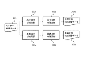
次に、デモザイキング部105でのデモザイキング処理について、図2を参照して説明する。図2は、本実施形態におけるデモザイキング部105の構成例を示す図である。デモザイキング部105は、まず注目画素に対してその周辺の画素を用いて、複数の規定方向のそれぞれの規定方向での補間を行い、その後、方向選択を行うことで、各画素について補間処理結果としてR、G、Bの3原色のカラー画像データを生成する。
Next, the demosaicing process in the
具体的には、デモザイキング部105は、入力された各画素のベイヤー画像データ201に対し、水平方向補間部202により、水平方向の周辺画素を用いて欠落色の画素データを補間することで、水平方向補間の各画素のR、G、B画像データを生成する。ベイヤー画像データ201は、3原色の内の2色の画像データが各画素において欠落している画像データである。また、デモザイキング部105は、各画素のベイヤー画像データ201に対し、垂直方向補間部203により、垂直方向の周辺画素を用いて欠落色の画素データを補間することで、垂直方向補間の各画素のR、G、B画像データを生成する。
Specifically, the
次に、デモザイキング部105は、水平方向補間部202で生成された水平方向補間の各画素のR、G、B画像データについて、水平方向分散度算出部207により画素毎に分散度を算出する。また、デモザイキング部105は、垂直方向補間部203で生成された垂直方向補間の各画素のR、G、B画像データについて、垂直方向分散度算出部208により画素毎に分散度を算出する。そして、デモザイキング部105は、評価値算出部210により、水平方向分散度算出部207及び垂直方向分散度算出部208でそれぞれ算出された水平方向の分散度及び垂直方向の分散度から評価結果としての評価値を算出する。
Next, the
また、偽解像領域の検出や補正を行うために、デモザイキング部105は、Gr・Gb補間部204、彩度検出用補間部205、及び方向を持たない補間部206により、それぞれ各色の画素データを補間する。Gr・Gb補間部204では、Gr画像データ及びGb画像データが生成され、彩度検出用補間部205及び方向を持たない補間部206では、R、G、B画像データが生成される。デモザイキング部105は、偽解像領域判定部209により、Gr・Gb補間部204及び彩度検出用補間部205の各出力画像データに基づいて、偽解像が発生する領域である偽解像領域であるか否かの判定を画素毎に行う。
In addition, in order to detect and correct a false resolution area, the
方向選択・画像生成部211は、評価値算出部210で算出された水平方向の評価値と垂直方向の評価値とを比較し、水平方向補間及び垂直方向補間のうちの評価値の高い方向を選択する。この選択の際に、方向選択・画像生成部211は、偽解像領域判定部209において偽解像領域と判定された画素については、方向を持たない補間部を選択する。そして、方向選択・画像生成部211は、選択した方向に係る補間処理後のR、G、B画像データに基づいて補間画像データを生成し、補間後RGB画像データ212、すなわちデモザイキング・データとして出力する。
The direction selection /
図2に示した水平方向補間部202及び垂直方向補間部203における方向別の補間処理について、図3を参照して説明する。図3は、水平方向補間部202及び垂直方向補間部203の構成例を示す図である。図3に示すように、水平方向補間部202は、水平方向G補間部202a及び水平方向RB補間部202bを有し、垂直方向補間部203は、垂直方向G補間部203a及び垂直方向RB補間部203bを有する。
The direction-specific interpolation processing in the horizontal
水平方向補間部202は、まず水平方向G補間部202aにより、周波数帯域の高いGデータの補間を行い、次に水平方向RB補間部202bにより、Rデータ及びBデータの補間を行い、水平方向補間のR、G、B画像データ202cを生成する。同様に、垂直方向補間部203は、まず垂直方向G補間部203aにより、周波数帯域の高いGデータの補間を行い、次に垂直方向RB補間部203bにより、Rデータ及びBデータの補間を行い、垂直方向補間のR、G、B画像データ203cを生成する。
The horizontal
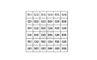
次に、具体的な方向別補間処理の方法を図4に基づいて説明する。Gデータの補間では、注目画素がG色のフィルタに係る画素であれば、当該画素のGデータをそのまま出力する(式1)。また、Gデータの補間では、注目画素がR色のフィルタに係る画素及びB色のフィルタに係る画素であれば、水平方向においては下記の式2を用いて補間データを算出し、垂直方向においては下記の式3を用いて補間データを算出する。なお、式1、式2、式3におけるG33、G34、G43、G44は、図4に便宜的に示した画素符号に対応している(以下の説明においても同様)。例えばG33が画素R33の補間Gデータ、G44が画素B44の補間Gデータを示す。
Next, a specific method of direction-specific interpolation processing will be described with reference to FIG. In the G data interpolation, if the target pixel is a pixel related to a G color filter, the G data of the pixel is output as it is (Formula 1). Further, in the G data interpolation, if the target pixel is a pixel relating to the R color filter and a pixel relating to the B color filter, the interpolation data is calculated using the

Rデータの補間では、注目画素がR色のフィルタに係る画素であれば、当該画素のRデータをそのまま出力する(式4)。また、Rデータの補間では、注目画素がG色のフィルタに係る画素であれば、下記の式5を用いて補間データを算出する。また、Rデータの補間では、注目画素がB色のフィルタに係る画素であれば、下記の式6を用いて補間データを算出する。Rデータの補間では、水平方向と垂直方向とで同じ数式を用いる。なお、Bデータの補間では、Rデータの補間と同様の手法を用いる。具体的には、下記の式4〜式6におけるRをBに置き換えた数式を用いる。
In the interpolation of R data, if the target pixel is a pixel related to the R color filter, the R data of the pixel is output as it is (Formula 4). Further, in the interpolation of R data, if the target pixel is a pixel related to a G color filter, the interpolation data is calculated using Equation 5 below. Further, in the interpolation of R data, if the target pixel is a pixel related to a B color filter, the interpolation data is calculated using
また、前述したように本実施形態におけるデモザイキング部105では、それぞれの規定方向での補間の他に、偽解像の検出や補正を行うための補間を行う。Gr・Gb補間部204は、入力された各画素のベイヤー画像データ201に対し、Gr画素及びGb画素のそれぞれの画素だけを用いて、Gr及びGbの各補間データを算出する。ここで、Gr画素はR画素の横に隣接するG画素を指し、Gb画素はB画素の横に隣接するG画素を指す。Gr・Gb補間部204は、図5に示すようにGr画素、Gb画素に対応するデータからなる画像データに分解する。この際、分解した色フィルタに対応していない画素に対しては、データ値として0を挿入する。その後、Gr・Gb補間部204は、ローパスフィルタ(LPF)による補間処理を行い、すべての画素においてデータを有するGr及びGbの各補間データを算出する。
Further, as described above, the
また、彩度検出用補間部205は、入力された各画素のベイヤー画像データ201に対し、各画素のR、G、B画像データを生成する。彩度検出用補間部205における補間処理について、図6を参照して説明する。図6は、彩度検出用補間部205及び方向を持たない補間部206の構成例を示す図である。図6に示すように、彩度検出用補間部205は、彩度検出用G補間部205a及び彩度検出用RB補間部205bを有する。
Further, the saturation
彩度検出用補間部205は、まず彩度検出用G補間部205aにより、Gデータの補間を行い、次に彩度検出用RB補間部205bにより、Rデータ及びBデータの補間を行い、彩度検出用のR、G、B画像データ205cを生成する。ここで、彩度を算出するための補間が周辺画素の平均を算出する補間方法であると、色ずれや色にじみが起こり、実際とは異なる色になることで、局所領域の彩度判定に誤りを生じさせる可能性がある。そこで、本実施形態では、色ずれや色にじみが起こりにくいように、エッジ部(エッジ成分)を保存するフィルタ係数を使用して彩度を算出することで、偽解像領域判定部209において彩度を検出する際の精度を向上させる。
The saturation
彩度検出用G補間部205aにおけるGデータの補間では、注目画素がG色のフィルタに係る画素であれば、当該画素のGデータをそのまま出力する。また、彩度検出用G補間部205aにおけるGデータの補間では、注目画素がR色のフィルタに係る画素及びB色のフィルタに係る画素であれば、図7に示すような2次微分フィルタの係数を用いて下記の式7のように補間データを算出する。図7において、C画素はR画素又はB画素である。なお、下記の式7における各項は、図4に便宜的に示した画素符号に対応している。
In the interpolation of G data in the saturation detection
なお、エッジ成分を保存するようなフィルタ係数であれば、この限りではない。本実施形態では、2次微分フィルタを用いて補間を行っているが、周辺画素から連続性が強いと判断される方向の補間を適応的に行い、エッジを保存するようにしても良い。例えば、図4に示したR33画素については、下記の式8のように上下及び左右の画素のデータ値の差の絶対値を算出し、連続性が強い方向を判断する。 Note that the present invention is not limited to this as long as it is a filter coefficient that preserves edge components. In this embodiment, interpolation is performed using a second-order differential filter. However, it is also possible to adaptively perform interpolation in the direction in which continuity is determined to be strong from surrounding pixels, and store the edges. For example, for the R33 pixel shown in FIG. 4, the absolute value of the difference between the data values of the upper and lower pixels and the left and right pixels is calculated as shown in Equation 8 below, and the direction of strong continuity is determined.
Hdiff<Vdiffであれば、水平方向の連続性が強いことになり、彩度検出用G補間部205aは、水平方向の画素の画素データで補間を行う。逆であれば、彩度検出用G補間部205aは、垂直方向の画素の画素データで補間を行う。
彩度検出用RB補間部205bは、前述した式4〜式6を用いた場合と同様にしてR及びBの補間データを算出する。
If Hdiff <Vdiff, the continuity in the horizontal direction is strong, and the saturation detection
The saturation detection
また、方向を持たない補間部206は、入力された各画素のベイヤー画像データ201に対し、偽解像判定領域判定部209で偽解像領域と判定された画素領域に適用するための各画素のR、G、B画像データを生成する。方向を持たない補間部206における補間処理について、図6を参照して説明する。図6に示したように、方向を持たない補間部206は、方向を持たないG補間部206a及び方向を持たないRB補間部206bを有する。
In addition, the
方向を持たない補間部206は、まず方向を持たないG補間部206aにより、Gr・Gb補間部204で行う補間と同様の手法で、すべての画素においてデータを有するGr及びGbの各補間データを算出する。さらに、方向を持たない補間部206は、方向を持たないG補間部206aにより、各画素のGr、Gb画像データから、図8に示すようにすべての画素においてGrデータとGbデータの加算平均を行う。これにより、Gr画素とGb画素のデータ値の差を無くすことができる。この補間結果を偽解像判定領域部209で偽解像領域と判定された領域に用いることにより、偽解像を補正できる。
The
方向を持たない補間部206は、次に方向を持たないRB補間部206bにより、Rデータ及びBデータを補間する。方向を持たないRB補間部206bは、前述した式4〜式6を用いた場合と同様にしてR及びBの補間データを算出する。以上のようにして、少なくとも異なる2つの方向の画素を用いて補間データを算出し、方向を持たないR、G、B画像データ206cを生成する。
The
図2に示した偽解像領域判定部209における偽解像領域の判定処理について、図9及び図10を参照して説明する。図9は、偽解像領域判定部209の構成例を示す図である。図10は、偽解像領域しきい値判定処理の例を示すフローチャートである。図9に示すように、偽解像領域判定部209は、GrGb差分算出部(差分検出部)209a、彩度算出部209b、及び偽解像領域しきい値判定部209cを有する。
The false resolution area determination processing in the false resolution
GrGb差分算出部209aは、Gr・Gb補間部204から出力されたGrデータ及びGbデータが入力され、画素毎にGrデータとGbデータとの差分検出を行い、差分の絶対値Gr-bを下記の式9により算出する。また、彩度算出部209bは、彩度検出用補間部205から出力された彩度検出用のR、G、B画像データ205cが入力され、画素毎に下記の式10を用いて彩度Cを算出する。
The GrGb
偽解像領域しきい値判定部209cは、GrGb差分算出部209aから出力された値Gr-b及び彩度算出部209bから出力された彩度Cに基づいて、画素毎に偽解像領域であるか否かの判定を行う。偽解像領域しきい値判定部209cにおける偽解像領域しきい値判定処理を、図10に示すフローチャートに基づいて説明する。
The false resolution area threshold
偽解像領域しきい値判定部209cは、対象画素について、Grデータ及びGbデータの差分絶対値Gr-bと定数のしきい値THaとを比較し、差分絶対値Gr-bがしきい値THaより大きいか否かを判別する(S1001)。その結果、差分絶対値Gr-bがしきい値THaより大きければ、次に、偽解像領域しきい値判定部209cは、彩度Cと定数のしきい値THbとを比較し、彩度Cがしきい値THbより大きいか否かを判別する(S1002)。その結果、彩度Cがしきい値THbより大きければ、偽解像領域しきい値判定部209cは、対象画素が偽解像領域であると判定する(S1003)。偽解像領域しきい値判定部209cは、画像の全画素について、ステップS1001〜S1003の処理を行う。
The false resolution area threshold
前述した偽解像領域しきい値判定処理では、Grデータ及びGbデータの差分絶対値Gr-bと彩度Cのそれぞれを定数のしきい値と比較して判定を行うようにしているが、しきい値を輝度や色相等に応じて非線形に変更することも可能である。さらに、これらの変更をユーザが設定できるようにしても良い。 In the false resolution area threshold value determination process described above, each of the absolute difference value G rb and saturation C of the Gr data and Gb data is compared with a constant threshold value, and the determination is performed. It is also possible to change the threshold value non-linearly according to the luminance, hue, and the like. Further, these changes may be set by the user.
次に、本実施形態における評価値算出処理を、図11に示すフローチャートに基づいて説明する。図11は、評価値算出処理の例を示すフローチャートである。
評価値算出処理において、図2に示した水平方向分散度算出部207は、各画素について欠落色の画素データを補間した水平方向補間のR、G、B画像データ202cを、均等色空間の色信号(値)に変換する(S1101)。本実施形態では、均質性を表す尺度として色差の分散度を算出するために、G、R−G、B−Gの色空間を使用する。ここで、G、R−G、B−Gの色空間ではなく、L*a*b*均等色空間を用いても良いが、L*a*b*値への変換処理は計算量が多いため、L*の代わりにG信号をそのまま用い、a*、b*の代わりにR−G、B−Gを色差信号としている。
Next, the evaluation value calculation process in this embodiment will be described based on the flowchart shown in FIG. FIG. 11 is a flowchart illustrating an example of the evaluation value calculation process.
In the evaluation value calculation processing, the horizontal direction dispersion
次に、水平方向分散度算出部207は、G、R−G、B−Gの各信号に対してそれぞれ分散度σGh 2、σR-Gh 2、σB-Gh 2を算出する(S1102)。ここでは、注目画素を中心とした3×3領域の画素を用いて算出するものとするが、5×5領域の画素や7×7領域の画素を用いて算出しても良く、この限りではない。また、領域内の全画素での分散ではなく、水平方向についてG信号の分散を算出するのであれば、図12(A)に示すように、h11〜h13、h21〜h23、h31〜h33の各々3画素を用いて、G信号の分散σG1 2、σG2 2、σG3 2を算出する。そして、それら分散σG1 2、σG2 2、σG3 2の中で最も大きい分散値σGh 2をG信号の分散値とする。R−G信号、B−G信号の分散についても、図12(B)及び図12(C)に示すようにG信号の分散度算出と同様の処理を行うようにしても良い。
Next, the horizontal direction dispersion
続いて、水平方向分散度算出部207は、下記の式11を用いて水平方向の分散度σh 2を算出する(S1103)。水平方向分散度算出部207は、水平方向補間のR、G、B画像データ202cの全画素について、画素毎に前述したステップS1101〜S1103の処理を行う。
Subsequently, the horizontal direction degree-of-
また、垂直方向分散度算出部208は、垂直方向補間のR、G、B画像データ203cを用いて、ステップS1101〜S1103の処理と同様のステップS1104〜S1106の処理を行い、下記の式12を用いて垂直方向の分散度σv 2を算出する。垂直方向分散度算出部208は、垂直方向補間のR、G、B画像データ203cの全画素について、画素毎にステップS1104〜S1106の処理を行う。
Further, the vertical direction dispersion
次に、評価値算出部210は、前述のようにしてそれぞれ算出された水平方向の分散度σh 2及び垂直方向の分散度σv 2から、下記の式13を用いて水平方向の評価値Ch及び垂直方向の評価値Cvを画素毎に算出する。以上の処理により、画素毎に評価値Ch、Cvが算出され、結果として評価値の2次元プレーンが生成される(S1107)。
Next, the evaluation
ところで、最終的な補間値は評価値によって決定されるため、隣接する画素間で評価値が大きく異なると、トーンジャンプ等の画質劣化の要因となる場合がある。そこで、評価値算出部210は、生成した評価値プレーンに対してローパスフィルタ(LPF)処理を施す(S1108)。LPFのフィルタ係数に関しては、図13(A)に示すようなフィルタ長が3画素の[1,2,1]を用いても、又は図13(B)に示すようなフィルタ長が5画素の[1,4,6,4,1]を用いても良いが、縦横の両方向でフィルタをかけることが望ましい。
By the way, since the final interpolation value is determined by the evaluation value, if the evaluation value differs greatly between adjacent pixels, it may cause image quality degradation such as tone jump. Therefore, the evaluation
方向選択・画像生成部211は、各画素について、評価値算出部210で算出される評価結果としての評価値Ch、Cv及び偽解像領域判定部209での判定結果に基づいて、水平方向補間、垂直方向補間、方向を持たない補間の何れかの画素データを選択する。これにより、方向選択・画像生成部211は、全画素においてそれぞれR、G、Bの色成分の画像データが存在するRGB補間画像データを生成して、補間後RGB画像データ212(デモザイキング・データ)として出力する。
The direction selection /
次に、方向選択・画像生成部211における方向選択・画像生成処理について、図14を参照して説明する。図14は、方向選択・画像生成処理の例を示すフローチャートである。方向選択・画像生成部211は、対象画素について、まず、偽解像領域であると判定されているか否かを判別する(S1401)。その結果、偽解像領域であると判定されていれば、方向選択・画像生成部211は、方向を持たない補間部206での補間処理で生成された方向を持たないR、G、B画像データ206cを選択し、補間後RGB画像データ212として出力する(S1402)。
Next, the direction selection / image generation processing in the direction selection /
一方、偽解像領域であると判定されていなければ、方向選択・画像生成部211は、水平方向の評価値Chと垂直方向の評価値Cvとを比較し、水平方向の評価値Chが垂直方向の評価値Cvより小さいか否かを判別する(S1403)。その結果、水平方向の評価値Chが垂直方向の評価値Cvより小さければ、方向選択・画像生成部211は、水平方向補間のR、G、B画像データ202cを選択し、補間後RGB画像データ212として出力する(S1404)。一方、水平方向の評価値Chが垂直方向の評価値Cvより小さくなければ、方向選択・画像生成部211は、垂直方向補間のR、G、B画像データ203cを選択し、補間後RGB画像データ212として出力する(S1405)。
On the other hand, if it is not determined to be a false resolution area, the direction selection /
第1の実施形態によれば、色ずれや色にじみが起こりにくい、エッジ部を保存する補間処理で生成された彩度検出用のR、G、B画像データから算出した彩度と、Grデータ及びGbデータの差分とに基づいて、画素毎に偽解像が発生する領域であるか判定する。そして、偽解像が発生する領域と判定された画素については、方向を持たない補間部で生成された補間データを画素データとして選択する。これにより、偽解像が発生する領域(画素)の検出を精度良く行い、デモザイキング処理(色補間処理)で発生する偽解像をより適切に補正することができ、画像信号に対するデモザイキング処理を高精度に行うことが可能になる。 According to the first embodiment, saturation and Gr data calculated from R, G, and B image data for saturation detection generated by interpolation processing that preserves an edge portion, in which color misregistration and color bleeding are unlikely to occur. Based on the difference between the Gb data and the Gb data, it is determined whether the area is a region where false resolution occurs for each pixel. Then, for the pixel determined to be a region where false resolution occurs, interpolation data generated by an interpolation unit having no direction is selected as pixel data. As a result, it is possible to accurately detect a region (pixel) in which false resolution occurs, correct more appropriately the false resolution generated in demosaicing processing (color interpolation processing), and perform demosaicing processing on an image signal. Can be performed with high accuracy.
(第2の実施形態)
次に、本発明の第2の実施形態について説明する。
前述した第1の実施形態では、彩度検出用G補間部205の彩度検出用G補間部205aにおけるGデータの補間では、注目画素がR色のフィルタに係る画素及びB色のフィルタに係る画素である場合、図7に示したような2次微分フィルタの係数を用いていた。これに対し、第2の実施形態では、1次微分フィルタの係数を用いてGデータを補間する構成としている。第2の実施形態における撮像装置及びデモザイキング部105の構成は、第1の実施形態において図1、図2を参照して説明したものとほぼ同様であるので、それらの説明は省略する。第2の実施形態では、彩度検出用補間部205の内部構成が第1の実施形態と異なる。
(Second Embodiment)
Next, a second embodiment of the present invention will be described.
In the first embodiment described above, in the interpolation of G data in the saturation detection
図15は、第2の実施形態における彩度検出用補間部205の構成例を示す図である。図15に示すように、彩度検出用補間部205は、彩度検出用GH補間部205d、彩度検出用GV補間部205e、彩度検出用G補間合成部205f、及び彩度検出用RB補間部205bを有する。
FIG. 15 is a diagram illustrating a configuration example of the saturation
第2の実施形態において、彩度検出用GH補間部205dにおけるGデータの補間では、注目画素がG色のフィルタに係る画素であれば、当該画素のGデータをそのまま出力する。彩度検出用GH補間部205dにおけるGデータの補間では、注目画素がR色のフィルタに係る画素及びB色のフィルタに係る画素であれば、図16(A)に示すような水平方向の傾きを考慮した1次微分フィルタの係数を用いて下記の式14のように補間を行う。なお、下記の式14における各項は、図4に便宜的に示した画素符号に対応している。
In the second embodiment, in the G data interpolation in the saturation detection
また、彩度検出用GV補間部205eにおけるGデータの補間では、R色のフィルタに係る画素及びB色のフィルタに係る画素について、図16(B)に示すような垂直方向の傾きを考慮した1次微分フィルタ係数を用いて下記の式15のように補間を行う。
In addition, in the G data interpolation in the saturation detection
なお、図16(A)及び図16(B)において、C画素はR画素又はB画素である。また、フィルタ係数は、図16(A)及び図16(B)に例示したものに限られるものではない。例えばR画素の重みを1以外にしても良い。 In FIGS. 16A and 16B, the C pixel is an R pixel or a B pixel. Further, the filter coefficients are not limited to those illustrated in FIGS. 16 (A) and 16 (B). For example, the R pixel weight may be other than 1.
彩度検出用G補間合成部205fは、彩度検出用GH補間部205dにより得られる補間データと、彩度検出用GV補間部205eにより得られる補間データを基に、補間されたR、B画素位置のGデータにおいて加算平均を行う。彩度検出用RB補間部205bは、第1の実施形態と同様に式4〜式6を用いた場合と同様にしてRデータ及びBデータの補間を行う。以降の実施方法は、第1の実施形態と同じであるため省略する。
The saturation detection G
第2の実施形態によれば、彩度の検出に用いる補間データの生成では、1次微分フィルタを用いて、エッジ成分を保存している。これにより、第1の実施形態と同様に、色にじみや色ずれが起こりにくく、偽解像が発生する領域(画素)の検出を精度良く行うことができ、デモザイキング処理(色補間処理)で発生する偽解像をより適切に補正することができる。 According to the second embodiment, in the generation of interpolation data used for detecting saturation, the edge component is stored using the first-order differential filter. Accordingly, as in the first embodiment, color bleeding and color misregistration hardly occur, and an area (pixel) in which false resolution occurs can be detected with high accuracy, and demosaicing processing (color interpolation processing) can be performed. The generated false resolution can be corrected more appropriately.
(本発明の他の実施形態)
また、本発明は、以下の処理を実行することによっても実現される。即ち、前述した実施形態の機能を実現するソフトウェア(プログラム)を、ネットワーク又は各種記憶媒体を介してシステム或いは装置に供給し、そのシステム或いは装置のコンピュータ(またはCPUやMPU等)がプログラムを読み出して実行する処理である。
(Other embodiments of the present invention)
The present invention can also be realized by executing the following processing. That is, software (program) that realizes the functions of the above-described embodiments is supplied to a system or apparatus via a network or various storage media, and a computer (or CPU, MPU, or the like) of the system or apparatus reads the program. It is a process to be executed.
なお、前記実施形態は、何れも本発明を実施するにあたっての具体化のほんの一例を示したものに過ぎず、これらによって本発明の技術的範囲が限定的に解釈されてはならないものである。すなわち、本発明はその技術思想、又はその主要な特徴から逸脱することなく、様々な形で実施することができる。 The above-described embodiments are merely examples of implementation in carrying out the present invention, and the technical scope of the present invention should not be construed as being limited thereto. That is, the present invention can be implemented in various forms without departing from the technical idea or the main features thereof.
105:デモザイキング部 202:水平方向補間部 203垂直方向補間部 204:Gr・Gb補間部 205:彩度検出用補間部 206:方向を持たない補間部 207:水平方向分散度算出部 208:垂直方向分散度算出部 209:偽解像領域判定部 209a:GrGb差分算出部 209b:彩度算出部 209c:偽解像領域しきい値判定部 210:評価値算出部 211:方向選択・画像生成部
105: Demosaicing unit 202: Horizontal
Claims (12)
前記第1の補間手段により前記補間処理が施された各規定方向の画像データの評価を行う評価手段と、
前記モザイク画像データに対し、各画素において欠落している色の画像データを補間するために、各画素の周辺の画素に係る画像データを用いて方向を持たない補間処理を行う第2の補間手段と、
前記モザイク画像データに対し、各画素において欠落している色の画像データを補間するために、エッジ成分を保存する補間処理を行う第3の補間手段と、
前記第3の補間手段により前記補間処理が施された画像データから彩度を検出する彩度検出手段と、
前記彩度検出手段により検出された彩度に基づいて、画素毎に偽解像が発生する領域であるか否かを判定する判定手段と、
前記判定手段によって偽解像が発生する領域であると判定された画素では、前記第2の補間手段の補間処理によって生成された画像データを選択して補間後の前記複数色の画像データを生成し、前記判定手段によって偽解像が発生する領域ではないと判定された画素では、前記評価手段による評価結果に基づいて、前記第1の補間手段の補間処理によって生成された各規定方向の画像データのいずれかを選択して補間後の前記複数色の画像データを生成する画像生成手段とを有することを特徴とする画像処理装置。 A mosaic image obtained by photoelectrically converting an optical image reflecting a subject image by an image sensor having a plurality of color filters, each pixel having image data corresponding to one of the colors of the plurality of color filters In order to interpolate image data of missing colors in each pixel with respect to a plurality of prescribed directions, data is interpolated using image data relating to pixels in the prescribed direction around each pixel. 1 interpolation means;
Evaluation means for evaluating the image data in each prescribed direction subjected to the interpolation processing by the first interpolation means;
Second interpolation means for performing interpolation processing having no direction using image data relating to pixels around each pixel in order to interpolate image data of a color missing in each pixel with respect to the mosaic image data When,
Third interpolation means for performing interpolation processing for storing edge components in order to interpolate image data of missing colors in each pixel with respect to the mosaic image data ;
Saturation detecting means for detecting saturation from the image data subjected to the interpolation processing by the third interpolation means;
A determination unit that determines whether or not a false resolution occurs for each pixel based on the saturation detected by the saturation detection unit;
In the pixel determined to be a region where false resolution occurs by the determination unit, the image data generated by the interpolation processing of the second interpolation unit is selected to generate the image data of the plurality of colors after interpolation. and, wherein the pixel that spurious resolution is determined not to be a region generated by the determination means, based on the evaluation results by the evaluation means, each defining a direction that is generated by interpolation of the first interpolation means An image processing apparatus comprising: image generation means for selecting any of image data and generating the image data of the plurality of colors after interpolation.
前記モザイク画像データはベイヤー配列の画像データであり、
前記差分検出手段は、赤に対応する画素の水平方向に位置する緑に対応する画素の画像データと、青に対応する画素の水平方向に位置する緑に対応する画素の画像データの差分を検出し、
前記判定手段は、前記差分検出手段により検出された差分、及び、前記彩度検出手段により検出された彩度に基づいて、画素毎に偽解像が発生する領域であるか否かを判定することを特徴とする請求項1又は2記載の画像処理装置。 Furthermore, it has a difference detection means for detecting the difference of the image data,
The mosaic image data is Bayer array image data,
The difference detection means detects a difference between image data of a pixel corresponding to green positioned in the horizontal direction of a pixel corresponding to red and image data of a pixel corresponding to green positioned in the horizontal direction of a pixel corresponding to blue. And
The determination unit determines whether or not a false resolution occurs for each pixel based on the difference detected by the difference detection unit and the saturation detected by the saturation detection unit. The image processing apparatus according to claim 1, wherein the image processing apparatus is an image processing apparatus.
前記第1の補間手段、前記第2の補間手段、及び前記第3の補間手段は、前記補正手段によりホワイトバランス処理が施された前記モザイク画像データに対し、前記補間処理を行うことを特徴とする請求項1〜4の何れか1項に記載の画像処理装置。 Correction means for performing white balance processing on the mosaic image data;
The first interpolation unit , the second interpolation unit , and the third interpolation unit perform the interpolation processing on the mosaic image data that has been subjected to white balance processing by the correction unit. The image processing apparatus according to any one of claims 1 to 4.
前記第1の補間工程で前記補間処理が施された各規定方向の画像データの評価を行う評価工程と、
前記モザイク画像データに対し、各画素において欠落している色の画像データを補間するために、各画素の周辺の画素に係る画像データを用いて方向を持たない補間処理を行う第2の補間工程と、
前記モザイク画像データに対し、各画素において欠落している色の画像データを補間するために、エッジ成分を保存する補間処理を行う第3の補間工程と、
前記第3の補間工程で前記補間処理が施された画像データから彩度を検出する彩度検出工程と、
前記彩度検出工程で検出された彩度に基づいて、画素毎に偽解像が発生する領域であるか否かを判定する判定工程と、
前記判定工程で偽解像が発生する領域であると判定された画素では、前記第2の補間工程での補間処理によって生成された画像データを選択して補間後の前記複数色の画像データを生成し、前記判定工程で偽解像が発生する領域ではないと判定された画素では、前記評価工程での評価結果に基づいて、前記第1の補間工程での補間処理によって生成された各規定方向の画像データのいずれかを選択して補間後の前記複数色の画像データを生成する画像生成工程とを有することを特徴とする画像処理方法。 A mosaic image obtained by photoelectrically converting an optical image reflecting a subject image by an image sensor having a plurality of color filters, each pixel having image data corresponding to one of the colors of the plurality of color filters In order to interpolate image data of missing colors in each pixel with respect to a plurality of prescribed directions, data is interpolated using image data relating to pixels in the prescribed direction around each pixel. 1 interpolation step;
An evaluation step for evaluating image data in each prescribed direction subjected to the interpolation processing in the first interpolation step;
A second interpolation step of performing an interpolation process having no direction using image data relating to pixels around each pixel in order to interpolate image data of a color missing in each pixel with respect to the mosaic image data When,
A third interpolation step for performing interpolation processing for storing edge components in order to interpolate image data of missing colors in each pixel with respect to the mosaic image data ;
A saturation detection step of detecting saturation from the image data subjected to the interpolation processing in the third interpolation step;
A determination step of determining whether or not a false resolution occurs for each pixel based on the saturation detected in the saturation detection step;
In the pixel determined to be a region where false resolution occurs in the determination step, the image data generated by the interpolation process in the second interpolation step is selected, and the image data of the plurality of colors after interpolation is selected. generated, the pixel of spurious resolution is determined not to be a region generated in the determining step, based on the evaluation result in said evaluation step, each generated by interpolation in the first interpolation step And an image generation step of selecting any one of the image data in the prescribed direction and generating the image data of the plurality of colors after interpolation.
前記補間ステップでは、
複数の規定方向について、各画素において欠落している色の画像データを補間するために、各画素の周辺の前記規定方向の画素に係る画像データを用いてそれぞれ補間処理を行う第1の補間ステップと、
前記第1の補間ステップで前記補間処理が施された各規定方向の画像データの評価を行う評価ステップと、
前記モザイク画像データに対し、各画素において欠落している色の画像データを補間するために、各画素の周辺の画素に係る画像データを用いて方向を持たない補間処理を行う第2の補間ステップと、
前記モザイク画像データに対し、各画素において欠落している色の画像データを補間するために、エッジ成分を保存する補間処理を行う第3の補間ステップと、
前記第3の補間ステップで前記補間処理が施された画像データから彩度を検出する彩度検出ステップと、
前記彩度検出ステップで検出された彩度に基づいて、画素毎に偽解像が発生する領域であるか否かを判定する判定ステップと、
前記判定ステップで偽解像が発生する領域であると判定された画素では、前記第2の補間ステップでの補間処理によって生成された画像データを選択して補間後の前記複数色の画像データを生成し、前記判定ステップで偽解像が発生する領域ではないと判定された画素では、前記評価ステップでの評価結果に基づいて、前記第1の補間ステップでの補間処理によって生成された各規定方向の画像データのいずれかを選択して補間後の前記複数色の画像データを生成する画像生成ステップとをコンピュータに実行させるプログラム。 A mosaic image obtained by photoelectrically converting an optical image reflecting a subject image by an image sensor having a plurality of color filters, each pixel having image data corresponding to one of the colors of the plurality of color filters A program for causing a computer to execute an image processing method having an interpolation step for performing interpolation processing on data,
In the interpolation step,
In order to interpolate image data of missing colors in each pixel with respect to a plurality of prescribed directions, a first interpolation step for performing interpolation processing using image data relating to pixels in the prescribed direction around each pixel. When,
An evaluation step for evaluating the image data in each prescribed direction subjected to the interpolation processing in the first interpolation step;
A second interpolation step for interpolating the mosaic image data with no direction by using image data relating to pixels around each pixel in order to interpolate image data of a color missing in each pixel; When,
A third interpolation step for performing interpolation processing for storing edge components in order to interpolate image data of missing colors in each pixel with respect to the mosaic image data ;
A saturation detection step of detecting saturation from the image data subjected to the interpolation processing in the third interpolation step;
A determination step of determining whether or not a false resolution occurs for each pixel based on the saturation detected in the saturation detection step;
In the pixel determined to be a region where false resolution occurs in the determination step, the image data generated by the interpolation process in the second interpolation step is selected, and the image data of the plurality of colors after interpolation is selected. generated, the determination in the pixel spurious resolution is determined not to be a region generated in step, on the basis of the evaluation results at the evaluation step, each generated by interpolation in the first interpolation step A program for causing a computer to execute an image generation step of selecting any of image data in a prescribed direction and generating the image data of the plurality of colors after interpolation.
Priority Applications (4)
| Application Number | Priority Date | Filing Date | Title |
|---|---|---|---|
| JP2014091875A JP6415093B2 (en) | 2014-04-25 | 2014-04-25 | Image processing apparatus, image processing method, and program |
| US14/694,907 US9401006B2 (en) | 2014-04-25 | 2015-04-23 | Image processing apparatus, image processing method, and storage medium |
| KR1020150057668A KR20150123738A (en) | 2014-04-25 | 2015-04-24 | Image processing apparatus and image processing method |
| CN201510203378.6A CN105046631B (en) | 2014-04-25 | 2015-04-27 | Image processing equipment and image processing method |
Applications Claiming Priority (1)
| Application Number | Priority Date | Filing Date | Title |
|---|---|---|---|
| JP2014091875A JP6415093B2 (en) | 2014-04-25 | 2014-04-25 | Image processing apparatus, image processing method, and program |
Publications (3)
| Publication Number | Publication Date |
|---|---|
| JP2015211343A JP2015211343A (en) | 2015-11-24 |
| JP2015211343A5 JP2015211343A5 (en) | 2017-06-08 |
| JP6415093B2 true JP6415093B2 (en) | 2018-10-31 |
Family
ID=54335240
Family Applications (1)
| Application Number | Title | Priority Date | Filing Date |
|---|---|---|---|
| JP2014091875A Active JP6415093B2 (en) | 2014-04-25 | 2014-04-25 | Image processing apparatus, image processing method, and program |
Country Status (4)
| Country | Link |
|---|---|
| US (1) | US9401006B2 (en) |
| JP (1) | JP6415093B2 (en) |
| KR (1) | KR20150123738A (en) |
| CN (1) | CN105046631B (en) |
Families Citing this family (4)
| Publication number | Priority date | Publication date | Assignee | Title |
|---|---|---|---|---|
| JP6415094B2 (en) | 2014-04-25 | 2018-10-31 | キヤノン株式会社 | Image processing apparatus, imaging apparatus, image processing method, and program |
| CN111340714B (en) * | 2019-08-29 | 2023-08-08 | 杭州海康慧影科技有限公司 | Moire pattern processing method and device and electronic equipment |
| WO2021140873A1 (en) * | 2020-01-09 | 2021-07-15 | ソニーグループ株式会社 | Image processing device, image processing method, and imaging device |
| KR20220063575A (en) * | 2020-11-10 | 2022-05-17 | 삼성전자주식회사 | Apparatus and method for obtaining image emplying color separation lens array |
Family Cites Families (12)
| Publication number | Priority date | Publication date | Assignee | Title |
|---|---|---|---|---|
| US5886745A (en) | 1994-12-09 | 1999-03-23 | Matsushita Electric Industrial Co., Ltd. | Progressive scanning conversion apparatus |
| JP3717863B2 (en) | 2002-03-27 | 2005-11-16 | 三洋電機株式会社 | Image interpolation method |
| JP5006067B2 (en) | 2006-06-29 | 2012-08-22 | オリンパス株式会社 | Image processing apparatus, image processing program, and image processing method |
| JP4946581B2 (en) * | 2007-04-05 | 2012-06-06 | ソニー株式会社 | Image processing device |
| JP5574615B2 (en) * | 2009-04-20 | 2014-08-20 | キヤノン株式会社 | Image processing apparatus, control method thereof, and program |
| JP5169994B2 (en) | 2009-05-27 | 2013-03-27 | ソニー株式会社 | Image processing apparatus, imaging apparatus, and image processing method |
| JP5269718B2 (en) * | 2009-08-18 | 2013-08-21 | オリンパス株式会社 | Image processing apparatus, image processing program, and image processing method |
| BR112012008515B1 (en) * | 2009-10-13 | 2021-04-27 | Canon Kabushiki Kaisha | APPARATUS AND IMAGE PROCESSING METHOD, AND RECORDING MEDIA |
| JP2012191465A (en) * | 2011-03-11 | 2012-10-04 | Sony Corp | Image processing apparatus, image processing method, and program |
| JP5899684B2 (en) | 2011-07-11 | 2016-04-06 | ソニー株式会社 | Image processing apparatus, image processing method, and program |
| CN103179407B (en) * | 2013-03-11 | 2015-03-11 | 浙江大学 | Implementation device and implementation method for demosaicing algorithm direction interpolation |
| CN103595980B (en) * | 2013-10-25 | 2015-08-05 | 西安电子科技大学 | Based on the color filter array image demosaicing method of outline non-local mean value |
-
2014
- 2014-04-25 JP JP2014091875A patent/JP6415093B2/en active Active
-
2015
- 2015-04-23 US US14/694,907 patent/US9401006B2/en active Active
- 2015-04-24 KR KR1020150057668A patent/KR20150123738A/en not_active Application Discontinuation
- 2015-04-27 CN CN201510203378.6A patent/CN105046631B/en active Active
Also Published As
| Publication number | Publication date |
|---|---|
| JP2015211343A (en) | 2015-11-24 |
| CN105046631B (en) | 2018-09-11 |
| US9401006B2 (en) | 2016-07-26 |
| KR20150123738A (en) | 2015-11-04 |
| US20150310589A1 (en) | 2015-10-29 |
| CN105046631A (en) | 2015-11-11 |
Similar Documents
| Publication | Publication Date | Title |
|---|---|---|
| JP5574615B2 (en) | Image processing apparatus, control method thereof, and program | |
| JP4700445B2 (en) | Image processing apparatus and image processing program | |
| JP5206796B2 (en) | Image input device | |
| JP5672776B2 (en) | Image processing apparatus, image processing method, and program | |
| WO2013031367A1 (en) | Image processing device, image processing method, and program | |
| JP2004343685A (en) | Weighted gradient based and color corrected interpolation | |
| WO2005112470A1 (en) | Image processing device and image processing program | |
| JP6282123B2 (en) | Image processing apparatus, image processing method, and program | |
| JP6415093B2 (en) | Image processing apparatus, image processing method, and program | |
| JP5917048B2 (en) | Image processing apparatus, image processing method, and program | |
| JP5718138B2 (en) | Image signal processing apparatus and program | |
| JP6415094B2 (en) | Image processing apparatus, imaging apparatus, image processing method, and program | |
| JP2009194721A (en) | Image signal processing device, image signal processing method, and imaging device | |
| JP6143575B2 (en) | Image processing apparatus, image processing method, and image processing program | |
| US8675106B2 (en) | Image processing apparatus and control method for the same | |
| JP4962293B2 (en) | Image processing apparatus, image processing method, and program | |
| US20130038773A1 (en) | Image processing apparatus and control method for the same | |
| JP6552248B2 (en) | IMAGE PROCESSING APPARATUS AND METHOD, IMAGING APPARATUS, AND PROGRAM | |
| JP2014110507A (en) | Image processing device and image processing method | |
| JP6794204B2 (en) | Image processing equipment, image processing methods and programs | |
| JP6862272B2 (en) | Signal processing equipment, signal processing methods and programs | |
| JP4334152B2 (en) | Image interpolation device | |
| JP2018107659A (en) | Luminance signal generating device, luminance signal generating method, and program | |
| KR101315299B1 (en) | Digital image processing apparatus | |
| JP2018107682A (en) | Luminance signal generating device, luminance signal generating method, and program |
Legal Events
| Date | Code | Title | Description |
|---|---|---|---|
| A521 | Request for written amendment filed |
Free format text: JAPANESE INTERMEDIATE CODE: A523 Effective date: 20170421 |
|
| A621 | Written request for application examination |
Free format text: JAPANESE INTERMEDIATE CODE: A621 Effective date: 20170421 |
|
| A977 | Report on retrieval |
Free format text: JAPANESE INTERMEDIATE CODE: A971007 Effective date: 20180412 |
|
| A131 | Notification of reasons for refusal |
Free format text: JAPANESE INTERMEDIATE CODE: A131 Effective date: 20180515 |
|
| A521 | Request for written amendment filed |
Free format text: JAPANESE INTERMEDIATE CODE: A523 Effective date: 20180712 |
|
| TRDD | Decision of grant or rejection written | ||
| A01 | Written decision to grant a patent or to grant a registration (utility model) |
Free format text: JAPANESE INTERMEDIATE CODE: A01 Effective date: 20180904 |
|
| A61 | First payment of annual fees (during grant procedure) |
Free format text: JAPANESE INTERMEDIATE CODE: A61 Effective date: 20181002 |
|
| R151 | Written notification of patent or utility model registration |
Ref document number: 6415093 Country of ref document: JP Free format text: JAPANESE INTERMEDIATE CODE: R151 |