JP6412685B2 - Video projection device - Google Patents
Video projection device Download PDFInfo
- Publication number
- JP6412685B2 JP6412685B2 JP2013239466A JP2013239466A JP6412685B2 JP 6412685 B2 JP6412685 B2 JP 6412685B2 JP 2013239466 A JP2013239466 A JP 2013239466A JP 2013239466 A JP2013239466 A JP 2013239466A JP 6412685 B2 JP6412685 B2 JP 6412685B2
- Authority
- JP
- Japan
- Prior art keywords
- projection
- information
- unit
- user
- image
- Prior art date
- Legal status (The legal status is an assumption and is not a legal conclusion. Google has not performed a legal analysis and makes no representation as to the accuracy of the status listed.)
- Expired - Fee Related
Links
Images


Description
本発明は、実物体に対して映像を重畳し表示する技術に関するものである。 The present invention relates to a technique for superimposing and displaying an image on a real object.
壁に掛けたスクリーンや白色系の壁面に、図形や文字、静止画、映像などのビジュアル的な情報(以下、「ビジュアル情報」と称する。)を投影する投影装置がある。また、この投影装置をインターネット等の公衆ネットワークあるいは社内のLAN等に接続し、遠隔からビジュアル情報を当該投影装置に送信し、コミュニケーションや遠隔会議、遠隔プレゼンテーションに活用することもできる。投影装置の特徴は、比較的容易に大画面表示ができることと、実物に視覚的な情報を直接投影して重畳できることである。 There is a projection device that projects visual information (hereinafter referred to as “visual information”) such as graphics, characters, still images, and images on a wall-mounted screen or white wall. Further, the projection apparatus can be connected to a public network such as the Internet or an in-house LAN, etc., and visual information can be transmitted from the remote to the projection apparatus for communication, remote conference, and remote presentation. The features of the projection device are that it can be displayed on a large screen relatively easily, and that visual information can be directly projected and superimposed on the actual object.
後者の特徴を生かした利用シーンの一つとして、現場の作業者に対して、遠隔からベテランが指導を行うシーンがある。このようなケースでは、現場の作業者は実物を見ながら作業をすることが重要である。そこで、実物体に情報を重畳して提示すれば、作業者は直感的で分かりやすく、作業がやりやすくなると考えられる。 As one of the usage scenes taking advantage of the latter feature, there is a scene where veterans give guidance to workers on site from a distance. In such a case, it is important for the worker on site to work while looking at the actual product. Therefore, if information is superimposed on a real object and presented, it is considered that the operator is intuitive and easy to understand, and the work becomes easier.
ところで、作業の現場によっては、投影面と投影装置の間に障害物が存在することがある。下記特許文献1によると、投影面の状態を撮影するカメラを投影装置に備え、そのカメラで撮影した映像と投影しようした映像との間に相違が生じた場合、前方に障害物(遮蔽物)が存在していると判断することができる装置が提案されている。そのような障害物を検知した場合、投影する映像のレイアウトを変更し、障害物をよけた映像を再構成して提示することも可能である。
By the way, depending on the work site, there may be an obstacle between the projection surface and the projection apparatus. According to the following
ところで、実際の作業現場では、投影面が平面ではなく凸凹した立体面であったり、あるいは、投影面の素材が金属物で投影映像が反射することも考えられる。また、このような作業指示において提示するビジュアル情報は、指示ポインタ等の表示する位置そのものが重要な情報と、図面や図形など表示位置には直接関係しない一般情報が存在する。 By the way, in an actual work site, the projection surface is not a flat surface but a three-dimensional surface that is uneven, or the projection image may be reflected by a metal material of the projection surface. Further, visual information presented in such work instructions includes information in which the display position itself such as an instruction pointer is important, and general information that is not directly related to the display position such as a drawing or a figure.
しかしながら、上記特許文献1では、投影面前方の障害物の検知、および、それによるレイアウト変更を行うことができるが、投影映像を見ている利用者の立ち位置については考慮されておらず、投影面の状態によっては十分に機能しないことがある。このような状態とは、具体的には、投影面における反射による見難さや投影面の凹凸による映像の歪みなどが存在する状態である。
However, in
本発明は以上の課題に鑑みてなされたものであり、実物体にビジュアル情報を投影することができる投影装置において、そのビジュアル情報を見ている利用者の立ち位置に応じて、適した投影位置とすることを目的とする。 The present invention has been made in view of the above problems, and in a projection apparatus capable of projecting visual information onto a real object, a projection position suitable for the standing position of the user who is viewing the visual information. It aims to be.
本発明は、利用者の位置及び投影面を含む被写体までの奥行き情報に基づいて、投影位置が利用者の立ち位置に対して反射の位置関係になる場合や投影面の凹凸度に応じて、その投影位置の変更を行うものである。また、投影するビジュアル情報の内容が、投影位置を変更することについて許可できないビジュアル情報の場合、投影位置を変更せずに、そのままの位置に投影することを可能にするものである。 The present invention is based on the position of the user and the depth information to the subject including the projection plane, depending on the projection positional relationship of the reflection relative to the standing position of the user or the degree of unevenness of the projection plane. The projection position is changed. Further, when the content of visual information to be projected is visual information that cannot be permitted to change the projection position, it is possible to project to the position as it is without changing the projection position.
本発明の一観点によれば、投影面を含む被写体に映像を投影する投影装置において、前記投影装置から被写体までの距離を算出する距離算出部と、前記投影装置を利用する利用者の3次元位置を検出する利用者位置検出部と、前記距離算出部によって算出された被写体までの距離と、前記利用者位置検出部によって検出された利用者の位置とに基づいて、前記投影装置から投影面に向かって映像を正常に投影することが可能であるか否かを判断する正常投影可否判定部と、前記投影装置に投影するオブジェクトの情報を入力するオブジェクト入力部と、前記正常投影可否判定部の判定結果に従って投影する位置を変更して投影する描画部と、を有することを特徴とする投影装置が提供される。 According to an aspect of the present invention, in a projection device that projects an image on a subject including a projection plane, a distance calculation unit that calculates a distance from the projection device to the subject, and a three-dimensional view of a user who uses the projection device Based on the user position detection unit for detecting the position, the distance to the subject calculated by the distance calculation unit, and the position of the user detected by the user position detection unit, the projection device projects the projection plane. A normal projection propriety determination unit that determines whether or not it is possible to normally project an image toward the projector, an object input unit that inputs information of an object to be projected onto the projection device, and the normal projection propriety determination unit And a drawing unit for projecting by changing the projection position according to the determination result.
本発明によれば、実物体にビジュアル情報を投影することができる投影装置において、そのビジュアル情報を見ている利用者の立ち位置に応じて、適した投影位置とすることができる。 According to the present invention, in a projection device capable of projecting visual information onto a real object, a suitable projection position can be set according to the standing position of the user who is viewing the visual information.
本発明によれば、実物体にビジュアル情報を投影することができる投影装置において、そのビジュアル情報を見ている利用者の立ち位置に応じて、適した投影位置とすることができる。 According to the present invention, in a projection device capable of projecting visual information onto a real object, a suitable projection position can be set according to the standing position of the user who is viewing the visual information.
以下、本発明の実施の形態について、図面を参照して詳細に説明する。なお、各図面における表現は理解しやすいように許容できる範囲で誇張して記載しており、実際とは異なる場合がある。
また、以下の説明において、異なる図面においても同じ符号を付した構成は同様の構成であるとして、その説明を省略することとする。
Hereinafter, embodiments of the present invention will be described in detail with reference to the drawings. It should be noted that the expressions in the drawings are exaggerated as far as they are acceptable for easy understanding, and may be different from actual ones.
Moreover, in the following description, the structure which attached | subjected the same code | symbol also in different drawing is suppose that it is the same structure, and suppose that the description is abbreviate | omitted.
(第1の実施の形態)
まず、本発明の第1の実施の形態について、図1〜図9までを参照して説明を行う。
<装置の外観>
図1は、実物体に対して映像を重畳し表示することができる本発明の第1の実施形態における投影装置の外観、及びこの投影装置を用いて実物体に表示を行い、利用者が作業を行っている様子を模式的に示した図である。
(First embodiment)
First, a first embodiment of the present invention will be described with reference to FIGS.
<Appearance of the device>
FIG. 1 shows the appearance of a projection apparatus according to the first embodiment of the present invention that can superimpose and display an image on an actual object, and displays the actual object using this projection apparatus, so that the user can work It is the figure which showed the mode that it is performing typically.
本実施の形態による投影装置107は、プロジェクタ102、マルチカメラ103、及び制御部104(例えば、汎用のパーソナルコンピュータ(PC))を有する。尚、図1では、プロジェクタ102、マルチカメラ103、及び制御部104がそれぞれ独立した構成になっているが、一つの筐体の中にこれらの機能を含んだ構成であっても良い。
プロジェクタ102より投影されたビジュアル情報は、実物体101に投影されている。利用者105は、実物体101に投影された投影情報106を見ながら作業を行っている。ここで、投影情報106は、図面やテキストなどの情報であり、表示位置がそれほど重要ではない情報を代表する例として模式的に示している。
Visual information projected from the
<ブロック構成>
続いて、図2は、本実施形態における投影装置107の一構成例を示す機能ブロック図である。
図2に示すように、投影装置107は、マルチカメラ103、プロジェクタ102、制御部104、及び図1には示していない投影情報入力装置206を有している。ここでは、マルチカメラ103は、さらに、カメラ1(103−1)及びカメラ2(103−2)より構成される。制御部104は、さらに、距離算出部201、利用者立ち位置算出部202、正常投影可否判定部203、描画部204、及びオブジェクト入力部205を有している。
<Block configuration>
Next, FIG. 2 is a functional block diagram showing a configuration example of the
As shown in FIG. 2, the
<処理の内容>
マルチカメラ103は、図1に示す実物体101を含む撮影範囲の映像を取得する装置であり、撮影範囲の被写体を、例えば2台のカメラを用いて異なる位置より撮影することができるようになっている。マルチカメラ103で取得した映像は、制御部104内の距離算出部201に入力される。ここで、マルチカメラ103は、図示したようなマルチカメラに限定されるわけではなく、後述する距離算出部201において算出する視差、あるいは被写体までの距離を直接算出することができる装置であればよく、汎用の測距デバイスに置き換えることが可能である。汎用の測距デバイスとは、具体的には赤外光の投影パターンを用いたアクティブな視差算出デバイスや、被写体までの赤外光の反射時間に基づいて距離を測定するTOF(Time of Flight)による測距デバイスなど、種々のデバイスを適用することができる。視差を算出することができる測距デバイスの場合はマルチカメラ103を単純に置き換えれば良く、直接距離を算出することができる測距デバイスの場合は距離算出部201も含めて置き換えれば良い。
<Content of processing>
The multi-camera 103 is a device that acquires an image of the shooting range including the
制御部104においては、マルチカメラ103で取得した映像を距離算出部201に取り込む。距離算出部201は、カメラ(1)103−1とカメラ(2)103−2で取得した映像をそれぞれ入力とし、それらの映像の間の視差画像を算出する。同時に、カメラ(1)103−1とカメラ(2)103−2の位置関係に基づいて、画像間の視差画像から距離値に変換を行う。距離算出部201は、算出した視差画像と距離値を正常投影可否判定部203と利用者立ち位置算出部202とに出力する。なお、視差画像及び距離値の算出方法については後述する。
In the
制御部104においては、カメラ(2)103−2で取得した映像を利用者立ち位置算出部202に取り込む。利用者立ち位置算出部202は、カメラ(2)103−2で取得した映像と距離算出部201で算出した視差画像と距離値とを入力とし、利用者の立ち位置を算出する。利用者立ち位置算出部202は、算出した利用者の立ち位置を正常投影可否判定部203に出力する。なお、利用者の立ち位置を算出する方法については後述する。
In the
正常投影可否判定部203は、距離算出部201で算出された視差画像および距離値と利用者立ち位置算出部202で算出された利用者立ち位置を入力とし、オブジェクトを正常に投影することが可能であるか否かの判定を行い、その結果を描画部204に出力する。正常投影の可否判定方法については後述する。
The normal projection
オブジェクト入力部205は、制御部104の外部にある図1には示していない投影情報入力装置206より、投影するオブジェクトに関する情報であるオブジェクト情報とリンク情報を入力し、そのまま描画部204に出力する。ここで、投影情報入力装置206は、オブジェクト情報とリンク情報を入力することができる装置であれば良く、例えばキーボードやマウスによる直接入力や、予め作成しておいたオブジェクトの情報を保持できる外部記憶装置などから入力しても良い。オブジェクト情報とリンク情報については後述する。
An
描画部204は、正常投影可否判定部203で算出された判定結果とオブジェクト入力部205からオブジェクト情報とリンク情報を入力とし、必要があればオブジェクトを適切に配置し直して、描画データを外部のプロジェクタ102に出力する。
プロジェクタ102は、描画部204より描画データを受け取ると、それに従って投影を行う。
The
Upon receiving the drawing data from the
<各処理内容の詳細>
距離算出部201で行う、視差画像及び距離値の算出方法について図3を参照して詳細に説明する。
<Details of each processing content>
A method of calculating a parallax image and a distance value performed by the
まず初めに、視差画像の算出方法について説明する。視差とは、異なる位置で撮影した2枚の画像において、被写体の対応する位置が異なり、そのずれのことを示す。視差を画像として表したものが視差画像であり、図4(a)にその例を示す。視差画像は、上述のずれを画素値で表したもので、0〜255になるように正規化されている。値が大きいほど近景(値255、白)を表し、値が小さいほど遠景(値0、黒)を示す。本明細書では、最も近景までの距離と最も遠景までの距離を限定し、視差が255を超えないものとして説明を行う。視差が255を超えて正規化を行う場合は、以下に示す距離値の算出の際に、近景と遠景の視差量を用いて正規化前の視差を再計算を行えば良い。
First, a method for calculating a parallax image will be described. The parallax indicates that the corresponding positions of the subject are different in the two images taken at different positions, and the deviation. A parallax image representing parallax as an image is shown in FIG. 4A. The parallax image represents the above-described shift in terms of pixel values, and is normalized so as to be 0 to 255. A larger value represents a foreground (value 255, white), and a smaller value represents a distant view (
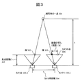
被写体の方向に向いて、カメラ(2)103−2が左側、カメラ(1)103−1が右側に位置しているものとする。図3がその様子を真上から捉えた図である。図3において、点301が被写体の位置する1点を示し、さらに、カメラ(1)103−1、カメラ(2)103−2が示されている。ここで、2台のカメラの内、左側のカメラ(2)103−2を基準(基準カメラ)とし、このカメラの座標系を基準の座標系(以下、「基準座標系」と称する。)とする。また、2台のカメラは特性が同じで、完全に水平に設置されているものとする。なお、2台のカメラの特性が異なる場合や、水平に設置されていない場合の補正方法については、カメラ幾何を用いて対応可能であるが、詳細な説明は省略する。また、カメラ(1)103−1,カメラ(2)103−2の左右の位置関係は逆であっても特に問題はない。視差は、基準カメラで撮影した画像の中から選択した所定サイズの局所ブロックに対応するブロックをもう一方のカメラ画像から抽出(局所ブロックマッチングにより抽出)して、そのずれ量を算出することで求めることができる。
It is assumed that the camera (2) 103-2 is located on the left side and the camera (1) 103-1 is located on the right side in the direction of the subject. FIG. 3 is a diagram showing the situation from directly above. In FIG. 3, a
ここで、カメラ(1)103−1の入力画像をIR(x,y)、カメラ(2)103−2の入力画像をIL(x,y)とし、局所ブロックサイズを15×15とした場合の、視差M(x,y)の算出式は以下の様になる。I(x,y)は、画素(x,y)における輝度値を示している。 Here, the input image of the camera (1) 103-1 is I R (x, y), the input image of the camera (2) 103-2 is I L (x, y), and the local block size is 15 × 15. In this case, the formula for calculating the parallax M (x, y) is as follows. I (x, y) represents the luminance value at the pixel (x, y).

以上、局所領域における輝度値の差の絶対値和(SAD:Sum of Absolute Difference)を最小とするずれ量を、画像内の各画素位置で求めることによって、視差画像を算出することができる。但し、視差画像の算出方法については、上記方法に限定するものではなく、異なる位置に設置したカメラの視差画像を算出できる方法であれば、どのような手法であっても良い。 As described above, the parallax image can be calculated by obtaining the shift amount that minimizes the sum of absolute values (SAD: Sum of Absolute Difference) in the local region at each pixel position in the image. However, the method for calculating the parallax image is not limited to the above method, and any method may be used as long as it can calculate the parallax images of the cameras installed at different positions.
次に、視差画像から距離値を算出する方法について説明する。視差画像から距離値を算出するためには、撮影したカメラの特性を示すカメラパラメータが必要である。カメラパラメータには、内部パラメータと外部パラメータとがあるが、これらは、例えば「コンピュータビジョン−視覚の幾何学−」(コロナ社)の第6章カメラ校正の章に記載された方法を用いて算出することが可能である。
算出したカメラパラメータのうち、焦点距離f(単位m)とカメラ間の距離d(単位m)を用いて以下の様に距離値を算出することができる。
Next, a method for calculating the distance value from the parallax image will be described. In order to calculate the distance value from the parallax image, a camera parameter indicating the characteristics of the photographed camera is necessary. The camera parameters include internal parameters and external parameters, which are calculated by using the method described in Chapter 6 “Camera Calibration” of “Computer Vision-Geometry of Vision” (Corona), for example. Is possible.
Of the calculated camera parameters, the distance value can be calculated as follows using the focal length f (unit m) and the distance d (unit m) between the cameras.
図3において、被写体の一点301は、カメラ(2)103−2の撮影面上の像302、カメラ(1)103−1の撮影面上の像303としてそれぞれ写っている(結像されている)。位置304は、カメラ(2)103−2の像302をカメラ(1)103−1の投影面上に示した点である。従って、像303と位置304との間の画素のずれMが視差となる。また、上記カメラパラメータに関係する焦点距離fを符号305で示し、カメラ間距離dを符号306で示す。
In FIG. 3, one
被写体までの距離z(単位m)と視差Mとの関係は三角測量の原理に従い、一般的に以下のように求めることが可能である。 The relationship between the distance z (unit m) to the subject and the parallax M can be generally obtained as follows according to the principle of triangulation.
ここで、qは画像1画素当たりの長さ(単位m)であり、カメラに採用されている撮像素子によって決まる値である。Mとqの積により、画素のずれ量から実距離の視差に変換することができる。
以上により、異なる位置に配置した2台のカメラで取得した画像を用いて、視差画像及び被写体までの距離値を算出することができる。
Here, q is the length (unit: m) per pixel of the image, and is a value determined by the image sensor employed in the camera. By the product of M and q, the amount of pixel shift can be converted into a real distance parallax.
As described above, the parallax image and the distance value to the subject can be calculated using images acquired by the two cameras arranged at different positions.
続いて、利用者立ち位置算出部202で行われる利用者の立ち位置を算出する方法について、図4を参照しながら詳細に説明する。尚、利用者の立ち位置とは、基準座標における位置(3次元座標)のことである。利用者の立ち位置(以下、「利用者座標」と称する。)を求める方法として、利用者の頭などに超音波や磁気を発生させる機材を装着し、その情報を用いて算出する汎用の3次元位置計測装置を用いても良いが、ここでは距離算出部201で求めた視差画像および距離値を利用する方法について説明する。
Next, a method for calculating the user standing position performed by the user standing
図4(a)は、距離算出部201で算出された視差画像を模式的に示した図である。上述の式(2)によって、視差値は距離値に変換することが可能であることは記載した。このときの距離値は前述の基準座標系におけるz座標である。さらに、基準座標における横方向の位置(x座標)と縦方向の位置(y座標)とが分かれば、利用者の3次元位置を特定することができる。横方向と縦方向の位置については、視差画像において、利用者に対応する画像上の座標と、その視差値から変換した距離値を用いて3次元空間に逆投影することで求めることができる。以下、視差画像における利用者位置に対応する領域を抽出する方法と、その領域の視差値を用いて3次元空間に逆投影して、利用者の横方向の位置(x座標)と縦方向の位置(y座標)を取得する方法について説明する。
FIG. 4A is a diagram schematically illustrating a parallax image calculated by the
初めに、視差画像上の利用者位置に対応する領域及びその座標を求める方法について説明する。具体的には、基準カメラ(2)103−2の映像を使い、利用者の写っていない背景のみの画像と利用者が映っている画像との差分を取ることで、利用者の存在する領域を抽出する。その結果を利用者領域マスクとして取得する(以下、「利用者領域マスク画像」と称する。)。利用者の写っていない背景画像は、例えばシステム起動時に、利用者を除いた状態で撮影をすることで取得可能である。撮影した背景画像は、制御部104内の図示していない保存領域(メモリ)に保持しておけばよい。尚、このような手法は、画像処理の背景差分と呼ばれる一般的な手法である。
First, a method for obtaining an area corresponding to a user position on a parallax image and its coordinates will be described. Specifically, an area where the user exists is obtained by using the video of the reference camera (2) 103-2 and taking the difference between the image of only the background where the user is not shown and the image where the user is shown. To extract. The result is acquired as a user area mask (hereinafter referred to as “user area mask image”). A background image without a user can be obtained, for example, by taking a picture without the user when the system is activated. The captured background image may be held in a storage area (memory) (not shown) in the
ここで、nは利用者マスク画像において、マスク値が1となる画素の総数である。(Xi,Yi)は、i番目のマスク値が1となる画素の座標を示している。ここで、背景差分に使ったカメラと視差画像の基準となるカメラは同じであるため、利用者領域マスク画像と視差画像とは共通の座標軸を持つ。以上により、視差画像における利用者位置に対応する領域(座標)を特定することができる。 Here, n is the total number of pixels whose mask value is 1 in the user mask image. (X i , Y i ) indicates the coordinates of the pixel whose i-th mask value is 1. Here, since the camera used for the background difference and the camera used as the reference for the parallax image are the same, the user area mask image and the parallax image have a common coordinate axis. As described above, the region (coordinates) corresponding to the user position in the parallax image can be specified.
続いて、視差値を用いて3次元空間に逆投影し、利用者の3次元座標を取得する方法について、図4(c)を参照しながら説明する。先ほど算出した重心位置(利用者位置)が図4(c)の座標位置403である。2次元画像上の座標位置403とその視差値を知ることが出来るため、前述の式(2)より利用者までの距離Zを算出することができる。ΔOPAとΔOP’A’は相似の関係になるため、利用者の3次元位置P'(X,Y,Z)を以下の様に算出することができる。
Next, a method of back projecting to a three-dimensional space using a parallax value and acquiring a user's three-dimensional coordinates will be described with reference to FIG. The position of the center of gravity (user position) calculated earlier is the coordinate
以上により、基準座標系における利用者の立ち位置(利用者座標)を算出することができる。ここでは、視差画像内の利用者位置を背景差分によって算出したが、この方法に限定するものではない。例えば、汎用の顔検出処理を用いて画像内から顔領域を検出してやり、上記と同様の処理を行っても良い。 As described above, the user's standing position (user coordinates) in the reference coordinate system can be calculated. Here, the user position in the parallax image is calculated based on the background difference, but the present invention is not limited to this method. For example, a face area may be detected from the image using a general-purpose face detection process, and the same process as described above may be performed.
続いて、正常投影可否判定部203で行う判定処理について、図5〜図7を参照しながら詳細に説明する。
Next, the determination process performed by the normal projection
図5は、図1を真上から捉えた図であり、投影装置107の一部であるプロジェクタ102とマルチカメラ103と、利用者105、及び、投影面101が示されている。ここでは、制御部104の記載は省略している。位置502は、投影装置107によってビジュアル情報を投影する点(以下、「実物体上描画位置」と称する。)を示している。破線501は、その投影点における投影面101の法線を示している。正常投影可否判定部203は、実物体上描画位置502の面の状態によって正常投影が可能であるか否かの判定を行う。具体的には、利用者105がプロジェクタ102から実物体上描画位置502に向かい正反射の方向に位置しているか否かの判定(以下、「反射判定」と称する。)と、実物体上描画位置502周辺の投影面が所定の条件以上に凹凸しているかの判定(以下、「凹凸判定」と称する。)の2種類を行う。正常投影可否判定部203は、この2種類の判定結果に基づいて投影可否の判定を行う。
FIG. 5 is a view of FIG. 1 taken from directly above, and shows a
図6は、図5に記載したような位置関係のときの視差画像(図6(a))と基準カメラの撮影画像(図6(b))を模式的に示した図である。視差画像(図6(a))内の点603(以下、「点T」と称する)と撮影画像(図6(b))内の点602とは同一の位置を示しており、図5における実物体上描画位置502に対応している。また、同図(b)内の601、605、606はそれぞれ図1における101、105、106に対応している。
FIG. 6 is a diagram schematically showing a parallax image (FIG. 6A) and a captured image of the reference camera (FIG. 6B) in the positional relationship as described in FIG. 5. A point 603 (hereinafter referred to as “point T”) in the parallax image (FIG. 6A) and a
ここで、Trefは反射判定のパラメータで、正の定数である。例えば、15度に設定する。続いて、凹凸判定について説明する。凹凸判定は、実物体上描画位置502に対応する603を含む、所定範囲内の近傍の視差値(距離値でも良いが記載しない)を用いて行う。その凹凸判定の判定式は以下の通りである。
Here, T ref is a parameter for reflection determination, and is a positive constant. For example, it is set to 15 degrees. Subsequently, the unevenness determination will be described. The unevenness determination is performed using a parallax value in the vicinity including a
ここで、Tbumpは凹凸判定のパラメータで、正の整数である。設定については、1画素の視差がどれくらいの距離に対応するかによって決めることができる。例えば、距離が10cm程度の視差量を設定すればよい。
以上、反射判定結果JudgeFref(T)と凹凸判定結果JudgeFbump(T)が求められると、正常投影可否判定部203は、以下のように判定を行う。
Here, T bump is a parameter for determining unevenness and is a positive integer. The setting can be determined according to how far the parallax of one pixel corresponds. For example, a parallax amount with a distance of about 10 cm may be set.
As described above, when the reflection determination result JudgeF ref (T) and the unevenness determination result JudgeF bump (T) are obtained, the normal projection
![]()
![]()
正常投影可否判定部203は、以上により判定結果を生成し結果を出力する。上記式(10)では、反射判定と凹凸判定の両方を用いて最終判定を行ったが、いずれか一方のみを用いて最終判定を行っても良い。
The normal projection
次いで、描画部204で行う投影位置の制御方法について詳細に説明する。描画部204では、正常投影可否判定203において「正常投影不可」の判定がされた場合(JudgeF(T)が1あるいはTRUEの場合)に、投影位置の制御を行う。正常投影可否判定部203において「正常投影可」の判定がされた場合(JudgeF(T)が0あるいはFALSEの場合)は、通常の投影位置にそのまま投影を行う。以下は、「正常投影不可」の場合について説明を行う。
Next, a method for controlling the projection position performed by the
描画部204は、オブジェクト入力部205よりオブジェクト情報とリンク情報を受け取る。ここで、オブジェクト情報とリンク情報について図8を参照しながら説明する。オブジェクト情報800は、オブジェクトID801、オブジェクト種類802a、オブジェクト引数長802b、オブジェクト引数803c、オブジェクト位置804、及びリンクID805より構成される情報であり、オブジェクトの描画内容を示す情報になっている。一方、リンク情報810は、リンクID811、リンク長812a、リンク−オブジェクトID(s)813b、及び移動シフト量814より構成される情報であり、オブジェクト間のリンク情報を示している。以下、個々の項目について説明をする。
The
初めに、オブジェクト情報800の項目について説明する。オブジェクトID801は、描画オブジェクト毎に設定される固有のIDである。オブジェクト種類802aは、オブジェクトの種類を示す情報で、例えば、直線、曲線、点、文字、矩形、画像、動画等のビジュアル情報の種類を示す項目である。オブジェクト引数長802bは、オブジェクトの種類によって変わる引数の長さを指定する項目であり、803cの格納サイズを決める。オブジェクト引数803cは、オブジェクト種類802aに固有の引数を格納する項目である。例えば、オブジェクトの色や線の太さ、始点や終点、曲率、キャラクタコード、ストリングコード、画像サイズ、画像・動画データ保存先等、オブジェクトを描画する際に必要な引数である。オブジェクト位置804は、オブジェクトの描画位置を示す情報である。リンクID805は、関連するオブジェクトのリンク情報を格納する項目で、リンク情報810のリンクIDを格納している。お互いにリンクしたオブジェクトは、レイアウトを変更する際に共通の変更(描画位置の変更)を行うものとする。リンク情報は必須の情報ではないが、後述のレイアウト変更を行う際に、関連するオブジェクトのレイアウト崩れを抑制することができる。続いて、リンク情報810の項目について説明する。リンクID811は、リンク情報毎に与えられる固有のIDである。リンク長812aは、関連するオブジェクトのIDを格納する813bの格納サイズを決める項目である。リンク−オブジェクトID(s)813bは、関連するオブジェクト(レイアウト変更時に同じ移動をさせるオブジェクト群)のIDを格納する項目である(複数も可能である)。移動シフト量814は、リンクしているオブジェクト全体の移動量を格納する項目である。リンク情報810の移動シフト量814は、入力時には0が設定されている。後述のレイアウト変更時に移動量が設定され、リンクされたオブジェクト全てを同じ移動量分シフトして描画する。これにより、リンクされたオブジェクト間のレイアウトを崩すことなく描画することができる。オブジェクトのレイアウトの変更に関しては、所定の条件でオブジェクトを移動させ、その移動先で前述の投影可否判定を繰り返し行い問題がなければそこに移動させれば良い。所定の条件とは、元々の投影位置から移動量をできるだけ少なくなるように制御することである。具体的な方法としては、元々の描画位置から新規移動先までの距離が極力少なくなるように制御すればよい。また、従来特許文献1に記載のレイアウト変更部で行うレイアウトの変更方法を用いても良い。このときの評価値は、複数の移動先について、前述の正常投影可否判定部203の判定結果を用いれば良い。また、特許文献1に記載の移動先に関して、ユーザの指示を入力し、その結果によって移動先を決めるような仕組みを用いても良い。
First, the items of the object information 800 will be described. The object ID 801 is a unique ID set for each drawing object. The
<フローチャート>
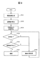
次いで、制御部104の処理の流れについて、図9及び図2を用いて説明する。
(ステップS101)
制御部104は、外部に接続されたマルチカメラ103で撮影された映像を取り込み、距離算出部201に入力する。距離算出部201は、映像を入力し、前述の方法により視差画像を算出する。その後、ステップS102に進む。
<Flowchart>
Next, the processing flow of the
(Step S101)
The
(ステップS102)
距離算出部201は、算出した視差画像とカメラパラメータに基づいて距離値を算出し、結果を利用者立ち位置算出部202と正常投影可否判定部203に出力する。その後、ステップS103に進む。
(Step S102)
The
(ステップS103)
利用者立ち位置算出部202は、距離算出部201より視差画像及び距離値を入力し、前述の方法により利用者の立ち位置を算出する。利用者立ち位置算出部202は、算出した結果を、正常投影可否判定部203に出力する。その後、ステップS104に進む。
(Step S103)
The user standing
(ステップS104)
正常投影可否判定部203は、利用者立ち位置算出部202より利用者の立ち位置を入力し、さらに、距離算出部201より視差画像及び距離値を入力し、前述の反射判定を行う(オブジェクト位置804に移動シフト量814を加えた位置で判定する)。正常投影可否判定部203は、反射判定によって正常投影が可能と判断した場合、処理をステップS105に進める。正常投影可否判定部203は、反射判定によって正常投影が不可と判断した場合、ステップS106に処理を進める。
(Step S104)
The normal projection
(ステップS105)
正常投影可否判定部203は、続いて、前述の凹凸判定を行う。正常投影可否判定部203は、凹凸判定によって正常投影が可能と判断した場合、処理をステップS107に進める。正常投影可否判定部203は、凹凸判定によって正常投影が不可と判断した場合、ステップS106に処理を進める。
(Step S105)
Subsequently, the normal projection
(ステップS106)
描画部204は、正常投影可否判定部203において正常投影が不可と判断された場合、前述の投影位置の変更を行い、ステップS104に戻り前述の処理を繰り返す。
(Step S106)
When the normal projection
(ステップS107)
描画部204は、正常投影可否判定部106において正常投影が可能と判断された場合、描画を行う。
(Step S107)
The
以上の処理により、ビジュアル情報を見ている利用者の立ち位置に応じて、投影内容が見難いことが予想される場合に、その投影位置を変更して描画することが可能になる。 With the above processing, when it is predicted that the projection content is difficult to see according to the standing position of the user who is viewing the visual information, the projection position can be changed and the drawing can be performed.
(第2の実施の形態)
次に、本発明の第2の実施の形態について、図10から図12までを参照しながら説明を行う。
(Second Embodiment)
Next, a second embodiment of the present invention will be described with reference to FIGS.
<装置の外観例>
図10は、実物体に対して映像を重畳して表示することができる本発明の第2の実施形態による投影装置の外観及び当該装置を用いて実物体に表示を行い、利用者が作業を行っている状態を模式的に示した図である。本実施の形態が第1の実施の形態と異なる点は、実物体101に投影しているビジュアル情報に、投影位置が重要なポインタ(1001)情報があることである。利用者105は、実物体101に投影された情報(投影情報106とポインタ情報1001)を見ながら作業を行っている。以上、図10は本発明の投影装置を利用しているシーンの一例を示す図である。
<Appearance example of the device>
FIG. 10 shows an appearance of a projection apparatus according to the second embodiment of the present invention that can display an image superimposed on an actual object, and displays the actual object using the apparatus, so that the user can perform work. It is the figure which showed the state currently performed typically. This embodiment is different from the first embodiment in that the visual information projected on the
<ブロック構成例>
本実施の形態における投影装置の機能ブロック図及び処理内容については第1の実施形態と同じである(図2参照)。第1の実施の形態と異なる点は、第1の実施の形態のオブジェクト情報800(図8)に「オブジェクト移動可否」項目を追加した点である。本実施の形態で使用するオブジェクト情報について図11を参照しながら説明する。
<Block configuration example>
The functional block diagram and processing contents of the projection apparatus in the present embodiment are the same as those in the first embodiment (see FIG. 2). The difference from the first embodiment is that an “object movement availability” item is added to the object information 800 (FIG. 8) of the first embodiment. Object information used in the present embodiment will be described with reference to FIG.
オブジェクト情報1100は、オブジェクトID1101、オブジェクト種類1102a、オブジェクト引数長1102b、オブジェクト引数1103c、オブジェクト位置1104、オブジェクト移動可否1105、及びリンクID1106より構成される情報で、オブジェクトの描画内容を示す情報になっている。一方、リンク情報は、第1の実施の形態と同じである。
以下において、オブジェクト情報1100の各項目について説明する。
The object information 1100 is information including an
Hereinafter, each item of the object information 1100 will be described.
オブジェクトID1101は、描画オブジェクト毎に設定される固有のIDである。
オブジェクト種類1102aは、オブジェクトの種類を示す情報で、例えば、直線、曲線、点、文字、矩形、画像、動画等のビジュアル情報の種類を示す項目である。オブジェクト引数長1102bは、オブジェクトの種類によって変わる引数の長さを指定する項目で、1103cの格納サイズを決める。オブジェクト引数1103cは、オブジェクト種類1102aに固有の引数を格納する項目である。例えば、オブジェクトの色や線の太さ、始点や終点、曲率、キャラクタコード、ストリングコード、画像サイズ、画像・動画データ保存先等、オブジェクトを描画する際に必要な引数である。オブジェクト位置1104は、オブジェクトの描画位置を示す情報である。
The
The
オブジェクト移動可否1105は、本実施の形態で追加した項目で、レイアウトの変更を許可するか否かを制御するフラグである。このフラグが設定(「移動不可」)されている場合は、正常投影可否判定部203において正常投影不可と判断されても投影位置の変更は行わない。詳細は後述する。リンクID1106は、関連するオブジェクトのリンク情報を格納する項目で、リンク情報のリンクIDを格納している。お互いにリンクしたオブジェクトは、レイアウトを変更する際に共通の変更(描画位置の変更)を行うものとする。リンク情報は必須の情報ではないが、後述のレイアウト変更を行う際に、関連するオブジェクトのレイアウト崩れを抑制することができる。
The object movement permission /
<フローチャート>
制御部104の処理の流れについて、図12及び図2を参照しながら説明する。
(ステップS201)
制御部104は、外部に接続されたマルチカメラ103で撮影された映像を取り込み、距離算出部201に入力する。距離算出部201は、映像を入力し、前述の方法により視差画像を算出する。その後、ステップS202に進む。
<Flowchart>
The processing flow of the
(Step S201)
The
(ステップS202)
距離算出部201は、算出した視差画像とカメラパラメータに基づいて距離値を算出し、結果を利用者立ち位置算出部202と正常投影可否判定部203に出力する。その後、ステップS203に進む。
(Step S202)
The
(ステップS203)
利用者立ち位置算出部202は、距離算出部201より視差画像及び距離値を入力し、前述の方法により利用者の立ち位置を算出する。利用者立ち位置算出部202は、算出した結果を、正常投影可否判定部203に出力する。その後、ステップS204に進む。
(Step S203)
The user standing
(ステップS204)
正常投影可否判定部203は、オブジェクト入力部205より入力したオブジェクト情報とリンク情報のうち、オブジェクト情報に格納されたオブジェクト移動可否項目1105に従って、正常投影可否判定を行うか否かの判断を行う。正常投影可否判定部203は、オブジェクト移動可否項目1105の値が「移動不可」の場合、描画位置の変更が行えないため、処理をステップS208に進める。正常投影可否判定部203は、オブジェクト移動可否項目1105の値が「移動可能」な場合、処理をステップS205に進める。
(Step S204)
The normal projection
(ステップS205)
正常投影可否判定部203は、利用者立ち位置算出部202より利用者の立ち位置を入力し、さらに、距離算出部201より視差画像及び距離値を入力し、前述の反射判定を行う(オブジェクト位置1104に移動シフト量814を加えた位置で判定する)。正常投影可否判定部203は、反射判定によって正常投影が可能と判断した場合、処理をステップS206に進める。正常投影可否判定部203は、反射判定によって正常投影が不可と判断した場合、ステップS207に処理を進める。
(Step S205)
The normal projection
(ステップS206)
正常投影可否判定部203は、続いて、前述の凹凸判定を行う(オブジェクト位置1104に移動シフト量814を加えた位置で判定する)。正常投影可否判定部203は、凹凸判定によって正常投影が可能と判断した場合、処理をステップS208に進める。正常投影可否判定部203は、凹凸判定によって正常投影が不可と判断した場合、ステップS207に処理を進める。
(Step S206)
Subsequently, the normal projection
(ステップS207)
描画部204は、正常投影可否判定部203において正常投影が不可と判断された場合、前述の投影位置の変更を行い(移動シフト量814に移動量を設定)、ステップS205に戻り処理を繰り返す。
(Step S207)
When the normal projection
(ステップS208)
描画部204は、正常投影可否判定部203において正常投影が可能と判断された場合、その描画を行う。
(Step S208)
When the normal projection
以上により、ビジュアル情報を見ている利用者の立ち位置に応じて、投影内容が見難いことが予想される場合にその投影位置を変更することが可能になる。同時に、投影位置を変えることに問題のあるビジュアル情報の場合は、そのままの位置に表示を行うように制御することができる。 As described above, according to the standing position of the user who is viewing the visual information, the projection position can be changed when it is predicted that the projection content is difficult to see. At the same time, in the case of visual information that has a problem in changing the projection position, it can be controlled to display it as it is.
(第3の実施の形態)
次に、本発明の第3の実施の形態について、図13から図17までを参照しながら説明を行う。
(Third embodiment)
Next, a third embodiment of the present invention will be described with reference to FIGS.
<装置の外観例>
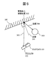
図13は、実物体に対して映像を重畳し表示することができる本発明の第3の実施の形態による投影装置および遠隔地から投影内容をコントロールする端末の外観例、及び、当該投影装置を用いて実物体に表示を行い、利用者が作業を行っている様子を模式的に示した図である。
<Appearance example of the device>
FIG. 13 shows an example of the appearance of a projection apparatus according to a third embodiment of the present invention that can superimpose and display an image on a real object, and a terminal that controls projection contents from a remote location, and the projection apparatus. It is the figure which showed typically a mode that it displayed on a real object using and the user is working.
これまでの実施の形態と異なる点は、遠隔地から投影内容をコントロールすることができる端末1301(以下、「遠隔端末」と称する。)が存在するところである。
遠隔端末1301は、Wi−Fi(Wireless Fidelity)等の無線通信を行う機能及び装置を備えており、遠隔地から投影装置107にビジュアル情報を送信することができる。遠隔端末1301の表示面1302は、タッチパネル方式(静電容量方式、加圧方式等どのような方式でも良い)のディスプレイになっており、画面をタッチしてビジュアル情報を操作したり、指示位置を示すポインタを操作したりすることができる。表示面1302には、投影装置107のある作業現場の映像が映し出されている。実物体101が1305として、利用者105が1306として、ポインタ1001が1303として、投影情報106が1304として表示されている。遠隔端末1301を用いてベテランが作業現場に遠隔から指示を出しているシーンを示している図である。
A difference from the embodiments described above is that there is a terminal 1301 (hereinafter referred to as a “remote terminal”) that can control projection contents from a remote location.
The remote terminal 1301 has a function and apparatus for performing wireless communication such as Wi-Fi (Wireless Fidelity), and can transmit visual information to the
<ブロック構成例>
本実施の形態の機能ブロック図について、図14と図15とを参照しながら説明する。図14が投影装置107に関するブロック図で、図15が遠隔端末1301に関するブロック図になっている。
<Block configuration example>
A functional block diagram of the present embodiment will be described with reference to FIG. 14 and FIG. FIG. 14 is a block diagram relating to the
初めに、投影装置107について説明する。制御部1401に接続されたマルチカメラ103とプロジェクタ102は第1の実施の形態と同様である。制御部1401の内部の点線で示した部分1402は第1の実施の形態と同様であるためその説明を省く。制御部1401に追加されたブロックは、符号化部1403、送信部1404、復号部1405、及び受信部1406である。送信部1404と受信部1406は、外部のネットワーク(インターネットや社内LAN等)に接続(接続方法は無線・有線どちらの方式でも良い)しており、後述する遠隔端末1301との間でデータの送受信を行うことができる。
First, the
続いて、遠隔端末1301について説明する。図15に示すように、遠隔端末1301は、遠隔端末制御部1501と遠隔端末入出力部1502とを有している。遠隔端末制御部1501は、受信部1503、復号部1504、制御部1505、符号化部1506、及び送信部1507を有している。遠隔端末入出力部1502は、ディスプレイ1507と入力部1508とを有している。遠隔端末入出力部1502内のディスプレイ1507と入力部1508とは一体形成されていても良く、所謂タッチパネルディスプレイとなっていても良い。
Next, the remote terminal 1301 will be described. As shown in FIG. 15, the remote terminal 1301 has a remote terminal control unit 1501 and a remote terminal input / output unit 1502. The remote terminal control unit 1501 includes a
<処理の内容>
続いて、各ブロックにおける処理の内容に関して、第1の実施の形態と異なる部分についてのみ説明する。初めに投影装置107について説明を行い、続いて遠隔端末1301について説明する。
<Content of processing>
Subsequently, regarding the contents of processing in each block, only the parts different from the first embodiment will be described. First, the
投影装置107の制御部1401は、マルチカメラ(2)103−2で撮影した映像を符号化部1403に取り込む。符号化部1403は、入力した映像をよりデータ量の少ない符号に圧縮(例えば、国際標準動画圧縮規格H.264等)し、その符号化データを送信部1404に出力する。送信部1404は、符号化部1403から符号化されたデータを入力し、ネットワークを通じて外部(例えば、遠隔端末1301)に通信規格(TCP/IP、UDP、SIP等)に合わせて符号化された符号化データを送信する。制御部1401は、外部(例えば、遠隔端末1301)より送られてきたデータを受信部1406に取り込む。このとき受信するデータは、オブジェクト情報とリンク情報とを符号化したデータである。受信部1406は、送られてきた符号化データを取り込むと、そのデータを復号部1405に出力する。復号部1405は、受信部1406より符号化データを入力し、オブジェクト情報とリンク情報に復号(後述の遠隔端末1301の符号化部1506で行った圧縮処理とは逆の処理)を行い、結果をオブジェクト入力部205に出力する。制御部1401は、1402において、マルチカメラ映像とオブジェクト情報とを入力し、前述の方法(第1の実施の形態あるいは第2の実施の形態)に従って投影映像を生成する。プロジェクタ102は、生成された投影映像を投影する。
The control unit 1401 of the
続いて、遠隔端末1301について説明する。外部のネットワークより送られてきたデータは、遠隔端末制御部1501の内部にある受信部1503に取り込まれ、データの中から前述の符号化部1403で生成された符号化データにあたるデータを取り出し、取り出した符号化データを復号部1504に出力する。復号部1504は、受信部1503より符号化データを入力し、前述の符号化部1403で行った圧縮処理とは逆の処理を行い、映像データを復号する。復号部1504は、復号された映像データを遠隔端末入出力部1502の内部にあるディスプレイ1507に出力する。ディスプレイ1507は、復号部1504より入力した映像を表示する。入力部1508は、外部からのタッチ入力操作を受け付け、その座標情報を制御部1505に出力する。制御部1505は、入力部1508でタッチ入力した情報を受け取るとともに、図示していないオブジェクト情報を入力する装置(例えば、前述のキーボードやマウス、あるいは外部記憶装置)より、オブジェクト情報とリンク情報を受け取る。制御部1505は、入力部1508より入力した情報より、オブジェクト情報の内容(例えば、オブジェクトの種類、位置情報、オブジェクトの引数等)を変更し、結果を符号化部1506に出力する。符号化部1506は、オブジェクト情報とリンク情報とを受け取り、よりデータ量の少ない符号に圧縮(例えば、ZIP圧縮)を行う。符号化部1506は、圧縮した符号化データを送信部1507に出力する。送信部1507は、符号化部1506より符号化データを受け取り、ネットワークを介して外部(例えば、投影装置の制御部1401)に通信規格(TCP/IP、SIP等)に乗せて送信する。
Next, the remote terminal 1301 will be described. The data sent from the external network is taken into the
<フローチャート>
第3の実施の形態について、投影装置107と遠隔端末1301の処理フローについて図16と図17とを参照しながら説明する。初めに投影装置107の処理フローについて図16を用いて説明する。
<Flowchart>
In the third embodiment, a processing flow of the
(ステップS301)
投影装置107は、描画処理、受信処理、送信処理を平行して開始させ、ステップS302、ステップS304、ステップS306に進める。
(Step S301)
The
(ステップS302)
投影装置107は、前述の第1の実施の形態におけるフローチャートのステップS101からステップS107の処理、あるいは、第2の実施の形態におけるフローチャートのステップS201からステップS208に該当する処理を実施する。その後、ステップS303に進む。
(Step S302)
The
(ステップS303)
投影装置107は、図示していない装置全体をコントロールする全体制御部によって、描画処理を終了するか否かの判断をする。全体制御部は、描画処理を終了する場合、他の受信処理と送信処理も合わせて終了させる。全体制御部は、描画処理を終了させない場合、ステップS302戻り処理を繰り返す。
(Step S303)
The
(ステップS304)
投影装置107は、投影装置107の内部にある受信部1406で、外部から送られてくるデータを受信する。受信部1406は、データを受信すると、オブジェクト情報とリンク情報を符号化したデータを取り出し、復号部1405に出力する。復号部1405は、受信部1406より符号化データを受け取ると、データの復号を行い、オブジェクト情報とリンク情報を分離する。復号部1405は、オブジェクト情報とリンク情報をオブジェクト入力部205に出力する。その後、ステップS305に進む。
(Step S304)
The
(ステップS305)
投影装置107は、図示していない装置全体をコントロールする全体制御部によって、受信処理を終了するか否かの判断をする。全体制御部は、受信処理を終了する場合、他の描画処理と送信処理も合わせて終了させる。全体制御部は、受信処理を終了させない場合、ステップS304戻り処理を繰り返す。
(Step S305)
The
(ステップS306)
投影装置107は、カメラ(2)103−2の映像を取り込み、符号化部1403に入力させる。符号化部1403は、入力したカメラ映像を圧縮し符号化する。符号化部1403は、符号化されたデータを送信部1404に出力する。送信部1404は、符号化部1403より符号化データを入力し、通信可能なデータに加工した後、投影装置107の外部に送信する。その後、ステップS307に進む。
(Step S306)
The
(ステップS307)
投影装置107は、図示していない装置全体をコントロールする全体制御部によって、送信処理を終了するか否かの判断をする。全体制御部は、送信処理を終了する場合、他の描画処理と受信処理も合わせて終了させる。全体制御部は、送信処理を終了しない場合、ステップS306戻り処理を繰り返す。
(Step S307)
The
続いて、遠隔端末1301の処理フローについて図17を参照して説明する。
(ステップS401)
遠隔端末1301は、受信・描画処理、タッチ入力・送信処理を平行して開始させ、ステップS402、ステップS405に進める。
(ステップS402)
遠隔端末1301は、内部にある受信部1503で、外部から送られてくるデータを受信する。受信部1503は、データを受信すると、映像符号化データを取り出し、復号部1504に出力する。復号部1504は、受信部1503より映像符号化データを受け取ると、データの復号を行い、結果をディスプレイ1507に出力する。その後、ステップS403に進む。
Next, the processing flow of the remote terminal 1301 will be described with reference to FIG.
(Step S401)
The remote terminal 1301 starts reception / drawing processing and touch input / transmission processing in parallel, and proceeds to step S402 and step S405.
(Step S402)
The remote terminal 1301 receives data sent from the outside by an
(ステップS403)
ディスプレイ1507は、復号部1504より映像データを受け取ると、その映像をディスプレイに表示する。その後、ステップS404に進む。
(Step S403)
Upon receiving the video data from the
(ステップS404)
遠隔端末1301は、図示していない端末全体をコントロールする全体制御部によって、受信・描画処理を終了するか否かの判断をする。全体制御部は、受信・描画処理を終了する場合、他のタッチ入力・送信処理も合わせて終了させる。全体制御部は、受信・描画処理を終了しない場合、ステップS402に戻り処理を繰り返す。
(Step S404)
The remote terminal 1301 determines whether or not to end the reception / drawing process by an overall control unit that controls the entire terminal (not shown). When terminating the reception / drawing process, the overall control unit also terminates other touch input / transmission processes. If the reception / drawing process is not terminated, the overall control unit returns to step S402 and repeats the process.
(ステップS405)
遠隔端末1301の入力部1508は、外部からのタッチ入力を受け付け、その情報を制御部1505に出力する。制御部1505は、オブジェクト情報の内容(例えば、オブジェクトの種類、位置情報、オブジェクトの引数等)を変更し、結果を符号化部1506に出力する。その後、ステップS406に進む。
(Step S405)
The
(ステップS406)
符号化部1506は、制御部1505よりオブジェクト情報とリンク情報を受け取り、よりデータ量の少ない符号に圧縮を行う。符号化部1506は、圧縮した符号化データを送信部1507に出力する。送信部1507は、符号化部1506より符号化データを受け取り、ネットワークを介して外部(例えば、投影装置の制御部1401)に通信規格に乗せて送信する。その後、ステップS407に進む。
(Step S406)
The
(ステップS407)
遠隔端末1301は、図示していない端末全体をコントロールする全体制御部によって、タッチ入力・送信処理を終了するか否かの判断をする。全体制御部は、タッチ入力・送信処理を終了する場合、他の受信・描画処理も合わせて終了させる。全体制御部は、タッチ入力・送信処理を終了しない場合、ステップS405戻り処理を繰り返す。
(Step S407)
The remote terminal 1301 determines whether or not to end the touch input / transmission process by an overall control unit that controls the entire terminal (not shown). When terminating the touch input / transmission process, the overall control unit also terminates other reception / drawing processes. If the touch input / transmission process is not terminated, the overall control unit repeats the return process in step S405.
本実施の形態によれば、実物体にビジュアル情報を投影することができる投影装置において、そのビジュアル情報を見ている利用者の立ち位置に応じて、投影内容が見難いことが予想される場合にその投影位置を変更することが可能になる。
また、投影位置を変えることに問題のあるビジュアル情報の場合は、そのままの位置に表示を行うように制御をすることができる。
According to the present embodiment, in a projection device that can project visual information onto a real object, it is expected that the projection content is difficult to see depending on the standing position of the user who is viewing the visual information. It is possible to change the projection position.
Further, in the case of visual information having a problem in changing the projection position, control can be performed so that the display is performed at the position as it is.
<第1から第3までの実施の形態について>
上記各実施の形態において、添付図面に図示されている構成等については、あくまで一例であり、これらに限定されるものではなく、本発明の効果を発揮する範囲内で適宜変更することが可能である。その他、本発明の目的の範囲を逸脱しない限りにおいて適宜変更して実施することが可能である。例えば、投影装置における投影処理や制御方法、これらの方法をコンピュータに実行させるためのプログラム、当該プログラムを記録するコンピュータ読み取り可能な記録媒体などであり、また、投影処理や制御方法をハードウェア処理する集積回路等であっても良い。
<About the first to third embodiments>
In each of the above-described embodiments, the configuration and the like illustrated in the accompanying drawings are merely examples, and are not limited thereto, and can be appropriately changed within a range in which the effect of the present invention is exhibited. is there. In addition, various modifications can be made without departing from the scope of the object of the present invention. For example, a projection processing and control method in the projection apparatus, a program for causing a computer to execute these methods, a computer-readable recording medium for recording the program, and the like, and the projection processing and the control method are processed by hardware. An integrated circuit or the like may be used.
上記の各実施例の説明では、機能を実現するための各構成要素をそれぞれ異なる部位であるとして説明を行っているが、実際にこのように明確に分離して認識できる部位を有していなければならないわけではない。上記の各実施例の機能を実現する映像投影装置が、機能を実現するための各構成要素を、例えば実際にそれぞれ異なる部位を用いて構成していてもかまわないし、あるいは、全ての構成要素を一つのLSIに実装していてもかまわない。すなわち、どういう実装形態であれ、機能として各構成要素を有していれば良い。 In the description of each of the above embodiments, each component for realizing the function is described as being a different part, but it should actually have a part that can be clearly separated and recognized in this way. It doesn't have to be. The image projection apparatus that implements the functions of the above embodiments may configure each component for realizing the function using, for example, different parts, or may configure all the components. It may be mounted on one LSI. That is, what kind of mounting form should just have each component as a function.
また、上記の各実施例で説明した機能を実現するためのプログラムをコンピュータ読み取り可能な記録媒体に記録して、この記録媒体に記録されたプログラムをコンピュータシステムに読み込ませ、実行することにより各部の処理を行っても良い。なお、ここでいう「コンピュータシステム」とは、OSや周辺機器等のハードウェアを含むものとする。
また、「コンピュータシステム」は、WWWシステムを利用している場合であれば、ホームページ提供環境(あるいは表示環境)も含むものとする。
In addition, a program for realizing the functions described in the above embodiments is recorded on a computer-readable recording medium, and the program recorded on the recording medium is read into a computer system and executed. Processing may be performed. Here, the “computer system” includes an OS and hardware such as peripheral devices.
Further, the “computer system” includes a homepage providing environment (or display environment) if a WWW system is used.
また、「コンピュータ読み取り可能な記録媒体」とは、フレキシブルディスク、光磁気ディスク、ROM、CD−ROM等の可搬媒体、コンピュータシステムに内蔵されるハードディスク等の記憶装置のことをいう。さらに「コンピュータ読み取り可能な記録媒体」とは、インターネット等のネットワークや電話回線等の通信回線を介してプログラムを送信する場合の通信線のように、短時間の間、動的にプログラムを保持するもの、その場合のサーバやクライアントとなるコンピュータシステム内部の揮発性メモリのように、一定時間プログラムを保持しているものも含むものとする。また前記プログラムは、前述した機能の一部を実現するためのものであっても良く、さらに前述した機能をコンピュータシステムにすでに記録されているプログラムとの組み合わせで実現できるものであっても良い。 The “computer-readable recording medium” refers to a storage device such as a flexible medium, a magneto-optical disk, a portable medium such as a ROM and a CD-ROM, and a hard disk incorporated in a computer system. Furthermore, the “computer-readable recording medium” dynamically holds a program for a short time like a communication line when transmitting a program via a network such as the Internet or a communication line such as a telephone line. In this case, a volatile memory in a computer system serving as a server or a client in that case, and a program that holds a program for a certain period of time are also included. The program may be a program for realizing a part of the above-described functions, or may be a program that can realize the above-described functions in combination with a program already recorded in a computer system.
本発明は、映像投影装置として利用可能である。 The present invention can be used as a video projection device.
(付記)本発明は、以下の開示を含む。
(1)
投影面を含む被写体に映像を投影する投影装置において、
前記投影装置から被写体までの距離を算出する距離算出部と、
前記投影装置を利用する利用者の3次元位置を検出する利用者位置検出部と、
前記距離算出部によって算出された被写体までの距離と、前記利用者位置検出部によって検出された利用者の位置とに基づいて、前記投影装置から投影面に向かって映像を正常に投影することが可能であるか否かを判断する正常投影可否判定部と、
前記投影装置に投影するオブジェクトの情報を入力するオブジェクト入力部と、
前記正常投影可否判定部の判定結果に従って投影する位置を変更して投影する描画部と
を有することを特徴とする投影装置。
本発明によれば、実物体にビジュアル情報を投影することができる投影装置において、そのビジュアル情報を見ている利用者の立ち位置に応じて、適した投影位置とすることができる。
(2)
前記オブジェクト入力部に入力するオブジェクト情報に、移動可あるいは移動否の指定を行う項目を有することを特徴とする(1)に記載の投影装置。
本発明によれば、ビジュアル情報を見ている利用者の立ち位置に応じて、投影内容が見難いことが予想される場合にその投影位置を変更することが可能になる。同時に、投影位置を変えることに問題のあるビジュアル情報の場合は、そのままの位置に表示を行うように制御することができる。
(3)
前記正常投影可否判定部の判定結果に従って投影する位置を変更する際に、さらに前記オブジェクト情報に有する移動可あるいは移動否の指定を行う項目に従って、オブジェクトの表示位置を制御することを特徴とする(2)に記載の投影装置。
オブジェクト移動可否はレイアウトの変更を許可するか否かを制御するフラグである。ビジュアル情報を見ている利用者の立ち位置に応じて、投影内容が見難いことが予想される場合にその投影位置を変更することが可能になる。
(4)
前記オブジェクト情報に有する移動可あるいは移動否の指定を行う項目において、指示位置を示すポインタを描画するオブジェクトに対して移動否を設定することを特徴とする(2)又は(3)に記載の投影装置。
このフラグが設定(「移動不可」)されている場合は、正常投影可否判定部において正常投影不可と判断されても投影位置の変更は行わないようにすることができる。
(5)
前記正常投影可否判定部で行う判定は、
反射判定あるいは凹凸判定のいずれか、あるいは両方であることを特徴とする(1)から(4)までのいずれか1に記載の投影装置。
投影位置を変えることに問題のあるビジュアル情報の場合は、そのままの位置に表示を行うように制御することができる。
(6)
投影面を含む被写体に映像を投影する投影装置を用いた投影処理方法において、
前記投影装置から被写体までの距離を算出する距離算出ステップと、
前記投影装置を利用する利用者の3次元位置を検出する利用者位置検出ステップと、
前記距離算出ステップによって算出された被写体までの距離と、前記利用者位置検出ステップによって検出された利用者の位置とに基づいて、前記投影装置から投影面に向かって映像を正常に投影することが可能であるか否かを判断する正常投影可否判定ステップと、
前記投影装置に投影するオブジェクトの情報を入力するオブジェクト入力ステップと、
前記正常投影可否判定ステップの判定結果に従って投影する位置を変更して投影する描画ステップと
を有することを特徴とする投影処理方法。
(7)
上記(6)に記載の投影処理方法をコンピュータに実行させるためのプログラム。
(8)
上記(7)に記載のプログラムの記録するコンピュータ読み取り可能な記録媒体。
(Appendix) The present invention includes the following disclosure.
(1)
In a projection device that projects an image on a subject including a projection surface,
A distance calculation unit for calculating a distance from the projection device to the subject;
A user position detector for detecting a three-dimensional position of a user who uses the projection device;
Based on the distance to the subject calculated by the distance calculation unit and the position of the user detected by the user position detection unit, it is possible to normally project an image from the projection device toward the projection plane. A normal projection propriety determining unit that determines whether or not it is possible;
An object input unit for inputting information of an object to be projected onto the projection device;
A projection apparatus comprising: a drawing unit configured to change a projection position according to a determination result of the normal projection availability determination unit.
According to the present invention, in a projection device capable of projecting visual information onto a real object, a suitable projection position can be set according to the standing position of the user who is viewing the visual information.
(2)
The projection apparatus according to (1), wherein the object information input to the object input unit includes an item for designating whether movement is possible or not.
According to the present invention, it is possible to change the projection position according to the standing position of the user who is viewing the visual information when the projection content is expected to be difficult to see. At the same time, in the case of visual information that has a problem in changing the projection position, it can be controlled to display it as it is.
(3)
When changing the projection position according to the determination result of the normal projection enable / disable determining unit, the display position of the object is controlled according to an item for specifying whether or not to move that is included in the object information. The projection apparatus according to 2).
Whether or not the object can be moved is a flag for controlling whether or not to permit the change of the layout. Depending on the standing position of the user who is viewing the visual information, the projection position can be changed when it is expected that the projection content is difficult to see.
(4)
The projection according to (2) or (3), wherein, in the item for designating whether movement is possible or not, included in the object information, whether to move the pointer indicating the indicated position is set for the object to be drawn. apparatus.
When this flag is set (“unmovable”), it is possible to prevent the projection position from being changed even if the normal projection propriety determination unit determines that normal projection is impossible.
(5)
The determination performed by the normal projection propriety determination unit is:
The projection apparatus according to any one of (1) to (4), wherein either one of reflection determination or unevenness determination, or both is performed.
In the case of visual information that has a problem in changing the projection position, it can be controlled to display at the position as it is.
(6)
In a projection processing method using a projection device that projects an image on a subject including a projection surface,
A distance calculating step of calculating a distance from the projection device to the subject;
A user position detecting step for detecting a three-dimensional position of a user who uses the projection device;
Based on the distance to the subject calculated by the distance calculating step and the position of the user detected by the user position detecting step, the image is normally projected from the projection device toward the projection plane. Normal projection propriety determination step for determining whether or not it is possible;
An object input step for inputting information of an object to be projected onto the projection device;
A projection processing method comprising: a drawing step of projecting by changing a projection position according to a determination result of the normal projection propriety determination step.
(7)
A program for causing a computer to execute the projection processing method according to (6) above.
(8)
The computer-readable recording medium which records the program as described in said (7).
101…実物体、102…プロジェクタ、103…マルチカメラ、104…制御部、105…利用者、106…投影情報、107…投影装置、201…距離算出部、202…利用者立ち位置算出部、203…正常投影可否判定部、204…描画部、205…オブジェクト入力部、206…投影入力装置。
DESCRIPTION OF
Claims (6)
測距デバイスと、
利用者の3次元位置を検出する利用者位置検出部と、
前記測距デバイスの測定結果に基づいて、前記投影面上の或る位置への前記オブジェクトの投影が、前記利用者の3次元位置に向かう方向の正反射を生じさせるか否かを判定する判定部と、
前記判定部が、前記利用者の3次元位置に向かう方向の正反射を生じさせると判定した投影位置を避けるように、前記投影面上における前記オブジェクトの投影位置を制御する制御部と、を備えていることを特徴とする投影装置。 A projection device that projects an object onto a projection plane,
A ranging device,
A user position detection unit for detecting a three-dimensional position of the user;
Judgment whether or not the projection of the object to a certain position on the projection plane causes regular reflection in the direction toward the three-dimensional position of the user based on the measurement result of the distance measuring device And
A controller that controls a projection position of the object on the projection plane so as to avoid a projection position that the determination unit determines to cause regular reflection in a direction toward the three-dimensional position of the user. A projection apparatus.
前記制御部は、前記判定部が、前記オブジェクト位置情報が指定する位置への前記オブジェクトの投影が、前記利用者の3次元位置に向かう方向の正反射を生じさせると判定した場合に、前記オブジェクトの投影位置を前記オブジェクト位置情報が指定する位置とは異なる位置に変更する変更処理を行うことを特徴とする請求項1または2に記載の投影装置。 An input unit for inputting object information including object position information for specifying the position of the object;
When the determination unit determines that the projection of the object to the position specified by the object position information causes specular reflection in a direction toward the three-dimensional position of the user, the control unit The projection apparatus according to claim 1, wherein a change process is performed to change the projection position to a position different from a position specified by the object position information.
前記制御部は、前記オブジェクト移動可否情報が、移動不可を指定する場合には、前記変更処理を禁止することを特徴とする請求項3に記載の投影装置。 The object information further includes object movement availability information for designating whether the object can be moved,
The projection apparatus according to claim 3, wherein the control unit prohibits the change process when the object movement availability information specifies immovability.
測距デバイスと、
前記測距デバイスの測定結果に基づいて、前記投影面上の或る位置へ前記オブジェクトを正常に投影することが可能であるか否かを判定する正常投影可否判定部と、
前記オブジェクトの位置を指定するオブジェクト位置情報を含むオブジェクト情報を入力する入力部と、
前記正常投影可否判定部が前記オブジェクトを前記オブジェクト位置情報が指定する位置へ正常に投影することができないと判定した場合に、前記オブジェクトの投影位置を前記オブジェクト位置情報が指定する位置とは異なる位置であって、前記オブジェクトを正常に投影することができる位置に変更する変更処理を行う制御部とを備え、
前記オブジェクト情報は、前記オブジェクトの移動の可否を指定するオブジェクト移動可否情報を更に含み、
前記制御部は、前記オブジェクト移動可否情報が、移動不可を指定する場合には、前記変更処理を禁止することを特徴とする投影装置。 A projection device that projects an object onto a projection plane,
A ranging device,
A normal projection propriety determination unit that determines whether or not the object can be normally projected to a certain position on the projection plane based on the measurement result of the distance measuring device;
An input unit for inputting object information including object position information for specifying the position of the object;
When the normal projection propriety determining unit determines that the object cannot be normally projected onto the position specified by the object position information, the projection position of the object is different from the position specified by the object position information. And a control unit that performs a change process for changing the object to a position where the object can be normally projected .
The object information further includes object movement availability information for designating whether the object can be moved,
The control unit prohibits the change processing when the object movement availability information specifies immovability.
Priority Applications (1)
| Application Number | Priority Date | Filing Date | Title |
|---|---|---|---|
| JP2013239466A JP6412685B2 (en) | 2013-11-20 | 2013-11-20 | Video projection device |
Applications Claiming Priority (1)
| Application Number | Priority Date | Filing Date | Title |
|---|---|---|---|
| JP2013239466A JP6412685B2 (en) | 2013-11-20 | 2013-11-20 | Video projection device |
Publications (3)
| Publication Number | Publication Date |
|---|---|
| JP2015100052A JP2015100052A (en) | 2015-05-28 |
| JP2015100052A5 JP2015100052A5 (en) | 2017-04-27 |
| JP6412685B2 true JP6412685B2 (en) | 2018-10-24 |
Family
ID=53376413
Family Applications (1)
| Application Number | Title | Priority Date | Filing Date |
|---|---|---|---|
| JP2013239466A Expired - Fee Related JP6412685B2 (en) | 2013-11-20 | 2013-11-20 | Video projection device |
Country Status (1)
| Country | Link |
|---|---|
| JP (1) | JP6412685B2 (en) |
Families Citing this family (3)
| Publication number | Priority date | Publication date | Assignee | Title |
|---|---|---|---|---|
| JP6812755B2 (en) * | 2016-11-07 | 2021-01-13 | 富士通株式会社 | Information projection device, information projection method and information projection program |
| JP6898803B2 (en) * | 2017-03-28 | 2021-07-07 | パナソニック インテレクチュアル プロパティ コーポレーション オブ アメリカPanasonic Intellectual Property Corporation of America | Display device, display method and program |
| JP7239138B2 (en) * | 2018-07-30 | 2023-03-14 | 日本電気通信システム株式会社 | INFORMATION DISPLAY DEVICE, INFORMATION DISPLAY METHOD AND PROGRAM |
Family Cites Families (5)
| Publication number | Priority date | Publication date | Assignee | Title |
|---|---|---|---|---|
| JP2006246306A (en) * | 2005-03-07 | 2006-09-14 | Seiko Epson Corp | Projector and its control method |
| JP2009036865A (en) * | 2007-07-31 | 2009-02-19 | Brother Ind Ltd | Image projector |
| JP5186964B2 (en) * | 2008-03-18 | 2013-04-24 | 株式会社リコー | Projection system |
| JP2013114467A (en) * | 2011-11-29 | 2013-06-10 | Nikon Corp | Display system, display method and program |
| JP2013152711A (en) * | 2011-12-28 | 2013-08-08 | Nikon Corp | Projector and display device |
-
2013
- 2013-11-20 JP JP2013239466A patent/JP6412685B2/en not_active Expired - Fee Related
Also Published As
| Publication number | Publication date |
|---|---|
| JP2015100052A (en) | 2015-05-28 |
Similar Documents
| Publication | Publication Date | Title |
|---|---|---|
| US10964108B2 (en) | Augmentation of captured 3D scenes with contextual information | |
| US8730164B2 (en) | Gesture recognition apparatus and method of gesture recognition | |
| US9392248B2 (en) | Dynamic POV composite 3D video system | |
| JP6747292B2 (en) | Image processing apparatus, image processing method, and program | |
| CN112039937B (en) | Display method, position determination method and device | |
| KR102197615B1 (en) | Method of providing augmented reality service and server for the providing augmented reality service | |
| CN113474816A (en) | Elastic dynamic projection mapping system and method | |
| US11062422B2 (en) | Image processing apparatus, image communication system, image processing method, and recording medium | |
| EP3005300A1 (en) | Combining a digital image with a virtual entity | |
| JP6412685B2 (en) | Video projection device | |
| TWI608737B (en) | Image projection | |
| WO2019012803A1 (en) | Designation device and designation method | |
| JP6359333B2 (en) | Telecommunications system | |
| JP5996233B2 (en) | Imaging device | |
| JPWO2018012524A1 (en) | Projection apparatus, projection method and projection control program | |
| JP5216703B2 (en) | Video display system and video display method | |
| JP6625654B2 (en) | Projection device, projection method, and program | |
| JP2013258583A (en) | Captured image display, captured image display method, and program | |
| JP5509986B2 (en) | Image processing apparatus, image processing system, and image processing program | |
| JP6581280B1 (en) | Monitoring device, monitoring system, monitoring method, monitoring program | |
| JP2018081424A (en) | Image processing device and image processing method | |
| JP7111416B2 (en) | Mobile terminal, information processing system, control method, and program | |
| JP6830112B2 (en) | Projection suitability detection system, projection suitability detection method and projection suitability detection program | |
| JP2018032991A (en) | Image display unit, image display method and computer program for image display | |
| KR101860215B1 (en) | Content Display System and Method based on Projector Position |
Legal Events
| Date | Code | Title | Description |
|---|---|---|---|
| RD02 | Notification of acceptance of power of attorney |
Free format text: JAPANESE INTERMEDIATE CODE: A7422 Effective date: 20160816 |
|
| RD04 | Notification of resignation of power of attorney |
Free format text: JAPANESE INTERMEDIATE CODE: A7424 Effective date: 20160822 |
|
| A621 | Written request for application examination |
Free format text: JAPANESE INTERMEDIATE CODE: A621 Effective date: 20161118 |
|
| A521 | Request for written amendment filed |
Free format text: JAPANESE INTERMEDIATE CODE: A523 Effective date: 20170324 |
|
| A977 | Report on retrieval |
Free format text: JAPANESE INTERMEDIATE CODE: A971007 Effective date: 20170623 |
|
| A131 | Notification of reasons for refusal |
Free format text: JAPANESE INTERMEDIATE CODE: A131 Effective date: 20170801 |
|
| A521 | Request for written amendment filed |
Free format text: JAPANESE INTERMEDIATE CODE: A523 Effective date: 20170928 |
|
| A131 | Notification of reasons for refusal |
Free format text: JAPANESE INTERMEDIATE CODE: A131 Effective date: 20180306 |
|
| A521 | Request for written amendment filed |
Free format text: JAPANESE INTERMEDIATE CODE: A523 Effective date: 20180412 |
|
| TRDD | Decision of grant or rejection written | ||
| A01 | Written decision to grant a patent or to grant a registration (utility model) |
Free format text: JAPANESE INTERMEDIATE CODE: A01 Effective date: 20180904 |
|
| A61 | First payment of annual fees (during grant procedure) |
Free format text: JAPANESE INTERMEDIATE CODE: A61 Effective date: 20181001 |
|
| R150 | Certificate of patent or registration of utility model |
Ref document number: 6412685 Country of ref document: JP Free format text: JAPANESE INTERMEDIATE CODE: R150 |
|
| LAPS | Cancellation because of no payment of annual fees |