JP6412643B2 - Thin strut stent derived from bioabsorbable polymer having high fatigue strength and radial strength, and method for producing the same - Google Patents
Thin strut stent derived from bioabsorbable polymer having high fatigue strength and radial strength, and method for producing the same Download PDFInfo
- Publication number
- JP6412643B2 JP6412643B2 JP2017521629A JP2017521629A JP6412643B2 JP 6412643 B2 JP6412643 B2 JP 6412643B2 JP 2017521629 A JP2017521629 A JP 2017521629A JP 2017521629 A JP2017521629 A JP 2017521629A JP 6412643 B2 JP6412643 B2 JP 6412643B2
- Authority
- JP
- Japan
- Prior art keywords
- stent
- tube
- polymer
- seconds
- temperature
- Prior art date
- Legal status (The legal status is an assumption and is not a legal conclusion. Google has not performed a legal analysis and makes no representation as to the accuracy of the status listed.)
- Active
Links
Images


Classifications
-
- A—HUMAN NECESSITIES
- A61—MEDICAL OR VETERINARY SCIENCE; HYGIENE
- A61F—FILTERS IMPLANTABLE INTO BLOOD VESSELS; PROSTHESES; DEVICES PROVIDING PATENCY TO, OR PREVENTING COLLAPSING OF, TUBULAR STRUCTURES OF THE BODY, e.g. STENTS; ORTHOPAEDIC, NURSING OR CONTRACEPTIVE DEVICES; FOMENTATION; TREATMENT OR PROTECTION OF EYES OR EARS; BANDAGES, DRESSINGS OR ABSORBENT PADS; FIRST-AID KITS
- A61F2/00—Filters implantable into blood vessels; Prostheses, i.e. artificial substitutes or replacements for parts of the body; Appliances for connecting them with the body; Devices providing patency to, or preventing collapsing of, tubular structures of the body, e.g. stents
- A61F2/82—Devices providing patency to, or preventing collapsing of, tubular structures of the body, e.g. stents
- A61F2/86—Stents in a form characterised by the wire-like elements; Stents in the form characterised by a net-like or mesh-like structure
- A61F2/90—Stents in a form characterised by the wire-like elements; Stents in the form characterised by a net-like or mesh-like structure characterised by a net-like or mesh-like structure
- A61F2/91—Stents in a form characterised by the wire-like elements; Stents in the form characterised by a net-like or mesh-like structure characterised by a net-like or mesh-like structure made from perforated sheet material or tubes, e.g. perforated by laser cuts or etched holes
- A61F2/915—Stents in a form characterised by the wire-like elements; Stents in the form characterised by a net-like or mesh-like structure characterised by a net-like or mesh-like structure made from perforated sheet material or tubes, e.g. perforated by laser cuts or etched holes with bands having a meander structure, adjacent bands being connected to each other
-
- A—HUMAN NECESSITIES
- A61—MEDICAL OR VETERINARY SCIENCE; HYGIENE
- A61L—METHODS OR APPARATUS FOR STERILISING MATERIALS OR OBJECTS IN GENERAL; DISINFECTION, STERILISATION OR DEODORISATION OF AIR; CHEMICAL ASPECTS OF BANDAGES, DRESSINGS, ABSORBENT PADS OR SURGICAL ARTICLES; MATERIALS FOR BANDAGES, DRESSINGS, ABSORBENT PADS OR SURGICAL ARTICLES
- A61L2/00—Methods or apparatus for disinfecting or sterilising materials or objects other than foodstuffs or contact lenses; Accessories therefor
- A61L2/02—Methods or apparatus for disinfecting or sterilising materials or objects other than foodstuffs or contact lenses; Accessories therefor using physical phenomena
- A61L2/08—Radiation
-
- A—HUMAN NECESSITIES
- A61—MEDICAL OR VETERINARY SCIENCE; HYGIENE
- A61L—METHODS OR APPARATUS FOR STERILISING MATERIALS OR OBJECTS IN GENERAL; DISINFECTION, STERILISATION OR DEODORISATION OF AIR; CHEMICAL ASPECTS OF BANDAGES, DRESSINGS, ABSORBENT PADS OR SURGICAL ARTICLES; MATERIALS FOR BANDAGES, DRESSINGS, ABSORBENT PADS OR SURGICAL ARTICLES
- A61L31/00—Materials for other surgical articles, e.g. stents, stent-grafts, shunts, surgical drapes, guide wires, materials for adhesion prevention, occluding devices, surgical gloves, tissue fixation devices
- A61L31/04—Macromolecular materials
- A61L31/06—Macromolecular materials obtained otherwise than by reactions only involving carbon-to-carbon unsaturated bonds
-
- A—HUMAN NECESSITIES
- A61—MEDICAL OR VETERINARY SCIENCE; HYGIENE
- A61L—METHODS OR APPARATUS FOR STERILISING MATERIALS OR OBJECTS IN GENERAL; DISINFECTION, STERILISATION OR DEODORISATION OF AIR; CHEMICAL ASPECTS OF BANDAGES, DRESSINGS, ABSORBENT PADS OR SURGICAL ARTICLES; MATERIALS FOR BANDAGES, DRESSINGS, ABSORBENT PADS OR SURGICAL ARTICLES
- A61L31/00—Materials for other surgical articles, e.g. stents, stent-grafts, shunts, surgical drapes, guide wires, materials for adhesion prevention, occluding devices, surgical gloves, tissue fixation devices
- A61L31/08—Materials for coatings
-
- A—HUMAN NECESSITIES
- A61—MEDICAL OR VETERINARY SCIENCE; HYGIENE
- A61L—METHODS OR APPARATUS FOR STERILISING MATERIALS OR OBJECTS IN GENERAL; DISINFECTION, STERILISATION OR DEODORISATION OF AIR; CHEMICAL ASPECTS OF BANDAGES, DRESSINGS, ABSORBENT PADS OR SURGICAL ARTICLES; MATERIALS FOR BANDAGES, DRESSINGS, ABSORBENT PADS OR SURGICAL ARTICLES
- A61L31/00—Materials for other surgical articles, e.g. stents, stent-grafts, shunts, surgical drapes, guide wires, materials for adhesion prevention, occluding devices, surgical gloves, tissue fixation devices
- A61L31/14—Materials characterised by their function or physical properties, e.g. injectable or lubricating compositions, shape-memory materials, surface modified materials
- A61L31/148—Materials at least partially resorbable by the body
-
- A—HUMAN NECESSITIES
- A61—MEDICAL OR VETERINARY SCIENCE; HYGIENE
- A61L—METHODS OR APPARATUS FOR STERILISING MATERIALS OR OBJECTS IN GENERAL; DISINFECTION, STERILISATION OR DEODORISATION OF AIR; CHEMICAL ASPECTS OF BANDAGES, DRESSINGS, ABSORBENT PADS OR SURGICAL ARTICLES; MATERIALS FOR BANDAGES, DRESSINGS, ABSORBENT PADS OR SURGICAL ARTICLES
- A61L31/00—Materials for other surgical articles, e.g. stents, stent-grafts, shunts, surgical drapes, guide wires, materials for adhesion prevention, occluding devices, surgical gloves, tissue fixation devices
- A61L31/14—Materials characterised by their function or physical properties, e.g. injectable or lubricating compositions, shape-memory materials, surface modified materials
- A61L31/16—Biologically active materials, e.g. therapeutic substances
-
- A—HUMAN NECESSITIES
- A61—MEDICAL OR VETERINARY SCIENCE; HYGIENE
- A61L—METHODS OR APPARATUS FOR STERILISING MATERIALS OR OBJECTS IN GENERAL; DISINFECTION, STERILISATION OR DEODORISATION OF AIR; CHEMICAL ASPECTS OF BANDAGES, DRESSINGS, ABSORBENT PADS OR SURGICAL ARTICLES; MATERIALS FOR BANDAGES, DRESSINGS, ABSORBENT PADS OR SURGICAL ARTICLES
- A61L31/00—Materials for other surgical articles, e.g. stents, stent-grafts, shunts, surgical drapes, guide wires, materials for adhesion prevention, occluding devices, surgical gloves, tissue fixation devices
- A61L31/14—Materials characterised by their function or physical properties, e.g. injectable or lubricating compositions, shape-memory materials, surface modified materials
- A61L31/18—Materials at least partially X-ray or laser opaque
-
- B—PERFORMING OPERATIONS; TRANSPORTING
- B29—WORKING OF PLASTICS; WORKING OF SUBSTANCES IN A PLASTIC STATE IN GENERAL
- B29C—SHAPING OR JOINING OF PLASTICS; SHAPING OF MATERIAL IN A PLASTIC STATE, NOT OTHERWISE PROVIDED FOR; AFTER-TREATMENT OF THE SHAPED PRODUCTS, e.g. REPAIRING
- B29C49/00—Blow-moulding, i.e. blowing a preform or parison to a desired shape within a mould; Apparatus therefor
- B29C49/18—Blow-moulding, i.e. blowing a preform or parison to a desired shape within a mould; Apparatus therefor using several blowing steps
-
- B—PERFORMING OPERATIONS; TRANSPORTING
- B29—WORKING OF PLASTICS; WORKING OF SUBSTANCES IN A PLASTIC STATE IN GENERAL
- B29C—SHAPING OR JOINING OF PLASTICS; SHAPING OF MATERIAL IN A PLASTIC STATE, NOT OTHERWISE PROVIDED FOR; AFTER-TREATMENT OF THE SHAPED PRODUCTS, e.g. REPAIRING
- B29C49/00—Blow-moulding, i.e. blowing a preform or parison to a desired shape within a mould; Apparatus therefor
- B29C49/42—Component parts, details or accessories; Auxiliary operations
- B29C49/4273—Auxiliary operations after the blow-moulding operation not otherwise provided for
-
- B—PERFORMING OPERATIONS; TRANSPORTING
- B29—WORKING OF PLASTICS; WORKING OF SUBSTANCES IN A PLASTIC STATE IN GENERAL
- B29C—SHAPING OR JOINING OF PLASTICS; SHAPING OF MATERIAL IN A PLASTIC STATE, NOT OTHERWISE PROVIDED FOR; AFTER-TREATMENT OF THE SHAPED PRODUCTS, e.g. REPAIRING
- B29C49/00—Blow-moulding, i.e. blowing a preform or parison to a desired shape within a mould; Apparatus therefor
- B29C49/42—Component parts, details or accessories; Auxiliary operations
- B29C49/64—Heating or cooling preforms, parisons or blown articles
- B29C49/6472—Heating or cooling preforms, parisons or blown articles in several stages
-
- B—PERFORMING OPERATIONS; TRANSPORTING
- B29—WORKING OF PLASTICS; WORKING OF SUBSTANCES IN A PLASTIC STATE IN GENERAL
- B29C—SHAPING OR JOINING OF PLASTICS; SHAPING OF MATERIAL IN A PLASTIC STATE, NOT OTHERWISE PROVIDED FOR; AFTER-TREATMENT OF THE SHAPED PRODUCTS, e.g. REPAIRING
- B29C55/00—Shaping by stretching, e.g. drawing through a die; Apparatus therefor
- B29C55/22—Shaping by stretching, e.g. drawing through a die; Apparatus therefor of tubes
-
- B—PERFORMING OPERATIONS; TRANSPORTING
- B29—WORKING OF PLASTICS; WORKING OF SUBSTANCES IN A PLASTIC STATE IN GENERAL
- B29C—SHAPING OR JOINING OF PLASTICS; SHAPING OF MATERIAL IN A PLASTIC STATE, NOT OTHERWISE PROVIDED FOR; AFTER-TREATMENT OF THE SHAPED PRODUCTS, e.g. REPAIRING
- B29C65/00—Joining or sealing of preformed parts, e.g. welding of plastics materials; Apparatus therefor
- B29C65/56—Joining or sealing of preformed parts, e.g. welding of plastics materials; Apparatus therefor using mechanical means or mechanical connections, e.g. form-fits
-
- B—PERFORMING OPERATIONS; TRANSPORTING
- B29—WORKING OF PLASTICS; WORKING OF SUBSTANCES IN A PLASTIC STATE IN GENERAL
- B29C—SHAPING OR JOINING OF PLASTICS; SHAPING OF MATERIAL IN A PLASTIC STATE, NOT OTHERWISE PROVIDED FOR; AFTER-TREATMENT OF THE SHAPED PRODUCTS, e.g. REPAIRING
- B29C66/00—General aspects of processes or apparatus for joining preformed parts
- B29C66/50—General aspects of joining tubular articles; General aspects of joining long products, i.e. bars or profiled elements; General aspects of joining single elements to tubular articles, hollow articles or bars; General aspects of joining several hollow-preforms to form hollow or tubular articles
- B29C66/51—Joining tubular articles, profiled elements or bars; Joining single elements to tubular articles, hollow articles or bars; Joining several hollow-preforms to form hollow or tubular articles
- B29C66/53—Joining single elements to tubular articles, hollow articles or bars
- B29C66/534—Joining single elements to open ends of tubular or hollow articles or to the ends of bars
-
- A—HUMAN NECESSITIES
- A61—MEDICAL OR VETERINARY SCIENCE; HYGIENE
- A61F—FILTERS IMPLANTABLE INTO BLOOD VESSELS; PROSTHESES; DEVICES PROVIDING PATENCY TO, OR PREVENTING COLLAPSING OF, TUBULAR STRUCTURES OF THE BODY, e.g. STENTS; ORTHOPAEDIC, NURSING OR CONTRACEPTIVE DEVICES; FOMENTATION; TREATMENT OR PROTECTION OF EYES OR EARS; BANDAGES, DRESSINGS OR ABSORBENT PADS; FIRST-AID KITS
- A61F2/00—Filters implantable into blood vessels; Prostheses, i.e. artificial substitutes or replacements for parts of the body; Appliances for connecting them with the body; Devices providing patency to, or preventing collapsing of, tubular structures of the body, e.g. stents
- A61F2/82—Devices providing patency to, or preventing collapsing of, tubular structures of the body, e.g. stents
- A61F2/86—Stents in a form characterised by the wire-like elements; Stents in the form characterised by a net-like or mesh-like structure
- A61F2/90—Stents in a form characterised by the wire-like elements; Stents in the form characterised by a net-like or mesh-like structure characterised by a net-like or mesh-like structure
- A61F2/91—Stents in a form characterised by the wire-like elements; Stents in the form characterised by a net-like or mesh-like structure characterised by a net-like or mesh-like structure made from perforated sheet material or tubes, e.g. perforated by laser cuts or etched holes
- A61F2/915—Stents in a form characterised by the wire-like elements; Stents in the form characterised by a net-like or mesh-like structure characterised by a net-like or mesh-like structure made from perforated sheet material or tubes, e.g. perforated by laser cuts or etched holes with bands having a meander structure, adjacent bands being connected to each other
- A61F2002/9155—Adjacent bands being connected to each other
- A61F2002/91558—Adjacent bands being connected to each other connected peak to peak
-
- A—HUMAN NECESSITIES
- A61—MEDICAL OR VETERINARY SCIENCE; HYGIENE
- A61F—FILTERS IMPLANTABLE INTO BLOOD VESSELS; PROSTHESES; DEVICES PROVIDING PATENCY TO, OR PREVENTING COLLAPSING OF, TUBULAR STRUCTURES OF THE BODY, e.g. STENTS; ORTHOPAEDIC, NURSING OR CONTRACEPTIVE DEVICES; FOMENTATION; TREATMENT OR PROTECTION OF EYES OR EARS; BANDAGES, DRESSINGS OR ABSORBENT PADS; FIRST-AID KITS
- A61F2/00—Filters implantable into blood vessels; Prostheses, i.e. artificial substitutes or replacements for parts of the body; Appliances for connecting them with the body; Devices providing patency to, or preventing collapsing of, tubular structures of the body, e.g. stents
- A61F2/82—Devices providing patency to, or preventing collapsing of, tubular structures of the body, e.g. stents
- A61F2/86—Stents in a form characterised by the wire-like elements; Stents in the form characterised by a net-like or mesh-like structure
- A61F2/90—Stents in a form characterised by the wire-like elements; Stents in the form characterised by a net-like or mesh-like structure characterised by a net-like or mesh-like structure
- A61F2/91—Stents in a form characterised by the wire-like elements; Stents in the form characterised by a net-like or mesh-like structure characterised by a net-like or mesh-like structure made from perforated sheet material or tubes, e.g. perforated by laser cuts or etched holes
- A61F2/915—Stents in a form characterised by the wire-like elements; Stents in the form characterised by a net-like or mesh-like structure characterised by a net-like or mesh-like structure made from perforated sheet material or tubes, e.g. perforated by laser cuts or etched holes with bands having a meander structure, adjacent bands being connected to each other
- A61F2002/9155—Adjacent bands being connected to each other
- A61F2002/91575—Adjacent bands being connected to each other connected peak to trough
-
- A—HUMAN NECESSITIES
- A61—MEDICAL OR VETERINARY SCIENCE; HYGIENE
- A61F—FILTERS IMPLANTABLE INTO BLOOD VESSELS; PROSTHESES; DEVICES PROVIDING PATENCY TO, OR PREVENTING COLLAPSING OF, TUBULAR STRUCTURES OF THE BODY, e.g. STENTS; ORTHOPAEDIC, NURSING OR CONTRACEPTIVE DEVICES; FOMENTATION; TREATMENT OR PROTECTION OF EYES OR EARS; BANDAGES, DRESSINGS OR ABSORBENT PADS; FIRST-AID KITS
- A61F2/00—Filters implantable into blood vessels; Prostheses, i.e. artificial substitutes or replacements for parts of the body; Appliances for connecting them with the body; Devices providing patency to, or preventing collapsing of, tubular structures of the body, e.g. stents
- A61F2/82—Devices providing patency to, or preventing collapsing of, tubular structures of the body, e.g. stents
- A61F2/86—Stents in a form characterised by the wire-like elements; Stents in the form characterised by a net-like or mesh-like structure
- A61F2/90—Stents in a form characterised by the wire-like elements; Stents in the form characterised by a net-like or mesh-like structure characterised by a net-like or mesh-like structure
- A61F2/91—Stents in a form characterised by the wire-like elements; Stents in the form characterised by a net-like or mesh-like structure characterised by a net-like or mesh-like structure made from perforated sheet material or tubes, e.g. perforated by laser cuts or etched holes
- A61F2/915—Stents in a form characterised by the wire-like elements; Stents in the form characterised by a net-like or mesh-like structure characterised by a net-like or mesh-like structure made from perforated sheet material or tubes, e.g. perforated by laser cuts or etched holes with bands having a meander structure, adjacent bands being connected to each other
- A61F2002/9155—Adjacent bands being connected to each other
- A61F2002/91583—Adjacent bands being connected to each other by a bridge, whereby at least one of its ends is connected along the length of a strut between two consecutive apices within a band
-
- A—HUMAN NECESSITIES
- A61—MEDICAL OR VETERINARY SCIENCE; HYGIENE
- A61F—FILTERS IMPLANTABLE INTO BLOOD VESSELS; PROSTHESES; DEVICES PROVIDING PATENCY TO, OR PREVENTING COLLAPSING OF, TUBULAR STRUCTURES OF THE BODY, e.g. STENTS; ORTHOPAEDIC, NURSING OR CONTRACEPTIVE DEVICES; FOMENTATION; TREATMENT OR PROTECTION OF EYES OR EARS; BANDAGES, DRESSINGS OR ABSORBENT PADS; FIRST-AID KITS
- A61F2230/00—Geometry of prostheses classified in groups A61F2/00 - A61F2/26 or A61F2/82 or A61F9/00 or A61F11/00 or subgroups thereof
- A61F2230/0002—Two-dimensional shapes, e.g. cross-sections
- A61F2230/0028—Shapes in the form of latin or greek characters
- A61F2230/0054—V-shaped
-
- A—HUMAN NECESSITIES
- A61—MEDICAL OR VETERINARY SCIENCE; HYGIENE
- A61F—FILTERS IMPLANTABLE INTO BLOOD VESSELS; PROSTHESES; DEVICES PROVIDING PATENCY TO, OR PREVENTING COLLAPSING OF, TUBULAR STRUCTURES OF THE BODY, e.g. STENTS; ORTHOPAEDIC, NURSING OR CONTRACEPTIVE DEVICES; FOMENTATION; TREATMENT OR PROTECTION OF EYES OR EARS; BANDAGES, DRESSINGS OR ABSORBENT PADS; FIRST-AID KITS
- A61F2250/00—Special features of prostheses classified in groups A61F2/00 - A61F2/26 or A61F2/82 or A61F9/00 or A61F11/00 or subgroups thereof
- A61F2250/0014—Special features of prostheses classified in groups A61F2/00 - A61F2/26 or A61F2/82 or A61F9/00 or A61F11/00 or subgroups thereof having different values of a given property or geometrical feature, e.g. mechanical property or material property, at different locations within the same prosthesis
- A61F2250/0018—Special features of prostheses classified in groups A61F2/00 - A61F2/26 or A61F2/82 or A61F9/00 or A61F11/00 or subgroups thereof having different values of a given property or geometrical feature, e.g. mechanical property or material property, at different locations within the same prosthesis differing in elasticity, stiffness or compressibility
-
- A—HUMAN NECESSITIES
- A61—MEDICAL OR VETERINARY SCIENCE; HYGIENE
- A61F—FILTERS IMPLANTABLE INTO BLOOD VESSELS; PROSTHESES; DEVICES PROVIDING PATENCY TO, OR PREVENTING COLLAPSING OF, TUBULAR STRUCTURES OF THE BODY, e.g. STENTS; ORTHOPAEDIC, NURSING OR CONTRACEPTIVE DEVICES; FOMENTATION; TREATMENT OR PROTECTION OF EYES OR EARS; BANDAGES, DRESSINGS OR ABSORBENT PADS; FIRST-AID KITS
- A61F2250/00—Special features of prostheses classified in groups A61F2/00 - A61F2/26 or A61F2/82 or A61F9/00 or A61F11/00 or subgroups thereof
- A61F2250/0014—Special features of prostheses classified in groups A61F2/00 - A61F2/26 or A61F2/82 or A61F9/00 or A61F11/00 or subgroups thereof having different values of a given property or geometrical feature, e.g. mechanical property or material property, at different locations within the same prosthesis
- A61F2250/0029—Special features of prostheses classified in groups A61F2/00 - A61F2/26 or A61F2/82 or A61F9/00 or A61F11/00 or subgroups thereof having different values of a given property or geometrical feature, e.g. mechanical property or material property, at different locations within the same prosthesis differing in bending or flexure capacity
-
- A—HUMAN NECESSITIES
- A61—MEDICAL OR VETERINARY SCIENCE; HYGIENE
- A61F—FILTERS IMPLANTABLE INTO BLOOD VESSELS; PROSTHESES; DEVICES PROVIDING PATENCY TO, OR PREVENTING COLLAPSING OF, TUBULAR STRUCTURES OF THE BODY, e.g. STENTS; ORTHOPAEDIC, NURSING OR CONTRACEPTIVE DEVICES; FOMENTATION; TREATMENT OR PROTECTION OF EYES OR EARS; BANDAGES, DRESSINGS OR ABSORBENT PADS; FIRST-AID KITS
- A61F2250/00—Special features of prostheses classified in groups A61F2/00 - A61F2/26 or A61F2/82 or A61F9/00 or A61F11/00 or subgroups thereof
- A61F2250/0014—Special features of prostheses classified in groups A61F2/00 - A61F2/26 or A61F2/82 or A61F9/00 or A61F11/00 or subgroups thereof having different values of a given property or geometrical feature, e.g. mechanical property or material property, at different locations within the same prosthesis
- A61F2250/0041—Special features of prostheses classified in groups A61F2/00 - A61F2/26 or A61F2/82 or A61F9/00 or A61F11/00 or subgroups thereof having different values of a given property or geometrical feature, e.g. mechanical property or material property, at different locations within the same prosthesis differing in wear resistance
-
- A—HUMAN NECESSITIES
- A61—MEDICAL OR VETERINARY SCIENCE; HYGIENE
- A61L—METHODS OR APPARATUS FOR STERILISING MATERIALS OR OBJECTS IN GENERAL; DISINFECTION, STERILISATION OR DEODORISATION OF AIR; CHEMICAL ASPECTS OF BANDAGES, DRESSINGS, ABSORBENT PADS OR SURGICAL ARTICLES; MATERIALS FOR BANDAGES, DRESSINGS, ABSORBENT PADS OR SURGICAL ARTICLES
- A61L2202/00—Aspects relating to methods or apparatus for disinfecting or sterilising materials or objects
- A61L2202/20—Targets to be treated
- A61L2202/24—Medical instruments, e.g. endoscopes, catheters, sharps
-
- A—HUMAN NECESSITIES
- A61—MEDICAL OR VETERINARY SCIENCE; HYGIENE
- A61L—METHODS OR APPARATUS FOR STERILISING MATERIALS OR OBJECTS IN GENERAL; DISINFECTION, STERILISATION OR DEODORISATION OF AIR; CHEMICAL ASPECTS OF BANDAGES, DRESSINGS, ABSORBENT PADS OR SURGICAL ARTICLES; MATERIALS FOR BANDAGES, DRESSINGS, ABSORBENT PADS OR SURGICAL ARTICLES
- A61L2300/00—Biologically active materials used in bandages, wound dressings, absorbent pads or medical devices
- A61L2300/40—Biologically active materials used in bandages, wound dressings, absorbent pads or medical devices characterised by a specific therapeutic activity or mode of action
- A61L2300/416—Anti-neoplastic or anti-proliferative or anti-restenosis or anti-angiogenic agents, e.g. paclitaxel, sirolimus
-
- B—PERFORMING OPERATIONS; TRANSPORTING
- B05—SPRAYING OR ATOMISING IN GENERAL; APPLYING FLUENT MATERIALS TO SURFACES, IN GENERAL
- B05B—SPRAYING APPARATUS; ATOMISING APPARATUS; NOZZLES
- B05B13/00—Machines or plants for applying liquids or other fluent materials to surfaces of objects or other work by spraying, not covered by groups B05B1/00 - B05B11/00
-
- B—PERFORMING OPERATIONS; TRANSPORTING
- B29—WORKING OF PLASTICS; WORKING OF SUBSTANCES IN A PLASTIC STATE IN GENERAL
- B29K—INDEXING SCHEME ASSOCIATED WITH SUBCLASSES B29B, B29C OR B29D, RELATING TO MOULDING MATERIALS OR TO MATERIALS FOR MOULDS, REINFORCEMENTS, FILLERS OR PREFORMED PARTS, e.g. INSERTS
- B29K2667/00—Use of polyesters or derivatives thereof for preformed parts, e.g. for inserts
- B29K2667/04—Polyesters derived from hydroxycarboxylic acids
- B29K2667/046—PLA, i.e. polylactic acid or polylactide
-
- B—PERFORMING OPERATIONS; TRANSPORTING
- B29—WORKING OF PLASTICS; WORKING OF SUBSTANCES IN A PLASTIC STATE IN GENERAL
- B29L—INDEXING SCHEME ASSOCIATED WITH SUBCLASS B29C, RELATING TO PARTICULAR ARTICLES
- B29L2031/00—Other particular articles
- B29L2031/753—Medical equipment; Accessories therefor
- B29L2031/7532—Artificial members, protheses
- B29L2031/7534—Cardiovascular protheses
Description
本発明は、薄いストラット(130μm以下のストラット厚さ、好ましくは100μm〜110μmのストラット厚さ)を高い疲労強度および半径方向強さとともに有する、生体吸収性ポリマーから作製されるバルーン拡張式ステントの製造方法に関する。本発明はさらに、薄いストラット(130μm以下のストラット厚さ、好ましくは100μm〜110μmのストラット厚さ)を高い疲労強度および半径方向強さとともに有する、生体吸収性ポリマーから作製されるバルーン拡張式ステントに関するものである。 The present invention produces a balloon expandable stent made from a bioabsorbable polymer having thin struts (strut thickness of 130 μm or less, preferably strut thickness of 100 μm to 110 μm) with high fatigue strength and radial strength. Regarding the method. The present invention further relates to a balloon expandable stent made from a bioabsorbable polymer having a thin strut (a strut thickness of 130 μm or less, preferably a strut thickness of 100 μm to 110 μm) with high fatigue strength and radial strength. Is.
様々なステントが、血管のような身体管腔におけるアテローム硬化性狭窄または他のタイプの閉塞を処置するために、あるいは、疾患のために狭くなっている管腔を広げるために使用される。「狭窄」とは、身体の経路または開口部の直径がプラーク(plaque)または病変の形成のために狭くなることである。ステントの機能は、管腔の直径を、プラークを血管壁に押しつけることによって広げることであり、また、その留置場所におけるその後の血管の内腔の開存性を維持することである。ステントは、再狭窄の可能性を最小限に抑えること、炎症における軽減などのような有益な効果のための治療剤(1つまたは複数)および/または生体適合性材料(1つまたは複数)で被覆される場合がある。 Various stents are used to treat atherosclerotic stenosis or other types of occlusions in body lumens such as blood vessels, or to widen lumens that are narrowed due to disease. “Stenosis” is a narrowing of the body passageway or opening diameter due to the formation of plaques or lesions. The function of the stent is to widen the lumen diameter by pressing the plaque against the vessel wall and to maintain the patency of the subsequent vessel lumen at its placement site. Stents with therapeutic agent (s) and / or biocompatible material (s) for beneficial effects such as minimizing the possibility of restenosis, reduction in inflammation, etc. May be covered.
狭窄の処置における最初の措置には、処置を必要とするかもしれない領域(例えば、血管における疑われる病変部など)を病的血管の血管造影によって突き止め、続いて、好適なステントを留置(インプラント)することが伴う。ステントはバルーン拡張式タイプまたは自己拡張型タイプである場合がある。これらのステントが、ステントを疾患の標的部位に送達する際に役立つ送達カテーテルに取り付けられる。 Initial treatment in the treatment of stenosis identifies areas that may require treatment (eg, suspected lesions in blood vessels) by angiography of pathological blood vessels, followed by placement of a suitable stent (implant) ). The stent may be a balloon expandable type or a self-expandable type. These stents are attached to a delivery catheter that helps in delivering the stent to the disease target site.
バルーン拡張式ステントがクリンピングプロセスによってバルーンカテーテルに取り付けられ、その結果、バルーン拡張式ステントはバルーンを覆った状態でしっかりと持続し、かつ、大幅に小さくなった直径(外形)を達成するようにされる。このカテーテルが身体管腔に経皮挿入され、疾患の部位(閉塞部または狭くなった管腔)に導かれる。疾患の部位において、バルーンが、ステントを所望の直径に半径方向に拡張させるために水圧を加えることによって膨張させられる。ステントの半径方向拡張により、プラークが血管の壁に押しつけられ、これによって、血管における血液の流れに対する制限が除かれる。その後、バルーンが、水圧を除くことによって収縮させられ、患者の身体から引き抜かれる。 The balloon expandable stent is attached to the balloon catheter by a crimping process so that the balloon expandable stent remains firmly covered with the balloon and achieves a significantly smaller diameter (outline) Is done. This catheter is inserted percutaneously into the body lumen and guided to the site of the disease (occluded or narrowed lumen). At the site of the disease, the balloon is inflated by applying hydraulic pressure to radially expand the stent to the desired diameter. The radial expansion of the stent pushes the plaque against the vessel wall, thereby removing restrictions on blood flow in the vessel. The balloon is then deflated by removing the hydraulic pressure and withdrawn from the patient's body.
拡張したとき、ステント材料は塑性変形を達成し、したがって、ステントはその元の形状には戻らず、管腔を広がったままにしておく拡張状態のままである。自己拡張型ステントは、形状記憶を有する金属から典型的には作製されており、どのような他のデバイス(例えば、バルーンなど)の助けも借りることなく拡張する。このステントは送達カテーテルに取り付けられ、ステントの拡張がシース(sheath、さや)によって制限される。カテーテルが身体管腔に経皮挿入され、病変部またはプラークが位置する標的部位に誘導される。その後、シースが、ステントが拡張することを可能にするために引っ込められる。バルーン拡張式ステントのように、このステントもまた、プラークを押しつけることによって管腔を広げさせる。 When expanded, the stent material achieves plastic deformation and therefore the stent does not return to its original shape and remains expanded, leaving the lumen open. Self-expanding stents are typically made from metal with shape memory and expand without the aid of any other device (eg, a balloon, etc.). The stent is attached to a delivery catheter, and the expansion of the stent is limited by a sheath. The catheter is inserted percutaneously into the body lumen and guided to the target site where the lesion or plaque is located. The sheath is then retracted to allow the stent to expand. Like a balloon expandable stent, this stent also causes the lumen to expand by pressing the plaque.
ステントの構造は、相互につながる構造要素(すなわち、「ストラット」)の所与のパターンまたは網状組織から作製される骨格(scaffold)を伴った円筒状である。ステントの骨格材料が、円筒形状に巻かれる材料のワイヤ、チューブまたはシートから形成される場合がある。加えて、ステントの表面が、好適なキャリアおよび添加物を伴う治療剤(1つまたは複数)および/または生体適合性材料(1つまたは複数)の配合物により被覆される場合がある。 The structure of a stent is cylindrical with a given pattern or network of scaffolds made from interconnected structural elements (ie, “struts”). The stent framework material may be formed from a wire, tube or sheet of material that is wound into a cylindrical shape. In addition, the surface of the stent may be coated with a combination of therapeutic agent (s) and / or biocompatible material (s) with suitable carriers and additives.
ステントは、構造的負荷に耐えること、すなわち、身体管腔の壁によってステントに押しつけられる半径方向の様々な圧縮力に耐えることができなければならないことが重要である。管腔の壁からの半径方向に向けられた力は、ステントを内側にはね返すことを引き起こす傾向があるかもしれない。ステントの半径方向強さは、半径方向の様々な圧縮力を阻止するために適していなければならない。これらの力は、脈動する血流のために実際には周期的である。したがって、ステントは、管腔によってステントに押しつけられる周期的にかかる負荷に耐えるための適した疲労強度を有しなければならない。加えて、ステントは、クリンピング、脈管経路を介して操れること、および、拡張プロセスについて可能にするための十分な柔軟性を有しなければならない。骨格構造はまた、プラークの逸脱を防止するために十分に目が詰んでいなければならず、しかし、ステントを伴う、または伴わない別のカテーテルのための容易な側枝アクセス(side branch access)を可能にするために十分に開いていなければならない。ステントは、要求される放射線不透明性を留置の容易さのために示さなければならない。 Importantly, the stent must be able to withstand structural loads, i.e., various radial compressive forces that are pressed against the stent by the walls of the body lumen. Radially directed forces from the lumen wall may tend to cause the stent to bounce back. The radial strength of the stent must be suitable to prevent various radial compressive forces. These forces are actually periodic due to the pulsating blood flow. Therefore, the stent must have adequate fatigue strength to withstand the periodically applied loads that are pressed against the stent by the lumen. In addition, the stent must have sufficient flexibility to allow for crimping, maneuvering through the vascular pathway, and the expansion process. The skeletal structure must also be sufficiently clogged to prevent plaque escape, but provides easy side branch access for another catheter with or without a stent. Must be open enough to allow. The stent must exhibit the required radio opacity for ease of placement.
様々なステントが、かなり長い期間にわたってこれまで効果的に使用されており、ステント術手法の安全性および効力が十分に立証されている。ステントの留置により、血管に対する何らかの傷害が引き起こされる。治癒プロセスが始まり、最終的には内皮細胞が留置部位において形成される。治癒プロセスが完了すると、内皮細胞により、管腔の壁に対する十分な支えが提供され、ステントはもはや必要とされない。したがって、管腔におけるステントの存在は、治癒プロセスが完了するまでの限られた期間だけにわたって要求される。 Various stents have been used effectively for quite a long time, and the safety and efficacy of the stenting procedure is well documented. The placement of the stent causes some damage to the blood vessels. The healing process begins and eventually endothelial cells are formed at the indwelling site. When the healing process is complete, the endothelial cells provide sufficient support for the lumen wall and the stent is no longer needed. Thus, the presence of a stent in the lumen is required only for a limited period until the healing process is complete.
冠動脈ステントが一般には、生体適合性材料から、例えば、生体安定性である金属などから作製される。金属は、早期のはね返りおよび後でのはね返りを防止するところの、適した半径方向強さおよび疲労強度をステントに与える大きい機械的強度を有する。しかしながら、金属製ステントはインプラント部位に無期限に留まる。ステントを留置された部位に永続的に残すことは、ステント設置部分と、健全な血管部分との間におけるコンプライアンス差を引き起こす。加えて、遅れた治癒および遅発性血栓症を引き起こす内皮機能不全の危険性を生じさせる、ステントと周囲組織との間での永続的な相互作用の可能性がある。 Coronary stents are typically made from a biocompatible material, such as a biostable metal. The metal has a large mechanical strength that provides the stent with a suitable radial strength and fatigue strength that prevents early and later rebounds. However, the metal stent remains indefinitely at the implant site. Permanently leaving the stent in place will cause a compliance difference between the stented portion and the healthy vessel portion. In addition, there is a potential for permanent interaction between the stent and surrounding tissue that creates the risk of endothelial dysfunction causing delayed healing and late thrombosis.
薬剤溶出性ステントは、再狭窄割合および反復される血行再建の必要性を著しく軽減することができることにより、ステントの開発における飛躍的発明である。しかしながら、薬剤溶出性ステントには依然として、少なくとも12ヶ月間にわたる長期の抗血小板療法を必要とする亜急性血栓症および遅発性血栓症が伴う。 Drug eluting stents are a breakthrough in stent development by being able to significantly reduce the rate of restenosis and the need for repeated revascularization. However, drug-eluting stents are still associated with subacute and late thrombosis requiring long-term antiplatelet therapy for at least 12 months.
様々な金属製ステントが、かなり長い期間にわたってこれまで効果的に使用されており、それらの安全性および効力が十分に立証されている。ステントの主要な問題が再狭窄およびステント内血栓症である。これらの悪影響の重要な原因の1つが、ステントの留置によって引き起こされる動脈の傷害である。この傷害により、再狭窄および遅れた内皮化が引き起こされる。これらの悪影響は、動脈に対する傷害が軽減されるならば軽減させることができる。 Various metal stents have been used effectively for quite a long time and their safety and efficacy are well documented. The main problems with stents are restenosis and in-stent thrombosis. One important cause of these adverse effects is arterial injury caused by stent placement. This injury causes restenosis and delayed endothelialization. These adverse effects can be mitigated if injury to the arteries is reduced.
ステントのストラットの厚さが、動脈を傷つける際の重要な役割を果たすことが十分に立証されている。より薄いストラットは、より厚いストラットと比較して傷害を生じさることが少ない。したがって、動脈の傷害を、ストラットを実用的に可能な限り薄くすることによって軽減させることができる。ストラットの厚さを決定するのと同時に、半径方向強さおよび疲れ抵抗(疲労耐性)のようなステントの重要な機械的特性が、動脈のような身体管腔によって押しつけられる力に耐えるために適しているように留意しなければならない。 It is well established that stent strut thickness plays an important role in injuring arteries. Thinner struts are less likely to cause injury compared to thicker struts. Thus, arterial injury can be reduced by making the struts as thin as practical. At the same time as determining strut thickness, important mechanical properties of the stent, such as radial strength and fatigue resistance (fatigue resistance), are suitable to withstand the forces imposed by body lumens such as arteries You have to be careful.
したがって、動脈壁に対する傷害を、ステント骨格構造のストラットの厚さを減らすことによって最小限に抑えることができる。ストラットの厚さがより小さいステントが、より厚いストラットのステントと比較して、傷害を引き起こしにくいことが十分に立証されている。この問題が、Kastrati A、Schomig A、Dirschinger J他によって、彼らの論文で詳しく議論される(非特許文献1)。血管造影での再狭窄の発生率が、より厚いストラットを有するステントにより処置される患者群における25.8%の再狭窄に対して、薄いストラットのステントにより処置される患者群では15.0%であった。臨床での再狭窄もまた著しく低下し、再介入の割合が薄型ストラットの患者の間では8.6%であり、厚型ストラットの患者の間では13.8%であった。 Thus, damage to the arterial wall can be minimized by reducing the thickness of the struts of the stent framework structure. It has been well documented that stents with smaller strut thickness are less prone to injury than thicker strut stents. This problem is discussed in detail in their paper by Kastrati A, Schomig A, Dirschinger J, et al. The incidence of angiographic restenosis was 15.0% in the patient group treated with thin strut stents, compared to 25.8% restenosis in the patient group treated with stents with thicker struts Met. Clinical restenosis was also significantly reduced, with the rate of reintervention being 8.6% among patients with thin struts and 13.8% among patients with thick struts.
これらの知見が、Kastrati A他によって、彼らの論文で再確認された(非特許文献2)。血管造影での再狭窄の発生率が、より厚いストラットを有するステントにより処置される患者群における31.4%の再狭窄に対して、薄いストラットのステントにより処置される患者群では17.9%であった。再狭窄に起因する標的血管血行再建(TVR)が、厚型ストラット群の患者においては21.9%が要求されたのに対して、薄型ストラット群においては患者の12.3%で要求された。 These findings were reconfirmed in their paper by Kastrati A et al. (Non-Patent Document 2). Angiographic restenosis incidence was 17.9% in patients treated with thin strut stents versus 31.4% restenosis in patients treated with thicker strut stents Met. Target vascular revascularization (TVR) due to restenosis was required in 12.3% of patients in the thin strut group versus 21.9% in patients in the thick strut group .
上記からのまとめにおいて、ストラットがより薄いデバイスの使用には、冠動脈ステント設置後の血管造影および臨床での再狭窄における著しい減少が伴うことが立証された。 In summary from the above, it has been demonstrated that the use of thinner strut devices is accompanied by a significant reduction in angiography and clinical restenosis after coronary stenting.
ステントを、生体吸収性/生分解性であるポリマー材料から作製することができる。生分解性ステントを、この生分解性ステントがもはや必要とされないときには分解し、インプラント部位から消失し、これにより、治癒した天然型血管のみが後に残るように構成することができる。このことは、血管再構築の潜在的能力を伴った血管反応性の回復を可能にするであろう。これらのステントは治癒プロセスを改善し、それによって、遅発性ステント血栓症の可能性が大幅に低くなると考えられる。その場合、長期の抗血小板療法は必要でないかもしれない。生分解性ステントは、生体適合性ポリマーから、例えば、ポリ−L−乳酸(PLLA)、ポリグリコール酸(PGA)、ポリ(D,L−ラクチド/グリコリド)コポリマー(PDLA)およびポリカプロラクトン(PCL)などから作製されてもよい。ポリ−L−乳酸(PLLA)が通常、とりわけ推奨されるポリマーである。 Stents can be made from polymeric materials that are bioabsorbable / biodegradable. The biodegradable stent can be configured to degrade when the biodegradable stent is no longer needed and disappear from the implant site, thereby leaving behind only the healed native blood vessel. This will allow recovery of vascular reactivity with the potential for vascular remodeling. These stents are believed to improve the healing process, thereby significantly reducing the likelihood of late stent thrombosis. In that case, long-term antiplatelet therapy may not be necessary. Biodegradable stents are made from biocompatible polymers such as poly-L-lactic acid (PLLA), polyglycolic acid (PGA), poly (D, L-lactide / glycolide) copolymer (PDLA) and polycaprolactone (PCL). Or the like. Poly-L-lactic acid (PLLA) is usually a particularly recommended polymer.
ポリマー材料の唯一の短所が、金属と比較して、そのより低い機械的強度である。ポリマー材料の強度対重量比は金属の強度対重量比よりも小さい。このため、ポリマー製ステントの厚さを、金属製ステントと比較して増大させることが、適した半径方向強さおよび疲労強度を得るために必要となる。厚さにおける増大は、より大きい外形、および、血管に対するより大きな程度の傷害をもたらす。より大きい厚さはステントの柔軟性を低下させ、このことは、蛇行した動脈を通る追従性を不良にする。ポリマー材料は放射線不透明性が不良である。ポリマー材料はまた、人体内の条件のもとでは脆い。 The only disadvantage of the polymer material is its lower mechanical strength compared to metal. The strength to weight ratio of the polymer material is smaller than the strength to weight ratio of the metal. For this reason, it is necessary to increase the thickness of the polymer stent compared to the metal stent in order to obtain suitable radial strength and fatigue strength. The increase in thickness results in a larger profile and a greater degree of injury to the blood vessels. Larger thickness reduces the flexibility of the stent, which leads to poor followability through tortuous arteries. The polymer material has poor radiopacity. Polymer materials are also brittle under conditions in the human body.
したがって、適正なポリマーを選択し、その機械的特性を改変して、このポリマーをステント適用のために好適にすることが必要である。ストラット厚さが小さいステントを作製することは、さらなる難題を引き起こす。ポリマー材料の選択、ステント骨格構造の設計、および、ステントを作製するためのプロセスでは、慎重な考慮がいくつかの局面に対して必要となる。ステントは、はね返りを防止するための適した機械的強度を有しなければならない。ポリマーの分解速度は、ステントの機械的強度が保持されて、治癒プロセスが完了するまでは血管に対する支持を提供し、かつ、血管内へのプラークの逸脱を防止するようにしなければならない。ステントは最終的には、分解によって消失しなければならない。ステントは、十分な柔軟性をカテーテルのバルーンにおけるクリンピングの容易さのために、また、蛇行した通路を介して動脈を通る良好な追従性のために有しなければならない。ポリマー材料およびその分解産物は生体適合性でなければならない。分解速度は、ステントに被覆される治療剤の放出プロフィルに影響を及ぼすであろう。様々なポリマー(例えば、ポリ−L−乳酸(PLLA)、ポリグリコール酸(PGA)、ポリ(D,L−ラクチド/グリコリド)コポリマー(PDLA)およびポリカプロラクトン(PCL)など)およびそれらの分解産物が非毒性かつ生体適合性であることが知られている。 Therefore, it is necessary to select the proper polymer and modify its mechanical properties to make this polymer suitable for stent applications. Creating a stent with a small strut thickness poses additional challenges. Careful consideration is required for several aspects in the selection of polymer materials, the design of the stent framework, and the process for making the stent. The stent must have adequate mechanical strength to prevent rebound. The degradation rate of the polymer must be such that the mechanical strength of the stent is maintained, provides support to the vessel and prevents plaque escape into the vessel until the healing process is complete. The stent must eventually disappear due to degradation. The stent must have sufficient flexibility for ease of crimping in the catheter balloon and for good followability through the artery through tortuous passages. The polymeric material and its degradation products must be biocompatible. The degradation rate will affect the release profile of the therapeutic agent coated on the stent. Various polymers such as poly-L-lactic acid (PLLA), polyglycolic acid (PGA), poly (D, L-lactide / glycolide) copolymer (PDLA) and polycaprolactone (PCL) and their degradation products It is known to be non-toxic and biocompatible.
適した半径方向強さ、破壊靭性、低いはね返りおよび十分な形状安定性を小さいストラット厚さとともにもたらすような骨格設計によるポリマー製ステントのための製造方法および二次加工方法が引き続き求められている。小さいストラット厚さを有するステントは、動脈壁に対する小さい傷害を生じさせるであろう。加えて、薄いステントは、クリンプ条件において、より大きいストラット厚さを有するステントと比較して、より小さい外形を与えるであろう。より薄いストラットを有するステントは、より柔軟性であることをステントに与える。 There is a continuing need for manufacturing and secondary processing methods for polymer stents with framework designs that provide suitable radial strength, fracture toughness, low rebound, and sufficient shape stability with small strut thickness. A stent with a small strut thickness will cause a small injury to the arterial wall. In addition, a thin stent will give a smaller profile in crimp conditions compared to a stent with a larger strut thickness. Stents with thinner struts give the stent more flexibility.
生分解性ステントおよびその製造プロセスに関して入手可能な参考文献が十分にある。 There are plenty of references available regarding biodegradable stents and their manufacturing processes.
特許文献1(US 7971333)には、ポリマーチューブの機械的特性を、望ましい機械的特性を得るために改変することによって、ステントをポリマー材料から形成する方法が記載されている。該ポリマーは、該ポリマーチューブの強度、弾性率および/または靭性を増大させて、それらを金属に匹敵させるために改変することができる。ポリマーの機械的特性を、応力を、好ましくはそのガラス転移温度(Tg)を超える温度においてポリマーに加え、その後、熱硬化を行うことによって改変することができる。これにより、半径方向および軸方向におけるポリマー鎖の分子配向が誘導される。応力が、ポリマーチューブをブロー成形により半径方向に広げることによって、かつ、チューブを、軸方向の負荷を加えることにより軸方向に伸ばすことによってポリマーチューブに加えられ、この場合、ブロー成形および軸方向負荷により、ポリマー分子の二軸配向がもたらされる。チューブは、鋳型を加熱することによって所望の温度に加熱される。チューブの半径方向変形が、チューブを鋳型において圧力下の不活性ガスにより加圧することによって達成される。半径方向変形の程度が、拡張後のチューブの外径とチューブの元の内径との比率として定義される。この比率は1〜20の間で、または、狭い範囲では2〜6の間で変化する場合がある。軸方向変形の程度が、変形後および変形前のチューブの長さの比率として定義される。温度および変形の程度が、変形前のチューブの結晶化度に結果として依存する結晶化度に影響を及ぼす。この特許には、変形させたチューブを、ステントの骨格構造を得るためにレーザ切削することが記載されている。 US Pat. No. 7,971,333 describes a method of forming a stent from a polymer material by modifying the mechanical properties of the polymer tube to obtain the desired mechanical properties. The polymers can be modified to increase the strength, modulus and / or toughness of the polymer tubes, making them comparable to metals. The mechanical properties of the polymer can be modified by applying stress to the polymer, preferably at a temperature above its glass transition temperature (Tg), followed by thermosetting. This induces molecular orientation of the polymer chains in the radial and axial directions. Stress is applied to the polymer tube by radially expanding the polymer tube by blow molding and by extending the tube axially by applying an axial load, in this case blow molding and axial loading. Results in a biaxial orientation of the polymer molecules. The tube is heated to the desired temperature by heating the mold. The radial deformation of the tube is achieved by pressurizing the tube with an inert gas under pressure in the mold. The degree of radial deformation is defined as the ratio between the outer diameter of the tube after expansion and the original inner diameter of the tube. This ratio may vary between 1 and 20 or between 2 and 6 in a narrow range. The degree of axial deformation is defined as the ratio of the length of the tube after and before deformation. The temperature and degree of deformation affect the crystallinity that results in dependence on the crystallinity of the tube before deformation. This patent describes laser cutting a deformed tube to obtain a stent framework.
特許文献2(US 8501079)には、ステントをPLLAチューブから二次加工するための方法;すなわち、チューブを加工温度に加熱しながらチューブを鋳型の内部で半径方向および軸方向に広げること(この場合、加工温度が84℃である)を開示する。半径方向および軸方向の拡張割合が、増大した機械的強度、破壊靭性、および、拡張させられたチューブの壁厚にわたる機械的強度における均一性を有する拡張させたチューブを製造するためにそれぞれ400%および20%であり;ステントをこの拡張させられたチューブから形成する。チューブの軸方向拡張が758kPa(110psi)〜965kPa(140psi)の圧力で達成される。 US Pat. No. 5,010,079 describes a method for secondary processing of a stent from a PLLA tube; that is, expanding the tube radially and axially within the mold while heating the tube to the processing temperature (in this case) The processing temperature is 84 ° C.). Radial and axial expansion rates are each 400% to produce expanded tubes with increased mechanical strength, fracture toughness, and uniformity in mechanical strength across the expanded tube wall thickness And the stent is formed from this expanded tube. Axial expansion of the tube is achieved at a pressure of 758 kPa (110 psi) to 965 kPa (140 psi).
特許文献3(US 2013/0187313)には、ステントを二次加工するための方法であって、下記の工程を含む方法が開示される:円筒状鋳型の中に配置されるPLLAチューブを提供する工程;鋳型およびチューブを、鋳型およびチューブの円筒軸に沿って並進する熱源によりチューブ変形温度(80℃〜115℃)に加熱する工程、ただし、この場合、熱源並進速度が0.2mm/sec〜1.2mm/secの間である;チューブ内の圧力を増大させる工程;チューブ内の増大した圧力(758kPa(110psi)〜965kPa(140psi))により、チューブが鋳型の内側表面に向かって半径方向に拡張することを可能にする工程、ただし、この場合、半径方向の拡張が、熱源が円筒軸に沿って並進するにつれて鋳型およびチューブの円筒軸に沿って伝わる;引張り力を軸方向拡張の期間中に円筒軸に沿ってチューブに加えて、チューブを半径方向拡張の期間中に軸方向に伸張させる工程、ただし、この場合、パーセント半径方向拡張が300%〜500%であり、パーセント軸方向伸張が100%〜200%である;および、ステントパターンを、軸方向に拡張させられ、かつ、半径方向に変形させられたチューブにおいて形成する工程。 US Patent Application Publication No. US 2005/0187313 discloses a method for secondary processing of a stent, comprising the following steps: providing a PLLA tube placed in a cylindrical mold A step of heating the mold and the tube to a tube deformation temperature (80 ° C. to 115 ° C.) by a heat source that translates along the cylindrical axis of the mold and the tube, in which case the heat source translation speed is from 0.2 mm / sec to Increasing the pressure in the tube; increased pressure in the tube (from 758 kPa (110 psi) to 965 kPa (140 psi)) causes the tube to move radially toward the inner surface of the mold. A process that allows expansion, but in this case the radial expansion is caused by the circle of the mold and tube as the heat source translates along the cylindrical axis. Transmitting along the axis; applying a pulling force to the tube along the cylindrical axis during the axial expansion to stretch the tube axially during the radial expansion, but in this case the percent radial direction Forming a stent pattern in an axially expanded and radially deformed tube with an expansion of 300% to 500% and a percent axial extension of 100% to 200%; .
特許文献4(EP 1973502)は、ステントの一部における貯留部に配置させる変形させられた球状の放射線不透明マーカを含むステントであって、該マーカが、少なくとも部分的には該マーカの拡張部分と貯留部内のステントの該一部の内側表面との間における締まりばめによって該一部に連結されるステント(ただし、該マーカは、通常の画像化技術による画像化の容易さのための十分な放射線不透明性を含む)を報告する。変形させられたマーカと内側表面との間の隙間がポリマー被覆材により満たされる。 U.S. Patent No. 5,099,099 (EP 1973502) is a stent that includes a deformed spherical radiopaque marker that is placed in a reservoir in a portion of the stent, the marker at least partially extending from the marker. A stent connected to the portion by an interference fit between the inner surface of the portion of the stent in the reservoir (however, the marker is sufficient for ease of imaging by conventional imaging techniques). (Including radiation opacity). The gap between the deformed marker and the inner surface is filled with the polymer coating.
特許文献5(US 2011/0066222)には、ステントを、ブロー成形鋳型において変形させられるPLLA管状ポリマーから形成する方法が記載されている。改善されたステント性能をもたらす所望されるポリマー形態が、約10%〜200%(好ましくは20%〜70%)の軸方向拡張比、約100%〜600%(好ましくは400%〜500%)の半径方向拡張比、約0.3mm/min以上の軸方向変形伝播、約0.34MPa(50psi)〜1.38MPa(200psi)(好ましくは0.90MPa(130psi))の選択された拡張圧、および、約37℃(100°F)〜148℃(300°F)(好ましくは93℃(200°F)未満)の拡張温度を用いて得られている。加熱が、熱源を鋳型の外側で移動することによって行われる。熱源が1分あたり0.1mm〜0.7mmの速度で移動させられる。ステントが、PLGA、PLLA−co−PDLA、PLLD/PDLAステレオコンプレックス、および、PLLAまたはPLGAの硬セグメントと、PLCまたはPTMCの軟セグメントとを含有するPLLA系ポリエステルブロックコポリマーから作製される場合がある。 Patent Document 5 (US 2011/0066222) describes a method of forming a stent from a PLLA tubular polymer that is deformed in a blow molded mold. The desired polymer morphology that results in improved stent performance is about 10% to 200% (preferably 20% to 70%) axial expansion ratio, about 100% to 600% (preferably 400% to 500%). A radial expansion ratio of about 0.3 mm / min or more, a selected expansion pressure of about 0.34 MPa (50 psi) to 1.38 MPa (200 psi) (preferably 0.90 MPa (130 psi)), And an extended temperature of about 37 ° C. (100 ° F.) to 148 ° C. (300 ° F.) (preferably less than 93 ° C. (200 ° F.)). Heating is performed by moving the heat source outside the mold. The heat source is moved at a speed of 0.1 mm to 0.7 mm per minute. Stents may be made from PLLA, PLLA-co-PDLA, PLLD / PDLA stereocomplexes, and PLLA-based polyester block copolymers containing PLLA or PLGA hard segments and PLC or PTMC soft segments.
先行技術のいずれも、小さいストラット厚さ(130μm未満の厚さ、好ましくは100μm〜110μmの厚さ)を有するポリマーステントを作製するための設計および製造方法に言及していない。 None of the prior art mentions designs and manufacturing methods for making polymer stents with small strut thickness (thickness less than 130 μm, preferably 100 μm to 110 μm).
ポリマーステントは、同じ大きさの金属ステントと比較して、潜在的な短所を有する:すなわち、金属製ステントと比較してポリマーステントのより低い半径方向強さおよびより低い剛性。より低い半径方向強さは潜在的には、解剖学的管腔に留置された後におけるポリマーステントの比較的大きいはね返りの一因となる。ポリマーステントに関しての別の潜在的問題は、ストラットが、脆いポリマーについてはとりわけ、クリンピング、送達および展開の期間中に亀裂を形成する、または砕ける可能性があるということである。これらの短所のために、ポリマーステントのストラット厚さは常に、同じ半径方向強さおよび疲労強度を有する金属製ステントと比較して、より大きく保たれる。 Polymer stents have potential disadvantages compared to metal stents of the same size: lower radial strength and lower stiffness of polymer stents compared to metal stents. The lower radial strength potentially contributes to the relatively large bounce of the polymer stent after placement in the anatomical lumen. Another potential problem with polymer stents is that struts can crack or break during crimping, delivery and deployment, especially for brittle polymers. Because of these disadvantages, the strut thickness of the polymer stent is always kept larger compared to a metal stent with the same radial strength and fatigue strength.
上記で記載されるような非特許文献1および非特許文献2からのまとめにおいて、ストラットがより薄いデバイスの使用には、冠動脈ステント設置後の血管造影および臨床での再狭窄における著しい低下が伴うことが立証された。 In summary from Non-Patent Document 1 and Non-Patent Document 2 as described above, the use of thinner strut devices is accompanied by a significant reduction in angiography and clinical restenosis after coronary stent placement Was proved.
したがって、十分な半径方向強さ、破壊靭性、低いはね返りおよび十分な形状安定性を小さいストラット厚さで与える、適正な骨格設計のポリマー製ステントのための適正なポリマーを特定すること、ならびに、そのようなポリマー製ステントの製造方法および二次加工方法が引き続き求められている。小さいストラット厚さを有するステントのさらなる利点は、このステントが送達カテーテルのバルーンにクリンプされた後でのそのより小さい外形、および、より柔軟性であることである。 Therefore, identifying the right polymer for a properly skeleton-designed polymer stent that provides sufficient radial strength, fracture toughness, low rebound and sufficient shape stability with a small strut thickness, and There is a continuing need for such polymer stent manufacturing methods and secondary processing methods. A further advantage of a stent having a small strut thickness is that the stent has a smaller profile after being crimped to the delivery catheter balloon and is more flexible.
所望される小さいストラット厚さを有するステントを作製することが、適正なポリマー材料を選定することにより開始される。その場合、ポリマー材料は、チューブをこの材料から延伸すること、チューブの機械的特性を改変すること、ステントを適正な骨格設計によりこのチューブから作製すること、ステントを送達カテーテルのバルーンにクリンプすること、および、組み立て品を滅菌することのようないくつかのプロセス工程を受ける。 Making a stent with the desired small strut thickness begins by selecting the proper polymer material. In that case, the polymer material can stretch the tube from this material, modify the mechanical properties of the tube, make the stent from this tube with proper skeletal design, crimp the stent to the balloon of the delivery catheter And undergo some process steps such as sterilizing the assembly.
選定されたポリマーのチューブが、チューブの所望される特性を達成するための制御された条件のもとでの押出しプロセスまたは成形プロセスによって形成される場合がある。チューブ特性に影響を及ぼす加工条件には主として、押出し時における引落し比、チューブが押し出される温度(ポリマーのガラス転移温度および融点と比較して)およびチューブの直径が含まれる。 The selected polymer tube may be formed by an extrusion or molding process under controlled conditions to achieve the desired properties of the tube. Processing conditions that affect tube characteristics primarily include the draw ratio during extrusion, the temperature at which the tube is extruded (compared to the glass transition temperature and melting point of the polymer), and the tube diameter.
ポリマーの機械的特性を、応力を加えることによって改変することができる。応力により、ポリマーの分子構造および/または形態が変化する。機械的特性における変化の程度および割合は、応力が加えられる温度、および、ポリマー(この場合にはチューブ)が応力の適用に起因して受ける変形の程度に依存する。応力を、結晶性形態およびポリマー鎖配向を制御された様式で改変して、軸方向および半径方向に沿った強度および破壊靭性の所望される組合せを達成するために半径方向および軸方向でポリマーチューブに加えることができる。適正な骨格設計と組み合わされた場合、ストラット厚さを、大きい疲労強度および半径方向強さを維持しながら、かつ、はね返りを制御下に保ちながら減らすことができる。同時に、ポリマーの所望される分解速度を達成し、その結果、ステントが、管腔の治癒プロセスが完了するまでは適した機械的強度を保持し、かつ、ステントが最終的にはインプラント部位から消失するようにすることが必要である。チューブをこのように加工することにより、ポリマーの結晶化度が変化し、このことは結果として、ポリマーの分解速度に影響を与える。非晶質ポリマーは結晶性ポリマーよりも速く分解し、しかし、非晶質ポリマーは機械的には結晶性ポリマーよりも弱い。したがって、あるバランスが、ステントが機械的強度および分解速度の適正な組合せを有するようにチューブの加工において達成されることが要求される。 The mechanical properties of the polymer can be modified by applying stress. Stress changes the molecular structure and / or morphology of the polymer. The degree and rate of change in mechanical properties depends on the temperature at which the stress is applied and the degree of deformation that the polymer (in this case the tube) undergoes due to the application of the stress. Polymer tubes in radial and axial directions to modify the stress in a controlled manner in crystalline morphology and polymer chain orientation to achieve the desired combination of strength and fracture toughness along the axial and radial directions Can be added to. When combined with the proper skeletal design, strut thickness can be reduced while maintaining high fatigue strength and radial strength, and keeping the rebound under control. At the same time, the desired degradation rate of the polymer is achieved, so that the stent retains the appropriate mechanical strength until the lumen healing process is complete, and the stent eventually disappears from the implant site It is necessary to do so. By processing the tube in this manner, the crystallinity of the polymer changes, which in turn affects the degradation rate of the polymer. Amorphous polymers degrade faster than crystalline polymers, but amorphous polymers are mechanically weaker than crystalline polymers. Therefore, a balance is required to be achieved in the processing of the tube so that the stent has the proper combination of mechanical strength and degradation rate.
上記を考慮すると、薄いストラットを有する生分解性ポリマーステントを、適した疲労強度および半径方向強さを伴って生体吸収性ポリマーから開発すること、ならびに、その製造方法を開発することがこの技術分野では求められている。このプロセスは、適正な規格のポリマーを選定すること、および、押出しプロセスを、押出しされたチューブの所望される特性を得るために設定することにより開始される。ポリマーの規格は、大雑把にはその分子量、ガラス転移温度(Tg)、結晶化度(Xc)、分子構造および立体異性によって特徴づけられる。ステントへのチューブのさらなる加工、および、ステント構造の骨格設計は、完成したステントの所望される機械的特性を達成するようにしなければならない。チューブの加工には、応力をチューブに加えること、レーザ切削、切削されたステントの清浄化、放射線不透明マーカの設置、熱処理、薬物被覆、クリンピングおよび滅菌が含まれる。 In view of the above, it is this technical field to develop biodegradable polymer stents with thin struts from bioabsorbable polymers with suitable fatigue strength and radial strength, and to develop their manufacturing methods. It is sought after. This process begins by selecting the proper standard polymer and setting the extrusion process to obtain the desired properties of the extruded tube. A polymer specification is roughly characterized by its molecular weight, glass transition temperature (T g ), crystallinity (X c ), molecular structure and stereoisomerism. Further processing of the tube into the stent and the skeletal design of the stent structure must ensure that the desired mechanical properties of the finished stent are achieved. The processing of the tube includes applying stress to the tube, laser cutting, cleaning of the cut stent, placing a radio opaque marker, heat treatment, drug coating, crimping and sterilization.
機械的特性は主として、平均分子量および分子量分布のようなポリマー特徴に依存している。これらの特徴がそれぞれの加工段階で変化を受ける。したがって、これらの特徴をそれぞれのプロセス段階で調べ、また、完成したステントの大きい機械的強度をもたらすプロセスを考案することが必要である。 Mechanical properties are primarily dependent on polymer characteristics such as average molecular weight and molecular weight distribution. These features are subject to change at each processing stage. Therefore, it is necessary to investigate these features at each process step and to devise a process that provides the high mechanical strength of the finished stent.
ステントの滅菌がeビーム放射線によって行われ、この工程は特別な注意を必要とする。eビーム放射線は、ポリマーの分解を引き起こすので、生体吸収性ポリマーの平均分子量に対する、したがって、その機械的特性に対する顕著な影響を有する。本発明者らは、ポリマーに対するeビーム放射線の影響を広範囲のeビーム線量にわたって検討し、eビーム線量を減らすことにより、ポリマーの機械的強度が改善されることを見出している。効果的な滅菌のためのeビームの通常の線量は20kGy超である。線量は、安定剤(1つまたは複数)をポリマーマトリックスにおいて加えることによってある程度減らすことができる。この安定剤は生体適合性でなければならず、かつ、有害な臨床影響を何ら生じさせてはならない。 Stent sterilization is performed by e-beam radiation and this process requires special care. Since e-beam radiation causes degradation of the polymer, it has a significant impact on the average molecular weight of the bioabsorbable polymer and thus on its mechanical properties. The inventors have studied the effect of e-beam radiation on the polymer over a wide range of e-beam doses and have found that reducing the e-beam dose improves the mechanical strength of the polymer. The usual dose of e-beam for effective sterilization is over 20 kGy. The dose can be reduced to some extent by adding stabilizer (s) in the polymer matrix. The stabilizer must be biocompatible and must not cause any adverse clinical effects.
したがって、本発明の目的の1つは、添加物を何ら使用することなく、20kGyを大幅に下回るeビーム線量による効果的な滅菌を得ることである。 Thus, one of the objects of the present invention is to obtain effective sterilization with e-beam doses well below 20 kGy without the use of any additives.
すなわち、本発明の目的は、薄いストラット(130μm以下の厚さ、好ましくは100μm〜110μmの厚さ)を有する、生体吸収性ポリマーから作製される生分解性/生体吸収性のステントであり、適した疲労強度、半径方向強さ、および、小さいはね返りを有するステント、並びに、その製造方法を提供することである。 That is, an object of the present invention is a biodegradable / bioabsorbable stent made from a bioabsorbable polymer having a thin strut (thickness of 130 μm or less, preferably 100 μm to 110 μm). It is to provide a stent having high fatigue strength, radial strength, and small rebound, and a method for manufacturing the same.
[発明の概要]
用語「生体吸収性」および用語「生分解性」は、本明細書全体を通して交換可能に使用され、同じことが当業者によってそのようなものとして理解される場合がある。上記の目的と合致して、本発明は、130μm未満のストラット厚さを有する、PLLA(ポリ−L−乳酸)から作製される生分解性ポリマーステントを調製するためのプロセス(方法)であって、下記の工程を含むプロセスを開示する:
(a)590000〜620000の範囲における重量平均分子量Mw、350000〜370000の範囲における数平均分子量Mn、および、7%〜12%の範囲における結晶化度を有する押出しされたPLLAチューブの70℃〜80℃での軸方向変形を、所望される伸張が達成されるまで軸方向の力を加えることによって行うと共に、
前記チューブを三段階(すなわち、第1段階における1.72MPa(250psi)〜1.93MPa(280psi)、第2段階における2.58MPa(375psi)〜2.82MPa(410psi)および第3段階における3.44MPa(500psi)〜3.65MPa(530psi))に分けて不活性ガスにより加圧することにより、前記チューブを70℃〜80℃の温度で半径方向に拡張変形させる工程;
(b)半径方向変形の後における前記チューブを同じ圧力条件のもと、100℃〜110℃の間で加熱し、2分までの期間にわたって維持し、その後、20秒〜30秒で20℃に冷却して、完成した変形させられているチューブを得る工程;
(c)前記変形させられているチューブに、レーザ加工によって、骨格構造の特定のパターンを切削(cutting, カット)する工程;
(d)前記レーザ切削されたステントを、放射線不透明マーカを設置する前に、または、放射線不透明マーカを設置した後でアニーリング処理する工程;
(e)放射線不透明マーカを伴う前記アニーリング処理されたステントを、不規則性を除去し且つ平滑な表面を達成するために、溶媒を使用して清浄化する工程;
(f)スプレーコーティング法によって、前記清浄化されたステントを抗増殖性薬物およびキャリアポリマーの配合物により被覆する工程;
(g)前記被覆されたステントを清浄な環境において、事前に滅菌された送達カテーテルのバルーンにクリンプ(crimping, 曲げ又は巻付けによる装着)する工程;
(h)前記クリンプされたステントおよびカテーテルのシステムを、効果的な滅菌を損なうことなく20kGy未満のeビーム線量によるeビーム法によって滅菌する工程。
[Summary of Invention]
The terms “bioabsorbable” and “biodegradable” are used interchangeably throughout this specification and the same may be understood as such by those skilled in the art. Consistent with the above objective, the present invention is a process for preparing a biodegradable polymer stent made from PLLA (poly-L-lactic acid) having a strut thickness of less than 130 μm. Discloses a process comprising the following steps:
(A) 70 ° C. of extruded PLLA tubes having a weight average molecular weight M w in the range of 590000 to 620000, a number average molecular weight M n in the range of 350,000 to 370000, and a crystallinity in the range of 7% to 12% Performing axial deformation at ˜80 ° C. by applying an axial force until the desired extension is achieved;
The tube is divided into three stages (ie, 1.72 MPa (250 psi) to 1.93 MPa (280 psi) in the first stage, 2.58 MPa (375 psi) to 2.82 MPa (410 psi) in the second stage) and 3. A step of expanding and deforming the tube in a radial direction at a temperature of 70 ° C. to 80 ° C. by pressurizing with an inert gas in a range of 44 MPa (500 psi) to 3.65 MPa (530 psi));
(B) The tube after radial deformation is heated between 100 ° C. and 110 ° C. under the same pressure condition and maintained for a period of up to 2 minutes, then to 20 ° C. in 20 seconds to 30 seconds. Cooling to obtain a finished deformed tube;
(C) cutting the specific pattern of the skeletal structure into the deformed tube by laser processing;
(D) annealing the laser-cut stent before placing the radiation opaque marker or after placing the radiation opaque marker;
(E) cleaning the annealed stent with a radioopaque marker using a solvent to remove irregularities and achieve a smooth surface;
(F) coating the cleaned stent with a combination of antiproliferative drug and carrier polymer by spray coating;
(G) crimping the coated stent onto a pre-sterilized delivery catheter balloon in a clean environment;
(H) sterilizing the crimped stent and catheter system by an e-beam technique with an e-beam dose of less than 20 kGy without compromising effective sterilization.
本発明によるチューブの軸方向変形は、1.4〜1.7の間の伸張比で、70℃〜80℃の間の温度で、好ましくは74℃〜76℃の間の温度で、温度及び圧力の条件を15秒間〜20秒間にわたって維持して行われる。 The axial deformation of the tube according to the invention is carried out at a temperature between 70 ° C. and 80 ° C., preferably at a temperature between 74 ° C. and 76 ° C., with a stretch ratio between 1.4 and 1.7. The pressure condition is maintained for 15 to 20 seconds.
本発明によるチューブの半径方向変形が、3〜5の間の半径方向伸張比で、70℃〜80℃の間の温度で、好ましくは74℃〜76℃の間の温度で、チューブを上記(a)で述べられるような三段階で窒素により加圧することによって行われ、それぞれの加圧段階の後で温度及び圧力条件を15秒間〜20秒間にわたって維持して行われる。本発明によれば、半径方向変形の後におけるチューブが、100℃〜110℃の間で加熱され、30秒間〜2分間にわたって維持され、その後、20秒〜30秒で20℃に冷却されて、押出しされたチューブよりも低いPDIを有する完成した変形させられているチューブを得る。 When the radial deformation of the tube according to the invention is at a radial stretch ratio between 3 and 5 and at a temperature between 70 ° C. and 80 ° C., preferably at a temperature between 74 ° C. and 76 ° C. It is carried out by pressurizing with nitrogen in three stages as described in a), with the temperature and pressure conditions maintained for 15 to 20 seconds after each pressurization stage. According to the invention, the tube after radial deformation is heated between 100 ° C. and 110 ° C., maintained for 30 seconds to 2 minutes, and then cooled to 20 ° C. in 20 seconds to 30 seconds, A finished deformed tube having a lower PDI than the extruded tube is obtained.
本発明のプロセスでは、完成した変形させられているチューブのレーザ切削操作(レーザーカット操作)が1300nm〜1600nmの間の波長で行われる。 In the process of the present invention, a laser cutting operation (laser cutting operation) of the completed deformed tube is performed at a wavelength between 1300 nm and 1600 nm.
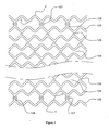
好ましい局面において、ステントの骨格構造は、正弦波形状を有するストラットの列によるパターンを含み、ただし、この場合、1つの列の頂点が他の列の谷と整列させられ、かつ、1つの列の谷が、中央部分では3番目毎の(そのような)位置で、また、末端部分ではすべての頂点および谷において、次の列の頂点と、直線状の橋かけストラットによってつながれる。 In a preferred aspect, the skeletal structure of the stent includes a pattern with rows of struts having a sinusoidal shape, where the vertices of one row are aligned with the valleys of the other row and A trough is connected by a straight bridging strut at every third (such) position in the central portion and at every vertex and trough at the end portion with the next row of vertices.
本発明によれば、上記アニーリング処理は、最大でも866hPa(650mmHg)〜933hPa(700mmHg)の真空のもと、3時間から4時間にまで及ぶ期間にわたって、100℃〜110℃の間の温度で行われ、その後には、ステントを25秒〜30秒で周囲温度に冷却することが続く。 According to the present invention, the annealing treatment is performed at a temperature between 100 ° C. and 110 ° C. over a period of time ranging from 3 hours to 4 hours under a vacuum of at most 866 hPa (650 mmHg) to 933 hPa (700 mmHg). Followed by cooling the stent to ambient temperature in 25-30 seconds.
さらに、アニーリング処理されたステントの清浄化は、ペルクロロエチレンそれ自体、もしくは、好適な溶媒で希釈されたペルクロロエチレン中での、又は、イソプロピルアルコールおよびクロロホルムの混合物中での、回転によって行われる。 Furthermore, the cleaned stent is cleaned by rotation in perchlorethylene itself, or in perchlorethylene diluted with a suitable solvent, or in a mixture of isopropyl alcohol and chloroform. .
本発明のプロセスでは、三軸楕円形状を有する白金から作製される6個の放射線不透明マーカが、ステントの末端部分の橋かけストラットに固定され、この場合、3個のマーカがステントのそれぞれの末端に固定され、ただし、前記マーカは、これらマーカにより、末端におけるステントの開存性と同様にステント位置の明瞭な見当が、OCTまたはIVUSの助けを借りることなく、2つの標準的な直交図で与えられるように互いに120°での等間隔で置かれる。 In the process of the present invention, six radio opaque markers made from platinum having a triaxial elliptical shape are secured to the bridging struts at the end portion of the stent, in which case three markers are attached to each end of the stent. However, the markers allow for a clear registration of the stent position as well as the patency of the stent at the end, in two standard orthogonal views without the help of OCT or IVUS. As given, they are spaced equidistant from each other at 120 °.
別の好ましい局面において、ステントは、生分解性ポリマーを伴うシロリムスの配合物(すなわち、50:50の割合(w/w)でのPDLLAおよびステントの1mm2の面積あたり1.25μgのシロリムス用量)により被覆される。その被覆は、スプレーコーティングを使用して行われる。 In another preferred aspect, the stent is a formulation of sirolimus with a biodegradable polymer (ie PDLLA at a 50:50 ratio (w / w) and a sirolimus dose of 1.25 μg per 1 mm 2 area of the stent) Is covered. The coating is done using spray coating.
さらに別の局面において、本発明は、被覆ステントまたは非被覆ステントのクリンピング(巻付け装着)を提供する。この方法によれば、被覆ステントまたは非被覆ステントが、清浄な雰囲気のもと、6段階〜8段階での25℃〜40℃および200秒〜310秒の滞留時間で送達カテーテルの事前に滅菌されたバルーンにクリンプ(巻付け装着)される。 In yet another aspect, the present invention provides crimping of a coated or uncoated stent. According to this method, a coated stent or an uncoated stent is pre-sterilized in a clean atmosphere with a 6 to 8 stage 25 ° C. to 40 ° C. and a residence time of 200 seconds to 310 seconds. Crimped on the balloon.
さらに別の局面において、ステントが、
(a)ステント以外の構成成分をETO滅菌プロセスに供すること;
(b)滅菌済みカテーテルのバルーンにおける非滅菌ステントを清浄な環境においてクリンプ(巻付け装着)すること;および
(c)ステントシステム全体を15℃〜25℃の間の温度で、6kGy〜12kGyの間(好ましくは6kGy〜10kGyの間)の線量におけるeビーム滅菌に供すること
によって滅菌される。
滅菌プロセスの期間中に、3cfu未満の生物汚染度および「6対数減少」(10−6)の滅菌保証レベル(SAL)が、旋光度または結晶化度に対する顕著な影響を何ら伴うことなく達成される。
In yet another aspect, the stent is
(A) subjecting components other than stents to the ETO sterilization process;
(B) crimping a non-sterile stent in a sterile catheter balloon in a clean environment; and (c) the entire stent system at a temperature between 15 ° C. and 25 ° C., between 6 kGy and 12 kGy. Sterilized by subjecting to e-beam sterilization at a dose (preferably between 6 kGy and 10 kGy).
During the sterilization process, a biofouling degree of less than 3 cfu and a sterility assurance level (SAL) of “6 log reduction” (10-6) is achieved without any significant effect on optical rotation or crystallinity. The
本発明のプロセスを使用することによって、ストラット厚さが100μm〜110μmであるステントを、ステントのサイズおよび適した疲労強度に応じて20N〜25Nの半径方向強さを伴って達成することができる。 By using the process of the present invention, a stent with a strut thickness of 100 μm to 110 μm can be achieved with a radial strength of 20 N to 25 N depending on the size of the stent and the appropriate fatigue strength.
従って、本発明は更に、薄いストラット(130μm以下のストラット厚さ、好ましくは100μm〜110μmのストラット厚さ)を高い疲労強度および半径方向強さとともに有する、生体吸収性ポリマーから作製されるバルーン拡張式ステントを包含する。 Accordingly, the present invention further provides a balloon expandable made from a bioabsorbable polymer having a thin strut (a strut thickness of 130 μm or less, preferably a strut thickness of 100 μm to 110 μm) with high fatigue strength and radial strength. Includes a stent.
本発明は、適した疲労強度および半径方向強さを小さいはね返りと同様に有する、薄いストラットの生分解性ステントで、適正な規格のPLLAポリマーのチューブから作製される生分解性ステント、ならびに、その製造方法を開示する。本発明の様々な実施形態により、ステントのポリマー特性および製造が記載される。本発明は、バルーン拡張式ステント、ステントグラフト、または、他の血管用途のためのステントに適用することができる。 The present invention is a thin strut biodegradable stent having a suitable fatigue strength and radial strength as well as a small bounce, made from a tube of the appropriate standard PLLA polymer, and its A manufacturing method is disclosed. Various embodiments of the present invention describe the polymer properties and manufacture of a stent. The present invention can be applied to balloon expandable stents, stent grafts, or stents for other vascular applications.
ポリマーの機械的特性は、主として平均分子量および分子量分布のような特徴に依存する。ポリマーは種々のサイズおよびタイプのモノマー鎖を有する。ポリマーの分子量が、重量平均分子量Mwおよび数平均分子量Mnによって記載されることが可能である。Mwは、鎖長が異なる同じタイプの個々の高分子を有するポリマーさえも含むポリマーの様々な分子鎖の平均分子量を表す。Mnは、様々なポリマー鎖の種々のサイズの平均を表し、個々の高分子の分子量の算術平均または相加平均である。MwおよびMnはゲル浸透クロマトグラフィー(GPC)によって求めることができる。ポリマーについてのもう1つの重要なパラメータが、Mw対Mnの比率(Mw/Mn)である多分散性指数(PDI)である。このパラメータは、分子分布がどのくらい狭いかの目安を与える。MwおよびMnに密接に関連づけられるパラメータが、Brookfield粘度計の形式LVDV E230を使用して測定された固有粘度である。 The mechanical properties of polymers depend mainly on characteristics such as average molecular weight and molecular weight distribution. The polymers have monomer chains of various sizes and types. The molecular weight of the polymer can be described by the weight average molecular weight Mw and the number average molecular weight Mn . M w represents the average molecular weight of the various molecular chains of the polymer, including even polymers with the same type of individual macromolecules with different chain lengths. M n represents the average of various sizes of the various polymer chains and is the arithmetic or arithmetic average of the molecular weights of the individual macromolecules. M w and M n can be determined by gel permeation chromatography (GPC). Another important parameter for the polymer is the polydispersity index (PDI), which is the ratio of M w to M n (M w / M n ). This parameter gives an indication of how narrow the molecular distribution is. A parameter closely related to M w and M n is the intrinsic viscosity measured using a Brookfield viscometer type LVDV E230.
加えて、さらに記載される様々な他のパラメータがポリマーのために重要である。ガラス転移温度Tgおよび融解温度Tmが重要な熱特性である。ポリマーを高い温度で加工すると、ポリマーの形態における変化が生じ、その結晶化度Xcが影響を受ける。Xcにより、ポリマーの結晶化度の程度が百分位の値で明らかにされる。全体的に非晶質のポリマーはXc値が0%であり、完全に結晶性のポリマーはXc値が100%である。より大きい微結晶性領域(より大きいXc)を有するポリマーは一般に、靭性および耐衝撃性が、より低い微結晶性領域(より低いXc)を有するポリマーよりも大きい。 In addition, various other parameters described further are important for the polymer. The glass transition temperature T g and the melting temperature T m is an important thermal properties. When the polymer is processed at high temperatures, changes in the polymer morphology occur and its crystallinity Xc is affected. Xc reveals the degree of crystallinity of the polymer in percentile values. The totally amorphous polymer has an Xc value of 0% and the completely crystalline polymer has an Xc value of 100%. Polymers with larger microcrystalline regions (greater X c ) are generally greater in toughness and impact resistance than polymers with lower microcrystalline regions (lower X c ).
PLLAは光学活性モノマーのポリマー形態であるので、PLLAの比旋光度もまた、重要な特徴である。光学活性モノマーから得られるポリマーは半結晶性であり、その一方で、光学不活性モノマーは非晶質ポリマーを与える。結晶性ポリマーは、上記で記載されるように、より大きい機械的特性および熱機械的特性を有する。機械的特性における違いが、S(−)キラル中心のみの存在によって特徴づけられるポリマー鎖の立体規則性に関連づけられる。例えば、ラクチドモノマーがラセミ化を受けて、meso−ラクチドを形成する傾向は、より高い温度におけるポリマーの光学純度に影響を与える可能性があり、したがって、より高い温度におけるポリマーの材料特性に影響を与える可能性がある。 Since PLLA is a polymer form of an optically active monomer, the specific rotation of PLLA is also an important feature. Polymers obtained from optically active monomers are semicrystalline, while optically inactive monomers give amorphous polymers. Crystalline polymers have greater mechanical and thermomechanical properties, as described above. Differences in mechanical properties are related to the stereoregularity of the polymer chain, which is characterized by the presence of only S (−) chiral centers. For example, the tendency of a lactide monomer to undergo racemization to form meso-lactide can affect the optical purity of the polymer at higher temperatures and therefore affect the material properties of the polymer at higher temperatures. There is a possibility to give.
これらすべての特徴が、ステントを作製するプロセスのために使用されるポリマーの機械的特性に影響を及ぼす。 All these features affect the mechanical properties of the polymers used for the process of making the stent.
本発明では、生体吸収性ステントを作製するために、様々な分子量のPLLA、PLGA、PDLAのような多数の生体吸収性ポリマーが検討された。MwおよびMnが並びに他の特徴もまた、ステント製造のそれぞれの工程において、すなわち、チューブの押出しから始まって滅菌までのそれぞれの工程において変化することが検討期間中に認められた。これらの特性を様々な加工条件のもとで観測することにより、小さいストラット厚さにもかかわらず、適した機械的強度を有する完成したステントを作製する際に役立った有益な洞察が得られた。特定の骨格設計もまた、小さいストラット厚さを達成する際に重要な役割を果たした。 In the present invention, a large number of bioabsorbable polymers such as PLLA, PLGA, PDLA of various molecular weights have been studied in order to produce bioabsorbable stents. It was observed during the study period that M w and M n as well as other characteristics also changed in each step of stent manufacture, ie, each step from tube extrusion to sterilization. Observing these properties under a variety of processing conditions has provided valuable insights that have helped in making finished stents with suitable mechanical strength, despite the small strut thickness. . Certain framework designs also played an important role in achieving small strut thickness.
ポリマーチューブは、押出しプロセスまたは成形プロセスを使用して形成される。押出しプロセスまたは成形プロセスの期間中において、PLLAは、ポリマーの分子量の低下を生じさせるラクチドモノマーおよび他の副生成物の形成を引き起こす熱分解を受ける可能性がある。PLLAの機械的特性がその分子量に依存することが十分に調べられている;強度が分子量における増大とともに増大する。ポリマーの分解はその平均分子量における低下を引き起こす。したがって、過度に高い温度は、ポリマーの分解を避けるために押出し期間中においては避けなければならない。チューブの押出しがポリマーのおよそ融点で行われる。平均分子量Mnだけでなく、平均分子量Mwにおける著しい低下が、すべてのタイプの生体吸収性ポリマーにおいて認められた。類似する条件のもとでは、Mwにおける%低下が押出しプロセス前のMwに依存していることが認められた。このことは、Mwにおける%低下が、より低いMwを有するポリマーと比較して、より大きいMwを有するポリマーについてはより大きかったことを意味する。例えば、押出し前および押出し後におけるPLLAのMwが765230および590780であることがそれぞれ見出され、これはMwにおける22.8%の低下に達した。Mwが622480である別のPLLAは類似条件のもと、押出し後には496490のMwを示し、すなわち、Mwが20.24%低下した。類似した結果がまた、PLGAチューブおよびPDLAチューブの場合において認められている。 The polymer tube is formed using an extrusion process or a molding process. During the extrusion or molding process, PLLA can undergo thermal degradation that results in the formation of lactide monomers and other byproducts that cause a decrease in the molecular weight of the polymer. It has been well investigated that the mechanical properties of PLLA depend on its molecular weight; strength increases with increasing molecular weight. Degradation of the polymer causes a decrease in its average molecular weight. Thus, excessively high temperatures must be avoided during the extrusion period to avoid polymer degradation. The tube is extruded at approximately the melting point of the polymer. Not only average molecular weight M n, a significant reduction in the average molecular weight M w of, was observed in all types of bioabsorbable polymers. Under similar conditions, it was observed that percent reduction in M w is dependent on the M w of the pre-extrusion process. This reduction% in M w of, as compared with a polymer having a lower Mw, meaning that was greater for polymers having greater M w. For example, the M w of PLLA before and after extrusion was found to be 765230 and 590780, respectively, which reached a 22.8% reduction in M w . Another PLLA with a Mw of 622480 showed a Mw of 494490 after extrusion under similar conditions, ie, the Mw was reduced by 20.24%. Similar results have also been observed in the case of PLGA and PDLA tubes.
上記場合の両方において、平均分子量Mnにおける%低下はMwよりも大きかった。前者の場合、Mnが563340から355280に低下し(すなわち、36.94%)、後者の場合は、Mnが459630から307720に低下した(すなわち、33.05%)。したがって、押出し条件は、有意な様式でポリマーの特性に影響を及ぼす可能性がある。押出しされたチューブの機械的特性がまた、押出しプロセスの期間中に加えられる応力および他のプロセスパラメータに依存していることに留意することもまた重要である。 In both cases, the% reduction in average molecular weight Mn was greater than Mw . In the former case, M n decreased from 563340 to 355280 (ie, 36.94%), and in the latter case, M n decreased from 459630 to 307720 (ie, 33.05%). Thus, extrusion conditions can affect the properties of the polymer in a significant manner. It is also important to note that the mechanical properties of the extruded tube are also dependent on stresses and other process parameters applied during the extrusion process.
ポリマーの様々な機械的特性がポリマー鎖の分子配向に依存する。ポリマー鎖の分子配向が、応力がポリマーに加えられたときに変化する。分子鎖の再配向が、加えられた応力の方向で生じる。ポリマー鎖の配向が変化する程度が、応力が加えられる温度および応力の大きさに依存する。一般には、分子配向を変化させるためには、この温度はポリマーのガラス転移温度(Tg)を超えて、その融点よりも低くなければならない。応力を、ポリマー分子を軸方向および円周方向に配向させるために軸方向および半径方向で加えることができる。 Various mechanical properties of the polymer depend on the molecular orientation of the polymer chain. The molecular orientation of the polymer chain changes when stress is applied to the polymer. Molecular chain reorientation occurs in the direction of the applied stress. The degree to which the orientation of the polymer chain changes depends on the temperature at which the stress is applied and the magnitude of the stress. In general, to change the molecular orientation, this temperature must be above the glass transition temperature (T g ) of the polymer and below its melting point. Stress can be applied in the axial and radial directions to orient the polymer molecules in the axial and circumferential directions.
応力を加えることはまた、ポリマーの結晶化度に影響を及ぼす。上述の通り、ポリマーの機械的特性はまた、その結晶化度に依存する。結晶化度はポリマーの機械的強度を増大させる。結晶化度はまた、ポリマーの分解速度に影響を及ぼす。結晶化度における増大は分解速度を低下させる。下記で記載される製造方法および骨格構造は、ポリマーとしてPLLAに関するものである。しかしながら、本発明の様々な局面は他のポリマーに対して適用することができ、当業者は、本発明の局面を生分解性および生体適合性の種々のポリマー材料のために最適化することによって本発明の局面を採用することができる。 Applying stress also affects the crystallinity of the polymer. As mentioned above, the mechanical properties of a polymer also depend on its crystallinity. Crystallinity increases the mechanical strength of the polymer. Crystallinity also affects the degradation rate of the polymer. An increase in crystallinity reduces the degradation rate. The manufacturing method and skeleton structure described below relate to PLLA as a polymer. However, various aspects of the present invention can be applied to other polymers, and those skilled in the art will be able to optimize aspects of the present invention for a variety of biodegradable and biocompatible polymer materials. Aspects of the present invention can be employed.
したがって、好ましい実施形態において、本発明は、下記で記載されるような、ポリマー(PLLA)ステントを製造するための詳細な方法を提供する:
(a)ポリマーチューブが押出し成形または射出成形によって作製される。プロセス条件および設備は、所望される内径diおよび外径doを有するチューブを生じさせなければならない。本発明では、ポリマーチューブが押出しプロセスによって作製され、ポリマーチューブのMwが590000から620000にまで及び、Mnが350000から370000にまで及び、結晶化度が7%から12%にまで及んだ。
(b)内径diおよび外径doを有する押出しされたポリマーチューブTが、(図1に示される)鋳型Mの中央に置かれる。鋳型Mは形状が円筒であり、良好な熱伝導率を有する金属から作製される。鋳型Mは、図1に示されるように内径DMを有する。ポリマーチューブTは、鋳型Mの両末端に提供される末端プラグPの使用によって鋳型の中心に調整させられる。末端プラグPの詳細が図2に示される。鋳型Mの内部におけるポリマーチューブTの一部がT’として示される。
(c)ポリマーチューブTの2つの末端(図1に示されるような近位側末端E1および遠位側末端E2)が固定具Fおよび固定具Cで鋳型の外側でしっかりと保持される。チューブTの遠位側末端が、チューブTのこの末端がクリンプされ、かつ、封止されるように固定具Cに固定される。両方の固定具(FおよびC)は、チューブTに対して軸方向に伝えられる軸方向の力FAを両方の固定具に等しく加えることによって移動させることができる。
(d)チューブTの近位側末端E1が、不活性ガスをチューブTの内部に加圧下で供給することができる(図1に示されるように)不活性ガスの供給源Gにつながれる。
(e)鋳型Mが、加熱および冷却のための配置を有する(図1に示される)ジャケットJによって覆われる。加熱が電気的に行われ、冷却が、好適な冷却媒体によって行われる。ジャケットJは鋳型Mの加熱および冷却を行い、これにより、結果として、ポリマーチューブTが加熱され、また、冷却される。この加熱・冷却システムは、鋳型MおよびチューブT’の加熱または冷却を均一に行うことができる。鋳型の大きい熱伝導率は、ジャケットJ、鋳型Mおよび鋳型内部のチューブT’のための均一な熱移動において役立つ。温度表示器が、鋳型Mにおける温度を示すための重要な場所に提供される。
(f)電気的加熱がジャケットJにおいて始動され、チューブT’が70℃〜80℃の間(好ましくは74℃〜76℃の間)の温度に加熱される。
(g)その後、チューブTは、引張り力FAを両方の固定具(FおよびC)に加えることによって軸方向に変形させられる(伸張させられる)。鋳型Mの内部にあるチューブの一部(T’)の温度はチューブの残部(T)よりも高い。したがって、この一部分は、軸方向に変形することを開始することになり、すなわち、その長さが増大することになる。軸方向の力が、チューブT’の所望される伸張が達成されるまで加えられる。チューブの最終長さの、その初期長さに対する比率が、「軸方向拡張比」と呼ばれる。この比は1.4〜1.7の間で保たれる。
(h)この段階での鋳型における条件(引張り力および温度)が、チューブ状態を整えるために15秒〜20秒間にわたって保持される。その後、引張り力が除かれる。
(i)その後、不活性ガス供給源Gからの加圧下での窒素のような不活性ガスが、温度を維持しながら、チューブにその近位側末端E1を介して導入される。チューブTの遠位側末端E2がCにおいてクリンプされ、かつ、封止されるので、チューブT/T’における圧力が増大することになる。鋳型Mの内部にあるチューブの一部(T’)の温度はチューブの残部(T)よりも高い。したがって、この一部分は、半径方向に変形することを開始することになり、すなわち、その直径が増大することになる。不活性ガス圧が2段階またはそれ以上の段階で加えられ、好ましくは3段階で加えられる。不活性ガス圧を段階毎に加えることにより、機械的特性がさらに改善され、はね返りがかなり軽減され、かつ、変形させられたチューブT’の表面における亀裂および波打ち形成の可能性が排除される。変形させられたチューブT’の外径が、図3に示されるように、チューブの外側表面が鋳型Mの内側表面と接触するまで増大することになる。鋳型Mの内径(DM)により、チューブT’の変形の程度が制限される。チューブT’の内径および外径が、図3に示されるように、DiおよびDoにまでそれぞれ増大することになる。拡張させられたチューブの内径Diの、元のチューブ直径diに対する比率が、「半径方向変形比」と呼ばれる。Doが鋳型の内径DMに依存している。したがって、鋳型Mの内径(DM)は、所望される半径方向変形比が達成されるように保たれる。半径方向変形比が3〜5の間で保たれる。
Accordingly, in a preferred embodiment, the present invention provides a detailed method for making a polymer (PLLA) stent, as described below:
(A) A polymer tube is produced by extrusion molding or injection molding. The process conditions and equipment should produce a tube having a desired inner diameter d i and outside diameter d o. In the present invention, the polymer tube was made by an extrusion process, the polymer tube M w ranged from 590000 to 620000, the M n ranged from 350,000 to 370000, and the crystallinity ranged from 7% to 12%. .
(B) an inner diameter d i and extruded polymer tube T having outer diameter d o is, (shown in Figure 1) is placed in the center of the mold M. The mold M is cylindrical in shape and is made from a metal having good thermal conductivity. Mold M has an internal diameter D M as shown in FIG. The polymer tube T is adjusted to the center of the mold by the use of end plugs P provided at both ends of the mold M. Details of the end plug P are shown in FIG. A portion of the polymer tube T inside the mold M is shown as T ′.
(C) The two ends of the polymer tube T (proximal end E1 and distal end E2 as shown in FIG. 1) are firmly held outside the mold with fixtures F and C. The distal end of tube T is secured to fixture C so that this end of tube T is crimped and sealed. Both fasteners (F and C), can be moved by applying equal forces F A in the axial direction is transmitted in the axial direction with respect to the tube T to both fixtures.
(D) The proximal end E1 of the tube T is connected to a source G of inert gas (as shown in FIG. 1) that can supply the inert gas inside the tube T under pressure.
(E) The mold M is covered by a jacket J (shown in FIG. 1) having an arrangement for heating and cooling. Heating is effected electrically and cooling is effected by a suitable cooling medium. The jacket J heats and cools the mold M, and as a result, the polymer tube T is heated and cooled. This heating / cooling system can uniformly heat or cool the mold M and the tube T ′. The large thermal conductivity of the mold helps in uniform heat transfer for the jacket J, mold M and tube T ′ inside the mold. A temperature indicator is provided at an important location for indicating the temperature in the mold M.
(F) Electrical heating is initiated in jacket J and tube T ′ is heated to a temperature between 70 ° C. and 80 ° C. (preferably between 74 ° C. and 76 ° C.).
(G) The tube T is then deformed (stretched) in the axial direction by applying a tensile force F A to both fixtures (F and C). The temperature of a part (T ′) of the tube inside the mold M is higher than the remaining part (T) of the tube. This part will therefore begin to deform axially, i.e. its length will increase. An axial force is applied until the desired stretching of the tube T ′ is achieved. The ratio of the final length of the tube to its initial length is called the “axial expansion ratio”. This ratio is kept between 1.4 and 1.7.
(H) The conditions (tensile force and temperature) in the mold at this stage are maintained for 15-20 seconds to condition the tube. Thereafter, the tensile force is removed.
(I) An inert gas such as nitrogen under pressure from an inert gas source G is then introduced into the tube via its proximal end E1 while maintaining the temperature. Since the distal end E2 of the tube T is crimped and sealed at C, the pressure at the tube T / T ′ will increase. The temperature of a part (T ′) of the tube inside the mold M is higher than the remaining part (T) of the tube. This part will therefore begin to deform radially, i.e. its diameter will increase. Inert gas pressure is applied in two or more stages, preferably in three stages. By applying an inert gas pressure step by step, the mechanical properties are further improved, the rebound is significantly reduced, and the possibility of cracking and undulation on the surface of the deformed tube T ′ is eliminated. The outer diameter of the deformed tube T ′ will increase until the outer surface of the tube contacts the inner surface of the mold M, as shown in FIG. The inner diameter (D M ) of the mold M limits the degree of deformation of the tube T ′. Inner and outer diameters of the tube T 'is, as shown in FIG. 3, will increase respectively to the D i and D o. The ratio of the expanded tube inner diameter D i to the original tube diameter d i is called the “radial deformation ratio”. D o is dependent on the inner diameter D M of the mold. Thus, the inner diameter (D M ) of the mold M is maintained so that the desired radial deformation ratio is achieved. The radial deformation ratio is kept between 3-5.
鋳型Mにおける不活性ガス圧および温度が、状態を整えるためにそれぞれの段階の後で15秒間〜20秒間にわたって維持される。
チューブにおける不活性ガス圧を維持しながら、チューブの温度が、チューブの一貫した特性を達成するために上げられ、特定の期間にわたって維持される。その後、冷却媒体が、鋳型Mおよび変形させられたチューブT’を冷却するためにジャケットJに導入され、その後、変形させられたチューブT’が鋳型Mから取り出される。
(j)その後、変形させられたチューブが、ステント骨格構造をチューブに形成するためにレーザ装置で切削(カット)される。
(k)その後、放射線不透明マーカがステントに固定される。
(l)その後、放射線不透明マーカを有するレーザ切削されたステントが、骨格全体にわたる一貫したポリマー形態を得るために真空下でアニーリング処理される。この工程は、残留モノマーを除くことおよび特性のロット間変動の低減を助けている。この工程の目的は、結晶化度を増大させることではない。ポリマーの結晶化度における変化がこの工程の期間中にはほとんど認められない。
(m)その後、ステントは、どのような表面不規則をも除き、かつ、平滑な表面を達成するための好適な溶媒により清浄化(洗浄)され、その後、溶媒が真空下で除かれる。
(n)その後、ステントは、抗増殖性薬物のような治療剤の配合物で被覆される。
(o)その後、ステントは25℃〜40℃の間で送達デバイス(すなわち、カテーテル)にクリンプされる。
(p)その後、クリンプされたステントは送達システムと一緒に、eビームを使用して滅菌される。
The inert gas pressure and temperature in the mold M are maintained for 15 to 20 seconds after each stage to condition.
While maintaining the inert gas pressure in the tube, the temperature of the tube is raised to achieve a consistent characteristic of the tube and maintained for a specified period of time. A cooling medium is then introduced into the jacket J to cool the mold M and the deformed tube T ′, after which the deformed tube T ′ is removed from the mold M.
(J) The deformed tube is then cut (cut) with a laser device to form the stent skeleton structure into the tube.
(K) A radiation opaque marker is then secured to the stent.
(L) The laser-cut stent with the radiation opaque marker is then annealed under vacuum to obtain a consistent polymer morphology throughout the scaffold. This process helps remove residual monomer and reduce lot-to-lot variation in properties. The purpose of this step is not to increase crystallinity. Little change in the crystallinity of the polymer is observed during this process.
(M) The stent is then cleaned (washed) with a suitable solvent to remove any surface irregularities and achieve a smooth surface, after which the solvent is removed under vacuum.
(N) The stent is then coated with a formulation of a therapeutic agent such as an antiproliferative drug.
(O) The stent is then crimped to a delivery device (ie, a catheter) between 25 ° C and 40 ° C.
(P) The crimped stent is then sterilized using an e-beam along with the delivery system.
上記で記載されるそれぞれの製造工程が、分子量、結晶化度、分子配向などのようなポリマー特性に影響する。このことは結果として、ポリマーの機械的特性を変化させる。完成したステントの機械的特性は、十分な半径方向強さおよび疲労強度を低いはね返りと同様に明らかにするために適正でなければならない。ステントは、所望される分解速度を有しなければならず、その結果、ステントは、血管が治癒されるまでは血管に対する適した支持を提供し、かつ、最終的にはインプラント部位から消失するようにしなければならない。 Each manufacturing process described above affects polymer properties such as molecular weight, crystallinity, molecular orientation and the like. This results in changing the mechanical properties of the polymer. The mechanical properties of the finished stent must be adequate to reveal sufficient radial strength and fatigue strength as well as low rebound. The stent must have the desired rate of degradation so that the stent provides suitable support for the blood vessel until it is healed and eventually disappears from the implant site. Must be.
軸方向および半径方向の変形のために、チューブの長さおよび直径は変化を受ける。したがって、チューブの厚さが変化することになる。変形させられたチューブT’の厚さは元のチューブTの厚さよりも小さくなるであろう。所望される厚さのステントを得るために、変形させられたチューブの厚さは、特定の内径および外径(diおよびdo)を有する元のチューブT、ならびに、加工された(変形させられた)チューブの所望される大きさ(DiおよびDo)を得るための変形比を選定することによって制御されなければならない。これらの大きさにより、完成したステント骨格のストラット厚さが決定される。 Due to axial and radial deformation, the length and diameter of the tube are subject to change. Therefore, the thickness of the tube changes. The thickness of the deformed tube T ′ will be smaller than the thickness of the original tube T. In order to obtain the desired thickness of the stent, the thickness of the tube is deformed, the original tube T having a certain inner diameter and an outer diameter (d i and d o), and, then processed (deformed And) must be controlled by selecting a deformation ratio to obtain the desired size of the tube (D i and D o ). These dimensions determine the strut thickness of the completed stent framework.
チューブを変形させるために使用される管状鋳型は、非常に良好な熱伝導率を有する高規格のベリリウム銅のような金属から作製される。 The tubular mold used to deform the tube is made from a metal such as high grade beryllium copper with very good thermal conductivity.
簡便な末端プラグPが、チューブを鋳型の中央に保つために鋳型の両末端で使用される。プラグPの詳細が図2に示される。このことにより、鋳型におけるチューブの均一な軸方向および半径方向の拡張を保証するチューブの均一な加熱がもたらされる。このことは結果として、変形させられたチューブの均一な厚さをもたらす。この目的のために、鋳型表面を制御された速度で端から端まで並進する熱源のような複雑な装置構成の使用は必要とされない。 A simple end plug P is used at both ends of the template to keep the tube in the middle of the template. Details of the plug P are shown in FIG. This results in uniform heating of the tube that ensures uniform axial and radial expansion of the tube in the mold. This results in a uniform thickness of the deformed tube. For this purpose, the use of complex equipment configurations such as heat sources that translate the mold surface at a controlled rate from end to end is not required.
具体的な実施形態において、不活性ガスの圧力が三段階でチューブに加えられる:すなわち、第1段階における1.72MPa(250psi)〜1.93MPa(280psi)、続いて第2段階における2.58MPa(375psi)〜2.82MPa(410psi)、最後は第3段階における3.44MPa(500psi)〜3.65MPa(530psi))。温度が70℃〜80℃の間で維持され、好ましくは74℃〜76℃の間で維持される。そのような比較的より大きい圧力が段階毎に加えられることにより、厳しい許容差を伴うチューブT’の変形と、亀裂および波打った表面が除かれることとが保証される。それぞれの段階の後で、条件(圧力および温度)が、チューブをこれらの条件のもとで整えるために15秒〜20秒の間で変化する期間にわたって維持される。 In a specific embodiment, the inert gas pressure is applied to the tube in three stages: from 1.72 MPa (250 psi) to 1.93 MPa (280 psi) in the first stage, followed by 2.58 MPa in the second stage. (375 psi) to 2.82 MPa (410 psi) and finally 3.44 MPa (500 psi) to 3.65 MPa (530 psi) in the third stage). The temperature is maintained between 70 ° C and 80 ° C, preferably between 74 ° C and 76 ° C. Such relatively greater pressure is applied step by step to ensure that the deformation of the tube T 'with tight tolerances and that cracks and wavy surfaces are removed. After each stage, the conditions (pressure and temperature) are maintained over a period that varies between 15 and 20 seconds to condition the tube under these conditions.
最後の段階の圧力、すなわち、3.44MPa(500psi)〜3.65MPa(530psi)を維持しながら、チューブは90℃〜120℃の間(好ましくは100℃〜110℃の間)の温度に加熱され、30秒間〜2分間にわたって維持される。その後、チューブは20秒〜30秒で20℃に冷却される。その後、圧力が開放され、その後、チューブが鋳型から取り出される。この段階におけるチューブは、一貫した特性を達成している。この段階における結晶化度は45%未満である。 The tube is heated to a temperature between 90 ° C. and 120 ° C. (preferably between 100 ° C. and 110 ° C.) while maintaining the last stage pressure, ie, 3.44 MPa (500 psi) to 3.65 MPa (530 psi). And maintained for 30 seconds to 2 minutes. The tube is then cooled to 20 ° C. in 20-30 seconds. The pressure is then released and then the tube is removed from the mold. The tube at this stage achieves consistent properties. The crystallinity at this stage is less than 45%.
チューブの三段階加圧は、一段階を上回る利点をもたらす。アニーリング処理後でのMwおよびMnにおける全体的な%低下が、一段階加圧と比較して、三段階加圧の場合にはより小さかった。多分散性指数PDIが、狭い分子量分布を示した一段階と比較して、三段階プロセスの場合にはより小さくなった。三段階加圧は、厳しい許容差を有し、かつ、亀裂および波打った表面を有しない変形させられたチューブをもたらした。 Three-stage pressurization of the tube provides advantages over one stage. The overall% reduction in M w and M n after the annealing treatment was smaller with the three-stage pressurization compared to the single-stage pressurization. The polydispersity index PDI was smaller for the three-stage process compared to the one stage that showed a narrow molecular weight distribution. Three-stage pressurization resulted in a deformed tube with tight tolerances and no cracks and wavy surfaces.
さらに別の実施形態において、変形させられたチューブのレーザ切削が、ポリマー骨格を加工されたチューブにおいて切削するために、フェムト秒の設備および1300nm〜1600nmの波長のレーザビームを使用して行われる。このレーザ切削プロセスは、レーザ切削プロセスによってチューブに形成される構造要素であるストラットからなってもよいステント骨格パターンをもたらす。半径方向拡張の後におけるチューブの直径が、チューブの最初の直径(di/do)と、完成したステントの広げられた直径との間である場合がある。ステントの骨格構造は、リングを形成する円筒状要素と呼ばれることがあるその円周全体での様々な幾何学的形状の、半径方向に広がり得る反復する列を有する。要素の形状、および、そのような要素が互いに相互につながれる様式は、種々の構造的特性を達成するために、すなわち、血管腔壁によってステント構造物に加えられる半径方向の力に対する抵抗を与える機械的強度を達成するために操作することができる。種々の形状を作り出すことにおける大きな設計柔軟性が存在する。この柔軟性は、ステントの他の望ましい特性を念頭において使用されなければならない。ステント構造が、これらの要素を、ストラットの特定の形状および相互につながれた配列を形成するための特定のパターンで設置することによって形成される。このパターンにおける要素は、ステントが拡張したときには、プラークまたは身体管腔の解離部が管腔の壁に対して適所に効果的に押しつけ返され、これにより、組織の逸脱を防止するための適した支持を与えるように十分に接近していなければならない。同時に、これらの要素は、柔軟性に悪影響を及ぼすほどに、ステントがカテーテルのバルーンにクリンプされている期間中に互いに干渉するほどに、または、血管腔における側枝への不適切なアクセスを示すほどに接近していてはならない。設計は、要求された半径方向強さおよび疲れ抵抗(疲労耐性)強さをステントに与えるために十分に堅くなければならない。要素は、十分な塑性変形を、弾性はね返りが許容可能限界の範囲内にあるように指定圧力での拡張のときに受けなければならない。ステントが半径方向に拡張させられるときには、その直径が増大し、これにより、その長さにおける変化が生じる。要素の形状および配置は、元の長さを可能な限り維持し、これにより、ステント長さを許容可能限界の範囲内に保つために、ステント長さにおけるこの変化を打ち消さなければならない。このことが、特定のストラット要素が半径方向拡張と一致して伸張することを生じさせることによって達成される。ステントの種々の区域が異なる機械的強度をその軸の全体にわたって有することがあるにもかかわらず、ステントは、その指定された直径を、定格の展開圧がバルーンカテーテルに加えられるときにはその全長の端から端まで均一に達成しなければならない。設計は、送達(搬送)期間中に外れることを阻止し、また、ステントを身体管腔の患部で拡張させた後におけるはね返りを最小限に抑えるためにカテーテルのバルーンにおけるクリンプされたステントの十分な把持を提供しなければならない。骨格構造は、ステントが、側枝を有する管腔に留置されたときには再介入を可能にしなければならない。すなわち、ステントは、適正な側枝アクセスを提供しなければならない。そのような場合、ステントを伴う、または伴わない別のカテーテルが、留置されたステントのストラットを介して挿入されるときには、構造的セルにより、十分に大きい開口部が、ストラットを壊すことなくもたらされなければならない。構造は、カテーテルのバルーンにおけるクリンピング、血管腔を介して操ること、患部における拡張/展開、および、血管腔によって誘発される周期的力のすべての力に耐えるための適した強さおよび柔軟性を有しなければならない。 In yet another embodiment, laser cutting of the deformed tube is performed using femtosecond equipment and a laser beam with a wavelength between 1300 nm and 1600 nm to cut the polymer backbone in the processed tube. This laser cutting process results in a stent framework pattern that may consist of struts, which are structural elements formed in the tube by the laser cutting process. The tube diameter after radial expansion may be between the initial diameter of the tube (d i / d o ) and the expanded diameter of the finished stent. The skeletal structure of a stent has repeating rows of various geometric shapes that may be referred to as cylindrical elements that form a ring, and that may extend radially. The shape of the element and the manner in which such elements are interconnected provides resistance to the radial forces applied to the stent structure by the vessel lumen wall, ie, to achieve various structural properties Can be manipulated to achieve mechanical strength. There is great design flexibility in creating various shapes. This flexibility must be used with other desirable properties of the stent in mind. A stent structure is formed by placing these elements in a specific pattern to form a specific shape of struts and interconnected arrays. The elements in this pattern are suitable for preventing plaque detachment as the plaque or body lumen dissociation is effectively pushed back into place against the lumen wall when the stent is expanded. Must be close enough to give support. At the same time, these elements can have an adverse effect on flexibility, interfere with each other while the stent is crimped onto the catheter balloon, or exhibit inappropriate access to the side branches in the vessel lumen Must not be close to The design must be stiff enough to give the stent the required radial strength and fatigue resistance (fatigue resistance) strength. The element must undergo sufficient plastic deformation when expanded at the specified pressure so that the elastic rebound is within acceptable limits. As the stent is radially expanded, its diameter increases, which causes a change in its length. The shape and placement of the elements must counter this change in stent length in order to maintain the original length as much as possible, thereby keeping the stent length within acceptable limits. This is accomplished by causing certain strut elements to stretch in line with radial expansion. Despite the fact that various sections of the stent may have different mechanical strengths throughout their axis, the stent will have its specified diameter at the end of its full length when a rated deployment pressure is applied to the balloon catheter. Must be achieved uniformly from end to end. The design is sufficient for crimped stents in the catheter balloon to prevent dislodgement during delivery (carrying) and to minimize rebound after the stent is expanded in the affected area of the body lumen. A grip must be provided. The skeletal structure should allow re-intervention when the stent is placed in a lumen with side branches. That is, the stent must provide proper side branch access. In such a case, when another catheter with or without a stent is inserted through the strut of the deployed stent, the structural cell provides a sufficiently large opening without breaking the strut. It must be. The structure provides adequate strength and flexibility to withstand all the forces of crimping in the balloon of the catheter, maneuvering through the vessel lumen, dilatation / deployment in the affected area, and periodic forces induced by the vessel lumen. Must have.
ステントは、リングを形成する円筒状要素またはストラットの列を有する。これらの円筒状要素は、橋かけ要素または橋かけストラットによって相互につながれる。2つの連続する円筒状要素と、2つの連続する橋かけ要素との内側に形成される形状により、「セル」または「セル構造」が形成される。そのような要素が互いに相互につながれる様式は、種々の構造的特性を達成するために操作することができる。設計柔軟性が、様々な長さおよび幅を有するこれらのセルを作製することによって達成される。より大きい長さおよび幅を有するセルは、より低い強度を与えるであろう。他方で、より短い長さおよび幅を有するセルは、より大きい強度を与えるであろう。同じストラット厚さについては、より大きい幅を有するストラットは、より小さい幅のストラットと比較して、より大きい強度を有し、かつ、より大きい抵抗を動脈壁の圧縮力に対して与えることになる。用語「要素」および用語「ストラット」は、本明細書全体を通して交換可能に使用される。 The stent has a cylindrical element or row of struts forming a ring. These cylindrical elements are interconnected by bridging elements or bridging struts. A shape formed inside two continuous cylindrical elements and two continuous bridging elements forms a “cell” or “cell structure”. The manner in which such elements are interconnected can be manipulated to achieve a variety of structural properties. Design flexibility is achieved by making these cells with varying lengths and widths. Cells with larger lengths and widths will give lower strength. On the other hand, cells with shorter lengths and widths will give greater strength. For the same strut thickness, a strut with a larger width will have greater strength and provide greater resistance to the compressive force of the arterial wall compared to a strut with a smaller width. . The terms “element” and “strut” are used interchangeably throughout this specification.
本発明のステントの骨格構造は一般に、複数の頂上および谷をステントのその軸方向長さの全体にわたって有する規則的または不規則な形状を有する正弦波型円筒状要素の多数の列からなる。セルが、円筒状要素の上方列および下方列を直線状または湾曲状の連結具(「橋かけ要素」または「橋かけストラット」)によりつなぐことによって形成される。これらの橋かけ要素により、円筒状要素の上方列および下方列がこれらの要素の側面の長さに沿ってどこでもつながれる。これらの相互接続により、ステントの円筒状骨格構造が形成される。 The stent framework of the present invention generally consists of multiple rows of sinusoidal cylindrical elements having a regular or irregular shape with a plurality of peaks and valleys throughout the axial length of the stent. A cell is formed by connecting the upper and lower rows of cylindrical elements by straight or curved connectors ("bridge elements" or "bridge struts"). These bridging elements connect the upper and lower rows of cylindrical elements where along the length of the sides of these elements. These interconnections form the cylindrical skeletal structure of the stent.
橋かけストラットにより、柔軟性が、ステントを身体管腔の湾曲経路および蛇行経路において容易に操るためにステントに与えられる。不規則な曲線的円筒状要素の構造的強さを、橋かけストラットが要素の長さに沿って取り付けられる場所を変更することによって変化させることができる。本発明において記載される実施形態では、これらの連結が、要素の頂上および谷に、または、要素のそれぞれの側面の中央の近くに位置する。個々のストラットの幅および形状ならびにセルが、効果的なクリンピングを提供するように、十分な半径方向強さを拡張状態で与えるように、また、同時に、はね返りおよび長さにおける変化を許容可能限界の範囲内に保つように設計される。拡張後の骨格構造により、許容可能な側枝アクセスが与えられる。不規則な曲線的線状構造は、様々な程度の曲率を頂上および谷の領域において有する。曲率を、種々の構造的強さを与えるために変化させることができる。形状は、均一かつ小さいクリンプされた外形、同様にまた、ステントの円周の周りでの個々の要素の均一な半径方向拡張を、ステントの軸に沿って所与の区域において、また、個々の層において与えなければならない。定格の展開圧力がカテーテルのバルーンを介してステントに加えられるとき、ステントは、軸方向に要素の強度差を有するにもかかわらず、均一な直径をその全長にわたって達成する。 The bridging struts provide flexibility to the stent for easy manipulation of the stent in the curved and tortuous paths of the body lumen. The structural strength of irregular curvilinear cylindrical elements can be varied by changing where the bridging struts are attached along the length of the element. In the embodiments described in the present invention, these connections are located at the top and trough of the element or near the center of each side of the element. The width and shape of the individual struts as well as the cells provide sufficient radial strength in an expanded state to provide effective crimping, and at the same time allow changes in rebound and length to an acceptable limit. Designed to keep within range. The expanded skeletal structure provides acceptable side branch access. Irregular curvilinear linear structures have varying degrees of curvature in the top and valley regions. The curvature can be varied to provide various structural strengths. The shape is uniform and small crimped profile, as well as uniform radial expansion of individual elements around the circumference of the stent, in a given area along the stent axis Must be given in layers. When a rated deployment pressure is applied to the stent via the catheter balloon, the stent achieves a uniform diameter over its entire length despite having an elemental strength difference in the axial direction.
正弦曲線状の骨格構造は、大きい柔軟性を有する区間を与えるために、ストラットおよび直線状または湾曲状の接続リンクにより設計される。ステントがその展開期間中に拡張されると、これらの区間が、クリンプされた直径から、拡大された拡張時の直径にまで円周方向に変形する。種々の半径方向拡張特徴を、正弦曲線状要素および橋かけストラットのサイズ、形状および断面を変化させることによって得ることができる。加えて、ステントの半径方向強さを、列におけるセルの数を増大することによって増大させることができる。同様に、セルの強さを、橋かけストラットの数および幅を増大することによって増大させることができる。橋かけストラットがセルの上方列および下方列をつなぐ場所もまた、ステントの強度および全体的な柔軟性を増大させるために操作することができる。 A sinusoidal skeletal structure is designed with struts and straight or curved connecting links to give sections with great flexibility. As the stent is expanded during its deployment, these sections deform circumferentially from the crimped diameter to the expanded expanded diameter. Various radial expansion features can be obtained by changing the size, shape and cross-section of the sinusoidal elements and the bridging struts. In addition, the radial strength of the stent can be increased by increasing the number of cells in the row. Similarly, cell strength can be increased by increasing the number and width of cross-linked struts. The location where the bridging struts connect the upper and lower rows of cells can also be manipulated to increase the strength and overall flexibility of the stent.
セルの形状を、その側面の曲率を変化させることによって変化させることができる。ある極限において、セルには直線の形状を与えることができる。そのような変化はセルの全体的な強度における違いを生じさせることができ、したがって、全体として列およびステント構造の強度における違いを生じさせることができる。 The shape of the cell can be changed by changing the curvature of its side. In some limits, the cells can be given a straight shape. Such changes can make a difference in the overall strength of the cells, and thus can make a difference in the strength of the row and stent structure as a whole.
ステントの相互につながれた骨格構造の幾何形状は、拡張したときの弾性はね返りおよびステントの長さにおける変化が許容可能限界の範囲内に保たれるように設計される。 The geometry of the interconnected skeletal structure of the stent is designed so that elastic bounce when expanded and changes in stent length are kept within acceptable limits.
セルを形成するための要素の列の数が、ステントの全長によって決定される。クラウンとして定義されるところの、ステントの円周に沿った列におけるセルの数が、ステントの直径およびセルの幅によって決定される。クラウンの数を、クリンピング外形とのバランスを保って変化させることができる。 The number of rows of elements to form a cell is determined by the total length of the stent. The number of cells in a row along the circumference of the stent, defined as the crown, is determined by the stent diameter and cell width. The number of crowns can be varied in balance with the crimping profile.
ステントの全体的構成により、ステントの半径方向強さ、柔軟性および疲れ抵抗(疲労耐性)が決定される。それぞれのセルの大きさおよびそれらの間隔が、プラーク、および、ステントが留置される身体管腔のどのような部分もが突き出ることを防止するために十分に接近して調節される。同時に、これらの大きさは、カテーテルのバルーンを覆うステントの、問題のないクリンピングを、ステントの柔軟性を損なうことなく達成するために調節される。間隔もまた、所望される側枝アクセスを与えるために調節される。この構成は、ステントが完全に拡張させられた後、管腔壁がステントストラットにより均一に覆われることを与える。ステントが身体管腔に申し分なく、かつ、しっかりと配置される。展開期間中に、様々な区画の個々の要素が、全体的な骨格構造を変形させることなく、隣接する円筒状要素に対してわずかに乱されることがある。ステント拡張後、要素の様々な部分が外側にわずかに傾き、ステントを身体管腔において適切に配置するために少し血管壁に埋め込まれる場合がある。このことは、ステントを拡張後に所定の位置にしっかりと併置することを助ける。 The overall configuration of the stent determines the radial strength, flexibility and fatigue resistance (fatigue resistance) of the stent. The size of each cell and their spacing are adjusted close enough to prevent the plaque and any part of the body lumen in which the stent is placed from protruding. At the same time, these sizes are adjusted to achieve problem-free crimping of the stent covering the catheter balloon without compromising stent flexibility. The spacing is also adjusted to provide the desired side branch access. This configuration provides that the lumen wall is uniformly covered by the stent struts after the stent is fully expanded. The stent is perfectly and securely placed in the body lumen. During deployment, the individual elements of the various compartments may be slightly disturbed relative to the adjacent cylindrical elements without deforming the overall skeletal structure. After stent expansion, various portions of the element may tilt slightly outward and may be slightly embedded in the vessel wall to properly place the stent in the body lumen. This helps to place the stent firmly in place after expansion.
個々のセルの構成、橋かけ要素およびそれらの相互接続が、クリンピングおよび拡張の期間中の応力をステント全体にわたって均一に分布させるために設計される。 Individual cell configurations, bridging elements and their interconnections are designed to evenly distribute the stress during crimping and expansion throughout the stent.
セルを互いに相互に接続することが、上記で記載されるような橋かけ要素によって達成される。これらの連結が、セルの正弦波型形状を形成する要素の頂点または谷のどちらかでつながれる。これらの連結はまた、セルの正弦波型形状を形成する要素の側面の中央の近くでもつなぐことができる。このことにより、支持されていない長さが、橋かけされたトラス桁梁のような橋かけ要素の接続点において減少する、十分に支持された構造的梁の形態である構造が得られる。橋かけ要素はまた、セルの側面要素に対して偏ってつなぐことができる。このことはこの要素の支持されていない長さを3つの区画に分けることになる。これらの要素の支持されていない長さはこれらの橋かけ要素の位置に依存する。セルの要素は、完全な塑性変形を、弾性はね返りを許容可能限界の範囲内に十分に保つために拡張後に受ける。 Interconnecting the cells to each other is accomplished by a bridging element as described above. These connections are connected either at the vertices or valleys of the elements that form the sinusoidal shape of the cell. These connections can also be connected near the center of the side of the element forming the sinusoidal shape of the cell. This results in a structure that is in the form of a fully supported structural beam in which the unsupported length is reduced at the connection points of the bridging elements such as bridged truss beams. The bridging element can also be biased against the side elements of the cell. This divides the unsupported length of this element into three sections. The unsupported length of these elements depends on the position of these bridging elements. The elements of the cell undergo full plastic deformation after expansion to keep the elastic bounce well within acceptable limits.
上記で記載されるステント骨格構造の構成により、ステント設計者に対しての十分な自由が、ステントの要素の形状および他の大きさを変更して、必要な半径方向強さをステント構造に与えるステントストラットの厚さを効果的に減らし、また、所望される疲れ抵抗(疲労耐性)を得るために与えられる。上記で記載されるように、ステントの低下した厚さにより、身体管腔の壁に対する傷害が軽減されることは、広く受け入れられている事実である。 Due to the configuration of the stent framework described above, sufficient freedom for the stent designer can alter the shape and other dimensions of the stent elements to give the stent structure the required radial strength. It is provided to effectively reduce the thickness of the stent struts and to obtain the desired fatigue resistance (fatigue resistance). As described above, it is a widely accepted fact that reduced thickness of the stent reduces injury to the body lumen wall.
ステントの柔軟性が、ステントの円周の全体にわたる橋かけ要素の厚さおよび数ならびにそれらの場所によって決定される。これらの接続具の数が減らされるならば、正弦曲線状区域の一部が自由になって、より柔軟性をステントに与える。しかしながら、このことはステントの機械的強度を低下させることになる。したがって、ステントの全体的な特性を最適化するために、柔軟性と強度との間でバランスを取ることが極めて重要である。 Stent flexibility is determined by the thickness and number of bridging elements and their location throughout the circumference of the stent. If the number of these connectors is reduced, some of the sinusoidal area is freed to give the stent more flexibility. However, this will reduce the mechanical strength of the stent. Therefore, it is very important to balance between flexibility and strength in order to optimize the overall properties of the stent.
本発明の具体的な実施形態において記載されるステントの設計は、上記で記載される原理に基づいており、一般には冠動脈血管系のためのものである。しかしながら、本発明において記載される構成は、ステントの種々の形状を得るために変更することができ、その結果、脳血管系、腎臓血管系、末梢血管系などのような他の用途のためのステントを、機能に依存して強度と柔軟性との間でバランスをとることによって作製することが可能であるようにすることができる。このようにして、本発明において記載されるステント構造構成は、十分な柔軟性を、ステントをどのような用途のためであってもそれに合わせるためにステント設計者に与える。 The stent designs described in specific embodiments of the present invention are based on the principles described above and are generally for the coronary vasculature. However, the configurations described in the present invention can be modified to obtain various shapes of stents, so that for other applications such as cerebral vasculature, kidney vasculature, peripheral vasculature, etc. Stents can be made capable of making a balance between strength and flexibility depending on the function. In this way, the stent structure configuration described in the present invention provides sufficient flexibility to the stent designer to tailor the stent for any application.
上記の一般的原理および具体的な骨格構造設計を使用して、ストラット厚さが130μm以下である、好ましくは100μm〜110μmの間である生体吸収性ステントを作製することが可能であった。したがって、本発明はさらに、薄いストラット(130μm以下のストラット厚さ、好ましくは100μm〜110μmのストラット厚さ)を高い疲労強度および半径方向強さとともに有する、生体吸収性ポリマーから作製されるバルーン拡張式ステントを包含する。 Using the above general principles and specific skeletal structure design, it was possible to make a bioabsorbable stent with a strut thickness of 130 μm or less, preferably between 100 μm and 110 μm. Accordingly, the present invention further provides a balloon expandable made from a bioabsorbable polymer having a thin strut (a strut thickness of 130 μm or less, preferably a strut thickness of 100 μm to 110 μm) with high fatigue strength and radial strength. Includes a stent.
典型的なステント骨格構造が以下に記載され、図4〜図7に示される。これらの構造が典型例として記載され、当業者は、130μm以下の小さいストラット厚さを、上記で記載される原理を使用する類似した特徴を有する他の設計によって得ることができることを理解するであろう。 A typical stent skeleton structure is described below and shown in FIGS. These structures are described by way of example, and those skilled in the art will appreciate that small strut thicknesses of 130 μm or less can be obtained by other designs with similar characteristics using the principles described above. Let's go.
骨格構造は、ストラットの曲線的な正弦曲線形状を有した列からなる。これらの列が、全体的なステント構造を形成するために橋かけストラットにより相互につながれる。列の形状、および、列が相互につながれる様式は、ステントの所望される機械的強度および他の不可欠な特性(柔軟性(押し進めることができること(pushability)および追従性)、管腔対ステント表面積比、所望される側枝アクセス、所望されるクリンピング外形などのような特性)を得るために変更することができる。 The skeletal structure consists of a row of struts having a curved sinusoidal shape. These rows are interconnected by bridging struts to form the overall stent structure. The shape of the rows and the manner in which the rows are connected to each other depends on the desired mechanical strength and other essential properties of the stent (flexibility (pushability and followability)), lumen versus stent surface area Characteristics such as ratio, desired side branch access, desired crimping profile, etc.).
上記の一般的原理に基づいて設計される骨格構造が、図4、図4A、図4B、図4C、図5、図6および図7に示される。適した半径方向強さおよび疲労強度を有するこれらの構造は、本発明のポリマーおよびプロセスを使用して、130μm未満のストラット厚さを伴って作製することができる。 Skeletal structures designed based on the above general principles are shown in FIGS. 4, 4A, 4B, 4C, 5, 6 and 7. FIG. These structures with suitable radial strength and fatigue strength can be made with strut thicknesses of less than 130 μm using the polymers and processes of the present invention.
図4は、リング(環)を形成する頂点Pおよび谷Vを有する正弦波様形状を伴う湾曲状ストラット100の列からなる好ましい骨格構造を有する、垂直姿勢での平坦化された構成でのステントを示す。用語「頂点」および用語「谷」は相対的であり、骨格構造の配置決定に依存する。図4を参照して、頂点は、垂直に立ち上がる部分であり、谷は、くぼみを示す部分である。ストラットの列が、1つの列/リングの頂点が次の列/リングの谷に面するように、また、逆に、1つの列/リングの谷が次の列/リングの頂点に面するような様式で整列させられる。波打つ正弦曲線形状ストラット100の列/リングが、ステントを形成するために橋かけストラット101によって相互につながれる。橋かけストラット101により、下方列の頂点が上方列の谷とつながれる。橋かけストラット101の設置は、2つの次の頂点および谷を残した後であり、このことにより、セル103が形成される。これらのストラット101は機械的強度および接続性を構造に与える。ステント構造の末端における橋かけストラット(104)の長さは、放射線不透明マーカ102を固定することを容易にするために他のそのような要素よりも少しも長く保たれない。本発明のポリマーおよびプロセスを使用してこの設計から作製されるステントは、適した機械的強度、すなわち、125μmのストラット厚さを有する冠動脈ステントのために要求される半径方向強さおよび疲労強度を明らかにした。この構造はまた、適した追従性、押し進めることができること、十分に大きい側枝アクセス、および、他のそのような不可欠な特性を示した。
FIG. 4 shows a stent in a flattened configuration in a vertical position with a preferred skeletal structure consisting of rows of
ストラット101を、図4Aに示されるように1つおきのどの頂点および谷にも設置することができる。このことは、図4に示される構造と比較して、図4に示される構造における橋かけストラット101の数を増大させることになる。これらの橋かけストラット101の増大した数は、図4に示される構造と比較して、より大きい機械的強度を骨格に与えることになる。したがって、図4Aの構造は図4の構造よりも強い。したがって、同じ機械的強度を、図4に示される構造と比較して、より薄いストラット(125μm未満の厚さ)を有する図4Aに示される構造において達成することができる。その極限において、橋かけ要素を、図4Bに示されるように、どの頂点および谷においても提供することができる。ステントの強度がこの場合には最大になるであろうが、この設計は、クリンピングの容易さ、柔軟性、側枝アクセスなどのような他の特性を損なうことになる。したがって、強度と他の特性との間でバランスを取らなければならない。
The
図4に示される骨格設計の変形が図4Cに示される。4Cに示される設計は、ステント構造の両方の末端におけるセルがどの頂点および谷においても橋かけ要素101’との接続によって短く作製されることを除いて、図4における設計と同じである。したがって、末端におけるセルはそれ以外のセルよりも機械的に強くなる。この構造が拡張させられるとき、末端におけるクローズドセルにより、ステントの中央部分でのセルと比較して、拡張に対するより大きい抵抗が与えられる。したがって、このステントは、末端部分よりも早く、中央部分から拡張する傾向を有するであろう。このことは、中央部分が末端部分よりも前に動脈壁と接触することを生じさせることになる。このことは、末端部分が中央部分より前に拡張し、これにより、動脈に対する端部傷害を留置期間中に引き起こす古典的な「ドッグ・ボーニング(dog boning)影響」を排除する。本発明のポリマーおよびプロセスを使用してこの設計から作製されるステントは、適した機械的強度、すなわち、105μmのストラット厚さを有する冠動脈ステントのために要求される半径方向強さおよび疲労強度を示した。 A variation of the skeleton design shown in FIG. 4 is shown in FIG. 4C. The design shown in FIG. 4C is the same as the design in FIG. 4 except that cells at both ends of the stent structure are made short at every vertex and trough by connection with bridging element 101 '. Therefore, the cell at the end is mechanically stronger than the other cells. When this structure is expanded, the closed cell at the end provides greater resistance to expansion compared to the cell in the central portion of the stent. The stent will therefore have a tendency to expand from the central portion earlier than the distal portion. This will cause the central portion to contact the arterial wall before the distal portion. This eliminates the classic “dog boning effect” where the distal portion expands before the central portion, thereby causing end injury to the artery during the indwelling period. Stents made from this design using the polymers and processes of the present invention have the appropriate mechanical strength, i.e., radial strength and fatigue strength required for coronary stents having a strut thickness of 105 μm. Indicated.
異なる幾何学的配置および形状を有する類似した骨格構造が図5に示される。この構造はまた、図4に示されるストラットとは異なる曲率を有する正弦曲線状ストラット105の列を含有する。相互接続ストラット106は直線状ではなく、傾いている。末端における橋かけストラット108が一直線に保たれ、放射線不透明マーカ107がこれらのストラットに位置する。セル109の形状は、図4に示される構造とほとんど異ならない。この構造は、図4に示される構造と幾分か異なる機械的特性を有するであろう。
A similar framework structure with different geometries and shapes is shown in FIG. This structure also contains a row of
なお一層異なる骨格構造が図6に示される。列111は形状が波打っているが、正弦曲線状ではない。これらの列は、異なる設計の特定の形状を有する。橋かけ要素112は直線状である。放射線不透明マーカ113がステントの末端における橋かけ要素に固定されている。
A still different skeleton structure is shown in FIG. Row 111 is wavy but not sinusoidal. These columns have specific shapes with different designs. The bridging
さらに異なる骨格構造が図7に示される。列114は再度ではあるが、形状が正確に正弦曲線状ではなく、図4および図6に示される設計とは異なる設計を有する。この設計では、ストラットの列が、1つの列/リングの頂点が次の列/リングの頂点に面し、かつ、1つの列/リングの谷が次の列/リングの谷に面するような様式で整列させられる。ストラット114の列/リングが、ステントを形成するために橋かけストラット115によって相互につながれる。橋かけストラット115により、連続する列の頂点がつながれる。橋かけストラット115の設置が1つおきのどの頂点においてでもあり、このことにより、セル116が形成される。橋かけストラット115は直線状であり、しかし、図6における橋かけストラットよりも長い。放射線不透明マーカ117がステントの末端における橋かけ要素に固定されている。
A further different skeletal structure is shown in FIG. The
上記で記載されるステント設計のそれぞれが、前記で記載される一般的パターンに従っており、しかし、異なる特性および強度を有する。上記で記載される原理を使用して、当業者は、所望される特徴を有するいくつかの代替設計を得ることができる。 Each of the stent designs described above follows the general pattern described above, but has different properties and strengths. Using the principles described above, one skilled in the art can obtain several alternative designs with the desired characteristics.
レーザ切削(レーザーカット)されたステントの表面が、表面欠陥(きず等)を除くためにイソプロピルアルコール(IPA)を使用して清浄化される。 The surface of the laser cut (laser cut) stent is cleaned using isopropyl alcohol (IPA) to remove surface defects (such as flaws).
ステントは、留置手順を容易にするために十分な放射線不透明性を示さなければならない。ポリマーステントは、X線画像化において視認されるための適した放射線不透明性を有していない。X線画像化における可視性が、放射線不透明マーカをステントに設けることによって達成される。放射線不透明マーカは、展開期間中および展開後におけるステントの位置を、X線画像化の助けを借りて突き止めることを助ける。ステントパターンをチューブにレーザ切削する操作の期間中に、穴または貯留部が、放射線不透明マーカが固定されるステント構造の近位側末端および遠位側末端に位置する橋かけ要素において切削される。放射線不透明マーカが、34kPa(10水銀柱インチ)〜51kPa(15水銀柱インチ)の真空を生じさせることができる真空ポンプを用いて、または用いることなくピンセットを使用することによってこれらの穴または貯留部に置かれる。放射線不透明マーカは、生体適合性であると共に処置部位に干渉しないところの放射線不透明金属から作製される。そのような金属には、白金、金、タンタルなどが含まれる。好ましい実施形態において、6つの白金マーカがステントに固定され、この場合、3つが互いに120°で円周方向に等間隔でステントのそれぞれの末端に存在する。これらのマーカの形状は、図8に示されるように三軸楕円形状である。この形状がX線画像化において明瞭に視認される。この配置により、末端におけるステントの開存性と同様にステント位置の明瞭な見当が、OCTまたはIVUSの助けを借りることなく、2つの標準的な直交図で与えられる。 The stent must exhibit sufficient radiopacity to facilitate the placement procedure. Polymer stents do not have a suitable radio opacity for viewing in X-ray imaging. Visibility in x-ray imaging is achieved by providing a radiation opaque marker on the stent. Radioopaque markers help locate the position of the stent during and after deployment with the aid of x-ray imaging. During the operation of laser cutting the stent pattern into the tube, holes or reservoirs are cut at the bridging elements located at the proximal and distal ends of the stent structure to which the radiopaque marker is secured. Radiopaque markers are placed in these holes or reservoirs by using tweezers with or without a vacuum pump capable of producing a vacuum of 34 kPa (10 inches of mercury) to 51 kPa (15 inches of mercury). It is burned. The radiopaque marker is made from a radiopaque metal that is biocompatible and does not interfere with the treatment site. Such metals include platinum, gold, tantalum and the like. In a preferred embodiment, six platinum markers are affixed to the stent, where three are present at each end of the stent at 120 ° from each other and equally spaced circumferentially. The shape of these markers is a triaxial elliptical shape as shown in FIG. This shape is clearly visible in X-ray imaging. With this arrangement, a clear registration of the stent position as well as the patency of the stent at the end is given in two standard orthogonal views without the aid of OCT or IVUS.
マーカを穴または貯留部に設置するプロセスは簡略化されている。マーカが穴の中央部に、または貯留部においてしっかりと固定されるまで、光学顕微鏡のもとで、または拡大鏡のもとで平坦なツールによって、マーカが穴または貯留部に押しつけられてもよい。生体適合性接着剤が、穴または貯留部におけるマーカのより良好な取り付けのために使用される場合がある。生体適合性接着剤は、ポリエステル、ポリアミド、PEG、タンパク質、セルロース、デンプンおよびそれらの混合物のような化合物から選択され、しかし、これらに限定されない。好適な溶媒が、接着糊を作製するために使用される。溶媒は、蒸発して、残留溶媒がステントに存在することを避けるために十分に揮発性でなければならない。この溶媒は、クロロホルム、エタノール、水、アセトンまたはそれらの混合物のような化合物から選択され、しかし、これらのような化合物に限定されない。 The process of placing the marker in the hole or reservoir is simplified. The marker may be pressed against the hole or reservoir under a light microscope or with a flat tool under a magnifying glass until the marker is firmly fixed in the center of the hole or in the reservoir . A biocompatible adhesive may be used for better attachment of the marker in the hole or reservoir. The biocompatible adhesive is selected from, but not limited to, compounds such as polyester, polyamide, PEG, protein, cellulose, starch and mixtures thereof. A suitable solvent is used to make the adhesive paste. The solvent must be sufficiently volatile to evaporate and avoid the presence of residual solvent in the stent. This solvent is selected from compounds such as chloroform, ethanol, water, acetone or mixtures thereof, but is not limited to such compounds.
さらに別の実施形態において、放射線不透明マーカを有するレーザ切削されたステントのアニーリング処理が、30分から16時間にまで及ぶ期間にわたって、好ましくは2時間から8時間にまで及ぶ期間にわたって、より好ましくは3時間から4時間にまで及ぶ期間にわたって、90℃〜120℃の間の温度で、好ましくは100℃〜110℃の間の温度で行われる。最大でも866hPa(650mmHg)〜933hPa(700mmHg)の真空(即ち、80hPa(60mmHg)〜146hPa(110mmHg)の絶対圧)が、モノマーを除くために加えられる。その後、ステントは、20秒〜10分で、好ましくは30秒〜2分の間で周囲温度にまで冷却される。この段階におけるステントは、適した機械的強度、すなわち、半径方向強さおよび疲労強度を達成している。この段階における結晶化度は40%〜50%の間である。 In yet another embodiment, the annealing of the laser-cut stent with the radiopaque marker is performed over a period ranging from 30 minutes to 16 hours, preferably over a period ranging from 2 hours to 8 hours, more preferably 3 hours. For a period of from 4 to 4 hours, at a temperature between 90 ° C. and 120 ° C., preferably at a temperature between 100 ° C. and 110 ° C. A vacuum of at most 866 hPa (650 mmHg) to 933 hPa (700 mmHg) (ie, an absolute pressure of 80 hPa (60 mmHg) to 146 hPa (110 mmHg)) is applied to remove the monomer. The stent is then cooled to ambient temperature in 20 seconds to 10 minutes, preferably between 30 seconds and 2 minutes. The stent at this stage has achieved a suitable mechanical strength, ie, radial strength and fatigue strength. The crystallinity at this stage is between 40% and 50%.
その後、ステントの表面が、イソプロピルアルコール(IPA)、クロロホルム、ペルクロロエチレン(そのようなものとして、または、好適な溶媒で希釈されて)またはそれらの混合物のような溶媒を使用して清浄化される。清浄化操作により、表面欠陥(きず等)が除かれ、表面が平滑にされる。このプロセスには、マンドレルに載せられるアニーリング処理されたステント骨格を溶媒混合物に浸けて、骨格を清浄化することが伴う。清浄化は、ステントを周囲温度において最大10分までの期間、溶媒混合物の中で回転させることによって達成される。清浄化されたステントは、表面における残留溶媒を除くために真空下で乾燥させられる。このプロセスは、所望されるストラット厚さがこの操作で達成されるように制御される。 Thereafter, the surface of the stent is cleaned using a solvent such as isopropyl alcohol (IPA), chloroform, perchlorethylene (as such or diluted with a suitable solvent) or mixtures thereof. The By the cleaning operation, surface defects (such as flaws) are removed and the surface is smoothed. This process involves soaking the annealed stent scaffold placed on the mandrel in a solvent mixture to clean the scaffold. Cleaning is achieved by rotating the stent in the solvent mixture for up to 10 minutes at ambient temperature. The cleaned stent is dried under vacuum to remove residual solvent on the surface. This process is controlled so that the desired strut thickness is achieved in this operation.
さらなる実施形態において、ステントには、治療剤の配合物がスプレーコーティング法によって被覆される。治療剤は、制御された様式での治療剤の放出を可能にすることがあるキャリアと配合される抗増殖性薬物(1つまたは複数)である場合がある。治療剤およびキャリアが、スプレーコーティングプロセスを容易にするための好適な溶媒に溶解される場合がある。その後、溶媒が真空下での蒸発によって除かれてもよい。1つの実施形態において、50:50(w/w)の割合でのシロリムス薬物およびキャリアとしてのPDLLAポリマーからなる配合物が好適な溶媒に溶解され、この溶液が被覆のために使用される。溶媒が、塩化メチレン、クロロホルム、アセトン、メタノールおよびそれらの混合物のような化合物から選択される。均一かつ平坦な被覆が、溶液をスプレーコーティング装置からステントに噴霧することによって達成される。スプレーコーティングプロセスのためのパラメータは、正確に制御される必要がある。これらのパラメータには、ステントとスプレーガン先端との間の距離、コラート(collate)回転、噴霧のために使用される溶液流速および不活性ガス圧力が含まれる。 In a further embodiment, the stent is coated with a therapeutic agent formulation by a spray coating process. The therapeutic agent may be an anti-proliferative drug (s) combined with a carrier that may allow release of the therapeutic agent in a controlled manner. The therapeutic agent and carrier may be dissolved in a suitable solvent to facilitate the spray coating process. Thereafter, the solvent may be removed by evaporation under vacuum. In one embodiment, a formulation consisting of a sirolimus drug at a ratio of 50:50 (w / w) and a PDLLA polymer as a carrier is dissolved in a suitable solvent and this solution is used for coating. The solvent is selected from compounds such as methylene chloride, chloroform, acetone, methanol and mixtures thereof. A uniform and flat coating is achieved by spraying the solution from the spray coating device onto the stent. The parameters for the spray coating process need to be accurately controlled. These parameters include the distance between the stent and the spray gun tip, collate rotation, the solution flow rate used for spraying, and the inert gas pressure.
好ましい実施形態において、パラメータは下記の通りである:
・スプレーガン先端とステントとの間の距離が3cm〜10cm(より具体的には4cm〜6cm)である場合がある。
・コラート回転速度が10rpm〜20rpmの間である場合がある。
・スプレーガン振動が1分あたり30〜60の間(より厳密には1分あたり35〜55の間)である場合がある。
・不活性ガスが、1.5kg/cm2〜2.5kg/cm2の圧力での窒素である。
・溶液の流速が、0.10ml/分〜0.40ml/分の間(より具体的には0.15ml/分〜0.30ml/分の間)で保たれる。
・被覆プロセス後、ステントは、溶媒を除くために真空下で保たれる。
In a preferred embodiment, the parameters are as follows:
-The distance between the tip of the spray gun and the stent may be 3 cm to 10 cm (more specifically, 4 cm to 6 cm).
-Collate rotation speed may be between 10 rpm and 20 rpm.
The spray gun vibration may be between 30-60 per minute (more strictly between 35-55 per minute).
Inert gas is nitrogen at a pressure of 1.5kg / cm 2 ~2.5kg / cm 2 .
The solution flow rate is kept between 0.10 ml / min and 0.40 ml / min (more specifically between 0.15 ml / min and 0.30 ml / min).
• After the coating process, the stent is kept under vacuum to remove the solvent.
(被覆を伴う、または伴わない)ステントはその後、カテーテルのバルーンにクリンプ(crimp、曲げ又は巻付けによる装着)される。クリンピング操作は非常に重要である。クリンピング操作はステント表面に影響を及ぼしてはならず、かつ、被覆またはステントに対する機械的損傷を生じさせてはならない。クリンピングパラメータには、クリンピング後のステントの直径、クリンピングの圧力、滞留時間および温度が含まれる。クリンピング操作はポリマーの特性を変化させる可能性があり、したがって、ステントの特性を変化させる可能性がある。ステントの長さおよびバルーンのサイズがクリンピング操作に影響を及ぼす。効果的なクリンピングのために、クリンピングパラメータはステントの長さおよびバルーンのサイズにより変化する。好ましい実施形態において、クリンピングが、200秒〜310秒の間の滞留時間により6段階〜8段階で行われる。クリンピング温度が25℃〜40℃の間で保たれる。 The stent (with or without coating) is then crimped (attached by crimping, bending or wrapping) to the balloon of the catheter. The crimping operation is very important. The crimping operation must not affect the stent surface and must not cause mechanical damage to the coating or the stent. The crimping parameters include stent diameter after crimping, crimping pressure, residence time and temperature. The crimping operation can change the properties of the polymer and therefore the properties of the stent. The length of the stent and the size of the balloon affect the crimping operation. For effective crimping, the crimping parameters vary with stent length and balloon size. In a preferred embodiment, crimping is performed in 6 to 8 stages with a residence time between 200 and 310 seconds. The crimping temperature is kept between 25 ° C and 40 ° C.
最後に、本発明に従って調製されるステントは、eビーム滅菌プロセスを使用して滅菌される。この方法が、様々な医療デバイスの滅菌のために一般に使用されている。これは、eビーム放射線はガンマ線またはX線と比較してはるかにより大きい線量率を与えることができ、このことにより、暴露時間が少なくなり、このことは結果として、ポリマーの潜在的分解を少なくするからである。別の利点は、この滅菌プロセスは残留物を何も残さないことである。滅菌は、温度に関連したポリマーの分解を避けるために周囲温度または周囲温度よりも低い温度で行われる。 Finally, stents prepared according to the present invention are sterilized using an e-beam sterilization process. This method is commonly used for sterilization of various medical devices. This is because e-beam radiation can give a much higher dose rate compared to gamma rays or X-rays, which results in less exposure time, which in turn reduces the potential degradation of the polymer. Because. Another advantage is that this sterilization process leaves no residue. Sterilization is performed at ambient temperature or below ambient temperature to avoid temperature related polymer degradation.
eビーム放射線は、ポリマーの劣化(又は分解)を引き起こすと共に、生体吸収性ポリマーの平均分子量Mwおよび平均分子量Mnに対する、したがって、その機械的特性に対する顕著な影響を有することが知られている。本発明者らは、5kGyもの少ない線量から50kGyもの大きい線量にまで及ぶ広範囲の線量にわたってeビーム放射線の影響を検討した。この目的は、MwおよびMnに対するeビーム線量の影響を検討することであった。Mwにおける低下が、5kGyのeビーム線量についての23%もの低い程度から、50kGyの線量についての58%もの大きい程度にまで及んだ。Mnにおける低下が、5kGyのeビーム線量についての32%もの低い程度から、50kGyの線量についての67%にまで及んだ。 E-beam radiation is known to cause degradation (or degradation) of the polymer and have a significant effect on the average molecular weight Mw and average molecular weight Mn of the bioabsorbable polymer and thus on its mechanical properties. . The inventors have examined the effects of e-beam radiation over a wide range of doses ranging from doses as low as 5 kGy to doses as high as 50 kGy. The purpose was to investigate the effect of e-beam dose on M w and M n . The decrease in M w ranged from as low as 23% for a 5 kGy e-beam dose to as high as 58% for a 50 kGy dose. The decrease in M n ranged from as low as 32% for the 5 kGy e-beam dose to 67% for the 50 kGy dose.
したがって、eビーム線量を減らして、ポリマー劣化(又は分解)を最小限に抑えることが非常に不可欠である。ポリマーの劣化(又は分解)に対するeビーム線量の影響を、安定剤をポリマーマトリックスに加えることによってある程度、減らすことができる。この安定剤は生体適合性でなければならず、かつ、有害な臨床影響を何ら生じさせてはならない。 Therefore, it is very essential to reduce the e-beam dose to minimize polymer degradation (or degradation). The effect of e-beam dose on polymer degradation (or degradation) can be reduced to some extent by adding stabilizers to the polymer matrix. The stabilizer must be biocompatible and must not cause any adverse clinical effects.
効果的な滅菌のためのeビームの通常の線量は20kGy超である。本発明では、eビームの線量を、効果的な滅菌を損なうことなく、また、安定剤を使用することなく大幅に減らすことによって、劣化(又は分解)が軽減される。本発明の滅菌プロセスが、本明細書中下記で記載されるように、2回に分けて行われる。 The usual dose of e-beam for effective sterilization is over 20 kGy. In the present invention, degradation (or degradation) is mitigated by significantly reducing the e-beam dose without compromising effective sterilization and without the use of stabilizers. The sterilization process of the present invention is performed in two portions as described herein below.
ステントシステムは、ステントおよび送達カテーテルのような構成成分からなる。eビーム線量はポリマーステントに影響を及ぼし、それ以外の構成成分には影響を及ぼさない。ステント以外のステントシステムのすべての構成成分が、エチレンオキシド(ETO)またはeビームのどちらかを使用して別個に滅菌される。その後、ポリマーステントが、清浄な環境においてクリンピングプロセスによって滅菌済みカーテルに取り付けられる。その後、クリンプされたステントと一緒での組み立て品が、15℃〜25℃の間の温度でeビーム滅菌に供される。 The stent system consists of components such as a stent and a delivery catheter. The e-beam dose affects the polymer stent and does not affect other components. All components of the stent system other than the stent are separately sterilized using either ethylene oxide (ETO) or e-beam. The polymer stent is then attached to the sterilized cartels by a crimping process in a clean environment. The assembly with the crimped stent is then subjected to e-beam sterilization at a temperature between 15 ° C and 25 ° C.
このプロセスを使用して、効果的な滅菌が、20kGyを超える通常の有効線量よりもはるかに少ない15kGy未満のeビーム線量(好ましくは5kGy〜12kGyの間のeビーム線量)を用いて達成された。滅菌後のポリマーの平均分子量Mwにおける変化が、線量レベルに依存して、23%から40%にまで変化した。この方法は、3cfu未満の生物汚染度および「6対数減少」(10−6)の滅菌保証レベル(SAL)をもたらした。この滅菌は、旋光度または結晶化度に対する顕著な影響を何ら有していなかった。 Using this process, effective sterilization was achieved with an e-beam dose of less than 15 kGy (preferably between 5 kGy and 12 kGy), much less than the normal effective dose above 20 kGy. . The change in average molecular weight Mw of the polymer after sterilization varied from 23% to 40%, depending on the dose level. This method resulted in a biofouling degree of less than 3 cfu and a sterility assurance level (SAL) of “6 log reduction” (10 −6 ). This sterilization had no significant effect on the optical rotation or crystallinity.
下記の様々な事例により、ポリマーを滅菌するプロセスおよびポリマーの分子量に対するその影響が例示される。これらの事例は説明のために記載され、本発明をいかなる点でも限定するものではない。 The various cases below illustrate the process of sterilizing the polymer and its effect on the molecular weight of the polymer. These examples are described for purposes of illustration and are not intended to limit the invention in any way.
事例−1:
Mwが378240であり、Mnが211740であり、結晶化度が48%前後であり、かつ、半径方向強さが31N前後であるステントを上記の滅菌プロセスに供した。カテーテルおよび他の構成成分を、ETOを使用して滅菌した。未滅菌のステントを清浄な環境において滅菌済みカテーテルのバルーンにクリンプし、その組み立て品を、15℃における10kGyのeビーム線量でのeビーム滅菌のための適切な様式で包装した。この線量は効果的な滅菌をもたらした。滅菌後のMwおよびMnがそれぞれ、275940および131310であり、結晶化度が47%であり、半径方向強さが27Nであった。MwおよびMnにおける低下がそれぞれ、27%および38%であった。PDIが1.79から2.1に変化した。比旋光度は−158°であった。
Example-1:
A stent with Mw of 378240, Mn of 211740, a crystallinity of around 48% and a radial strength of around 31 N was subjected to the sterilization process described above. The catheter and other components were sterilized using ETO. The unsterile stent was crimped into a sterile catheter balloon in a clean environment and the assembly was packaged in an appropriate manner for e-beam sterilization at 15 ° C. with an e-beam dose of 10 kGy. This dose resulted in effective sterilization. M w and M n after sterilization were 275940 and 131310, respectively, the crystallinity was 47%, and the radial strength was 27N. The reductions in M w and M n were 27% and 38%, respectively. PDI changed from 1.79 to 2.1. The specific rotation was -158 °.
事例−2:
Mwが360980であり、Mnが200550であり、結晶化度が51%であり、かつ、半径方向強さが32N前後であるステントを上記の滅菌プロセスに供した。カテーテルおよび他の構成成分を、ETOを使用して滅菌した。未滅菌のステントを清浄な環境において滅菌済みカテーテルのバルーンにクリンプし、その組み立て品をeビーム滅菌のための適切な様式で包装した。効果的な滅菌が15℃において6kGyのeビーム線量により達成された。滅菌後のMwおよびMnがそれぞれ、268930および132760であり、結晶化度が49%であり、半径方向強さが28Nであった。MwおよびMnにおける低下がそれぞれ、25.5%および33.8%であった。PDIが1.8から2.03に変化した。比旋光度は−161°であった。
Example-2:
A stent with Mw of 360980, Mn of 200550, crystallinity of 51%, and radial strength around 32N was subjected to the sterilization process described above. The catheter and other components were sterilized using ETO. Unsterilized stents were crimped into a sterile catheter balloon in a clean environment and the assembly was packaged in an appropriate manner for e-beam sterilization. Effective sterilization was achieved with an e-beam dose of 6 kGy at 15 ° C. M w and M n after sterilization were 268930 and 132760, respectively, the crystallinity was 49%, and the radial strength was 28N. The decreases in M w and M n were 25.5% and 33.8%, respectively. PDI changed from 1.8 to 2.03. The specific rotation was -161 °.
事例−3:
Mwが345460であり、かつ、Mnが189900であるステントをeビーム滅菌プロセスに供した。eビーム線量が15℃において25kGyであった。滅菌後のMwおよびMnがそれぞれ、206250および91152であった。MwおよびMnにおける低下がそれぞれ、40.3%および52%であった。PDIが1.82から2.26に変化した。比旋光度は−158°であった。
Example-3:
M w of a 345,460, and provided the stent M n is 189,900 to e-beam sterilization process. The e-beam dose was 25 kGy at 15 ° C. The M w and M n after sterilization were 206250 and 91152, respectively. The decreases in Mw and Mn were 40.3% and 52%, respectively. PDI changed from 1.82 to 2.26. The specific rotation was -158 °.
事例−4:
Mwが352670であり、かつ、Mnが192750であるステントをeビーム滅菌プロセスに供した。eビーム線量が15℃において45kGyであった。滅菌後のMwおよびMnがそれぞれ、165750および71320であった。MwおよびMnにおける低下がそれぞれ、53%および63%であった。PDIが1.83から2.32に変化した。比旋光度は−154°であった。
Example-4:
M w of a 352,670, and provided the stent M n is 192,750 to e-beam sterilization process. The e-beam dose was 45 kGy at 15 ° C. M w and M n after sterilization were 165750 and 71320, respectively. The decrease in M w and M n was 53% and 63%, respectively. PDI changed from 1.83 to 2.32. The specific rotation was -154 °.
下記の実施例(examples)は、本発明を例示するためだけのものであり、本発明を理解することを助ける。下記の実施例は本発明をいかなる様式でも限定しない。 The following examples are only to illustrate the present invention and help to understand the present invention. The following examples do not limit the invention in any manner.
[実施例−1]
ステントを作製するための出発材料が、591280のMw、354890のMn、1.67のPDI、−158°の比旋光度および60℃のガラス転移温度、ならびに、9%の結晶化度を有する押出しされたPLLAチューブであった。
このチューブを、所望される伸張が達成されるまで軸方向の力を加えることによって74℃で変形させて、1.6の軸方向拡張比を得た。条件を15秒間〜20秒間維持し、その後、軸方向の力を除いた。その後、半径方向拡張を、チューブを74℃において3段階で窒素により加圧することによって行って、4の半径方向変形比を達成した。
第1段階:1.86MPa(270psi)。
第2段階:2.69MPa(390psi)。
第3段階:3.59MPa(520psi)。
それぞれの段階において、条件を15秒間〜20秒間維持した。
圧力を維持しながら、チューブを約1分間にわたって110℃にまで加熱し、この温度を1分間維持した。その後、チューブを約30秒間にわたって20℃にまで冷却した。その後、圧力を開放し、その後、チューブを鋳型から取り出した。
終了時における変形させられたチューブのMw、MnおよびPDIがそれぞれ、518350(12.3%の低下)、324760(8.5%の低下)および1.596であった。分子量分布が加工後にはより狭くなったことが明白であり、このことは好都合である。(同じ半径方向変形比(すなわち、4)を達成するための、1.03MPa(150psi)の圧力における同じチューブの一段階加工は、Mwにおける16.2%の低下、Mnにおける18.0%の低下、および、1.7のPDIをもたらした。)
[Example-1]
The starting materials for making the stent have a M w of 591280, a M n of 354890, a PDI of 1.67, a specific rotation of −158 ° and a glass transition temperature of 60 ° C., and a crystallinity of 9%. It was an extruded PLLA tube.
The tube was deformed at 74 ° C. by applying an axial force until the desired extension was achieved, resulting in an axial expansion ratio of 1.6. Conditions were maintained for 15-20 seconds, after which the axial force was removed. Thereafter, radial expansion was performed by pressing the tube with nitrogen in three stages at 74 ° C. to achieve a radial deformation ratio of 4.
First stage: 1.86 MPa (270 psi).
Second stage: 2.69 MPa (390 psi).
Third stage: 3.59 MPa (520 psi).
At each stage, conditions were maintained for 15-20 seconds.
While maintaining the pressure, the tube was heated to 110 ° C. over about 1 minute, and this temperature was maintained for 1 minute. The tube was then cooled to 20 ° C. over about 30 seconds. The pressure was then released and the tube was then removed from the mold.
The M w , M n and PDI of the deformed tube at the end were 518350 (12.3% reduction), 324760 (8.5% reduction) and 1.596, respectively. It is clear that the molecular weight distribution became narrower after processing, which is advantageous. (Single step processing of the same tube at a pressure of 1.03 MPa (150 psi) to achieve the same radial deformation ratio (ie, 4) is a 16.2% reduction in M w , 18.0 in M n % Reduction and 1.7 PDI).
変形させられたチューブをイソプロピルアルコールにより清浄化し、その後、1400nmの波長のレーザビームを使用するレーザ装置で図4Cのパターンで切削(カット)して、ステントを形成させた。
レーザ切削されたステントを、933hPa(700mmHg)の真空のもと、105℃で3.5時間にわたってアニーリング処理した。その後、ステントを1分で周囲温度に冷却した。加工されたステントのMw、MnおよびPDIがそれぞれ、447620(13.6%の低下)、248160(23.6%の低下)および1.804であった。この段階における結晶化度は48%であった。
その後、ステントを、周囲温度におけるペルクロロエチレン中での10分間の回転によって清浄化した。この操作が終了したとき、105μmのストラット厚さが達成された。
The deformed tube was cleaned with isopropyl alcohol and then cut (cut) in the pattern of FIG. 4C with a laser device using a laser beam having a wavelength of 1400 nm to form a stent.
The laser cut stents were annealed at 105 ° C. for 3.5 hours under a vacuum of 933 hPa (700 mmHg). The stent was then cooled to ambient temperature in 1 minute. The processed stents had M w , M n and PDI of 447620 (13.6% decrease), 248160 (23.6% decrease) and 1.804, respectively. The crystallinity at this stage was 48%.
The stent was then cleaned by spinning for 10 minutes in perchlorethylene at ambient temperature. When this operation was completed, a strut thickness of 105 μm was achieved.
図8に示される形状の3つの白金の放射線不透明マーカを、レーザ切削操作の期間中に形成される穴に、接着剤を使用することなくステントのそれぞれの末端に固定した。
その後、ステントを35℃で清浄な環境のもと、事前に滅菌されたPTCAカテーテルに、8段階および250秒〜270秒の総滞留時間でクリンプした。
このステントシステムが、6kGyのeビーム線量を18℃で使用して効果的に滅菌された。滅菌されたステントのMw、MnおよびPDIがそれぞれ、332130(25.8%の低下)、163290(34.2%の低下)および2.03であった。
このステントは、ステントの大きさに対応した20N〜25Nの半径方向強さと、適した疲労強度とを示した。
Three platinum radiopaque markers of the shape shown in FIG. 8 were affixed to the respective ends of the stent without the use of adhesive in holes formed during the laser cutting operation.
The stent was then crimped into a pre-sterilized PTCA catheter in a clean environment at 35 ° C. with 8 stages and a total residence time of 250-270 seconds.
The stent system was effectively sterilized using an e-beam dose of 6 kGy at 18 ° C. The sterilized stents had M w , M n and PDI of 332130 (25.8% decrease), 163290 (34.2% decrease) and 2.03, respectively.
This stent exhibited a radial strength of 20N to 25N corresponding to the size of the stent and a suitable fatigue strength.
[実施例−2]
ステントを作製するための出発材料が、605440のMw、366920のMn、1.65のPDI、62℃のガラス転移温度、11.5%の結晶化度、および、−159.2°の旋光度を有する押出しされたPLLAチューブであった。
このチューブを、所望される伸張が達成されるまで軸方向の力を加えることによって75℃で変形させて、1.5の軸方向拡張比を得た。条件を15秒間〜20秒間維持し、その後、軸方向の力を除いた。その後、半径方向拡張を、チューブを75℃において3段階で窒素により加圧することによって行って、3.9の半径方向変形比を達成した。
第1段階:1.93MPa(280psi)。
第2段階:2.76MPa(400psi)。
第3段階:3.52MPa(510psi)。
それぞれの段階において、条件を15秒間〜20秒間維持した。
圧力を維持しながら、チューブを1分間にわたって100℃にまで加熱し、この温度を1分間維持した。チューブを30秒間にわたって20℃にまで冷却し、圧力を開放した。その後、チューブを鋳型から取り出した。
終了時における変形させられたチューブのMw、MnおよびPDIがそれぞれ、526460(13.05%の低下)、326980(10.9%の低下)および1.61であった。分子量分布が加工後にはより狭くなったことが明白であり、このことは好都合である。
[Example-2]
The starting materials for making the stent were 605440 M w , 366920 M n , 1.65 PDI, 62 ° C. glass transition temperature, 11.5% crystallinity, and −159.2 °. It was an extruded PLLA tube with optical rotation.
The tube was deformed at 75 ° C. by applying an axial force until the desired extension was achieved, resulting in an axial expansion ratio of 1.5. Conditions were maintained for 15-20 seconds, after which the axial force was removed. Thereafter, radial expansion was performed by pressurizing the tube with nitrogen in three stages at 75 ° C. to achieve a radial deformation ratio of 3.9.
First stage: 1.93 MPa (280 psi).
Second stage: 2.76 MPa (400 psi).
Third stage: 3.52 MPa (510 psi).
At each stage, conditions were maintained for 15-20 seconds.
While maintaining the pressure, the tube was heated to 100 ° C. over 1 minute and this temperature was maintained for 1 minute. The tube was cooled to 20 ° C. over 30 seconds and the pressure was released. Thereafter, the tube was removed from the mold.
The M w , M n and PDI of the deformed tube at the end were 526460 (13.05% decrease), 326980 (10.9% decrease) and 1.61, respectively. It is clear that the molecular weight distribution became narrower after processing, which is advantageous.
変形させられたチューブをイソプロピルアルコールにより清浄化し、その後、1500nmの波長のレーザビームを使用するレーザ装置で図4Cのパターンで切削(カット)して、ステントを形成させた。
レーザ切削されたステントを、933hPa(700mmHg)の真空のもと、105℃の温度で3.5時間にわたってアニーリング処理した。その後、ステントを1分で周囲温度に冷却した。加工されたステントのMw、MnおよびPDIがそれぞれ、450120(14.5%の低下)、248460(24.0%の低下)および1.812であった。この段階における結晶化度は46%であった。
その後、ステントを、周囲温度におけるペルクロロエチレン中での10分間の回転によって清浄化した。この操作が終了したとき、110μmのストラット厚さが達成された。
The deformed tube was cleaned with isopropyl alcohol, and then cut (cut) in the pattern of FIG. 4C with a laser device using a laser beam having a wavelength of 1500 nm to form a stent.
The laser-cut stent was annealed under a vacuum of 933 hPa (700 mmHg) at a temperature of 105 ° C. for 3.5 hours. The stent was then cooled to ambient temperature in 1 minute. The processed stents had M w , M n and PDI of 450120 (14.5% decrease), 248460 (24.0% decrease) and 1.812, respectively. The crystallinity at this stage was 46%.
The stent was then cleaned by spinning for 10 minutes in perchlorethylene at ambient temperature. When this operation was completed, a strut thickness of 110 μm was achieved.
図8に示される形状の3つの白金の放射線不透明マーカを、レーザ切削操作の期間中に形成される穴に、接着剤を使用することなくステントのそれぞれの末端に固定した。
その後、ステントを、事前に滅菌されたPTCAカテーテルに、清浄な環境のもと、7段階および240秒〜260秒の総滞留時間で38℃においてクリンプした。
このステントシステムが、10kGyのeビーム線量を18℃で使用して効果的に滅菌された。滅菌されたステントのMw、MnおよびPDIがそれぞれ、321830(28.5%の低下)、161240(35.1%の低下)および2.0であった。
このステントは、ステントの大きさに対応した20N〜25Nの半径方向強さと、適した疲労強度とを示した。
Three platinum radiopaque markers of the shape shown in FIG. 8 were affixed to the respective ends of the stent without the use of adhesive in holes formed during the laser cutting operation.
The stents were then crimped into pre-sterilized PTCA catheters at 38 ° C. in a clean environment with 7 steps and a total residence time of 240-260 seconds.
This stent system was effectively sterilized using an e-beam dose of 10 kGy at 18 ° C. The sterilized stents had M w , M n and PDI of 321830 (28.5% reduction), 161240 (35.1% reduction) and 2.0, respectively.
This stent exhibited a radial strength of 20N to 25N corresponding to the size of the stent and a suitable fatigue strength.
C 固定具
E1 近位側末端
E2 遠位側末端
F 固定具
FA 軸方向
G 不活性ガス供給源
M 鋳型
J ジャケット
P 末端プラグ
T、T’ チューブ
100 正弦曲線形状ストラット
101 橋かけストラット
102 放射線不透明マーカ
103 セル
104 末端における橋かけストラット
105 正弦曲線状ストラット
106 相互接続ストラット
107 放射線不透明マーカ
108 末端における橋かけストラット
109 セル
112 橋かけストラット
113 放射線不透明マーカ
114 ストラット
115 橋かけストラット
116 セル
117 放射線不透明マーカ
C Fixture E1 Proximal end E2 Distal end F Fixture F A Axial direction G Inert gas source M Mold J Jacket P End plug T, T '
Claims (16)
(a)押出しされたPLLAチューブを、所望される伸張が達成されるまで軸方向の力を加えることにより、70℃〜80℃で軸方向に変形し、その後、
前記チューブを三つの段階(すなわち、第1段階における1.72MPa(250psi)〜1.93MPa(280psi)、第2段階における2.58MPa(375psi)〜2.82MPa(410psi)および第3段階における3.44MPa(500psi)〜3.65MPa(530psi))に分けて不活性ガスで加圧することにより、前記チューブを70℃〜80℃の温度で半径方向に拡張変形させること;
(b)半径方向変形の後における前記チューブを、同じ圧力条件のもとで100℃〜110℃の間で加熱し、最大2分までの期間にわたって維持し、その後、20秒〜30秒で20℃に冷却して、完成した変形させられているチューブを得ること;
(c)前記変形させられたチューブに、レーザー加工によって、骨格構造の特定のパターンをカットすること;
(d)前記レーザーカットされたステントを、放射線不透明マーカの設置前に、又は、放射線不透明マーカの設置後に、アニーリング処理すること;
(e)放射線不透明マーカを伴う前記アニーリング処理されたステントを、不規則性を除去し且つ平滑な表面を達成するために、溶媒を使用して清浄化すること;
(f)スプレーコーティング法によって、前記清浄化されたステントを抗増殖性薬物およびキャリアポリマーの配合物により被覆すること;
(g)前記被覆ステントまたは非被覆ステントを清浄な環境において、事前に滅菌された送達カテーテルのバルーンに巻付け装着すること;並びに、
(h)前記巻付け装着されたステントおよびカテーテルのシステムを、効果的な滅菌を損なうことなく20kGy未満のeビーム線量によるeビーム法によって滅菌すること;
を備えてなる方法。 A method of preparing a biodegradable polymer stent made of PLLA (poly-L-lactic acid) having a strut thickness of less than 130 μm, comprising:
(A) The extruded PLLA tube is deformed axially between 70 ° C. and 80 ° C. by applying an axial force until the desired stretching is achieved, then
The tube is divided into three stages (ie, 1.72 MPa (250 psi) to 1.93 MPa (280 psi) in the first stage, 2.58 MPa (375 psi) to 2.82 MPa (410 psi) in the second stage) and 3 in the third stage. .44 MPa (500 psi) to 3.65 MPa (530 psi)) and pressurizing with an inert gas to expand and deform the tube in a radial direction at a temperature of 70 ° C. to 80 ° C .;
(B) The tube after radial deformation is heated between 100 ° C. and 110 ° C. under the same pressure conditions and maintained for a period of up to 2 minutes, then 20 seconds to 30 seconds for 20 seconds. Cooling to ℃ to obtain the finished deformed tube;
(C) cutting a specific pattern of the skeletal structure into the deformed tube by laser processing;
(D) annealing the laser-cut stent before or after installing the radiation opaque marker;
(E) cleaning the annealed stent with radioopaque markers using a solvent to remove irregularities and achieve a smooth surface;
(F) coating the cleaned stent with a blend of antiproliferative drug and carrier polymer by spray coating;
(G) wrapping and mounting the coated or uncoated stent around a balloon of a pre-sterilized delivery catheter in a clean environment; and
(H) sterilizing the wound stent and catheter system by an e-beam technique with an e-beam dose of less than 20 kGy without compromising effective sterilization;
A method comprising.
但しこの場合、前記マーカは、これらマーカにより、末端における前記ステントの開存性と同様にステント位置の明瞭な見当が、OCTまたはIVUSの助けを借りることなく、2つの標準的な直交図で与えられるように、互いに120°の等間隔で設置されている、請求項1に記載の方法。 Six radiopaque markers made of platinum having a triaxial elliptical shape are fixed to three bridging struts each present at both ends of the stent ,
However, in this case, the markers give them a clear registration of the stent position as well as the patency of the stent at the end in two standard orthogonal views without the help of OCT or IVUS. The method of claim 1, wherein the methods are arranged at regular intervals of 120 ° to each other.
a)前記ステント以外の構成成分をETO滅菌プロセスに供すること;
b)清浄な環境において、前記滅菌済みカテーテルのバルーンに、非滅菌ステントを巻付け装着すること;および
c)前記ステントシステム全体を15℃〜25℃の間の温度で、6kGy〜12kGyの間の線量でのeビーム滅菌に供すること;
を使用して滅菌される、請求項1に記載の方法。 The stent has the following process steps:
a) subjecting components other than the stent to an ETO sterilization process;
b) Te clean environment smell, the balloon of the sterile catheter to Non sterilized stent winding mounted; and c) entire stent system at a temperature of between 15 ° C. to 25 ° C., during 6kGy~12kGy Subject to e-beam sterilization at a dose of
The method of claim 1, wherein the method is sterilized using
Applications Claiming Priority (3)
| Application Number | Priority Date | Filing Date | Title |
|---|---|---|---|
| IN2208/MUM/2014 | 2014-07-07 | ||
| IN2208MU2014 | 2014-07-07 | ||
| PCT/IN2014/000729 WO2016005991A1 (en) | 2014-07-07 | 2014-11-20 | Thin strut stent from bioabsorbable polymer with high fatigue and radial strength and method to manufacture thereof |
Publications (2)
| Publication Number | Publication Date |
|---|---|
| JP2017522160A JP2017522160A (en) | 2017-08-10 |
| JP6412643B2 true JP6412643B2 (en) | 2018-10-24 |
Family
ID=52815067
Family Applications (1)
| Application Number | Title | Priority Date | Filing Date |
|---|---|---|---|
| JP2017521629A Active JP6412643B2 (en) | 2014-07-07 | 2014-11-20 | Thin strut stent derived from bioabsorbable polymer having high fatigue strength and radial strength, and method for producing the same |
Country Status (11)
| Country | Link |
|---|---|
| US (1) | US10478530B2 (en) |
| EP (1) | EP3030277B1 (en) |
| JP (1) | JP6412643B2 (en) |
| KR (1) | KR101866911B1 (en) |
| CN (1) | CN105992571B (en) |
| AU (1) | AU2014400542B2 (en) |
| BR (1) | BR112016006041B1 (en) |
| ES (1) | ES2733828T3 (en) |
| MX (1) | MX2016004418A (en) |
| RU (1) | RU2667649C2 (en) |
| WO (1) | WO2016005991A1 (en) |
Families Citing this family (12)
| Publication number | Priority date | Publication date | Assignee | Title |
|---|---|---|---|---|
| US10603833B2 (en) | 2014-07-07 | 2020-03-31 | Meril Life Sciences Pvt. Ltd. | Method to manufacture thin strut stent from bioabsorbable polymer |
| US10675387B2 (en) | 2014-07-07 | 2020-06-09 | Meril Life Sciences Pvt. Ltd. | Multi stage radial deformation for manufacturing thin strut stent from bioabsorbable polymer |
| US10518003B2 (en) * | 2014-07-07 | 2019-12-31 | Meril Life Sciences Pvt. Ltd. | Method to manufacture thin strut stent from bioabsorbable polymer with high fatigue and radial strength |
| CN105149888A (en) * | 2015-10-15 | 2015-12-16 | 天津索玛科技有限公司 | Machining method for degradable polymer intravascular stent |
| CN106361478B (en) * | 2016-11-02 | 2018-08-21 | 江苏大学 | A kind of mixed type balloon-expandable intravascular stent |
| WO2018122861A1 (en) * | 2016-12-30 | 2018-07-05 | Meril Life Sciences Pvt Ltd | Multi-stage process for manufacturing a bioabsorbable stent with enhanced shelf life |
| US10660773B2 (en) * | 2017-02-14 | 2020-05-26 | Abbott Cardiovascular Systems Inc. | Crimping methods for thin-walled scaffolds |
| DE102017115404A1 (en) * | 2017-07-10 | 2019-01-10 | Karl Leibinger Medizintechnik Gmbh & Co. Kg | Bone augmentation piece and bone augmentation piece kit with inserted (dental) implant |
| US10967556B2 (en) * | 2018-06-11 | 2021-04-06 | Abbott Cardiovascular Systems Inc. | Uniform expansion of thin-walled scaffolds |
| KR102302544B1 (en) * | 2019-03-26 | 2021-09-15 | 형태경 | Biodegradable resin composition for manufacturing stent |
| CN113693675B (en) * | 2020-09-21 | 2023-11-24 | 苏州恒瑞宏远医疗科技有限公司 | Thrombolysis stent and manufacturing method thereof |
| WO2022089651A1 (en) * | 2020-11-02 | 2022-05-05 | 元心科技(深圳)有限公司 | Long balloon for balloon dilatation stent system, and preparation method for long balloon |
Family Cites Families (18)
| Publication number | Priority date | Publication date | Assignee | Title |
|---|---|---|---|---|
| US20030195611A1 (en) * | 2002-04-11 | 2003-10-16 | Greenhalgh Skott E. | Covering and method using electrospinning of very small fibers |
| US20110066222A1 (en) | 2009-09-11 | 2011-03-17 | Yunbing Wang | Polymeric Stent and Method of Making Same |
| US7971333B2 (en) * | 2006-05-30 | 2011-07-05 | Advanced Cardiovascular Systems, Inc. | Manufacturing process for polymetric stents |
| US8501079B2 (en) | 2009-09-14 | 2013-08-06 | Abbott Cardiovascular Systems Inc. | Controlling crystalline morphology of a bioabsorbable stent |
| US20070043434A1 (en) * | 2005-08-18 | 2007-02-22 | David Meerkin | Biodegradable endovascular stent using stereocomplexation of polymers |
| US20070156230A1 (en) | 2006-01-04 | 2007-07-05 | Dugan Stephen R | Stents with radiopaque markers |
| US20070158880A1 (en) * | 2006-01-06 | 2007-07-12 | Vipul Bhupendra Dave | Methods of making bioabsorbable drug delivery devices comprised of solvent cast tubes |
| US20070286941A1 (en) * | 2006-06-13 | 2007-12-13 | Bin Huang | Surface treatment of a polymeric stent |
| ATE501692T1 (en) * | 2006-06-20 | 2011-04-15 | Reva Medical Inc | SLIDING AND LOCKING STENT |
| US20080009756A1 (en) * | 2006-07-10 | 2008-01-10 | New Leaf Capital Ltd. | Method and apparatus for assessing vascular conditions |
| US8067055B2 (en) * | 2006-10-20 | 2011-11-29 | Biosensors International Group, Ltd. | Drug-delivery endovascular stent and method of use |
| CN100525844C (en) * | 2006-12-31 | 2009-08-12 | 武汉工程大学 | Method for preparing porous stent having micro-porous double continuous structure |
| CN100463795C (en) * | 2007-01-22 | 2009-02-25 | 哈尔滨工业大学 | Process method for polymer in poly lactic acid series to obtain shape memory effect in cold deformation molding |
| DE102007061597B4 (en) * | 2007-12-20 | 2010-01-14 | Siemens Ag | Electric machine with double axial fan |
| US20110066223A1 (en) * | 2009-09-14 | 2011-03-17 | Hossainy Syed F A | Bioabsorbable Stent With Time Dependent Structure And Properties |
| EP2699205B1 (en) * | 2011-04-18 | 2019-10-30 | Abbott Cardiovascular Systems Inc. | Uniform crimping methods for polymer scaffold |
| US8513418B2 (en) | 2011-04-18 | 2013-08-20 | Allergan, Inc. | Substituted bicyclic methyl amine derivatives as sphingosine-1 phosphate receptors modulators |
| US9839537B2 (en) * | 2012-03-07 | 2017-12-12 | Abbott Cardiovascular Systems Inc. | Bioresorbable polymer scaffold treatment of coronary and peripheral artery disease in diabetic patients |
-
2014
- 2014-11-20 WO PCT/IN2014/000729 patent/WO2016005991A1/en active Application Filing
- 2014-11-20 ES ES14853165T patent/ES2733828T3/en active Active
- 2014-11-20 KR KR1020167011219A patent/KR101866911B1/en active IP Right Grant
- 2014-11-20 MX MX2016004418A patent/MX2016004418A/en active IP Right Grant
- 2014-11-20 CN CN201480056097.6A patent/CN105992571B/en not_active Expired - Fee Related
- 2014-11-20 RU RU2016120663A patent/RU2667649C2/en active
- 2014-11-20 BR BR112016006041-5A patent/BR112016006041B1/en not_active IP Right Cessation
- 2014-11-20 US US15/031,804 patent/US10478530B2/en active Active
- 2014-11-20 EP EP14853165.0A patent/EP3030277B1/en active Active
- 2014-11-20 JP JP2017521629A patent/JP6412643B2/en active Active
- 2014-11-20 AU AU2014400542A patent/AU2014400542B2/en active Active
Also Published As
| Publication number | Publication date |
|---|---|
| MX2016004418A (en) | 2016-08-19 |
| AU2014400542A1 (en) | 2016-04-07 |
| RU2667649C2 (en) | 2018-09-21 |
| KR101866911B1 (en) | 2018-06-12 |
| AU2014400542B2 (en) | 2019-05-02 |
| JP2017522160A (en) | 2017-08-10 |
| US20160243290A1 (en) | 2016-08-25 |
| RU2016120663A (en) | 2017-11-28 |
| EP3030277A1 (en) | 2016-06-15 |
| US10478530B2 (en) | 2019-11-19 |
| BR112016006041B1 (en) | 2020-07-28 |
| EP3030277B1 (en) | 2019-04-10 |
| CN105992571A (en) | 2016-10-05 |
| ES2733828T3 (en) | 2019-12-03 |
| WO2016005991A1 (en) | 2016-01-14 |
| KR20170030459A (en) | 2017-03-17 |
| CN105992571B (en) | 2017-08-04 |
Similar Documents
| Publication | Publication Date | Title |
|---|---|---|
| JP6412643B2 (en) | Thin strut stent derived from bioabsorbable polymer having high fatigue strength and radial strength, and method for producing the same | |
| US10518003B2 (en) | Method to manufacture thin strut stent from bioabsorbable polymer with high fatigue and radial strength | |
| US7964136B2 (en) | Method of sterilizing polymeric struts and stents | |
| JP4988570B2 (en) | Bioabsorbable self-expanding intraluminal device | |
| CN106901879B (en) | It can restore the method for polymer support for manufacturing conquassation | |
| EP2043553A1 (en) | Stent crack reduction | |
| JP2016510625A (en) | Reduction of scaffold recoil embedded in peripheral blood vessels | |
| US20210128329A1 (en) | Tracheal stent | |
| EP2911710B1 (en) | Fully absorbable intraluminal devices and methods of manufacturing the same | |
| JP6342387B2 (en) | Scaffolds related to bioabsorbable polymers made of block copolymers of poly (L-lactide) and hydrophilic polymers | |
| AU2013336675B2 (en) | Crimping method for bioresorbable stents | |
| US20020065551A1 (en) | Method for immobilizing poly(HEMA) on stents | |
| US10603833B2 (en) | Method to manufacture thin strut stent from bioabsorbable polymer | |
| US10675387B2 (en) | Multi stage radial deformation for manufacturing thin strut stent from bioabsorbable polymer | |
| JP6339168B2 (en) | Drug delivery device for peripheral arterial disease | |
| CN208552143U (en) | A kind of endovascular stent and product | |
| JP2018512201A (en) | Biodegradable polymer medical device with photoactive group |
Legal Events
| Date | Code | Title | Description |
|---|---|---|---|
| A621 | Written request for application examination |
Free format text: JAPANESE INTERMEDIATE CODE: A621 Effective date: 20170824 |
|
| A131 | Notification of reasons for refusal |
Free format text: JAPANESE INTERMEDIATE CODE: A131 Effective date: 20180703 |
|
| A977 | Report on retrieval |
Free format text: JAPANESE INTERMEDIATE CODE: A971007 Effective date: 20180629 |
|
| A521 | Request for written amendment filed |
Free format text: JAPANESE INTERMEDIATE CODE: A523 Effective date: 20180817 |
|
| TRDD | Decision of grant or rejection written | ||
| A01 | Written decision to grant a patent or to grant a registration (utility model) |
Free format text: JAPANESE INTERMEDIATE CODE: A01 Effective date: 20180904 |
|
| A61 | First payment of annual fees (during grant procedure) |
Free format text: JAPANESE INTERMEDIATE CODE: A61 Effective date: 20180928 |
|
| R150 | Certificate of patent or registration of utility model |
Ref document number: 6412643 Country of ref document: JP Free format text: JAPANESE INTERMEDIATE CODE: R150 |
|
| R250 | Receipt of annual fees |
Free format text: JAPANESE INTERMEDIATE CODE: R250 |
|
| R250 | Receipt of annual fees |
Free format text: JAPANESE INTERMEDIATE CODE: R250 |
|
| R250 | Receipt of annual fees |
Free format text: JAPANESE INTERMEDIATE CODE: R250 |