JP6410032B2 - Switch device and clock - Google Patents

Switch device and clock

Info

Publication number
JP6410032B2
JP6410032B2 JP2014230560A JP2014230560A JP6410032B2 JP 6410032 B2 JP6410032 B2 JP 6410032B2 JP 2014230560 A JP2014230560 A JP 2014230560A JP 2014230560 A JP2014230560 A JP 2014230560A JP 6410032 B2 JP6410032 B2 JP 6410032B2
Authority
JP
Japan
Prior art keywords
guide member
case
peripheral surface
head
diameter hole
Prior art date
Legal status (The legal status is an assumption and is not a legal conclusion. Google has not performed a legal analysis and makes no representation as to the accuracy of the status listed.)
Active
Application number
JP2014230560A
Other languages
Japanese (ja)
Other versions
JP2016095190A (en
Inventor
船原 由紀夫
由紀夫 船原
Current Assignee (The listed assignees may be inaccurate. Google has not performed a legal analysis and makes no representation or warranty as to the accuracy of the list.)
Casio Computer Co Ltd
Original Assignee
Casio Computer Co Ltd
Priority date (The priority date is an assumption and is not a legal conclusion. Google has not performed a legal analysis and makes no representation as to the accuracy of the date listed.)
Filing date
Publication date
Application filed by Casio Computer Co Ltd filed Critical Casio Computer Co Ltd
Priority to JP2014230560A priority Critical patent/JP6410032B2/en
Publication of JP2016095190A publication Critical patent/JP2016095190A/en
Application granted granted Critical
Publication of JP6410032B2 publication Critical patent/JP6410032B2/en
Active legal-status Critical Current
Anticipated expiration legal-status Critical

Links

Images

Landscapes

  • Switch Cases, Indication, And Locking (AREA)
  • Push-Button Switches (AREA)

Description

この発明は、時計、携帯電話機、携帯端末機などの電子機器に用いられるスイッチ装置およびそれを備えた時計に関する。   The present invention relates to a switch device used in electronic equipment such as a timepiece, a mobile phone, and a mobile terminal, and a timepiece including the same.

例えば、腕時計のスイッチ装置においては、特許文献1に記載されているように、腕時計ケースの取付孔に取付パイプを嵌め込み、この取付パイプに釦部材の軸部をスライド可能に挿入し、この取付パイプから外部に突出する釦部材の軸部およびこの軸部の外端部の頭部を防水シートで覆い、この防水シートを腕時計ケースの外面に固定部材によって取り付けることにより、防水性を図った構成のものが知られている。   For example, in a wristwatch switch device, as described in Patent Document 1, a mounting pipe is fitted into a mounting hole of a wristwatch case, and a shaft portion of a button member is slidably inserted into the mounting pipe. The shaft portion of the button member that protrudes from the outside and the head of the outer end portion of the shaft portion are covered with a waterproof sheet, and the waterproof sheet is attached to the outer surface of the watch case with a fixing member, thereby achieving a waterproof structure. Things are known.

特開2009−133859号公報JP 2009-133859 A

この種のスイッチ装置は、防水シートがウレタン樹脂やシリコーン樹脂などの軟質の合成樹脂で形成され、釦部材が押圧操作された際に、その押圧操作に応じて防水シートが弾性変形し、この防水シートの弾性変形に伴って釦部材がスライドすることにより、腕時計ケース内のスイッチ接点をスイッチ動作させるように構成されている。   In this type of switch device, the waterproof sheet is formed of a soft synthetic resin such as urethane resin or silicone resin, and when the button member is pressed, the waterproof sheet is elastically deformed in response to the pressing operation. When the button member slides with the elastic deformation of the seat, the switch contact in the watch case is switched.

しかしながら、このようなスイッチ装置では、防水シートの肉厚が厚いと、防水シートが弾性変形し難く、釦部材を押圧操作する際の押圧荷重が重くなるため、釦部材の操作性が低下するという問題がある。また、防水シートの肉厚が薄いと、防水シートが弾性変形し易くなるが、防水シートが破損し易くなるため、防水性を確保することが難しくなるという問題がある。さらに、防水シートが軟質の合成樹脂であるため、防水シートの肉厚が厚くても、また薄くても、劣化し易いという問題がある。   However, in such a switch device, if the waterproof sheet is thick, the waterproof sheet is not easily elastically deformed, and the pressing load when the button member is pressed increases, so that the operability of the button member is reduced. There's a problem. Further, if the thickness of the waterproof sheet is thin, the waterproof sheet is easily elastically deformed, but the waterproof sheet is liable to be damaged, which makes it difficult to ensure waterproofness. Furthermore, since the waterproof sheet is a soft synthetic resin, there is a problem that the waterproof sheet is easily deteriorated even if the waterproof sheet is thick or thin.

この発明が解決しようとする課題は、防水性を確保し、かつ操作性の向上を図ることができるスイッチ装置およびそれを備えた時計を提供することである。   The problem to be solved by the present invention is to provide a switch device capable of ensuring waterproofness and improving operability, and a timepiece including the same.

この発明は、小径孔部および大径孔部を有する貫通孔が設けられたケースと、このケースの前記大径孔部に配置された筒状のガイド部材と、前記ケースの前記小径孔部内にスライド可能に挿入する軸部および前記ガイド部材内にスライド可能に配置される頭部を有する操作部材と、この操作部材の前記頭部の外周面と前記ガイド部材の内周面との間に設けられた防水部材と、前記ガイド部材の内部と外部とを通気する通気部および前記ガイド部材の外周面と前記ケースの前記大径孔部の内周面との間に配置された通気フィルタを通して、前記ガイド部材内の空気と前記ケースの外部の空気とを通気させる通気路と、を備えていることを特徴とするスイッチ装置である。   The present invention includes a case provided with a through hole having a small diameter hole portion and a large diameter hole portion, a cylindrical guide member disposed in the large diameter hole portion of the case, and the small diameter hole portion of the case. An operating member having a shaft portion slidably inserted and a head slidably disposed in the guide member, and provided between the outer peripheral surface of the head of the operating member and the inner peripheral surface of the guide member Through the waterproof member, the ventilation portion that ventilates the inside and outside of the guide member, and the ventilation filter disposed between the outer peripheral surface of the guide member and the inner peripheral surface of the large-diameter hole portion of the case, A switch device comprising an air passage for ventilating air in the guide member and air outside the case.

この発明によれば、防水部材によってガイド部材の内周面と操作部材の頭部の外周面との間の防水性および気密性を確保することができる共に、通気路の通気部と通気フィルタとによって、ガイド部材内の空気とケースの外部の空気とを通気させることができるので、ガイド部材内の気圧をケースの外部の気圧とほぼ同じに保つことができる。このため、防水部材によって防水性および気密性を確保しても、操作部材の操作性を向上させることができる。   According to the present invention, the waterproof member can ensure waterproofness and airtightness between the inner peripheral surface of the guide member and the outer peripheral surface of the head of the operation member, and the ventilation portion and the ventilation filter of the ventilation path can be secured. Thus, the air inside the guide member and the air outside the case can be ventilated, so that the air pressure inside the guide member can be kept substantially the same as the air pressure outside the case. For this reason, even if waterproofness and airtightness are ensured by the waterproof member, the operability of the operation member can be improved.

この発明を腕時計に適用した第1実施形態を示した拡大正面図である。1 is an enlarged front view showing a first embodiment in which the present invention is applied to a wristwatch. 図1に示された腕時計のA−A矢視における要部の拡大断面図である。It is an expanded sectional view of the principal part in the AA arrow of the wristwatch shown in FIG. 図2に示されたスイッチ装置を分解して示した拡大斜視図である。FIG. 3 is an enlarged perspective view showing the switch device shown in FIG. 2 in an exploded manner. 図3に示されたスイッチ装置を腕時計ケース側から見て示した分解斜視図である。FIG. 4 is an exploded perspective view showing the switch device shown in FIG. 3 as viewed from the wristwatch case side. 図2に示されたスイッチ装置のB−B矢視における拡大断面図である。It is an expanded sectional view in the BB arrow view of the switch apparatus shown by FIG. この発明を腕時計に適用した第2実施形態において、スイッチ装置を示した拡大断面図である。In 2nd Embodiment which applied this invention to the wristwatch, it is the expanded sectional view which showed the switch apparatus. 図6に示されたスイッチ装置を分解して示した拡大斜視図である。It is the expansion perspective view which decomposed | disassembled and showed the switch apparatus shown by FIG. 図7に示されたスイッチ装置を腕時計ケース側から見て示した分解斜視図である。FIG. 8 is an exploded perspective view showing the switch device shown in FIG. 7 as viewed from the wristwatch case side. 図6に示されたスイッチ装置のC−C矢視における拡大断面図である。It is an expanded sectional view in CC arrow of the switch apparatus shown by FIG. 図7に示されたスイッチ装置のガイド部材を示し、(a)はそのガイド部材を腕時計ケース側から見た拡大側面図、(b)はそのD−D矢視における拡大半断面図である。7 shows a guide member of the switch device shown in FIG. 7, (a) is an enlarged side view of the guide member viewed from the wristwatch case side, and (b) is an enlarged half sectional view taken along the DD arrow.

(第1実施形態)
以下、図1〜図5を参照して、この発明を腕時計に適用した第1実施形態について説明する。
この腕時計は、図1および図2に示すように、腕時計ケース1を備えている。この腕時計ケース1は、本体ケース2と外装ケース3とによって構成されている。本体ケース2は、硬質の合成樹脂または金属によって形成されている。外装ケース3は、軟質の合成樹脂からなり、本体ケース2の外周にこれを覆って取り付けられるように構成されている。
(First embodiment)
Hereinafter, a first embodiment in which the present invention is applied to a wristwatch will be described with reference to FIGS.
This wristwatch includes a wristwatch case 1 as shown in FIGS. The wristwatch case 1 includes a main body case 2 and an exterior case 3. The main body case 2 is made of hard synthetic resin or metal. The outer case 3 is made of a soft synthetic resin and is configured to be attached to the outer periphery of the main body case 2 so as to cover it.

この腕時計ケース1の上部開口部、つまり本体ケース2の上部開口部には、図2に示すように、時計ガラス4がパッキン4aを介して取り付けられている。この場合、時計ガラス4の上面における外周縁は、外装ケース3によって覆われている。また、この腕時計ケース1の下部、つまり本体ケース2の下部には、裏蓋5が防水リング5aを介して取り付けられている。   As shown in FIG. 2, a watch glass 4 is attached to the upper opening of the watch case 1, that is, the upper opening of the main body case 2 via a packing 4a. In this case, the outer peripheral edge of the upper surface of the watch glass 4 is covered with the outer case 3. A back cover 5 is attached to the lower part of the watch case 1, that is, the lower part of the main body case 2 via a waterproof ring 5a.

この腕時計ケース1の内部、つまり本体ケース2の内部には、図2に示すように、時計モジュール6が配置されている。この時計モジュール6は、指針を駆動するための時計ムーブメントや、時刻などの情報を電気光学的に表示する表示パネルなど、時計機能に必要な各種の部品(いずれも図示せず)を備えている。   As shown in FIG. 2, a timepiece module 6 is disposed inside the wristwatch case 1, that is, inside the main body case 2. The timepiece module 6 includes various parts (none of which are shown) necessary for the timepiece function, such as a timepiece movement for driving the hands and a display panel for electro-optically displaying information such as time. .

また、この腕時計ケース1の12時側と6時側との各側部には、図1に示すように、バンド取付部7がそれぞれ外部に突出して設けられている。さらに、この腕時計ケース1の3時側の側部には、スイッチ装置8が設けられており、この腕時計ケース1の2時側、4時側、8時側、および10時側の各側部には、押釦スイッチ9がそれぞれ設けられている。   In addition, as shown in FIG. 1, band attaching portions 7 are provided on the side portions of the wristwatch case 1 on the 12 o'clock side and the 6 o'clock side, respectively, so as to protrude outward. Further, a switch device 8 is provided on the side of the wristwatch case 1 on the 3 o'clock side, and each side of the wristwatch case 1 on the 2 o'clock side, 4 o'clock side, 8 o'clock side, and 10 o'clock side is provided. Are each provided with a push button switch 9.

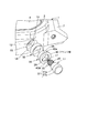
スイッチ装置8は、図2〜図5に示すように、腕時計ケース1の側壁部に設けられた貫通孔10にスライド可能に挿入されて腕時計ケース1の外部に突出する操作部材11を備えている。貫通孔10は、本体ケース2の内部側に形成された小径孔部12と、本体ケース2の外部側に形成された大径孔部13と、外装ケース3に形成された外装孔部14と、を有している。   As shown in FIGS. 2 to 5, the switch device 8 includes an operation member 11 that is slidably inserted into a through hole 10 provided in a side wall portion of the watch case 1 and protrudes outside the watch case 1. . The through hole 10 includes a small diameter hole portion 12 formed on the inner side of the main body case 2, a large diameter hole portion 13 formed on the outer side of the main body case 2, and an outer hole portion 14 formed on the outer case 3. ,have.

この場合、貫通孔10の小径孔部12は、図2および図5に示すように、第1小径孔部12aと第2小径孔部12bとを有している。第1小径孔部12aは、本体ケース2の内部側に形成されている。第2小径孔部12bは、本体ケース2の外部側に形成されている。この第2小径孔部12bは、その内径が第1小径孔部12aの内径よりも大きく、かつ大径孔部13の内径よりも小さく形成されている。この小径孔部12は、その軸方向の長さが本体ケース2の側壁の肉厚のほぼ半分程度の長さに形成されている。   In this case, the small-diameter hole portion 12 of the through hole 10 has a first small-diameter hole portion 12a and a second small-diameter hole portion 12b as shown in FIGS. The first small diameter hole 12 a is formed on the inner side of the main body case 2. The second small diameter hole portion 12 b is formed on the outer side of the main body case 2. The second small diameter hole portion 12 b is formed so that its inner diameter is larger than the inner diameter of the first small diameter hole portion 12 a and smaller than the inner diameter of the large diameter hole portion 13. The small-diameter hole 12 is formed so that its axial length is approximately half the wall thickness of the main body case 2.

また、貫通孔10の大径孔部13は、図2および図5に示すように、小径孔部12の第2小径孔部12bの内径よりも大きく形成されている。この大径孔部13は、その軸方向の長さが小径孔部12の軸方向の長さとほぼ同じか、それよりも少し短く形成されている。これにより、貫通孔10は、小径孔部12の第2小径孔部12bと大径孔部13との境界部に段差部15が設けられた構成になっている。   Moreover, the large diameter hole part 13 of the through-hole 10 is formed larger than the internal diameter of the 2nd small diameter hole part 12b of the small diameter hole part 12, as shown in FIG.2 and FIG.5. The large-diameter hole 13 is formed so that its axial length is substantially the same as or slightly shorter than the axial length of the small-diameter hole 12. Thereby, the through hole 10 has a configuration in which a step portion 15 is provided at a boundary portion between the second small diameter hole portion 12 b and the large diameter hole portion 13 of the small diameter hole portion 12.

さらに、貫通孔10の外装孔部14は、図2および図5に示すように、その内径が大径孔部13の内径よりも少し小さく形成されている。この外装孔部14の周囲における円周方向の両側部に位置する外装ケース3の外面には、後述する操作部材11の頭部18を保護する保護突起部16が、腕時計ケース1の外部に向けて突出して設けられている。   Further, as shown in FIGS. 2 and 5, the exterior hole portion 14 of the through hole 10 is formed so that its inner diameter is slightly smaller than the inner diameter of the large-diameter hole portion 13. On the outer surface of the outer case 3 positioned on both sides in the circumferential direction around the outer hole 14, a protective projection 16 that protects the head 18 of the operation member 11 described later is directed to the outside of the watch case 1. Projecting.

一方、操作部材11は、図2〜図5に示すように、本体ケース2の貫通孔10の小径孔部12にスライド可能に挿入される軸部17と、この軸部17の外端部に設けられて貫通孔10の大径孔部13および外装孔部14の両方の内部に跨った状態でスライド可能に配置される頭部18と、を有している。   On the other hand, as shown in FIGS. 2 to 5, the operation member 11 includes a shaft portion 17 that is slidably inserted into the small-diameter hole portion 12 of the through hole 10 of the main body case 2, and an outer end portion of the shaft portion 17. And a head portion 18 that is slidably arranged in a state straddling both the large-diameter hole portion 13 and the exterior hole portion 14 of the through-hole 10.

軸部17は、図2および図5に示すように、その外径が小径孔部12の第1小径孔部12aの内径とほぼ同じ大きさで、軸方向の長さが小径孔部12と大径孔部13との両方の軸方向の長さよりも少し長く形成されている。これにより、軸部17は、貫通孔10の小径孔部12に挿入された際に、その内端部が本体ケース2の内部に突出し、外端部が大径孔部13の外端部に位置するように構成されている。   As shown in FIGS. 2 and 5, the shaft portion 17 has an outer diameter that is substantially the same as the inner diameter of the first small-diameter hole portion 12 a of the small-diameter hole portion 12, and an axial length that is the same as that of the small-diameter hole portion 12. It is formed a little longer than the axial length of both of the large-diameter holes 13. Thus, when the shaft portion 17 is inserted into the small diameter hole portion 12 of the through hole 10, the inner end portion projects into the body case 2, and the outer end portion corresponds to the outer end portion of the large diameter hole portion 13. Configured to be located.

この場合、本体ケース2の内部に突出した軸部17の内端部には、図2および図5に示すように、Eリングなどの抜止め部材19が取り付けられている。これにより、軸部17は、抜止め部材19が貫通孔10の小径孔部12における第1小径孔部12aの内端部の周囲に位置する本体ケース2の内周面に接離可能に当接することにより、本体ケース2の外部に抜け出さないように構成されている。   In this case, a retaining member 19 such as an E-ring is attached to the inner end portion of the shaft portion 17 protruding into the main body case 2 as shown in FIGS. As a result, the shaft portion 17 can be brought into contact with and separated from the inner peripheral surface of the main body case 2 positioned around the inner end portion of the first small-diameter hole portion 12a in the small-diameter hole portion 12 of the through-hole 10. By being in contact with the main body case 2, the main body case 2 is configured not to come out.

また、この軸部17は、図2および図5に示すように、その内端部が本体ケース2内の時計モジュール6に設けられたスイッチ接点部6aに接離可能に対応するように構成されている。これにより、軸部17は、頭部18の押圧操作に応じて、内端部が本体ケース2内に突出してスイッチ接点部6aを押圧することにより、スイッチ接点部6aをスイッチ動作させるように構成されている。   Further, as shown in FIGS. 2 and 5, the shaft portion 17 is configured such that the inner end thereof corresponds to the switch contact portion 6 a provided in the timepiece module 6 in the main body case 2 so as to be able to contact and separate. ing. Accordingly, the shaft portion 17 is configured to switch the switch contact portion 6a by pressing the switch contact portion 6a by projecting the inner end portion into the body case 2 in response to a pressing operation of the head portion 18. Has been.

さらに、この軸部17は、図2および図5に示すように、その外周面に複数の防水リング20が圧接した状態で摺動するように構成されている。すなわち、複数の防水リング20は、貫通孔10の小径孔部12における第2小径孔部12b内にそれぞれ環状に設けられている。これにより、複数の防水リング20は、軸部17の外周面に摺動可能に圧接し、この状態で軸部17のスライド動作に伴って軸部17の外周面が摺動するように構成されている。   Further, as shown in FIGS. 2 and 5, the shaft portion 17 is configured to slide in a state where a plurality of waterproof rings 20 are in pressure contact with the outer peripheral surface thereof. That is, the plurality of waterproof rings 20 are each provided in an annular shape in the second small diameter hole portion 12 b in the small diameter hole portion 12 of the through hole 10. Thus, the plurality of waterproof rings 20 are slidably pressed against the outer peripheral surface of the shaft portion 17, and in this state, the outer peripheral surface of the shaft portion 17 slides as the shaft portion 17 slides. ing.

また、この軸部17の外端部には、図2〜図4に示すように、頭部18が一体に設けられている。この頭部18は、全体がほぼ円筒状に形成され、貫通孔10の大径孔部13と外装孔部14との両方に跨って配置されるように構成されている。すなわち、この頭部18は、その軸方向の長さが大径孔部13の軸方向の長さと外装孔部14の軸方向の長さとの両方の長さとほぼ同じ長さに形成されている。   Further, as shown in FIGS. 2 to 4, a head portion 18 is integrally provided at the outer end portion of the shaft portion 17. The head portion 18 is formed in a substantially cylindrical shape as a whole, and is configured to be disposed across both the large-diameter hole portion 13 and the exterior hole portion 14 of the through hole 10. That is, the head 18 is formed so that its axial length is substantially the same as both the axial length of the large-diameter hole 13 and the axial length of the exterior hole 14. .

これにより、頭部18は、図2および図5に示すように、軸部17の抜止め部材19が本体ケース2の内周面に当接した際に、大径孔部13内から外装孔部14内に向けて押し出されることにより、頭部18の内端部18aが貫通孔10の段差部15から離れた状態で配置されると共に、頭部18の外端部18bが外装孔部14から腕時計ケース1の外部に向けて押し出されて腕時計ケース1の外部に突出するように構成されている。   As a result, as shown in FIG. 2 and FIG. 5, when the retaining member 19 of the shaft portion 17 comes into contact with the inner peripheral surface of the main body case 2, By being pushed out into the portion 14, the inner end portion 18 a of the head portion 18 is arranged in a state of being separated from the step portion 15 of the through hole 10, and the outer end portion 18 b of the head portion 18 is arranged in the exterior hole portion 14. It is configured to be pushed out from the watch case 1 to protrude outside the watch case 1.

また、この頭部18は、図2および図5に示すように、腕時計ケース1の外部から押し込まれて軸部17の抜止め部材19が本体ケース2の内周面から離れて、軸部17の内端部が時計モジュール6のスイッチ接点部6aを押圧した際に、頭部18の内端部18aが大径孔部13内に押し込まれて段差部15に接近した位置に配置されると共に、頭部18の外端部18bが外装孔部14内に押し込まれた位置に配置されるように構成されている。   As shown in FIGS. 2 and 5, the head 18 is pushed from the outside of the watch case 1 so that the retaining member 19 of the shaft portion 17 is separated from the inner peripheral surface of the body case 2. The inner end 18a of the timepiece module 6 presses the switch contact 6a of the timepiece module 6, and the inner end 18a of the head 18 is pushed into the large-diameter hole 13 so as to be close to the stepped portion 15. The outer end 18b of the head 18 is arranged at a position where it is pushed into the exterior hole 14.

この場合、腕時計ケース1の貫通孔10の大径孔部13内には、図2〜図5に示すように、円筒状のガイド部材21が円筒状の通気フィルタ22を介して装着されている。このガイド部材21は、その内径が頭部18の外径よりも少し大きく、かつ外装孔部14の内径よりも少し小さく形成されている。また、このガイド部材21は、その外径が外装孔部14の内径よりも少し大きく、かつ大径孔部13の内径よりも小さく形成されている。さらに、このガイド部材21は、その軸方向の長さが大径孔部13の軸方向の長さとほぼ同じ長さに形成されている。   In this case, a cylindrical guide member 21 is mounted in the large-diameter hole 13 of the through hole 10 of the watch case 1 via a cylindrical ventilation filter 22 as shown in FIGS. . The guide member 21 is formed so that its inner diameter is slightly larger than the outer diameter of the head 18 and slightly smaller than the inner diameter of the exterior hole portion 14. Further, the guide member 21 has an outer diameter that is slightly larger than the inner diameter of the exterior hole portion 14 and smaller than the inner diameter of the large-diameter hole portion 13. Further, the guide member 21 has an axial length that is substantially the same as the axial length of the large-diameter hole 13.

また、このガイド部材21は、図2および図5に示すように、位置規制部によって貫通孔10の大径孔部13内に位置規制されるように構成されている。この位置規制部は、貫通孔10の小径孔部12と大径孔部13との境界部に位置してガイド部材21の内端部が当接する段差部15と、貫通孔10の大径孔部13の外端部に位置してガイド部材21の外端部が当接する腕時計ケース1の外装ケース3と、を備えている。   Further, as shown in FIGS. 2 and 5, the guide member 21 is configured such that the position of the guide member 21 is regulated within the large-diameter hole 13 of the through hole 10 by the position regulating unit. The position restricting portion is located at a boundary portion between the small diameter hole portion 12 and the large diameter hole portion 13 of the through hole 10 and the stepped portion 15 with which the inner end portion of the guide member 21 abuts, and the large diameter hole of the through hole 10. And an outer case 3 of the watch case 1 that is located at the outer end of the portion 13 and abuts against the outer end of the guide member 21.

すなわち、この位置規制部は、図2および図5に示すように、ガイド部材21が大径孔部13内に通気フィルタ22と共に嵌め込まれた際に、ガイド部材21の内端部が貫通孔10の段差部15に当接し、ガイド部材21の外端部が外装ケース3の外装孔部14の内側縁部に当接することにより、ガイド部材21を大径孔部13内に位置規制するように構成されている。   That is, as shown in FIGS. 2 and 5, when the guide member 21 is fitted into the large-diameter hole portion 13 together with the ventilation filter 22, the position restricting portion has the inner end portion of the guide member 21 formed in the through hole 10. So that the outer end of the guide member 21 contacts the inner edge of the exterior hole 14 of the exterior case 3 so that the position of the guide member 21 is regulated within the large-diameter hole 13. It is configured.

この場合、頭部18は、図2〜図5に示すように、その外周面に防水部材24が設けられ、この防水部材24がガイド部材21の内周面に圧接した状態で摺動するように構成されている。すなわち、この防水部材24は、リング状に形成され、頭部18の外周面から突出した状態で環状に設けられている。これにより、防水部材24は、ガイド部材21の内周面に摺動可能に圧接し、この状態で頭部18のスライド動作に伴ってガイド部材21の内周面に沿って摺動するように構成されている。   In this case, as shown in FIGS. 2 to 5, the head 18 is provided with a waterproof member 24 on its outer peripheral surface, and the waterproof member 24 slides in a state of being pressed against the inner peripheral surface of the guide member 21. It is configured. That is, the waterproof member 24 is formed in a ring shape and is provided in an annular shape in a state of protruding from the outer peripheral surface of the head 18. As a result, the waterproof member 24 is slidably pressed against the inner peripheral surface of the guide member 21, and in this state, the waterproof member 24 slides along the inner peripheral surface of the guide member 21 as the head 18 slides. It is configured.

また、この頭部18の内端部18a側には、図2〜図5に示すように、コイルばね25が軸部17の外周に沿って配置されている。すなわち、このコイルばね25は、その一端部が貫通孔10の小径孔部12内に位置する防水リング20の外端部に配置されたワッシャ26に弾接し、他端部が頭部18の内端部18aの内部に挿入されて弾接し、この状態で頭部18を腕時計ケース1の外部に向けて押し出す方向に付勢するように構成されている。   Further, as shown in FIGS. 2 to 5, a coil spring 25 is disposed along the outer periphery of the shaft portion 17 on the inner end portion 18 a side of the head portion 18. That is, one end of the coil spring 25 is elastically contacted with a washer 26 disposed at the outer end of the waterproof ring 20 located in the small diameter hole 12 of the through hole 10, and the other end is within the head 18. The head 18 is inserted into and elastically contacted with the end portion 18a, and in this state, the head 18 is configured to be urged in the direction of pushing out toward the outside of the watch case 1.

ところで、このスイッチ装置8は、図2および図5に示すように、ガイド部材21内の空気と腕時計ケース1の外部の空気とを通気させる通気路27を備えている。すなわち、この通気路27は、ガイド部材21に設けられた通気部28と、ガイド部材21の外周面と本体ケース2の大径孔部13の内周面との間に配置された通気フィルタ22と、を備えている。   By the way, as shown in FIGS. 2 and 5, the switch device 8 includes an air passage 27 that allows the air in the guide member 21 and the air outside the watch case 1 to vent. In other words, the ventilation path 27 includes a ventilation portion 28 provided in the guide member 21, and a ventilation filter 22 disposed between the outer peripheral surface of the guide member 21 and the inner peripheral surface of the large-diameter hole portion 13 of the main body case 2. And.

通気部28は、図2〜図5に示すように、操作部材11の頭部18がガイド部材21内に押し込まれた際に、頭部18の内端部よりも腕時計ケース1の内部側に位置するガイド部材21の箇所に設けられている。すなわち、この通気部28は、本体ケース2の貫通孔10における小径孔部12と大径孔部13との境界部に位置する段差部15に当接するガイド部材21の内端部に設けられた複数の通気溝である。この通気部28は、ガイド部材21の内端部における6箇所に設けられ、ガイド部材21の内部と外部とを通気するように構成されている。   2 to 5, when the head 18 of the operation member 11 is pushed into the guide member 21, the ventilation portion 28 is located closer to the inner side of the watch case 1 than the inner end of the head 18. It is provided in the location of the guide member 21 located. That is, the ventilation portion 28 is provided at the inner end portion of the guide member 21 that contacts the step portion 15 located at the boundary portion between the small diameter hole portion 12 and the large diameter hole portion 13 in the through hole 10 of the main body case 2. A plurality of ventilation grooves. The ventilation portions 28 are provided at six locations on the inner end portion of the guide member 21 and are configured to ventilate the inside and outside of the guide member 21.

通気フィルタ22は、空気などの気体や水などの液体を通過させ、泥や埃などを通過させない不織布や多孔質材などの材料からなり、図2〜図5に示すように、全体がほぼ円筒状に形成されている。この通気フィルタ22は、その内径がガイド部材21の外径とほぼ同じで、外径が大径孔部13の内径とほぼ同じ大きさに形成されている。   The ventilation filter 22 is made of a material such as a non-woven fabric or a porous material that allows a gas such as air or a liquid such as water to pass therethrough and does not allow mud or dust to pass through. As shown in FIGS. It is formed in a shape. The ventilation filter 22 has an inner diameter that is substantially the same as the outer diameter of the guide member 21, and an outer diameter that is substantially the same as the inner diameter of the large-diameter hole 13.

また、この通気フィルタ22は、図2〜図5に示すように、その軸方向の長さがガイド部材21の軸方向の長さ、または大径孔部13の軸方向の長さと同じ長さで形成されている。これにより、通気フィルタ22は、ガイド部材21の外周面に装着され、この状態でガイド部材21と共に大径孔部13内に挿入されることにより、ガイド部材21と大径孔部13との間に嵌め込まれるように構成されている。   As shown in FIGS. 2 to 5, the ventilation filter 22 has an axial length equal to the axial length of the guide member 21 or the axial length of the large-diameter hole 13. It is formed with. As a result, the ventilation filter 22 is mounted on the outer peripheral surface of the guide member 21, and is inserted into the large-diameter hole 13 together with the guide member 21 in this state, so that the gap between the guide member 21 and the large-diameter hole 13 is reached. It is comprised so that it may be inserted in.

この場合、腕時計ケース1の外部側に位置するガイド部材21の外周部には、図2〜図5に示すように、複数の係止突起部21aが円周方向に沿って所定間隔で設けられている。これら複数の係止突起部21aは、その各外周面が大径孔部13の内周面にそれぞれ圧接するように構成されている。これに伴って、腕時計ケース1の外部側に位置する通気フィルタ22には、ガイド部材21の複数の係止突起部21aがそれぞれ係合して外周側に露出する複数の係合溝22aが通気フィルタ22の中間部から外端部に亘って設けられている。   In this case, as shown in FIGS. 2 to 5, a plurality of locking projections 21 a are provided at predetermined intervals along the circumferential direction on the outer peripheral portion of the guide member 21 located on the outer side of the watch case 1. ing. The plurality of locking projections 21 a are configured such that their outer peripheral surfaces are in pressure contact with the inner peripheral surface of the large-diameter hole portion 13, respectively. Accordingly, a plurality of engaging grooves 22a that are exposed to the outer peripheral side through the engagement of the plurality of engaging projections 21a of the guide member 21 are vented to the ventilation filter 22 that is located outside the wristwatch case 1. The filter 22 is provided from the middle part to the outer end part.

このため、ガイド部材21は、図2〜図5に示すように、その複数の係止突起部21aが通気フィルタ22の複数の係合溝22aに嵌合した状態で、ガイド部材21の外周面に通気フィルタ22が装着されることにより、通気フィルタ22の円周方向への回転を規制するように構成されている。   Therefore, as shown in FIGS. 2 to 5, the guide member 21 has an outer peripheral surface of the guide member 21 in a state in which the plurality of locking projections 21 a are fitted in the plurality of engagement grooves 22 a of the ventilation filter 22. When the ventilation filter 22 is attached to the air filter 22, the rotation of the ventilation filter 22 in the circumferential direction is restricted.

また、このガイド部材21は、図2〜図5に示すように、その外周面に通気フィルタ22が装着された状態で、大径孔部13の内部に装着された際に、ガイド部材21の複数の係止突起部21aが大径孔部13の内周面にそれぞれ圧接されることにより、大径孔部13に対するガイド部材21の円周方向への回転が規制されるように構成されている。   As shown in FIGS. 2 to 5, when the guide member 21 is mounted inside the large-diameter hole 13 with the ventilation filter 22 mounted on the outer peripheral surface thereof, The plurality of locking protrusions 21a are pressed against the inner peripheral surface of the large-diameter hole 13, respectively, so that the rotation of the guide member 21 in the circumferential direction with respect to the large-diameter hole 13 is restricted. Yes.

これにより、通気路27は、図2および図5に示すように、操作部材11の頭部18が本体ケース2内に向けて押し込まれる際に、ガイド部材21内の空気が、ガイド部材21の内端部に設けられた通気部28を通して通気フィルタ22に送り込まれ、この送り込まれた空気が、通気フィルタ22を通して、ガイド部材21の外端部と外装ケース3の内周面との間から外装孔部14内に送り込まれ、この外装孔部14内に送り込まれた空気が外装孔部14の内周面と頭部18の外周面との間を通して腕時計ケース1の外部に排出されるように構成されている。   Thereby, as shown in FIGS. 2 and 5, when the head 18 of the operation member 11 is pushed into the main body case 2, the air in the guide member 21 causes the air in the guide member 21 to be The air is sent to the ventilation filter 22 through the ventilation portion 28 provided at the inner end portion, and the supplied air passes through the ventilation filter 22 from between the outer end portion of the guide member 21 and the inner peripheral surface of the outer case 3. The air sent into the hole 14 is exhausted to the outside of the watch case 1 through the space between the inner peripheral surface of the outer hole 14 and the outer peripheral surface of the head 18. It is configured.

また、この通気路27は、図2および図5に示すように、操作部材11の頭部18がコイルばね25のばね力によって本体ケース2の外部に向けて押し出される際に、腕時計ケース1の外部の空気が、外装孔部14の内周面と頭部18の外周面との間を通してガイド部材21の外端部と外装ケース3の内周面との間に送り込まれ、この送り込まれた空気が通気フィルタ22を通してガイド部材21の内端部に設けられた通気部28からガイド部材21内に送り込まれるように構成されている。   As shown in FIGS. 2 and 5, the air passage 27 is provided on the wristwatch case 1 when the head 18 of the operation member 11 is pushed out of the main body case 2 by the spring force of the coil spring 25. External air is sent between the outer peripheral surface of the guide member 21 and the inner peripheral surface of the outer case 3 through the space between the inner peripheral surface of the outer hole portion 14 and the outer peripheral surface of the head portion 18. Air is configured to be fed into the guide member 21 from a ventilation portion 28 provided at an inner end portion of the guide member 21 through the ventilation filter 22.

次に、このような腕時計におけるスイッチ装置8の作用について説明する。
このスイッチ装置8は、通常の状態で、ガイド部材21内に位置する操作部材11の軸部17の外周に沿って配置されたコイルばね25のばね力によって、頭部18が腕時計ケース1の外部に向けて押し出されている。
Next, the operation of the switch device 8 in such a wristwatch will be described.
In the normal state, the switch device 8 is configured such that the head 18 is outside the watch case 1 by the spring force of the coil spring 25 disposed along the outer periphery of the shaft portion 17 of the operation member 11 located in the guide member 21. It is pushed out towards

この状態では、本体ケース2の内部に突出している操作部材11の軸部17における内端部に設けられた抜止め部材19が、貫通孔10の第1小径孔部12aにおける内端部の周囲に位置する本体ケース2の内周面に当接する。また、この状態では、操作部材11の頭部18の内端部18aが貫通孔10の段差部15から腕時計ケース1の外部側に離れて、頭部18の外端部18bが第2筒部18から腕時計ケース1の外部に突出している。   In this state, the retaining member 19 provided at the inner end portion of the shaft portion 17 of the operation member 11 protruding inside the main body case 2 is around the inner end portion of the first small diameter hole portion 12a of the through hole 10. It abuts on the inner peripheral surface of the main body case 2 located at the position. In this state, the inner end 18a of the head 18 of the operation member 11 is separated from the stepped portion 15 of the through hole 10 to the outside of the watch case 1, and the outer end 18b of the head 18 is the second cylindrical portion. 18 protrudes from the wristwatch case 1 to the outside.

これにより、操作部材11の軸部17の内端部が、時計モジュール6に設けられたスイッチ接点部6aから離れ、このスイッチ接点部6aがオフ状態になっている。この状態で、操作部材11の頭部18をコイルばね25のばね力に抗して押圧操作すると、操作部材11の頭部18がガイド部材21内に押し込まれると共に、軸部17が貫通孔10の小径孔部12内を本体ケース2の内部に向けてスライドする。   As a result, the inner end portion of the shaft portion 17 of the operation member 11 is separated from the switch contact portion 6a provided in the timepiece module 6, and the switch contact portion 6a is in an OFF state. When the head 18 of the operation member 11 is pressed against the spring force of the coil spring 25 in this state, the head 18 of the operation member 11 is pushed into the guide member 21 and the shaft portion 17 is inserted into the through hole 10. The small-diameter hole 12 is slid toward the inside of the main body case 2.

このときには、軸部17の外周面が貫通孔10の第2小径孔部12b内に設けられた複数の防水リング20に圧接した状態で摺動する。同様に、頭部18の外周面に設けられた防水部材24がガイド部材21の内周面に圧接した状態で摺動する。このため、防水部材24によって頭部18の外周面とガイド部材21の内周面との間からガイド部材21内に、腕時計ケース1の外部の水や泥などの異物が浸入することがなく、ガイド部材21内の防水性および気密性が図られる。   At this time, the outer peripheral surface of the shaft portion 17 slides in a state of being pressed against the plurality of waterproof rings 20 provided in the second small diameter hole portion 12 b of the through hole 10. Similarly, the waterproof member 24 provided on the outer peripheral surface of the head 18 slides in a state of being pressed against the inner peripheral surface of the guide member 21. Therefore, foreign matter such as water and mud outside the watch case 1 does not enter the guide member 21 from between the outer peripheral surface of the head 18 and the inner peripheral surface of the guide member 21 by the waterproof member 24. Waterproofness and airtightness in the guide member 21 are achieved.

また、このときには、貫通孔10内におけるガイド部材21と操作部材11の頭部18と小径孔部12内の複数の防水リング20とで囲われた領域であるガイド部材21内の空気が、本体ケース2の内部に向けてスライドする頭部18のスライドに応じて、徐々に圧縮されて、空気圧が高くなる。この圧縮された空気は、通気路27を通して腕時計ケース1の外部に排出される。   At this time, the air in the guide member 21, which is a region surrounded by the guide member 21 in the through hole 10, the head 18 of the operation member 11, and the plurality of waterproof rings 20 in the small-diameter hole 12, As the head 18 slides toward the inside of the case 2, the head 18 is gradually compressed to increase the air pressure. The compressed air is discharged to the outside of the watch case 1 through the air passage 27.

すなわち、圧縮された空気は、ガイド部材21の内端部に設けられた複数の通気溝である通気部28からガイド部材21の外周面と大径孔部13の内周面との間に配置された通気フィルタ22に送り込まれる。この送り込まれた空気は、通気フィルタ22を通してガイド部材21の外端部と外装ケース3の内面との間から外装孔部14内に送り込まれる。   That is, the compressed air is disposed between the outer peripheral surface of the guide member 21 and the inner peripheral surface of the large-diameter hole portion 13 from the ventilation portion 28 which is a plurality of ventilation grooves provided at the inner end portion of the guide member 21. Sent to the vent filter 22. The sent air is sent into the exterior hole portion 14 from between the outer end portion of the guide member 21 and the inner surface of the exterior case 3 through the ventilation filter 22.

この外装孔部14内に送り込まれた空気は、外装孔部14の内周面と頭部18の外周面との間から腕時計ケース1の外部に排出される。このため、貫通孔10内におけるガイド部材21と操作部材11の頭部18と小径孔部12内の複数の防水リング20とで囲われた領域であるガイド部材21内の空気圧は、頭部18がスライド動作しても、腕時計ケース1の外部の気圧とほぼ同じに保たれる。   The air sent into the exterior hole 14 is discharged to the outside of the watch case 1 from between the inner peripheral surface of the exterior hole 14 and the outer peripheral surface of the head 18. For this reason, the air pressure in the guide member 21, which is an area surrounded by the guide member 21 in the through hole 10, the head 18 of the operation member 11, and the plurality of waterproof rings 20 in the small diameter hole 12, Even if the slide operation, the atmospheric pressure outside the watch case 1 is kept substantially the same.

これにより、操作部材11の頭部18を押圧操作した際に、貫通孔10内におけるガイド部材21と操作部材11の頭部18と小径孔部12内の複数の防水リング20とで囲われた領域であるガイド部材21内の空気が圧縮されても、操作部材11を円滑にかつ良好にスライドさせることができる。このときには、操作部材11のスライドに伴って軸部17の内端部が本体ケース2内に押し込まれ、この軸部17の内端部によって時計モジュール6のスイッチ接点部6aが押されてオン動作する。   Thereby, when the head 18 of the operation member 11 is pressed, the guide member 21 in the through hole 10, the head 18 of the operation member 11, and the plurality of waterproof rings 20 in the small diameter hole 12 are surrounded. Even if the air in the guide member 21 that is the region is compressed, the operation member 11 can be smoothly and satisfactorily slid. At this time, the inner end portion of the shaft portion 17 is pushed into the main body case 2 as the operating member 11 slides, and the switch contact portion 6a of the timepiece module 6 is pushed by the inner end portion of the shaft portion 17 to turn on. To do.

一方、スイッチ接点部6aが押されてオン動作した後は、ガイド部材21内に位置する操作部材11の軸部17の外周に沿って配置されたコイルばね25のばね力によって、頭部18が腕時計ケース1の外部に向けて押し出される。このときには、操作部材11の軸部17が、貫通孔10の小径孔部12内を腕時計ケース1の外部に向けてスライドする。このときにも、軸部17の外周面が小径孔部12の第2小径孔部12bに設けられた複数の防水リング20に圧接した状態で摺動する。   On the other hand, after the switch contact portion 6 a is pressed and turned on, the head 18 is moved by the spring force of the coil spring 25 arranged along the outer periphery of the shaft portion 17 of the operation member 11 located in the guide member 21. Pushed toward the outside of the watch case 1. At this time, the shaft portion 17 of the operation member 11 slides inside the small diameter hole portion 12 of the through hole 10 toward the outside of the watch case 1. Also at this time, the outer peripheral surface of the shaft portion 17 slides in a state of being pressed against the plurality of waterproof rings 20 provided in the second small diameter hole portion 12b of the small diameter hole portion 12.

また、このときにも、操作部材11の頭部18の外周面に設けられた防水部材24がガイド部材21の内周面に圧接した状態で摺動する。このため、防水部材24によって頭部18の外周面とガイド部材21の内周面との間からガイド部材21内に、腕時計ケース1の外部の水や泥などの異物が浸入することがなく、ガイド部材21内の防水性および気密性が図られる。   Also at this time, the waterproof member 24 provided on the outer peripheral surface of the head 18 of the operation member 11 slides in a state of being pressed against the inner peripheral surface of the guide member 21. Therefore, foreign matter such as water and mud outside the watch case 1 does not enter the guide member 21 from between the outer peripheral surface of the head 18 and the inner peripheral surface of the guide member 21 by the waterproof member 24. Waterproofness and airtightness in the guide member 21 are achieved.

このときには、貫通孔10内におけるガイド部材21と操作部材11の頭部18と小径孔部12内の複数の防水リング20とで囲われた領域であるガイド部材21内の空気が、腕時計ケース1の外部に向けてスライドする頭部18のスライドに応じて、徐々に膨張して、空気圧が下がる。このように空気圧が徐々に下がる際には、腕時計ケース1の外部の空気が通気路27を通してガイド部材21内に送り込まれる。   At this time, the air in the guide member 21, which is a region surrounded by the guide member 21 in the through hole 10, the head 18 of the operation member 11, and the plurality of waterproof rings 20 in the small diameter hole portion 12, is watch case 1. As the head 18 slides toward the outside, the air gradually expands and the air pressure decreases. Thus, when the air pressure gradually decreases, the air outside the watch case 1 is sent into the guide member 21 through the air passage 27.

すなわち、腕時計ケース1の外部の空気は、外装孔部14の内周面と頭部18の外周面との間からガイド部材21の外端部と外装ケース3の内面との間に取り込まれ、この取り込まれた空気は、通気フィルタ22に送り込まれる。この通気フィルタ22に送り込まれた空気は、通気フィルタ22を通してガイド部材21の内端部に設けられた複数の通気溝である通気部28からガイド部材21内に送り込まれる。   That is, the air outside the watch case 1 is taken in between the outer end of the guide member 21 and the inner surface of the outer case 3 from between the inner peripheral surface of the outer hole 14 and the outer peripheral surface of the head 18. This taken-in air is sent to the ventilation filter 22. The air sent into the ventilation filter 22 is sent into the guide member 21 through the ventilation filter 22 from the ventilation portion 28 which is a plurality of ventilation grooves provided at the inner end portion of the guide member 21.

これにより、貫通孔10内におけるガイド部材21と操作部材11の頭部18と小径孔部12内の複数の防水リング20とで囲われた領域であるガイド部材21内の空気圧は、腕時計ケース1の外部の空気が頭部18がスライド動作に伴ってガイド部材21内に取り込まれることにより、頭部18がスライド動作しても、腕時計ケース1の外部の気圧とほぼ同じに保たれる。   As a result, the air pressure in the guide member 21, which is an area surrounded by the guide member 21 in the through hole 10, the head 18 of the operation member 11, and the plurality of waterproof rings 20 in the small-diameter hole portion 12, is When the head 18 is taken into the guide member 21 as the head 18 slides, the air pressure outside the wristwatch case 1 is kept substantially the same even when the head 18 slides.

このため、コイルばね25のばね力によって操作部材11が元の位置に戻る際には、貫通孔10内におけるガイド部材21と操作部材11の頭部18と小径孔部12内の複数の防水リング20とで囲われた領域であるガイド部材21内の空気が膨張して空気圧が下っても、操作部材11を円滑にかつ良好にスライドさせることができる。このときには、操作部材11のスライドに伴って軸部17の内端部が時計モジュール6のスイッチ接点部6aから離れ、スイッチ接点部6aがオフ状態になる。   For this reason, when the operating member 11 returns to the original position by the spring force of the coil spring 25, the guide member 21 in the through hole 10, the head 18 of the operating member 11, and the plurality of waterproof rings in the small diameter hole portion 12. The operating member 11 can be smoothly and satisfactorily slid even when the air in the guide member 21, which is an area surrounded by the reference numeral 20, expands and the air pressure decreases. At this time, as the operating member 11 slides, the inner end portion of the shaft portion 17 moves away from the switch contact portion 6a of the timepiece module 6, and the switch contact portion 6a is turned off.

このように、この腕時計のスイッチ装置8によれば、小径孔部12と大径孔部13とを有する貫通孔10が設けられた腕時計ケース1と、大径孔部13に配置された筒状のガイド部材21と、小径孔部12内にスライド可能に挿入する軸部17およびガイド部材21内にスライド可能に配置される頭部18を有する操作部材11と、頭部18の外周面とガイド部材21の内周面との間に設けられた防水部材24と、ガイド部材21の通気部28およびガイド部材21と大径孔部13との間の通気フィルタ22を通して、ガイド部材21内の空気と腕時計ケース1の外部の空気とを通気させる通気路27と、を備えているので、防水性を確保し、かつ操作性の向上を図ることができる。   Thus, according to this wristwatch switch device 8, the wristwatch case 1 provided with the through hole 10 having the small diameter hole portion 12 and the large diameter hole portion 13, and the cylindrical shape disposed in the large diameter hole portion 13. The guide member 21, the shaft portion 17 slidably inserted into the small-diameter hole portion 12, the operation member 11 having the head 18 slidably disposed in the guide member 21, the outer peripheral surface of the head 18 and the guide The air in the guide member 21 passes through the waterproof member 24 provided between the inner peripheral surface of the member 21, the ventilation portion 28 of the guide member 21 and the ventilation filter 22 between the guide member 21 and the large-diameter hole portion 13. And the air passage 27 for allowing the air outside the watch case 1 to ventilate, it is possible to ensure waterproofness and improve operability.

すなわち、この腕時計のスイッチ装置8では、防水部材24によってガイド部材21の内周面と操作部材11の頭部18の外周面との間の防水性および気密性を確保することができる共に、通気部28と通気フィルタ22とで構成された通気路27によって、ガイド部材21内の空気と腕時計ケース1の外部の空気とを通気させることができるので、ガイド部材21内の空気圧を腕時計ケース1の外部の気圧とほぼ同じに保つことができる。このため、防水部材24によって防水性および気密性を確保しても、操作部材11の操作性を向上させることができる。   That is, in the wristwatch switch device 8, the waterproof member 24 can ensure waterproofness and airtightness between the inner peripheral surface of the guide member 21 and the outer peripheral surface of the head portion 18 of the operation member 11, and also allows ventilation. The air passage 27 formed by the portion 28 and the ventilation filter 22 can ventilate the air in the guide member 21 and the air outside the watch case 1, so that the air pressure in the guide member 21 is changed to the air pressure in the watch case 1. It can be kept almost the same as the external atmospheric pressure. For this reason, even if waterproofness and airtightness are ensured by the waterproof member 24, the operability of the operation member 11 can be improved.

また、このスイッチ装置8では、ガイド部材21内に仮に水などの液体が浸入しても、その浸入した水などの液体を通気フィルタ22の毛細管現象によって腕時計ケース1の外部に排出することができる。このため、ガイド部材21内に水などの液体が溜まることがないので、防錆効果があるほか、操作部材11の操作性を、より一層、確保することができ、これにより操作部材11を良好にかつ円滑に操作させることができる。   Further, in this switch device 8, even if a liquid such as water enters the guide member 21, the liquid such as water that has entered can be discharged to the outside of the watch case 1 by the capillary phenomenon of the ventilation filter 22. . For this reason, since liquids, such as water, do not accumulate in the guide member 21, in addition to having a rust prevention effect, the operability of the operation member 11 can be further ensured, thereby making the operation member 11 better. And can be operated smoothly.

この場合、通気部28は、操作部材11の頭部18がガイド部材21内に押し込まれた際に、頭部18の内端部18aよりも腕時計ケース1の内部側に位置するガイド部材21の箇所、つまりガイド部材21の内端部に設けられていることにより、操作部材11の頭部18がガイド部材21内をスライドしても、頭部18によって通気部28が塞がれることがない。このため、操作部材11の頭部18のスライド動作に応じて、ガイド部材21内の空気と腕時計ケース1の外部の空気とを確実にかつ良好に通気することができる。   In this case, when the head 18 of the operation member 11 is pushed into the guide member 21, the ventilation portion 28 is provided on the guide member 21 located on the inner side of the wristwatch case 1 with respect to the inner end 18 a of the head 18. By being provided at the location, that is, the inner end portion of the guide member 21, even if the head portion 18 of the operation member 11 slides inside the guide member 21, the ventilation portion 28 is not blocked by the head portion 18. . For this reason, the air in the guide member 21 and the air outside the watch case 1 can be surely and satisfactorily ventilated according to the sliding movement of the head 18 of the operation member 11.

また、このスイッチ装置8では、防水部材24が操作部材11の頭部18の外周に設けられ、この状態で貫通孔10の大径孔部13内に配置されたガイド部材21の内周面に圧接した状態で摺動することにより、操作部材11のスライド動作に応じて防水部材24がガイド部材21の内周面に沿って移動しても、ガイド部材21の内周面と操作部材11の頭部18の外周面との間の防水性および気密性を確保することができる。   Further, in the switch device 8, the waterproof member 24 is provided on the outer periphery of the head 18 of the operation member 11, and in this state, on the inner peripheral surface of the guide member 21 disposed in the large-diameter hole portion 13 of the through hole 10. By sliding in the pressed state, even if the waterproof member 24 moves along the inner peripheral surface of the guide member 21 in accordance with the sliding operation of the operation member 11, the inner peripheral surface of the guide member 21 and the operation member 11 Waterproofness and airtightness with the outer peripheral surface of the head 18 can be ensured.

また、このスイッチ装置8では、腕時計ケース1の外部側に位置するガイド部材21の外周部に、複数の係止突起部21aが円周方向に沿って設けられており、円筒状の通気フィルタ22に、ガイド部材21の複数の係止突起部21aが係合する複数の係合溝22aが設けられていることにより、ガイド部材21の複数の係止突起部21aを通気フィルタ22の複数の係合溝22aに嵌合させることができるので、ガイド部材21の外周面に通気フィルタ22を装着した際に、ガイド部材21に対する通気フィルタ22の円周方向への回転を確実にかつ良好に規制することができる。   Further, in the switch device 8, a plurality of locking projections 21 a are provided along the circumferential direction on the outer peripheral portion of the guide member 21 located on the outside of the watch case 1, and the cylindrical ventilation filter 22 is provided. In addition, a plurality of engaging grooves 22 a that engage with the plurality of locking projections 21 a of the guide member 21 are provided, so that the plurality of locking projections 21 a of the guide member 21 are connected to the plurality of engagements of the ventilation filter 22. Since the fitting groove 22a can be fitted, when the ventilation filter 22 is mounted on the outer peripheral surface of the guide member 21, the rotation of the ventilation filter 22 in the circumferential direction with respect to the guide member 21 is reliably and well regulated. be able to.

この場合、複数の係止突起部21aは、その各外周面が大径孔部13の内周面にそれぞれ圧接するように構成されていることにより、ガイド部材21の外周面に通気フィルタ22が装着された状態で、ガイド部材21を貫通孔10の大径孔部13の内部に装着した際に、ガイド部材21の複数の係止突起部21aを大径孔部13の内周面にそれぞれ圧接させることができるので、大径孔部13内に対するガイド部材21の円周方向への回転を確実にかつ良好に規制することができ、これにより操作部材11の頭部18が回転した際に、その頭部18の回転と共にガイド部材21が回転しないようにすることができる。   In this case, the plurality of locking projections 21 a are configured such that their outer peripheral surfaces are in pressure contact with the inner peripheral surface of the large-diameter hole 13, respectively, so that the ventilation filter 22 is provided on the outer peripheral surface of the guide member 21. When the guide member 21 is mounted inside the large-diameter hole portion 13 of the through hole 10 in the mounted state, the plurality of locking projections 21a of the guide member 21 are respectively formed on the inner peripheral surface of the large-diameter hole portion 13. Since it can be press-contacted, the rotation of the guide member 21 in the circumferential direction with respect to the inside of the large-diameter hole portion 13 can be reliably and satisfactorily restricted, so that when the head 18 of the operation member 11 is rotated. The guide member 21 can be prevented from rotating with the rotation of the head portion 18.

さらに、このスイッチ装置8では、貫通孔10の大径孔部13に対するガイド部材21の位置を規制する位置規制部を備えていることにより、ガイド部材21内を操作部材11の頭部18がスライドする際に、位置規制部によってガイド部材21が頭部18と共に軸方向に移動するのを確実にかつ良好に防ぐことができる。   Further, the switch device 8 includes a position restricting portion that restricts the position of the guide member 21 with respect to the large-diameter hole portion 13 of the through hole 10, so that the head 18 of the operation member 11 slides inside the guide member 21. In doing so, it is possible to reliably and satisfactorily prevent the guide member 21 from moving in the axial direction together with the head 18 by the position restricting portion.

すなわち、この位置規制部は、貫通孔10の小径孔部12と大径孔部13との境界部に位置してガイド部材21の内端部が当接する段差部15と、貫通孔10の大径孔部13の外端部に位置してガイド部材21の外端部が当接する腕時計ケース1の外装ケース3と、を備えていることにより、貫通孔10の段差部15にガイド部材21の内端部を当接させることができると共に、腕時計ケース1の外装ケース3の内面にガイド部材21の外端部を当接させることができるので、ガイド部材21が頭部18と共に軸方向に移動するのを確実にかつ良好に防ぐことができる。   That is, the position restricting portion is located at the boundary portion between the small-diameter hole portion 12 and the large-diameter hole portion 13 of the through-hole 10 and the step portion 15 with which the inner end portion of the guide member 21 abuts, and the large through-hole 10. And the exterior case 3 of the watch case 1 that is located at the outer end portion of the radial hole portion 13 and is in contact with the outer end portion of the guide member 21, so that the step portion 15 of the through hole 10 has the guide member 21. Since the inner end can be brought into contact with the inner end of the exterior case 3 of the wristwatch case 1 and the outer end of the guide member 21 can be brought into contact with the head 18, the guide member 21 moves in the axial direction together with the head 18. Can be reliably and well prevented.

なお、上述した第1実施形態では、操作部材11の頭部18の外周部に防水部材24を設け、この防水部材24をガイド部材21の内周面に摺動可能に圧接させた場合について述べたが、これに限らず、例えばガイド部材21の内周面に防水部材24を設け、この防水部材24を操作部材11の頭部18の外周面に摺動可能に圧接させた構成であっても良い。   In the first embodiment described above, a case where the waterproof member 24 is provided on the outer peripheral portion of the head 18 of the operation member 11 and the waterproof member 24 is slidably pressed on the inner peripheral surface of the guide member 21 is described. However, the present invention is not limited to this. For example, a waterproof member 24 is provided on the inner peripheral surface of the guide member 21, and the waterproof member 24 is slidably pressed against the outer peripheral surface of the head 18 of the operation member 11. Also good.

(第2実施形態)
次に、図6〜図10を参照して、この発明を腕時計に適用した第2実施形態について説明する。なお、図1〜図5に示された第1実施形態と同一部分には同一符号を付して説明する。
この腕時計のスイッチ装置34は、図6〜図10に示すように、ガイド部材35と通気フィルタ36とが第1実施形態と異なる構成であり、これ以外は第1実施形態とほぼ同じ構成になっている。
(Second Embodiment)
Next, a second embodiment in which the present invention is applied to a wristwatch will be described with reference to FIGS. In addition, the same code | symbol is attached | subjected and demonstrated to the same part as 1st Embodiment shown by FIGS.
As shown in FIGS. 6 to 10, the wristwatch switch device 34 has a guide member 35 and a ventilation filter 36 that are different from those of the first embodiment, and other than this, the configuration is substantially the same as that of the first embodiment. ing.

この場合、操作部材11の頭部37は、図6〜図9に示すように、腕時計ケース1の内部側が小径部37aに形成され、腕時計ケース1の外部側が大径部37bに形成されている。この頭部37の大径部37bは、その外径が小径部37aの外径よりも大きく、かつ貫通孔10の外装孔部14の内径よりも少し小さく形成されている。   In this case, as shown in FIGS. 6 to 9, the head 37 of the operation member 11 is formed with a small diameter portion 37 a on the inner side of the watch case 1 and formed with a large diameter portion 37 b on the outer side of the watch case 1. . The large diameter portion 37 b of the head portion 37 is formed so that the outer diameter is larger than the outer diameter of the small diameter portion 37 a and slightly smaller than the inner diameter of the exterior hole portion 14 of the through hole 10.

また、この大径部37bは、図6および図9に示すように、その軸方向の長さが外装孔部14の軸方向の長さとほぼ同じ長さで形成されている。これにより、頭部37は、小径部37aが貫通孔10の大径孔部13と外装ケース3の外装孔部14との両方に跨って配置され、大径部37bが外装孔部14内に出没可能に配置されるように構成されている。   Further, as shown in FIGS. 6 and 9, the large-diameter portion 37 b has an axial length that is substantially the same as the axial length of the exterior hole portion 14. As a result, the head 37 has the small-diameter portion 37 a disposed over both the large-diameter hole portion 13 of the through hole 10 and the exterior hole portion 14 of the exterior case 3, and the large-diameter portion 37 b in the exterior hole portion 14. It is configured so as to be able to appear and disappear.

ガイド部材35は、図6〜図9に示すように、ほぼ円筒状に形成され、その内径が頭部37の小径部37aの外径よりも少し大きく、かつ大径部37bの外径よりも少し小さく形成されている。また、このガイド部材35は、その外径が外装孔部14の内径よりも少し大きく、かつ大径孔部13の内径よりも小さく形成されている。このガイド部材35は、その軸方向の長さが大径孔部13の軸方向の長さとほぼ同じ長さで形成されている。   As shown in FIGS. 6 to 9, the guide member 35 is formed in a substantially cylindrical shape, and its inner diameter is slightly larger than the outer diameter of the small-diameter portion 37a of the head 37 and larger than the outer diameter of the large-diameter portion 37b. It is formed a little small. The guide member 35 has an outer diameter that is slightly larger than the inner diameter of the exterior hole portion 14 and smaller than the inner diameter of the large-diameter hole portion 13. The guide member 35 has an axial length that is substantially the same as the axial length of the large-diameter hole 13.

これにより、ガイド部材35は、図6〜図9に示すように、貫通孔10の大径孔部13内に挿入されて配置された際に、その内端部が貫通孔10の小径孔部12と大径孔部13との境界部に位置する段差部15に当接するように構成されている。このガイド部材35の内端部には、第1実施形態と同様、通気部28が設けられている。この通気部28も、複数の通気溝であり、ガイド部材35の内部と外部とを通気するように構成されている。   Thereby, when the guide member 35 is inserted and arranged in the large-diameter hole portion 13 of the through-hole 10 as shown in FIGS. 6 to 9, the inner end portion thereof is the small-diameter hole portion of the through-hole 10. 12 and the step portion 15 located at the boundary between the large diameter hole portion 13 and the large diameter hole portion 13. A vent portion 28 is provided at the inner end portion of the guide member 35 as in the first embodiment. The ventilation portion 28 is also a plurality of ventilation grooves, and is configured to ventilate the inside and the outside of the guide member 35.

また、このガイド部材35は、図6〜図9に示すように、その肉厚が第1実施形態のガイド部材21の肉厚よりも厚く形成されている。これにより、このガイド部材35の内周面には、防水部材38が設けられている。この防水部材38は、ガイド部材35の内周面に取り付けられた状態で、頭部37の小径部37aの外周面に圧接し、この状態で小径部37aの外周面が摺動するように構成されている。   Further, as shown in FIGS. 6 to 9, the guide member 35 is formed so that its thickness is thicker than the thickness of the guide member 21 of the first embodiment. Accordingly, a waterproof member 38 is provided on the inner peripheral surface of the guide member 35. The waterproof member 38 is configured to be in pressure contact with the outer peripheral surface of the small-diameter portion 37a of the head 37 while being attached to the inner peripheral surface of the guide member 35, and in this state, the outer peripheral surface of the small-diameter portion 37a slides. Has been.

また、このガイド部材35の外端部には、図7〜図10に示すように、フランジ部40が外周面から径方向に突出して設けられている。このフランジ部40は、その外径が貫通孔10の大径孔部13の内径とほぼ同じ大きさに形成されている。これにより、ガイド部材35は、図9に示すように、貫通孔10の大径孔部13内に配置された際に、フランジ部40の外周面が大径孔部13の内周面に接触または圧接した状態で嵌合して配置されるように構成されている。   Further, as shown in FIGS. 7 to 10, a flange portion 40 is provided on the outer end portion of the guide member 35 so as to protrude from the outer peripheral surface in the radial direction. The flange portion 40 has an outer diameter that is substantially the same as the inner diameter of the large-diameter hole portion 13 of the through-hole 10. As a result, as shown in FIG. 9, when the guide member 35 is disposed in the large-diameter hole portion 13 of the through hole 10, the outer peripheral surface of the flange portion 40 contacts the inner peripheral surface of the large-diameter hole portion 13. Or it is comprised so that it may be fitted and arrange | positioned in the state press-contacted.

このため、フランジ部40は、図6〜図9に示すように、ガイド部材35が大径孔部13内に配置された際に、ガイド部材35の外周面と大径孔部13の内周面との間に円筒形状の隙間を形成し、この隙間に通気フィルタ36が配置されるように構成されている。この通気フィルタ36は、第1実施形態と同様、空気などの気体や水などの液体を通過させ、泥や埃などを通過させない不織布や多孔質材などの材料からなり、全体が円筒状に形成されている。この通気フィルタ36は、その内径がガイド部材36の外径とほぼ同じで、外径が大径孔部13の内径とほぼ同じ大きさに形成されている。   For this reason, as shown in FIGS. 6 to 9, when the guide member 35 is disposed in the large-diameter hole portion 13, the flange portion 40 has an outer peripheral surface of the guide member 35 and an inner periphery of the large-diameter hole portion 13. A cylindrical gap is formed between the surface and the ventilation filter 36 is disposed in the gap. As in the first embodiment, the ventilation filter 36 is made of a material such as a nonwoven fabric or a porous material that allows a gas such as air or a liquid such as water to pass therethrough and does not allow mud or dust to pass through. Has been. The ventilation filter 36 has an inner diameter that is substantially the same as the outer diameter of the guide member 36, and an outer diameter that is substantially the same as the inner diameter of the large-diameter hole 13.

また、この通気フィルタ36は、図6〜図9に示すように、その軸方向の長さがガイド部材36の軸方向の長さ、または大径孔部13の軸方向の長さよりも少し短い長さ、つまりフランジ部40の軸方向の長さ(厚み)だけ短い長さで形成されている。これにより、通気フィルタ36は、ガイド部材35の外周面に装着され、この状態でガイド部材35と共に大径孔部13内に挿入されることにより、ガイド部材35と大径孔部13との間の隙間に嵌め込まれて配置されるように構成されている。   Further, as shown in FIGS. 6 to 9, the ventilation filter 36 has a length in the axial direction slightly shorter than the length in the axial direction of the guide member 36 or the length in the axial direction of the large-diameter hole portion 13. The length, i.e., the length (thickness) of the flange portion 40 in the axial direction is short. As a result, the ventilation filter 36 is mounted on the outer peripheral surface of the guide member 35, and is inserted into the large-diameter hole 13 together with the guide member 35 in this state, so that the gap between the guide member 35 and the large-diameter hole 13 is reached. It is comprised so that it may be fitted and arrange | positioned in the clearance gap.

この場合、ガイド部材35のフランジ部40には、図6〜図10に示すように、通気フィルタ36の外端部の一部を外部に露呈させるための複数の切欠き部40aが設けられている。これにより、通気路27は、通気フィルタ36の外端部がガイド部材35のフランジ部40で塞がれていても、ガイド部材35の通気部28、通気フィルタ36、およびフランジ部40の複数の切欠き部40aを通して、ガイド部材35内の空気と腕時計ケース1の外部の空気とを通気させるように構成されている。   In this case, as shown in FIGS. 6 to 10, the flange portion 40 of the guide member 35 is provided with a plurality of notches 40 a for exposing a part of the outer end portion of the ventilation filter 36 to the outside. Yes. Thereby, even if the outer end portion of the ventilation filter 36 is closed by the flange portion 40 of the guide member 35, the ventilation path 27 has a plurality of ventilation portions 28, ventilation filters 36, and flange portions 40 of the guide member 35. The air in the guide member 35 and the air outside the watch case 1 are ventilated through the notch 40a.

すなわち、この通気路27は、図6に示すように、操作部材11の頭部37が本体ケース2内に向けて押し込まれる際に、ガイド部材35内の空気が、ガイド部材35の内端部に設けられた通気部28を通して通気フィルタ36に送り込まれ、この送り込まれた空気が、通気フィルタ36を通り、ガイド部材351のフランジ部40に設けられた複数の切欠き部40aからガイド部材35の外端部と外装ケース3の内周面との間に送り込まれ、この送り込まれた空気が外装孔部14内を経て外装孔部14の内周面と頭部37の外周面との間から腕時計ケース1の外部に排出されるように構成されている。   That is, as shown in FIG. 6, when the head 37 of the operation member 11 is pushed into the main body case 2, the air passage 27 causes the air in the guide member 35 to flow into the inner end portion of the guide member 35. The air is sent to the ventilation filter 36 through the ventilation portion 28 provided in the air passage. The air thus supplied passes through the ventilation filter 36 and passes through the ventilation filter 36 to form the guide member 35 from the plurality of notches 40a provided in the flange portion 40 of the guide member 351. The air is sent between the outer end portion and the inner peripheral surface of the outer case 3, and the sent air passes through the outer hole portion 14 from between the inner peripheral surface of the outer hole portion 14 and the outer peripheral surface of the head portion 37. The watch case 1 is configured to be discharged to the outside.

また、この通気路27は、図6に示すように、操作部材11の頭部37がコイルばね25のばね力によって本体ケース2の外部に向けて押し出される際に、腕時計ケース1の外部の空気が、外装孔部14の内周面と頭部37の外周面との間を通して外装孔部14内に送り込まれ、この送り込まれた空気がガイド部材35の外端部と外装ケース3の内周面との間を経てフランジ部40の複数の切欠き部40aから通気フィルタ36に送り込まれ、この通気フィルタ36を通してガイド部材35の内端部に設けられた通気部28からガイド部材35内に送り込まれるように構成されている。   Further, as shown in FIG. 6, the air passage 27 is formed so that the air outside the watch case 1 when the head 37 of the operation member 11 is pushed out of the main body case 2 by the spring force of the coil spring 25. Is sent into the exterior hole portion 14 through the space between the inner peripheral surface of the exterior hole portion 14 and the outer peripheral surface of the head portion 37, and the fed air is sent to the outer end portion of the guide member 35 and the inner periphery of the exterior case 3. It is fed into the ventilation filter 36 from the plurality of notches 40a of the flange portion 40 through the space between the surfaces, and is fed into the guide member 35 from the ventilation portion 28 provided at the inner end of the guide member 35 through the ventilation filter 36. It is configured to be.

また、このガイド部材35は、第1実施形態と同様、その軸方向の位置が位置規制部によって位置規制されている。すなわち、この位置規制部も、ガイド部材21の内端部が当接する貫通孔10の段差部15と、ガイド部材35のフランジ部40の外端面が当接する外装孔部14の周囲に位置する外装ケース3の内面と、で構成されている。   Further, as in the first embodiment, the position of the guide member 35 in the axial direction is restricted by the position restricting portion. That is, this position restricting portion is also an exterior located around the stepped portion 15 of the through hole 10 with which the inner end portion of the guide member 21 abuts and the exterior hole portion 14 with which the outer end surface of the flange portion 40 of the guide member 35 abuts. And an inner surface of the case 3.

これにより、この位置規制部も、図6および図9に示すように、ガイド部材35の外端部に設けられたフランジ部40が貫通孔10の大径孔部13内に嵌め込まれて、ガイド部材35の内端部が貫通孔10の段差部15に当接し、フランジ部40の外端面が外装孔部14の周囲に位置する外装ケース3の内面に当接することにより、軸方向に移動しないように構成されている。   Thereby, as shown in FIGS. 6 and 9, the position restricting portion is also fitted with the flange portion 40 provided at the outer end portion of the guide member 35 in the large-diameter hole portion 13 of the through hole 10. The inner end portion of the member 35 abuts on the stepped portion 15 of the through hole 10, and the outer end surface of the flange portion 40 abuts on the inner surface of the exterior case 3 positioned around the exterior hole portion 14, so that it does not move in the axial direction. It is configured as follows.

このような腕時計のスイッチ装置34によれば、第1実施形態と同様、防水部材38によってガイド部材35の内周面と操作部材11の頭部37の外周面との間の防水性および気密性を確保することができる共に、通気部28と通気フィルタ36とフランジ部40の複数の切欠き部40aとで構成された通気路27によって、ガイド部材35内の空気と腕時計ケース1の外部の空気とを通気させることができるので、ガイド部材35内の空気圧を腕時計ケース1の外部の気圧とほぼ同じに保つことができる。このため、防水部材38によって防水性および気密性を確保しても、操作部材11の操作性を向上させることができる。   According to such a wristwatch switch device 34, as in the first embodiment, the waterproof member 38 is waterproof and airtight between the inner peripheral surface of the guide member 35 and the outer peripheral surface of the head 37 of the operation member 11 by the waterproof member 38. The air in the guide member 35 and the air outside the watch case 1 can be secured by the air passage 27 formed by the air vent 28, the air filter 36, and the plurality of notches 40a of the flange 40. Therefore, the air pressure in the guide member 35 can be kept substantially the same as the air pressure outside the watch case 1. For this reason, even if waterproofness and airtightness are ensured by the waterproof member 38, the operability of the operation member 11 can be improved.

また、このスイッチ装置34においても、第1実施形態と同様、ガイド部材35内に仮に水などの液体が浸入しても、その浸入した水などの液体を通気フィルタ36の毛細管現象によって腕時計ケース1の外部に排出することができる。このため、ガイド部材35内に水などの液体が溜まることがないので、防錆効果があるほか、操作部材11の操作性を、より一層、確保することができ、これにより操作部材11を良好にかつ円滑に操作させることができる。   Also in the switch device 34, as in the first embodiment, even if a liquid such as water enters the guide member 35, the watch case 1 is caused by the capillary action of the ventilation filter 36 even if the liquid such as water enters the guide member 35. Can be discharged outside. For this reason, since liquids, such as water, do not accumulate in the guide member 35, in addition to having a rust prevention effect, the operability of the operation member 11 can be further ensured. And can be operated smoothly.

この場合、通気部28は、操作部材11の頭部37がガイド部材35内に押し込まれた際に、頭部37の内端部よりも腕時計ケース1の内部側に位置するガイド部材35の箇所、つまりガイド部材35の内端部に設けられていることにより、第1実施形態と同様、操作部材11の頭部37がガイド部材35内をスライドしても、頭部37によって通気部28が塞がれることがない。このため、操作部材11の頭部37のスライド動作に応じて、ガイド部材35内の空気と腕時計ケース1の外部の空気とを確実にかつ良好に通気することができる。   In this case, when the head 37 of the operation member 11 is pushed into the guide member 35, the ventilation portion 28 is located at a position of the guide member 35 located on the inner side of the wristwatch case 1 with respect to the inner end of the head 37. That is, by providing the inner end portion of the guide member 35, even if the head portion 37 of the operation member 11 slides inside the guide member 35, the vent portion 28 is formed by the head portion 37 as in the first embodiment. It will not be blocked. Therefore, the air in the guide member 35 and the air outside the wristwatch case 1 can be reliably and satisfactorily ventilated according to the sliding operation of the head 37 of the operation member 11.

また、このスイッチ装置34では、防水部材38がガイド部材35の内周面に設けられ、かつ操作部材11の頭部37の外周面に圧接した状態で、頭部37の外周面が摺動することにより、第1実施形態と同様、操作部材11のスライド動作に応じて頭部37の外周面が防水部材38に対して移動しても、ガイド部材35の内周面と操作部材11の頭部37の外周面との間の防水性および気密性を確保することができる。   In the switch device 34, the outer peripheral surface of the head 37 slides in a state where the waterproof member 38 is provided on the inner peripheral surface of the guide member 35 and is pressed against the outer peripheral surface of the head 37 of the operation member 11. Thus, as in the first embodiment, even if the outer peripheral surface of the head 37 moves relative to the waterproof member 38 in accordance with the sliding motion of the operation member 11, the inner peripheral surface of the guide member 35 and the head of the operation member 11 Waterproofness and airtightness between the outer peripheral surface of the portion 37 can be ensured.

さらに、このスイッチ装置34では、ガイド部材35の外端部に貫通孔10の大径孔部13に嵌合するフランジ部40が設けられていることにより、ガイド部材35を大径孔部13内に配置した際に、フランジ部40の外周面を大径孔部13の内周面に接触または圧接させた状態で配置することができる。これにより、ガイド部材35の外周面と大径孔部13の内周面との間に円筒状の隙間を形成することができるので、この隙間に通気フィルタ36を確実にかつ良好に配置することができる。   Further, in the switch device 34, the guide member 35 is provided in the large-diameter hole portion 13 by providing the flange portion 40 that fits in the large-diameter hole portion 13 of the through hole 10 at the outer end portion of the guide member 35. When it arrange | positions, it can arrange | position in the state which made the outer peripheral surface of the flange part 40 contact or press-contact the inner peripheral surface of the large diameter hole part 13. FIG. Thereby, since a cylindrical gap can be formed between the outer peripheral surface of the guide member 35 and the inner peripheral surface of the large-diameter hole portion 13, the ventilation filter 36 is reliably and satisfactorily arranged in this gap. Can do.

この場合、ガイド部材35のフランジ部40には、通気フィルタ36の外端部の一部を外部に露呈させる複数の切欠き部40aが設けられていることにより、通気フィルタ36の外端部がガイド部材35のフランジ部40で塞がれていても、複数の切欠き部40aによって通気フィルタ36の外端部の一部を外部に露呈させることができる。   In this case, the flange portion 40 of the guide member 35 is provided with a plurality of cutout portions 40a that expose a part of the outer end portion of the ventilation filter 36 to the outside, so that the outer end portion of the ventilation filter 36 is provided. Even if the flange portion 40 of the guide member 35 is blocked, a part of the outer end portion of the ventilation filter 36 can be exposed to the outside by the plurality of cutout portions 40a.

このため、通気路27をガイド部材35の通気部28、通気フィルタ36、およびフランジ部40の複数の切欠き部40aによって構成することができるので、ガイド部材35の通気部28、通気フィルタ36、およびフランジ部40の複数の切欠き部40aを通して、ガイド部材35内の空気と腕時計ケース1の外部の空気とを通気させることができ、これにより第1実施形態と同様、ガイド部材35内の空気圧を腕時計ケース1の外部の気圧とほぼ同じに保つことができる。   For this reason, since the ventilation path 27 can be constituted by the ventilation portion 28 of the guide member 35, the ventilation filter 36, and the plurality of notches 40a of the flange portion 40, the ventilation portion 28 of the guide member 35, the ventilation filter 36, In addition, the air in the guide member 35 and the air outside the watch case 1 can be ventilated through the plurality of cutout portions 40a of the flange portion 40, whereby the air pressure in the guide member 35 is the same as in the first embodiment. Can be kept substantially the same as the atmospheric pressure outside the watch case 1.

また、このスイッチ装置34においても、第1実施形態と同様、貫通孔10の大径孔部13に対するガイド部材35の位置を規制する位置規制部を備えていることにより、ガイド部材35内を操作部材11の頭部37がスライドする際に、位置規制部によってガイド部材35が頭部37と共に軸方向に移動するのを確実にかつ良好に防ぐことができる。   The switch device 34 also has a position restricting portion for restricting the position of the guide member 35 with respect to the large-diameter hole portion 13 of the through hole 10, as in the first embodiment, so that the inside of the guide member 35 can be operated. When the head 37 of the member 11 slides, the position restricting portion can reliably and well prevent the guide member 35 from moving in the axial direction together with the head 37.

すなわち、この位置規制部も、第1実施形態と同様、貫通孔10の小径孔部12と大径孔部13との境界部に位置してガイド部材35の内端部が当接する段差部15と、貫通孔10の大径孔部13の外端部に位置してガイド部材35の外端部が当接する腕時計ケース1の外装ケース3と、を備えていることにより、貫通孔10の段差部15にガイド部材35の内端部を当接させることができると共に、腕時計ケース1の外装ケース3の内面にガイド部材35の外端部を当接させることができるので、ガイド部材35が頭部37と共に軸方向に移動するのを確実にかつ良好に防ぐことができる。   That is, as in the first embodiment, this position restricting portion is also located at the boundary portion between the small diameter hole portion 12 and the large diameter hole portion 13 of the through hole 10 and the step portion 15 with which the inner end portion of the guide member 35 abuts. And the exterior case 3 of the watch case 1 that is located at the outer end portion of the large-diameter hole portion 13 of the through hole 10 and is in contact with the outer end portion of the guide member 35. Since the inner end portion of the guide member 35 can be brought into contact with the portion 15 and the outer end portion of the guide member 35 can be brought into contact with the inner surface of the outer case 3 of the watch case 1, the guide member 35 can be Movement in the axial direction together with the portion 37 can be reliably and well prevented.

なお、上述した第2実施形態では、ガイド部材35の内周面に防水部材38を設け、この防水部材38を操作部材11の頭部37の外周面に摺動可能に圧接させた場合について述べたが、これに限らず、例えば操作部材11の頭部37の外周面に防水部材38を設け、この防水部材38をガイド部材35の内周面に摺動可能に圧接させた構成であっても良い。   In the second embodiment described above, a case where the waterproof member 38 is provided on the inner peripheral surface of the guide member 35 and the waterproof member 38 is slidably pressed against the outer peripheral surface of the head 37 of the operation member 11 is described. However, the present invention is not limited to this. For example, a waterproof member 38 is provided on the outer peripheral surface of the head 37 of the operation member 11, and the waterproof member 38 is slidably pressed against the inner peripheral surface of the guide member 35. Also good.

また、上述した第1、第2の各実施形態では、通気路27の通気部28がガイド部材21、35の内端部に設けられた複数の通気溝である場合について述べたが、必ずしもガイド部材21、35の内端部に設ける必要はなく、操作部材11の頭部18、37がガイド部材21、35内に押し込まれた際に、頭部18、37の内端部よりも腕時計ケース1の内部側に位置するガイド部材21、35の箇所に複数の通気孔を設けた構成であっても良い。   In each of the first and second embodiments described above, the case where the ventilation portion 28 of the ventilation path 27 is a plurality of ventilation grooves provided at the inner ends of the guide members 21 and 35 has been described. There is no need to provide it at the inner ends of the members 21 and 35, and when the heads 18 and 37 of the operation member 11 are pushed into the guide members 21 and 35, the watch case is more than the inner ends of the heads 18 and 37. The structure which provided the some ventilation hole in the location of the guide members 21 and 35 located in the inside of 1 may be sufficient.

また、上述した第1、第2の各実施形態では、通気フィルタ22、36は、空気などの気体や水などの液体を通過させ、泥や埃などを通過させない不織布や多孔質材などの材料からなる場合について述べたが、通気フィルタ22、36は、空気などの気体を通過させ、水などの液体や泥や埃などの異物を通過させない材料であっても良い。   Further, in each of the first and second embodiments described above, the ventilation filters 22 and 36 are made of a material such as a nonwoven fabric or a porous material that allows a gas such as air or a liquid such as water to pass but does not allow mud or dust to pass. As described above, the ventilation filters 22 and 36 may be made of a material that allows gas such as air to pass therethrough and does not allow liquids such as water and foreign matters such as mud and dust to pass.

また、上述した第1、第2の各実施形態では、腕時計ケース1の3時側に位置するスイッチ装置8、34に適用した場合について述べたが、これに限らず、腕時計ケース1に設けられた各押釦スイッチ9を含む全てのスイッチに適用しても良く、一部のスイッチに適用しても良い。   Further, in each of the first and second embodiments described above, the case where the present invention is applied to the switch devices 8 and 34 located on the 3 o'clock side of the watch case 1 has been described, but the present invention is not limited to this, and the watch case 1 is provided. The present invention may be applied to all switches including the pushbutton switches 9 or may be applied to some switches.

さらに、上述した第1、第2の各実施形態では、腕時計に適用した場合について述べたが、必ずしも腕時計である必要はなく、例えばトラベルウオッチ、目覚まし時計、置き時計、掛け時計などの各種の時計に適用することができる。また、必ずしも時計に限らず、例えば携帯電話機や携帯情報端末機などの電子機器にも広く適用することができる。   Furthermore, in each of the first and second embodiments described above, the case where the present invention is applied to a wristwatch has been described. can do. Further, the present invention is not necessarily limited to a watch, and can be widely applied to electronic devices such as mobile phones and portable information terminals.

以上、この発明のいくつかの実施形態について説明したが、この発明は、これらに限られるものではなく、特許請求の範囲に記載された発明とその均等の範囲を含むものである。
以下に、本願の特許請求の範囲に記載された発明を付記する。
As mentioned above, although several embodiment of this invention was described, this invention is not restricted to these, The invention described in the claim and its equal range are included.
The invention described in the claims of the present application will be appended below.

(付記)
請求項1に記載の発明は、小径孔部および大径孔部を有する貫通孔が設けられたケースと、このケースの前記大径孔部に配置された筒状のガイド部材と、前記ケースの前記小径孔部内にスライド可能に挿入する軸部および前記ガイド部材内にスライド可能に配置される頭部を有する操作部材と、この操作部材の前記頭部の外周面と前記ガイド部材の内周面との間に設けられた防水部材と、前記ガイド部材の内部と外部とを通気する通気部および前記ガイド部材の外周面と前記ケースの前記大径孔部の内周面との間に配置された通気フィルタを通して、前記ガイド部材内の空気と前記ケースの外部の空気とを通気させる通気路と、を備えていることを特徴とするスイッチ装置である。
(Appendix)
The invention according to claim 1 is a case in which a through hole having a small diameter hole portion and a large diameter hole portion is provided, a cylindrical guide member disposed in the large diameter hole portion of the case, An operating member having a shaft portion slidably inserted into the small-diameter hole and a head slidably disposed in the guide member, an outer peripheral surface of the head of the operating member, and an inner peripheral surface of the guide member Between the outer peripheral surface of the guide member and the inner peripheral surface of the large-diameter hole portion of the case. And a ventilation path for ventilating the air in the guide member and the air outside the case through the ventilation filter.

請求項2に記載の発明は、請求項1に記載のスイッチ装置において、前記通気部は、前記操作部材の前記頭部の内端部よりも前記ケースの内部側に位置する前記ガイド部材の箇所に設けられていることを特徴とするスイッチ装置である。   According to a second aspect of the present invention, in the switch device according to the first aspect, the ventilation portion is located on the inner side of the case relative to the inner end of the head of the operation member. It is provided in the switch device.

請求項3に記載の発明は、請求項1または請求項2に記載のスイッチ装置において、前記防水部材は、前記操作部材の前記頭部の外周に設けられ、この状態で前記ガイド部材の内周面に摺動可能に圧接することを特徴とするスイッチ装置である。   According to a third aspect of the present invention, in the switch device according to the first or second aspect, the waterproof member is provided on an outer periphery of the head of the operation member, and in this state, an inner periphery of the guide member The switch device is characterized by being slidably pressed against a surface.

請求項4に記載の発明は、請求項1または請求項2に記載のスイッチ装置において、前記防水部材は、前記ガイド部材の内周面に設けられ、この状態で前記操作部材の前記頭部の外周面に摺動可能に圧接することを特徴とするスイッチ装置である。   According to a fourth aspect of the present invention, in the switch device according to the first or second aspect, the waterproof member is provided on an inner peripheral surface of the guide member. A switch device characterized by being slidably pressed against an outer peripheral surface.

請求項5に記載の発明は、請求項1〜請求項3のいずれかに記載のスイッチ装置において、前記ケースの外部側に位置する前記ガイド部材の外周部には、複数の係止突起部が円周方向に沿って設けられており、前記通気フィルタは、ほぼ筒状に形成され、かつ前記ガイド部材の前記複数の係止突起部が係合する複数の係合溝を有していることを特徴とするスイッチ装置である。   According to a fifth aspect of the present invention, in the switch device according to any one of the first to third aspects, the outer peripheral portion of the guide member located on the outer side of the case has a plurality of locking projections. Provided along the circumferential direction, the ventilation filter is formed in a substantially cylindrical shape and has a plurality of engagement grooves with which the plurality of locking projections of the guide member are engaged. The switch device characterized by the above.

請求項6に記載の発明は、請求項1、請求項2または請求項4のいずれかに記載のスイッチ装置において、前記ガイド部材の外端部には、前記ケースの前記大径孔部に嵌合するフランジ部が設けられていることを特徴とするスイッチ装置である。   According to a sixth aspect of the present invention, in the switch device according to the first, second, or fourth aspect, the outer end portion of the guide member is fitted into the large-diameter hole portion of the case. The switch device is characterized in that a mating flange portion is provided.

請求項7に記載の発明は、請求項6に記載のスイッチ装置において、前記ガイド部材の前記フランジ部には、前記通気フィルタの外端部の一部を外部に露呈させる切欠き部が設けられていることを特徴とするスイッチ装置である。   According to a seventh aspect of the present invention, in the switch device according to the sixth aspect, the flange portion of the guide member is provided with a notch portion that exposes a part of the outer end portion of the ventilation filter to the outside. It is the switch apparatus characterized by the above.

請求項8に記載の発明は、請求項1〜請求項7のいずれかに記載されたスイッチ装置を備えていることを特徴とする時計である。   The invention according to claim 8 is a timepiece comprising the switch device according to any one of claims 1 to 7.

1 腕時計ケース
2 本体ケース
3 外装ケース
6 時計モジュール
6a スイッチ接点部
8、34 スイッチ装置
10 貫通孔
11 操作部材
12 小径孔部
13 大径孔部
14 外装孔部
15 段差部
17 軸部
18、37 頭部
19 抜止め部材
21、35 ガイド部材
21a 係止突起部
22、36 通気フィルタ
22a 係合溝
23 位置規制部
24、38 防水部材
25 コイルばね
27 通気路
28 通気部
40 フランジ部
40a 切欠き部
DESCRIPTION OF SYMBOLS 1 Watch case 2 Main body case 3 Exterior case 6 Watch module 6a Switch contact part 8, 34 Switch apparatus 10 Through-hole 11 Operation member 12 Small-diameter hole part 13 Large-diameter hole part 14 Exterior-hole part 15 Step part 17 Shaft part 18, 37 Head Part 19 Detachment member 21, 35 Guide member 21a Locking projection part 22, 36 Ventilation filter 22a Engaging groove 23 Position restricting part 24, 38 Waterproof member 25 Coil spring 27 Ventilation path 28 Ventilation part 40 Flange part 40a Notch part

Claims (8)

小径孔部および大径孔部を有する貫通孔が設けられたケースと、
前記ケースの前記大径孔部に配置された筒状のガイド部材と、
前記ケースの前記小径孔部内にスライド可能に挿入する軸部および前記ガイド部材内にスライド可能に配置される頭部を有する操作部材と、
前記操作部材の前記頭部の外周面と前記ガイド部材の内周面との間に設けられた防水部材と、
前記ガイド部材の内部と外部とを通気する通気部および前記ガイド部材の外周面と前記ケースの前記大径孔部の内周面との間に配置された通気フィルタを通して、前記ガイド部材内の空気と前記ケースの外部の空気とを通気させる通気路と、
を備えていることを特徴とするスイッチ装置。
A case provided with a through-hole having a small-diameter hole and a large-diameter hole; and
A cylindrical guide member disposed in the large-diameter hole of the case;
An operating member having a shaft portion slidably inserted into the small diameter hole portion of the case and a head portion slidably disposed in the guide member;
A waterproof member provided between an outer peripheral surface of the head of the operation member and an inner peripheral surface of the guide member;
The air in the guide member passes through a ventilation portion that ventilates the inside and outside of the guide member, and a ventilation filter disposed between the outer peripheral surface of the guide member and the inner peripheral surface of the large-diameter hole portion of the case And an air passage for venting air outside the case,
A switch device comprising:
請求項1に記載のスイッチ装置において、前記通気部は、前記操作部材の前記頭部の内端部よりも前記ケースの内部側に位置する前記ガイド部材の箇所に設けられていることを特徴とするスイッチ装置。   2. The switch device according to claim 1, wherein the ventilation portion is provided at a position of the guide member located on an inner side of the case with respect to an inner end portion of the head portion of the operation member. Switch device to do. 請求項1または請求項2に記載のスイッチ装置において、前記防水部材は、前記操作部材の前記頭部の外周に設けられ、この状態で前記ガイド部材の内周面に摺動可能に圧接することを特徴とするスイッチ装置。   3. The switch device according to claim 1, wherein the waterproof member is provided on an outer periphery of the head portion of the operation member, and is slidably pressed against an inner peripheral surface of the guide member in this state. A switch device characterized by. 請求項1または請求項2に記載のスイッチ装置において、前記防水部材は、前記ガイド部材の内周面に設けられ、この状態で前記操作部材の前記頭部の外周面に摺動可能に圧接することを特徴とするスイッチ装置。   3. The switch device according to claim 1, wherein the waterproof member is provided on an inner peripheral surface of the guide member, and is slidably pressed against the outer peripheral surface of the head of the operation member in this state. A switch device characterized by that. 請求項1〜請求項3のいずれかに記載のスイッチ装置において、前記ケースの外部側に位置する前記ガイド部材の外周部には、複数の係止突起部が円周方向に沿って設けられており、前記通気フィルタは、ほぼ筒状に形成され、かつ前記ガイド部材の前記複数の係止突起部が係合する複数の係合溝を有していることを特徴とするスイッチ装置。   4. The switch device according to claim 1, wherein a plurality of locking protrusions are provided along a circumferential direction on an outer peripheral portion of the guide member located on an outer side of the case. And the ventilation filter is formed in a substantially cylindrical shape and has a plurality of engagement grooves with which the plurality of locking projections of the guide member are engaged. 請求項1、請求項2または請求項4のいずれかに記載のスイッチ装置において、前記ガイド部材の外端部には、前記ケースの前記大径孔部に嵌合するフランジ部が設けられていることを特徴とするスイッチ装置。   5. The switch device according to claim 1, wherein a flange portion that fits into the large-diameter hole portion of the case is provided at an outer end portion of the guide member. A switch device characterized by that. 請求項6に記載のスイッチ装置において、前記ガイド部材の前記フランジ部には、前記通気フィルタの外端部の一部を外部に露呈させる切欠き部が設けられていることを特徴とするスイッチ装置。   The switch device according to claim 6, wherein the flange portion of the guide member is provided with a notch portion that exposes a part of an outer end portion of the ventilation filter to the outside. . 請求項1〜請求項7のいずれかに記載されたスイッチ装置を備えていることを特徴とする時計。


A timepiece comprising the switch device according to any one of claims 1 to 7.


JP2014230560A 2014-11-13 2014-11-13 Switch device and clock Active JP6410032B2 (en)

Priority Applications (1)

Application Number Priority Date Filing Date Title
JP2014230560A JP6410032B2 (en) 2014-11-13 2014-11-13 Switch device and clock

Applications Claiming Priority (1)

Application Number Priority Date Filing Date Title
JP2014230560A JP6410032B2 (en) 2014-11-13 2014-11-13 Switch device and clock

Related Child Applications (1)

Application Number Title Priority Date Filing Date
JP2018165816A Division JP6642812B2 (en) 2018-09-05 2018-09-05 Switch device and clock

Publications (2)

Publication Number Publication Date
JP2016095190A JP2016095190A (en) 2016-05-26
JP6410032B2 true JP6410032B2 (en) 2018-10-24

Family

ID=56070166

Family Applications (1)

Application Number Title Priority Date Filing Date
JP2014230560A Active JP6410032B2 (en) 2014-11-13 2014-11-13 Switch device and clock

Country Status (1)

Country Link
JP (1) JP6410032B2 (en)

Cited By (1)

* Cited by examiner, † Cited by third party
Publication number Priority date Publication date Assignee Title
JP2021039132A (en) * 2020-11-26 2021-03-11 カシオ計算機株式会社 Push button device and watch

Families Citing this family (9)

* Cited by examiner, † Cited by third party
Publication number Priority date Publication date Assignee Title
JP6878798B2 (en) * 2016-09-06 2021-06-02 カシオ計算機株式会社 Switch device and clock
US11307661B2 (en) 2017-09-25 2022-04-19 Apple Inc. Electronic device with actuators for producing haptic and audio output along a device housing
EP3483669B1 (en) * 2017-11-08 2020-12-30 Omega SA Safety valve for a watch
KR102544757B1 (en) * 2018-01-15 2023-06-16 삼성전자주식회사 Electronic device including water repellent structure and operating method thereof
US11334032B2 (en) * 2018-08-30 2022-05-17 Apple Inc. Electronic watch with barometric vent
JP6804048B2 (en) * 2018-10-04 2020-12-23 カシオ計算機株式会社 Push button device and clock
JP6899081B2 (en) * 2018-12-18 2021-07-07 カシオ計算機株式会社 Switch device and clock
JP7194292B2 (en) 2019-04-17 2022-12-21 アップル インコーポレイテッド radio localizable tag
CN113419413B (en) * 2021-05-18 2022-08-09 深圳市威尔电器有限公司 Intelligent watch

Family Cites Families (4)

* Cited by examiner, † Cited by third party
Publication number Priority date Publication date Assignee Title
CH241960A (en) * 1944-10-17 1946-04-15 Ag Werthmueller Waterproof push button for watches, chronographs and counters.
JPS5490276U (en) * 1977-12-07 1979-06-26
JPS57113770U (en) * 1981-01-07 1982-07-14
JP2005106625A (en) * 2003-09-30 2005-04-21 Seiko Epson Corp Operation part structure and timepiece

Cited By (2)

* Cited by examiner, † Cited by third party
Publication number Priority date Publication date Assignee Title
JP2021039132A (en) * 2020-11-26 2021-03-11 カシオ計算機株式会社 Push button device and watch
JP7108980B2 (en) 2020-11-26 2022-07-29 カシオ計算機株式会社 push button device and clock

Also Published As

Publication number Publication date
JP2016095190A (en) 2016-05-26

Similar Documents

Publication Publication Date Title
JP6410032B2 (en) Switch device and clock
JP6115736B2 (en) Switch device and clock
JP6034216B2 (en) Waterproof equipment and portable watches
CN111007711B (en) Push-button device and timepiece
JP4352178B2 (en) Pushbutton switch waterproof structure and electronic device
US9046875B2 (en) Portable apparatus and portable timepiece
JP6818228B2 (en) Switch device and clock
JP6642812B2 (en) Switch device and clock
CN108666157B (en) Switch device and watch
JP6558575B2 (en) Switch device and clock
JP2017130277A (en) Switch gear
JP2006100084A (en) Multi-direction operating device
JP2016223984A (en) Switch device and watch
JP2012054201A (en) Push button switch structure
JP2012216353A (en) Push button device having dust-proof and drip-proof mechanism
JP2007042547A (en) Key frame and cover member for push-button switch
US10636590B2 (en) Waterproof switch device
JP7051604B2 (en) Switch device
JP5662328B2 (en) Analog pointing key structure
JP2017116334A (en) Switch device and timepiece
JP6624403B2 (en) Switch device and clock
JP2017054578A (en) Operation button
JP6048176B2 (en) Pushbutton device and clock
JP2007059346A (en) Switch structure and portable communication equipment having it
JP2016223933A (en) Switch device and watch

Legal Events

Date Code Title Description
A621 Written request for application examination

Free format text: JAPANESE INTERMEDIATE CODE: A621

Effective date: 20171011

TRDD Decision of grant or rejection written
A01 Written decision to grant a patent or to grant a registration (utility model)

Free format text: JAPANESE INTERMEDIATE CODE: A01

Effective date: 20180829

A977 Report on retrieval

Free format text: JAPANESE INTERMEDIATE CODE: A971007

Effective date: 20180829

A61 First payment of annual fees (during grant procedure)

Free format text: JAPANESE INTERMEDIATE CODE: A61

Effective date: 20180911

R150 Certificate of patent or registration of utility model

Ref document number: 6410032

Country of ref document: JP

Free format text: JAPANESE INTERMEDIATE CODE: R150