JP6407989B2 - Surgical blade used with acetabular cup remover to remove bone around acetabular cup - Google Patents
Surgical blade used with acetabular cup remover to remove bone around acetabular cup Download PDFInfo
- Publication number
- JP6407989B2 JP6407989B2 JP2016522891A JP2016522891A JP6407989B2 JP 6407989 B2 JP6407989 B2 JP 6407989B2 JP 2016522891 A JP2016522891 A JP 2016522891A JP 2016522891 A JP2016522891 A JP 2016522891A JP 6407989 B2 JP6407989 B2 JP 6407989B2
- Authority
- JP
- Japan
- Prior art keywords
- blade
- tooth
- teeth
- acetabular cup
- blade body
- Prior art date
- Legal status (The legal status is an assumption and is not a legal conclusion. Google has not performed a legal analysis and makes no representation as to the accuracy of the status listed.)
- Active
Links
Images


Classifications
-
- A—HUMAN NECESSITIES
- A61—MEDICAL OR VETERINARY SCIENCE; HYGIENE
- A61B—DIAGNOSIS; SURGERY; IDENTIFICATION
- A61B17/00—Surgical instruments, devices or methods, e.g. tourniquets
- A61B17/16—Bone cutting, breaking or removal means other than saws, e.g. Osteoclasts; Drills or chisels for bones; Trepans
- A61B17/1662—Bone cutting, breaking or removal means other than saws, e.g. Osteoclasts; Drills or chisels for bones; Trepans for particular parts of the body
- A61B17/1664—Bone cutting, breaking or removal means other than saws, e.g. Osteoclasts; Drills or chisels for bones; Trepans for particular parts of the body for the hip
- A61B17/1666—Bone cutting, breaking or removal means other than saws, e.g. Osteoclasts; Drills or chisels for bones; Trepans for particular parts of the body for the hip for the acetabulum
-
- A—HUMAN NECESSITIES
- A61—MEDICAL OR VETERINARY SCIENCE; HYGIENE
- A61B—DIAGNOSIS; SURGERY; IDENTIFICATION
- A61B17/00—Surgical instruments, devices or methods, e.g. tourniquets
- A61B17/14—Surgical saws ; Accessories therefor
- A61B17/142—Surgical saws ; Accessories therefor with reciprocating saw blades, e.g. with cutting edges at the distal end of the saw blades
-
- A—HUMAN NECESSITIES
- A61—MEDICAL OR VETERINARY SCIENCE; HYGIENE
- A61F—FILTERS IMPLANTABLE INTO BLOOD VESSELS; PROSTHESES; DEVICES PROVIDING PATENCY TO, OR PREVENTING COLLAPSING OF, TUBULAR STRUCTURES OF THE BODY, e.g. STENTS; ORTHOPAEDIC, NURSING OR CONTRACEPTIVE DEVICES; FOMENTATION; TREATMENT OR PROTECTION OF EYES OR EARS; BANDAGES, DRESSINGS OR ABSORBENT PADS; FIRST-AID KITS
- A61F2/00—Filters implantable into blood vessels; Prostheses, i.e. artificial substitutes or replacements for parts of the body; Appliances for connecting them with the body; Devices providing patency to, or preventing collapsing of, tubular structures of the body, e.g. stents
- A61F2/02—Prostheses implantable into the body
- A61F2/30—Joints
- A61F2/46—Special tools or methods for implanting or extracting artificial joints, accessories, bone grafts or substitutes, or particular adaptations therefor
- A61F2/4603—Special tools or methods for implanting or extracting artificial joints, accessories, bone grafts or substitutes, or particular adaptations therefor for insertion or extraction of endoprosthetic joints or of accessories thereof
- A61F2/4609—Special tools or methods for implanting or extracting artificial joints, accessories, bone grafts or substitutes, or particular adaptations therefor for insertion or extraction of endoprosthetic joints or of accessories thereof of acetabular cups
-
- A—HUMAN NECESSITIES
- A61—MEDICAL OR VETERINARY SCIENCE; HYGIENE
- A61F—FILTERS IMPLANTABLE INTO BLOOD VESSELS; PROSTHESES; DEVICES PROVIDING PATENCY TO, OR PREVENTING COLLAPSING OF, TUBULAR STRUCTURES OF THE BODY, e.g. STENTS; ORTHOPAEDIC, NURSING OR CONTRACEPTIVE DEVICES; FOMENTATION; TREATMENT OR PROTECTION OF EYES OR EARS; BANDAGES, DRESSINGS OR ABSORBENT PADS; FIRST-AID KITS
- A61F2/00—Filters implantable into blood vessels; Prostheses, i.e. artificial substitutes or replacements for parts of the body; Appliances for connecting them with the body; Devices providing patency to, or preventing collapsing of, tubular structures of the body, e.g. stents
- A61F2/02—Prostheses implantable into the body
- A61F2/30—Joints
- A61F2/46—Special tools or methods for implanting or extracting artificial joints, accessories, bone grafts or substitutes, or particular adaptations therefor
- A61F2/4603—Special tools or methods for implanting or extracting artificial joints, accessories, bone grafts or substitutes, or particular adaptations therefor for insertion or extraction of endoprosthetic joints or of accessories thereof
- A61F2002/4619—Special tools or methods for implanting or extracting artificial joints, accessories, bone grafts or substitutes, or particular adaptations therefor for insertion or extraction of endoprosthetic joints or of accessories thereof for extraction
-
- A—HUMAN NECESSITIES
- A61—MEDICAL OR VETERINARY SCIENCE; HYGIENE
- A61F—FILTERS IMPLANTABLE INTO BLOOD VESSELS; PROSTHESES; DEVICES PROVIDING PATENCY TO, OR PREVENTING COLLAPSING OF, TUBULAR STRUCTURES OF THE BODY, e.g. STENTS; ORTHOPAEDIC, NURSING OR CONTRACEPTIVE DEVICES; FOMENTATION; TREATMENT OR PROTECTION OF EYES OR EARS; BANDAGES, DRESSINGS OR ABSORBENT PADS; FIRST-AID KITS
- A61F2/00—Filters implantable into blood vessels; Prostheses, i.e. artificial substitutes or replacements for parts of the body; Appliances for connecting them with the body; Devices providing patency to, or preventing collapsing of, tubular structures of the body, e.g. stents
- A61F2/02—Prostheses implantable into the body
- A61F2/30—Joints
- A61F2/46—Special tools or methods for implanting or extracting artificial joints, accessories, bone grafts or substitutes, or particular adaptations therefor
- A61F2/4603—Special tools or methods for implanting or extracting artificial joints, accessories, bone grafts or substitutes, or particular adaptations therefor for insertion or extraction of endoprosthetic joints or of accessories thereof
- A61F2002/4625—Special tools or methods for implanting or extracting artificial joints, accessories, bone grafts or substitutes, or particular adaptations therefor for insertion or extraction of endoprosthetic joints or of accessories thereof with relative movement between parts of the instrument during use
- A61F2002/4628—Special tools or methods for implanting or extracting artificial joints, accessories, bone grafts or substitutes, or particular adaptations therefor for insertion or extraction of endoprosthetic joints or of accessories thereof with relative movement between parts of the instrument during use with linear motion along or rotating motion about an axis transverse to the instrument axis or to the implantation direction, e.g. clamping
-
- A—HUMAN NECESSITIES
- A61—MEDICAL OR VETERINARY SCIENCE; HYGIENE
- A61F—FILTERS IMPLANTABLE INTO BLOOD VESSELS; PROSTHESES; DEVICES PROVIDING PATENCY TO, OR PREVENTING COLLAPSING OF, TUBULAR STRUCTURES OF THE BODY, e.g. STENTS; ORTHOPAEDIC, NURSING OR CONTRACEPTIVE DEVICES; FOMENTATION; TREATMENT OR PROTECTION OF EYES OR EARS; BANDAGES, DRESSINGS OR ABSORBENT PADS; FIRST-AID KITS
- A61F2/00—Filters implantable into blood vessels; Prostheses, i.e. artificial substitutes or replacements for parts of the body; Appliances for connecting them with the body; Devices providing patency to, or preventing collapsing of, tubular structures of the body, e.g. stents
- A61F2/02—Prostheses implantable into the body
- A61F2/30—Joints
- A61F2/46—Special tools or methods for implanting or extracting artificial joints, accessories, bone grafts or substitutes, or particular adaptations therefor
- A61F2/4603—Special tools or methods for implanting or extracting artificial joints, accessories, bone grafts or substitutes, or particular adaptations therefor for insertion or extraction of endoprosthetic joints or of accessories thereof
- A61F2002/4629—Special tools or methods for implanting or extracting artificial joints, accessories, bone grafts or substitutes, or particular adaptations therefor for insertion or extraction of endoprosthetic joints or of accessories thereof connected to the endoprosthesis or implant via a threaded connection
Description
本発明は、寛骨臼カップ取外し器に関する。本発明の寛骨臼カップ取外し器は、カップが取り付けられた骨を除去するように特に設計されたブレードを有している。 The present invention relates to an acetabular cup remover. The acetabular cup remover of the present invention has a blade specifically designed to remove the bone to which the cup is attached.
慢性的苦痛および正常な機能の悪化を生じやすい体の1つの領域が、股関節である。疾患または損傷のいずれによって生じたかに関わらず、人口の一部は、腰に関する病気を患っている。股関節に関する問題に対してしばしば利用される解決策は、全股関節置換(THR)手術である。一般的に、THR手術は、股関節の既存のボールおよびソケットを人工置換物に置換することからなっている。大腿骨のヘッド、すなわち、ボールは、典型的には、取り除かれ、元の骨の形状をほぼ再現した生体適合性材料から作製された大腿骨コンポーネントによって置換される。寛骨臼、すなわち、ソケットは、典型的には、リーマ加工され、人工寛骨臼カップコンポーネントが装着される。人工寛骨臼カップコンポーネントは、大腿骨コンポーネントに対応し、該大腿骨コンポーネントと協働することになる。この人工寛骨臼カップコンポーネントは、多くの場合、合成材料から構成された外側シェルを備えている。典型的には、このシェルは、凹んだ半球の形態にある。プラスチック、セラミック、または金属から構成されたインサートが、外側シェル内に嵌入される。カップは、セメントを用いて、骨内に係留されることがある。一部のカップは、適所に圧入されるようになっている。さらに他のカップは、ネジまたはカップ自体と一体の固定フィンまたはポストによって、適所に保持されるようになっている。これらの固定方法の組合せが用いられることもある。場合によっては、外側シェルの形状および/または骨成長を高める化合物の付与に起因して、外側シェルは、シェルに隣接する骨の成長を促進するように設計されることもある。この新しい骨が、カップを股関節の残りに係留することになる。全股関節置換手術は、多くの場合、股関節に付随する多くの問題の緩和に好結果をもたらすことが実証されている。 One area of the body that is prone to chronic distress and normal functioning is the hip joint. Regardless of whether it was caused by a disease or injury, a portion of the population suffers from a disease related to the lower back. A frequently used solution to hip problems is total hip replacement (THR) surgery. In general, THR surgery consists of replacing existing balls and sockets in the hip joint with artificial replacements. The femoral head, i.e., the ball, is typically removed and replaced with a femoral component made from a biocompatible material that closely recreates the original bone shape. The acetabulum, or socket, is typically reamed and fitted with an artificial acetabular cup component. The artificial acetabular cup component corresponds to and cooperates with the femoral component. This artificial acetabular cup component often includes an outer shell constructed from a synthetic material. Typically, this shell is in the form of a concave hemisphere. An insert composed of plastic, ceramic, or metal is fitted into the outer shell. The cup may be anchored in the bone using cement. Some cups are pressed into place. Still other cups are held in place by screws or fixed fins or posts integral with the cup itself. A combination of these fixing methods may be used. In some cases, due to the outer shell shape and / or the application of compounds that enhance bone growth, the outer shell may be designed to promote bone growth adjacent to the shell. This new bone will anchor the cup to the rest of the hip joint. Total hip replacement surgery has often proven successful in alleviating many problems associated with the hip joint.
全股関節置換手術は、多くの場合、好結果をもたらしている。にもかかわらず、同じ股関節に同じ手術を行なうことが必要になる場合がある。例えば、これは、摩耗または感染が設置されたカップおよび大腿骨ヘッドの性能を劣化させた場合に必要になることがある。全股関節置換手術の一部をなすこの手術は、再置換手術と呼ばれることもある。再置換手術では、寛骨臼内に先に移植された寛骨臼コンポーネントを取り外す必要がある。前述したように、これらのコンポーネントは、適所にセメント固着されているか、または別の方法によってコンポーネントおよびその周りに成長した骨または繊維組織によって保持されている。従って、カップを取り外すために、カップにごく隣接する骨およびセメントを切除するかまたは削り取ることが必要である。 Total hip replacement surgery has often been successful. Nevertheless, it may be necessary to perform the same surgery on the same hip joint. For example, this may be necessary if wear or infection degrades the performance of the installed cup and femoral head. This surgery, which is part of a total hip replacement surgery, is sometimes called a revision surgery. In revision surgery, the acetabular component previously implanted in the acetabulum needs to be removed. As previously mentioned, these components are cemented in place or otherwise held by the component and bone or fibrous tissue grown around it. Therefore, in order to remove the cup, it is necessary to excise or scrape bone and cement very adjacent to the cup.
2011年10月11日に刊行された「寛骨臼シェル取出し器具」と題する本発明の譲受人による特許文献1は、再置換プロセスを行なうように設計された外科用工具、すなわち、寛骨臼カップ取外し器を開示している。この文献の内容は、参照することによって、ここに明示的に含まれるものとする。その名前が暗示するように、この工具は、移植された寛骨臼カップを取り外すように設計されている。この工具は、移植された寛骨臼カップ内に着座し、かつ該カップ内において回転するように寸法決めされたヘッドを備えている。複数のシャフトが、このヘッドから離れる方に延在している。ブレードが、これらのシャフトの1つに枢動可能に取り付けられている。ブレードは、ヘッドの周りに湾曲するように前方に曲げられている。シャフトの1つは、ヘッドに対して長手方向に移動するようになっている。ブレードは、この第1のシャフトに接続され、該シャフトの長手方向運動の関数として枢動するようになっている。第2のシャフトは、ヘッドに剛性的に接続されている。ブレードは、この第2のシャフトに接続されている。この第2のシャフトの軸回転によって、ブレードの円弧に沿った回転運動を生じることになる。第2のシャフトは、該シャフトを振動させる動力工具に接続されている。 US Pat. No. 5,637,051 issued on Oct. 11, 2011, entitled “Acetabular Shell Extraction Device”, assigned to the assignee of the present invention, describes a surgical tool designed to perform a revision process, ie an acetabulum. A cup remover is disclosed. The contents of this document are hereby expressly incorporated by reference. As its name implies, the tool is designed to remove the implanted acetabular cup. The tool includes a head sized to sit in and rotate within the implanted acetabular cup. A plurality of shafts extend away from the head. A blade is pivotally attached to one of these shafts. The blade is bent forward to curve around the head. One of the shafts is adapted to move longitudinally relative to the head. The blade is connected to the first shaft and is adapted to pivot as a function of the longitudinal movement of the shaft. The second shaft is rigidly connected to the head. The blade is connected to this second shaft. This axial rotation of the second shaft causes a rotational movement along the arc of the blade. The second shaft is connected to a power tool that vibrates the shaft.
この工具は、取り外されるべきカップ内にヘッドを着座させることによって、使用される。第1のシャフトが下方に押し込まれる。その結果、カップに隣接する骨に対するブレードの旋回が生じることになる。動力工具が作動される。これによって、ブレードは、骨に対して押圧されると同時に、カップの周りに円弧状に振動される。ブレードは、カップに隣接する骨を剪断する。ブレードが骨内に埋設されたカップの部分を完全に周回する切込みを形成するように、工具が割り出され、ブレードが旋回される。この切込みの形成によって、カップは、該カップが埋設されている骨から分離される。これによって、カップの取外しが容易になる。次いで、新しいカップが取り付けられることになる。 This tool is used by seating the head in the cup to be removed. The first shaft is pushed downward. As a result, the blade pivots relative to the bone adjacent to the cup. The power tool is activated. As a result, the blade is pressed against the bone and simultaneously vibrated in an arc around the cup. The blade shears the bone adjacent to the cup. The tool is indexed and the blade is swiveled so that the blade forms a cut that completely circulates the portion of the cup embedded in the bone. By forming this incision, the cup is separated from the bone in which the cup is embedded. This facilitates removal of the cup. A new cup will then be installed.
( として公開されている)出願人による「寛骨臼カップを中心として取外しブレードを回転させるための割出しアセンブリを有する寛骨臼カップ取外し器」と題する特許文献2は、ブレードが枢動可能に取り付けられたシャフトを回転させるための機構を有するカップ取外し器を開示している。この文献の内容も、参照することによって、ここに含まれるものとする。この特徴によって、カップを取り外すときに施術者が受ける人間工学的なストレスが軽減することになる。 ( US Pat. No. 6,057,038, entitled "Acetabular Cup Remover with Indexing Assembly for Rotating the Removal Blade Centered on the Acetabular Cup" by the Applicant. Discloses a cup remover having a mechanism for rotating a mounted shaft. The contents of this document are also incorporated herein by reference. This feature reduces the ergonomic stress experienced by the practitioner when removing the cup.
前述のアセンブリは、カップ取外し器ブレードを該ブレードが遠位側前方に移動するように回転させ、かつこのブレードを該ブレードがカップの周りに周方向に移動するように割り出すのに有益である。しかし、今日までに、これらの工具と共に用いられるように設計されたブレードは、工具が取り付けられたカップから骨を切除するための特に効率的な装置ではないことが分かってきている。 The foregoing assembly is useful for rotating the cup remover blade such that the blade moves distally forward and indexing the blade so that it moves circumferentially around the cup. To date, however, blades designed to be used with these tools have been found to be not particularly efficient devices for cutting bone from cups with tools attached.
本発明は、ブレードを有する寛骨臼カップ取外し器であって、該ブレードは、ブレードが作用するカップに隣接して振動するときに、カップを包囲している骨を効率的に切り取るように設計されている、寛骨臼カップ取外し器に向けられている。本発明のブレードは、典型的には、細長の本体を備えている。本体は、本体の長軸および横軸の両方に沿って湾曲している。これらの湾曲が、球の表面の薄片区域を画定することになる。従って、ブレードは、本体の内面が、本体が作用するカップの直径よりもいくらか大きい直径を有するように、形作られている。歯が、ブレード本体の遠位端から外方に延在している。各歯は、すくい面およびクリアランス面を有している。これらの歯の表面は、歯の共通縁、すなわち、刃先から近位側後方に延在している。歯は、ブレード本体の延長部であるので、ブレード本体によって画定された球の表面上に位置している。 The present invention is an acetabular cup remover having a blade that is designed to efficiently cut off the bone surrounding the cup when it vibrates adjacent to the cup on which the blade acts. Is directed to the acetabular cup remover. The blade of the present invention typically includes an elongated body. The body is curved along both the major and lateral axes of the body. These curvatures will define the flake area on the surface of the sphere. Thus, the blade is shaped such that the inner surface of the body has a diameter that is somewhat larger than the diameter of the cup on which the body acts. Teeth extend outwardly from the distal end of the blade body. Each tooth has a rake face and a clearance face. The surfaces of these teeth extend from the common edge of the teeth, i.e., proximally rearward from the cutting edge. Since the tooth is an extension of the blade body, it is located on the surface of the sphere defined by the blade body.
本発明のカップ取外し器のいくつかの態様は、取り外されることが意図される寛骨旧カップを包囲する骨に刃先の全てが本質的に押圧されるように形作られた歯を有するブレードを備えている。本発明のこの態様のいくつかの実施形態は、全ての歯ではないにしても多くの歯のすくい面がブレードの長手方向中心面と平行の軸によって画定された面に沿って位置するように、構成されている。これらの面は、仮想中心を通る軸によっても画定されている。この中心は、カップ取外し器を用いて取り外される寛骨臼カップの球の中心である。 Some aspects of the cup remover of the present invention comprise a blade having teeth shaped so that essentially all of the cutting edge is pressed against the bone surrounding the old acetabular cup intended to be removed. ing. Some embodiments of this aspect of the invention provide that the rake face of many, if not all, teeth lie along a plane defined by an axis parallel to the longitudinal center plane of the blade. ,It is configured. These planes are also defined by an axis passing through the imaginary center. This center is the sphere center of the acetabular cup that is removed using a cup remover.
本発明のいくつかの態様は、ブレードによって切除された骨片をブレード刃先から押し出すように設計されたすくい面を備える歯を有するブレードを含んでいる。本発明のこの態様のいくつかの実施形態は、径方向面に対してある角度で外方に延在するすくい面を有する歯を備えている。ここで、径方向面は、仮想中心から歯の先端に延在する第1の軸およびブレードの長手方向中心平面と平行の歯の先端から延在する第2の軸によって画定される平面である。 Some aspects of the present invention include a blade having teeth with a rake face designed to push a bone fragment resected by the blade out of the blade cutting edge. Some embodiments of this aspect of the invention include teeth having a rake face that extends outward at an angle to the radial face. Here, the radial plane is a plane defined by a first axis extending from the virtual center to the tooth tip and a second axis extending from the tooth tip parallel to the longitudinal center plane of the blade. .
ブレードが1つまたは複数の近位側に延在する溝を備えることが、本発明のいくつかの態様のさらなる特徴である。これらの溝は、ブレードによって切除された骨片を刃先から流出させる通路として機能する。本発明のいくつかの実施形態では、各溝は、該溝が形成された歯の全体にわたる幅を有している。本発明のさらに他の実施形態では、溝は、該溝が付随する歯の幅よりも短い幅を有している。多くの場合、本発明のこれらの態様では、溝は、さらに該溝が付随する歯の刃先から離間するように配置されている。 It is a further feature of some aspects of the present invention that the blade comprises one or more proximally extending grooves. These grooves function as a passage through which the bone fragment cut by the blade flows out from the blade edge. In some embodiments of the invention, each groove has a width across the tooth in which the groove is formed. In yet another embodiment of the present invention, the groove has a width that is less than the width of the tooth with which the groove is associated. Often, in these aspects of the invention, the groove is further spaced from the tooth tip of the tooth with which the groove is associated.
本発明のいくつかのブレードは、広幅の遠位端を備えている。具体的には、これらのブレードの遠位端は、これらの端が延出するブレード本体よりも広くなっている。本発明のブレードは、ブレード本体の側面の横に位置するブレードの部分から外方に延在する歯を有している。 Some blades of the present invention have a wide distal end. Specifically, the distal ends of these blades are wider than the blade body from which they extend. The blade of the present invention has teeth extending outwardly from the portion of the blade located beside the side of the blade body.
本発明の他のブレードには、ブレードの長手方向側面に沿って延在する刃先が形成されている。これらの刃先は、ブレードが作用する寛骨臼カップから軟組織を切除するものである。 Another blade of the present invention has a cutting edge extending along the longitudinal side surface of the blade. These cutting edges cut soft tissue from the acetabular cup on which the blade acts.
本発明は、請求項において詳細に指摘されている。本発明の上記の特徴およびさらなる特徴ならびに利点は、添付の図面と併せて以下の詳細な説明を読むことによって理解されるだろう。 The invention is pointed out with particularity in the claims. The above features and further features and advantages of the present invention will be understood by reading the following detailed description in conjunction with the accompanying drawings, in which:
図1は、本発明のブレード44を有する外科用工具、すなわち、寛骨臼カップ取外し器30ならびに寛骨臼カップ34に対する工具の関係を示している。カップ34は、多くの場合、典型的には金属から形成された凹んだ半球構造の形態にある。カップ34の外面は、股間節の骨内に埋設されている。場合によっては、カップ34は、実際にはセメント内に埋設されていることがある。カップの内面は、ソケットを画定している。このソケットは、大腿骨ステムのボールを受け入れるように形作られている。図示されていないが、多くの場合凹んだ半球構造の形態にあるライナーが、カップ34の内面に対して着座していることがある。ライナーが存在する場合、該ライナーは、大腿骨ボールを受け入れるソケット空間を画定することになる。
FIG. 1 shows the relationship of the tool to a surgical tool having the
寛骨臼取外し器30は、ヘッド38を備えている。ヘッド38は、カップ34内に着座されるカップ取外し器30の一部である。シャフト40が、ヘッド38から近位側に延在している。(「近位側」は、カップ34からカップ取外し器30を用いる外科医に向う側を意味すると理解されたい。「遠位側」は、外科医からカップ34に向う側を意味する。)ブレード44は、ヘッドから近位側後方にいくらか離れてシャフト40に旋回可能に取り付けられている。ブレード44は、円弧状輪郭を有しており、ヘッド38を囲んで遠位側前方に湾曲するように、位置決めされている。さらに具体的には、ブレード44は、ヘッド38がカップ34内に着座したとき、遠位側前方に枢動するブレードがカップの外面の周りに前進するように、形作られている。
The
ヒンジ42が、ブレード44をシャフト40に旋回可能に接続している。ヒンジ42は、ブレードをヘッド38の遠位端に対して前後進させるように、ブレードを旋回軸を中心として旋回させるようになっている。この旋回軸は、シャフト40に対して静止位置にあることを理解されたい。ハンドル46が、シャフト40の周りに摺動可能に配置されている。ハンドル46は、(図1に部分的にしか示されていない)ロッド45によって、ヒンジ42に接続され、該ヒンジを旋回させるようになっている。ヒンジ42、ロッド45、およびハンドル46は、連携して、ブレード旋回アセンブリを構成している。
A
カップ取外し器30は、ドライバー56と称される電動工具によって作動されるようになっている。ドライバー56は、仮想線の円筒として描かれているモータ58を備えている。連結アセンブリ60が、工具30、すなわち、シャフト40およびハンドル46をドライバー56に離脱可能に接続している。リング62によって示されている伝達アセンブリが、モータ58と一体のシャフトの回転運動を振動運動に変換するようになっている(モータシャフトは、図示されていない)。この運動は、連結アセンブリによって、振動運動としてカップ取外し器シャフト40に伝達されることになる。シャフト40の振動の結果として、ブレード44の同様の振動が生じる。連結アセンブリ50およびドライバー伝達機構62は、連携して割出アセンブリを形成している。この割出アセンブリによって、外科医は、ハンドル46を回転させることによって、カップ取外し器シャフト40を長手方向に貫通する軸を中心とするシャフト40の回転方位を設定することが可能になる。シャフト40の割出しによって、カップ34に対するブレード44の回転方位の同様の設定が得られることになる。連結アセンブリ60およびドライバー伝達機構62の構造は、本発明の一部をなすものではない。
The
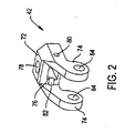
図2および図3に最もよく示されているヒンジ42は、略矩形状の基部72を備えている。基部72は、互いに向かって内方にテーパが付された(図示されていない)上側面を備えている。2つの平行脚74が基部72の一端から外方に突出している。ヒンジ42は、脚74がシャフトの対向する平行平面の上にスリップ嵌合することができるように、形作られている。各脚74は、(図番が付されていない)丸形状の自由端を有するように、形成されている。
The
ヒンジ42は、矩形状長孔76が基部72を貫通するように、形成されている。長孔76の長軸は、脚74の長軸と平行である。長孔76は、ブレード44と一体の(以下に述べる)タブ140を受け入れるように、寸法決めされている。開口78が、ヒンジ基部72の上部を貫通している。開口78は、長孔76まで延在している。同軸開口80(1つの開口80が示されている)が、脚74が基部72から延出するヒンジ42の両側を貫通している。各開口80は、基部72を部分的に横切っている。脚74が隣接して延出する基部72の面には、2つの溝82(1つの溝82が示されている)が形成されている。各溝82は、開口80の半径と等しい曲率半径を有しており、開口80を貫通する共通軸を中心として湾曲している。各脚74には、貫通孔84が形成されている。脚貫通孔84は、互いに同軸である。
The
ブレード44をヒンジ42に取外し可能に保持する(図3に示されている)アセンブリは、スリーブ状のブッシュ88を備えている。ブッシュ88は、ヒンジ開口78に圧入されている。ロックピン90が、ブッシュ内で上下に運動するように、ブッシュ88内に配置されている。ロックピン90は、ブレード44と一体の孔142(図5)内に着座するように設計された先端92を有している。先端92の上方において、ロックピン90は、リップ94を有している。リップ94は、先端92の本体から半径方向外方および周方向に突出している。リング状のリテーナ96が、ヒンジ42から離間したブッシュ88の端内に圧入されている。これらの構成要素は、先端92と反対側のロックピン90の端がリテーナ96の上方に突出するように、さらに寸法決めされている。
The assembly (shown in FIG. 3) that removably holds the
螺旋バネ102が、ロックピン90の本体の周りに配置されている。バネ102は、リテーナ96の静止内面と、ロックピン90と一体のリップ94との間に延在している。バネ102は、ピン先端92をヒンジ長孔76内に保持するように付勢する力をロックピン99に加えることになる。先端92と反対側のピン90の端、すなわち、リテーナ96の上方に延在する区域は、ボタン103に取り付けられている。他の力が付与されない限り、バネ102は、ボタン103をブッシュ88の上方に保持している。この連結アセンブリは、ボタン103を引っ張ることによって、実行状態から装着状態に移行するようになっている。この場合、手動力が、先端92をヒンジ長孔76内に保持するようにピン90に加えられたバネ102の力を上回ることになる。
A
カップ取外し器30の組立時に、ヒンジ42は、各脚貫通孔84がシャフト40の(部番が付されていない)開口の個別の1つに隣接するように、位置決めされる。本発明のいくつかの態様では、これらの開口は、前端構成要素、すなわち、ヘッド38をシャフト40に保持するためにこれらのヘッドとシャフトとの間に位置するカプラー39に配置されている。ピン105が、ヒンジ孔84およびカップラー39の貫通孔を貫通し、ヒンジ42をカップラー39に枢動可能に保持するようになっている。ピン106が開口80および溝82内に着座されるようになっている。ピン106は、ブレードタブ140が長孔76に挿入される程度を制限するものである。
When the
ロッド45が、ハンドル46をヒンジ42に接続している。ロッド45は、部番が付されていないアクチュエータを備えているとよい。アクチュエータは、ヒンジ42に実際に接続されるロッドの構成要素である。ロッド45および付随するアクチュエータは、ハンドル46の線状移動時に、ヒンジ42を脚開口84を貫通する軸を中心としてシャフト40の上下方向に旋回させるように、構成されている。ヒンジを旋回させる構成要素の正確な構造は、本発明の一部をなすものではない。
A rod 45 connects the handle 46 to the
以下、図4〜図7を参照して、ブレード44について説明する。ブレード44は、細長の本体132を備えている。本体132は、近位端134を有しており、該近位端から2つの平行側面136が延在している。矩形開口138が、近位縁134の前方に位置するように、本体の近位部分に形成されている。ブレードタブ140が、本体開口138内に溶接されるかまたはそれ以外の方法によって固定されている。タブ140は、本体132の内面からシャフト40に向かって内方に延在している。タブ140は、閉鎖端孔142を有するように形作られている。閉鎖端孔142の開口が図5に示されている。孔142は、タブ140の近位側を向く面から内方に延在している。
Hereinafter, the
ブレード本体132,すなわち、タブ140の遠位側に位置するブレードの少なくとも一部は、長軸(近位−遠位軸)および横軸(側−側軸)の両方が湾曲するように、形成されている。さらに具体的には、ブレード本体は、該本体の内面に沿って、これらの軸に沿った共通の曲率半径を有するように、形成されている。この曲率半径は、典型的には、取外し器30によって取り外される寛骨臼カップ34によって画定される球の曲率半径よりもわずかに4mm大きくなっている。本発明の多くの態様では、ブレード本体32の内面のこれらの軸に沿った共通の湾曲半径は、寛骨臼カップ34の曲率半径よりも2mm未満大きくなっている。ブレード本体132は、遠位端の中央部が本体の両側よりもさらに遠位側に延在するように、さらに形成されている。中央部分の近位側において、ブレード本体の両面は、隣接する本体の側面136に対して近位側にテーパが付されている。
歯150が、本体132の遠位端から遠位側前方に延在している。歯150がブレード本体の延長部なので、歯150(ならびに以下に述べる他の歯)は、ブレード本体の長手方向曲率半径および横方向曲率半径上に位置している。各歯150は、すくい面152およびクリアランス面156を有している。すくい面152は、歯が切除される材料に対して移動するときに切除される材料の方を向く歯面である。クリアランス面156は、歯が切除される材料に対して移動するときに切除される材料と反対側を向く面である。すくい面152およびクリアランス面156は、歯150の刃先である縁154において交わっている。歯150a〜150fおよび歯150i〜150nのクリアランス面156は、隣接する歯のすくい面が現れる線に沿ってブレード本体から現れる。外側歯、すなわち歯150a,150nのすくい面は、ブレード本体の側面136によって画定されたブレード本体面の延長部である。従って、本発明のブレードの歯150は、ブレード側面136から横方向外方に突出していない。ブレード44は、本体長軸の両側に最も近い2つの歯、すなわち、歯150g,150hが、これらの歯のクリアランス面156がブレード本体132の長軸と直交する共通線から現れるように、形作られている。
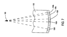
外側の2つの歯、すなわち、歯150a,150nのすくい面152は、平行面内にある。内側の歯、すなわち、歯150b〜150mのすくい面は、非平行面内にある。これらの歯150b〜150mのすくい面152の各々は、2つの軸によって画定された面内にある。これらの面の各々の第1の軸は、ブレード本体132の長軸と平行の軸である。これらの面の各々の第2の軸は、第1の軸と交差し、かつブレード本体の長軸および横軸の共通半径によって画定された球の中心と交差している。従って、ブレード44が寛骨臼カップ取外し器30に取り付けられたとき、この中心は、カップ取外し器ヘッド38でもある。それ故、この中心は、(ブレード44が作用する)寛骨臼カップ34の中心でもある。これは、図7に示されている。この図において、歯150a〜150mの刃先154の延長部を表す点線が共通点160において交わることが示されている。これらの点線は、歯150b,150c,150f,150h、150lのすくい面の平面を画定する第2の軸の延長部でもある。図面の複雑さを最小限に抑えるために、残りの歯の延長線は、示されていない。
The outer two teeth, i.e., rake
本発明のカップ取外し器30は、最初、ブレード44をヒンジ42に装着することによって、使用の準備が整えられる。これは、ボタン103を上に引っ張ることによって、達成される。ボタンに加えられたこの手動力が、ピン先端92をヒンジ長孔76内に保持するバネ102の力を上回ることになる。いったんピン先端92がヒンジ長孔76から離れる方に後退したなら、ブレードタブ140をヒンジ長孔76内に着座させることによって、ブレード42がヒンジに取り付けられる。いったんブレードタブ孔142がピン90と真っ直ぐに並んだなら、ボタン902が解放される。ロックピン90に加えられるバネ102の力がピン先端92をブレードタブ孔142内に保持する。このようにして、ブレードがヒンジ42に取外し可能に連結されることになる。
The cup remover 30 of the present invention is ready for use by first attaching the
次いで、カップ取外し器30が、ドライバー56に連結される。具体的には、カップ取外し器30は、取外し器ヘッド38が(取り外すことを意図する)寛骨臼カップ34の中心空洞内に着座するように、位置決めされる。もしライナーが設けられているなら、該ライナーは、典型的には、カップ34内へのヘッド38の着座の前に取り除かれることになる。
The
ドライバー56の作動の結果、ブレード44の前後振動が生じる。歯の方位に起因して、すくい面は、歯が作用する骨の表面に対して0°のすくい角を有している。その結果、各刃先154の全体が、ブレードが作用するカップに隣接する未切除骨に作用することになる。従って、歯の掃引中、径方向に位置していないすくい面を有するブレードと比較して、本発明のブレードのすくい面は、すくい面が回転する相手の骨またはセメントに対してより十分に押圧されることになる。骨をこのように押圧するすくい面の利点は、その結果として、比較的大きい塊の骨を寛骨臼カップ34の周りの領域から切り取ることができる点にある。
As a result of the operation of the driver 56, longitudinal vibration of the
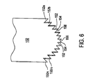
図8〜図11は、本発明の第2のブレード180を示している。ブレード180は、ブレード本体180と実質的に同一の本体182を有している。本体182は、互いに反対側を向く平行側面184を有しており、その縁が図9に示されている。タブ140が、ブレード本体182から突出している。
8-11 illustrate a
歯190が、ブレード本体182の遠位端から延在している。各歯190は、すくい面192およびクリアランス面196を有している。(各面の2つに部番が付されている)。各歯のすくい面およびクリアランス面は、歯の刃先194で交わっている(2つの刃先に部番が付されている)。各すくい面192は、以下の平面、すなわち、該平面の第1の軸がブレード本体182の長手方向中心面と平行になっている、平面内に着座している。最外歯、すなわち、歯190a,190jのすくい面192は、歯が延出するブレード本体182の側面184と共面である。内側歯、すなわち、歯190b〜190iは、これらの歯のすくい面の平面を画定する第1の軸が、すくい面152の第1の軸と同様、ブレード本体182の長手方向中心面と平行の線であるように形成されている。
歯190b〜190iは、互いに隣接する歯のすくい面192が以下の平面、すなわち、該平面の第2の軸が共通点において交わらない平面上に位置するように、さらに形成されている。代わって、歯190b〜190iのすくい面192は、以下の平面、すなわち、該平面の第2の軸が(ブレード180を有する工具30が用いられる)寛骨臼カップ34の中心から外方に放射状に延在する線に対して傾斜する平面上に位置している。さらに具体的には、歯190bのすくい面192は、線198bによって表される軸上に位置していることが分かるだろう。線198bは、球の中心を貫通する平面、すなわち、線202によって表される平面に向かって近位側に延在している。また、線202は、ブレード本体192に沿った長手方向(近位−遠位)中心面を表している。
The
この中心面は、ブレード本体182を横切る横軸と直交していることを理解されたい。これは、歯190bの長手方向中心面と直交する断面において、ブレード刃先194から近位側後方に進むにつれて、歯190bの外面の幅が、歯190bの下側内面の幅よりも長くなることを意味している。換言すれば、歯198bのすくい面192は、以下の軸、すなわち、歯の互いに反対側を向く外面および内面から延在し、ブレード本体182の長手方向中心面の方に向かう軸上に位置することになる。
It should be understood that this center plane is orthogonal to the transverse axis across the
歯190c、すなわち、ブレード本体の長手方向中心面のより近くに位置する(歯190bに隣接する)歯は、線198cによって表わされる軸上に位置するすくい面192を有している。線198cは、(カップ34の球の中心を貫通する)平面202から離れる方に向かって近位側に延在している。従って、歯の長手方向中心面と直交する断面において、歯190cの刃先から遠位側に進むにつれて、歯190cの内面の幅は、歯190cの外面の幅よりも長くなっている。歯196cのすくい面192の第2の軸を代替的に記述すれば、この軸は、歯の互いに反対側を向く内面および外面から延在し、ブレード本体182の長手方向中心面から離れる方に向う軸である。
The
歯190dは、ブレード本体182の長手方向中心面のより近くに位置する(歯190cに隣接する)歯である。歯190dは、歯190bのすくい面と同様、以下の軸、すなわち、近位側に進むにつれて、球の中心と交わる面に向かう軸上に位置するすくい面を有している。これは、歯190dのすくい面192の第2の軸が、線198dによって表されるように、歯190dの外面および内面から延在し、ブレード本体の長手方向中心面に向かって傾斜していることを意味している。歯190eは、図11のブレードの右側において、ブレード本体182の長手方向中心面に最も近い歯である。歯190eは、歯190cの勾配、すなわち、第2の軸、具体的には、歯190cと同一方位にある勾配、すなわち、第2の軸を有するすくい面を有している。
The
図11に示されているように、ブレード本体182の長手方向中心面の左側の歯190f〜190iは、長手方向中心面に対して対称的に反対側に位置する歯のすくい面の勾配、すなわち、第2の軸と逆の勾配、すなわち、第2の軸を有するすくい面を有している。従って、歯190eと対称的な歯190fは、線198fによって表される軸上に位置するすくい面を有している。線198fは、線202によって表されるブレード本体の長手方向中心線に向かって内方に延在している。ここでも、これらの基準線の各々は、すくい面によって形成された歯の内面および外面から延在する軸の方向にあることを理解されたい。歯190dと対称的な歯190gは、線198gによって表されるすくい面を有している。線198gは、ブレード本体の長手方向中心面に対して外方に延在している。歯190hは、歯190cと対称的な歯である。従って、歯190cが外方に延在する軸上に位置するすくい面を有する場合、歯190hは、線198hによって表される内方に延在する軸上に位置するすくい面を有することになる。歯190b,190iは、ブレード本体182の長手方向中心面を中心として、互いに対称的である。歯190bがブレード本体の長手方向中心面に向かって内方に傾斜するすくい面を有する場合、歯190iは、ブレード本体の長手方向中心面から外方に延在する線198iによって表される軸上に位置するすくい面を有することになる。
As shown in FIG. 11, the teeth 190 f to 190 i on the left side of the longitudinal center plane of the
図11Aは、この傾斜のさらなる理解をもたらすものである。図11Aにおいて、歯190b,190cの傾斜を画定する軸は、実線198b,198cによって表されている。一点鎖線199b,199cは、ブレード180の仮想中心、すなわち、点197から延在する径方向線である。この中心は、ブレードが用いられるカップの中心である。共通面において、径方向線199bは、軸線198bと交差している。この交差の角度が傾斜角である。本発明の多くの態様において、勾配と呼ばれることもあるこの傾斜角は、30°未満、多くの場合、20°未満の角度である。本発明の図示されている態様では、互いに隣接するすくい面192の傾斜角は、等しくなっている。
FIG. 11A provides a further understanding of this slope. In FIG. 11A, the axes that define the inclination of the
ブレード180は、ブレード44を取り付けたのと同じ方法を用いて、工具30に取り付けられる。次いで、前述の方法を用いて、工具30の使用の準備が整えられる。ドライバー56の作動の結果、ブレード180の振動が生じる。ブレードが骨に対して移動すると、刃先が骨を剪断することになる。図11に示されるブレード180が右側に移動したとき、歯190a〜190eの刃先が骨を剪断する。歯190b,190dのすくい角の角度に起因して、これらのすくい面に隣接する破片は、ブレード180の内面に向かって移動する。これによって、これらの歯の刃先に対する破片の堆積が最小化されることになる。同時に、歯190c〜190eと一体のすくい面192の方位に起因して、これらのすくい面に隣接する破片は、ブレードの外面に向かって押し出される。図11に示されるブレード180が左側に移動したとき、歯190f〜190jの刃先192が骨を剪断する。歯190f,190hと一体のすくい面192の方位に起因して、これらの歯に隣接する破片は、ブレード180の内面に向かって押し出される。
The
歯190g,190iと一体のすくい面192の方位に起因して、これらの歯に隣接する破片は、ブレード180の外面に向かって押し出される。ブレードの内面および外面に向かって破片をこのように押し出すことによって、刃先に対する破片の堆積が最小限に抑えられることになる。破片の堆積を最小限に抑える結果として、これらの破片の存在による骨(またはセメント)を除去するプロセスの効率の低下を同じように軽減させることができる。
Due to the orientation of the
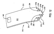
以下、図12〜図15を参照して、本発明のカップ取外し器30の一部として用いられる第3のブレード210について説明する。ブレード210は、本体212を備えている。本体212は、前述のブレード本体132と同一の基本形状を有している。本体212は、互いに反対側を向く側面213を有しており、これらの側面の少なくとも縁が図12に示されている。タブ140が、本体212の内面から外方に突出している。
Hereinafter, the
歯214、個別的には、歯214a〜214jは、本体212の遠位端から遠位側前方に突出している。各歯214は、すくい面216(図12において2つのすくい面に部番が付されている)およびクリアランス面220(図14において3つのクリアランス面に部番が付されている)を有している。歯214のすくい面216およびクリアランス面220は、それぞれ、歯の刃先218(図14において2つの刃先に部番が付されている)から近位側後方に延在している。本発明の図示されている態様では、最外歯、すなわち、歯214a〜214jのすくい面は、各々、側面213と共面であり、該側面213から遠位側前方に延在している。歯214b〜214iは、ブレード44の歯150b〜150mのすくい面152と同様のすくい面216を有している。歯214b〜214iのすくい面214の各1つは、ブレード本体の長軸と平行の第1の軸上および取外し器30が用いられるカップ34によって画定された球の中心から半径方向に延在する第2の軸上に位置している。
ブレード210は、通路または分岐と称されることもある溝が歯のいくつかのクリアランス面から近位側に延在するように、さらに形成されている。さらに具体的には、ブレード本体212の外面が3つの溝230,232,234を画定するように形作られていることが分かるだろう。溝230は、歯214bと一体のクリアランス面220の外縁から近位側に延在している。溝232は、歯214dのクリアランス面220の外縁から近位側に延在している。溝234は、歯214hのクリアランス面220の外縁から近位側に延在している。
The
ブレード210は、歯のいくつかのクリアランス面から近位側に延在する3つの溝を本体の内面に有するように、さらに形成されている。
The
溝236は、歯214cのクリアラス面220の内縁から近位側に延在している。溝238は、歯214gのクリアランス面220の内縁から近位側に延在している。溝240は、歯214iのクリアランス面220の内縁から近位側に延在している。
The
ブレード210は、溝230〜240の各々の深さが該溝が形成された面に沿って近位側に延在するにつれて減少するように、形成されている。また、ブレード210は、溝230〜240の幅が、該溝が延出するクリアランス面の幅よりも短くなるように、さらに形成されている。各溝は、溝が形成された歯の刃先218から内方に離間するように、位置決めされている。従って、溝の存在によって、関連する刃先の長さは、短縮されないことになる。ブレード本体212の内面および外面に対して溝が介在することをさらに理解されたい。換言すれば、内面(または外面)に形成された2つの隣接する溝間において、溝が外面(または内面)に形成されることになる。
The
ブレード210が取り付けられたカップ取外し器30は、前述したブレード44,180と同様に、使用の準備が整えられる。ブレード210を有するカップ取外し30が作動されると、刃先218が寛骨臼カップ34に対する骨を剪断する。その結果、骨が除去されることになる。溝230〜240は、この骨除去プロセスによって形成された破片を歯214の刃先218から外に流出させる導管として機能する。破片に対して該破片を刃先から流出させる導管が設けられているので、破片は、刃先に隣接して堆積しないことになる。これによって、歯の刃先218に隣接して破片が堆積することによって骨除去プロセスの効率を低下させる程度が抑制されることになる。
The
本発明の好ましい態様では、溝230〜240が形成される方法に起因して、溝の深さは、実質的に同一である。 In a preferred embodiment of the invention, the depth of the grooves is substantially the same due to the method by which the grooves 230-240 are formed.
図16〜図19は、本発明のカップ取外し器30に組込み可能な第4のブレード250を示している。ブレード250の特徴の多くは、ブレード210の特徴と同じである。従って、これらの特徴については、繰返して述べない。ブレード210が歯214、すくい面216、刃先218、およびクリアランス面220を有しているのに対して、ブレード250は、歯254、すくい面256、刃先258、およびクリアランス面260を有している。
16-19 illustrate a
ブレード250は、ブレード本体212に形成された溝270〜280を有している。溝270〜274は、ブレード250の外面に形成されている。さらに具体的には、溝270は、歯254bに跨って延在している。溝272は、歯254dに跨って延在している。溝274は、歯254hに跨って延在している。溝276〜280は、ブレード250の内面に形成されている。さらに具体的には、溝276は、歯254cに跨って存在している。溝278は、歯254gに跨って存在している。溝280は、歯254iに跨って存在している。
The
溝270〜280は、以下の点において、すなわち、溝270〜280が形成される歯254のクリアランス面の幅の全体にわたって延在している点において、溝230〜240と異なっている。 Grooves 270-280 differ from grooves 230-240 in the following respects, i.e., extending across the width of the clearance surface of tooth 254 where grooves 270-280 are formed.
溝270〜280の基部を画定する凹面は、各々、2つの軸を中心としている。これらの軸は、溝270を画定するブレードの面を示す図18Aに示されている。1つの軸である長軸は、ブレードの長軸と平行である。図18Aにおいて紙面と直交するこの軸は、点286によって表わされている。図18Aに示されている第2の軸である横軸は、ブレードの仮想中心、すなわち、点287から延在する径方向線と直交する線である。この横軸、すなわち、線289は、溝の基部の長軸と交差する半径方向線288と交差している。一般的に、これらの溝は、溝の長さに沿ったどの点においても、ブレード本体の全厚みの50%を越える深さを有しないように、形成されている。前述したように、各溝を横切る横軸は、直線である。従って、図18Aに示されているように、溝の下のブレードの部分の厚みは、溝の長軸の下方において最も薄くなっている。
The concave surfaces defining the bases of the grooves 270-280 are each centered on two axes. These axes are shown in FIG. 18A, which shows the face of the blade that defines the
図18Aは、ブレード250の遠位端の平面図である。3つのクリアランス面260が示されており、これらのクリアランス面260から溝270,278,280が近位側後方に延在している。溝278が延出するクリアランス面と相補的なすくい面との交差によって画定される刃先は、実線セグメント291として示されている。実線セグメント291と共線関係にある破線セグメント292は、溝280が形成された歯のすくい面と溝270が延出する隣接クリアランス面との交差を表している。図18Aにおいて、溝270のクリアランス面によって形成された刃先の右側に、溝278が形成された歯の(図示されていない)すくい面が形成されている。破線セグメントは、コーナを表しており、該コーナから、溝270が形成されたクリアランス面が次の歯のすくい面の前方に延在している。破線293と共線関係にある実線287は、次の歯のすくい面と相補的なクリアランス面280とによって形成された刃先を表している。この特定のクリアランス面は、溝278が延出するクリアランス面である。
FIG. 18A is a plan view of the distal end of the
図18Aでは、外側溝270は、該溝の基部から外方に傾斜する側壁を有するものとして示されている。内側溝278,280は、該溝の基部から内方に傾斜する側壁によって画定されるものとして示されている。これは、例示にすぎない。実際には、溝を形成するために砥石車をブレードに押し付ける結果として、通常、溝には平行側壁が形成されることになる。
In FIG. 18A, the
カップ取外し器30は、カップ取外し器30の使用の準備を整えるための前述の方法と同じ一般的な方法によって、ブレード250と共に用いるための使用の準備が整えられる。
The
ブレード250を備えるカップ取外し器259が作動されると、ブレード歯254の刃先258が、寛骨臼カップ34を股間節に保持している骨を剪断することになる。溝270〜280は、この剪断プロセスによって形成された骨破片を歯刃先258から流出させる比較的大きい溝として機能する。これによって、ブレード刃先に隣接する骨片除去効率の低下をさらに抑止することができる。
When the cup remover 259 with the
溝270〜280は、該溝に関連するクリアランス面の全幅を横切って延在している。従って、クリアランス面260の高さが低下する。これによって、クリアランス面260によって画定される刃先258の長さも短くなる。しかし、前述したように、本発明の多くの態様では、ブレード250は、溝の存在がクリアランス面の高さを低下させず、溝が存在しない歯と比較して関連する刃先の長さが50%を超えるように、形成されている。この特徴によって、隣接する歯の交互の側面に溝が配置されていても、ブレードの骨と対向するブレード区域が刃先を有することが確実になる。
Grooves 270-280 extend across the entire width of the clearance surface associated with the groove. Accordingly, the height of the
図20および図21は、本発明の第5のブレード290を示している。ブレード290は、単一片ブレード本体292を備えている。ブレード本体292は、略矩形プレートの形態にある足294を有している。足294は、ヘッドを貫通する開口296を有するように、形成されている。開口296は、修正されたキー孔開口である。この開口は、円形の中心部および中心部から半径方向に突出する延長部を有している(開口部分には部番が付されていない)。延長部の幅は、中心部分の直径よりも狭くなっている。開口296は、延長部開口が足294の縁内に開いているという点において修正されたキー孔開口である。
20 and 21 show a
ブレード足294は、ブレード290が取り付けられるカップ取外し器のヒンジ内に形成された相補的長孔内に嵌合するように、寸法決めされている。図20にのみ示されているピン297が、ブレードを長孔に保持するようになっている。ピン297は、シャフト298、カラー302、およびヘッド304を有している。シャフト298は、ブレード開口296の延長部の幅よりも小さい直径を有している。カラー302は、シャフト298の直径およびブレード開口296の延長部の幅よりも大きい直径を有している。ヘッド304は、カラー302の直径よりも大きい直径を有している。バネまたは他の付勢部材が、カラー302がブレード開口296の中心部内に着座するように、ピンを常時ヒンジに保持している。ブレード開口296内へのピンカラー302のこの着座が、ブレード290を寛骨臼カップ取外し器の残りに離脱可能に保持することになる。ブレードは、その長軸に沿ってピンを移動させ、ピンシャフトをブレード開口296の中心部分と真っ直ぐに並べることによって、取り外されるようになっている。具体的には、この後、ブレードをヒンジから外に摺動させることによって、ブレードを取り外すことができる。このプロセス中、ブレード開口296の延長部を形成するブレード足294の区域は、ピンシャフト298の両側に沿って摺動することになる。
幹部312が、足294から遠位側前方に延在している。幹部312は、その長軸および横軸の両方に沿って湾曲したブレード本体の一部である。本発明の図示されている態様では、ブレード290は、ヘッド294と幹部312との間のコーナの周りに延在する補強ウエブ310を有するように、形成されている。
A
ブレード幹部312は、幹部の長さに沿って変化する幅を有している。具体的には、実質的に幹部の殆どに沿って、幹部の幅は、一定である。本発明の図示されている態様では、幹部のこの部分は、足294を横切る幅と等しい幅を有している。ブレード本体の遠位端に隣接する箇所において、ブレード本体の側面は、ブレードに沿った長軸から外方に拡張または傾斜している。ブレード本体は、ヘッド318を有しており、その幅は、ヘッドが延出する幹部312の幅よりも大きい。本発明の図示されている態様では、面314は、本体幹部312の平行側面である。面316は、外側に拡がった側面である。本発明の図示されている態様では、ブレードは、各面316が凹状であるように、形成されている。面320は、ブレードの最遠位側面である。側面320は、互いに平行である。
The blade stem 312 has a width that varies along the length of the stem. Specifically, the width of the trunk is constant substantially along most of the trunk. In the illustrated embodiment of the invention, this portion of the trunk has a width equal to the width across the
ブレード290は、歯324a〜324pを有するように形成されている。各歯は、刃先を形成するように交差するすくい面およびクリアランス面を有している。平行側面320は、最外歯324a,324pのすくい面を形成している。概して、歯324a〜324pは、ブレード210の歯214a〜214jと同様である。ブレードの少なくとも1つの表面上に、ブレード本体に沿ってクリアランス面から近位側に延在する溝326を有する少なくとも1つの歯が形成されている。本発明の図示されている態様では、ブレード290は、溝326が歯324c,324e,324g,324j,324l,324nの外向き面から内方に延在するように、形成されている。図示されていないが、ブレード290は、溝が歯の少なくともいくつかの内向き面から内方に延在するように、さらに形成されているとよい。
ブレード290は、本発明の前述した態様よりもさらに多くの歯を備えている。これは、ブレードの掃引ごとに、ブレードが作用するカップ34に隣接する空間からさらなる骨/セメントを切り取ることができることを意味している。ブレード290は、ブレードの近位部、すなわち、足294の幅を前述の幅よりも大きくすることなく、これらの追加的な歯を有することができる。従って、ブレード290は、該ブレードを収容するように特別に寸法決めされた寛骨臼カップ取外し器と共に用いる必要もなく、切除効率を高めることができる。
The
図22および図23は、本発明の第6のブレード340を示している。ブレード340は、ブレード本体342を備えている。ブレード本体342は、ブレード290の足294と本質的に等しい足344を備えている。
22 and 23 show a
ブレード本体342は、足344の遠位側前方に延在する幹部346を備えている。幹部346は、互いに反対側を向く外面348および内面354を有するように、形成されている。足344の略2〜20mm前方において、幹部は、外向き面348の幅が、内向き面354の幅よりも略1〜10mm小さくなるように、形成されている。互いに反対側を向くテーパ側面350が、各外面の端から内向き面の隣接端に延在している。各側面350および隣接する内向き面354が交わり、側縁352を画定している。互いに反対側を向く側縁352(図22および図23において1つの側縁のみが示されている)は、ブレード本体の幹部に沿って円弧状に延在している。
ブレード340は、溝360,362,364を備える歯358を有するものとして示されている。歯358は、歯214と同様である。溝360,362,364は、溝230,232,234と同様である。
ブレード340は、前述したブレードと同じように用いられる。ブレード340の利点は、ブレードが振動したとき、ブレードの近くに位置する側縁352が軟組織を切除することにある。この組織は、取り外されるカップの周りに形成される可能性のある繊維組織を含んでいる。
The
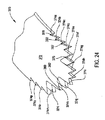
図24は、本発明の追加的ブレード370の遠位端を示している。ブレード370は、ブレード本体372を有している。ブレード370に、歯374a〜374pが形成されている。各歯は、すくい面376およびクリアランス面382を有している(各面の2つに部番が付されている)。各歯のすくい面376およびクリアランス面382は、歯の刃先380において交わっている。本発明のこの態様では、歯374b〜374dおよび歯374m〜374oは、正のすくい角を有している。従って、これらの歯のすくい面は、ブレード370の長軸から外方に延在しているように見える。歯374a,374e〜374l,374pは、0°、すなわち、中立のすくい角を有している。
FIG. 24 shows the distal end of an
本発明のこの態様では、歯374b〜374dおよび歯374m〜374oは、横方向から離れる方に向けられていても、これらの歯が作用する骨またはセメントを掘り起こさない。代わって、骨/セメントは、前述したように、さらに効率的な剪断作用によって除去されることになる。
In this aspect of the invention,
ブレード370の歯374a〜374pは、いずれも、本発明の前述した他の態様の歯と同じように、歯のクリアランス面382が関連する歯のすくい面の遠位側前方に突出しないように、さらに形成されていることをさらに理解されたい。
None of the
前述の説明は、本発明の特別の態様に向けられている。本発明の代替的態様は、記載されている特徴と異なる特徴を有していてもよい。例えば、図示されている本発明のブレードが有する歯の数は、例示的であり、制限するものではないことを理解されたい。 The foregoing description is directed to specific aspects of the invention. Alternative embodiments of the invention may have different features than those described. For example, it should be understood that the number of teeth that the illustrated blade of the present invention has is exemplary and not limiting.
さらに、ブレードの特徴は、取り換えられてもよい。具体的には、本発明のいくつかの態様において、ブレードは、以下の歯、すなわち、傾斜したすくい面を有し、かつ溝230〜240または溝270〜280と同様の溝を有するようにさらに形成された歯を有していてもよい。本発明のいくつかの態様において、歯に形成された溝は、異なる幅を有していてもよい。具体的には、1つまたは複数の歯に近位側に延在するにつれて幅が狭くなる溝を設けることが望ましいことがある。これは、もし溝を有する歯のいくつかにブレードの全幅に延在する刃先を設けることが望ましい場合に有益である。同じブレードのさらに他の歯には、より長い幅溝が形成されていてもよい。従って、これらの歯は、比較的短くて溝の存在によって一部が切り取られた刃先を有することになる。しかし、これらの歯と一体の断面積の大きい溝は、該溝が形成されたブレードの遠位端から比較的多量の破片を受け入れ、離れる方に導くことができる。 Further, the blade features may be interchanged. Specifically, in some aspects of the invention, the blade further has the following teeth: a sloped rake face and a groove similar to grooves 230-240 or grooves 270-280. You may have the tooth formed. In some aspects of the invention, the grooves formed in the teeth may have different widths. In particular, it may be desirable to provide one or more teeth with a groove that decreases in width as it extends proximally. This is beneficial if it is desirable to provide some of the teeth with grooves with cutting edges that extend the full width of the blade. Longer width grooves may be formed in still other teeth of the same blade. Thus, these teeth have a cutting edge that is relatively short and partially cut off by the presence of a groove. However, the large cross-sectional groove integral with these teeth can accept a relatively large amount of debris from the distal end of the blade in which the groove is formed and guide it away.
同様に、本発明のいくつかのブレードは、全ての歯ではなく、いくつかの歯がブレード180の歯の勾配、すなわち、傾斜を有するように設計されていてもよい。本発明のこの実施形態のいくつかの好ましい態様では、全ての歯よりも少ない数の歯が1つの傾斜または勾配を備えており、1つの傾斜を備えるこれらの歯は、外面から内面に延在しながら、基準球の中心、すなわち、ブレード本体の長手方向中心面と交差する面から離れる方に延在するすくい面を有するように形成されている。これらのすくい面は、例えば、図11のブレードのすくい面198c,198 e,198g,198iである。これらのすくい面を有する歯を設けることによって、カップ取外しプロセスにおいて、カップおよびブレードからの破片の押出しが容易になる。
Similarly, some blades of the present invention may be designed such that some, but not all, of the teeth have a tooth gradient, or inclination, of the
本発明のさらに他の実施形態では、複数の歯が、1つの傾斜を備えており、1つの傾斜を備える複数の歯は、内面から外面に延在しながら、基準球の中心、すなわち、ブレード本体の長手方向中心面と交差する平面に向かって延在するすくい面を有するように形成されている。これらのすくい面は、例えば、図11のブレードのすくい面198b,198d,198f,198hである。 In yet another embodiment of the present invention, the plurality of teeth includes a slope, and the plurality of teeth with a slope extends from the inner surface to the outer surface while the center of the reference sphere, ie, the blade It is formed so as to have a rake face extending toward a plane intersecting the longitudinal center plane of the main body. These rake faces are, for example, the rake faces 198b, 198d, 198f, and 198h of the blade of FIG.
同様に、本発明のいくつかの態様では、複数の互いに隣接する歯が歯190bの傾斜を有していてもよい。本発明のいくつかの態様では、複数の互いに隣接する歯が歯190cの傾斜を有していてもよい。本発明のいくつかの態様では、歯190bの傾斜または歯190cの傾斜を有する歯が、どのような傾斜または勾配も有していない(すなわち、互いに反対側の外面と内面との間に延在する軸が本体の長手方向中心面と平行になっている)歯に隣接していてもよい。従って、本発明の全ての態様において、歯の外面から歯の内面に延在しながら長手方向中心面に向かって延在するすくい面に沿った軸を有する歯が、反対方向を向く軸を有する歯に必ずしも隣接している必要がない。
Similarly, in some aspects of the invention, a plurality of adjacent teeth may have a slope of
さらに、ブレード本体の円弧長さが図示されているものと異なっていてもよいことを理解されたい。本発明の多くのカップ取外し器30は、複数のブレードを単一の手順に用いることが想定されている。最初に浅い切込みまたは切口を寛骨臼カップ34の周りに形成するために、10°から45°の間の円弧を画定する第1のブレードが用いられるとよい。いったんこの切込みが形成されたなら、少なくとも45°以上、典型的には、90°以下の円弧を画定するブレードが、カップ取外し器に装着されるとよい。このブレードを用いて、最終的な切込みを形成することになる。多くの場合、この切込みは、カップ34の遠位端チップの周りまで延在していない。この切込みによって、カップとその下の骨との間に小さい幹部分が残される。この幹部分は、容易に折れ、これによって、カップが装着された股間節からカップを取り外すことができる。いくつかの手順では、本発明の寛骨臼カップによって形成された切込みによって、カップをその下の骨から完全に分離させることができる。 Furthermore, it should be understood that the arc length of the blade body may differ from that shown. Many cup removers 30 of the present invention are intended to use multiple blades in a single procedure. A first blade defining an arc between 10 ° and 45 ° may be used to initially form a shallow incision or cut around the acetabular cup 34. Once this incision has been made, a blade defining an arc of at least 45 ° or more, typically 90 ° or less, may be attached to the cup remover. This blade will be used to form the final cut. In many cases, this notch does not extend around the distal end tip of the cup 34. This incision leaves a small trunk between the cup and the underlying bone. This stem portion can be easily folded, so that the cup can be removed from the groin where the cup is attached. In some procedures, the incision formed by the acetabular cup of the present invention allows the cup to be completely separated from the underlying bone.
本発明の記載されている態様では、ブレード歯は、中心から外方に延在する線上において、ブレードの中心から近位側後方に延在することが想定されている。本発明の代替的態様では、歯または歯の少なくとも一部は、円弧上に配置されていてもよい。この円弧の中心は、典型的には、ブレードを通る長軸の延長部と交差する点である。 In the described aspect of the invention, it is envisaged that the blade teeth extend proximally rearward from the center of the blade on a line extending outwardly from the center. In an alternative aspect of the invention, the teeth or at least some of the teeth may be arranged on an arc. The center of this arc is typically the point that intersects the long axis extension through the blade.
また、本発明の記載されている態様では、各ブレードの外側歯のすくい面は、概して、ブレード本体の側面の延長部と平行である。これは、例示であって、制限するものではない。本発明の代替的構成では、これらのすくい面は、側面と連続しない面上にあってもよい。例えば、ブレード44の一態様として、歯150a,150nは、隣接する歯150b,150mのすくい面と方位が同様のすくい面を有するように、設けられてもよい。
Also, in the described aspect of the present invention, the rake face of the outer teeth of each blade is generally parallel to the side extension of the blade body. This is illustrative and not limiting. In an alternative configuration of the invention, these rake surfaces may be on a surface that is not continuous with the side surfaces. For example, as one aspect of the
本発明の前述の態様では、歯は、0°のすくい角を有している。これは、本発明の範囲を制限するものではない。本発明の代替的態様では、歯は、正のすくい角、場合によっては、負のすくい角を有していてもよい。例えば、ブレード44の代替的態様は、前述した面と異なる面上にあるすくい面を備える歯を有していてもよい。本発明のこれらの態様では、もし歯が正のすくい角を有しているなら、各すくい面は、以下の平面、すなわち、その1つの軸がブレードが作用する寛骨臼カップの仮想中心から延在する平面上に配置さされるとよい。平面を画定する第2の軸は、ブレードを通る長軸の延長部に収斂する線に沿って位置する。歯が正のすくい角を有するように構成された本発明の態様では、平面を画定するこれらの線とブレード長軸の延長線とが交わる点は、ブレードの遠位端の前方に位置することになる。
In the foregoing aspect of the invention, the teeth have a rake angle of 0 °. This does not limit the scope of the invention. In an alternative aspect of the invention, the teeth may have a positive rake angle, and in some cases a negative rake angle. For example, an alternative embodiment of the
同様に、溝、分岐、または通路を有する本発明の図示されている態様のいくつかは、ブレードの各側に3つの溝を有するものとして示されている。これは、単に例示を目的とするものである。ブレードが溝を備える本発明の他の態様は、ブレードの各側に3つ未満または4つ以上の溝を有していてもよい。同様に、溝を有するブレードの互いに反対側を向く内面および外面の各々は、必ずしも同数の溝を有する必要がない。また、本発明の全ての態様において、各溝の深さは、必ずしも、溝がブレードの遠位端から近位側に延在するにつれて、溝の長さに沿って一様に減少する必要がない。本発明のいくつかの態様では、溝の1つまたは複数の深さは、溝の長さに沿って実質的に一定であってもよい。 Similarly, some of the illustrated aspects of the invention having grooves, branches or passages are shown as having three grooves on each side of the blade. This is for illustrative purposes only. Other aspects of the invention in which the blade is provided with grooves may have less than three or more than three grooves on each side of the blade. Similarly, each of the inner and outer surfaces facing away from each other of a blade having a groove need not necessarily have the same number of grooves. Also, in all aspects of the present invention, the depth of each groove need not necessarily decrease uniformly along the length of the groove as the groove extends proximally from the distal end of the blade. Absent. In some aspects of the invention, the depth or depths of the grooves may be substantially constant along the length of the grooves.
ブレードに溝が形成される本発明の態様では、各溝は、必ずしも、溝が形成されるブレードの長軸と平行の長軸を中心として配置される必要がない。本発明のいくつかの態様では、3つ以上の溝が長軸に向かって内方に傾斜していてもよい。これらの溝は、ブレードの遠位端から離間した箇所においてブレードに形成された凹みにおいて交わるようになっていてもよい。この凹みは、切除プロセスの結果として形成された破片を保持するための貯留域として機能する。同様に、溝の1つまたは複数が、近位側に延在するにつれて、ブレード長軸から外方に延在するようになっていてもよい。これらの溝は、ブレードの側面にまで延在していてもよい。従って、これらの溝は、破片をブレードから流出させる導管として機能することになる。本発明のブレードは、種々の方向に延在する溝を有していてもよい。例えば、内側に位置する溝は、凹みに延在していてもよい。ブレードの側面に隣接して位置する溝は、側面に延在していてもよい。 In the embodiment of the present invention in which grooves are formed in the blade, each groove does not necessarily have to be arranged around a major axis parallel to the major axis of the blade in which the groove is formed. In some aspects of the invention, more than two grooves may be inclined inward toward the major axis. These grooves may meet at a recess formed in the blade at a location spaced from the distal end of the blade. This indentation serves as a reservoir for holding debris formed as a result of the ablation process. Similarly, one or more of the grooves may extend outwardly from the blade major axis as it extends proximally. These grooves may extend to the side of the blade. Thus, these grooves will function as conduits that allow debris to flow out of the blade. The blade of the present invention may have grooves extending in various directions. For example, the groove located on the inner side may extend in the recess. The groove located adjacent to the side surface of the blade may extend to the side surface.
同様に、ブレードをカップ取外し器20の残りに対して離脱可能に保持するブレード特徴部は、記載されているものと異なっていてもよい。 Similarly, the blade features that releasably hold the blade against the rest of the cup remover 20 may be different from those described.
詳細に記載されている本発明のブレードは、ブレードの長軸に隣接して配置された歯が、歯の最遠位側にあるように、構成されている。これは、単なる例示であり、制限するものではないことを理解されたい。本発明のいくつかの態様では、図25Aに示されているように、複数の歯392は、ブレードの幅を横切る波パターンに配置されていてもよい。本発明のさらに他の態様では、複数の歯は、最近位歯がブレードの長軸に隣接して実際に位置するように、配置されていてもよい。図25Bのブレード410に関して示されているように、長軸の両側において、各歯412は、長軸のより近くに位置する隣接歯の前方に配置されている。従って、ブレードの最外歯、すなわち、長軸から最も遠くに位置する歯は、本質的にブレードの2つの最遠位歯である。
The blade of the present invention described in detail is configured so that the teeth located adjacent to the long axis of the blade are on the most distal side of the teeth. It should be understood that this is merely exemplary and not limiting. In some aspects of the invention, as shown in FIG. 25A, the plurality of
さらに、図25Cに示されているように、複数の歯は、ブレード420の長軸と直交して延在する線上に配置されていてもよい。ここでは、各歯422の両面は、刃先を画定する互いに向き合ったすくい面として機能する。図25Cでは、歯422の全てが正のすくい角を有するものとして示されている。これは、本発明を制限するものではない。本発明によれば、歯が中立または負の角度を有するブレードが設けられていてもよい。
Further, as shown in FIG. 25C, the plurality of teeth may be arranged on a line extending perpendicular to the major axis of the
また、寛骨臼カップ取外し器の実際の構造は、例示にすぎず、制限するものではないことを理解されたい。本発明のいくつかの電動寛骨臼カップ取外し器は、ブレードを振動させるドライバーの周りに該ブレードを割出し、回転させるアセンブリを有していなくてもよい。本発明のさらに他の寛骨臼カップ取外し器は、手動によって操作されるようになっていてもよい。これらのカップ取外し器は、ブレードがカップ取外し器の残りに固定して取り付けられるように設計されていてもよい。その結果、取外し器が作用するカップに対してブレードを作用させるために、取外し器が傾けられる。この傾斜が、ブレードをカップの上を通って傾かせることになる。 It should also be understood that the actual structure of the acetabular cup remover is exemplary only and not limiting. Some motorized acetabular cup removers of the present invention may not have an assembly that indexes and rotates the blade around a driver that vibrates the blade. Still other acetabular cup removers of the present invention may be manually operated. These cup removers may be designed so that the blade is fixedly attached to the rest of the cup remover. As a result, the remover is tilted to cause the blade to act on the cup on which the remover acts. This tilt will cause the blade to tilt over the cup.
同様に、本発明のいくつかの態様では、ブレード本体の長軸および横軸の両方が湾曲しているが、これらの湾曲が共通半径を共有しないように、ブレードが形作られていると、理解されたい。この理由は、いくつかの寛骨臼カップ自体が必ずしも完全に球形ではないからである。従って、異なる半径を有するブレードによって、これらのカップの取外しを容易にすることができる。 Similarly, in some aspects of the invention, it is understood that both the major and transverse axes of the blade body are curved, but the blades are shaped such that these curves do not share a common radius. I want to be. This is because some acetabular cups themselves are not necessarily completely spherical. Thus, removal of these cups can be facilitated by blades having different radii.
本発明のさらに他の実施形態では、すくい面およびクリアランス面は、完全な平面でなくてもよく、代わって、凹状または凸状湾曲を有していてもよい。すくい面は、依然として2つの軸によって実質的に画定されることになる。これらの面の各々の第1の軸は、ブレード本体の長軸と平行である。これらの面の各々の第2の軸は、第1の軸と交差すると共に、ブレード44が作用する寛骨臼カップ34によって画定される球の中心と交差する。
In still other embodiments of the present invention, the rake face and the clearance face may not be perfectly flat and may instead have a concave or convex curvature. The rake face will still be substantially defined by the two axes. The first axis of each of these surfaces is parallel to the major axis of the blade body. The second axis of each of these faces intersects the first axis and the center of the sphere defined by the acetabular cup 34 on which the
さらに、本発明が、寛骨臼カップ34を取り外すためのカップ取外し器およびブレードとして記載されているが、本発明のこれらの構成要塩は、ここに主に記載された有用性を上回る有用性を有している。従って、本発明のブレードは、寛骨臼カップ取外し器以外の外科用器具と共に用いられてもよい。 Further, although the present invention has been described as a cup remover and blade for removing the acetabular cup 34, these constituent salts of the present invention have utility beyond those described primarily herein. have. Thus, the blades of the present invention may be used with surgical instruments other than acetabular cup removers.
ブレード本体のヘッドがブレード本体の近位部、すなわち、幹部よりも広い本発明の態様では、移行面は、必ずしも、図25Bに示されるように凹状である必要がない。これらの面は、凸状であってもよいし、線状テーパを有していてもよいし、または直線および曲線の組合せであってもよい。 In aspects of the invention where the head of the blade body is wider than the proximal portion of the blade body, i.e., the trunk, the transition surface need not necessarily be concave as shown in FIG. 25B. These surfaces may be convex, may have a linear taper, or may be a combination of straight lines and curves.
従って、添付の請求項の目的は、このような変更形態および修正形態の全てを本発明の真の精神および範囲内に包含されるものとして含むことである。
Accordingly, it is the object of the appended claims to cover all such changes and modifications as fall within the true spirit and scope of the invention.
Claims (22)
本体であって、互いに反対側を向く内面および外面であって、前記内面は、前記ブレードが配置される前記寛骨臼カップの方に向けられるようになっている内面および外面と、近位端および遠位端と、前記端間に延在する側面と、前記近位端と前記遠位端との間に延在する長軸と、前記長軸を通って延在する長手方向中心面と、前記側面間に延在する横軸とを有し、前記本体は、前記ブレード本体の前記遠位端に少なくとも隣接して、前記ブレード本体の前記長軸と前記横軸の両方が湾曲するように、少なくとも部分的に湾曲している、本体と、
前記本体の前記近位端に取り付けられた連結特徴部であって、前記ブレードを前記寛骨臼カップ取外し器に離脱可能に保持するために、前記寛骨臼カップ取外し器の相補的連結特徴部と協働するようになっている連結特徴部と、
前記ブレード本体の前記遠位端から前方に突出する歯であって、各歯は、前記ブレード本体外面に隣接する外面と、前記ブレード本体内面に隣接する内面と、すくい面と、クリアランス面と、刃先とを有しており、少なくとも複数の歯は、前記歯の前記すくい面および前記クリアランス面が交わって前記歯の前記刃先を画定するように、さらに画定されている、歯であって、前記ブレード本体の前記長手方向中心面の各側には、
前記長手方向中心面から最も遠くに離間した外側歯と、
前記長手方向中心面のより近くに離間した複数の内側歯であって、前記複数の内側歯は、前記歯の前記外面から前記歯の前記内面に延在しながら前記長手方向中心面から離れる方に延在する軸上に位置するすくい面を有する少なくとも1つの内側歯と、前記歯の前記外面から前記歯の前記内面に延在しながら前記長手方向中心面に向かって延在する軸上に位置するすくい面を有する少なくとも1つの内側歯とを備えている内側歯とが配置されている、歯と、
を備えているブレード。 A blade used with an acetabular cup remover,
A body having an inner surface and an outer surface facing away from each other, the inner surface being directed toward the acetabular cup on which the blade is disposed, and a proximal end And a distal end, a side surface extending between the ends, a major axis extending between the proximal end and the distal end, and a longitudinal central plane extending through the major axis A transverse axis extending between the side surfaces, the body being at least adjacent to the distal end of the blade body such that both the major axis and the transverse axis of the blade body are curved. A body that is at least partially curved;
A coupling feature attached to the proximal end of the body, the complementary coupling feature of the acetabular cup remover for releasably holding the blade to the acetabular cup remover. A connecting feature adapted to cooperate with,
Teeth projecting forward from the distal end of the blade body, each tooth including an outer surface adjacent to the blade body outer surface, an inner surface adjacent to the blade body inner surface, a rake surface, and a clearance surface; A tooth, and at least a plurality of teeth are further defined such that the rake face and the clearance surface of the tooth meet to define the tooth edge of the tooth, On each side of the longitudinal center plane of the blade body,
Outer teeth furthest away from the longitudinal center plane;
A plurality of inner teeth spaced closer to the longitudinal center plane, wherein the plurality of inner teeth extend from the outer surface of the teeth to the inner surface of the teeth and away from the longitudinal center plane On at least one inner tooth having a rake face located on an axis extending to the axis and extending from the outer surface of the tooth to the inner surface of the tooth and extending toward the longitudinal center plane A tooth disposed with an inner tooth comprising at least one inner tooth having a rake face located;
Equipped with a blade.
各々が、前記歯の前記外面から前記歯の前記内面に延在しながら前記長手方向中心面から離れる方に延在する軸上に位置するすくい面を有する、第1の複数の内側歯が配置され、
各々が、前記歯の前記外面から前記歯の前記内面に延在しながら前記長手方向中心面に向かって延在する軸上に位置するすくい面を有する、第2の複数の内側歯が配置され、
前記第1の複数の内側歯の少なくとも2つが、前記第2の複数の内側歯の少なくとも2つと交互になるように、
連携して配置されていることを特徴とする、請求項1、2、3または4に記載のブレード。 The inner teeth on both sides of the longitudinal center plane of the blade body are:
A first plurality of inner teeth each having a rake face located on an axis extending from the outer surface of the tooth to the inner surface of the tooth and extending away from the longitudinal center plane is disposed And
A second plurality of inner teeth is disposed, each having a rake face located on an axis extending from the outer surface of the tooth to the inner surface of the tooth and extending toward the longitudinal center plane. ,
Such that at least two of the first plurality of inner teeth alternate with at least two of the second plurality of inner teeth;
The blade according to claim 1, 2, 3, or 4, wherein the blades are arranged in a coordinated manner.
前記歯は、前記ブレード本体の前記長手方向中心面の各側において、前記ブレード本体の隣接側から外方に位置する少なくとも1つの歯が配置されるように、前記ヘッド内に形成されていることを特徴とする、請求項1、2、3、4、5、6、7、8、9または10に記載のブレード。 A head is disposed at the distal end of the blade body, the head extending outwardly from the side of the blade body;
The teeth are formed in the head such that at least one tooth located outward from the adjacent side of the blade body is disposed on each side of the longitudinal center plane of the blade body. The blade according to claim 1, 2, 3, 4, 5, 6, 7, 8, 9 or 10.
寛骨臼カップ内に着座するように形成されたヘッドと、
前記ヘッドから近位側に延在するシャフトと、
ブレード連結アセンブリを備えている前記シャフトに旋回可能に取り付けられているヒンジであって、前記ブレード連結アセンブリは、前記ブレードの前記連結特徴部と一緒になって、前記ブレードが前記ヒンジによって旋回するように、前記ブレードを前記ヒンジに離脱可能に保持するように構成されている、ヒンジと、
前記ヒンジに接続している手動で作動されるロッドであって、前記ロッドの作動によって前記ヒンジと前記取り付けられたブレードが旋回する、ロッドとを備えている寛骨臼カップ取外し器。 An acetabular cup remover comprising the blade according to any one of claims 1 to 8, wherein the acetabular cup remover comprises:
A head configured to be seated in an acetabular cup;
A shaft extending proximally from the head;
A hinge pivotally attached to said shaft and a blade coupling assembly, the blade coupling assembly, together with the interlock feature of the blade, so that the blade is pivoted by the hinge A hinge configured to releasably hold the blade to the hinge; and
An acetabular cup remover comprising a manually actuated rod connected to the hinge, the rod pivoting the hinge and the attached blade upon actuation of the rod.
Applications Claiming Priority (2)
| Application Number | Priority Date | Filing Date | Title |
|---|---|---|---|
| US201361840575P | 2013-06-28 | 2013-06-28 | |
| PCT/IB2014/001496 WO2014207552A1 (en) | 2013-06-28 | 2014-08-08 | Surgical blade for use with an acetabular cup remover to remove bone around acetabular cup |
Publications (3)
| Publication Number | Publication Date |
|---|---|
| JP2016529952A JP2016529952A (en) | 2016-09-29 |
| JP2016529952A5 JP2016529952A5 (en) | 2017-09-07 |
| JP6407989B2 true JP6407989B2 (en) | 2018-10-17 |
Family
ID=51032892
Family Applications (1)
| Application Number | Title | Priority Date | Filing Date |
|---|---|---|---|
| JP2016522891A Active JP6407989B2 (en) | 2013-06-28 | 2014-08-08 | Surgical blade used with acetabular cup remover to remove bone around acetabular cup |
Country Status (6)
| Country | Link |
|---|---|
| US (1) | US9763676B2 (en) |
| EP (1) | EP2818125B1 (en) |
| JP (1) | JP6407989B2 (en) |
| AU (1) | AU2014300709B2 (en) |
| CA (1) | CA2916916C (en) |
| WO (1) | WO2014207552A1 (en) |
Families Citing this family (9)
| Publication number | Priority date | Publication date | Assignee | Title |
|---|---|---|---|---|
| USD777326S1 (en) * | 2013-12-23 | 2017-01-24 | Kaiser Medical Technology Limited | Surgical tool |
| US10342553B2 (en) * | 2015-01-21 | 2019-07-09 | Stryker European Holdings I, Llc | Surgical sagittal saw and complementary blade with features that fixedly hold the blade static to the saw |
| USD860441S1 (en) * | 2017-07-17 | 2019-09-17 | Karl Storz Se & Co. Kg | Multi-functional grip |
| US11612501B2 (en) | 2018-10-19 | 2023-03-28 | Tightline Development, LLC. | Hip and knee joint stem explant system and methods of using the same |
| US11103367B2 (en) | 2019-02-15 | 2021-08-31 | Encore Medical, L.P. | Acetabular liner |
| JP2020191987A (en) | 2019-05-27 | 2020-12-03 | 株式会社ミヤタニ | Bone resection instrument |
| USD998792S1 (en) * | 2019-10-01 | 2023-09-12 | Think Surgical, Inc. | Digitizer |
| KR20210085374A (en) * | 2019-12-30 | 2021-07-08 | 아이메디컴(주) | Cutting blade for an apparatus removing an acetabular cup from artificial hip joint |
| USD936224S1 (en) * | 2020-06-25 | 2021-11-16 | IMEDICOM Co., Ltd. | Cutting blade for the surgery of an artificial hip joint |
Family Cites Families (7)
| Publication number | Priority date | Publication date | Assignee | Title |
|---|---|---|---|---|
| US5830215A (en) * | 1997-06-06 | 1998-11-03 | Incavo; Stephen J. | Removal apparatus and method |
| US6565575B2 (en) * | 2001-02-16 | 2003-05-20 | Randall J. Lewis | Method and apparatus for removing an acetabular cup |
| US7763031B2 (en) * | 2005-03-01 | 2010-07-27 | Howmedica Osteonics Corp. | Acetabular shell removal instrument |
| US7744616B2 (en) * | 2005-10-15 | 2010-06-29 | Stryker Ireland, Ltd. | Surgical sagittal saw blade with angled teeth and chip catchment and reciprocating saw blade with broached teeth |
| US7998146B2 (en) * | 2007-02-12 | 2011-08-16 | Innomed, Inc. | Apparatus and method for hip cup extraction |
| WO2014110517A1 (en) * | 2013-01-11 | 2014-07-17 | Infinesse Corporation | Spherical-arc rotating saw blade power tool for acetabular cup extraction |
| EP2961354B1 (en) * | 2013-03-01 | 2018-11-07 | Stryker Corporation | Acetabular cup remover with indexing assembly for rotating the removal blade around the cup |
-
2014
- 2014-06-27 EP EP14002215.3A patent/EP2818125B1/en active Active
- 2014-08-08 JP JP2016522891A patent/JP6407989B2/en active Active
- 2014-08-08 WO PCT/IB2014/001496 patent/WO2014207552A1/en active Application Filing
- 2014-08-08 CA CA2916916A patent/CA2916916C/en active Active
- 2014-08-08 AU AU2014300709A patent/AU2014300709B2/en active Active
-
2015
- 2015-12-15 US US14/969,712 patent/US9763676B2/en active Active
Also Published As
| Publication number | Publication date |
|---|---|
| US20160100846A1 (en) | 2016-04-14 |
| US9763676B2 (en) | 2017-09-19 |
| AU2014300709B2 (en) | 2019-11-28 |
| CA2916916C (en) | 2020-08-18 |
| WO2014207552A1 (en) | 2014-12-31 |
| JP2016529952A (en) | 2016-09-29 |
| EP2818125B1 (en) | 2016-08-17 |
| CA2916916A1 (en) | 2014-12-31 |
| AU2014300709A1 (en) | 2016-01-07 |
| EP2818125A1 (en) | 2014-12-31 |
Similar Documents
| Publication | Publication Date | Title |
|---|---|---|
| JP6407989B2 (en) | Surgical blade used with acetabular cup remover to remove bone around acetabular cup | |
| KR102164761B1 (en) | Surgical guide with cut resistant inserts | |
| EP2340773B1 (en) | Reciprocating rasp surgical instrument | |
| AU2003269236B2 (en) | A reamer assembly | |
| US7217271B2 (en) | Orthopaedic reamer driver for minimally invasive surgery | |
| US9198675B2 (en) | Reciprocating surgical instrument | |
| US9005203B2 (en) | Reciprocating surgical instruments | |
| US8961614B2 (en) | Articular surface implant and delivery system | |
| EP2098177B1 (en) | Combined flip cutter and drill | |
| US9445907B2 (en) | Patient-specific tools and implants | |
| US9763677B2 (en) | Gender specific femoral rasps | |
| US8617164B2 (en) | Surgical rasping systems and methods | |
| US9044343B2 (en) | System for articular surface replacement | |
| US20090012370A1 (en) | Posterior tissue retractor for use in hip replacement surgery | |
| AU2011302221A1 (en) | Reciprocating surgical instrument | |
| US8096992B2 (en) | Reduced profile orthopaedic reamer | |
| US8235996B2 (en) | Acetabular reamer | |
| EP2623050B1 (en) | Instrument for use in shoulder arthroplasty | |
| US11426182B2 (en) | Blade reamer assembly for surgical use | |
| JP6461518B2 (en) | Surgical unit for joint replacement | |
| US20220249102A1 (en) | Variable diameter reamer |
Legal Events
| Date | Code | Title | Description |
|---|---|---|---|
| A521 | Request for written amendment filed |
Free format text: JAPANESE INTERMEDIATE CODE: A523 Effective date: 20170727 |
|
| A621 | Written request for application examination |
Free format text: JAPANESE INTERMEDIATE CODE: A621 Effective date: 20170727 |
|
| A977 | Report on retrieval |
Free format text: JAPANESE INTERMEDIATE CODE: A971007 Effective date: 20180417 |
|
| A131 | Notification of reasons for refusal |
Free format text: JAPANESE INTERMEDIATE CODE: A131 Effective date: 20180424 |
|
| A521 | Request for written amendment filed |
Free format text: JAPANESE INTERMEDIATE CODE: A523 Effective date: 20180723 |
|
| TRDD | Decision of grant or rejection written | ||
| A01 | Written decision to grant a patent or to grant a registration (utility model) |
Free format text: JAPANESE INTERMEDIATE CODE: A01 Effective date: 20180829 |
|
| A61 | First payment of annual fees (during grant procedure) |
Free format text: JAPANESE INTERMEDIATE CODE: A61 Effective date: 20180919 |
|
| R150 | Certificate of patent or registration of utility model |
Ref document number: 6407989 Country of ref document: JP Free format text: JAPANESE INTERMEDIATE CODE: R150 |
|
| R250 | Receipt of annual fees |
Free format text: JAPANESE INTERMEDIATE CODE: R250 |
|
| S111 | Request for change of ownership or part of ownership |
Free format text: JAPANESE INTERMEDIATE CODE: R313113 |
|
| R360 | Written notification for declining of transfer of rights |
Free format text: JAPANESE INTERMEDIATE CODE: R360 |
|
| R360 | Written notification for declining of transfer of rights |
Free format text: JAPANESE INTERMEDIATE CODE: R360 |
|
| R371 | Transfer withdrawn |
Free format text: JAPANESE INTERMEDIATE CODE: R371 |
|
| S111 | Request for change of ownership or part of ownership |
Free format text: JAPANESE INTERMEDIATE CODE: R313113 |
|
| R350 | Written notification of registration of transfer |
Free format text: JAPANESE INTERMEDIATE CODE: R350 |
|
| R250 | Receipt of annual fees |
Free format text: JAPANESE INTERMEDIATE CODE: R250 |
|
| R250 | Receipt of annual fees |
Free format text: JAPANESE INTERMEDIATE CODE: R250 |