JP6406319B2 - Strength tester - Google Patents
Strength tester Download PDFInfo
- Publication number
- JP6406319B2 JP6406319B2 JP2016144142A JP2016144142A JP6406319B2 JP 6406319 B2 JP6406319 B2 JP 6406319B2 JP 2016144142 A JP2016144142 A JP 2016144142A JP 2016144142 A JP2016144142 A JP 2016144142A JP 6406319 B2 JP6406319 B2 JP 6406319B2
- Authority
- JP
- Japan
- Prior art keywords
- hole
- gripping tooth
- screw
- pressing plate
- plate
- Prior art date
- Legal status (The legal status is an assumption and is not a legal conclusion. Google has not performed a legal analysis and makes no representation as to the accuracy of the status listed.)
- Active
Links
Images


Landscapes
- Investigating Strength Of Materials By Application Of Mechanical Stress (AREA)
Description
本発明は、例えば2枚の金属板をスポット溶接した金属板試験片の結合強度を計測する強度試験機に関する。 The present invention relates to a strength tester that measures the bond strength of a metal plate test piece obtained by spot welding, for example, two metal plates.
2枚の金属板の結合にはスポット溶接による工法が、作業の容易性、構成の簡潔性、結合強度の高度化等の点で広く用いられている。スポット溶接による強度試験方法は、日本工業規格JISZ3136(「抵抗スポット及びプロジェクション溶接継手のせん断試験に対する試験片寸法及び試験方法」)で制定されており、なかでもJISZ2241(「金属材料引張試験方法」)には、材料試験を目的とする引張試験機を用いることが記載されている。 A method of spot welding is widely used for joining two metal plates in terms of ease of work, simplicity of configuration, and enhancement of joint strength. The strength test method by spot welding is established in Japanese Industrial Standard JISZ3136 ("Test Dimension and Test Method for Shear Test of Resistance Spot and Projection Welded Joint"), and among them, JISZ2241 ("Metal Material Tensile Test Method"). Describes the use of a tensile tester for material testing purposes.
材料試験を目的とする引張試験機は高価なこともあって主として研究機関に設置され、生産現場に設置されることは稀である。しかしながら、スポット溶接の製造業者からは、品質管理の面で、生産現場でも容易に使用でき、かつ廉価な強度試験機を要望する声が多い。 Tensile testing machines for the purpose of material testing are expensive and are mainly installed in research institutions and rarely installed at production sites. However, there are many voices from spot welding manufacturers who demand an inexpensive strength tester that can be used easily at the production site in terms of quality control.
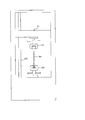
従来の強度試験機は、図12に示すような、ボールねじ500にて昇降フレーム部501を昇降させる方式が主流である(例えば、特許文献1又は特許文献2参照)。また、昇降フレーム部501を昇降させる駆動源としてモータ(図示略)が用いられている(例えば、特許文献2参照)。昇降フレーム部501には上側チャック502が設けられており、筐体の下部には下側チャック503が上側チャック502に対向して設けられている。上側チャック502と下側チャック503とで金属板試験片300の両端が把持される。
A conventional strength tester mainly uses a method of raising and lowering the
ところで、昇降フレーム部501を昇降させる駆動源としてモータを用いることで機器自体が大型化し、製品コストも高くなることから、生産現場への設置には適さない。このようなことから、本願の発明者等は生産現場での適用を可能にするため、駆動源として手動式油圧ジャッキを用いて小型で廉価な強度試験機を提案した(特許文献3参照)。以下、本願の発明者等が過去に提案した強度試験機について簡単に説明する。
By the way, using a motor as a drive source for raising and lowering the elevating
図13は、本願の発明者等が過去に提案した強度試験機200の外観を示す正面図、図14は強度試験機200の外観を示す側面図である。図13及び図14において、強度試験機200は、昇降フレーム部201を昇降させるための駆動源として、手動式の油圧ジャッキ202を有している。油圧ジャッキ202は、上部ベース203上に載置されていて、ケーシング204で覆われている。油圧ジャッキ202のラム206には、連結部材212A,212Bを介して昇降フレーム部201が接続されている。ラム206は、操作レバー213を上下動させることによって上昇し、この上昇に伴って昇降フレーム部201が上昇する。なお、操作レバー213は、油圧ジャッキ202とは別体になっており、強度試験時に油圧ジャッキ202に装着される。
FIG. 13 is a front view showing the appearance of the
上部ベース203は、4本の支柱207〜210と下部ベース板211で支持される。昇降フレーム部201の中央部下面には上側チャック215が取り付けられている。上側チャック215は、固定部材214(図14参照)にて昇降フレーム部201に取り付けられる長方形板状のつかみ歯2151と、つかみ歯2151の半分程の大きさの長方形板状で、つかみ歯2151と対向配置されるつかみ歯2152と、つかみ歯2151,2152が金属板試験片300の一端を把持するように、つかみ歯2152をつかみ歯2151側へ押し込む2本の締め付けねじ2153,2154と、を有する。つかみ歯2151,2152のそれぞれの対向面には、金属板試験片300を強固に把持できるように、波状の突起が形成されている。
The
つかみ歯2152の長手方向の両端部分には、2本の締め付けねじ2153,2154を挿通するための貫通孔(図示略)が形成されている。つかみ歯2151も同様に、その長手方向の両端部分に2本の締め付けねじ2153,2154が螺合するねじ穴(図示略)が形成されている。つかみ歯2151のねじ穴(図示略)とつかみ歯2152の貫通孔(図示略)は、2本の締め付けねじ2153,2154のそれぞれが金属板試験片300に当たらず、且つつかみ歯2151,2152を合わせたときに、それぞれの中心が一致する位置に形成されている。2本の締め付けねじ2153,2154のそれぞれを締め付けることで、つかみ歯2152がつかみ歯2151側へ押し込まれて、つかみ歯2151とともに金属板試験片300の一端を把持する。
Through holes (not shown) for inserting two
一方、下部ベース211の上面で、上側チャック215と対向する位置に下側チャック216が取り付けられている。下側チャック216は、下部ベース板211の上面に固定部材217(図14参照)にて取り付けられる長方形板状のつかみ歯2161と、つかみ歯2161の半分程の大きさの長方形板状で、つかみ歯2161と対向配置されるつかみ歯2162と、つかみ歯2161,2162が金属板試験片300の他端を把持するように、つかみ歯2162をつかみ歯2161側へ押し込む2本の締め付けねじ2163,2164と、を有する。つかみ歯2161,2162の互いに対向する面には、金属板試験片300を強固に把持できるように、波状の突起が形成されている。
On the other hand, a
つかみ歯2162の長手方向の両端部分には、2本の締め付けねじ2163,2164を挿通するための貫通孔(図示略)が形成されている。また、つかみ歯2161の長手方向の両端部分には、2本の締め付けねじ2163,2164が螺合するねじ穴(図示略)が形成されている。つかみ歯2161のねじ穴(図示略)とつかみ歯2162の貫通孔(図示略)は、2本の締め付けねじ2163,2164のそれぞれが金属板試験片300に当たらず、且つつかみ歯2161,2162を合わせたときに、それぞれの中心が一致する位置に形成されている。2本の締め付けねじ2163,2164のそれぞれを締め付けることで、つかみ歯2162がつかみ歯2161側へ押し込まれて、つかみ歯2162とともに金属板試験片300の他端を把持する。
Through holes (not shown) for inserting the two fastening
油圧ジャッキ202には、油圧計で加圧を表示するためのゲージ孔(図示略)が設けられている。このゲージ孔には、油圧を強度として該強度を電気信号に変換する圧力変換器205が装着されている。圧力変換器205には、例えば歪ゲージを用いたロードセルと呼ばれるものが用いられる。なお、ロードセルは一般的に高価であるため、必要される精度の範囲内でより安価なものを選択することも勿論可能である。強度試験機200は、圧力変換器205から出力される電気信号をデジタル表示するデジタル表示計220と、デジタル表示計220に電気的に接続されてデジタル表示計220に入力されたデータを印刷するプリンタ221も有している。
The
上側チャック215の2本の締め付けねじ2153,2154と下側チャック216の2本の締め付けねじ2163,2164のそれぞれを締め付けて金属板試験片300の両端を把持した後、油圧ジャッキ202の操作レバー213を機器本体に装着して上下動させることで、油圧ジャッキ202のラム206が上昇する。そして、ラム206の上昇に伴い、上側チャック215を連結した昇降フレーム部201が上方へ押し上げられて、金属板試験片300に引張力が与えられる。金属板試験片300は、2枚の金属板間の結合力を超える引張力が与えられることで破断する。金属試験片300が破断したときの張力が数値変換されて表示器220に表示される。引張強さは油圧ジャッキ202の油圧が圧力変換器205で電気信号となり、デジタル表示計220に「kN」の数値で表示される。金属板試験片300が破断したときのデジタル表示計220の数値は、金属板試験片300の強度の最大値である。この数値がプリンタ221で印刷されて記録として残される。
After clamping the two
なお、油圧ジャッキ202のラム206を元の位置に戻すには、油圧ジャッキ202のシリンダ(図示略)に入ったオイルを抜くためのリリーズハンドル218を開いてリリーズバルブ(図示略)を緩める。リリーズバルブ(図示略)を緩めることで油圧ジャッキ202の油圧が開放されて、ラム206に連結された昇降フレーム部201が降下する。昇降フレーム部201が降下した後、上側チャック215の2本の締め付けねじ2153,2154と下側チャック216の2本の締め付けねじ2163,2164のそれぞれを緩めて、破断した金属板試験片300を取り去ることで、強度試験が完了する。
In order to return the
しかしながら、本願の発明者等が特許文献3で提案した強度試験機200にあっては、次のような課題がある。即ち、スポット溶接で結合された2枚の金属板からなる金属板試験片300の両端を把持するための上側チャック215及び下側チャック216のそれぞれを、2本の締め付けねじ(即ち、上側チャック215にあっては締め付けねじ2153、2154、下側チャック216にあっては締め付けねじ2163,2164)で締め付ける構造としているため、これらの締め付けねじ2153,2154,2163,2164による締め付けを均等に行うことが困難であり、片締めに至るようなことがあると十分な保持力が得られなくなる。
However, the
また、この強度試験機200にあっては、4本の締め付けねじ2153,2154,2163,2164のそれぞれを締め付けることから、工数がかかり、作業性が良くない。
Further, in this
ところで、安定した保持力が得られるようにした従来の強度試験機として、例えば特開平6−148047号公報に記載されているものがある。この引張試験機は、上側チャック及び下側チャックのそれぞれをテーパ形状にして、金属板試験片を引くに従って咬合力が増す構造を採ったものであるが、上下それぞれのチャックをテーパ形状に加工するには高い精度が必要となるため、製品コストがアップしてしまうという課題がある。 Incidentally, as a conventional strength tester capable of obtaining a stable holding force, for example, there is one described in JP-A-6-148047. This tensile tester has a structure in which each of the upper chuck and the lower chuck is tapered, and the occlusal force increases as the metal plate test piece is pulled, but the upper and lower chucks are processed into a tapered shape. Has a problem that the product cost increases because high accuracy is required.
本発明は、上述した従来の課題を解決するために、スポット溶接で結合された2枚の金属板からなる金属板試験片を把持するための上下2つのチャックのそれぞれにおいて、比較的簡単な構造で金属板試験片を容易にかつ均等に締め付けることができる強度試験機を提供することを目的とする。 In order to solve the above-described conventional problems, the present invention has a relatively simple structure in each of two upper and lower chucks for holding a metal plate test piece composed of two metal plates joined by spot welding. An object of the present invention is to provide a strength tester capable of easily and evenly clamping a metal plate test piece.
本発明の強度試験機は、筐体フレームの上部ベース板上に載置された手動式の油圧ジャッキと、前記筐体フレーム内で、前記油圧ジャッキの下方に配置され、スポット溶接された金属板試験片の一端を把持する上側チャックと、前記筐体フレーム内で、前記上側チャックの下方に離間して対向配置され、前記金属板試験片の他端を把持する下側チャックと、を備えた強度試験機であって、前記上側チャックは、方形板状を成し、一方向の上端部側が前記油圧ジャッキ側に接続され、前記一方向の下端部側には、中心から左右に同一距離離れた2つの位置の一方に板厚方向の両面を貫通する第1のねじ孔が形成され、前記2つの位置の他方に板厚方向の両面を貫通する第2のねじ孔が形成され、前記油圧ジャッキのラムの上昇によって前記油圧ジャッキ側に引っ張られる第1のつかみ歯と、方形板状を成し、前記第1のつかみ歯の前記一方向の下端部側に対向して配置され、中央に板厚方向の両面を貫通する第3のねじ孔が形成され、軸心が前記第1のつかみ歯の前記第1のねじ孔の軸心と一致する位置に二段階の異なる孔径の第1の貫通孔が形成され、軸心が前記第1のつかみ歯の前記第2のねじ孔の軸心と一致する位置に二段階の異なる孔径の第2の貫通孔が形成された第1の押圧板と、方形板状を成し、前記第1のつかみ歯と前記第1の押圧板との間に配置され、軸心が前記第1のつかみ歯の前記第1のねじ孔及び前記第1の押圧板の前記第1の貫通孔それぞれの軸心と一致する位置に板厚方向の両面を貫通する第5の貫通孔が形成され、軸心が前記第1のつかみ歯の前記第2のねじ孔及び前記第1の押圧板の前記第2の貫通孔それぞれの軸心と一致する位置に板厚方向の両面を貫通する第6の貫通孔が形成された第2のつかみ歯と、軸方向の長さが前記第2のつかみ歯の板厚より長い筒状を成し、前記第2のつかみ歯の前記第5の貫通孔に挿入される第1のスペーサと、軸方向の長さが前記第2のつかみ歯の板厚より長い筒状を成し、前記第2のつかみ歯の前記第6の貫通孔に挿入される第2のスペーサと、前記第1の押圧板の第1の貫通孔と前記第2のつかみ歯の前記第5の貫通孔に挿入された前記第1のスペーサを通して前記第1のつかみ歯の第1のねじ孔と螺合する第1の連結ボルトと、前記第1の押圧板の第2の貫通孔と前記第2のつかみ歯の前記第6の貫通孔に挿入された前記第2のスペーサを通して前記第1のつかみ歯の第2のねじ孔と螺合する第2の連結ボルトと、ねじの長さが前記第1の押圧板の板厚より長く、前記第1の押圧板の前記第3のねじ孔と螺合する第1の締め付けねじと、を備え、前記下側チャックは、方形板状を成し、一方向の下端部側が前記筐体フレームの下部ベース板に接続され、前記一方向の上端部側には、中心から左右に同一距離離れた2つの位置の一方に板厚方向の両面を貫通する第6のねじ孔が形成され、前記2つの位置の他方に板厚方向の両面を貫通する第7のねじ孔が形成され第3のつかみ歯と、方形板状を成し、前記第3のつかみ歯の前記一方向の上端部側に対向して配置され、中央に板厚方向の両面を貫通する第8のねじ孔が形成され、軸心が前記第3のつかみ歯の前記第6のねじ孔の軸心と一致する位置に二段階の異なる孔径の第7の貫通孔が形成され、軸心が前記第3のつかみ歯の前記第7のねじ孔の軸心と一致する位置に二段階の異なる孔径の第8の貫通孔が形成された第2の押圧板と、方形板状を成し、前記第3のつかみ歯と前記第2の押圧板との間に配置され、軸心が前記第3のつかみ歯の前記第6のねじ孔及び前記第2の押圧板の前記第7の貫通孔それぞれの軸心と一致する位置に板厚方向の両面を貫通する第11の貫通孔が形成され、軸心が前記第3のつかみ歯の前記第7のねじ孔及び前記第2の押圧板の前記第8の貫通孔それぞれの軸心と一致する位置に板厚方向の両面を貫通する第12の貫通孔が形成された第4のつかみ歯と、軸方向の長さが前記第4のつかみ歯の板厚より長い筒状を成し、前記第4のつかみ歯の前記第11の貫通孔に挿入される第3のスペーサと、軸方向の長さが前記第4のつかみ歯の板厚より長い筒状を成し、前記第4のつかみ歯の前記第12の貫通孔に挿入される第4のスペーサと、前記第2の押圧板の第7の貫通孔と前記第4のつかみ歯の前記第11の貫通孔に挿入された前記第3のスペーサを通して前記第3のつかみ歯の第6のねじ孔と螺合する第3の連結ボルトと、前記第2の押圧板の第7の貫通孔と前記第4のつかみ歯の前記第12の貫通孔に挿入された前記第4のスペーサを通して前記第3のつかみ歯の第7のねじ孔と螺合する第4の連結ボルトと、ねじの長さが前記第2の押圧板の厚みよりも長く、前記第2の押圧板の前記第8のねじ孔と螺合する第2の締め付けねじと、を備える。 The strength tester according to the present invention includes a manual hydraulic jack placed on an upper base plate of a housing frame, and a spot-welded metal plate disposed below the hydraulic jack in the housing frame. An upper chuck for gripping one end of the test piece, and a lower chuck that is disposed opposite to and spaced below the upper chuck in the housing frame and grips the other end of the metal plate test piece. In the strength tester, the upper chuck has a rectangular plate shape, and an upper end portion in one direction is connected to the hydraulic jack side, and the lower end portion in the one direction is separated by the same distance from the center to the left and right. A first screw hole penetrating both surfaces in the plate thickness direction is formed in one of the two positions, and a second screw hole penetrating both surfaces in the plate thickness direction is formed in the other of the two positions. Said hydraulic by raising the jack ram It forms a square plate shape with the first gripping tooth pulled to the jack side, and is disposed to face the lower end side in the one direction of the first gripping tooth, and penetrates both sides in the plate thickness direction at the center. A third screw hole is formed, and a first through-hole having two different diameters is formed at a position where the axis coincides with the axis of the first screw hole of the first gripping tooth. And a first pressing plate in which a second through hole having two different diameters is formed at a position coinciding with the axis of the second screw hole of the first gripping tooth, and a rectangular plate shape. The first gripping tooth and the first pressing plate are disposed between the first screw hole and the first pressing plate and the first penetration hole of the first pressing plate. A fifth through hole penetrating both surfaces in the plate thickness direction is formed at a position coinciding with the axial center of each hole, and the axial center is the second of the first gripping teeth. A second gripping tooth in which a sixth through-hole penetrating both surfaces in the plate thickness direction is formed at a position coinciding with the axial center of each of the second through-holes of the screw hole and the first pressing plate; A first spacer inserted in the fifth through-hole of the second gripping tooth in a cylindrical shape whose length in the direction is longer than the plate thickness of the second gripping tooth, and an axial length Has a cylindrical shape longer than the plate thickness of the second gripping tooth, and a second spacer inserted into the sixth through-hole of the second gripping tooth, and a first of the first pressing plate A first connecting bolt that engages with the first screw hole of the first gripping tooth through the first spacer inserted into the fifth through hole of the second gripping tooth, Through the second spacer inserted into the second through hole of the first pressing plate and the sixth through hole of the second gripping tooth, the A second connecting bolt that is screwed into the second screw hole of the first gripping tooth, and the length of the screw is longer than the thickness of the first pressing plate; A first clamping screw that engages with a screw hole, and the lower chuck has a rectangular plate shape, and a lower end portion in one direction is connected to a lower base plate of the housing frame, and the one direction A sixth screw hole penetrating both sides in the plate thickness direction is formed in one of two positions that are the same distance from the center on the left and right sides, and both sides in the plate thickness direction are formed at the other of the two positions. A seventh screw hole penetrating the third gripping tooth is formed to form a rectangular plate shape, and is disposed opposite to the upper end portion in the one direction of the third gripping tooth, with a plate thickness at the center. An eighth screw hole penetrating both sides of the direction is formed, and the axis coincides with the axis of the sixth screw hole of the third gripping tooth A seventh through-hole having two different hole diameters is formed in the position, and the eighth center of the two different hole diameters is located at a position where the axis coincides with the axis of the seventh screw hole of the third gripping tooth. The second pressing plate having a through hole and a square plate shape are disposed between the third gripping tooth and the second pressing plate, and an axis is formed of the third gripping tooth. An eleventh through hole penetrating both surfaces in the plate thickness direction is formed at a position coinciding with the respective axial centers of the sixth screw hole and the seventh through hole of the second pressing plate, and the axial center is the A twelfth through hole penetrating both surfaces in the plate thickness direction is formed at a position coinciding with the axis of each of the seventh screw hole of the third gripping tooth and the eighth through hole of the second pressing plate. A fourth gripping tooth having a cylindrical shape whose axial length is longer than the plate thickness of the fourth gripping tooth, and A third spacer inserted into one through-hole, and a cylindrical shape whose axial length is longer than the plate thickness of the fourth gripping tooth, and the twelfth through-hole of the fourth gripping tooth The third spacer inserted into the seventh spacer inserted into the eleventh through hole of the fourth spacer inserted into the seventh through hole of the second pressing plate and the fourth gripping tooth. The third connecting bolt screwed into the sixth screw hole of the gripping tooth, the seventh through hole of the second pressing plate, and the twelfth through hole of the fourth gripping tooth A fourth connecting bolt threadedly engaged with a seventh screw hole of the third gripping tooth through a fourth spacer; and a screw length longer than a thickness of the second pressing plate; A second clamping screw that is screwed into the eighth screw hole of the plate .
上記構成によれば、上側チャックと下側チャックは、それぞれ、2つのつかみ歯と、1つの押圧板と、これらを連結する2個のスペーサ及び2本の連結ボルトと、押圧板を介して一方のつかみ歯を他方のつかみ歯側へ押し込む1本の締め付けねじと、を有し、上側チャックと下側チャックのそれぞれにおいて1本の締め付けねじで2つのつかみ歯の締め付けを行うので、上側チャックと下側チャックのそれぞれにおいて片締めに至るようなことがない。このように、比較的簡単な構造で金属板試験片を容易にかつ均等に締め付けることができる。 According to the above configuration, each of the upper chuck and the lower chuck has two gripping teeth, one pressing plate, two spacers and two connecting bolts for connecting them, and one via the pressing plate. One clamping screw that pushes the gripping tooth into the other gripping tooth side, and tightens the two gripping teeth with one clamping screw in each of the upper chuck and the lower chuck. Each of the lower chucks does not reach one-side tightening. In this way, the metal plate test piece can be easily and evenly clamped with a relatively simple structure.
上記構成において、前記上側チャックにおいて、前記第1の押圧板には、前記第1,第2の貫通孔より中心側で、中心から左右同一距離離れた2つの位置の一方に板厚方向の両面を貫通する二段階の異なる孔径を有する第3の貫通孔が形成され、前記2つの位置の他方に板厚方向の両面を貫通する二段階の異なる孔径を有する第4の貫通孔が形成され、前記第2のつかみ歯には、前記第1の押圧板の前記第3の貫通孔の軸心と一致する位置に板厚方向に延びる第4のねじ孔が形成され、前記第1の押圧板の前記第4の貫通孔の軸心と一致する位置に板厚方向に延びる第5のねじ孔が形成される一方、前記第1の押圧板の前記第3の貫通孔の小径部分より径が大きい第1のスプリングと、前記第1の押圧板の前記第4の貫通孔の小径部分より径が大きい第2のスプリングと、ねじが切られた小径の先端部分とその他の大径部分とからなる二段階の異なる外径を有し、前記大径部分に前記第1のスプリングが挿入された状態で、前記第1の押圧板の前記第3の貫通孔に挿入されて前記小径の先端部分が前記第2のつかみ歯の前記第4のねじ孔に螺合する第1の付勢力調整ねじと、ねじが切られた小径の先端部分とその他の大径部分とからなる二段階の異なる外径を有し、前記大径部分に前記第2のスプリングが挿入された状態で、前記第1の押圧板の前記第4の貫通孔に挿入されて前記小径の先端部分が前記第2のつかみ歯の前記第5のねじ孔に螺合する第2の付勢力調整ねじと、を更に備え、前記第1,第2の付勢力調整ねじと前記第1,第2のスプリングは、前記第2のつかみ歯を前記第1の押圧板側に付勢する付勢手段として作用し、前記下側チャックにおいて、前記第2の押圧板には、前記第7,第8の貫通孔より中心側で、中心から左右同一距離離れた2つの位置の一方に板厚方向の両面を貫通する二段階の異なる孔径を有する第9の貫通孔が形成され、前記2つの位置の他方に板厚方向の両面を貫通する二段階の異なる孔径を有する第10の貫通孔が形成され、前記第4のつかみ歯には、前記第2の押圧板の前記第9の貫通孔の軸心と一致する位置に板厚方向に延びる第9のねじ孔が形成され、前記第2の押圧板の前記第10の貫通孔の軸心と一致する位置に板厚方向に延びる第10のねじ孔が形成される一方、前記第2の押圧板の前記第9の貫通孔の小径部分より径が大きい第3のスプリングと、前記第2の押圧板の前記第10の貫通孔の小径部分より径が大きい第4のスプリングと、ねじが切られた小径の先端部分とその他の大径部分とからなる二段階の異なる外径を有し、前記大径部分に前記第3のスプリングが挿入された状態で、前記第2の押圧板の第9の貫通孔に挿入されて前記小径の先端部分が前記第4のつかみ歯の前記第9のねじ孔に螺合する第3の付勢力調整ねじと、ねじが切られた小径の先端部分とその他の大径部分とからなる二段階の異なる外径を有し、前記大径部分に前記第4のスプリングが挿入された状態で、前記第2の押圧板の第10の貫通孔に挿入されて前記小径の先端部分が前記第4のつかみ歯の前記第10のねじ孔に螺合する第4の付勢力調整ねじと、を更に備え、前記第3,第4の付勢力調整ねじと前記第3,第4のスプリングは、前記第4のつかみ歯を前記第2の押圧板側に付勢する付勢手段として作用する。 In the above configuration, in the upper chuck, the first pressing plate is located on both sides in the plate thickness direction at one of two positions on the center side with respect to the first and second through holes and at the same distance from the center. A third through hole having two different hole diameters penetrating through the second through hole is formed, and a fourth through hole having two different hole diameters penetrating both surfaces in the thickness direction is formed at the other of the two positions. A fourth screw hole extending in the thickness direction is formed in the second gripping tooth at a position coinciding with the axis of the third through hole of the first pressing plate, and the first pressing plate A fifth screw hole extending in the plate thickness direction is formed at a position coinciding with the axis of the fourth through hole of the fourth through hole, and the diameter is smaller than the small diameter portion of the third through hole of the first pressing plate. A larger first spring and a diameter smaller than a small diameter portion of the fourth through hole of the first pressing plate A state in which the first spring is inserted into the large-diameter portion having two different outer diameters consisting of a large second spring, a threaded small-diameter tip portion, and another large-diameter portion. And a first urging force adjusting screw inserted into the third through hole of the first pressing plate and the small-diameter tip portion screwed into the fourth screw hole of the second gripping tooth. , Having a two-stage different outer diameter consisting of a threaded small diameter tip portion and another large diameter portion, with the second spring inserted into the large diameter portion, A second urging force adjusting screw that is inserted into the fourth through hole of the pressing plate and in which the tip portion of the small diameter is screwed into the fifth screw hole of the second gripping tooth, The first and second urging force adjusting screws and the first and second springs are arranged with the second gripping teeth. It acts as a biasing means for biasing toward the first pressing plate side, and in the lower chuck, the second pressing plate has a center side from the seventh and eighth through holes and a right and left side from the center. A ninth through hole having two different diameters penetrating both sides in the plate thickness direction is formed at one of two positions separated by the same distance, and the other of the two positions passes through both sides in the plate thickness direction. A tenth through hole having a different diameter is formed, and the fourth gripping tooth extends in the thickness direction at a position coincident with the axis of the ninth through hole of the second pressing plate. A ninth screw hole is formed, and a tenth screw hole extending in the plate thickness direction is formed at a position coinciding with the axis of the tenth through hole of the second pressing plate, while the second screw plate A third spring having a larger diameter than the small diameter portion of the ninth through hole of the pressing plate, and the second pressing A fourth spring having a diameter larger than the small diameter portion of the tenth through-hole of the plate, a small-diameter tip portion that is threaded, and another large-diameter portion; With the third spring inserted into the large diameter portion, the ninth screw of the fourth gripping tooth is inserted into the ninth through hole of the second pressing plate, and the small diameter tip portion is the fourth gripping tooth. The third urging force adjusting screw that is screwed into the hole, a small-diameter tip portion that is threaded, and another large-diameter portion have two different outer diameters. In the state in which the spring is inserted, a fourth end is inserted into the tenth through hole of the second pressing plate and the small diameter tip portion is screwed into the tenth screw hole of the fourth gripping tooth. And the third and fourth biasing force adjusting screws and the third and fourth biasing force adjusting screws. Pulling acts as a biasing means for biasing said fourth gripping teeth on the second pressing plate side.
上記構成によれば、上側チャックにおいては、第1の締め付けねじを緩めるに従って第2のつかみ歯が第1のつかみ歯から離れて行くので、上側チャックにおける金属板試験片の着脱を容易に且つ短時間で行うことができる。下側チャックにおいても同様に、第2の締め付けねじを緩めるに従って第4のつかみ歯が第3のつかみ歯から離れて行くので、下側チャックにおける金属板試験片の着脱を容易に且つ短時間で行うことができる。 According to the above configuration, in the upper chuck, as the first clamping screw is loosened, the second gripping tooth moves away from the first gripping tooth. Can be done in time. Similarly, in the lower chuck, as the second clamping screw is loosened, the fourth gripping tooth moves away from the third gripping tooth, so that the metal plate test piece can be easily attached and detached from the lower chuck in a short time. It can be carried out.
本発明によれば、スポット溶接で結合された例えば金属板からなる金属板試験片を把持するための上下2つのチャックのそれぞれにおいて、比較的簡単な構造で金属板試験片を容易にかつ均等に締め付けることができる。 According to the present invention, in each of the upper and lower chucks for holding a metal plate test piece made of, for example, a metal plate joined by spot welding, the metal plate test piece can be easily and evenly provided with a relatively simple structure. Can be tightened.
以下、本発明を実施するための好適な実施形態について、図面を参照して詳細に説明する。 DESCRIPTION OF EXEMPLARY EMBODIMENTS Hereinafter, preferred embodiments for carrying out the invention will be described in detail with reference to the drawings.
図1は、本発明の一実施形態に係る強度試験機1の外観を示し、(a)は正面図、(b)は右側面図である。図2は、強度試験機1の上側チャック3及び下側チャック4が設けられた部分を拡大した正面図である。また、図3は、強度試験機1の上側チャック3及び下側チャック4が設けられた部分を拡大した右側面図である。なお、図1〜図3において、前述した図13及び図14と共通する部分には同一の符号を付けている。また、本実施形態に係る強度試験機1は、これを構成する部材の殆どが金属製であり、特に断らない限り金属製である旨の記載は行わないものとする。
FIG. 1 shows an appearance of a
図1〜図3において、強度試験機1の上側チャック3は、スポット溶接された2枚の金属板からなる金属板試験片300の一端を把持し、下側チャック4は、金属板試験片300の他端を把持する。上側チャック3は、昇降フレーム部201の中央部下面に取り付けられる。下側チャック4は、4本のフレーム207〜210の下側に設けられた下部ベース板211の上面で、上側チャック3と対向する位置に取り付けられる。昇降フレーム部201は、図13及び図14に示す従来の強度試験機200と同様に、ケーシング204に収容された油圧ジャッキ202のラム206に連結部材212A,212Bを介して接続される。油圧ジャッキ202のラム206は、油圧ジャッキ202の操作レバー213が装着されて上下動されることで上昇し、この上昇に伴って昇降フレーム部201が上昇する。油圧ジャッキ202のラム206が上昇した後、油圧ジャッキ202のシリーズハンドル218を開いてプリーズバルブ(図示略)を緩めることで、ラム206が元の位置まで徐々に降下し、元の位置に戻る。なお、ラム206を元の位置まで降下させた後、再度試験を行う場合は、シリーズハンドル218を締めてシリーズバルブ(図示略)を閉じてから行う。
In FIG. 1 to FIG. 3, the
上側チャック3は、固定部材214にて昇降フレーム部201に取り付けられる長方形板状の第1のつかみ歯31と、中央部の両面を貫通するねじ孔が形成された長方形板状の第1の押圧板32と、第1のつかみ歯31と第1の押圧板32が厚さ方向に離間して並行配置するように、第1のつかみ歯31の両端部の一方と第1の押圧板32の両端部の一方を連結する第1の連結ボルト33と、第1のつかみ歯31の両端部の他方と第1の押圧板32の両端部の他方を連結する第2の連結ボルト34と、第1のつかみ歯31と略同形の長方形板状をなし、両端部の一方には第1の連結ボルト33を挿通可能な貫通孔(第5の貫通孔、図示略)が形成され、両端部の他方には第2の連結ボルト34を挿通可能な貫通孔(第6の貫通孔、図示略)が形成され、第1のつかみ歯31と第1の押圧板32との間に配置される第2のつかみ歯35と、第1の押圧板32の中央部に形成されたねじ孔(第3のねじ孔、図示略)に螺合する第1の締め付けねじ36と、を有する。第1,第2のつかみ歯31,35の互いに対向する面には、金属板試験片300を強固に把持できるように、波状の突起が形成されている。なお、第1、第2のつかみ歯31,35及び第1の押圧板32それぞれの外形を長方形状としたが、正方形状であっても構わない。
The
第1のつかみ歯31に形成された2つの貫通孔(第1,第2のねじ孔、図示略)には、第1,第2の連結ボルト33,34のそれぞれに形成されたねじと螺合するねじが形成されている。第1の押圧板32に形成された2つの貫通孔(第1,第2の貫通孔、図示略)は、第1,第2の連結ボルト33,34の円筒部を通過させる部分と、第1,第2の連結ボルト33,34の頭部を収容する部分の2つの異径部分とからなる。第1の押圧板32に形成された2つの貫通孔(第1,第2の貫通孔、図示略)における、第1,第2の連結ボルト33,34の円筒部が通過する部分には、ねじは形成されていない。
Two through-holes ( first and second screw holes, not shown) formed in the first
また、上側チャック3は、第1の締め付けねじ36の取り付け位置の両側に等間隔で配置される第1,第2の付勢部材37,38を有する。第1の付勢部材37は、第1の押圧板32の第1の連結ボルト33より内側に配置される。第2の付勢部材38は、第1の押圧板32の第2の連結ボルト34より内側に配置される。第1,第2の付勢部材37,38は、第2のつかみ歯35を常時第1の押圧板32側へ付勢するものである。第1,第2の付勢部材37,38の詳細については後述する。
The
図4は、図2における上側チャック3のA−A線断面図である。同図に示すように、第1,第2のつかみ歯31,35と第1の押圧板32が第1,第2の連結ボルト33,34によって連結される。第1の連結ボルト33が配置される箇所の第1のつかみ歯31と第1の押圧板32との間には第1のスペーサ50Aが配置され、第2の連結ボルト34が配置される箇所の第1のつかみ歯31と第1の押圧板32との間には第2のスペーサ50Bが配置される。第1のスペーサ50Aは、両端が開口した円筒形状をなし、その内径が第1の連結ボルト33の外径より僅かに大きく、内面が平坦になっている。また、図示のように、第1のスペーサ50Aの軸心方向の長さが第2のつかみ歯35の板厚よりも長くなっている。第2のスペーサ50Bも第1のスペーサ50Aと同様に、両端が開口した円筒形状をなし、その内径が第2の連結ボルト34の外径より僅かに大きく、内面が平坦になっている。また、図示のように、第2のスペーサ50Bの軸心方向の長さが第2のつかみ歯35の板厚よりも長くなっている。第1,第2のスペーサ50A,50Bを介して第1,第2のつかみ歯31,35と第1の押圧板32が第1,第2の連結ボルト33,34によって連結される。
FIG. 4 is a cross-sectional view of the
第2のつかみ歯35の両端部の一方に第1のスペーサ50Aを挿通可能な貫通孔(第5の貫通孔、図示略)が形成されており、他方に第2のスペーサ50Bを挿通可能な貫通孔(第6の貫通孔、図示略)が形成されている。第2のつかみ歯35は、第1,第2のスペーサ50A,50Bによって、第1のつかみ歯31と第1の押圧板32の間での移動が可能になっている。なお、第1,第2のスペーサ50A,50Bそれぞれの形状は円筒形状に限定されるものではない。要は、第2のつかみ歯35を移動自在に支持できて、第1,第2の連結ボルト33,34を通すことができれば、どのような形状であってもよい。例えば、両端が開口した断面六角形状であってもよい。
A through hole ( fifth through hole, not shown) through which the
第1,第2の付勢部材37,38は、それぞれ、ねじ(第1の付勢力調整ねじ)55及びスプリング(ばね)56で構成される。ねじ55は、その円筒部55aの径がねじ部55bの径より大きくなった異径のねじである。ねじ55は、スプリング(第1のスプリング)56とともに第1の押圧板32に形成された貫通孔(第3の貫通孔)32aに収容される。ねじ55のねじ部55bは、第2のつかみ歯35に形成されたねじ孔(第4のねじ孔)と螺合するように形成されている。第1の押圧板32の貫通孔32aは、第1の付勢部材(付勢手段)37が挿入される側の開口がスプリング56の径より若干大きく、第2のつかみ歯35に面する側の開口がねじ55のねじ部55bの径よりも若干大きくなるように形成されている。第1の押圧板32の貫通孔(第4の貫通孔)32bは、第2の付勢部材(付勢手段)38が挿入される側の開口がスプリング(第2のスプリング)56の径より若干大きく、第2のつかみ歯35に面する側の開口がねじ(第2の付勢力調整ねじ)55のねじ部55bの径よりも若干大きくなるように形成されている。第1の押圧板32の貫通孔32a,32bの第2のつかみ歯35に面する側の開口径を、第1,第2の付勢部材37,38を挿入する側の開口径よりも小さく形成することで、スプリング56の貫通孔32a,32bからの抜けを防止している。
The first and
第2のつかみ歯35が第1の押圧板32に接触している状態で、第1の付勢部材37のねじ55を第1の押圧板32の貫通孔32a内に挿入してねじ込むことで、第1の付勢部材37が第2のつかみ歯35に固定される。同様にして、第2の付勢部材38のねじ55を第1の押圧板32の貫通孔32b内に挿入してねじ込むことで、第2の付勢部材38が第2のつかみ歯35に固定される。第1,第2の付勢部材37,38は、第2のつかみ歯35が第1の押圧板32に接触している状態で、多少の付勢力が第2のつかみ歯35にかかるように形成されている。このように、第2のつかみ歯35は、第1,第2の付勢部材37,38によって、常時第1の押圧板32側に付勢される。第2のつかみ歯35は、第1の締め付けねじ36が締め付けられていないときは第1の押圧板32に接触しているが、第1の締め付けねじ36が締め付けられるに従い、徐々に第1の押圧板32から離れて第1のつかみ歯31に近づいて行く。
By inserting the
上側チャック3の第1,第2のつかみ歯31,35間には金属板試験片300の一端が挿入されるので、第1の締め付けねじ36の締め付けにより、第1,第2のつかみ歯31,35にて金属板試験片300の一端が把持される。なお、第1の締め付けねじ36を締める際には、図1又は図2に示すドライバ240が用いられる。
Since one end of the metal
図5は、図2に示す上側チャック3のA−A線断面図であり、第1の締め付けねじ36を締め付けていないとき(図面に向かって左側の状態)と、締め付けたとき(図面に向かって右側の状態)の第2のつかみ歯35の位置と第1,第2の付勢部材37,38のスプリング56の収縮度合いの違いを示す図である。同図に示すように、第1の締め付けねじ36が締め付けられていないときは、第1,第2の付勢部材37,38それぞれのスプリング56が伸びきる手前の状態にあり、それぞれの僅かな付勢力によって第2のつかみ歯35が第1の押圧板32側に引き付けられている。この状態から第1の締め付けねじ36を締め付けることで、第1の締め付けねじ36が第1のつかみ歯31側へ進行し、第2のつかみ歯35に当接すると、そめ時点から第2のつかみ歯35を第1のつかみ歯31側へ押し出して行く。
FIG. 5 is a cross-sectional view of the
第2のつかみ歯35が第1のつかみ歯31側へ移動して行くことで、第1,第2の付勢部材37,38それぞれのスプリング56が縮んでいき、第2のつかみ歯35を第1の押圧板32側へ戻すための復元力が増して行く。第1の締め付けねじ36の締め付けは、第1,第2つかみ歯31,35間に挿入された金属板試験片300の一端を強固に保持するまで行われる。金属板試験片300の一端を把持した後、第1締め付けねじ36を緩めると、それに従い、第2のつかみ歯35が第1,第2の付勢部材37,38の付勢力によって第1の押圧板32側へ引き戻されて行く。そして、最終的に第1の押圧板32に接触する。
As the second
このように、上側チャック3は、1本の第1の締め付けねじ36で第1,第2のつかみ歯31,35の締め付けを行う構造を有するので、金属板試験片300を把持する際に片締めに至ることがなく、十分な保持力で把持することが可能となる。また、上側チャック3は、第1,第2の付勢部材37,38を有し、これらによって、常時、第2のつかみ歯35を第1の押圧板32側へ付勢するので、上側チャック3における金属板試験片300の着脱を容易に且つ短時間で行うことが可能となる。
As described above, the
一方、下側チャック4は、上側チャック3に対し、垂直方向に離間して対向配置され、金属板試験片300の他端を把持する。図2及び図3において、下側チャック4は、上側チャック3と同様の構成の有する。即ち、下側チャック4は、4本の筐体フレーム207〜210の下側に設けられた下部ベース板211上に固定される長方形板状の第3のつかみ歯41と、中央部の両面を貫通するねじ孔が形成された長方形板状の第2の押圧板42と、第3のつかみ歯41の両端部の一方と第2の押圧板42の両端部の一方との間に介挿される円筒形状の第3のスペーサ(図示略)と、第3のつかみ歯41の両端部の他方と第2の押圧板42の両端部の他方との間に介挿される円筒形状の第4のスペーサ(図示略)と、第3のスペーサ(図示略)を通して第3のつかみ歯41の両端部の一方と第2の押圧板42の両端部の一方を連結する第3の連結ボルト43と、第4のスペーサ(図示略)を通して第3のつかみ歯41の両端部の他方と第2の押圧板42の両端部の他方を連結する第4の連結ボルト44と、長方形板状をなし、両端部の一方に第3の連結ボルト43が螺合するねじ孔(第6のねじ孔、図示略)が形成され、両端部の他方に第4の連結ボルト44が螺合するねじ孔(第7のねじ孔、図示略)が形成された第3のつかみ歯41と、第3のつかみ歯41と第2の押圧板42との間に配置される第4のつかみ歯45と、第2の押圧板42の中央部に形成されたねじ孔(第8のねじ孔)に螺合する第2の締め付けねじ46と、を有する。なお、上記第3、第4のスペーサは、上側チャック3の第1、第2のスペーサ50A,50Bと同様のものである。
On the other hand, the lower chuck 4 is opposed to the
第3のつかみ歯41に形成された2つの貫通孔(第6,第7のねじ孔)には、第3,第4の連結ボルト43,44のねじ部と螺合するねじが形成されている。第2の押圧板42に形成された2つの貫通孔(第7の貫通孔、第8の貫通孔、図示略)は、第3,第4の連結ボルト43,44の円筒部を通過させる部分と、第3,第4の連結ボルト43,44の頭部を収容する部分の2つの異径部分からなる。第2の押圧板42の2つの貫通孔(第7の貫通孔、第8の貫通孔)には、ねじは形成されていない。第4のつかみ歯45の両端部の一方に第3のスペーサを挿通可能な貫通孔(第11の貫通孔、図示略)が形成されており、他方に第4のスペーサを挿通可能な貫通孔(第12の貫通孔、図示略)が形成されている。第4のつかみ歯45は、第3,第4のスペーサ(図示略)によって、第3のつかみ歯41と第2の押圧板42の間での移動が可能になっている。
The two through holes (sixth and seventh screw holes) formed in the third
また、下側チャック4は、第2の締め付けねじ46の取り付け位置の両側に等間隔で配置され、第4のつかみ歯45を第2の押圧板42側へ付勢する第3,第4の付勢部材47,48を有する。第3の付勢部材47は、第3の連結ボルト43の内側に配置され、第4の付勢部材48は、第4の連結ボルト44の内側に配置される。なお、図示しないが、第4のつかみ歯45には、第3,第4の付勢部材47,48を構成するねじが螺合するねじ孔が形成されている。この場合、第3の付勢部材47を構成するねじが螺合するねじ孔が第9のねじ孔に対応し、第4の付勢部材48を構成するねじが螺合するねじ孔が第10のねじ孔に対応する。また、第3の付勢部材47を構成するねじが第3の付勢力調整ねじに対応し、第4の付勢部材48を構成するねじが第4の付勢力調整ねじに対応する。また、第3,第4の付勢部材47,48は、それぞれ付勢手段に対応する。
The lower chuck 4 is arranged at equal intervals on both sides of the mounting position of the second tightening
下側チャック4は、上側チャック3と同一の構成であるので、詳細な説明は省略する。また、図2における下側チャック4のB−B線断面図は、上側チャック3のA−A線断面と同様の図になるため、下側チャック4の断面図については省略する。
Since the lower chuck 4 has the same configuration as that of the
このように、下側チャック4においても1本の第2の締め付けねじ46で第3,第4のっかみ歯41,45の締め付けを行う構造を有するので、金属板試験片300を把持する際に片締めに至ることがなく、十分な保持力で把持することが可能となる。また、下側チャック4も第3,第4の付勢部材47,48を有し、これらによって、常時、第4のつかみ歯45を第2の押圧板42側へ付勢するので、下側チャック4における金属板試験片300の着脱を容易に且つ短時間で行うことが可能となる。
As described above, the lower chuck 4 also has a structure in which the third and fourth biting
また、下側チャック4は、下部ベース板211上において、金属板試験片300の厚さ方向に対し前後移動が可能な構造を有している。図6は、下側チャック4の構造を示す断面図である。同図において、下側チャック4は、それぞれが断面L字状に形成された2個の固定金具225a、225bと、これらの固定金具225a、225bに第3のつかみ歯41を固定するためのボルト226及びナット227と、下部ベース板211の裏面側に配置され、固定金具225a,225bを下部ベース板211に固定するための当て板228と、固定金具225a、225bを当て板228及び4個のスペーサ230とともに下部ベース板211に固定するための4本のボルト229と、を有する。なお、図6の断面図では4本のボルト229のうち2本しか見えてないが、実際は4本ある。また、スペーサ230も4本のボルト229それぞれに対して設けられるので、実際は4個ある。
The lower chuck 4 has a structure that can move back and forth in the thickness direction of the metal
下部ベース板211には、金属板試験片300の厚さ方向(矢印C方向)に延びる楕円状(図では楕円状には見えないが、実際はそのようになっている)の貫通孔211aが4個形成されている。4個の楕円状の貫通孔211aは、それぞれの中央が固定金具225a,225bのボルト229を通す貫通孔と一致する位置に形成されている。当て板228には4本のボルト229と螺合する4個のねじ孔(図示略)が形成されている。下部ベース板211に形成された4個の貫通孔211aのそれぞれに円筒形のスペーサ230を介在させてボルト229を通し、各ボルト229を当て板228に形成されたねじ孔に螺合させることで、下側チャック4が金属板試験片300の厚さ方向(矢印C方向)に移動可能に固定される。4本のボルト229は、下側チャック4を比較的小さな力で動かすことができる程度で締め付けられる。
The
下側チャック4は、通常、その軸心が上側チャック3の上下方向の軸心と一致するように位置決めされるが、金属板試験片300を構成する2枚の金属板のそれぞれの厚みが増すと、軸心にずれが生じて金属板試験片300に反りが生じることになる。金属板試験片300に反りが生じると、垂直応力以外にせん断応力が生じ、これが原因で強度試験での精度が低下してしまう。これに対し、下側チャック4を金属板試験片300の厚さ方向に対して前後移動可能な構造を採ることで、金属板試験片300を構成する2枚の金属板のそれぞれの厚みが増しても、金属板試験片300を引っ張ったときに、2枚の金属板のそれぞれの厚みが増した分だけ下側チャック4が矢印C方向へ移動するので、軸心のずれが修正されて金属板試験片300に反りが生じなくなる。これにより、常に高い精度で強度試験を行うことが可能となる。
The lower chuck 4 is usually positioned so that its axis coincides with the vertical axis of the
このように、本実施形態に係る強度試験機1によれば、上側チャック3は、第1,第2のつかみ歯31,35と、第1の押圧板32と、これらを連結する2個のスペーサ50A,50B及び第1,第2の連結ボルト33,34と、第1の押圧板32を介して第2のつかみ歯35を第1のつかみ歯31側へ押し込む第1の締め付けねじ36と、を有し、下側チャック4は、第3,第4のつかみ歯41,45と、第2の押圧板42と、これらを連結する2個のスペーサ(図示略)及び第3,第4の連結ボルト43,44と、第2の押圧板42を介して第4のつかみ歯45を第3のつかみ歯41側へ押し込む第2の締め付けねじ46と、を有し、上側チャック3においてはつかみ歯31,35の締め付けを行い、下側チャック4においてはつかみ歯41,45の締め付けを行うので、上側チャック3と下側チャック4のそれぞれにおいて片締めに至ることがなく、比較的簡単な構造で金属板試験片300を容易にかつ均等に締め付けることが可能となる。また、締め付けねじの部品点数が少なくなる分、コストダウン及び作業工数の削減が可能となる。
Thus, according to the
また、本実施形態に係る強度試験機1によれば、上側チャック3は、第2のつかみ歯35を常時第1の押圧板32側へ付勢する第1,第2の付勢部材37,38を有し、下側チャック4は、第4のつかみ歯45を常時第2の押圧板42側へ付勢する第3,第4の付勢部材47,48を有するので、上側チャック3及び下側チャック4のそれぞれにおける金属板試験片300の着脱を容易に且つ短時間で行うことが可能となる。
In addition, according to the
また、本実施形態に係る強度試験機1によれば、下側チャック4を金属板試験片300の厚さ方向に対して前後に移動可能な構造を有するので、金属板試験片300を構成する2枚の金属板のそれぞれの厚みが増しても、強度試験において金属板試験片300を引っ張ったときに、金属板試験片300の反りがなくなる方に下側チャック4が移動するので、常に高い精度で強度試験を行うことが可能となる。
Further, according to the
なお、上記実施形態に係る強度試験機1においては、上側チャック3に第1,第2の付勢部材37,38を設け、下側チャック4に第3,第4の付勢部材47,48を設けたが、必ずしもこれらの付勢部材37,38,47,48を設ける必要はなく、よりコストダウンを図りたい場合には、これらの付勢部材37,38,47,48を省いても構わない。付勢部材37,38,47,48を省いても、上下チャックのそれぞれに2本の締め付けねじを設けて、これらの締め付けを行う場合よりも、作業工数の削減が図れる。
In the
また、上記実施形態に係る強度試験機1においては、下側チャック4が金属板試験片300の厚さ方向に対して前後移動できる構造を採ったが、上側チャック3が金属板試験片300の厚さ方向に対して前後移動できる構造を採っても構わない。但し、上側チャック3を移動可能にするには上側チャック3を引き上げるための機構全てが移動可能にする必要がある。
Further, in the
次に、上記実施形態に係る強度試験機1の応用例について説明する。
(第1応用例)
上記実施形態に係る強度試験機1においては、先端が平面となった第1,第2の締め付けねじ36,46を使用し、第1の締め付けねじ36の先端面を第2のつかみ歯35の一面に接触させ、第2の締め付けねじ46の先端面を第4のつかみ歯45の一面に接触させるようにしたが、第1,第2の締め付けねじ36,46それぞれの先端を円錐面とするとともに、第1の締め付けねじ36が接触する第2のつかみ歯35の一面には第1の締め付けねじ36の先端が嵌合する円錐形状の穴を形成し、第2の締め付けねじ46が接触する第4のつかみ歯45の一面には第2の締め付けねじ46の先端が嵌合する円錐形状の穴を形成するようにしてもよい。このようにすることで、第1,第2の締め付けねじ36,46と第2,第4のつかみ歯35,45との接触面積を大きくすることができ、第1,第2の締め付けねじ36,46の力の伝達性が向上し、また第1,第2の締め付けねじ36,46の直進性が向上する。
Next, an application example of the
(First application example)
In the
図7は、上記実施形態に係る強度試験機1の第1応用例を示す断面図である。同図において、第1の締め付けねじ36Aは、先端部分36Aaが円錐面になっている。第2のつかみ歯35Aは、第1の締め付けねじ36Aの先端部分36Aaが嵌合する円錐形状の穴35Aaを有している。図7は、上側チャック3を示したものであるが、下側チャック4においても同様に第2の締め付けねじ46Aの先端部分が円錐面になっており、第4のつかみ歯45Aの第2の締め付けねじ46Aの先端面と接触する面には円錐形状の穴が形成されている。
FIG. 7 is a cross-sectional view showing a first application example of the
なお、第1,第2の締め付けねじ36,46それぞれの先端部分を円錐面とする以外に半球形状とし、第2のつかみ歯35の第1の締め付けねじ36の先端面と接触する面に半球形状の穴を形成し、第4のつかみ歯45の第2の締め付けねじ46の先端面と接触する面に半球形状の穴を形成するようにしても良い。
The first and second tightening screws 36 and 46 have a hemispherical shape in addition to a conical surface, and a hemispherical surface on the surface of the second
(第2応用例)
上記実施形態に係る強度試験機1では、上側チャック3に第1,第2の付勢部材37,38を設け、下側チャック4に第3,第4の付勢部材47,48を設けたが、これらの付勢部材37,38,47,48を省くことも可能である。そもそも、例えば第1,第2の付勢部材37,38は、第1の締め付けねじ36を緩めたときに、第2のつかみ歯35が第1のつかみ歯31から離れるようにして、金属板試験片300を上側チャック3から外し易くするために設けたものであり、同様の作用が得られれば、他の手段でも勿論代用が可能である。このことは下側チャック4においても同様である。
(Second application example)
In the
ここで、上側チャック3と下側チャック4は略同じ構造であるので、以下、上側チャック3を例に挙げて説明する。図8は、上記実施形態に係る強度試験機1の第2応用例の第2のつかみ歯35Bを示す側面図及び平面図であり、(a)が側面図、(b)が平面図である。また、図9は、第2応用例の第1の締め付けねじ36Bを示す側面図である。また、図10は、第2応用例の第2のつかみ歯35B、第1の押圧板32B及び第1の締め付けねじ36Bの組付け状態を示す断面図である。
Here, since the
図8に示すように、上側チャック3の第2のつかみ歯35Bには、スペーサ50A,50Bを通させるための貫通孔35Bb、35Bcと、第1の締め付けねじ36Bを第2のつかみ歯35Bに接続するための溝部35Bdがそれぞれ形成されている。溝部35Bdは、第2のつかみ歯35Bの長手方向の一端から他端に至る直線状で、かつ開口が狭くなった断面T字状(図8の(a)参照)に形成されている。この場合、溝部35Bdは、その長手方向の中心と第1の締め付けねじ36Bの取付け位置の中心(即ち、図10に示す第1の押圧板32Bの貫通孔32Baの中心)が一致するように形成されている。
As shown in FIG. 8, the second
図9に示すように、第1の締め付けねじ36Bは、先端部分に凹状の溝部36Baが周方向に沿って形成されている。溝部36Baが形成された部分の径は、第2のつかみ歯35Bの溝部35Bdの開口部分の大きさより僅かに小さくなっている。第1の締め付けねじ36Bの先端部分を第2のつかみ歯35Bの溝部35Bdに嵌挿させることで、その部分が溝部35Bdの開口部分に係止されて、第2のつかみ歯35Bに接続された状態となる。ここで、第1の締め付けねじ36Bの先端部分を第2のつかみ歯35Bの溝部35Bdに嵌挿させる前に、第1の締め付けねじ36Bを第1の押圧板32Bの貫通孔32Baにねじ込んで、第1の締め付けねじ36Bの溝部36Baより先の先端部分が第1の押圧板32Bの反対側の面から露出した状態で行う。即ち、図10において、第1の締め付けねじ36Bを第1の押圧板32Bの貫通孔32Baにねじ込んで、溝部36Baより先の先端部分を第1の押圧板32Bの反対側の面から露出させ、その後、第1の締め付けねじ36Bの先端部分を第2のつかみ歯35Bの溝部35Bdに嵌挿させ、第2のつかみ歯35Bの中央まで持ってくる。なお、説明するまでもないが、第1の締め付けねじ36Bの先端部分の第2のつかみ歯35Bの溝部35Bdへの嵌挿は、第2のつかみ歯35Bの溝部35Bdの長手方向の両端のいずれか一方から行う。第1の締め付けねじ36Bの先端部分には、ねじは形成されておらず、第2のつかみ歯35Bの溝部35Bd内で空転する。
As shown in FIG. 9, the first tightening
第1の締め付けねじ36Bを第2のつかみ歯35Bに組み付けた後、第2のつかみ歯35Bの貫通孔35Bb、35Bcにスペーサ50A,50Bを挿入し、その後、第1,第2の連結ボルト33,34をスペーサ50A,50Bに通して第1のつかみ歯31と第1の押圧板32Bを接続する。
After the
このようにして上側チャック3を組み立てた後、第1の締め付けねじ36Bを締め付けていくことで、その先端が第2のつかみ歯35Bの溝部35Bdの底面に当接し、その後、更に第1の締め付けねじ36Bを締め付けることで、第2のつかみ歯35Bが第1のつかみ歯31側へ向けて移動を開始する。引張試験では、第1,第2のつかみ歯31、35Bの間に金属板試験片300を挿入することから、第1の締め付けねじ36Bを更に締めることで、第1,第2のつかみ歯31、35Bが金属板試験片300の一端を把持する。下側チャック4でも同様にして金属板試験片300の他端を把持する。
After assembling the
下側チャック4とともに金属板試験片300の両端を把持した後、引張試験が開始される。引張試験が行われた後、金属板試験片300を外すために第1の締め付けねじ36Bを緩めることになるが、第1の締め付けねじ36Bの先端部分が第2のつかみ歯35Bの溝部35Bdに嵌合しているので、第1の締め付けねじ36Bを更に緩めていくことで、第1の締め付けねじ36Bが第2のつかみ歯35Bを引っ張って行き、第2のつかみ歯35Bが第1のつかみ歯31から離れて行く。このように、第2のつかみ歯35Bは、第1の締め付けねじ36Bを締め付けることで第1のつかみ歯31側へ移動し、第1の締め付けねじ36Bを緩めることで第1のつかみ歯31から離れる。
After gripping both ends of the metal
なお、第2のつかみ歯35Bに形成する溝部35Bdは、第2のつかみ歯35Bの長手方向の両端を貫通するものでなくても良く、第1の締め付けねじ36Bの取り付け位置辺りまでの長さであっても構わない。
The groove 35Bd formed in the second
(第3応用例)
図11は、上記実施形態に係る強度試験機1の第3応用例の特徴部分を示す平面図である。同図に示すように、第2のつかみ歯35Bの第1の締め付けねじ36Bを取り付ける位置に、第1の締め付けねじ36Bの溝部36Baより先の先端部分を挿入できる大きさ及び深さの穴35Bfを形成するとともに、第1の締め付けねじ36Bの溝部36Baより先の先端部分を横方向(矢印E方向)へ移動させることが可能な大きさ及び深さの内部空間35Bgを形成し、さらに穴35Bfと連通し、第1の締め付けねじ36Bの溝部36Baのみを通過させる大きさの穴35Bhを内部空間35Bg上に形成することで、第1の締め付けねじ36Bの先端部分を第2のつかみ歯35Bに係止できるようにしてもよい。なお、図11では、スペーサ50A,50Bを通すための貫通孔35Bb、35Bcを省略している。
(Third application example)
FIG. 11 is a plan view showing a characteristic portion of a third application example of the
以上、本発明を詳細にまた特定の実施形態を参照して説明したが、本発明の精神と範囲を逸脱することなく様々な変更や修正を加えることができることは当業者にとって明らかである。 Although the invention has been described in detail and with reference to specific embodiments, it will be apparent to those skilled in the art that various changes and modifications can be made without departing from the spirit and scope of the invention.
本発明は、スポット溶接で結合された2枚の金属板からなる金属板試験片を容易にかつ均等に締め付けることができるといった効果を有し、金属板試験片の結合強度を測定する強度試験機への適用が可能ある。 The present invention has an effect that a metal plate test piece composed of two metal plates joined by spot welding can be easily and uniformly clamped, and is a strength tester for measuring the bond strength of the metal plate test piece. Application to is possible.
1 強度試験機
3 上側チャック
4 下側チャック
31 第1のつかみ歯
32,32B 第1の押圧板
32a,32b 貫通孔
32Ba 貫通孔
33 第1の連結ボルト
34 第2の連結ボルト
35,35B 第2のつかみ歯
35Bd,36Ba 溝部
35Bf,35Bh 穴
35Bg 内部空間
36,36A,36B 第1の締め付けねじ
37 第1の付勢部材
38 第2の付勢部材
41 第3のつかみ歯
42 第2の押圧板
43 第3の連結ボルト
44 第4の連結ボルト
45 第4のつかみ歯
46,46A 第2の締め付けねじ
47 第3の付勢部材
48 第4の付勢部材
50A 第1のスペーサ
50B 第2のスペーサ
55 ねじ
56 スプリング
201 昇降フレーム部
202 油圧ジャッキ
203 上部ベース
204 ケーシング
205 圧力変換器
206 ラム
207〜210 フレーム
211 下部ベース板
212A、212B 連結部材
213 操作レバー
214 固定部材
218 リリーズハンドル
225a、225b 固定金具
226,229 ボルト
227 ナット
228 当て板
230 スペーサ
240 ドライバ
300 金属板試験片
DESCRIPTION OF
32a, 32b Through hole 32Ba Through
Claims (2)
前記筐体フレーム内で、前記油圧ジャッキの下方に配置され、スポット溶接された金属板試験片の一端を把持する上側チャックと、
前記筐体フレーム内で、前記上側チャックの下方に離間して対向配置され、前記金属板試験片の他端を把持する下側チャックと、
を備えた強度試験機であって、
前記上側チャックは、
方形板状を成し、一方向の上端部側が前記油圧ジャッキ側に接続され、前記一方向の下端部側には、中心から左右に同一距離離れた2つの位置の一方に板厚方向の両面を貫通する第1のねじ孔が形成され、前記2つの位置の他方に板厚方向の両面を貫通する第2のねじ孔が形成され、前記油圧ジャッキのラムの上昇によって前記油圧ジャッキ側に引っ張られる第1のつかみ歯と、
方形板状を成し、前記第1のつかみ歯の前記一方向の下端部側に対向して配置され、中央に板厚方向の両面を貫通する第3のねじ孔が形成され、軸心が前記第1のつかみ歯の前記第1のねじ孔の軸心と一致する位置に二段階の異なる孔径の第1の貫通孔が形成され、軸心が前記第1のつかみ歯の前記第2のねじ孔の軸心と一致する位置に二段階の異なる孔径の第2の貫通孔が形成された第1の押圧板と、
方形板状を成し、前記第1のつかみ歯と前記第1の押圧板との間に配置され、軸心が前記第1のつかみ歯の前記第1のねじ孔及び前記第1の押圧板の前記第1の貫通孔それぞれの軸心と一致する位置に板厚方向の両面を貫通する第5の貫通孔が形成され、軸心が前記第1のつかみ歯の前記第2のねじ孔及び前記第1の押圧板の前記第2の貫通孔それぞれの軸心と一致する位置に板厚方向の両面を貫通する第6の貫通孔が形成された第2のつかみ歯と、
軸方向の長さが前記第2のつかみ歯の板厚より長い筒状を成し、前記第2のつかみ歯の前記第5の貫通孔に挿入される第1のスペーサと、
軸方向の長さが前記第2のつかみ歯の板厚より長い筒状を成し、前記第2のつかみ歯の前記第6の貫通孔に挿入される第2のスペーサと、
前記第1の押圧板の第1の貫通孔と前記第2のつかみ歯の前記第5の貫通孔に挿入された前記第1のスペーサを通して前記第1のつかみ歯の第1のねじ孔と螺合する第1の連結ボルトと、
前記第1の押圧板の第2の貫通孔と前記第2のつかみ歯の前記第6の貫通孔に挿入された前記第2のスペーサを通して前記第1のつかみ歯の第2のねじ孔と螺合する第2の連結ボルトと、
ねじの長さが前記第1の押圧板の板厚より長く、前記第1の押圧板の前記第3のねじ孔と螺合する第1の締め付けねじと、
を備え、
前記下側チャックは、
方形板状を成し、一方向の下端部側が前記筐体フレームの下部ベース板に接続され、前記一方向の上端部側には、中心から左右に同一距離離れた2つの位置の一方に板厚方向の両面を貫通する第6のねじ孔が形成され、前記2つの位置の他方に板厚方向の両面を貫通する第7のねじ孔が形成され第3のつかみ歯と、
方形板状を成し、前記第3のつかみ歯の前記一方向の上端部側に対向して配置され、中央に板厚方向の両面を貫通する第8のねじ孔が形成され、軸心が前記第3のつかみ歯の前記第6のねじ孔の軸心と一致する位置に二段階の異なる孔径の第7の貫通孔が形成され、軸心が前記第3のつかみ歯の前記第7のねじ孔の軸心と一致する位置に二段階の異なる孔径の第8の貫通孔が形成された第2の押圧板と、
方形板状を成し、前記第3のつかみ歯と前記第2の押圧板との間に配置され、軸心が前記第3のつかみ歯の前記第6のねじ孔及び前記第2の押圧板の前記第7の貫通孔それぞれの軸心と一致する位置に板厚方向の両面を貫通する第11の貫通孔が形成され、軸心が前記第3のつかみ歯の前記第7のねじ孔及び前記第2の押圧板の前記第8の貫通孔それぞれの軸心と一致する位置に板厚方向の両面を貫通する第12の貫通孔が形成された第4のつかみ歯と、
軸方向の長さが前記第4のつかみ歯の板厚より長い筒状を成し、前記第4のつかみ歯の前記第11の貫通孔に挿入される第3のスペーサと、
軸方向の長さが前記第4のつかみ歯の板厚より長い筒状を成し、前記第4のつかみ歯の前記第12の貫通孔に挿入される第4のスペーサと、
前記第2の押圧板の第7の貫通孔と前記第4のつかみ歯の前記第11の貫通孔に挿入された前記第3のスペーサを通して前記第3のつかみ歯の第6のねじ孔と螺合する第3の連結ボルトと、
前記第2の押圧板の第7の貫通孔と前記第4のつかみ歯の前記第12の貫通孔に挿入された前記第4のスペーサを通して前記第3のつかみ歯の第7のねじ孔と螺合する第4の連結ボルトと、
ねじの長さが前記第2の押圧板の厚みよりも長く、前記第2の押圧板の前記第8のねじ孔と螺合する第2の締め付けねじと、
を備える、強度試験機。 A manual hydraulic jack placed on the upper base plate of the housing frame;
An upper chuck for gripping one end of a spot-welded metal plate specimen disposed below the hydraulic jack in the housing frame;
In the housing frame, a lower chuck that is disposed oppositely and spaced below the upper chuck and grips the other end of the metal plate test piece,
A strength testing machine comprising:
The upper chuck is
It forms a square plate, and the upper end side in one direction is connected to the hydraulic jack side, and the lower end side in the one direction has both sides in the plate thickness direction at one of two positions that are the same distance from the center to the left and right. A first screw hole penetrating the hydraulic jack is formed, and a second screw hole penetrating both sides in the plate thickness direction is formed at the other of the two positions, and is pulled toward the hydraulic jack by raising the ram of the hydraulic jack. A first gripping tooth,
A square plate is formed, and is arranged opposite to the lower end portion in the one direction of the first gripping tooth, and a third screw hole penetrating both surfaces in the plate thickness direction is formed at the center, and the shaft center is formed. A first through-hole having two different diameters is formed at a position coinciding with the axis of the first screw hole of the first gripping tooth, and the axis is the second of the first gripping tooth. A first pressing plate in which a second through hole having two different hole diameters is formed at a position coinciding with the axial center of the screw hole;
It forms a square plate shape and is arranged between the first gripping tooth and the first pressing plate, and the axial center is the first screw hole of the first gripping tooth and the first pressing plate. A fifth through-hole penetrating both surfaces in the plate thickness direction is formed at a position coinciding with the axis of each of the first through-holes, and the axis is the second screw hole of the first gripping tooth and A second gripping tooth in which a sixth through-hole penetrating both surfaces in the plate thickness direction is formed at a position coinciding with the axis of each of the second through-holes of the first pressing plate;
A first spacer having an axial length longer than the plate thickness of the second gripping tooth and inserted into the fifth through hole of the second gripping tooth;
A second spacer inserted in the sixth through hole of the second gripping tooth, having a cylindrical shape whose axial length is longer than the plate thickness of the second gripping tooth;
The first screw hole of the first gripping tooth and the screw through the first spacer inserted into the first through hole of the first pressing plate and the fifth through hole of the second gripping tooth. A first connecting bolt to be joined;
The second screw hole of the first gripping tooth and the screw through the second spacer inserted into the second through hole of the first pressing plate and the sixth through hole of the second gripping tooth. A second connecting bolt to be joined;
A first clamping screw having a screw length longer than a thickness of the first pressing plate and screwing into the third screw hole of the first pressing plate;
With
The lower chuck is
It has a square plate shape, the lower end side in one direction is connected to the lower base plate of the housing frame, and the upper end side in the one direction has a plate at one of two positions that are the same distance from the center left and right. A sixth screw hole penetrating both surfaces in the thickness direction is formed, a seventh screw hole penetrating both surfaces in the plate thickness direction is formed at the other of the two positions, and a third gripping tooth;
It has a square plate shape, is arranged to face the upper end portion in the one direction of the third gripping tooth, and has an eighth screw hole penetrating both sides in the plate thickness direction at the center. A seventh through hole having two different hole diameters is formed at a position coinciding with the axis of the sixth screw hole of the third gripping tooth, and the axis is the seventh through hole of the third gripping tooth. A second pressing plate in which an eighth through hole having two different hole diameters is formed at a position coinciding with the axial center of the screw hole;
It has a square plate shape and is arranged between the third gripping tooth and the second pressing plate, and the axial center is the sixth screw hole of the third gripping tooth and the second pressing plate. Eleventh through-holes penetrating both surfaces in the plate thickness direction are formed at positions corresponding to the respective axial centers of the seventh through-holes, and the axial center is the seventh screw hole of the third gripping tooth and A fourth gripping tooth in which a twelfth through hole penetrating both surfaces in the plate thickness direction is formed at a position coinciding with the axis of each of the eighth through holes of the second pressing plate;
A third spacer having an axial length longer than the plate thickness of the fourth gripping tooth and inserted into the eleventh through hole of the fourth gripping tooth;
A fourth spacer having an axial length longer than a plate thickness of the fourth gripping tooth and inserted into the twelfth through hole of the fourth gripping tooth;
The sixth screw hole of the third gripping tooth and the screw are passed through the third spacer inserted into the seventh through hole of the second pressing plate and the eleventh through hole of the fourth gripping tooth. A third connecting bolt to be joined;
The seventh screw hole of the third gripping tooth and the screw through the fourth spacer inserted into the seventh through hole of the second pressing plate and the twelfth through hole of the fourth gripping tooth. A fourth connecting bolt to be joined;
A second fastening screw having a screw length longer than the thickness of the second pressing plate and screwed into the eighth screw hole of the second pressing plate;
A strength tester.
前記第1の押圧板には、前記第1,第2の貫通孔より中心側で、中心から左右同一距離離れた2つの位置の一方に板厚方向の両面を貫通する二段階の異なる孔径を有する第3の貫通孔が形成され、前記2つの位置の他方に板厚方向の両面を貫通する二段階の異なる孔径を有する第4の貫通孔が形成され、前記第2のつかみ歯には、前記第1の押圧板の前記第3の貫通孔の軸心と一致する位置に板厚方向に延びる第4のねじ孔が形成され、前記第1の押圧板の前記第4の貫通孔の軸心と一致する位置に板厚方向に延びる第5のねじ孔が形成される一方、
前記第1の押圧板の前記第3の貫通孔の小径部分より径が大きい第1のスプリングと、
前記第1の押圧板の前記第4の貫通孔の小径部分より径が大きい第2のスプリングと、
ねじが切られた小径の先端部分とその他の大径部分とからなる二段階の異なる外径を有し、前記大径部分に前記第1のスプリングが挿入された状態で、前記第1の押圧板の前記第3の貫通孔に挿入されて前記小径の先端部分が前記第2のつかみ歯の前記第4のねじ孔に螺合する第1の付勢力調整ねじと、
ねじが切られた小径の先端部分とその他の大径部分とからなる二段階の異なる外径を有し、前記大径部分に前記第2のスプリングが挿入された状態で、前記第1の押圧板の前記第4の貫通孔に挿入されて前記小径の先端部分が前記第2のつかみ歯の前記第5のねじ孔に螺合する第2の付勢力調整ねじと、
を更に備え、
前記第1,第2の付勢力調整ねじと前記第1,第2のスプリングは、前記第2のつかみ歯を前記第1の押圧板側に付勢する付勢手段として作用し、
前記下側チャックにおいて、
前記第2の押圧板には、前記第7,第8の貫通孔より中心側で、中心から左右同一距離離れた2つの位置の一方に板厚方向の両面を貫通する二段階の異なる孔径を有する第9の貫通孔が形成され、前記2つの位置の他方に板厚方向の両面を貫通する二段階の異なる孔径を有する第10の貫通孔が形成され、前記第4のつかみ歯には、前記第2の押圧板の前記第9の貫通孔の軸心と一致する位置に板厚方向に延びる第9のねじ孔が形成され、前記第2の押圧板の前記第10の貫通孔の軸心と一致する位置に板厚方向に延びる第10のねじ孔が形成される一方、
前記第2の押圧板の前記第9の貫通孔の小径部分より径が大きい第3のスプリングと、
前記第2の押圧板の前記第10の貫通孔の小径部分より径が大きい第4のスプリングと、
ねじが切られた小径の先端部分とその他の大径部分とからなる二段階の異なる外径を有し、前記大径部分に前記第3のスプリングが挿入された状態で、前記第2の押圧板の第9の貫通孔に挿入されて前記小径の先端部分が前記第4のつかみ歯の前記第9のねじ孔に螺合する第3の付勢力調整ねじと、
ねじが切られた小径の先端部分とその他の大径部分とからなる二段階の異なる外径を有し、前記大径部分に前記第4のスプリングが挿入された状態で、前記第2の押圧板の第10の貫通孔に挿入されて前記小径の先端部分が前記第4のつかみ歯の前記第10のねじ孔に螺合する第4の付勢力調整ねじと、
を更に備え、
前記第3,第4の付勢力調整ねじと前記第3,第4のスプリングは、前記第4のつかみ歯を前記第2の押圧板側に付勢する付勢手段として作用する、請求項1に記載の強度試験機。 In the upper chuck,
The first pressing plate has two different hole diameters penetrating both surfaces in the plate thickness direction at one of two positions on the center side of the first and second through holes and at the same distance from the center. A third through hole is formed, and at the other of the two positions, a fourth through hole having two different diameters penetrating both surfaces in the plate thickness direction is formed. A fourth screw hole extending in the thickness direction is formed at a position coinciding with the axis of the third through hole of the first pressing plate, and an axis of the fourth through hole of the first pressing plate. While a fifth screw hole extending in the thickness direction is formed at a position coincident with the center,
A first spring having a larger diameter than the small diameter portion of the third through hole of the first pressing plate;
A second spring having a larger diameter than the small diameter portion of the fourth through hole of the first pressing plate;
The first pressing portion having a two-stage different outer diameter composed of a threaded small-diameter tip portion and another large-diameter portion, with the first spring inserted into the large-diameter portion. A first urging force adjusting screw that is inserted into the third through hole of the plate and in which the tip portion of the small diameter is screwed into the fourth screw hole of the second gripping tooth;
The first pressing member has a two-stage different outer diameter composed of a threaded small-diameter tip portion and another large-diameter portion, and the second spring is inserted into the large-diameter portion. A second urging force adjusting screw that is inserted into the fourth through hole of the plate and the tip portion of the small diameter is screwed into the fifth screw hole of the second gripping tooth;
Further comprising
The first and second biasing force adjusting screws and the first and second springs act as biasing means for biasing the second gripping teeth toward the first pressing plate,
In the lower chuck,
The second pressing plate has two different hole diameters penetrating both sides in the plate thickness direction at one of two positions on the center side of the seventh and eighth through holes and at the same distance from the center. A tenth through hole having two different diameters penetrating both sides in the thickness direction is formed at the other of the two positions, and the fourth gripping tooth has A ninth screw hole extending in the thickness direction is formed at a position coinciding with the axis of the ninth through hole of the second pressing plate, and the axis of the tenth through hole of the second pressing plate While a tenth screw hole extending in the thickness direction is formed at a position coincident with the center,
A third spring having a larger diameter than the small diameter portion of the ninth through hole of the second pressing plate;
A fourth spring having a larger diameter than the small diameter portion of the tenth through hole of the second pressing plate;
The second pressing portion has a two-stage different outer diameter composed of a threaded small diameter tip portion and another large diameter portion, and the third spring is inserted into the large diameter portion. A third biasing force adjusting screw that is inserted into the ninth through hole of the plate and the small-diameter tip portion is screwed into the ninth screw hole of the fourth gripping tooth;
The second pressing portion has a two-stage different outer diameter composed of a threaded small diameter tip portion and another large diameter portion, and the fourth spring is inserted into the large diameter portion. A fourth urging force adjusting screw inserted into the tenth through hole of the plate and having the tip portion of the small diameter screwed into the tenth screw hole of the fourth gripping tooth;
Further comprising
The third and fourth urging force adjusting screws and the third and fourth springs act as urging means for urging the fourth gripping teeth toward the second pressing plate. The strength tester described in 1.
Priority Applications (1)
| Application Number | Priority Date | Filing Date | Title |
|---|---|---|---|
| JP2016144142A JP6406319B2 (en) | 2016-07-22 | 2016-07-22 | Strength tester |
Applications Claiming Priority (1)
| Application Number | Priority Date | Filing Date | Title |
|---|---|---|---|
| JP2016144142A JP6406319B2 (en) | 2016-07-22 | 2016-07-22 | Strength tester |
Publications (3)
| Publication Number | Publication Date |
|---|---|
| JP2018013441A JP2018013441A (en) | 2018-01-25 |
| JP2018013441A5 JP2018013441A5 (en) | 2018-08-02 |
| JP6406319B2 true JP6406319B2 (en) | 2018-10-17 |
Family
ID=61019535
Family Applications (1)
| Application Number | Title | Priority Date | Filing Date |
|---|---|---|---|
| JP2016144142A Active JP6406319B2 (en) | 2016-07-22 | 2016-07-22 | Strength tester |
Country Status (1)
| Country | Link |
|---|---|
| JP (1) | JP6406319B2 (en) |
Families Citing this family (1)
| Publication number | Priority date | Publication date | Assignee | Title |
|---|---|---|---|---|
| CN110514517B (en) * | 2019-06-25 | 2022-07-12 | 盐城国合瀚能科技有限公司 | Device applied to tensile test of side plate of power battery module |
Family Cites Families (4)
| Publication number | Priority date | Publication date | Assignee | Title |
|---|---|---|---|---|
| JPS5825974B2 (en) * | 1974-06-13 | 1983-05-31 | 株式会社島津製作所 | Specimen gripping method and device |
| JPH0629717Y2 (en) * | 1988-03-30 | 1994-08-10 | 株式会社東京衡機製造所 | Plate-shaped test piece gripping device |
| JPH0628713U (en) * | 1992-09-21 | 1994-04-15 | 住友電気工業株式会社 | Adhesive force measuring tool |
| JP2010151507A (en) * | 2008-12-24 | 2010-07-08 | Koyo Giken:Kk | Tensile testing machine |
-
2016
- 2016-07-22 JP JP2016144142A patent/JP6406319B2/en active Active
Also Published As
| Publication number | Publication date |
|---|---|
| JP2018013441A (en) | 2018-01-25 |
Similar Documents
| Publication | Publication Date | Title |
|---|---|---|
| JP2010151507A (en) | Tensile testing machine | |
| JP6004113B2 (en) | Jig mounting device for material testing machine | |
| KR101654164B1 (en) | Test apparatus and method of tension compression specimen during electricity pulsing | |
| JP5887954B2 (en) | Strength tester | |
| JP2012141136A (en) | Direct grip testing method and test jig | |
| JP2009036785A (en) | Holder | |
| JP6406319B2 (en) | Strength tester | |
| JP2018013441A5 (en) | ||
| CN211955025U (en) | Concrete detection device | |
| CN210243350U (en) | Experimental device for be used for detecting slice material performance | |
| JP3131241U (en) | Vise and material testing machine | |
| JP5071432B2 (en) | Grasping tool | |
| CN209910965U (en) | Experimental device for critical looseness load measurement of bolt | |
| CN110108407B (en) | Method for detecting axial force of sleeve nut for new energy automobile | |
| US20040060363A1 (en) | Blind fastener setting tool | |
| CN102928289A (en) | Tensile test clamping device for universal testing machine | |
| CN212458819U (en) | Section beam bolt faying face rigidity test analogue means | |
| JP4379610B2 (en) | Grip for high speed tensile test | |
| JP5029652B2 (en) | Material testing machine | |
| JP3124470U (en) | Material testing machine | |
| JP5337427B2 (en) | Tool holder gripping force measuring device | |
| KR20080051473A (en) | Apparatus for testing tension of welded materials | |
| KR200406974Y1 (en) | Strain Gage Attachment | |
| JP3106850U (en) | Specimen holding jig for shear test | |
| JP2016070050A (en) | Fastening device for weldless joint of pile |
Legal Events
| Date | Code | Title | Description |
|---|---|---|---|
| A521 | Request for written amendment filed |
Free format text: JAPANESE INTERMEDIATE CODE: A523 Effective date: 20180615 |
|
| A621 | Written request for application examination |
Free format text: JAPANESE INTERMEDIATE CODE: A621 Effective date: 20180615 |
|
| A871 | Explanation of circumstances concerning accelerated examination |
Free format text: JAPANESE INTERMEDIATE CODE: A871 Effective date: 20180615 |
|
| TRDD | Decision of grant or rejection written | ||
| A975 | Report on accelerated examination |
Free format text: JAPANESE INTERMEDIATE CODE: A971005 Effective date: 20180823 |
|
| A01 | Written decision to grant a patent or to grant a registration (utility model) |
Free format text: JAPANESE INTERMEDIATE CODE: A01 Effective date: 20180829 |
|
| A61 | First payment of annual fees (during grant procedure) |
Free format text: JAPANESE INTERMEDIATE CODE: A61 Effective date: 20180903 |
|
| R150 | Certificate of patent or registration of utility model |
Ref document number: 6406319 Country of ref document: JP Free format text: JAPANESE INTERMEDIATE CODE: R150 |
|
| S531 | Written request for registration of change of domicile |
Free format text: JAPANESE INTERMEDIATE CODE: R313531 |
|
| R350 | Written notification of registration of transfer |
Free format text: JAPANESE INTERMEDIATE CODE: R350 |
|
| R250 | Receipt of annual fees |
Free format text: JAPANESE INTERMEDIATE CODE: R250 |
|
| R250 | Receipt of annual fees |
Free format text: JAPANESE INTERMEDIATE CODE: R250 |
|
| R250 | Receipt of annual fees |
Free format text: JAPANESE INTERMEDIATE CODE: R250 |