JP6400710B2 - High voltage transformer including a coil bobbin for carrying a high voltage winding - Google Patents
High voltage transformer including a coil bobbin for carrying a high voltage winding Download PDFInfo
- Publication number
- JP6400710B2 JP6400710B2 JP2016539948A JP2016539948A JP6400710B2 JP 6400710 B2 JP6400710 B2 JP 6400710B2 JP 2016539948 A JP2016539948 A JP 2016539948A JP 2016539948 A JP2016539948 A JP 2016539948A JP 6400710 B2 JP6400710 B2 JP 6400710B2
- Authority
- JP
- Japan
- Prior art keywords
- high voltage
- sleeve
- coil bobbin
- sealed
- voltage transformer
- Prior art date
- Legal status (The legal status is an assumption and is not a legal conclusion. Google has not performed a legal analysis and makes no representation as to the accuracy of the status listed.)
- Active
Links
- 238000004804 winding Methods 0.000 title claims description 49
- 230000005684 electric field Effects 0.000 claims description 22
- 230000005291 magnetic effect Effects 0.000 claims description 17
- 238000007789 sealing Methods 0.000 claims description 11
- 230000002093 peripheral effect Effects 0.000 claims description 4
- 239000000463 material Substances 0.000 description 5
- 239000011343 solid material Substances 0.000 description 5
- XEEYBQQBJWHFJM-UHFFFAOYSA-N Iron Chemical compound [Fe] XEEYBQQBJWHFJM-UHFFFAOYSA-N 0.000 description 4
- 229910052782 aluminium Inorganic materials 0.000 description 4
- XAGFODPZIPBFFR-UHFFFAOYSA-N aluminium Chemical compound [Al] XAGFODPZIPBFFR-UHFFFAOYSA-N 0.000 description 4
- PXHVJJICTQNCMI-UHFFFAOYSA-N Nickel Chemical compound [Ni] PXHVJJICTQNCMI-UHFFFAOYSA-N 0.000 description 2
- 230000001419 dependent effect Effects 0.000 description 2
- 230000000694 effects Effects 0.000 description 2
- 238000010894 electron beam technology Methods 0.000 description 2
- 229910000838 Al alloy Inorganic materials 0.000 description 1
- RYGMFSIKBFXOCR-UHFFFAOYSA-N Copper Chemical compound [Cu] RYGMFSIKBFXOCR-UHFFFAOYSA-N 0.000 description 1
- 229910000881 Cu alloy Inorganic materials 0.000 description 1
- 229910000640 Fe alloy Inorganic materials 0.000 description 1
- 229910000990 Ni alloy Inorganic materials 0.000 description 1
- 238000010521 absorption reaction Methods 0.000 description 1
- 230000001133 acceleration Effects 0.000 description 1
- 239000000919 ceramic Substances 0.000 description 1
- 238000002591 computed tomography Methods 0.000 description 1
- 229910052802 copper Inorganic materials 0.000 description 1
- 239000010949 copper Substances 0.000 description 1
- 238000003745 diagnosis Methods 0.000 description 1
- 238000010586 diagram Methods 0.000 description 1
- 239000002902 ferrimagnetic material Substances 0.000 description 1
- 239000003302 ferromagnetic material Substances 0.000 description 1
- 238000009413 insulation Methods 0.000 description 1
- 229910052742 iron Inorganic materials 0.000 description 1
- 238000002955 isolation Methods 0.000 description 1
- 239000000696 magnetic material Substances 0.000 description 1
- 229910052751 metal Inorganic materials 0.000 description 1
- 239000002184 metal Substances 0.000 description 1
- 229910052759 nickel Inorganic materials 0.000 description 1
- 230000001575 pathological effect Effects 0.000 description 1
- 230000002265 prevention Effects 0.000 description 1
- 230000005855 radiation Effects 0.000 description 1
- 125000006850 spacer group Chemical group 0.000 description 1
- 230000003595 spectral effect Effects 0.000 description 1
Images


Classifications
-
- H—ELECTRICITY
- H01—ELECTRIC ELEMENTS
- H01F—MAGNETS; INDUCTANCES; TRANSFORMERS; SELECTION OF MATERIALS FOR THEIR MAGNETIC PROPERTIES
- H01F27/00—Details of transformers or inductances, in general
- H01F27/28—Coils; Windings; Conductive connections
- H01F27/32—Insulating of coils, windings, or parts thereof
- H01F27/323—Insulation between winding turns, between winding layers
-
- H—ELECTRICITY
- H01—ELECTRIC ELEMENTS
- H01F—MAGNETS; INDUCTANCES; TRANSFORMERS; SELECTION OF MATERIALS FOR THEIR MAGNETIC PROPERTIES
- H01F27/00—Details of transformers or inductances, in general
- H01F27/28—Coils; Windings; Conductive connections
-
- H—ELECTRICITY
- H01—ELECTRIC ELEMENTS
- H01F—MAGNETS; INDUCTANCES; TRANSFORMERS; SELECTION OF MATERIALS FOR THEIR MAGNETIC PROPERTIES
- H01F27/00—Details of transformers or inductances, in general
- H01F27/28—Coils; Windings; Conductive connections
- H01F27/2823—Wires
-
- H—ELECTRICITY
- H01—ELECTRIC ELEMENTS
- H01F—MAGNETS; INDUCTANCES; TRANSFORMERS; SELECTION OF MATERIALS FOR THEIR MAGNETIC PROPERTIES
- H01F27/00—Details of transformers or inductances, in general
- H01F27/28—Coils; Windings; Conductive connections
- H01F27/288—Shielding
- H01F27/2885—Shielding with shields or electrodes
-
- H—ELECTRICITY
- H01—ELECTRIC ELEMENTS
- H01F—MAGNETS; INDUCTANCES; TRANSFORMERS; SELECTION OF MATERIALS FOR THEIR MAGNETIC PROPERTIES
- H01F27/00—Details of transformers or inductances, in general
- H01F27/28—Coils; Windings; Conductive connections
- H01F27/32—Insulating of coils, windings, or parts thereof
- H01F27/324—Insulation between coil and core, between different winding sections, around the coil; Other insulation structures
- H01F27/325—Coil bobbins
-
- H—ELECTRICITY
- H05—ELECTRIC TECHNIQUES NOT OTHERWISE PROVIDED FOR
- H05G—X-RAY TECHNIQUE
- H05G1/00—X-ray apparatus involving X-ray tubes; Circuits therefor
- H05G1/08—Electrical details
- H05G1/10—Power supply arrangements for feeding the X-ray tube
Landscapes
- Engineering & Computer Science (AREA)
- Power Engineering (AREA)
- X-Ray Techniques (AREA)
- Insulating Of Coils (AREA)
Description
本発明は、高圧巻線を担持するためのコイルボビン、及び対応するコイルボビンを含む高圧変圧器に関する。 The present invention relates to a coil bobbin for carrying a high voltage winding and a high voltage transformer including a corresponding coil bobbin.
X線管から生じるX線のスペクトル成分は電子ビームの加速電圧に依存する。生体内の異なる種類の組織はX線のエネルギーによって異なる吸収特性を有することから、この効果は様々な組織構成物を区別するために使用され得る。このため、種々の病的状況のより特定的な診断が可能になる。理想的には、コンピュータ断層撮影法において、標準的な3D画像に加え、異なるエネルギーレベルを用いてフレームが1つおきに撮影され得ると共に、組織の種類が調べられ得る。 The spectral component of X-rays generated from the X-ray tube depends on the acceleration voltage of the electron beam. Since different types of tissue in a living body have different absorption characteristics depending on the energy of X-rays, this effect can be used to distinguish various tissue components. This allows for more specific diagnosis of various pathological situations. Ideally, in computed tomography, every other frame can be taken using different energy levels in addition to standard 3D images, and the type of tissue can be examined.
国際公開第2012 080 899A1号では、X線管を動作するための基本電流(basic current)を供給するための高圧発生器と、波形発生器と、重畳可能な電圧ピークを提供するためのパルス変圧器と、飽和効果を防ぐためにパルス変圧器の入カにおいてカウンタバランスを発生させるための制御ユニットと、を含む、X線放射線源用電源ユニットを記載する。異なる基準波形パターンを提供することで、オーバーシュート及びリンギングの予防に繋がる。 In WO 2012 080 899 A1, a high voltage generator for supplying a basic current for operating an X-ray tube, a waveform generator, and a pulse transformer for providing a superposed voltage peak A power supply unit for an X-ray radiation source is described that includes a counter and a control unit for generating a counterbalance at the input of the pulse transformer to prevent saturation effects. Providing different reference waveform patterns leads to prevention of overshoot and ringing.
記載された解決策では、電子ビームの加速電圧は、主要高圧発生器によって生成された直流電圧と、パルス変圧器と共に制御ユニット及び波形発生器によって生成された高圧パルスパターンとを重畳したものである。波形発生器は、低電圧及び高電流のパルスパターンを形成する。パルス変圧器は、これを高電圧及び低電流のパルスパターンに変換し、変換されたパルスパターンを主要発生器の高直流電圧と重畳する。 In the solution described, the accelerating voltage of the electron beam is a superposition of the DC voltage generated by the main high voltage generator and the high voltage pulse pattern generated by the control unit and waveform generator along with the pulse transformer. . The waveform generator forms a low voltage and high current pulse pattern. The pulse transformer converts this to a high voltage and low current pulse pattern and superimposes the converted pulse pattern on the high DC voltage of the main generator.
独国特許出願公開第42 04 092A1号は、コイル製品、例えば、高圧変圧器のためのコイルチャンバと共に使用されるスプール本体を記載する。同明細書中で記載されている、少なくとも1つのコイルチャンバを備えるスプール本体は、コイル製品、特に、高圧変圧器用に使用される。同明細書で記載されている、チャンバ内壁とチャンバの底部との間の通路は、コイルの幾何学的形状に適合されている。 DE 42 04 092 A1 describes a spool body for use with a coil product, for example a coil chamber for a high-voltage transformer. The spool body described in the specification with at least one coil chamber is used for coil products, in particular for high-voltage transformers. The passage between the inner wall of the chamber and the bottom of the chamber described in the specification is adapted to the coil geometry.
パルス変圧器は、波形発生器の低電圧回路に接続された一次巻線と、主要発生器の高電圧回路に接続された二次巻線との間の大きな電圧差を分離する必要がある。パルス変圧器の動作周波数は、上で説明した印加要件によって画定されるパルスパターンの継続時間によって決定される。従って、例えば、主要発生器内の高圧変圧器において行われ得るように、その動作周波数を増加することによってパルス変圧器の大きさを低減することは不可能である。従って、パルス変圧器の高圧分離は、その寸法のあらゆる不必要な増加を避けるために特別な注意を払って設計される必要がある。 The pulse transformer needs to isolate the large voltage difference between the primary winding connected to the low voltage circuit of the waveform generator and the secondary winding connected to the high voltage circuit of the main generator. The operating frequency of the pulse transformer is determined by the duration of the pulse pattern defined by the application requirements described above. Thus, it is impossible to reduce the size of the pulse transformer by increasing its operating frequency, as can be done, for example, in a high voltage transformer in the main generator. Therefore, the high voltage isolation of the pulse transformer needs to be designed with special care to avoid any unnecessary increase in its dimensions.
高圧発生器の構成を向上させるニーズがあり得る。 There may be a need to improve the configuration of the high pressure generator.
これらニーズは独立請求項の対象によって満たされる。更なる例示的実施形態は従属請求項及び以下の説明から明らかになる。 These needs are met by the subject matter of the independent claims. Further exemplary embodiments emerge from the dependent claims and the following description.
本発明の一態様は、磁気コアと、低圧巻線と、高圧巻線と、少なくとも1つのインナースリーブと、高圧巻線を担持するためのコイルボビンと、を含み、コイルボビンが、少なくとも1つのインナースリーブの内部に配置されるように構成され、少なくとも1つのインナースリーブの外周部において少なくとも1つのインナースリーブに取り付けられるように構成されており、コイルボビンが、高圧巻線によって発生した電界を形成するように適合された少なくとも1つの電界制御電極を含む、高圧変圧器に関する。 One aspect of the invention includes a magnetic core, a low voltage winding, a high voltage winding, at least one inner sleeve, and a coil bobbin for carrying the high voltage winding, the coil bobbin being at least one inner sleeve. The coil bobbin forms an electric field generated by the high-voltage winding, and is configured to be attached to the at least one inner sleeve at the outer peripheral portion of the at least one inner sleeve. The invention relates to a high voltage transformer comprising at least one field control electrode adapted.
本発明の更なる態様は、高圧巻線を担持するためのコイルボビンに関する。コイルボビンは、少なくとも1つのインナースリーブの内部に配置されるように構成され、少なくとも1つのインナースリーブの外周部において少なくとも1つのインナースリーブに取り付けられるように構成されている。 A further aspect of the invention relates to a coil bobbin for carrying a high voltage winding. The coil bobbin is configured to be disposed inside the at least one inner sleeve, and is configured to be attached to the at least one inner sleeve at the outer peripheral portion of the at least one inner sleeve.
本発明の更なる態様は、X線管と、X線管に給電するための高圧変圧器と、を含むX線システムに関する。 A further aspect of the present invention relates to an X-ray system including an X-ray tube and a high voltage transformer for supplying power to the X-ray tube.
本発明の更なる態様は、高圧変圧器を含む高電圧試験システムに関する。 A further aspect of the invention relates to a high voltage test system that includes a high voltage transformer.
高圧巻線を担持するボビンは、少なくとも1つの密閉スリーブの内部に配置されている。ボビンはその外周部においてスリーブに取り付けられている。1つより多いスリーブがある場合、隣り合うスリーブは大きい方のスリーブの内側に配置された小さい方のスリーブの外周部において互いに取り付けられている。 The bobbin carrying the high voltage winding is arranged inside at least one sealing sleeve. The bobbin is attached to the sleeve at its outer periphery. Where there is more than one sleeve, adjacent sleeves are attached to each other at the outer periphery of the smaller sleeve located inside the larger sleeve.
本発明は、全てのプラスチックホルダ及び一次巻線と二次巻線との間のスペーサを取り除くことによって、並びにスリーブの上半分と下半分とを接続する接合部に迷路様の構造を用いて表面距離を最大にすることによって変圧器の体積を最小にすることを可能にする。 The present invention eliminates all plastic holders and spacers between the primary and secondary windings, and uses a maze-like structure at the joint connecting the upper and lower halves of the sleeve. It makes it possible to minimize the volume of the transformer by maximizing the distance.
更に、電界制御電極は、ピーク振幅が低くなるように電界を形成することにより、プラスチック部品の厚さの低減を可能にする。 Furthermore, the electric field control electrode allows the thickness of the plastic part to be reduced by forming an electric field such that the peak amplitude is reduced.
本発明の例示的実施形態によれば、高圧変圧器は、互いに対向して配置された少なくとも2つのラビリンスシールを更に含む。 According to an exemplary embodiment of the present invention, the high voltage transformer further includes at least two labyrinth seals disposed opposite each other.
本発明の例示的実施形態によれば、高圧変圧器は、高圧巻線を担持するスリーブを保持するための少なくとも2つの絶縁スプリングワッシャーを更に含む。 According to an exemplary embodiment of the present invention, the high voltage transformer further includes at least two insulating spring washers for holding a sleeve carrying the high voltage winding.
本発明の例示的実施形態によれば、高圧変圧器は、高圧巻線を担持する二次コイルボビンを保持するための少なくとも1つのインナースリーブの外周部に接続されたフランジを更に含む。 According to an exemplary embodiment of the present invention, the high voltage transformer further includes a flange connected to the outer periphery of at least one inner sleeve for holding a secondary coil bobbin carrying the high voltage winding.
本発明の例示的実施形態によれば、高圧変圧器は、二次コイルボビンを更に含み、少なくとも1つの電界制御電極は二次コイルボビンの面に配置されている。 According to an exemplary embodiment of the present invention, the high voltage transformer further includes a secondary coil bobbin, and at least one electric field control electrode is disposed on a surface of the secondary coil bobbin.
本発明の例示的実施形態によれば、高圧変圧器はコアエッジ部を更に含み、少なくとも1つの電界制御電極はコアエッジ部に配置されている。 According to an exemplary embodiment of the present invention, the high voltage transformer further includes a core edge, and at least one electric field control electrode is disposed at the core edge.
本発明の例示的実施形態によれば、高圧変圧器は少なくとも1つの絶縁高圧ワイヤパイプを更に含む。 According to an exemplary embodiment of the present invention, the high voltage transformer further includes at least one insulated high voltage wire pipe.
本発明の例示的実施形態によれば、コイルボビンは、高圧巻線によって発生する電界を形成するように適合された少なくとも1つの電界制御電極を更に含む。 According to an exemplary embodiment of the present invention, the coil bobbin further includes at least one electric field control electrode adapted to form an electric field generated by the high voltage winding.
本発明の例示的実施形態によれば、コイルボビンは高圧変圧器での使用に適合されている。 According to an exemplary embodiment of the present invention, the coil bobbin is adapted for use in a high voltage transformer.
本発明及びその付帯的な利点のより完全な認識は、一定の縮尺というわけではない以下の概略図を参照することによってより明確に理解されよう。 A more complete appreciation of the present invention and its attendant advantages will be more clearly understood by reference to the following schematic diagram, which is not to scale.
図面内の図は概略図であり、一定の縮尺ではない。異なる図面において、類似又は同一の要素には同じ参照符号が付与される。 The figures in the drawings are schematic and not to scale. In different drawings, similar or identical elements are provided with the same reference signs.
概して、図において、同一の部品、ユニット、実体又はステップには同じ参照符号が付与される。 In general, identical parts, units, entities or steps are provided with the same reference numerals in the figures.
図1は、本発明の例示的実施形態による高圧変圧器の概略斜視3次元投影図を示す。 FIG. 1 shows a schematic perspective three-dimensional projection of a high voltage transformer according to an exemplary embodiment of the present invention.
図1は、パルス変圧器又は高圧変圧器を示す。図1は、図4に示される本発明の例示的実施形態による高圧変圧器の、そのコアに対する垂直断面を画定する。電界制御電極22として機能するアルミニウムシェルが高圧変圧器の磁気コアを覆ってもよい。アウタースリーブ40はインナースリーブ及び高圧巻線を囲む。高圧ワイヤパイプ45は、磁気コアを覆う電界制御電極22から離れる方に高圧巻線の接続部を案内する。
FIG. 1 shows a pulse transformer or a high voltage transformer. FIG. 1 defines a vertical cross-section with respect to its core of a high-voltage transformer according to the exemplary embodiment of the present invention shown in FIG. An aluminum shell that functions as the electric
図2は、本発明の更なる例示的実施形態による高圧変圧器の概略斜視3次元投影図を示す。 FIG. 2 shows a schematic perspective three-dimensional projection of a high voltage transformer according to a further exemplary embodiment of the invention.
図2は、パルス変圧器又は高圧変圧器を示す。図2は、図3に示される本発明の例示的実施形態による高圧変圧器の、そのコアに対する平行断面を画定する。電界制御電極22として機能するアルミニウムシェルが高圧変圧器の磁気コアを覆ってもよい。アウタースリーブ40はインナースリーブ及び高圧巻線を囲んでもよい。高圧ワイヤパイプ45は、磁気コアを覆う電界制御電極22から離れる方に高圧巻線の接続部を案内する。
FIG. 2 shows a pulse transformer or a high voltage transformer. FIG. 2 defines a parallel cross section to the core of the high voltage transformer according to the exemplary embodiment of the invention shown in FIG. An aluminum shell that functions as the electric
図3は、本発明の例示的実施形態による高圧変圧器のコアに平行な概略断面図を示す。 FIG. 3 shows a schematic cross-sectional view parallel to the core of the high-voltage transformer according to an exemplary embodiment of the present invention.
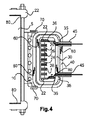
図3は、インナースリーブへの高圧巻線のボビンの取り付け、及びアウタースリーブへのインナースリーブの取り付けを平行2次元断面図において示す。簡略化のため、高圧変圧器の2分の1のみが示される。高圧変圧器は、磁気コア5と、低圧巻線10と、高圧巻線20と、少なくとも1つのインナースリーブ30と、高圧巻線20を担持するためのコイルボビン24とを含む。
FIG. 3 shows the attachment of the bobbin of the high voltage winding to the inner sleeve and the attachment of the inner sleeve to the outer sleeve in a parallel two-dimensional sectional view. For simplicity, only one half of the high voltage transformer is shown. The high voltage transformer includes a
任意選択的に、磁気コア5は、軟質磁性材料、例えば、強磁性体及び/又はフェリ磁性体で作製される。磁気コア5は、鉄若しくはニッケル、又は鉄若しくはニッケルの合金、又は金属のセラミック酸化物を含む。
Optionally, the
インナースリーブ30は、プラスチック材料又は任意の他の非導電合成若しくは半合成固体材料から作製される。
任意選択的に、低圧巻線10及び/又は高圧巻線20の巻線ワイヤは、銅若しくは銅合金、又はアルミニウム若しくはアルミニウム合金で作製され、巻線ワイヤは非常に薄い絶縁層でコーティングされる。 Optionally, the winding wires of low voltage winding 10 and / or high voltage winding 20 are made of copper or copper alloy, or aluminum or aluminum alloy, and the winding wire is coated with a very thin insulating layer.
任意選択的に、本発明の一実施形態においては、コイルボビン24は、各スロット内の電圧差が高圧巻線の終端部間の電圧差の僅か何分の1になるように複数のスロット26に分割される。巻線スロット間の薄い絶縁スロット28により、ボビン表面を越える放電を回避する。これら絶縁スロットは、また、1つのスロットの頂部から次のスロットの底部へと巻線ワイヤを戻すために使用されてもよい。
Optionally, in one embodiment of the present invention, the
コイルボビン24は、少なくとも1つのインナースリーブ30の内部に配置されるように構成され、少なくとも1つのインナースリーブ30の外周部において少なくとも1つのインナースリーブ30に取り付けられるように構成される。
The
コイルボビン24は、プラスチック材料又は任意の他の非導電合成若しくは半合成固体材料から作製される。
The
コイルボビン24は、高圧巻線20によって発生する電界を形成するように適合された少なくとも1つの電界制御電極22を含む。
The
磁気コア5は軟質磁気コアである。
The
高圧変圧器は少なくとも1つのアウタースリーブ40を更に含む。
The high voltage transformer further includes at least one
高圧変圧器は、少なくとも1つのアウタースリーブ40への少なくとも1つのインナースリーブ30の留め具35と、少なくとも1つのインナースリーブ30への高圧巻線20の留め具又はフランジ36と、を更に含む。
The high voltage transformer further includes a
高圧変圧器は、少なくとも1つの絶縁高圧ワイヤパイプ45を更に含む。高圧ワイヤパイプ45は、プラスチック材料又は任意の他の非導電合成若しくは半合成固体材料から作製される。高圧変圧器は、更に、高圧変圧器アセンブリにプレス式取付具(press−fixture)を取り付けることによって作製される。
The high voltage transformer further includes at least one insulated high
高圧変圧器50は、互いに対向して配置された少なくとも2つのラビリンスシール60を更に含む。ラビリンスシール60は、インナースリーブ30の上半分及び下半分にある構造として、又はアウタースリーブ40の上半分及び下半分にある構造として作製される。アウタースリーブ40は、プラスチック材料又は任意の他の非導電合成若しくは半合成固体材料から作製される。
The
高圧変圧器50は、高圧巻線20を保持するための少なくとも2つの絶縁スプリングワッシャー70を更に含む。絶縁スプリングワッシャー70は、プラスチック材料又は任意の他の非導電合成若しくは半合成固体材料から作製される。
The
図4は、本発明の例示的実施形態による高圧変圧器のコアに垂直な概略断面図を示す。 FIG. 4 shows a schematic cross-sectional view perpendicular to the core of the high voltage transformer according to an exemplary embodiment of the present invention.
図4は、インナースリーブへの高圧巻線のボビンの取り付け及びアウタースリーブへのインナースリーブの取り付けを垂直2次元断面図で示す。簡略化のため、高圧変圧器の2分の1のみが示される。 FIG. 4 shows a vertical two-dimensional cross-sectional view of the attachment of the bobbin of the high-voltage winding to the inner sleeve and the attachment of the inner sleeve to the outer sleeve. For simplicity, only one half of the high voltage transformer is shown.
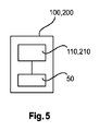
図5は、本発明の例示的実施形態によるX線システムを示す。 FIG. 5 illustrates an X-ray system according to an exemplary embodiment of the present invention.
X線システム100は、X線管110と、X線管110に給電するように構成された高圧変圧器50とを含む。
The x-ray system 100 includes an x-ray tube 110 and a
高電圧試験システム200は、高圧消費者210に給電するように構成された高圧変圧器50を含む。
High voltage test system 200 includes a
図6は、本発明の更なる例示的実施形態による高圧変圧器の概略斜視3次元投影図を示す。 FIG. 6 shows a schematic perspective three-dimensional projection of a high-voltage transformer according to a further exemplary embodiment of the invention.
図6に示されるような高圧変圧器は、コアエッジ部80上の電界制御電極22と、磁気コア5を覆うアルミニウムシェルと、を含み、電界制御電極22はコアエッジ部80上に配置されている。
The high voltage transformer as shown in FIG. 6 includes an electric
本発明は図面及び前述の明細書内で詳細に図示され、記載されてきたが、こうした図示及び記載は説明的又は例示的であり、限定ではないと考えられる。本発明は、開示される実施形態に限定されない。当業者には、開示される実施形態以外の変形形態が理解され、実施され得ると共に、図面、開示及び添付の特許請求の範囲の研究から、請求される発明が実施され得る。 Although the invention has been illustrated and described in detail in the drawings and foregoing specification, such illustration and description are to be considered illustrative or exemplary and not restrictive. The invention is not limited to the disclosed embodiments. Those skilled in the art can appreciate and implement variations other than the disclosed embodiments, and may practice the claimed invention from a study of the drawings, the disclosure, and the appended claims.
特許請求の範囲において、「含む(comprising)」という語は他の要素又はステップを排除するものではなく、不定冠詞「a」又は「an」は複数を排除するものではない。単一のプロセッサ、コントローラ又は他のユニットが特許請求の範囲で列挙した幾つかの物品の機能を満たしてもよい。特定の施策が相互に異なる従属請求項に列挙されるという単なる事実はこれら施策の組み合わせが効果的に使用され得ないことを示すものではない。特許請求の範囲のいかなる参照符号も範囲を限定するものと解釈されるべきではない。 In the claims, the word “comprising” does not exclude other elements or steps, and the indefinite article “a” or “an” does not exclude a plurality. A single processor, controller or other unit may fulfill the functions of several items recited in the claims. The mere fact that certain measures are recited in mutually different dependent claims does not indicate that a combination of these measures cannot be used effectively. Any reference signs in the claims should not be construed as limiting the scope.
5 磁気コア
10 低圧巻線
20 高圧巻線
22 電界制御電極
24 コイルボビン
26 スロット
28 絶縁スロット
30 インナースリーブ
35 留め具
36 留め具(フランジ)
40 アウタースリーブ
45 高圧ワイヤパイプ
50 高圧変圧器
60 ラビリンスシール
70 絶縁スプリングワッシャー
80 コアエッジ部
100 X線システム
110 X線管
200 高電圧試験システム
210 高圧消費者
5
40
Claims (13)
低圧巻線と、
高圧巻線と、
第1の密閉ボリュームを規定する密閉インナースリーブと、
第2の密閉ボリュームを規定し、当該第2の密閉ボリューム内で前記密閉インナースリーブを囲む密閉アウタースリーブと、
前記高圧巻線を担持するコイルボビンであって、前記第1の密閉ボリューム内で前記密閉インナースリーブの内部に配置され、前記密閉インナースリーブの外周部において前記密閉インナースリーブに取り付けられる、コイルボビンと、
を含み、
前記コイルボビンが、前記高圧巻線によって発生した電界を形成する少なくとも1つの電界制御電極を含む、高圧変圧器。 A magnetic core ,
Low voltage winding ,
High voltage winding ,
A sealed inner sleeve defining a first sealed volume ;
Defining a second closed volume, the closed outer sleeve surrounding the closed inner sleeves within the second closed volume,
A coil bobbin carrying said high voltage winding, the disposed inside of the sealed inner sleeve within a first sealed volume, Ru attached to the sealed inner sleeve in the outer peripheral portion of the closed inner sleeve, and the coil bobbin ,
Including
The high voltage transformer, wherein the coil bobbin includes at least one electric field control electrode that forms an electric field generated by the high voltage winding.
前記第1の密閉スリーブの外周部において前記第1の密閉スリーブに取り付けられることによって前記第1の内側ボリューム内に取り付けられる、コイルボビンと、
を含む、高圧変圧器のためのコイルボビンアセンブリ。 A first sealing sleeve defining a first inner volume ;
A coil bobbin attached within the first inner volume by being attached to the first sealing sleeve at an outer periphery of the first sealing sleeve ;
Including coil bobbin assembly for high voltage transformer .
を更に含む、請求項8に記載のコイルボビンアセンブリ。 The coil bobbin assembly of claim 8, further comprising:
前記磁気コアの一部分の周りに配置される低圧巻線と、 A low voltage winding disposed around a portion of the magnetic core;
前記低圧巻線の周りに配置され、外側の環状内側ボリュームを規定する、管状密閉アウタースリーブと、 A tubular sealed outer sleeve disposed around the low voltage winding and defining an outer annular inner volume;
前記管状密閉アウタースリーブの前記外側の環状内側ボリュームの内部に配置され、内側の環状内側ボリュームを規定する、管状密閉インナースリーブと、 A tubular sealed inner sleeve disposed within the outer annular inner volume of the tubular sealed outer sleeve and defining an inner annular inner volume;
前記管状密閉インナースリーブの外縁を、離間された関係で前記管状密閉アウタースリーブに取り付ける留め具と、 A fastener for attaching an outer edge of the tubular sealed inner sleeve to the tubular sealed outer sleeve in a spaced relationship;
前記内側の環状内側ボリューム内に配置されるコイルボビンであって、当該コイルボビンを前記内側の環状内側ボリューム内で支持するために、前記管状密閉インナースリーブの外周部に接続されたフランジを含む、コイルボビンと、 A coil bobbin disposed in the inner annular inner volume, the coil bobbin including a flange connected to an outer periphery of the tubular sealed inner sleeve to support the coil bobbin in the inner annular inner volume; ,
前記コイルボビンによって担持される高圧巻線と、 A high voltage winding carried by the coil bobbin;
前記コイルボビンによって担持され、前記高圧巻線によって発生した電界を形成する少なくとも1つの電界制御電極と、 At least one electric field control electrode carried by the coil bobbin and forming an electric field generated by the high voltage winding;
を含む、高圧変圧器。 Including high voltage transformer.
Applications Claiming Priority (3)
| Application Number | Priority Date | Filing Date | Title |
|---|---|---|---|
| EP13198581.4 | 2013-12-19 | ||
| EP13198581 | 2013-12-19 | ||
| PCT/EP2014/077373 WO2015091202A1 (en) | 2013-12-19 | 2014-12-11 | High voltage transformer comprising a coil bobbin for carrying a high voltage winding |
Publications (3)
| Publication Number | Publication Date |
|---|---|
| JP2017508274A JP2017508274A (en) | 2017-03-23 |
| JP2017508274A5 JP2017508274A5 (en) | 2018-09-06 |
| JP6400710B2 true JP6400710B2 (en) | 2018-10-03 |
Family
ID=49880480
Family Applications (1)
| Application Number | Title | Priority Date | Filing Date |
|---|---|---|---|
| JP2016539948A Active JP6400710B2 (en) | 2013-12-19 | 2014-12-11 | High voltage transformer including a coil bobbin for carrying a high voltage winding |
Country Status (5)
| Country | Link |
|---|---|
| US (1) | US10090097B2 (en) |
| EP (1) | EP3084782B1 (en) |
| JP (1) | JP6400710B2 (en) |
| CN (1) | CN105940471A (en) |
| WO (1) | WO2015091202A1 (en) |
Families Citing this family (3)
| Publication number | Priority date | Publication date | Assignee | Title |
|---|---|---|---|---|
| WO2021084637A1 (en) * | 2019-10-30 | 2021-05-06 | 三菱電機株式会社 | Solenoid device and starter |
| CN111799073B (en) * | 2020-07-22 | 2023-05-12 | 中南大学 | High-voltage winding framework of high-power high-frequency transformer |
| DE102022214442A1 (en) | 2022-12-29 | 2024-07-04 | Siemens Healthineers Ag | X-ray generator and X-ray device |
Family Cites Families (13)
| Publication number | Priority date | Publication date | Assignee | Title |
|---|---|---|---|---|
| GB709361A (en) * | 1951-10-09 | 1954-05-19 | Moser Glaser & Co Ag | Improvements relating to high-voltage electric transformers |
| US4514712A (en) * | 1975-02-13 | 1985-04-30 | Mcdougal John A | Ignition coil |
| JPS622738Y2 (en) * | 1980-05-20 | 1987-01-22 | ||
| DE3605629A1 (en) * | 1986-02-21 | 1987-09-03 | Koch & Sterzel Kg | HIGH VOLTAGE TRANSFORMER |
| DE4021585A1 (en) * | 1990-07-06 | 1992-01-09 | Philips Patentverwaltung | HIGH VOLTAGE TRANSFORMER, ESPECIALLY FOR A X-RAY DEVICE |
| DE4204092C2 (en) * | 1992-02-12 | 1993-12-16 | Ant Nachrichtentech | Coil former for at least one winding chamber for electrical material to be wound, in particular for a high-voltage transformer, and high-voltage transformer |
| US5847518A (en) * | 1996-07-08 | 1998-12-08 | Hitachi Ferrite Electronics, Ltd. | High voltage transformer with secondary coil windings on opposing bobbins |
| JPH118140A (en) * | 1997-06-16 | 1999-01-12 | Ngk Spark Plug Co Ltd | High-voltage transformer |
| TW369654B (en) * | 1997-07-07 | 1999-09-11 | Thomson Brandt Gmbh | Diode-split high-voltage transformer |
| JP2000357617A (en) * | 1999-06-15 | 2000-12-26 | Matsushita Electric Ind Co Ltd | Transformer of power supply for driving magnetron |
| DE102004033280A1 (en) * | 2004-07-09 | 2006-02-02 | Robert Bosch Gmbh | Injector for fuel injection |
| JP2006237420A (en) | 2005-02-28 | 2006-09-07 | Hitachi Media Electoronics Co Ltd | Transformer and power supply device |
| EP2653015B1 (en) | 2010-12-15 | 2014-04-16 | Koninklijke Philips N.V. | Power supply unit for an X-ray tube |
-
2014
- 2014-12-11 EP EP14812213.8A patent/EP3084782B1/en active Active
- 2014-12-11 WO PCT/EP2014/077373 patent/WO2015091202A1/en active Application Filing
- 2014-12-11 JP JP2016539948A patent/JP6400710B2/en active Active
- 2014-12-11 CN CN201480069574.2A patent/CN105940471A/en active Pending
- 2014-12-11 US US15/105,603 patent/US10090097B2/en active Active
Also Published As
| Publication number | Publication date |
|---|---|
| EP3084782B1 (en) | 2019-05-22 |
| EP3084782A1 (en) | 2016-10-26 |
| US10090097B2 (en) | 2018-10-02 |
| US20160314898A1 (en) | 2016-10-27 |
| CN105940471A (en) | 2016-09-14 |
| JP2017508274A (en) | 2017-03-23 |
| WO2015091202A1 (en) | 2015-06-25 |
Similar Documents
| Publication | Publication Date | Title |
|---|---|---|
| JP6400710B2 (en) | High voltage transformer including a coil bobbin for carrying a high voltage winding | |
| US20220384087A1 (en) | Inductor Coil and Electromagnetic Component | |
| JP2008153293A (en) | Transformer | |
| JP2016018882A (en) | Magnetic circuit component | |
| JP2011124293A5 (en) | ||
| US20150228393A1 (en) | High-Voltage Transformer Apparatus with Adjustable Leakage | |
| US11217377B2 (en) | Low inter-winding capacitance coil form | |
| JP2009176462A (en) | X-ray generating device | |
| KR102343120B1 (en) | Potable X-ray Generator | |
| CN103052248A (en) | Voltage-multiplying-type high-voltage rectifying oil tank | |
| CN110391073B (en) | Circuit arrangement, X-ray device and computed tomography scanner | |
| JP6532233B2 (en) | Insulation transformer and radiation generator provided with the same, radiography system | |
| JP2017508274A5 (en) | ||
| JP2015133353A (en) | Induction apparatus | |
| JP2019510371A (en) | Electromagnetic induction device and manufacturing method thereof | |
| CN212275949U (en) | Gradient coil | |
| JP2017120715A (en) | X-ray generation apparatus and x-ray imaging system | |
| JP2018107102A (en) | Plasma generation device | |
| WO2015158200A1 (en) | Fixing device of magnetic element, annular transformer and annular reactor | |
| JP2018032717A (en) | Stationary induction apparatus | |
| JP7564148B2 (en) | Wireless power supply module and wireless power supply system | |
| WO2016071123A1 (en) | Resonant converter | |
| JP2014203977A (en) | Power transformer | |
| JP6292484B2 (en) | Plasma generator (embodiments) | |
| RU124041U1 (en) | THREE-PHASE TRANSFORMER |
Legal Events
| Date | Code | Title | Description |
|---|---|---|---|
| A521 | Request for written amendment filed |
Free format text: JAPANESE INTERMEDIATE CODE: A523 Effective date: 20171208 |
|
| A621 | Written request for application examination |
Free format text: JAPANESE INTERMEDIATE CODE: A621 Effective date: 20171208 |
|
| A521 | Request for written amendment filed |
Free format text: JAPANESE INTERMEDIATE CODE: A523 Effective date: 20180727 |
|
| A871 | Explanation of circumstances concerning accelerated examination |
Free format text: JAPANESE INTERMEDIATE CODE: A871 Effective date: 20180727 |
|
| A975 | Report on accelerated examination |
Free format text: JAPANESE INTERMEDIATE CODE: A971005 Effective date: 20180727 |
|
| TRDD | Decision of grant or rejection written | ||
| A01 | Written decision to grant a patent or to grant a registration (utility model) |
Free format text: JAPANESE INTERMEDIATE CODE: A01 Effective date: 20180807 |
|
| A61 | First payment of annual fees (during grant procedure) |
Free format text: JAPANESE INTERMEDIATE CODE: A61 Effective date: 20180905 |
|
| R150 | Certificate of patent or registration of utility model |
Ref document number: 6400710 Country of ref document: JP Free format text: JAPANESE INTERMEDIATE CODE: R150 |
|
| R250 | Receipt of annual fees |
Free format text: JAPANESE INTERMEDIATE CODE: R250 |
|
| R250 | Receipt of annual fees |
Free format text: JAPANESE INTERMEDIATE CODE: R250 |
|
| R250 | Receipt of annual fees |
Free format text: JAPANESE INTERMEDIATE CODE: R250 |