JP6400591B2 - System and method for detecting missing tows in composite layups - Google Patents
System and method for detecting missing tows in composite layups Download PDFInfo
- Publication number
- JP6400591B2 JP6400591B2 JP2015540676A JP2015540676A JP6400591B2 JP 6400591 B2 JP6400591 B2 JP 6400591B2 JP 2015540676 A JP2015540676 A JP 2015540676A JP 2015540676 A JP2015540676 A JP 2015540676A JP 6400591 B2 JP6400591 B2 JP 6400591B2
- Authority
- JP
- Japan
- Prior art keywords
- tow
- thermal image
- substrate
- real
- composite layup
- Prior art date
- Legal status (The legal status is an assumption and is not a legal conclusion. Google has not performed a legal analysis and makes no representation as to the accuracy of the status listed.)
- Active
Links
Images


Classifications
-
- B—PERFORMING OPERATIONS; TRANSPORTING
- B32—LAYERED PRODUCTS
- B32B—LAYERED PRODUCTS, i.e. PRODUCTS BUILT-UP OF STRATA OF FLAT OR NON-FLAT, e.g. CELLULAR OR HONEYCOMB, FORM
- B32B41/00—Arrangements for controlling or monitoring lamination processes; Safety arrangements
-
- B—PERFORMING OPERATIONS; TRANSPORTING
- B29—WORKING OF PLASTICS; WORKING OF SUBSTANCES IN A PLASTIC STATE IN GENERAL
- B29C—SHAPING OR JOINING OF PLASTICS; SHAPING OF MATERIAL IN A PLASTIC STATE, NOT OTHERWISE PROVIDED FOR; AFTER-TREATMENT OF THE SHAPED PRODUCTS, e.g. REPAIRING
- B29C70/00—Shaping composites, i.e. plastics material comprising reinforcements, fillers or preformed parts, e.g. inserts
- B29C70/04—Shaping composites, i.e. plastics material comprising reinforcements, fillers or preformed parts, e.g. inserts comprising reinforcements only, e.g. self-reinforcing plastics
- B29C70/28—Shaping operations therefor
- B29C70/30—Shaping by lay-up, i.e. applying fibres, tape or broadsheet on a mould, former or core; Shaping by spray-up, i.e. spraying of fibres on a mould, former or core
- B29C70/38—Automated lay-up, e.g. using robots, laying filaments according to predetermined patterns
-
- G—PHYSICS
- G01—MEASURING; TESTING
- G01N—INVESTIGATING OR ANALYSING MATERIALS BY DETERMINING THEIR CHEMICAL OR PHYSICAL PROPERTIES
- G01N25/00—Investigating or analyzing materials by the use of thermal means
- G01N25/72—Investigating presence of flaws
Description
複合材構造体は、予め含浸された繊維のトウの連続細片又は帯(バンド)をツール又はマンドレル上に貼付して、複数のプライを有する複合材レイアップを形成する、自動繊維配置マシンを使用して製造されることがある。各トウは、樹脂を使用して端部と端部とで接合される幾つかのトウセグメントからなることがある。トウは、繊維配置ヘッド上に装着される複数のトウスプールから引き出されてもよい。繊維配置ヘッドは、トウバンドを形成するため、複数のトウが互いに隣接した配置に揃えるトウコリメータを含んでもよい。トウバンドはトウコリメータから繊維配置ヘッドの貼付装置に供給され、繊維配置ヘッドがツールに沿ってツール表面の輪郭線にたどるにつれて、トウはツール又はマンドレル上に押圧される。 The composite structure is an automatic fiber placement machine that applies a continuous strip or band of pre-impregnated fiber tows onto a tool or mandrel to form a composite layup with multiple plies. May be manufactured using. Each tow may consist of several tow segments that are joined end to end using resin. The tow may be drawn from a plurality of tous pools mounted on the fiber placement head. The fiber placement head may include a toe collimator that aligns a plurality of tows adjacent to each other to form a tow band. The tow band is fed from the tow collimator to the fiber placement head applicator, and as the fiber placement head follows the tool surface contour along the tool, the tow is pressed onto the tool or mandrel.
時折、トウバンドをツール表面に貼付するプロセスの間に、コリメータを経由する又は繊維配置ヘッドの他のコンポーネントを経由するトウの供給ミスなどによって、トウバンドからトウが欠損することがある。トウはまた、トウの接合部の断裂によって欠損することもある。加えて、トウとツール表面又は基板との間の連結が不十分な状態でトウがツールに貼付された後、トウがツール表面から脱落することによって、欠損することがある。 Occasionally during the process of applying the tow band to the tool surface, the tow may be lost from the tow band, such as through a misfeed of the tow via a collimator or other component of the fiber placement head. The tow can also be lost by rupturing the tow joint. In addition, after the tow is affixed to the tool in a state where the connection between the tow and the tool surface or the substrate is insufficient, the tow may fall off from the tool surface.
欠損トウを検出する従来の方法は、欠損トウを示唆するレイアップ表面の陥凹の存在を探す複合材レイアップの目視検査を含む。残念ながら、各トウの厚みは比較的小さく(例えば、0.008インチ)、幅も比較的小さい(例えば、0.125インチ)ため、レイアップ表面上の陥凹を検出することは困難となる。加えて、人の眼による目視検査でレイアップ表面上の陥凹を検出することは、複合材レイアップが同一繊維方向のトウを有する重複プライから成り、トウが黒色であるためにコントラストが最小となるような場合には、さらに困難になることがある。レイアップ表面の触覚検査は、ある種の複合材構造体に関連する比較的大きな面積では、実用的でないことがある。加えて、触覚検査では、所望の結果が得られないことがある。 Conventional methods for detecting missing tows include visual inspection of composite layups looking for the presence of layup surface depressions suggesting missing tows. Unfortunately, the thickness of each tow is relatively small (eg, 0.008 inches) and the width is relatively small (eg, 0.125 inches), making it difficult to detect depressions on the layup surface. . In addition, the detection of depressions on the layup surface by visual inspection with the human eye means that the composite layup consists of overlapping plies with tows in the same fiber direction and the contrast is minimal because the tows are black. May be even more difficult. Lay-up surface tactile inspection may not be practical in the relatively large areas associated with certain composite structures. In addition, the tactile examination may not provide the desired results.
欠損トウを検出する従来の方法に関連して更に問題となるのは、繊維配置マシンが、トウバンドにトウが欠損した状態で複合材料の貼付を継続することである。例えば、複合材料の多重プライは、欠損トウが検出されて繊維配置マシンが停止される前に、トウが欠損した状態で領域上に積層される。トウが欠損している複合材レイアップの領域で再作業を行うには、トウが欠損している領域全体を大まかに特定しなければならない。しかしながら、複合材レイアップの再作業には、大きな費用をかけて、労働集約的で長時間を要するプロセスで材料の除去と交換が必要となることがある。しかも、トウの欠損領域は大まかにしかわからないため、欠損トウの正確な場所に到達するまでには、大量の材料の除去が必要となることがある。 A further problem associated with conventional methods of detecting missing tows is that the fiber placement machine continues to apply the composite material with the tows in the tow band. For example, multiple plies of composite material are stacked on a region with the tow missing before the tow is detected and the fiber placement machine is stopped. To re-work in a composite layup region where the tow is missing, the entire region where the tow is missing must be roughly identified. However, reworking composite layups can be costly and require material removal and replacement in a labor intensive and time consuming process. In addition, since the toe defect region is only roughly known, it may be necessary to remove a large amount of material before reaching the exact location of the tow defect.
このように、当該技術分野においては、より高い精度で複合材レイアップ中の欠損トウを検出するためのシステム及び方法が必要とされている。加えて、当該技術分野においては、再作業中に取り除かれる複合材料の量を最小限にするため、欠損トウの正確な場所が特定され得るような、複合材レイアップ中の欠損トウを検出するためのシステム及び方法が必要とされている。 Thus, there is a need in the art for systems and methods for detecting missing tows in composite layups with higher accuracy. In addition, the art detects defective tows in composite layups so that the exact location of the defective tows can be identified to minimize the amount of composite material removed during rework. What is needed is a system and method for achieving this.
欠損トウの検出に関連する上述の必要性は、トウバンド中の欠損トウを検出するためのシステムを提供する本開示によって、具体的に対処され軽減される。本システムは、トウバンドを基板に貼付して複合材レイアップを形成するための繊維配置ヘッドを含むことがある。本システムはさらに、トウバンドの貼付の前に、基板を予熱するための加熱装置を含むことがある。本システムは追加的に、繊維配置ヘッドに装着され、トウバンドを基板に貼付する間に、複合材レイアップのリアルタイム熱画像を生成するように構成された赤外線カメラを含むことがある。 The above-described need associated with detecting defective tows is specifically addressed and mitigated by the present disclosure that provides a system for detecting defective tows in tow bands. The system may include a fiber placement head for applying a tow band to a substrate to form a composite layup. The system may further include a heating device for preheating the substrate prior to application of the tow band. The system may additionally include an infrared camera attached to the fiber placement head and configured to generate a real-time thermal image of the composite layup while applying the tow band to the substrate.
更なる実施形態では、トウバンド中の欠損トウを検出するためのシステムが開示される。本システムは、トウバンドを基板に貼付して複合材レイアップを形成するように構成されている繊維配置ヘッドを含むことがある。本システムは更に、圧縮ローラの前方に位置付けられ、圧縮ローラを使用してトウバンドを貼付する前に、基板を予熱するように構成される赤外線加熱器を含むことがある。加えて、本システムは、繊維配置ヘッドに装着され、トウバンドを基板に貼付する間に、複合材レイアップのリアルタイム熱画像を生成するように構成される赤外線カメラを含むことがある。本システムはまた、複合材レイアップのリアルタイム熱画像を表示するため、赤外線カメラに結合されるディスプレイ装置を含むことがある。 In a further embodiment, a system for detecting a defective tow in a tow band is disclosed. The system may include a fiber placement head configured to affix a tow band to a substrate to form a composite layup. The system may further include an infrared heater positioned in front of the compression roller and configured to preheat the substrate prior to applying the tow band using the compression roller. In addition, the system may include an infrared camera mounted on the fiber placement head and configured to generate a real-time thermal image of the composite layup while applying the tow band to the substrate. The system may also include a display device coupled to the infrared camera for displaying real-time thermal images of the composite layup.
また、複合材レイアップ中の欠損トウを検出する方法が開示されている。本方法はまた、トウバンドを基板に貼付する前に基板を予熱すること、及びトウバンドを基板に貼付して複合材レイアップを形成することを含むことがある。本方法はまた追加的に、トウバンドが基板に貼付される間に複合材レイアップのリアルタイム熱画像を生成すること、及びリアルタイム熱画像に基づいてトウが欠損しているかどうかを決定することを含むことがある。 Also disclosed is a method for detecting missing tows in a composite layup. The method may also include preheating the substrate before applying the tow band to the substrate and applying the toe band to the substrate to form a composite layup. The method also additionally includes generating a real-time thermal image of the composite layup while the tow band is applied to the substrate, and determining whether the tow is missing based on the real-time thermal image. Sometimes.
特徴、機能及び利点は、本開示のさまざまな実施形態において独立して達成可能であり、又は、以下の説明及び図面を参照して更なる詳細が理解可能である更に他の実施形態において組み合わされてもよい。 The features, functions, and advantages can be achieved independently in various embodiments of the present disclosure, or may be combined in yet other embodiments that can be understood in further detail with reference to the following description and drawings. May be.
本開示のこれらの特徴及び他の特徴は、図面を参照することにより明確となり、全体を通して類似の参照番号は類似の部分を指す。 These and other features of the present disclosure will become apparent by reference to the drawings, wherein like reference numerals refer to like parts throughout.
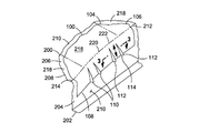
ここで、本開示の種々の実施形態の例示を目的とする図面を参照すると、図1は、トウバンド160の欠損トウ194(図4)を検出するためのトウ検出システム100の斜視図である。トウ検出システム100は、プリプレグトウバンド160又はプリプレグ複合材テープを基板166に貼付して、複合材部品の複合材レイアップ164を形成するための自動繊維配置マシン150に実装されてもよい。基板166は、固定ツール168又は回転マンドレル(図示せず)のツール表面を含み得る、或いは基板166は予め積層されたトウバンド160のコース162を含み得る。自動繊維配置マシン150は、トウ154を基板166に貼付するための一又は複数の繊維配置ヘッド152を含み得る。
Referring now to the drawings for purposes of illustrating various embodiments of the present disclosure, FIG. 1 is a perspective view of a
上に示したように図1を参照すると、トウバンド160の各々は、複数の個別のトウ154からなることがある。トウ154の各々は、樹脂被覆強化繊維の束として形成されてもよい。各トウ154は、約0.12〜0.50インチの範囲の比較的小さな幅又は直径で提供されることがあるが、より大きな幅も可能である。トウ154は一又は複数のスプール(図示せず)から供給され、図示のようにトウバンド160にトウ154を揃えるため、トウコリメータ153に通される。
Referring to FIG. 1 as indicated above, each
トウバンド160は、コース162を基板166上に貼付するようにプログラムされたシーケンスに従って、トウバンド160の起動停止運動を制御するため、一対の再起動ローラ170の間を通過することがある。コース162は、図1に図解されているように、互いに平行な配置で貼付されてもよい。トウバンド160は、各コース162の終端でトウ154を切断するように構成されているトウカッター及びクランプ機構を通過することもある。トウバンド160の新しい端部は、圧縮ローラ156に向かって再起動ローラによって押圧されてもよい。圧縮ローラ156は、トウバンド160を基板166に貼付し得る。圧縮ローラ156は、圧縮ローラ156がツール168の表面に沿って移動するにつれて、トウバンド160を基板166上に押圧するため、トウバンド160に圧縮圧を印加し得る。
The
図1では、繊維配置ヘッド152は、基板166の温度を上昇させるための加熱装置174を含み得る。加熱装置174は、トウバンド160が最初に基板166に接触する場所の前方に位置付けられてもよい。これに関連して、加熱装置174は、トウバンド160が基板166に対して圧迫される圧縮ローラ156の前方に位置付けられてもよい。ローラの前方は、繊維配置ヘッド152の前進運動の方向に対して定義される。
In FIG. 1, the
加熱装置174は、トウバンド160が基板166に接触する前に、基板166の表面を予熱するように構成されてもよい。基板166の熱は、トウバンド160と基板166と間の連結又は接着を高め得る。トウバンド160での連結を高めることによって、複合材部品のレイアップのプロセスの間に、個々のトウ154は基板166上で位置が維持され得る。加熱装置174は、基板166を加熱する及び/又はトウバンド160と基板166との接触の前にトウバンド160を予熱するための赤外線加熱器178など、放射加熱器176として提供されてもよい。しかしながら、加熱装置174は、強制熱風加熱器180などの代替的な構成で提供されてもよい。
The
図1、2を参照すると、自動繊維配置マシン150は赤外線カメラ182を含み得る。赤外線カメラ182は、繊維配置ヘッド152に装着され、トウバンド160を基板166に貼付する間に、複合材レイアップ164のリアルタイム熱画像188を生成するように構成されてもよい。一実施形態では、赤外線カメラ182は、繊維配置ヘッド152がツール168に沿って移動するにつれて、複合材レイアップ164のリアルタイム熱画像188を記録するように構成されてもよい。これに関連して、赤外線カメラ182は、トウバンド160が基板166に対して圧迫される場所の後方に位置付けられてもよい。圧縮ローラ156を有する繊維配置ヘッド152の実施形態に関して、赤外線カメラ182は繊維配置ヘッド152の前進運動の方向に対して、圧縮ローラ156の後方に位置付けられてもよい。
With reference to FIGS. 1 and 2, the automatic
図2では、赤外線カメラ182は、トウバンド160が圧縮ローラ156によって配置される領域に、複合材レイアップ164の視野(図示せず)を捕捉するように構成されてもよい。このように、赤外線カメラ182は、赤外線加熱器178による基板166の加熱に応答して、トウバンド160の画像を記録してもよい。これに関連して、赤外線加熱器178は、ツール168表面に予め貼付されているトウバンド160を加熱してもよい。赤外線カメラ182の視野は、好ましくは少なくともトウバンド160の幅を捕捉する。例えば、赤外線カメラ182は、トウ154の各々が約0.5インチ以上のトウ154幅で、トウバンド160の全幅が約8インチとなるようなトウを有するトウバンド160の実質的な大部分を捕捉し得る視野を有することがある。しかしながら、赤外線カメラ182は、任意の大きさのトウバンド幅を捕捉し得る視野を有してもよい。
In FIG. 2, the
赤外線カメラ182は、繊維配置ヘッド152がツール168に沿って移動するにつれて、トウバンド160のリアルタイム熱画像188を表示するため、図2に示すようにディスプレイ装置110と通信可能に結合されてもよい。対角線長が14インチのモニタなど、比較的大きなディスプレイ装置110では、欠損トウ194の熱画像がディスプレイ装置110上で約0.75インチの幅で表示され得るように、約8インチのトウバンド幅は少なくとも約50%拡大されてもよい。ディスプレイ装置110は、繊維配置マシン150のオペレータが見るように構成されてもよい。比較的高い解像度の赤外線カメラ182で、リアルタイム熱画像188を拡大すると、リアルタイム熱画像188の目視検査(例えば、人の眼による)などによるトウバンド160中の欠損トウ194の検出は、トウバンド160の残存部分に対する欠損トウ194の領域の熱の痕跡190の局所的な差異192を明らかにし得る。これに関連して、本明細書で開示されているトウ検出システム100は、欠損トウ194を検出するための従来の方法と比較して、大幅な改善を示している。
The
図2において、一実施形態では、赤外線カメラ182は、ディスプレイ装置110も結合され得るプロセッサ102(例えば、コンピュータ)と通信可能に結合されてもよい。プロセッサ102は、キーボード、グラフィカルユーザインターフェースなどのユーザインターフェース108、或いは自動繊維配置マシン150の動作中にカメラのズームや視野を変更することなど、オペレータがプロセッサ102とやりとりすること及び/又は赤外線カメラ182を制御することを可能にする他の装置を含み得る。一実施形態では、赤外線カメラ182は、トウ154を基板166に貼付する間に、連続的に、間欠的に、或いは定期的に自動動作するように構成されてもよい。
In FIG. 2, in one embodiment, the
更なる実施形態では、ユーザインターフェース108はオペレータによる赤外線カメラ182の手動制御を促進し得る。例えば、ユーザインターフェース108は、トウバンド160を基板166に貼付する間に、複合材レイアップ164のリアルタイム熱画像188の記録を任意の点で開始及び停止するなど、想定されるカメラの操作又は制御を促すことがある。プロセッサ102はまた、自動繊維配置マシン150の事前にプログラムされたトウ貼付シーケンスの手動による無効操作を促進するように構成されてもよい。例えば、ディスプレイ装置110上での複合材レイアップ164のリアルタイム熱画像188の目視観測によって、欠損トウ194が検出されると、オペレータは欠損トウ154の処理を可能にするため、繊維配置マシン150の操作を中断又は一時的に停止してもよい。
In further embodiments, the
プロセッサ102は、自動繊維配置マシン150の動作中などに赤外線カメラ182によって記録されたリアルタイム熱画像188(例えば、ビデオ)をオペレータが目視観察できるようにするため、複合材レイアップ164の一又は複数の熱画像を表示するためのディスプレイ装置110を含み得る。プロセッサ102は付加的に、リアルタイム熱画像188(図4)の複合材レイアップ164の熱の痕跡190を、以下で説明するように基準熱画像186(図3)の複合材レイアップ164の熱の痕跡190と比較することによって、トウ154がトウバンド160から欠損しているかどうかを決定するように構成されてもよい。
The processor 102 may include one or more
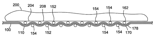
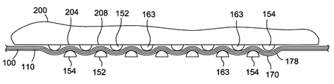
図3、4を参照すると、図3には複合材レイアップ164の基準熱画像186が示されている。図4には、繊維配置ヘッド152の圧縮ローラ156の後方に装着された赤外線カメラ182によって記録される、複合材レイアップ164のリアルタイム熱画像188が示されている。図3では、基準熱画像186中の複合材レイアップ164は、繊維配置ヘッド152によってツール168上に形成され、図4のリアルタイム熱画像188によって表示される複合材レイアップ164と同一の構成を有することがある。一実施形態では、基準熱画像186は、同一の大きさ、形状、及び材料構成を有し、リアルタイム熱画像188に示される複合材レイアップ164中の少なくとも1つのトウバンド160と同じ方法で(例えば、隣接して)配置されるトウ154を含む、少なくとも1つのトウバンド160から成る複合材レイアップ164を示すことがある。
Referring to FIGS. 3 and 4, a reference
図3、4では、比較器104は、リアルタイム熱画像188の複合材レイアップ164の熱の痕跡190を、基準熱画像186の複合材レイアップ164の熱の痕跡190と比較することによって、トウ154がトウバンド160から欠損しているかどうかを決定するように構成され得る。例えば、図4のリアルタイム熱画像188に示されている複合材レイアップ164は欠損トウを含み得る。リアルタイム熱画像188では、欠損トウ194は、同一トウバンド160の残存部分の熱の痕跡190と比較して、欠損トウ194の領域中の熱の痕跡190の局所的な差異192として示されることがある。欠損トウ194の領域中の熱の痕跡190の差異は、欠損トウ194の両側(例えば、縦方向のエッジ)で、トウ154を通って上向きに放射される熱量と比較して、より大量の熱が下層基板166(例えば、ツール168の表面又は予め貼付されているトウ)から、欠損トウ194によるトウバンド160の間隙を通って上方に放射される結果として生ずることがある。
3 and 4, the
例えば、複合材レイアップ164の基準熱画像186では、トウバンド160の各々は、一般的に一様な(例えば、一様に黒い)色又は陰影を有し、これは、下層基板166からトウバンド160を通る上向きの実質的に一様な熱放射があることを示している。複合材レイアップ164のリアルタイム熱画像188の中では、欠損トウ194を有するトウバンド160は、一様でない色又は陰影を有することがある。より具体的には、欠損トウ194の領域は、赤外線カメラ182で記録されたリアルタイム熱画像188中では一様に黒く見えるトウバンド160の残存部分に対して、色又は陰影がより明るく見えることがある。
For example, in the reference
図4は、欠損トウ194の領域中のトウバンド160の熱の痕跡190に、局所的な差異192があることを示している。各欠損トウ194は、欠損トウの長さ198及び欠損トウの幅196を有する。欠損トウの幅196は、トウバンド160の残存トウ154の幅と同等である。上述のように、現在入手可能な赤外線カメラ182の解像度では、欠損トウ194は、上述の熱の痕跡190中の局所的な差異192に基づく、人の眼による目視検査によって、リアルタイム熱画像188中で検出可能である。ライン上での人手による検出はまた、上述のように、赤外線カメラ182によって記録されたリアルタイム熱画像188を拡大することによって効率化され得る。
FIG. 4 shows that there is a local difference 192 in the thermal signature 190 of the
図4では、プロセッサ102は、複合材レイアップ164の参照点204を参照することなどによって、欠損トウ194の配置及び/又は位置を特定するように構成され得る。例えば、参照点204は、トウレイダウンプログラム106に関連付けられた基準座標系208の所定の縦配置及び/又は横配置を含み得る。トウレイダウンプログラム106は、トウバンド160のコース162を基板166に貼付するため、自動繊維配置マシン150の操作を制御するコンピュータ可読命令を有する数値制御(NC)プログラムなどのコンピュータプログラムを含み得る。別の実施形態では、トウレイダウンプログラム106は、繊維配置ヘッド152を操作するためのNCプログラムを含み得る。プロセッサ102は、NCプログラムに関連付けられた参照点204に関して、欠損トウ194の両端部の場所を特定するように構成され得る。一実施形態では、参照点204は、複合材レイアップ164に関連付けされ得る構造的特徴206を含み得る。例えば、胴体のバレル部分の外板を生成するため、マンドレル上の複合材レイアップ164では、複合材レイアップ164中の欠損トウ194の場所は、外板が取り付けられるストリンガー又はフレームステーションに対して特定され得るこれに関連して、プロセッサ102は、トウレイダウンプログラム106に対して欠損トウ194の場所を指示するように構成されてもよい。
In FIG. 4, the processor 102 may be configured to determine the placement and / or position of the missing tow 194, such as by referring to the
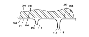
図5を参照すると、図4の欠損トウバンド160を図解する複合材レイアップ164の側面断面図が示され、欠損トウバンド160は複合材レイアップ164中のプライの深さ212に位置付けられている。一実施形態では、赤外線カメラ182は、タイムスタンプ202(図2)を赤外線カメラ182によって記録されたリアルタイム熱画像188と共に記録するように構成されてもよい。これに関連して、赤外線カメラ182は、複合材レイアップ164のリアルタイム熱画像188を記録する間に、時間を連続的に記録するように構成されてもよい。一実施形態では、タイムスタンプ202は、複合材レイアップ164のリアルタイム熱画像188と共に、ディスプレイ装置110上に表示されてもよい。欠損トウ194が検出されると、プロセッサ102は、タイムスタンプ202をプライの深さ212に関連付けるように構成されてもよい。一実施形態では、プライの深さ212は、プライスタック214の表面の下のプライの場所に関して定義されてもよい。プライスタック214は、繊維配置ヘッド152を制御するNCプログラムに関連付けられた積層シーケンス200によって定義されてもよい。
Referring to FIG. 5, a side cross-sectional view of a
レイアッププロセス中の後の段階で、欠損トウ194によって引き起こされた陥凹が複合材レイアップ164中に検出された場合には、レイアップシーケンス中でトウ194が欠損した時点(例えば、タイムスタンプ202)を決定するため、リアルタイム熱画像188を記録したビデオを再閲覧することができる。タイムスタンプ202(図2)は、NCプログラムに関連する積層シーケンス200中のプライの位置に関連付けられる。再作業は、既存のプライ材料を取り除き、層間修復を実施することなく、欠損トウ194の領域内で、複合材レイアップ164表面上にトウ154のオーバーレイを追加することによって、実施され得る。
If, at a later stage in the layup process, a recess caused by the missing tow 194 is detected in the
既に示したように、プロセッサ102は、欠損トウ194のプライの深さ212に対応する複合材レイアップ164中の欠損トウ194の縦位置(図示せず)及び/又は横位置(例えば、図4のコース配置210)を特定するように構成され得る。例えば、胴体のバレル部分のレイアップ中には、欠損トウ194のリアルタイム熱画像188のタイムスタンプ202は、プライシーケンス216及びバレル部分の欠損トウ194を示し得る。このように、プロセッサ102は、欠損トウの場所を正確に特定し、欠損トウを検出する従来の方法を使用して要求される再作業量と比較して、複合材レイアップ164上での再作業量を低減し得る手段を提供する。上述のように、このような再作業は、欠損トウ194の領域に重なり合っている一又は複数の複合プライの除去、及び欠損トウ194の領域を設計許容誤差の範囲内に収めるため、複合パッチでプライを置き換えることを要求し得る。
As already indicated, the processor 102 may have a longitudinal position (not shown) and / or a lateral position (eg, FIG. 4) of the defective tow 194 in the
図6を参照すると、自動繊維配置マシン150などの上の複合材レイアップ164中の欠損トウ194を検出するためのトウ検出システム100のブロック図が示されている。図6では、自動繊維配置マシン150は、繊維配置ヘッド152によって基板166に貼付されたトウバンド160のリアルタイム熱画像188に関して上記に示されているように、赤外線カメラ182を含み得る。自動繊維配置マシン150は、記憶装置(図示せず)に保存され、繊維配置ヘッド152の操作を制御するプロセッサ102と通信可能に結合されているトウレイダウンプログラム106によって制御されうる。プロセッサ102は、上述のように、複合材レイアップ164のリアルタイム熱画像188を複合材レイアップ164の基準熱画像186と比較するための比較器104を含み得る。図2に示すように、リアルタイム熱画像188は、任意選択のタイムスタンプ202と共に、ディスプレイ装置110上に表示されてもよい。プロセッサ102は、赤外線カメラの操作及び/又は繊維配置マシン150の操作を制御するためのユーザインターフェース108を含み得る。
Referring to FIG. 6, a block diagram of a
図7を参照すると、トウバンド160中の欠損トウ194を検出する方法300の一実施形態に含まれ得る一又は複数の操作を図解するフロー図が示されている。本方法はまた、テープ積層操作での欠損テープを検出するために実装され得る。
Referring to FIG. 7, a flow diagram illustrating one or more operations that may be included in one embodiment of a
図7の方法300のステップ302は、トウ154が基板166に貼付される点158の前方の場所で基板166を予熱することを含み得る。例えば、予熱は、繊維配置ヘッド152の圧縮ローラ156の直前の場所で起こり得る。ステップ302は、樹脂を加熱するため、赤外線加熱器178などの放射加熱器176を使用して、基板166を予熱することを含み得る。方法は、トウバンド160の連結を改善するため、複合材レイアップ164のトウバンド160を基板166に貼付する前に、基板166を予熱することを含んでもよい。基板166は、ツール168の表面を含むことがあり、或いは基板166は予め貼付されたトウバンド160を含むことがある。
Step 302 of the
図7の方法300のステップ304は、トウバンド160を基板166に貼付することを含むことがある。これに関連して、方法は、繊維配置ヘッド152を使用してトウバンド160を貼付することを含むことがある。例えば、図2に示すように、トウバンド160は、圧縮ローラ156でトウバンド160を基板166に押圧又は圧迫することによって、基板166に貼付されてもよい。これに関連して、圧縮ローラ156は、複合材レイアップ164の部分的な圧密化を促進し得る。
Step 304 of the
図7の方法300のステップ306は、トウバンド160が基板166に貼付される間に、複合材レイアップ164のリアルタイム熱画像188を生成することを含み得る。一実施形態では、方法は、赤外線カメラ182を使用して、リアルタイム熱画像188を生成することを含み得る。これに関連して、方法は、トウ154が基板166に貼付される点158の後方に赤外線カメラ182を位置付けることを含み得る。例えば、ステップ306は、ヘッドの運動方向184に対して繊維配置ヘッド152の圧縮ローラ156の後方に赤外線カメラ182を位置付けることを含んでもよい。本方法は、繊維配置ヘッド152がヘッドの運動方向184に沿って移動している間に、リアルタイム熱画像188を生成することを含み得る。赤外線カメラ182は、上述のように連続的に、間欠的に、又は手動の指示に基づいて、リアルタイム熱画像188を記録又は生成するように構成されてもよい。
Step 306 of the
一実施形態では、本方法は、赤外線カメラ182に結合されたディスプレイ装置110上にリアルタイム熱画像188を表示することを含み得る。本方法は、図4に関連して上述したように、欠損トウ194を示し得るトウバンド160内の熱の痕跡190中の局所的な差異192に関して、複合材レイアップ164のリアルタイム熱画像188を人の眼で目視検査すること(すなわち、手動検査)を含み得る。
In one embodiment, the method may include displaying real-time thermal image 188 on
図7の方法300のステップ308は、リアルタイム熱画像188を複合材レイアップ164の基準熱画像186と比較することを含む。例えば、本方法は、コンピュータに基づくシステム100のプロセッサ102の一部を形成する比較器104の使用を含むことがある。比較器104は、複合材レイアップ164の基準熱画像186に対する、複合材レイアップ164のリアルタイム熱画像188の比較解析を実施し得る。これに関連して、本方法は、基準熱画像186の複合材レイアップ164の熱の痕跡190に対する、複合材レイアップ164の熱の痕跡190の局所的な差異192に関して、複合材レイアップ164のリアルタイム熱画像188を自動検査することを含み得る。
Step 308 of the
図7の方法300のステップ310は、リアルタイム熱画像188と基準熱画像186との比較に基づいて、トウ154がトウバンド160から欠損しているかどうかを決定することを含み得る。本方法は更に、複合材レイアップ164中の一又は複数のトウバンド160が、リアルタイム熱画像188中に実質的に一様な熱の痕跡190を含むかどうかを決定することを含み得る。リアルタイム熱画像188の一様でない熱の痕跡190は欠損トウ194を示し得る。
Step 310 of
更なる実施形態において、本方法は、トウレイダウンプログラム106に対する欠損トウ194の場所を表示することを含み得る。例えば、本方法は、欠損トウ194が検出されたときにタイムスタンプ202を記録すること、及びタイムスタンプ202を複合材レイアップ164中の欠損トウ194の位置に関連付けることを含み得る。例えば、タイムスタンプ202は、積層シーケンス200の欠損トウ194のプライの深さ212、及び上述の欠損トウ194の縦又は横位置に関連付けられてもよい。
In further embodiments, the method may include displaying the location of the missing tow 194 relative to the
有利には、本明細書で開示されているシステム及び方法は、トウバンド160を基板166に貼付した直後に、複合材レイアップ164中の欠損トウ194を検出するための手段を提供し、これによって、欠損トウ194に貼付される複合材料の量を最小にすることができる。これに関連して、本明細書に開示されているシステム及び方法は、欠損トウ194の結果として、処理及び起こり得る再作業を保留にする繊維配置ヘッド152の操作を自動又は手動により一時停止する選択肢を提供する。更に、本明細書に開示されているシステム及び方法は、複合材レイアップ164中の欠損トウ194の場所を正確に特定するための手段を提供し、そうでない場合に要求される再作業の量を最小にすることができる。
Advantageously, the systems and methods disclosed herein provide a means for detecting defective tows 194 in
本開示の更なる修正及び改良は、当業者には明らかであろう。したがって、本明細書に説明され図示されている、部品の特定の組み合わせは、本開示のある種の実施形態のみを表すことを意図し、本開示の趣旨及び範囲に含まれる代替的な実施形態又は装置を限定することを意図していない。 Further modifications and improvements of the present disclosure will be apparent to those skilled in the art. Accordingly, the particular combinations of parts described and illustrated herein are intended to represent only certain embodiments of the present disclosure, and are alternative embodiments that fall within the spirit and scope of the present disclosure. Or it is not intended to limit the device.
クレームされる、もしくはクレームされない、本開示による内容の説明のための非網羅的実施例は、次の条項において提供される。
(条項1)
トウバンド中の欠損トウを検出するためのシステムであって、
トウバンドを基板に貼付して複合材レイアップを形成するように構成された繊維配置ヘッドと、
前記繊維配置ヘッドを使用して前記トウバンドを貼付する前に前記基板を予熱するように構成された加熱装置と、
前記繊維配置ヘッドに装着され、前記トウバンドを前記基板に貼付する間に、前記複合材レイアップのリアルタイム熱画像を生成するように構成された赤外線カメラと
を備えるシステム。
(条項2)
前記複合材レイアップの前記リアルタイム熱画像を表示するように構成されたディスプレイ装置を更に備える、条項1に記載のシステム。
(条項3)
前記赤外線カメラは、前記繊維配置ヘッドの前進運動の方向に対して、圧縮ローラの後方に位置付けられる、条項1に記載のシステム。
(条項4)
前記加熱装置は、前記繊維配置ヘッドの前進運動の方向に対して、圧縮ローラの前方に位置付けられる、条項1に記載のシステム。
(条項5)
前記赤外線カメラと通信可能に結合され、トウレイダウンプログラムに対して欠損トウの場所を指示するように構成されたプロセッサを更に備える、条項1に記載のシステム。
(条項6)
前記赤外線カメラは、欠損トウが検出されると、タイムスタンプを記録するように構成されており、
前記プロセッサは、前記タイムスタンプを前記複合材レイアップ中の前記欠損トウの位置に関連付けるように構成されている、条項5に記載のシステム。
(条項7)
前記プロセッサは前記タイムスタンプを積層シーケンス中のプライの深さに関連付けるように構成されている、条項6に記載のシステム。
(条項8)
前記リアルタイム熱画像での前記複合材レイアップの熱の痕跡と、基準熱画像の複合材レイアップの熱の痕跡とを比較することによって、トウが前記トウバンドから欠損しているかどうかを決定するように構成されている比較器を更に備える、条項1に記載のシステム。
(条項9)
トウバンド中の欠損トウを検出する方法であって、
基板を予熱するステップと、
前記トウバンドを前記基板に貼付して複合材レイアップを形成するステップと、
前記トウバンドが前記基板に貼付される間に、前記複合材レイアップのリアルタイム熱画像を生成するステップと、
前記リアルタイム熱画像に基づいて、トウが欠損しているかどうかを決定するステップと
を含む方法。
(条項10)
前記リアルタイム熱画像を生成する前記ステップは、
赤外線カメラを使用して前記リアルタイム熱画像を生成することを含む、条項9に記載の方法。
(条項11)
前記リアルタイム熱画像を生成する前記ステップは、
繊維配置ヘッドの圧縮ローラの後方に装着された前記赤外線カメラを使用して、前記リアルタイム熱画像を生成することを含む、条項10に記載の方法。
(条項12)
前記リアルタイム熱画像を生成する前記ステップは、
ヘッドの運動方向に沿って、前記繊維配置ヘッドを移動させる間に、前記リアルタイム熱画像を生成することを含む、条項11に記載の方法。
(条項13)
トウが欠損しているかどうかを決定する前記ステップは、
ディスプレイ装置上で、前記複合材レイアップの熱の痕跡中の局所的な差異を求めて、前記リアルタイム熱画像を目視検査することを含む、条項9に記載の方法。
(条項14)
前記熱の痕跡中の局所的な差異を求めて、前記リアルタイム熱画像を検査する前記ステップは、
前記トウバンドが実質的に一様な熱の痕跡を有するかどうかを決定することを含む、条項13に記載の方法。
(条項15)
トウが欠損しているかどうかを決定する前記ステップは、
前記複合材レイアップの前記リアルタイム熱画像の熱の痕跡と、前記複合材レイアップの基準熱画像の熱の痕跡とを比較することを含む、条項9に記載の方法。
(条項16)
欠損トウが検出されると、タイムスタンプを記録するステップと、
前記タイムスタンプを前記複合材レイアップ中の前記欠損トウの位置に関連付けるステップと
を更に含む、条項9に記載の方法。
(条項17)
前記タイムスタンプを積層シーケンス中のプライの深さに関連付けるステップを更に含む、条項16に記載の方法。
(条項18)
前記基板を予熱する前記ステップは、
前記トウが前記基板に貼付される点の直前で、前記基板の領域を加熱するように構成されている加熱装置を使用して、前記基板を予熱することを含む、条項9に記載の方法。
(条項19)
前記基板を予熱する前記ステップは、
放射加熱器及び強制熱風加熱器のうちの少なくとも1つを使用して、前記基板を予熱することを含む、条項9に記載の方法。
(条項20)
トウバンド中の欠損トウを検出するためのシステムであって、
トウバンドを基板に貼付して複合材レイアップを形成するように構成された繊維配置ヘッドと、
圧縮ローラの前方に位置付けられ、圧縮ローラを使用してトウバンドを貼付する前に前記基板を予熱するように構成された赤外線加熱器と、
前記繊維配置ヘッドに装着され、前記トウバンドを前記基板に貼付する間に、複合材レイアップのリアルタイム熱画像を生成するように構成された赤外線カメラと
前記赤外線カメラに結合され、前記複合材レイアップの前記リアルタイム熱画像を表示するように構成されたディスプレイ装置と
を備えるシステム。
Non-exhaustive examples for the explanation of the content according to the present disclosure, which are claimed or not claimed, are provided in the following clauses.
( Clause 1)
A system for detecting a defective tow in a tow band,
A fiber placement head configured to affix a tow band to a substrate to form a composite layup;
A heating device configured to preheat the substrate before applying the tow band using the fiber placement head;
An infrared camera mounted on the fiber placement head and configured to generate a real-time thermal image of the composite layup while affixing the tow band to the substrate;
A system comprising:
( Clause 2)
The system of clause 1, further comprising a display device configured to display the real-time thermal image of the composite layup.
( Clause 3)
The system of clause 1, wherein the infrared camera is positioned behind a compression roller with respect to the direction of forward movement of the fiber placement head.
( Article 4)
The system of clause 1, wherein the heating device is positioned in front of a compression roller with respect to the direction of forward movement of the fiber placement head.
(Clause 5)
The system of clause 1, further comprising a processor communicatively coupled to the infrared camera and configured to indicate a tow location to a tow laydown program.
(Article 6)
The infrared camera is configured to record a time stamp when a missing tow is detected,
6. The system of
(Article 7)
The system of clause 6, wherein the processor is configured to associate the timestamp with a ply depth in a stacking sequence.
(Article 8)
Determining whether a tow is missing from the tow band by comparing the thermal signature of the composite layup in the real-time thermal image with the thermal signature of the composite layup in the reference thermal image The system of clause 1, further comprising a comparator configured in
(Article 9)
A method for detecting a defective tow in a tow band,
Preheating the substrate;
Affixing the tow band to the substrate to form a composite layup;
Generating a real-time thermal image of the composite layup while the tow band is affixed to the substrate;
Determining whether a tow is missing based on the real-time thermal image;
Including methods.
(Article 10)
The step of generating the real-time thermal image comprises:
The method of clause 9, comprising generating the real-time thermal image using an infrared camera.
(Article 11)
The step of generating the real-time thermal image comprises:
12. The method of
(Article 12)
The step of generating the real-time thermal image comprises:
12. The method of clause 11, comprising generating the real-time thermal image while moving the fiber placement head along the direction of head movement.
(Article 13)
The step of determining whether the tow is missing is:
10. The method of clause 9, comprising visually inspecting the real-time thermal image for a local difference in a thermal signature of the composite layup on a display device.
(Article 14)
The step of examining the real-time thermal image for local differences in the traces of the heat comprises:
14. The method of clause 13, comprising determining whether the tow band has a substantially uniform thermal signature.
(Article 15)
The step of determining whether the tow is missing is:
10. The method of clause 9, comprising comparing the thermal signature of the real-time thermal image of the composite layup with the thermal signature of the reference thermal image of the composite layup.
(Article 16)
Recording a time stamp when a missing tow is detected; and
Associating the time stamp with the position of the missing tow in the composite layup;
The method of clause 9, further comprising:
(Article 17)
The method of clause 16, further comprising associating the timestamp with a ply depth in a lamination sequence.
(Article 18)
The step of preheating the substrate comprises:
10. The method of clause 9, comprising preheating the substrate using a heating device configured to heat an area of the substrate immediately before the point where the tow is affixed to the substrate.
(Article 19)
The step of preheating the substrate comprises:
The method of clause 9, comprising preheating the substrate using at least one of a radiant heater and a forced hot air heater.
(Article 20)
A system for detecting a defective tow in a tow band,
A fiber placement head configured to affix a tow band to a substrate to form a composite layup;
An infrared heater positioned in front of the compression roller and configured to preheat the substrate prior to applying the tow band using the compression roller;
An infrared camera configured to generate a real-time thermal image of a composite layup while attached to the fiber placement head and affixing the tow band to the substrate; and coupled to the infrared camera, the composite layup A display device configured to display the real-time thermal image of the system.
Claims (13)
トウバンドを基板に貼付して複合材レイアップを形成するように構成された繊維配置ヘッドと、
前記繊維配置ヘッドを使用して前記トウバンドを貼付する前に前記基板を予熱するように構成された加熱装置と、
前記繊維配置ヘッドに装着され、前記トウバンドを前記基板に貼付する間に、前記複合材レイアップのリアルタイム熱画像を生成するように構成された赤外線カメラと、
前記赤外線カメラと通信可能に結合されている比較器であって、前記基板側から第1の熱量が前記欠損トウに起因したトウバンドにおける間隙を通って前記複合材レイアップの表面側へ放射する熱画像の領域における第1の熱の痕跡と、第2の熱量が前記欠損トウの両側に配置されたトウを通って前記複合材レイアップへ放射する前記熱画像の前記領域における第2の熱の痕跡と、を比較する比較器と、
トウレイダウンプログラムと関連づけられる参照点に関して、前記欠損トウの両端部の場所を特定するように構成されたプロセッサと、を備えるシステム。 A system for detecting a defective tow in a tow band,
A fiber placement head configured to affix a tow band to a substrate to form a composite layup;
A heating device configured to preheat the substrate before applying the tow band using the fiber placement head;
An infrared camera mounted on the fiber placement head and configured to generate a real-time thermal image of the composite layup while affixing the tow band to the substrate;
A comparator communicatively coupled to the infrared camera, wherein the heat radiated from the substrate side to the surface side of the composite layup through a gap in a tow band due to the defective tow A first heat trace in a region of the image and a second amount of second heat in the region of the thermal image radiating to the composite layup through a tow disposed on both sides of the defective tow. A comparator for comparing the traces;
A processor configured to identify locations of both ends of the missing tow with respect to a reference point associated with a tow laydown program .
基板を予熱することと、
前記トウバンドを前記基板に貼付して複合材レイアップを形成することと、
前記トウバンドが前記基板に貼付される間に、前記複合材レイアップのリアルタイム熱画像を生成することと、
前記基板側から第1の熱量が前記欠損トウに起因したトウバンドにおける間隙を通って前記複合材レイアップの表面側へ放射する熱画像の領域における第1の熱の痕跡と、第2の熱量が前記欠損トウの両側に配置されたトウを通って前記複合材レイアップへ放射する前記熱画像の前記領域における第2の熱の痕跡と、を比較することと、
トウレイダウンプログラムと関連づけられる参照点に関して、前記欠損トウの両端部の場所を特定することと
を含む方法。 A method for detecting a defective tow in a tow band,
And preheating the substrate,
Forming a composite lay-up by attaching the tow band to the substrate,
And that while the tow band is attached to the substrate, to generate a real-time thermal image of the composite lay-up,
The first heat trace in the region of the thermal image radiated from the substrate side to the surface side of the composite layup through the gap in the tow band caused by the defective tow, and the second heat quantity are Comparing a second thermal signature in the region of the thermal image that radiates to the composite layup through tows disposed on opposite sides of the defective tow;
Identifying the location of the ends of the missing tow with respect to a reference point associated with a tow laydown program .
赤外線カメラを使用して前記リアルタイム熱画像を生成することを含む、請求項6に記載の方法。 Generating the real-time thermal image,
The method of claim 6 , comprising generating the real-time thermal image using an infrared camera.
繊維配置ヘッドの圧縮ローラの後方に装着された前記赤外線カメラを使用して、前記リアルタイム熱画像を生成することを含む、請求項7に記載の方法。 Generating the real-time thermal image,
8. The method of claim 7 , comprising generating the real-time thermal image using the infrared camera mounted behind a compression roller of a fiber placement head.
ヘッドの運動方向に沿って、前記繊維配置ヘッドを移動させる間に、前記リアルタイム熱画像を生成することを含む、請求項8に記載の方法。 Generating the real-time thermal image,
9. The method of claim 8 , comprising generating the real-time thermal image while moving the fiber placement head along a direction of head movement.
ディスプレイ装置上で、前記複合材レイアップの熱の痕跡中の局所的な差異について、前記リアルタイム熱画像を目視検査することを含む、請求項6から9のいずれか一項に記載の方法。 That tow to determine whether the deficiency,
10. A method according to any one of claims 6 to 9 , comprising visually inspecting the real-time thermal image for local differences in the thermal signature of the composite layup on a display device.
前記複合材レイアップの前記リアルタイム熱画像の熱の痕跡と、前記複合材レイアップの基準熱画像の熱の痕跡とを比較することを含む、請求項6から10のいずれか一項に記載の方法。 That tow to determine whether the deficiency,
The heat trace of the real-time thermal image of the composite lay-up, comprising comparing the heat traces of the reference thermal image of the composite lay-up, according to any one of claims 6 10 Method.
前記タイムスタンプを前記複合材レイアップ中の前記欠損トウの位置に関連付けることとを更に含む、請求項6から11のいずれか一項に記載の方法。 When defects tow is detected, and recording a time stamp,
Further comprising a method according to any one of claims 6 11 and associating said time stamp to the position of the defect tow in the composite lay-up.
前記トウが前記基板に貼付される点の直前で、前記基板の領域を加熱するように構成されている加熱装置を使用して、前記基板を予熱することを含む、請求項6から12のいずれか一項に記載の方法。 Preheating the substrate,
Just before the point where the tow is attached to the substrate, using a heating device configured to heat a region of the substrate comprises preheating the substrate, one of claims 6 12, The method according to claim 1.
Applications Claiming Priority (3)
| Application Number | Priority Date | Filing Date | Title |
|---|---|---|---|
| US13/671,552 | 2012-11-07 | ||
| US13/671,552 US8840742B2 (en) | 2012-11-07 | 2012-11-07 | System and method of detecting a missing tow in a composite layup |
| PCT/US2013/063697 WO2014074252A1 (en) | 2012-11-07 | 2013-10-07 | System and method of detecting a missing tow in a composite layup |
Publications (3)
| Publication Number | Publication Date |
|---|---|
| JP2015534915A JP2015534915A (en) | 2015-12-07 |
| JP2015534915A5 JP2015534915A5 (en) | 2018-04-19 |
| JP6400591B2 true JP6400591B2 (en) | 2018-10-03 |
Family
ID=49484437
Family Applications (1)
| Application Number | Title | Priority Date | Filing Date |
|---|---|---|---|
| JP2015540676A Active JP6400591B2 (en) | 2012-11-07 | 2013-10-07 | System and method for detecting missing tows in composite layups |
Country Status (5)
| Country | Link |
|---|---|
| US (1) | US8840742B2 (en) |
| JP (1) | JP6400591B2 (en) |
| CN (1) | CN104781657B (en) |
| AU (1) | AU2013341666B2 (en) |
| WO (1) | WO2014074252A1 (en) |
Families Citing this family (33)
| Publication number | Priority date | Publication date | Assignee | Title |
|---|---|---|---|---|
| WO2014145153A2 (en) | 2013-03-15 | 2014-09-18 | Neeley John | Automatic recording and graphing of measurement data |
| WO2016046788A1 (en) | 2014-09-24 | 2016-03-31 | Bombardier Inc. | Laser vision inspection system and method |
| CA2971360A1 (en) | 2014-12-22 | 2016-06-30 | Bombardier Inc. | Reference system for online vision inspection |
| US9545759B2 (en) | 2015-01-30 | 2017-01-17 | CGTech | Automated fiber placement with course trajectory compensation |
| CN105128363B (en) * | 2015-05-29 | 2017-06-09 | 武汉大学 | A kind of system of the rebound phenomenon during solution composite material laying |
| US10794834B2 (en) | 2015-06-08 | 2020-10-06 | National Research Council Of Canada | Real-time inspection of automated ribbon placement |
| TW201714702A (en) * | 2015-10-27 | 2017-05-01 | 財團法人資訊工業策進會 | Cutting tool measurement device, cutting tool measurement method, and non-transitory computer readable storage medium for storing operating method |
| US9709443B2 (en) * | 2015-12-07 | 2017-07-18 | The Boeing Company | Detecting inclusions and disbonds in green material repairs with thermography |
| US20200290835A1 (en) * | 2016-06-02 | 2020-09-17 | Applied Materials, Inc. | Qualification and repair station |
| US10692204B2 (en) * | 2016-08-01 | 2020-06-23 | The Boeing Company | System and method for high speed surface and subsurface FOD and defect detection |
| DE102016219716A1 (en) * | 2016-10-11 | 2018-04-12 | Bayerische Motoren Werke Aktiengesellschaft | Method and device for detecting textile reinforcements in a fiber structure for a fiber-reinforced component |
| US20180273206A1 (en) * | 2017-03-23 | 2018-09-27 | The Boeing Company | Method and apparatus for fabrication of lattice composite fuselage for commercial aircraft employing steered fiber lay up |
| US10759114B2 (en) * | 2017-12-29 | 2020-09-01 | Continuous Composites Inc. | System and print head for continuously manufacturing composite structure |
| US10493720B2 (en) * | 2018-02-26 | 2019-12-03 | The Boeing Company | Kinetic energy absorptive composite article and absorption method |
| US10899089B2 (en) * | 2018-03-30 | 2021-01-26 | The Boeing Company | Automated fiber placement end effector with laminar gas cooling jet and infrared image processor for in-situ inspection |
| US10928340B2 (en) * | 2018-06-14 | 2021-02-23 | The Boeing Company | Method and apparatus for controlling contact of composite tows |
| DE102018213767A1 (en) * | 2018-08-16 | 2020-02-20 | Hofer Textilveredelungs GmbH | Process and system for quality control of a multilayer composite |
| MA51766A (en) | 2018-09-24 | 2020-12-16 | Amarin Pharmaceuticals Ie Ltd | METHODS OF REDUCING THE RISK OF CARDIOVASCULAR EVENTS IN A SUBJECT |
| DE102018124079B4 (en) * | 2018-09-28 | 2021-02-18 | Deutsches Zentrum für Luft- und Raumfahrt e.V. | Method and device for determining defects in fiber materials |
| CA3118024A1 (en) * | 2018-11-12 | 2020-05-22 | Coexpair | Handling of pre-formed fabrics |
| EP3705277B1 (en) * | 2019-03-04 | 2023-06-07 | The Boeing Company | Thermographic inspection for tape layup machines |
| US11040500B2 (en) * | 2019-03-04 | 2021-06-22 | The Boeing Company | Thermographic inspection for tape layup machines |
| EP3705278B1 (en) * | 2019-03-04 | 2023-07-12 | The Boeing Company | Thermographic inspection for tape layup machines |
| NL2022887B1 (en) * | 2019-04-05 | 2020-10-08 | Boeing Co | Thermographic inspection for tape layup machines |
| US11141814B2 (en) | 2019-03-04 | 2021-10-12 | The Boeing Company | Thermographic inspection for tape layup machines |
| EP3705276B1 (en) * | 2019-03-04 | 2023-06-07 | The Boeing Company | Thermographic inspection for tape layup machines |
| US11192665B2 (en) * | 2019-03-04 | 2021-12-07 | The Boeing Company | Thermographic inspection of lanes of tape laid-up by tape layup machines, based on acquired thermographic images |
| NL2022882B1 (en) * | 2019-04-05 | 2020-10-12 | Boeing Co | Thermographic inspection for tape layup machine |
| EP3705279B1 (en) * | 2019-03-04 | 2023-07-12 | The Boeing Company | Thermographic inspection for tape layup machines |
| US11198260B2 (en) | 2019-03-04 | 2021-12-14 | The Boeing Company | Thermographic inspection for tape layup machines |
| NL2022885B1 (en) * | 2019-04-05 | 2020-10-12 | Boeing Co | Thermographic inspection for tape layup machines |
| NL2022886B1 (en) * | 2019-04-05 | 2020-10-08 | Boeing Co | Thermographic inspection for tape layup machines |
| CN114565589B (en) * | 2022-03-03 | 2022-08-19 | 常州市宏发纵横新材料科技股份有限公司 | Method and device for detecting less-yarn winding of carbon fiber warp |
Family Cites Families (23)
| Publication number | Priority date | Publication date | Assignee | Title |
|---|---|---|---|---|
| US5000485A (en) * | 1987-09-18 | 1991-03-19 | Daimatsu Kagaku Kogyo Co., Ltd. | Postcard and its manufacturing method |
| US5166789A (en) | 1989-08-25 | 1992-11-24 | Space Island Products & Services, Inc. | Geographical surveying using cameras in combination with flight computers to obtain images with overlaid geographical coordinates |
| US5266139A (en) | 1992-10-02 | 1993-11-30 | General Dynamics Corporation, Space Systems Division | Continuous processing/in-situ curing of incrementally applied resin matrix composite materials |
| DE4429913C1 (en) * | 1994-08-23 | 1996-03-21 | Fraunhofer Ges Forschung | Device and method for plating |
| US5562788A (en) * | 1994-09-20 | 1996-10-08 | The Boeing Company | Composite material laser flaw detection |
| US5914080A (en) * | 1995-10-10 | 1999-06-22 | Owens-Corning Fiberglas Technology, Inc. | Method and apparatus for the in-line production and conversion of composite strand material into a composite product |
| DE19906701C1 (en) * | 1999-02-18 | 2000-12-14 | Parsytec Comp Gmbh | Method and device for detecting, marking and retrieving defects in a material strip |
| US6451152B1 (en) * | 2000-05-24 | 2002-09-17 | The Boeing Company | Method for heating and controlling temperature of composite material during automated placement |
| AT413954B (en) * | 2000-11-02 | 2006-07-15 | Fronius Int Gmbh | DETECTION ELEMENT FOR A WELDING DEVICE |
| US7171033B2 (en) | 2001-03-28 | 2007-01-30 | The Boeing Company | System and method for identifying defects in a composite structure |
| US20020176617A1 (en) * | 2001-05-22 | 2002-11-28 | Pti Advanced Filtration, Inc. | System and method for continuous integrity testing of a material web |
| US6799619B2 (en) * | 2002-02-06 | 2004-10-05 | The Boeing Company | Composite material collation machine and associated method for high rate collation of composite materials |
| US6927857B2 (en) | 2002-03-09 | 2005-08-09 | Kimberly-Clark Worldwide, Inc. | Process for the detection of marked components of a composite article using infrared blockers |
| US7236625B2 (en) * | 2003-07-28 | 2007-06-26 | The Boeing Company | Systems and method for identifying foreign objects and debris (FOD) and defects during fabrication of a composite structure |
| US7039485B2 (en) * | 2004-03-12 | 2006-05-02 | The Boeing Company | Systems and methods enabling automated return to and/or repair of defects with a material placement machine |
| US7193696B2 (en) * | 2004-04-12 | 2007-03-20 | United Technologies Corporation | Systems and methods for using light to indicate defect locations on a composite structure |
| US7424902B2 (en) | 2004-11-24 | 2008-09-16 | The Boeing Company | In-process vision detection of flaw and FOD characteristics |
| US7513964B2 (en) * | 2005-02-28 | 2009-04-07 | The Boeing Company | Real-time infrared thermography inspection and control for automated composite marterial layup |
| US7952360B2 (en) * | 2007-03-14 | 2011-05-31 | General Electric Company | Method and system for passively detecting and locating wire harness defects |
| US7495758B2 (en) * | 2006-09-06 | 2009-02-24 | Theo Boeing Company | Apparatus and methods for two-dimensional and three-dimensional inspection of a workpiece |
| ES2336166B1 (en) | 2007-04-11 | 2011-02-10 | Fundacion Centro De Tecnologias Aeronauticas | METHOD OF INSPECTION OF DEFECTS PRODUCED IN CARBON FIBER COMPOSITE MATERIAL BY PICKING IN THE BAG DURING THE MANUFACTURING PROCESS. |
| US7807002B2 (en) | 2007-12-17 | 2010-10-05 | The Boeing Company | Verification of tow cut for automatic fiber placement |
| JP2010151666A (en) * | 2008-12-25 | 2010-07-08 | Toray Ind Inc | Pattern inspection device and inspection method |
-
2012
- 2012-11-07 US US13/671,552 patent/US8840742B2/en active Active
-
2013
- 2013-10-07 AU AU2013341666A patent/AU2013341666B2/en active Active
- 2013-10-07 CN CN201380058030.1A patent/CN104781657B/en active Active
- 2013-10-07 JP JP2015540676A patent/JP6400591B2/en active Active
- 2013-10-07 WO PCT/US2013/063697 patent/WO2014074252A1/en active Application Filing
Also Published As
| Publication number | Publication date |
|---|---|
| AU2013341666A1 (en) | 2015-05-14 |
| AU2013341666B2 (en) | 2017-07-13 |
| US8840742B2 (en) | 2014-09-23 |
| US20140124120A1 (en) | 2014-05-08 |
| CN104781657B (en) | 2017-10-24 |
| WO2014074252A1 (en) | 2014-05-15 |
| CN104781657A (en) | 2015-07-15 |
| JP2015534915A (en) | 2015-12-07 |
Similar Documents
| Publication | Publication Date | Title |
|---|---|---|
| JP6400591B2 (en) | System and method for detecting missing tows in composite layups | |
| JP2015534915A5 (en) | ||
| US7835567B2 (en) | Visual fiber placement inspection | |
| US11529774B2 (en) | In-situ monitoring of thermoformable composites | |
| Cemenska et al. | Automated In-Process Inspection System for AFP Machines 8 | |
| EP2077447B1 (en) | System and method for determining cumulative tow gap width | |
| US20050203657A1 (en) | Systems and methods enabling automated return to and/or repair of defects with a material placement machine | |
| US11192665B2 (en) | Thermographic inspection of lanes of tape laid-up by tape layup machines, based on acquired thermographic images | |
| CN106113869A (en) | For manufacturing the system and method for off-axis prepreg material | |
| US10692204B2 (en) | System and method for high speed surface and subsurface FOD and defect detection | |
| US20170341314A1 (en) | Verification of tow placement by a robot | |
| US20230051895A1 (en) | Method of in-process detection and mapping of defects in a composite layup | |
| EP3447480B1 (en) | In-process monitoring; automated decision-making; and process control for composite manufacturing using part-referenced ply-by-ply infrared thermography and other non-contact non-destructive inspection | |
| EP3705279B1 (en) | Thermographic inspection for tape layup machines | |
| CN106064521B (en) | System and method for monitoring belt ends of composite laminators | |
| EP3705277A1 (en) | Thermographic inspection for tape layup machines | |
| EP3705278B1 (en) | Thermographic inspection for tape layup machines | |
| EP3705276B1 (en) | Thermographic inspection for tape layup machines | |
| NL2022887B1 (en) | Thermographic inspection for tape layup machines | |
| NL2022886B1 (en) | Thermographic inspection for tape layup machines | |
| NL2022885B1 (en) | Thermographic inspection for tape layup machines | |
| NL2022882B1 (en) | Thermographic inspection for tape layup machine |
Legal Events
| Date | Code | Title | Description |
|---|---|---|---|
| A521 | Request for written amendment filed |
Free format text: JAPANESE INTERMEDIATE CODE: A523 Effective date: 20160829 |
|
| A621 | Written request for application examination |
Free format text: JAPANESE INTERMEDIATE CODE: A621 Effective date: 20160829 |
|
| A977 | Report on retrieval |
Free format text: JAPANESE INTERMEDIATE CODE: A971007 Effective date: 20170814 |
|
| A131 | Notification of reasons for refusal |
Free format text: JAPANESE INTERMEDIATE CODE: A131 Effective date: 20170822 |
|
| A521 | Request for written amendment filed |
Free format text: JAPANESE INTERMEDIATE CODE: A523 Effective date: 20171122 |
|
| A131 | Notification of reasons for refusal |
Free format text: JAPANESE INTERMEDIATE CODE: A131 Effective date: 20171212 |
|
| A524 | Written submission of copy of amendment under article 19 pct |
Free format text: JAPANESE INTERMEDIATE CODE: A524 Effective date: 20180309 |
|
| TRDD | Decision of grant or rejection written | ||
| A01 | Written decision to grant a patent or to grant a registration (utility model) |
Free format text: JAPANESE INTERMEDIATE CODE: A01 Effective date: 20180828 |
|
| A61 | First payment of annual fees (during grant procedure) |
Free format text: JAPANESE INTERMEDIATE CODE: A61 Effective date: 20180905 |
|
| R150 | Certificate of patent or registration of utility model |
Ref document number: 6400591 Country of ref document: JP Free format text: JAPANESE INTERMEDIATE CODE: R150 |
|
| R250 | Receipt of annual fees |
Free format text: JAPANESE INTERMEDIATE CODE: R250 |
|
| R250 | Receipt of annual fees |
Free format text: JAPANESE INTERMEDIATE CODE: R250 |
|
| R250 | Receipt of annual fees |
Free format text: JAPANESE INTERMEDIATE CODE: R250 |