JP6400412B2 - Conveying method and inspection system - Google Patents
Conveying method and inspection system Download PDFInfo
- Publication number
- JP6400412B2 JP6400412B2 JP2014198444A JP2014198444A JP6400412B2 JP 6400412 B2 JP6400412 B2 JP 6400412B2 JP 2014198444 A JP2014198444 A JP 2014198444A JP 2014198444 A JP2014198444 A JP 2014198444A JP 6400412 B2 JP6400412 B2 JP 6400412B2
- Authority
- JP
- Japan
- Prior art keywords
- inspection
- substrate
- unit
- transfer arm
- transport
- Prior art date
- Legal status (The legal status is an assumption and is not a legal conclusion. Google has not performed a legal analysis and makes no representation as to the accuracy of the status listed.)
- Active
Links
- 238000007689 inspection Methods 0.000 title claims description 162
- 238000000034 method Methods 0.000 title claims description 27
- 238000012546 transfer Methods 0.000 claims description 171
- 239000000758 substrate Substances 0.000 claims description 57
- 239000007789 gas Substances 0.000 description 119
- 235000012431 wafers Nutrition 0.000 description 102
- 239000004065 semiconductor Substances 0.000 description 29
- 238000009833 condensation Methods 0.000 description 17
- 230000005494 condensation Effects 0.000 description 17
- 239000000463 material Substances 0.000 description 4
- 239000000523 sample Substances 0.000 description 4
- 230000006870 function Effects 0.000 description 3
- 230000015654 memory Effects 0.000 description 3
- 239000002184 metal Substances 0.000 description 3
- 229920003002 synthetic resin Polymers 0.000 description 3
- 239000000057 synthetic resin Substances 0.000 description 3
- 238000012360 testing method Methods 0.000 description 3
- 230000003247 decreasing effect Effects 0.000 description 2
- 238000010586 diagram Methods 0.000 description 2
- 230000003287 optical effect Effects 0.000 description 2
- IJGRMHOSHXDMSA-UHFFFAOYSA-N Atomic nitrogen Chemical compound N#N IJGRMHOSHXDMSA-UHFFFAOYSA-N 0.000 description 1
- 238000007796 conventional method Methods 0.000 description 1
- 229910001873 dinitrogen Inorganic materials 0.000 description 1
- 238000001035 drying Methods 0.000 description 1
- 238000012545 processing Methods 0.000 description 1
- 230000009466 transformation Effects 0.000 description 1
Images


Classifications
-
- H—ELECTRICITY
- H01—ELECTRIC ELEMENTS
- H01L—SEMICONDUCTOR DEVICES NOT COVERED BY CLASS H10
- H01L22/00—Testing or measuring during manufacture or treatment; Reliability measurements, i.e. testing of parts without further processing to modify the parts as such; Structural arrangements therefor
- H01L22/10—Measuring as part of the manufacturing process
- H01L22/14—Measuring as part of the manufacturing process for electrical parameters, e.g. resistance, deep-levels, CV, diffusions by electrical means
-
- G—PHYSICS
- G01—MEASURING; TESTING
- G01R—MEASURING ELECTRIC VARIABLES; MEASURING MAGNETIC VARIABLES
- G01R31/00—Arrangements for testing electric properties; Arrangements for locating electric faults; Arrangements for electrical testing characterised by what is being tested not provided for elsewhere
- G01R31/28—Testing of electronic circuits, e.g. by signal tracer
- G01R31/2851—Testing of integrated circuits [IC]
- G01R31/2893—Handling, conveying or loading, e.g. belts, boats, vacuum fingers
-
- H—ELECTRICITY
- H01—ELECTRIC ELEMENTS
- H01L—SEMICONDUCTOR DEVICES NOT COVERED BY CLASS H10
- H01L21/00—Processes or apparatus adapted for the manufacture or treatment of semiconductor or solid state devices or of parts thereof
- H01L21/67—Apparatus specially adapted for handling semiconductor or electric solid state devices during manufacture or treatment thereof; Apparatus specially adapted for handling wafers during manufacture or treatment of semiconductor or electric solid state devices or components ; Apparatus not specifically provided for elsewhere
- H01L21/677—Apparatus specially adapted for handling semiconductor or electric solid state devices during manufacture or treatment thereof; Apparatus specially adapted for handling wafers during manufacture or treatment of semiconductor or electric solid state devices or components ; Apparatus not specifically provided for elsewhere for conveying, e.g. between different workstations
- H01L21/67703—Apparatus specially adapted for handling semiconductor or electric solid state devices during manufacture or treatment thereof; Apparatus specially adapted for handling wafers during manufacture or treatment of semiconductor or electric solid state devices or components ; Apparatus not specifically provided for elsewhere for conveying, e.g. between different workstations between different workstations
-
- G—PHYSICS
- G01—MEASURING; TESTING
- G01R—MEASURING ELECTRIC VARIABLES; MEASURING MAGNETIC VARIABLES
- G01R31/00—Arrangements for testing electric properties; Arrangements for locating electric faults; Arrangements for electrical testing characterised by what is being tested not provided for elsewhere
- G01R31/28—Testing of electronic circuits, e.g. by signal tracer
- G01R31/2851—Testing of integrated circuits [IC]
- G01R31/2855—Environmental, reliability or burn-in testing
- G01R31/286—External aspects, e.g. related to chambers, contacting devices or handlers
- G01R31/2865—Holding devices, e.g. chucks; Handlers or transport devices
- G01R31/2867—Handlers or transport devices, e.g. loaders, carriers, trays
-
- G—PHYSICS
- G01—MEASURING; TESTING
- G01R—MEASURING ELECTRIC VARIABLES; MEASURING MAGNETIC VARIABLES
- G01R31/00—Arrangements for testing electric properties; Arrangements for locating electric faults; Arrangements for electrical testing characterised by what is being tested not provided for elsewhere
- G01R31/28—Testing of electronic circuits, e.g. by signal tracer
- G01R31/2851—Testing of integrated circuits [IC]
- G01R31/2855—Environmental, reliability or burn-in testing
- G01R31/2872—Environmental, reliability or burn-in testing related to electrical or environmental aspects, e.g. temperature, humidity, vibration, nuclear radiation
- G01R31/2874—Environmental, reliability or burn-in testing related to electrical or environmental aspects, e.g. temperature, humidity, vibration, nuclear radiation related to temperature
Landscapes
- Engineering & Computer Science (AREA)
- Computer Hardware Design (AREA)
- Microelectronics & Electronic Packaging (AREA)
- Manufacturing & Machinery (AREA)
- Physics & Mathematics (AREA)
- General Physics & Mathematics (AREA)
- Power Engineering (AREA)
- General Engineering & Computer Science (AREA)
- Condensed Matter Physics & Semiconductors (AREA)
- Container, Conveyance, Adherence, Positioning, Of Wafer (AREA)
- Robotics (AREA)
- Testing Or Measuring Of Semiconductors Or The Like (AREA)
Description
本発明は、例えば半導体ウエハなどの基板の検査に用いる検査システム、及び該検査システムにおいて基板を搬送する搬送方法に関する。 The present invention relates to an inspection system used for inspecting a substrate such as a semiconductor wafer, and a transport method for transporting a substrate in the inspection system.
半導体ウエハに形成された集積回路、半導体メモリなどのデバイスの電気的特性の検査は、プローブ装置を用いて行われる。プローブ装置は、通常、半導体ウエハの検査を行う検査部と、検査部に隣接するローダー部と、を備えている。検査部では、常温検査のほか、半導体ウエハを冷却又は加熱した状態で、低温検査又は高温検査が行われることがある。ローダー部は、複数の半導体ウエハをカセット単位で収納する収納部と、カセットと検査部との間で半導体ウエハを搬送する複数の搬送アームを有する搬送装置と、を備えている。搬送装置は、搬送アームによってカセット内の半導体ウエハを取り出し、検査部へ搬送するとともに、検査済みの半導体ウエハを検査部から受け取ってカセット内の元の場所へ搬送する。 Inspection of electrical characteristics of devices such as integrated circuits and semiconductor memories formed on a semiconductor wafer is performed using a probe apparatus. The probe device usually includes an inspection unit that inspects a semiconductor wafer and a loader unit adjacent to the inspection unit. In the inspection unit, in addition to the normal temperature inspection, a low temperature inspection or a high temperature inspection may be performed in a state where the semiconductor wafer is cooled or heated. The loader unit includes a storage unit that stores a plurality of semiconductor wafers in units of cassettes, and a transfer device having a plurality of transfer arms that transfer the semiconductor wafers between the cassette and the inspection unit. The transfer device takes out the semiconductor wafer in the cassette by the transfer arm and transfers it to the inspection unit, and receives the inspected semiconductor wafer from the inspection unit and transfers it to the original location in the cassette.
低温検査を行う場合、半導体ウエハは、低露点環境に維持された検査部内でマイナス数十度に冷却される。検査部内での低温検査が終了すると、搬送装置によって検査部から検査済みの半導体ウエハが搬出され、ローダー部のカセット内へ戻される。この際、検査部からローダー部のカセットへ搬送する間や、カセット内で、半導体ウエハに結露や氷結が発生すると、半導体ウエハに形成されたデバイスに不具合をもたらす原因となる。このような低温検査後の結露や氷結を防止するため、搬送アームを覆う遮蔽容器を設けるとともに、この遮蔽容器内に乾燥気体を供給する手段を設けることが提案されている(例えば、特許文献1)。 When performing a low temperature inspection, the semiconductor wafer is cooled to minus several tens of degrees in an inspection section maintained in a low dew point environment. When the low temperature inspection in the inspection unit is completed, the inspected semiconductor wafer is unloaded from the inspection unit by the transfer device and returned to the cassette of the loader unit. At this time, if dew condensation or icing occurs on the semiconductor wafer while it is transported from the inspection unit to the cassette of the loader unit or within the cassette, it may cause a problem in a device formed on the semiconductor wafer. In order to prevent such dew condensation and icing after the low temperature inspection, it has been proposed to provide a shielding container that covers the transfer arm and a means for supplying dry gas into the shielding container (for example, Patent Document 1). ).
ところで、近年、多数の半導体ウエハに対して速やかに検査を行うため、複数のカセットを設置可能なローダー部と、複数の検査装置とを備えた検査システムが提案されている(例えば、特許文献2)。このような検査システムは、搬送装置によって、複数の検査装置とカセットとの間で半導体ウエハを搬送できるように構成されている。 By the way, in recent years, an inspection system including a loader unit capable of installing a plurality of cassettes and a plurality of inspection apparatuses has been proposed in order to quickly inspect a large number of semiconductor wafers (for example, Patent Document 2). ). Such an inspection system is configured so that a semiconductor wafer can be transferred between a plurality of inspection devices and a cassette by a transfer device.
特許文献1のプローブ装置では、一つの検査部と、ローダー部のカセットとの間で半導体ウエハの搬送が行われる。従って、新しい半導体ウエハの検査をしている間、その直前に検査が終了した半導体ウエハを搬送装置の搬送アーム上に一定時間待機させておくことができる。この待機状態の間に、遮蔽容器内に乾燥空気を供給することによって、半導体ウエハでの結露や氷結を防止できる。また、十分な待機時間を設けることによって、カセットへ受け渡す時点では、ほぼ結露や氷結の問題が生じない温度まで検査済みの半導体ウエハを昇温させることができる。 In the probe apparatus of Patent Document 1, a semiconductor wafer is transported between one inspection unit and a cassette of a loader unit. Therefore, while a new semiconductor wafer is being inspected, the semiconductor wafer that has been inspected immediately before that can be kept on the transfer arm of the transfer device for a certain period of time. By supplying dry air into the shielding container during this standby state, dew condensation and icing on the semiconductor wafer can be prevented. Also, by providing a sufficient standby time, the semiconductor wafer that has been inspected can be raised to a temperature at which almost no condensation or icing problems occur at the time of delivery to the cassette.
一方、特許文献2に開示されたような複数の検査装置を有する検査システムにおいて、スループットを向上させるためには、搬送装置の空き時間を極力減らすことが重要である。つまり、当該検査システムでは、搬送装置によって、検査が終了した半導体ウエハを直ちに検査装置から搬出し、未検査の半導体ウエハと交換するとともに、検査済みの半導体ウエハを速やかにローダー部へ受け渡して別の半導体ウエハの搬送に備える必要がある。そのため、上記検査システムでは、低温検査を行う場合に、搬送アーム上で、半導体ウエハの結露や氷結を防止するための十分な待機時間を確保することが困難になる。そして、この問題は、搬送対象となる検査装置の数が増えるほど解決が難しくなる。つまり、複数の検査装置を有する検査システムにおいて半導体ウエハの低温検査を行う場合、搬送途中での結露や氷結を有効に防止するために、従来の方法では不十分であり、新たな対策が求められていた。 On the other hand, in an inspection system having a plurality of inspection devices as disclosed in Patent Document 2, it is important to reduce the idle time of the transport device as much as possible in order to improve the throughput. In other words, in the inspection system, a semiconductor wafer that has been inspected is immediately carried out of the inspection apparatus by the transfer device and replaced with an uninspected semiconductor wafer. It is necessary to prepare for the transfer of the semiconductor wafer. For this reason, in the above inspection system, it is difficult to secure a sufficient waiting time for preventing condensation or icing of the semiconductor wafer on the transfer arm when performing a low temperature inspection. This problem becomes more difficult to solve as the number of inspection devices to be transported increases. In other words, when conducting low-temperature inspection of semiconductor wafers in an inspection system having a plurality of inspection apparatuses, the conventional method is insufficient to effectively prevent condensation and icing during transportation, and new countermeasures are required. It was.
従って、本発明の目的は、複数の検査装置を有する検査システムにおいて、スループットを低下させることなく、半導体ウエハの搬送途中での結露や氷結を効果的に防止することである。 Accordingly, an object of the present invention is to effectively prevent condensation and icing during the transfer of a semiconductor wafer without lowering the throughput in an inspection system having a plurality of inspection apparatuses.
本発明の搬送方法は、基板の電気的特性の検査を行う検査システムにおいて前記基板を搬送する方法である。
本発明の搬送方法において、前記検査システムは、前記基板の検査を行う複数の検査装置を有する検査ユニットと、複数の前記基板を収容するカセットを載置するローダーユニットと、前記検査ユニットと前記ローダーユニットとの間で前記基板を搬送する搬送装置と、
を備えている。
また、本発明の搬送方法において、前記搬送装置は、前記基板を支持する水平方向に回転可能な搬送アームと、前記搬送アームを覆うとともに、該搬送アームの進出及び退避を許容する開口部を有し、かつ、水平方向に回転可能な搬送アーム容器と、前記開口部を、開放した状態と閉じた状態とに切り替える遮蔽部材と、前記搬送アーム容器内に乾燥気体を導入する気体導入装置と、を有している。
そして、本発明の搬送方法は、前記検査ユニットから検査済みの前記基板を受け取る第1のステップと、前記遮蔽部材によって前記開口部を遮蔽した状態で、前記検査ユニットから受け取った検査済みの前記基板を前記ローダーユニットへ向けて搬送する第2のステップと、検査済みの前記基板を前記ローダーユニットに受け渡す第3のステップと、を含む。
The transport method of the present invention is a method of transporting the substrate in an inspection system that inspects the electrical characteristics of the substrate.
In the transport method according to the present invention, the inspection system includes an inspection unit having a plurality of inspection devices for inspecting the substrate, a loader unit for placing a cassette for accommodating the plurality of substrates, the inspection unit, and the loader. A transfer device for transferring the substrate to and from the unit;
It has.
In the transfer method of the present invention, the transfer device has a transfer arm that supports the substrate and can be rotated in a horizontal direction, covers the transfer arm, and has an opening that allows the transfer arm to advance and retreat. And a transfer arm container that can rotate in the horizontal direction, a shielding member that switches the opening between an open state and a closed state, a gas introduction device that introduces dry gas into the transfer arm container, have.
The transport method of the present invention includes a first step of receiving the inspected substrate from the inspection unit, and the inspected substrate received from the inspection unit in a state where the opening is shielded by the shielding member. And a third step of transferring the inspected substrate to the loader unit.
本発明の搬送方法は、前記第1のステップにおいて、前記搬送アーム及び前記搬送アーム容器を第1の回転位置にセットして、前記検査ユニットから検査済みの前記基板を受け取ってもよい。
また、本発明の搬送方法は、前記第2のステップにおいて、前記搬送アーム容器を前記第1の回転位置とは異なり、かつ前記遮蔽部材によって前記開口部が遮蔽される第2の回転位置にセットして検査済みの前記基板を搬送してもよい。
また、本発明の搬送方法は、前記第3のステップにおいて、前記搬送アーム及び前記搬送アーム容器を前記第1の回転位置及び前記第2の回転位置とは異なる第3の回転位置にセットして、検査済みの前記基板を前記ローダーユニットに受け渡してもよい。
In the transport method of the present invention, in the first step, the transport arm and the transport arm container may be set at a first rotation position to receive the inspected substrate from the inspection unit.
In the transport method of the present invention, in the second step, the transport arm container is set at a second rotational position different from the first rotational position and at which the opening is shielded by the shielding member. Then, the inspected substrate may be transported.
In the transfer method of the present invention, in the third step, the transfer arm and the transfer arm container are set at a third rotation position different from the first rotation position and the second rotation position. The inspected substrate may be delivered to the loader unit.
本発明の搬送方法において、前記遮蔽部材は、前記搬送アーム容器が前記第2の回転位置にあるとき、前記開口部に重なることによって該開口部を塞ぐ壁であってもよい。 In the transport method of the present invention, the shielding member may be a wall that closes the opening by overlapping the opening when the transport arm container is in the second rotational position.
本発明の搬送方法において、前記気体導入装置は、前記搬送アーム容器内に未検査の前記基板が収容されているとき、前記搬送アーム容器内に前記乾燥気体を導入しないか、又は第1の流量で導入してもよい。この場合、前記気体導入装置は、少なくとも前記第1のステップでは、前記搬送アーム容器内に、前記第1の流量よりも多い第2の流量で前記乾燥気体を導入してもよい。 In the transfer method of the present invention, the gas introduction device does not introduce the dry gas into the transfer arm container or the first flow rate when the uninspected substrate is accommodated in the transfer arm container. May be introduced. In this case, the gas introduction device may introduce the dry gas into the transfer arm container at a second flow rate higher than the first flow rate at least in the first step.
本発明の搬送方法において、前記気体導入装置は、前記第2のステップにおいて、又は、前記第2のステップ及び前記第3のステップにおいて、継続して前記第2の流量を保持してもよい。 In the transfer method of the present invention, the gas introduction device may continuously hold the second flow rate in the second step or in the second step and the third step.
本発明の検査システムは、基板の電気的特性の検査を行うものである。
本発明の検査システムは、前記基板の電気的特性の検査を行う複数の検査装置を有する検査ユニットと、複数の前記基板を収容するカセットを載置するローダーユニットと、前記検査ユニットと前記ローダーユニットとの間で前記基板を搬送する搬送装置と、前記搬送装置を制御する制御部と、を備えている。
また、本発明の検査システムにおいて、前記搬送装置は、前記基板を支持する水平方向に回転可能な搬送アームと、前記搬送アームを覆うとともに、該搬送アームの進出及び退避を許容する開口部を有し、かつ、水平方向に回転可能な搬送アーム容器と、前記開口部を、開放した状態と閉じた状態とに切り替える遮蔽部材と、前記搬送アーム容器内に乾燥気体を導入する気体導入装置と、を有している。
また、本発明の検査システムにおいて、前記制御部は、前記搬送アーム及び前記搬送アーム容器の回転を制御する回転制御部と、前記気体導入装置による前記乾燥気体の導入を制御する気体導入制御部と、を有している。
そして、本発明の検査システムにおいて、前記回転制御部は、前記検査装置から検査済みの前記基板を受け取るときに、前記搬送アーム及び前記搬送アーム容器を第1の回転位置にセットする。
また、前記回転制御部は、前記検査ユニットから受け取った検査済みの前記基板を前記ローダーユニットへ向けて搬送するときに、前記搬送アーム容器を前記第1の回転位置とは異なり、かつ前記遮蔽部材によって前記開口部が遮蔽される第2の回転位置にセットする。
また、前記回転制御部は、検査済みの前記基板を前記ローダーユニットに受け渡すときに、前記搬送アーム及び前記搬送アーム容器を前記第1の回転位置及び前記第2の回転位置とは異なる第3の回転位置にセットする。
The inspection system of the present invention inspects the electrical characteristics of the substrate.
The inspection system according to the present invention includes an inspection unit having a plurality of inspection devices for inspecting electrical characteristics of the substrate, a loader unit for mounting a cassette for accommodating the plurality of substrates, the inspection unit, and the loader unit. And a control unit for controlling the transfer device.
In the inspection system of the present invention, the transfer device has a transfer arm that supports the substrate and is rotatable in the horizontal direction, and covers the transfer arm, and an opening that allows the transfer arm to advance and retreat. And a transfer arm container that can rotate in the horizontal direction, a shielding member that switches the opening between an open state and a closed state, a gas introduction device that introduces dry gas into the transfer arm container, have.
In the inspection system of the present invention, the control unit includes a rotation control unit that controls rotation of the transfer arm and the transfer arm container, and a gas introduction control unit that controls introduction of the dry gas by the gas introduction device. ,have.
In the inspection system of the present invention, when the rotation control unit receives the inspected substrate from the inspection apparatus, the rotation control unit sets the transfer arm and the transfer arm container to the first rotation position.
The rotation control unit is configured to move the transfer arm container different from the first rotation position when transferring the inspected substrate received from the inspection unit toward the loader unit, and the shielding member. To set the second rotational position where the opening is shielded.
In addition, when the rotation control unit transfers the inspected substrate to the loader unit, the transfer arm and the transfer arm container are different from the first rotation position and the second rotation position. Set to the rotation position.
本発明の検査システムにおいて、前記遮蔽部材は、前記搬送アーム容器が前記第2の回転位置にあるとき、前記開口部に重なることによって該開口部を塞ぐ壁であってもよい。 In the inspection system of the present invention, the shielding member may be a wall that covers the opening by overlapping the opening when the transfer arm container is in the second rotation position.
本発明の検査システムにおいて、前記気体導入制御部は、前記搬送アーム容器内に未検査の前記基板が収容されているとき、前記搬送アーム容器内に前記乾燥気体を導入しないか、又は第1の流量で導入するように前記気体導入装置を制御するものであってもよい。この場合、前記気体導入制御部は、少なくとも前記搬送アーム容器が前記第1の回転位置にあるとき、前記搬送アーム容器内に前記第1の流量よりも多い第2の流量で前記乾燥気体を導入するように前記気体導入装置を制御するものであってもよい。 In the inspection system of the present invention, the gas introduction control unit may not introduce the dry gas into the transfer arm container when the uninspected substrate is accommodated in the transfer arm container, or The gas introduction device may be controlled so as to be introduced at a flow rate. In this case, the gas introduction control unit introduces the dry gas at a second flow rate higher than the first flow rate into the transfer arm container when at least the transfer arm container is in the first rotation position. The gas introducing device may be controlled as described above.
本発明の検査システムにおいて、前記気体導入制御部は、前記搬送アーム容器が、前記第2の回転位置にあるとき、又は、前記第2の回転位置及び前記第3の回転位置にあるとき、前記第2の流量を継続して保持するように前記気体導入装置を制御するものであってもよい。 In the inspection system of the present invention, the gas introduction control unit is configured such that when the transfer arm container is in the second rotation position, or in the second rotation position and the third rotation position, The gas introduction device may be controlled so as to continuously maintain the second flow rate.
本発明によれば、複数の検査装置を有する検査システムにおいて、スループットを低下させることなく、半導体ウエハの搬送途中での結露や氷結を効果的に防止することができる。 According to the present invention, in an inspection system having a plurality of inspection apparatuses, it is possible to effectively prevent dew condensation and icing during the transfer of a semiconductor wafer without reducing the throughput.
以下、本発明の実施の形態について図面を参照しながら詳細に説明する。 Hereinafter, embodiments of the present invention will be described in detail with reference to the drawings.
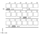
図1は、本発明の一実施の形態に係る検査システムの概略構成を示す平面図、図2は、図1における検査システムのII−II線矢視における断面図である。この検査システム100は、基板としての半導体ウエハ(以下、単に「ウエハ」と記す)Wに形成されたデバイスの電気的特性検査を行うものである。図1において、検査システム100は、複数の検査装置を備えた検査ユニット10と、ローダーユニット20と、検査ユニット10とローダーユニット20との間に設けられた搬送ユニット30と、これらの各ユニットを制御する制御部40と、を有している。
1 is a plan view showing a schematic configuration of an inspection system according to an embodiment of the present invention, and FIG. 2 is a cross-sectional view of the inspection system in FIG. The
<検査ユニット>
検査ユニット10は、デバイスの電気的特性検査を行う複数の検査部11を有している。各検査部11には、それぞれウエハ検査用インターフェース(図示せず)を備えた検査装置13が配置されている。図2に示すように、検査ユニット10は、6つの検査部11が、それぞれ上段、中段及び下段の3段に配置され、合計18の検査部11が設けられている。本実施の形態では、各検査部11において、ウエハWに形成されたデバイスの低温検査が行われる。各検査部11内は、例えば乾燥空気が導入されて低露点環境に維持されている。なお、検査ユニット10における検査部11の数や配置は、図1及び図2に例示した内容に限定されるものではない。
<Inspection unit>
The
また、検査ユニット10は、図1、図2中、X方向に移動可能な搬送ステージ15を有している。搬送ステージ15は、検査ユニット10の上段、中段及び下段のそれぞれに配置されている。搬送ステージ15を介して、各段の各検査部11に対し、未検査のウエハWの搬入及び検査済みウエハWの搬出が行われる。なお、搬送ステージ15を設けず、搬送ユニット30の搬送装置31(後述)と各検査部11との間で、直接、未検査のウエハWの搬入、及び検査済みウエハWの搬出を行ってもよい。
Further, the
<ローダーユニット>
ローダーユニット20は、検査システム100にウエハW、ウエハトレイ、プローブカード等の搬出入を行う。ローダーユニット20は、複数の搬入出ステージ21に区分されている。各搬入出ステージ21には、例えば、カセットとしてのフープFを載置できるようになっている。なお、図示は省略するが、ローダーユニット20は、ウエハWの位置合わせを行うアライメント装置や、検査後のウエハWに対して針跡検査を行う針跡検査装置などを有していてもよい。
<Loader unit>
The
<搬送ユニット>
搬送ユニット30には、ウエハWの搬送を行う搬送装置31が設けられている。搬送装置31は、図1及び図2において、X方向、Y方向及びZ方向に移動可能に構成されている。搬送装置31は、ローダーユニット20の、例えばフープFから受け取った未検査のウエハWを搬送し、検査ユニット10の搬送ステージ15に受け渡す。また、搬送装置31は、検査後のウエハWを検査ユニット10の搬送ステージ15から受け取ってローダーユニット20の、例えばフープFまで搬送する。なお、搬送装置31は、一台に限らず、複数台でもよい。
<Transport unit>
The
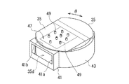
ここで、図3及び図4を参照しながら、搬送装置31の詳細な構成について説明する。図3は、搬送装置31の上部の外観構成を示す斜視図であり、図4は、搬送装置31の概略の縦断面図である。図3及び図4に示すように、搬送装置31は、例えば上下2段に配置され、ウエハWを支持する搬送アーム33A,33Bと、搬送アーム33A,33Bを覆う搬送アーム容器としてのカバー35と、これら搬送アーム33A,33B及びカバー35を同期して水平方向に回転(θ回転)させる回転駆動部37と、搬送アーム33A,33B、カバー35及び回転駆動部37を支持するベース部39と、を備えている。また、搬送装置31は、カバー35の外側に配置された枠状部材41及び遮蔽壁43を備えている。さらに、搬送装置31は、カバー35内に乾燥気体を導入する気体導入装置45を備えている。
Here, a detailed configuration of the
(搬送アーム)
一対の搬送アーム33A,33B(以下、両者を区別しない場合は、「搬送アーム33」と記すことがある)は、図示しないスライド駆動部によって、それぞれ独立して水平方向に進出及び退避が可能になされている。搬送アーム33は、進出状態で、搬送ステージ15、フープFなどの部材との間でウエハWの受け渡しを行う。搬送アーム33は、退避状態で、ウエハWをカバー35内に収容する。
(Transfer arm)
A pair of
(カバー)
カバー35は、天井部35aと、底部35bと、4つの側部35cを有している。カバー35の天井部35aには、カバー35内に乾燥気体を導入するガス導入部47Aが設けられている。また、カバー35の底部35bには、カバー35内に乾燥気体を導入するガス導入部47Bが設けられている。ガス導入部47Aは、気体導入装置45が接続される複数の導入口49Aを有している。ガス導入部47Bは、気体導入装置45が接続される複数の導入口49Bを有している。また、カバー35の一つの側部35cには、ウエハWを支持した搬送アーム33の進出及び退避を許容する開口部35dが形成されている。カバー35は、例えば金属、合成樹脂などの材質で形成することができる。また、カバー35は、複数の部材を組み合わせて形成してもよい。
(cover)
The
(回転駆動部)
回転駆動部37は、搬送アーム33及びカバー35を、水平方向に回転(θ回転)させる。回転駆動部37は、ベース部39、ベース部39に固定された枠状部材41及び遮蔽壁43は回転させず、搬送アーム33及びカバー35を水平回転させる。従って、枠状部材41及び遮蔽壁43と、搬送アーム33及びカバー35とは、回転駆動部37によって、相対的な回転位置が変化するように構成されている。
(Rotation drive part)
The
(ベース部)
ベース部39は、搬送アーム33、カバー35、回転駆動部37、枠状部材41及び遮蔽壁43を支持している。ベース部39は、図示しない駆動機構を有しており、この駆動機構によって、搬送装置31の全体がX方向、Y方向及びZ方向(図1、図2参照)に移動可能に構成されている。
(Base part)
The
(枠状部材)
枠状部材41は、ベース部39に固定された部分カバーである。枠状部材41は、搬送アーム33が挿入される開口部41aを有している。枠状部材41は、検査ユニット10の搬送ステージ15との間でウエハWの受け渡しを行う際に、ウエハWを支持した搬送アーム33が進出、退避する空間を外部から遮蔽する機能を有している。また、枠状部材41は、カバー35の外周に沿った円弧状の切欠き部分41bを有し、この切欠き部分41bが僅かな隙間を介してカバー35と隣接している。枠状部材41は、例えば金属、合成樹脂などの材質で形成することができる。
(Frame-shaped member)
The frame-shaped
(遮蔽壁)
遮蔽壁43は、ベース部39に固定されている。遮蔽壁43は、カバー35の開口部35dを、開放した状態と閉じた状態とに切り替える遮蔽部材である。搬送アーム33が搬送ステージ15、フープFなどの部材との間でウエハWの受け渡しを行う際には、遮蔽壁43は、カバー35の開口部35dと重ならない位置に配置されている。一方、搬送アーム33が特定の回転位置にあるとき、遮蔽壁43は、カバー35の開口部35dと重なり、開口部35dを遮蔽する。この点については、後で詳しく説明する。遮蔽壁43は、例えば金属、合成樹脂などの材質で形成することができる。
(Shielding wall)
The shielding
(気体導入装置)
気体導入装置45は、カバー35のガス導入部47A,47Bを介してカバー35内に乾燥気体を導入する。図4に示すように、気体導入装置45は、気体供給源51と、この気体供給源51と複数の導入口49Aとを接続する供給管53と、供給管53の途中に配設された開閉バルブ55A及び流量制御のためのマスフローコントローラ(MFC)57Aを備えている。また、気体導入装置45は、気体供給源51と、この気体供給源51と複数の導入口49Bとを接続する供給管54と、供給管54の途中に配設された開閉バルブ55B及び流量制御のためのマスフローコントローラ(MFC)57Bを備えている。気体供給源51から供給する気体としては、例えば乾燥空気、窒素ガスなどを挙げることができる。図4では、気体供給源51は、乾燥気体の代表例として乾燥空気(DRY AIR)を供給するものとしている。供給管53は、途中で複数本の分岐管53aに分岐して、各分岐管53aがそれぞれ導入口49Aに接続されている。供給管54は、途中で複数本の分岐管54aに分岐して、各分岐管54aがそれぞれ導入口49Bに接続されている。供給管53,54、分岐管53a,54aは、例えばフレキシブルな材料によって形成されていてもよい。気体導入装置45は、開閉バルブ55A,55Bによって乾燥気体の供給・停止を切り替えるとともに、マスフローコントローラ(MFC)57A,57Bによって所望の流量に調節しながら、供給管53及び供給管54から、独立してカバー35内に乾燥気体を導入することができる。
(Gas introduction device)
The
<制御部>
検査システム100の各構成部は、それぞれ制御部40に接続されて、制御部40によって制御される。制御部40は、典型的にはコンピュータである。図5は、図1に示した制御部40のハードウェア構成の一例を示している。制御部40は、主制御部101と、キーボード、マウス等の入力装置102と、プリンタ等の出力装置103と、表示装置104と、記憶装置105と、外部インターフェース106と、これらを互いに接続するバス107とを備えている。主制御部101は、CPU(中央処理装置)111、RAM(ランダムアクセスメモリ)112およびROM(リードオンリメモリ)113を有している。記憶装置105は、情報を記憶できるものであれば、その形態は問わないが、例えばハードディスク装置または光ディスク装置である。また、記憶装置105は、コンピュータ読み取り可能な記録媒体115に対して情報を記録し、また記録媒体115より情報を読み取るようになっている。記録媒体115は、情報を記憶できるものであれば、その形態は問わないが、例えばハードディスク、光ディスク、フラッシュメモリなどである。記録媒体115は、本実施の形態の検査システム100において行われる搬送方法のレシピを記録した記録媒体であってもよい。
<Control unit>
Each component of the
制御部40では、CPU111が、RAM112を作業領域として用いて、ROM113または記憶装置105に格納されたプログラムを実行することにより、本実施の形態の検査システム100において、複数のウエハWに対し、ウエハW上に形成されたデバイスに対する検査を実行できるようになっている。具体的には、制御部40は、検査システム100において、各構成部(例えば、検査装置13、搬送ステージ15、搬送装置31等)を制御する。
In the
図6は、制御部40における搬送装置31の制御に関連する機能を示す機能ブロック図である。図6に示すように、制御部40は、搬送制御部121と、回転制御部122と、アーム制御部123と、気体導入制御部124と、入出力制御部125を備えている。これらは、CPU111が、RAM112を作業領域として用いて、ROM113または記憶装置105に格納されたソフトウエア(プログラム)を実行することによって実現される。なお、制御部40は、他の機能も有しているが、ここでは説明を省略する。
FIG. 6 is a functional block diagram illustrating functions related to the control of the
(搬送制御部)
搬送制御部121は、搬送装置31のX方向、Y方向及びZ方向への移動を制御する。具体的には、搬送制御部121は、搬送装置31のベース部39の駆動機構(図示せず)に対して制御信号を送り、搬送装置31を、X方向、Y方向、Z方向に所定速度で移動させたり、所定位置で停止させたりする制御を行う。
(Transport control unit)
The
(回転制御部)
回転制御部122は、搬送装置31における搬送アーム33及びカバー35の水平方向の回転(θ回転)を制御する。具体的には、回転制御部122は、搬送装置31の回転駆動部37に対して制御信号を送り、搬送アーム33及びカバー35を、水平方向に所定の速度で回転させたり、所定の回転角度で停止させたりする制御を行う。
(Rotation control unit)
The
(アーム制御部)
アーム制御部123は、搬送装置31における搬送アーム33の進退動作を制御する。具体的には、アーム制御部123は、搬送装置31の搬送アーム33のスライド駆動部(図示せず)に対して制御信号を送り、搬送アーム33A又は搬送アーム33Bを個別に進出させたり、退避させたりする制御を行う。アーム制御部123の制御の下で、搬送アーム33は、搬送ステージ15又はフープFとの間でウエハWの受け渡しを行う。
(Arm control unit)
The
(気体導入制御部)
気体導入制御部124は、気体導入装置45によるカバー35内への乾燥気体の導入や停止を制御する。具体的には、気体導入制御部124は、開閉バルブ55A,55B及びマスフローコントローラ(MFC)57A,57Bに対して制御信号を送り、開閉バルブ55A,55Bの開閉や、マスフローコントローラ(MFC)57A,57Bによる流量調節によって、カバー35内への乾燥気体の供給/停止の切り替え、流量の切り替えなどを制御する。
(Gas introduction control unit)
The gas
入出力制御部125は、入力装置102からの入力の制御や、出力装置103に対する出力の制御や、表示装置104における表示の制御や、外部インターフェース106を介して行う外部とのデータ等の入出力の制御を行う。
The input /
<回転位置>
次に、図3、図7及び図8を参照して、搬送アーム33とカバー35の回転位置について説明する。上記のとおり、回転制御部122による制御の下で、回転駆動部37によって、搬送アーム33とカバー35は、同期して水平方向に正逆に回転(θ回転)する。図7及び図8は、図3の状態から、カバー31を、それぞれ所定角度回転させた状態を示している。図3、図7及び図8では、搬送アーム33及びカバー35が回転する方向を符号θで示している。なお、図3、図7及び図8では、外観のカバー35を示しているが、内部の搬送アーム33もカバー35と同期して回転する。
<Rotation position>
Next, the rotational positions of the
仮に、図3の状態を初期位置とすると、図7は、カバー35を初期位置から水平方向に反時計回りにθ1(例えば90度)の角度で回転させた状態を示している。また、図8は、カバー35を図7の回転位置から、さらに水平方向に、反時計回りにθ2(例えば90度)の角度で回転させた状態を示している。つまり、図8の回転位置は、図3の初期位置から水平方向にθ1+θ2(例えば180度)の角度で回転させた位置である。
If the state of FIG. 3 is the initial position, FIG. 7 shows a state in which the
図3に示す初期位置を、検査ユニット10の搬送ステージ15から、検査済みのウエハWを受け取る位置とする。本実施の形態では、この位置を第1の回転位置とする。第1の回転位置では、カバー35の開口部35dは、ベース部39に固定された枠状部材41の開口部41aと重なる位置にあり、搬送アーム33が開口部35d及び開口部41aを介して進出、退避することが可能になる。
The initial position shown in FIG. 3 is a position for receiving the inspected wafer W from the
図7に示す回転位置は、検査ユニット10の搬送ステージ15から受け取った検査済みのウエハWをローダーユニット20へ向けて搬送するときの回転位置である。本実施の形態では、この位置を、第2の回転位置とする。第2の回転位置では、ベース部39に固定された遮蔽壁43が、カバー35の開口部35dに重なることによって、開口部35dが塞がれる。そのため、カバー35内に水分を含む外気が進入し難くなり、低温の検査済みのウエハWにおいて、結露や氷結の発生が防止される。また、遮蔽壁43によって開口部35dが塞がれることで、カバー35の内部を乾燥雰囲気に保持することが容易になる。その結果、気体導入装置45からカバー35内に導入する乾燥気体の流量を抑制することもできる。このように、本実施の形態では、回転駆動部37によってθ回転動作を行うように構成されているカバー35の開口部35dを、固定された遮蔽壁43を利用して塞ぐことによって、開口部35dを塞ぐための特別の駆動機構を設ける必要がなくなり、装置構成を簡素化することができる。なお、固定された遮蔽壁43と回転するカバー35との間には、回転を妨げない程度のクリアランスが存在するため、第2の回転位置において、遮蔽壁43によってカバー35内が完全な密閉状態となるわけではない。従って、本発明において、カバー35内を「遮蔽する」、開口部35dを「塞ぐ」と言うときは、完全な気密状態を意味するものではない。
The rotation position shown in FIG. 7 is a rotation position when the inspected wafer W received from the
図8に示す回転位置は、検査済みのウエハWをローダーユニット20(例えばフープF)に受け渡すときの回転位置である。本実施の形態では、この位置を、第3の回転位置とする。第3の回転位置では、カバー35の開口部35dは、ベース部39に固定された遮蔽壁43とは重ならず、搬送アーム33が開口部35dを介して進出、退避することが可能になる。
The rotation position shown in FIG. 8 is a rotation position when the inspected wafer W is transferred to the loader unit 20 (for example, the hoop F). In the present embodiment, this position is the third rotational position. In the third rotation position, the
<搬送方法>
以上の構成を有する本実施の形態の検査システム100では、搬送装置31によって、複数の検査装置13を備えた検査ユニット10とローダーユニット20との間で、ウエハWを搬送することにより、複数枚のウエハWについて、順次デバイスの検査を行うことができる。例えば、検査システム100において、ウエハWに対する低温検査を実施する場合、本実施の形態の搬送方法は、例えば以下の第1〜第3のステップを含むことができる。
<Conveying method>
In the
(第1のステップ)
第1のステップでは、検査ユニット10から検査済みのウエハWを受け取る。すなわち、搬送装置31は、搬送アーム33及びカバー35を第1の回転位置(図3参照)にセットした状態で、検査ユニット10から検査済みのウエハWを搬送アーム33に受け取る。第1のステップでは、気体導入装置45からカバー35内に所定流量で乾燥気体を導入する。第1のステップにおいて、乾燥気体は、搬送アーム33が検査ユニット10から検査済みのウエハWを受け取る前、受け取ると同時、又は、受け取った後のいずれかのタイミングで導入を開始すればよいが、検査済みのウエハWを受け取る前にカバー35内に乾燥気体を導入しておくことが好ましい。
(First step)
In the first step, the inspected wafer W is received from the
(第2のステップ)
第2のステップでは、遮蔽壁43によってカバー35の開口部35dを遮蔽した状態で、検査ユニット10から受け取った検査済みのウエハWをローダーユニット20へ向けて搬送する。すなわち、搬送装置31は、搬送アーム33及びカバー35を第1の回転位置から第2の回転位置(図7参照)に回転させ、第2の回転位置にセットした状態で、搬送アーム33に支持されたウエハWをローダーユニット20に向けて搬送する。第2の回転位置では、遮蔽壁43によってカバー35内への外気の進入が妨げられるため、気体導入装置45からカバー35内に導入された、もしくは導入され続けている乾燥気体によって、カバー35の内部の乾燥雰囲気が確保される。つまり、特別な待機時間を設けなくても、ローダーユニット20に向けて検査済みのウエハWを搬送している間に、ウエハWを乾燥状態で昇温させることができるので、高スループットの搬送が可能になる。
(Second step)
In the second step, the inspected wafer W received from the
(第3のステップ)
第3のステップでは、検査済みのウエハWをローダーユニット20に受け渡す。すなわち、搬送装置31は、搬送アーム33及びカバー35を第2の回転位置から第3の回転位置(図8参照)に回転させ、第3の回転位置にセットした状態で、搬送アーム33に支持されたウエハWをローダーユニット20に受け渡す。
(Third step)
In the third step, the inspected wafer W is delivered to the
本実施の形態の搬送方法において、上記第1〜第3のステップは、制御部40による制御の下で行うことができる。
In the transport method of the present embodiment, the first to third steps can be performed under the control of the
<乾燥気体の流量制御>
次に、図9〜図11を参照して、本実施の形態の搬送方法における乾燥気体の流量制御について説明する。検査システム100において複数枚のウエハWに対して低温検査を実施する間は、カバー35内の雰囲気を乾燥状態に維持するため、気体導入装置45から乾燥気体を連続的に導入し続けておくことが好ましい。しかし、冷却された検査済みのウエハWを搬送アーム33によって受け取った直後においては、結露や氷結が特に発生しやすい。一方、搬送装置31で未検査のウエハWを搬送している間や、カバー35内にウエハWを収容していない状態で大量の乾燥気体を導入し続けることは合理的ではない。そのため、本実施の形態の検査システム100では、搬送アーム33によって検査済みのウエハWを受け取る前後において、カバー35内に導入する乾燥気体の流量が増加するように制御することが好ましい。なお、乾燥気体は、カバー35の天井部35aのガス導入部47A、及び底部35bのガス導入部47Bのいずれか片方又は両方を介してカバー35内に導入することが可能である。また、以下に説明する乾燥気体の流量は、ガス導入部47A及び/又はガス導入部47Bから導入される流量の合計である。
<Flow control of dry gas>
Next, with reference to FIGS. 9 to 11, the flow control of the dry gas in the transport method of the present embodiment will be described. While the low temperature inspection is performed on the plurality of wafers W in the
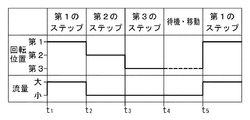
図9〜図11は、上記第1〜第3のステップにおける、搬送アーム33及びカバー35の回転位置と、気体導入装置45からカバー35内に導入される乾燥気体の流量との関係を示すタイミングチャートである。図9〜図11の横軸は時間を示し、時点t1からt2までの期間が第1のステップであり、時点t2からt3までの期間が第2のステップであり、t3からt4までの期間が第3のステップである。また、時点t1からt4までは、搬送装置31が検査ユニット10から1枚ないし2枚の検査済みのウエハWを受け取り、ローダーユニット20へ受け渡すまでの期間を意味する。さらに、時点t4からt5までの期間は、搬送装置31が検査ユニット10から新たに検査済みウエハWを受け取るまでの待機・移動の期間であり、この期間に未検査のウエハWをローダーユニット20から検査ユニット10に移送することも行われる。t5以降では、別の検査済みウエハWについて第1〜第3のステップが繰り返される。図9〜図11に示すように、搬送アーム33及びカバー35は、第1のステップでは第1の回転位置であり、第2のステップでは第2の回転位置であり、第3のステップでは第3の回転位置となる。
9 to 11 are timings showing the relationship between the rotational positions of the
図9〜図11に示す態様において、乾燥気体の流量の具体例としては、容積が約50Lのカバーに対し、流量「大」(大流量)は、100〜300L/min、好ましくは150〜250L/minの流量とすることができ、流量「小」(小流量)は、0〜80L/min、好ましくは30〜70L/minの流量とすることができる。ここで、流量が0(ゼロ)は、乾燥気体を導入しないことを意味する。図9〜図11において、例えば時点t4からt5までの待機・移動の期間(搬送装置31のカバー35内に未検査のウエハWを収容している状態も含む)には、気体導入装置45からカバー35内に導入される乾燥気体の流量を「小」とすることが、経済的観点から好ましい。
9 to 11, as a specific example of the flow rate of the dry gas, the flow rate “large” (large flow rate) is 100 to 300 L / min, preferably 150 to 250 L with respect to a cover having a volume of about 50 L. The flow rate “small” (small flow rate) can be 0 to 80 L / min, preferably 30 to 70 L / min. Here, the flow rate of 0 (zero) means that no dry gas is introduced. Figure in 9-11, for example a period of waiting and transfer from time t 4 to t 5 (including state in the
図9に示す態様では、時点t1からt4までの第1のステップから第3のステップにおいて、気体導入装置45からカバー35内に大流量で乾燥気体を導入する。ここで、第1のステップにおいて、乾燥気体は、搬送アーム33が検査ユニット10から検査済みのウエハWを受け取る前、受け取ると同時、又は、受け取った後のいずれかのタイミングで導入を開始すればよいが、検査済みのウエハWを受け取る前にカバー35内に乾燥気体を導入しておくことが好ましい。一方、時点t4からt5までの待機・移動の期間では、気体導入装置45によってカバー35内に導入する乾燥気体の流量を小流量とし、t1〜t4までの期間に比べて相対的に流量に減少させるか、もしくは停止する。このように、検査ユニット10から検査済みのウエハWを受け取る段階から、ローダーユニット20に受け渡すまでの間、気体導入装置45によってカバー35内へ大流量で乾燥気体を導入し続けることによって、カバー35内を継続的に乾燥雰囲気に保ち、搬送アーム33に支持されたウエハWにおける結露や氷結を防ぐことができる。
In the aspect shown in FIG. 9, in the first to third steps from the time point t 1 to t 4 , the dry gas is introduced into the
また、図9に示す態様では、時点t2でカバー35の回転位置を第1の回転位置から第2の回転位置に切り替えるため、時点t3までの間、遮蔽壁43によってカバー35内を密閉状態に近づけることができる。そのため、導入される乾燥気体によって、カバー35内を効果的に乾燥雰囲気に維持できる。従って、大流量の乾燥気体によって、ローダーユニット20に向けて検査済みのウエハWを搬送している間に、搬送アーム33に支持されたウエハWにおける結露や氷結を確実に防ぐことができる。また、図9に示す態様では、特別な待機時間を設けなくても、ローダーユニット20に向けて検査済みのウエハWを搬送している間に、ウエハWを乾燥状態で昇温させることができるので、高スループットの搬送が可能になる。
In the embodiment shown in FIG. 9, for switching the rotational position of the
図10に示す態様では、時点t1からt3までの第1のステップ及び第2のステップにおいて、気体導入装置45からカバー35内に大流量で乾燥気体を導入する。ここで、第1のステップにおいて、乾燥気体は、搬送アーム33が検査ユニット10から検査済みのウエハWを受け取る前、受け取ると同時、又は、受け取った後のいずれかのタイミングで導入を開始すればよいが、検査済みのウエハWを受け取る前にカバー35内に乾燥気体を導入しておくことが好ましい。一方、時点t3からt4までの第3のステップ及び時点t4からt5までの待機・移動の期間では、気体導入装置45によってカバー35内に導入する乾燥気体の流量を小流量とし、t1〜t3までの期間に比べて相対的に減少させるか、もしくは停止する。このように、検査ユニット10から検査済みのウエハWを受け取る段階から、ローダーユニット20に向けて搬送している間、気体導入装置45によってカバー35内へ大流量で乾燥気体を導入し続けることによって、カバー35内を乾燥雰囲気に保ち、搬送アーム33に支持されたウエハWにおける結露や氷結を防ぐことができる。
In the aspect shown in FIG. 10, in the first step and the second step from time t 1 to t 3 , the dry gas is introduced from the
また、図10に示す態様では、時点t2でカバー35の回転位置を第1の回転位置から第2の回転位置に切り替えるため、時点t3までの間、遮蔽壁43によってカバー35内を密閉状態に近づけることができる。そのため、時点t3まで導入される乾燥気体によって、カバー35内を効果的に乾燥雰囲気に維持できる。従って、図10に示す態様では、図9示す態様に比べ、乾燥気体の使用量を節約しながら、搬送アーム33に支持されたウエハWにおける結露や氷結を防ぐことができる。また、図10に示す態様では、特別な待機時間を設けなくても、ローダーユニット20に向けて検査済みのウエハWを搬送している間に、ウエハWを乾燥状態で昇温させることができるので、高スループットの搬送が可能になる。
In the embodiment shown in FIG. 10, for switching the rotational position of the
図11に示す態様では、時点t1からt2までの第1のステップにおいて、気体導入装置45からカバー35内に大流量で乾燥気体を導入する。ここで、第1のステップにおいて、乾燥気体は、搬送アーム33が検査ユニット10から検査済みのウエハWを受け取る前、受け取ると同時、又は、受け取った後のいずれかのタイミングで導入を開始すればよいが、検査済みのウエハWを受け取る前にカバー35内に乾燥気体を導入しておくことが好ましい。一方、時点t2からt4までの第2のステップ及び第3のステップ、並びに時点t4からt5までの待機・移動の期間では、気体導入装置45によってカバー35内に導入する乾燥気体の流量を小流量とし、t1〜t2までの期間に比べて相対的に減少させるか、停止させる。このように、検査ユニット10から検査済みのウエハWを受け取る段階で、気体導入装置45によってカバー35内へ大流量で乾燥気体を導入することによって、カバー35内を乾燥雰囲気に保ち、搬送アーム33に支持されたウエハWにおける結露や氷結を防ぐことができる。
In the aspect shown in FIG. 11, in the first step from time t 1 to time t 2 , dry gas is introduced from the
また、図11に示す態様では、時点t1からt2までの第1のステップでカバー35内に乾燥気体を導入した後、時点t2でカバー35の回転位置を第1の回転位置から第2の回転位置に切り替えるため、時点t3までの間、遮蔽壁43によってカバー35内をほぼ密閉状態に近づけることができる。そのため、時点t2で気体導入装置45からの乾燥気体の導入を減少もしくは停止しても、外気の進入が抑制されるため、カバー35内を乾燥雰囲気に維持できる。従って、図11に示す態様では、図9、図10に示す態様に比べ、乾燥気体の使用量を最小限に節約しながら、搬送アーム33に支持されたウエハWにおける結露や氷結を防ぐことができる。また、図11に示す態様では、特別な待機時間を設けなくても、ローダーユニット20に向けて検査済みのウエハWを搬送している間に、ウエハWを乾燥状態で昇温させることができるので、高スループットの搬送が可能になる。
In the embodiment shown in FIG. 11, after the introduction of the dry gas in the
以上のように、複数の検査装置13を有する本実施の形態の検査システム100では、搬送装置31による搬送のスループットを低下させることなく、ウエハWの結露や氷結を効果的に防止することができる。
As described above, in the
以上、本発明の実施の形態を例示の目的で詳細に説明したが、本発明は上記実施の形態に制約されることはなく、種々の変形が可能である。例えば、上記実施の形態では、回転駆動部37によって搬送アーム33とカバー35が同期して水平方向に回転する構成としたが、搬送アーム33とカバー35は、それぞれ独立して水平方向に回転するようにしてもよい。
As mentioned above, although embodiment of this invention was described in detail for the purpose of illustration, this invention is not restrict | limited to the said embodiment, A various deformation | transformation is possible. For example, in the above-described embodiment, the
また、上記実施の形態では、検査ユニット10は、各検査装置13で低温検査を行うことを前提に説明したが、検査ユニットの複数の検査装置13で、常温検査、低温検査、高温検査を混合して実施する場合にも、本発明を適用できる。
In the above-described embodiment, the
さらに、上記実施の形態では、カバー35に導入する乾燥気体の流量を、大流量と、停止を含む小流量との2段階で切り替える構成としたが、3段階以上の流量を切り替える構成としてもよい。
Furthermore, in the said embodiment, although it was set as the structure which switches the flow volume of the dry gas introduce | transduced into the
10…検査ユニット、11…検査部、13…検査装置、15…搬送ステージ、20…ローダーユニット、21…搬入出ステージ、30…搬送ユニット、31…搬送装置、33A,33B…搬送アーム、35…カバー、35a…天井部、35b…底部、35c…側部、35d…開口部、37…回転駆動部、39…ベース部、40…制御部、41…枠状部材、41a…開口部、43…遮蔽壁、45…気体導入装置、51…気体供給源、53,54…供給管、55A,55B…開閉バルブ、57A,57B…マスフローコントローラ(MFC)、100…検査システム、F…フープ、W…半導体ウエハ
DESCRIPTION OF
Claims (9)
前記検査システムは、
前記基板の検査を行う複数の検査装置を有する検査ユニットと、
複数の前記基板を収容するカセットを載置するローダーユニットと、
前記検査ユニットと前記ローダーユニットとの間で前記基板を搬送する搬送装置と、
を備えており、
前記搬送装置は、
前記基板を支持する水平方向に回転可能な搬送アームと、
前記搬送アームを覆うとともに、該搬送アームの進出及び退避を許容する開口部を有し、かつ、水平方向に回転可能な搬送アーム容器と、
前記開口部を、開放した状態と閉じた状態とに切り替える遮蔽部材と、
前記搬送アーム容器内に乾燥気体を導入する気体導入装置と、
を有しており、
前記検査ユニットから検査済みの前記基板を受け取る第1のステップと、
前記遮蔽部材によって前記開口部を遮蔽した状態で、前記検査ユニットから受け取った検査済みの前記基板を前記ローダーユニットへ向けて搬送する第2のステップと、
検査済みの前記基板を前記ローダーユニットに受け渡す第3のステップと、
を含むとともに、前記第1のステップでは、前記搬送アーム及び前記搬送アーム容器を第1の回転位置にセットして、前記検査ユニットから検査済みの前記基板を受け取り、
前記第2のステップでは、前記搬送アーム容器を前記第1の回転位置とは異なり、かつ前記遮蔽部材によって前記開口部が遮蔽される第2の回転位置にセットして検査済みの前記基板を搬送し、
前記第3のステップでは、前記搬送アーム及び前記搬送アーム容器を前記第1の回転位置及び前記第2の回転位置とは異なる第3の回転位置にセットして、検査済みの前記基板を前記ローダーユニットに受け渡す、ことを特徴とする搬送方法。 A transport method for transporting the substrate in an inspection system for inspecting electrical characteristics of the substrate,
The inspection system includes:
An inspection unit having a plurality of inspection devices for inspecting the substrate;
A loader unit for mounting a cassette containing a plurality of the substrates;
A transport device for transporting the substrate between the inspection unit and the loader unit;
With
The transfer device
A transfer arm that supports the substrate and is rotatable in a horizontal direction;
A transport arm container that covers the transport arm, has an opening that allows the transport arm to advance and retreat, and is rotatable in the horizontal direction;
A shielding member that switches the opening between an open state and a closed state;
A gas introduction device for introducing a dry gas into the transfer arm container;
Have
Receiving the inspected substrate from the inspection unit;
A second step of transporting the inspected substrate received from the inspection unit to the loader unit in a state where the opening is shielded by the shielding member;
A third step of delivering the inspected substrate to the loader unit;
In the first step, the transport arm and the transport arm container are set at a first rotation position, and the inspected substrate is received from the inspection unit.
In the second step, the transported arm container is set at a second rotational position different from the first rotational position and the opening is shielded by the shielding member, and the inspected substrate is transported. And
In the third step, the transport arm and the transport arm container are set at a third rotational position different from the first rotational position and the second rotational position, and the inspected substrate is loaded into the loader. Transferring to a unit .
前記検査システムは、
前記基板の検査を行う複数の検査装置を有する検査ユニットと、
複数の前記基板を収容するカセットを載置するローダーユニットと、
前記検査ユニットと前記ローダーユニットとの間で前記基板を搬送する搬送装置と、
を備えており、
前記搬送装置は、
前記基板を支持する水平方向に回転可能な搬送アームと、
前記搬送アームを覆うとともに、該搬送アームの進出及び退避を許容する開口部を有し、かつ、水平方向に回転可能な搬送アーム容器と、
前記開口部を、開放した状態と閉じた状態とに切り替える遮蔽部材と、
前記搬送アーム容器内に乾燥気体を導入する気体導入装置と、
を有しており、
前記検査ユニットから検査済みの前記基板を受け取る第1のステップと、
前記遮蔽部材によって前記開口部を遮蔽した状態で、前記検査ユニットから受け取った検査済みの前記基板を前記ローダーユニットへ向けて搬送する第2のステップと、
検査済みの前記基板を前記ローダーユニットに受け渡す第3のステップと、
を含み、
前記気体導入装置は、前記搬送アーム容器内に未検査の前記基板が収容されているとき、前記搬送アーム容器内に前記乾燥気体を導入しないか、又は第1の流量で導入するとともに、少なくとも前記第1のステップでは、前記搬送アーム容器内に、前記第1の流量よりも多い第2の流量で前記乾燥気体を導入することを特徴とする搬送方法。 A transport method for transporting the substrate in an inspection system for inspecting electrical characteristics of the substrate,
The inspection system includes:
An inspection unit having a plurality of inspection devices for inspecting the substrate;
A loader unit for mounting a cassette containing a plurality of the substrates;
A transport device for transporting the substrate between the inspection unit and the loader unit;
With
The transfer device
A transfer arm that supports the substrate and is rotatable in a horizontal direction;
A transport arm container that covers the transport arm, has an opening that allows the transport arm to advance and retreat, and is rotatable in the horizontal direction;
A shielding member that switches the opening between an open state and a closed state;
A gas introduction device for introducing a dry gas into the transfer arm container;
Have
Receiving the inspected substrate from the inspection unit;
A second step of transporting the inspected substrate received from the inspection unit to the loader unit in a state where the opening is shielded by the shielding member;
A third step of delivering the inspected substrate to the loader unit;
Including
When the uninspected substrate is accommodated in the transfer arm container, the gas introduction device does not introduce the dry gas into the transfer arm container or introduces the dry gas at a first flow rate, and at least the in a first step, the conveying method wherein the transport arm vessel, and introducing the dry gas in the first second flow greater than the flow rate.
前記基板の電気的特性の検査を行う複数の検査装置を有する検査ユニットと、
複数の前記基板を収容するカセットを載置するローダーユニットと、
前記検査ユニットと前記ローダーユニットとの間で前記基板を搬送する搬送装置と、
前記搬送装置を制御する制御部と、
を備えており、
前記搬送装置は、
前記基板を支持する水平方向に回転可能な搬送アームと、
前記搬送アームを覆うとともに、該搬送アームの進出及び退避を許容する開口部を有し、かつ、水平方向に回転可能な搬送アーム容器と、
前記開口部を、開放した状態と閉じた状態とに切り替える遮蔽部材と、
前記搬送アーム容器内に乾燥気体を導入する気体導入装置と、
を有しており、
前記制御部は、
前記搬送アーム及び前記搬送アーム容器の回転を制御する回転制御部と、
前記気体導入装置による前記乾燥気体の導入を制御する気体導入制御部と、
を有しており、
前記回転制御部は、
前記検査装置から検査済みの前記基板を受け取るときに、前記搬送アーム及び前記搬送アーム容器を第1の回転位置にセットし、
前記検査ユニットから受け取った検査済みの前記基板を前記ローダーユニットへ向けて搬送するときに、前記搬送アーム容器を前記第1の回転位置とは異なり、かつ前記遮蔽部材によって前記開口部が遮蔽される第2の回転位置にセットし、
検査済みの前記基板を前記ローダーユニットに受け渡すときに、前記搬送アーム及び前記搬送アーム容器を前記第1の回転位置及び前記第2の回転位置とは異なる第3の回転位置にセットするものであることを特徴とする検査システム。 An inspection system for inspecting electrical characteristics of a substrate,
An inspection unit having a plurality of inspection devices for inspecting the electrical characteristics of the substrate;
A loader unit for mounting a cassette containing a plurality of the substrates;
A transport device for transporting the substrate between the inspection unit and the loader unit;
A control unit for controlling the conveying device;
With
The transfer device
A transfer arm that supports the substrate and is rotatable in a horizontal direction;
A transport arm container that covers the transport arm, has an opening that allows the transport arm to advance and retreat, and is rotatable in the horizontal direction;
A shielding member that switches the opening between an open state and a closed state;
A gas introduction device for introducing a dry gas into the transfer arm container;
Have
The controller is
A rotation control unit for controlling rotation of the transfer arm and the transfer arm container;
A gas introduction controller for controlling the introduction of the dry gas by the gas introduction device;
Have
The rotation control unit
When receiving the inspected substrate from the inspection apparatus, the transfer arm and the transfer arm container are set at a first rotation position,
When the inspected substrate received from the inspection unit is transported toward the loader unit, the transport arm container is different from the first rotation position, and the opening is shielded by the shielding member. Set to the second rotational position,
When transferring the inspected substrate to the loader unit, the transfer arm and the transfer arm container are set at a third rotation position different from the first rotation position and the second rotation position. Inspection system characterized by being.
Priority Applications (5)
| Application Number | Priority Date | Filing Date | Title |
|---|---|---|---|
| JP2014198444A JP6400412B2 (en) | 2014-09-29 | 2014-09-29 | Conveying method and inspection system |
| TW104131263A TWI673505B (en) | 2014-09-29 | 2015-09-22 | Transfer method and inspection system |
| KR1020150134412A KR101813326B1 (en) | 2014-09-29 | 2015-09-23 | Transfer method and inspection system |
| CN201510633761.5A CN105470182B (en) | 2014-09-29 | 2015-09-29 | Carrying method and inspection system |
| US14/869,896 US10006961B2 (en) | 2014-09-29 | 2015-09-29 | Transfer method and inspection system |
Applications Claiming Priority (1)
| Application Number | Priority Date | Filing Date | Title |
|---|---|---|---|
| JP2014198444A JP6400412B2 (en) | 2014-09-29 | 2014-09-29 | Conveying method and inspection system |
Related Child Applications (1)
| Application Number | Title | Priority Date | Filing Date |
|---|---|---|---|
| JP2017159678A Division JP2017228789A (en) | 2017-08-22 | 2017-08-22 | Inspection system |
Publications (3)
| Publication Number | Publication Date |
|---|---|
| JP2016072356A JP2016072356A (en) | 2016-05-09 |
| JP2016072356A5 JP2016072356A5 (en) | 2017-09-28 |
| JP6400412B2 true JP6400412B2 (en) | 2018-10-03 |
Family
ID=55584124
Family Applications (1)
| Application Number | Title | Priority Date | Filing Date |
|---|---|---|---|
| JP2014198444A Active JP6400412B2 (en) | 2014-09-29 | 2014-09-29 | Conveying method and inspection system |
Country Status (5)
| Country | Link |
|---|---|
| US (1) | US10006961B2 (en) |
| JP (1) | JP6400412B2 (en) |
| KR (1) | KR101813326B1 (en) |
| CN (1) | CN105470182B (en) |
| TW (1) | TWI673505B (en) |
Families Citing this family (7)
| Publication number | Priority date | Publication date | Assignee | Title |
|---|---|---|---|---|
| JP6615698B2 (en) * | 2016-06-20 | 2019-12-04 | 東京エレクトロン株式会社 | Conveying device, conveying method, and inspection system |
| JP6655516B2 (en) * | 2016-09-23 | 2020-02-26 | 東京エレクトロン株式会社 | Board inspection equipment |
| US11097907B2 (en) | 2017-07-10 | 2021-08-24 | Tokyo Electron Limited | Substrate transfer device and substrate transfer method |
| JP6813816B2 (en) * | 2018-04-05 | 2021-01-13 | 東京エレクトロン株式会社 | Joining system and joining method |
| JP7349240B2 (en) * | 2018-10-05 | 2023-09-22 | 東京エレクトロン株式会社 | Board warehouse and board inspection method |
| JP7390934B2 (en) * | 2020-03-03 | 2023-12-04 | 東京エレクトロン株式会社 | Inspection equipment |
| CN114073832B (en) * | 2020-08-17 | 2023-02-03 | 锥能机器人嘉兴有限公司 | Locking device |
Family Cites Families (8)
| Publication number | Priority date | Publication date | Assignee | Title |
|---|---|---|---|---|
| JPH07254635A (en) * | 1994-03-15 | 1995-10-03 | Hitachi Ltd | Semiconductor producing apparatus |
| JP3783075B2 (en) | 2001-12-13 | 2006-06-07 | 東京エレクトロン株式会社 | Probe device and loader device |
| JP4832151B2 (en) * | 2006-04-25 | 2011-12-07 | 株式会社東京精密 | Probe card delivery method, prober and probe card supply / collection system |
| JP4789821B2 (en) * | 2007-02-05 | 2011-10-12 | 東京エレクトロン株式会社 | Inspection method for substrate processing apparatus |
| JP4767896B2 (en) * | 2007-03-29 | 2011-09-07 | 東京エレクトロン株式会社 | Inspected object transport device and inspection device |
| JP4959457B2 (en) * | 2007-07-26 | 2012-06-20 | 東京エレクトロン株式会社 | Substrate transport module and substrate processing system |
| JP5952645B2 (en) | 2012-06-06 | 2016-07-13 | 東京エレクトロン株式会社 | Wafer inspection interface and wafer inspection apparatus |
| JP2015115517A (en) * | 2013-12-13 | 2015-06-22 | シンフォニアテクノロジー株式会社 | Wafer transport device and efem |
-
2014
- 2014-09-29 JP JP2014198444A patent/JP6400412B2/en active Active
-
2015
- 2015-09-22 TW TW104131263A patent/TWI673505B/en active
- 2015-09-23 KR KR1020150134412A patent/KR101813326B1/en active IP Right Grant
- 2015-09-29 US US14/869,896 patent/US10006961B2/en active Active
- 2015-09-29 CN CN201510633761.5A patent/CN105470182B/en active Active
Also Published As
| Publication number | Publication date |
|---|---|
| CN105470182B (en) | 2018-07-27 |
| TW201625970A (en) | 2016-07-16 |
| CN105470182A (en) | 2016-04-06 |
| KR20160037773A (en) | 2016-04-06 |
| US20160091562A1 (en) | 2016-03-31 |
| KR101813326B1 (en) | 2017-12-28 |
| JP2016072356A (en) | 2016-05-09 |
| US10006961B2 (en) | 2018-06-26 |
| TWI673505B (en) | 2019-10-01 |
Similar Documents
| Publication | Publication Date | Title |
|---|---|---|
| JP6400412B2 (en) | Conveying method and inspection system | |
| US10403525B2 (en) | Substrate processing method and substrate processing system | |
| JP6040757B2 (en) | Positioning method of transport mechanism, method of calculating displacement amount of object to be processed, and correcting method of teaching data of transport mechanism | |
| KR20190015135A (en) | Inspection system | |
| US20080079456A1 (en) | Test handler for testing semiconductor device and method of testing semiconductor device using the same | |
| JP2008251678A (en) | Inspection subject transfer device and inspection apparatus | |
| JP2009010287A (en) | Processing system for substrate | |
| US20090087289A1 (en) | Structure for storing a substrate and semiconductor manufacturing apparatus | |
| US20090014126A1 (en) | Substrate processing apparatus and substrate processing method | |
| WO2020059574A1 (en) | Vacuum process device and substrate transporting method | |
| JP2017228789A (en) | Inspection system | |
| JP2016207767A (en) | Substrate processing system | |
| JP7137977B2 (en) | SUBSTRATE PROCESSING APPARATUS AND SUBSTRATE PROCESSING METHOD | |
| JP4757924B2 (en) | Substrate processing equipment | |
| WO2021171810A1 (en) | Substrate treatment device and substrate treatment method | |
| JP6647379B2 (en) | Inspection system | |
| US9828675B2 (en) | Processing apparatus and processing method | |
| JP6363929B2 (en) | Processing apparatus and processing method | |
| WO2020203205A1 (en) | Substrate processing system and substrate processing method | |
| JP3612265B2 (en) | Coating and developing equipment | |
| US20150253082A1 (en) | Vertical heat treatment apparatus | |
| JP4910033B2 (en) | Probe device | |
| KR102510897B1 (en) | Substrate transport device and substrate transport method | |
| JPH09330971A (en) | Substrate treating device | |
| US20230106927A1 (en) | Substrate processing apparatus and substrate processing method |
Legal Events
| Date | Code | Title | Description |
|---|---|---|---|
| A621 | Written request for application examination |
Free format text: JAPANESE INTERMEDIATE CODE: A621 Effective date: 20170809 |
|
| A521 | Request for written amendment filed |
Free format text: JAPANESE INTERMEDIATE CODE: A523 Effective date: 20170816 |
|
| A977 | Report on retrieval |
Free format text: JAPANESE INTERMEDIATE CODE: A971007 Effective date: 20180411 |
|
| A131 | Notification of reasons for refusal |
Free format text: JAPANESE INTERMEDIATE CODE: A131 Effective date: 20180418 |
|
| A521 | Request for written amendment filed |
Free format text: JAPANESE INTERMEDIATE CODE: A523 Effective date: 20180612 |
|
| TRDD | Decision of grant or rejection written | ||
| A01 | Written decision to grant a patent or to grant a registration (utility model) |
Free format text: JAPANESE INTERMEDIATE CODE: A01 Effective date: 20180814 |
|
| A61 | First payment of annual fees (during grant procedure) |
Free format text: JAPANESE INTERMEDIATE CODE: A61 Effective date: 20180905 |
|
| R150 | Certificate of patent or registration of utility model |
Ref document number: 6400412 Country of ref document: JP Free format text: JAPANESE INTERMEDIATE CODE: R150 |
|
| R250 | Receipt of annual fees |
Free format text: JAPANESE INTERMEDIATE CODE: R250 |
|
| R250 | Receipt of annual fees |
Free format text: JAPANESE INTERMEDIATE CODE: R250 |
|
| R250 | Receipt of annual fees |
Free format text: JAPANESE INTERMEDIATE CODE: R250 |
|
| R250 | Receipt of annual fees |
Free format text: JAPANESE INTERMEDIATE CODE: R250 |