JP6397917B2 - Hair clipping device - Google Patents
Hair clipping device Download PDFInfo
- Publication number
- JP6397917B2 JP6397917B2 JP2016537219A JP2016537219A JP6397917B2 JP 6397917 B2 JP6397917 B2 JP 6397917B2 JP 2016537219 A JP2016537219 A JP 2016537219A JP 2016537219 A JP2016537219 A JP 2016537219A JP 6397917 B2 JP6397917 B2 JP 6397917B2
- Authority
- JP
- Japan
- Prior art keywords
- housing
- comb
- hair
- attachment
- clipping device
- Prior art date
- Legal status (The legal status is an assumption and is not a legal conclusion. Google has not performed a legal analysis and makes no representation as to the accuracy of the status listed.)
- Active
Links
Images


Classifications
-
- B—PERFORMING OPERATIONS; TRANSPORTING
- B26—HAND CUTTING TOOLS; CUTTING; SEVERING
- B26B—HAND-HELD CUTTING TOOLS NOT OTHERWISE PROVIDED FOR
- B26B19/00—Clippers or shavers operating with a plurality of cutting edges, e.g. hair clippers, dry shavers
- B26B19/20—Clippers or shavers operating with a plurality of cutting edges, e.g. hair clippers, dry shavers with provision for shearing hair of preselected or variable length
-
- B—PERFORMING OPERATIONS; TRANSPORTING
- B26—HAND CUTTING TOOLS; CUTTING; SEVERING
- B26B—HAND-HELD CUTTING TOOLS NOT OTHERWISE PROVIDED FOR
- B26B19/00—Clippers or shavers operating with a plurality of cutting edges, e.g. hair clippers, dry shavers
- B26B19/02—Clippers or shavers operating with a plurality of cutting edges, e.g. hair clippers, dry shavers of the reciprocating-cutter type
- B26B19/04—Cutting heads therefor; Cutters therefor; Securing equipment thereof
- B26B19/06—Cutting heads therefor; Cutters therefor; Securing equipment thereof involving co-operating cutting elements both of which have shearing teeth
Landscapes
- Life Sciences & Earth Sciences (AREA)
- Forests & Forestry (AREA)
- Engineering & Computer Science (AREA)
- Mechanical Engineering (AREA)
- Dry Shavers And Clippers (AREA)
- Scissors And Nippers (AREA)
Description
本発明はヘアクリッピング装置(hair clipping
device)に関し、具体的には、毛切断の長さを可変に調節するように構成されるコームアタッチメント(櫛アタッチメント)を備えるヘアクリッピング装置に関する。
The present invention is a hair clipping device.
device), and in particular, to a hair clipping device with a comb attachment configured to variably adjust the length of hair cutting.
電気毛切断器具が一般的に知られており、幹線供給される電気によって給電されるにしろ、電池によって給電されるにしろ、トリマ(trimmer)、クリッパ(clipper)、及びシェーバ(shaver)を含む。そのような装置は、人が手入れの行き届いた外観を有することを可能にするよう、体毛、特に、顔の毛及び頭髪を刈り込むために用いられる。 Electrohair cutting devices are generally known and include trimmers, clippers, and shaver, whether powered by mains-supplied electricity or powered by batteries. . Such devices are used to trim body hair, particularly facial hair and head hair, to allow a person to have a well-groomed appearance.
一般的には、毛を切断するための従来的な装置は、前方端又は切断端(遠位端とも呼ぶ)と反対側のハンドル端とを有する細長いハウジングを形成する本体を含む。切断アセンブリが遠位端に配置される。切断アセンブリは、通常、静止切断ブレードと、静止切断ブレードに対して往復式に動く可動切断ブレードとを含む。切断アセンブリの向きがヘアクリッピング装置のハウジング又は本体を方向付ける使用者によって決定されるよう、切断アセンブリは、ヘアクリッパのハウジングに対して単一の位置において固定されるのが普通である。切断歯の先端が常に使用者に見えるように、切断アセンブリの(静止切断ブレード及び可動切断ブレードの)切断歯の先端は、ヘアクリッパハウジングの正面側から突出するのが普通である。これは正にどこで毛が切断されるのかを使用者が見るのをより容易にし、それは精巧な毛輪郭を形成し且つ創り出すためにヘアクリッパを用いるときに特に有利である。 In general, conventional devices for cutting hair include a body that forms an elongated housing having a forward or cutting end (also referred to as a distal end) and an opposite handle end. A cutting assembly is disposed at the distal end. The cutting assembly typically includes a stationary cutting blade and a movable cutting blade that moves reciprocally relative to the stationary cutting blade. The cutting assembly is typically fixed in a single position relative to the hair clipper housing so that the orientation of the cutting assembly is determined by the user directing the housing or body of the hair clipping device. The cutting tooth tip (of the stationary cutting blade and the movable cutting blade) of the cutting assembly usually protrudes from the front side of the hair clipper housing so that the cutting tooth tip is always visible to the user. This makes it easier for the user to see exactly where the hair is cut, which is particularly advantageous when using hair clippers to create and create elaborate hair profiles.
異なる毛切断長さのために用いられるべき可能性をもたらすヘアクリッピング装置についての大きな使用者要求があるので、多くの既知のヘアクリッピング装置は、別個の異なる大きさのコームアタッチメントを利用する。これらのコームアタッチメントは、一般的には、切断アセンブリを皮膚に対して位置付けるために従来的なヘアクリッピング装置の遠位端に取り付けられる。換言すれば、そのようなコームアタッチメントは、皮膚の上を移動して毛を切断アセンブリに向かって案内するガイドとして用いられる。典型的には、これらのコームアタッチメントは、切断アセンブリの上に取り付けられ、毛が伸びる皮膚の表面から切断ブレードを離間させる。しかしながら、毛切断長さが変更されるときにコームアタッチメントを異なるものと常に交換しなければならないことは、使用者にとって面倒なことがある。なぜならば、これは時間がかかるのみならず、使用者は複数の異なる大きさのコームアタッチメントを用意しておかなければならないからでもある。 Many known hair clipping devices utilize separate and different sized comb attachments because there is a great user demand for hair clipping devices that provide the potential to be used for different hair cutting lengths. These comb attachments are typically attached to the distal end of a conventional hair clipping device to position the cutting assembly relative to the skin. In other words, such a comb attachment is used as a guide to move over the skin and guide the hair towards the cutting assembly. Typically, these comb attachments are mounted on a cutting assembly to separate the cutting blade from the surface of the skin from which the hair extends. However, it may be cumbersome for the user to always replace the comb attachment with a different one when the hair cutting length is changed. This is not only time consuming, but also because the user must have several differently sized comb attachments.
従って、多くの従来技術のヘアクリッピング装置は、ヘアクリッパハウジングに対する異なる位置において調節可能である1つのコームアタッチメントだけを使用する。よって、使用者は異なる毛切断長さをもたらす異なる位置の間でコームアタッチメントをシフトさせてよい。通常、これらの可動コームアタッチメントは、3mm、5mm、7mm、9mm、通常10mmまでの毛切断長さの間で調節させられてよい。 Thus, many prior art hair clipping devices use only one comb attachment that is adjustable at different positions relative to the hair clipper housing. Thus, the user may shift the comb attachment between different positions that result in different hair cutting lengths. Typically, these movable comb attachments may be adjusted between 3 mm, 5 mm, 7 mm, 9 mm, and typically a hair cutting length of up to 10 mm.
コームアタッチメントとの組み合わせにおいてヘアクリッパを用いるときに起こる主要な問題の1つは、いわゆる目詰まり効果(clogging effect)である。この目詰まり効果は、静止的なコームについて並びに調節可能な/移動可能なコームについて起こる。目詰まり効果は、ハウジングとコーム歯(櫛歯)との間に捕らえられて詰まるようになる既に切断された毛の蓄積(accumulation)に起因する。毛がひとたびハウジングとコーム歯との間に絡まると、それらはますます多くの切断された毛を集め始め、それは最終的に既に切断された毛の蓄積(built-up)を引き起こし、消費者によって目詰まりとして知覚される。これはもちろん正確な毛切断を妨げ、切断アセンブリを動かなくし且つ/或いは損傷させる閉塞(blockage)さえも引き起こすことがある。 One of the main problems that arise when using hair clippers in combination with comb attachments is the so-called clogging effect. This clogging effect occurs for stationary combs as well as for adjustable / movable combs. The clogging effect is due to the accumulation of already cut hair that becomes trapped between the housing and the comb teeth and becomes clogged. Once the hair is entangled between the housing and the comb teeth, they begin to collect more and more cut hair, which eventually causes built-up of already cut hair, Perceived as clogging. This of course prevents accurate hair cutting and can even cause blockage that may cause the cutting assembly to move and / or be damaged.
DE3441060A1は、そのような目詰まり効果を防止するために特に設計されたコームアタッチメントを備えるヘアクリッパを開示している。そこに示されるコームアタッチメントは、コーム歯の上面に配置される複数の棘付きフックを含む。これらの棘付きフックは、既に切断された毛が切断アセンブリの歯先端に戻るのを防止し且つエアクリッパハウジングとコームアタッチメントとの間に詰まるようになるのを防止する封鎖(blockade)として作用する。 DE 34410060 A1 discloses a hair clipper with a comb attachment specifically designed to prevent such clogging effects. The comb attachment shown therein includes a plurality of barbed hooks disposed on the upper surface of the comb teeth. These barbed hooks act as a blockade that prevents hair that has already been cut from returning to the tooth tip of the cutting assembly and from becoming clogged between the air clipper housing and the comb attachment. .
DE4039681A1は、主切断アセンブリと追加的なトリミングユニット(trimming unit)とを備えるヘアクリッパを開示している。 DE 4039681A1 discloses a hair clipper comprising a main cutting assembly and an additional trimming unit.
しかしながら、改良の余地が依然としてあり、特に目詰まり効果を効率的な方法において防止する余地が依然としてある。 However, there is still room for improvement, in particular room for preventing clogging effects in an efficient manner.
上述の問題を克服するヘアクリッピング装置を提供することが本発明の目的である。具体的には、ヘアクリッピング装置のハウジングとハウジングに取り付けられるコームアタッチメントとの間の切断された毛の蓄積を防止する改良されたヘアクリッピング装置を提供することが目的である。更に、使用者のために切断アセンブリの先端の視認性を増大させると同時に上述した望ましくない目詰まり効果を防止するためにコームアタッチメントの下に捕らえられ得る毛の量を最小限化することが目的である。 It is an object of the present invention to provide a hair clipping device that overcomes the above-mentioned problems. In particular, it is an object to provide an improved hair clipping device that prevents the accumulation of cut hair between the housing of the hair clipping device and the comb attachment attached to the housing. A further object is to minimize the amount of hair that can be trapped under the comb attachment to increase the visibility of the cutting assembly tip for the user while at the same time preventing the undesirable clogging effects described above. It is.
この問題は、
− ハウジングと、
− ハウジングの遠位端に配置され且つ静止切断ブレードと可動切断ブレードとを含む切断アセンブリと、
− ハウジングに解放可能に取り付け可能であり且つ複数のコーム歯を含むコームアタッチメントとを含み、
− ハウジングの正面側(front side)が、遠位端及び切断アセンブリに対して横断方向に走り、互いに平行に走る複数の隣接するリブ及び凹部を備える波形表面を含み、
− コーム歯の正面側が、ハウジングから離れる方向に面し、コーム歯の反対側の背面側(backside)が、コームアタッチメントがハウジングに取り付けられるときに波形表面と接触する、
ヘアクリッピング装置によって解決される。
This problem,
-A housing;
A cutting assembly disposed at the distal end of the housing and including a stationary cutting blade and a movable cutting blade;
-A comb attachment releasably attachable to the housing and comprising a plurality of comb teeth;
-The front side of the housing comprises a corrugated surface comprising a plurality of adjacent ribs and recesses running transverse to the distal end and the cutting assembly and running parallel to each other;
-The front side of the comb teeth faces away from the housing and the backside opposite the comb teeth contacts the corrugated surface when the comb attachment is attached to the housing;
Solved by hair clipping device.
本発明の好適な実施態様は、従属項に定められる。請求するヘアクリッピング装置は、請求するヘアクリッピング装置と類似の及び/又は同一の並びに従属項に定められるものと類似の及び/又は同一の好適な実施態様を有することが理解されるべきである。 Preferred embodiments of the invention are defined in the dependent claims. It is to be understood that the claimed hair clipping device has a preferred embodiment similar and / or identical to the claimed hair clipping device and similar and / or identical to that defined in the dependent claims.
提示するヘアクリッパ及びコームアタッチメントは、コーム歯の背面側がヘアクリッパハウジングの正面側と接触するように構成される。従って、既知の装置とは対照的に、コームアタッチメントの背面側とコームアタッチメントが取り付けられるハウジングの正面側との間には間隙がない。既に切断された毛はコームアタッチメントの背面側とハウジングの正面側との間に捕えられるようにならないことがある。よって、既に切断された毛がヘアクリッパのハウジングとコーム歯との間に集められるようになる可能性は低い。これはコーム歯の間の並びにハウジングとコーム歯の背面側との間の切断された毛の目詰まりを効率的に防止する。 The presented hair clipper and comb attachment are configured such that the back side of the comb teeth contacts the front side of the hair clipper housing. Thus, in contrast to known devices, there is no gap between the back side of the comb attachment and the front side of the housing to which the comb attachment is attached. Already cut hair may not become trapped between the back side of the comb attachment and the front side of the housing. Thus, it is unlikely that already cut hair will be collected between the hair clipper housing and the comb teeth. This effectively prevents clogging of the cut hair between the comb teeth and between the housing and the back side of the comb teeth.
コームアタッチメントの背面側とハウジングの正面側との間のこの接触の故に、既に切断された毛の輸送も改良される。切断された毛は、コームアタッチメントとハウジングとの間に絡まるようになる可能性を有することなく、コーム歯の間でコームアタッチメントから自動的に押し出される。切断された毛はこれらの2つの部品の間にもはや捕らえられるようにならないので、毛切断は改良され、それはより均一な毛切断をもたらす。 Because of this contact between the back side of the comb attachment and the front side of the housing, the transport of already cut hair is also improved. The cut hair is automatically pushed out of the comb attachment between the comb teeth without the possibility of becoming entangled between the comb attachment and the housing. Since the cut hair is no longer captured between these two parts, the hair cut is improved, which results in a more uniform hair cut.
提示するヘアクリッピング装置の主要な構成の1つは、ヘアクリッパハウジングの正面側に配置される波形表面である。前記波形表面は、互いに平行に走る複数の隣接するリブ及び凹部を含む。これらのリブ及び凹部は、ハウジングの長手方向と実質的に平行に走るのが好ましい。波形表面は、コームアタッチメントがヘアクリッパハウジングと直接的に接触するようになるのを可能にする。ここにおいて提供されるリブ及び凹部は、主に2つの利点を有する。 One of the main configurations of the presented hair clipping device is a corrugated surface located on the front side of the hair clipper housing. The corrugated surface includes a plurality of adjacent ribs and recesses that run parallel to each other. These ribs and recesses preferably run substantially parallel to the longitudinal direction of the housing. The corrugated surface allows the comb attachment to come into direct contact with the hair clipper housing. The ribs and recesses provided here have two main advantages.
一方では、凹部は、コーム歯の背面側を少なくとも部分的に受け入れるための受入れスロットとして機能してよい。従って、コームアタッチメントがハウジングに対してより一層近接して配置されるように、コーム歯はハウジング内に少なくとも部分的に凹まされてよい。以下に更に説明するように、これは望ましくない目詰まり効果を防止するのみならず、コーム歯の剛性も増大させる。 On the one hand, the recess may function as a receiving slot for at least partially receiving the back side of the comb teeth. Thus, the comb teeth may be at least partially recessed in the housing such that the comb attachment is positioned closer to the housing. As will be explained further below, this not only prevents unwanted clogging effects, but also increases the stiffness of the comb teeth.
他方では、コームアタッチメントのコーム歯の背面側がハウジングの正面側に触れるとしても、リブは使用者が切断アセンブリの切断歯の先端を依然として見ることを可能にする。この場合、使用者はリブの間に設けられる凹部を通じて切断アセンブリの切断歯の先端を依然として見てよく、それは正確な毛輪郭取り(contouring)のためにコームアタッチメントを備えないヘアクリッパを用いるときに特に有利である。これは以下に更に提供する説明によって明らかになる。 On the other hand, even if the back side of the comb teeth of the comb attachment touches the front side of the housing, the ribs still allow the user to see the tip of the cutting teeth of the cutting assembly. In this case, the user may still see the cutting tooth tip of the cutting assembly through the recess provided between the ribs, especially when using a hair clipper without a comb attachment for accurate hair contouring. It is advantageous. This will become apparent from the description provided further below.
従って、実施態様に依存して、コームアタッチメントのコーム歯の背面側は、リブの上面(top surface)と接触するか或いは凹部の地面(ground)と接触する。「リブ」及び「凹部」という用語は相対的な用語であると理解されるべきであることが留意されるべきである。凹部はリブの頂端に関して(対して)凹まされる。そのようなリブ及び凹部は、スロットが凹部を形成し且つスロットの間の空間がリブを形成するように平坦な表面に平行なスロットを設けることによって或いはリブが平坦な表面から突出し且つリブの間の空間が凹部を形成するように平坦な表面にリブを設けることによって創り出されてよい。いずれにしても、各リブは2つの凹部に隣接し、各凹部は2つのリブに隣接する、即ち、リブ及び凹部は、交互(リブ−凹部−リブ−凹部等)に互いに平行に配置される。 Thus, depending on the embodiment, the back side of the comb teeth of the comb attachment contacts the top surface of the rib or the ground of the recess. It should be noted that the terms “rib” and “recess” are to be understood as relative terms. The recess is recessed with respect to the top end of the rib. Such ribs and recesses can be formed by providing slots parallel to the flat surface such that the slots form recesses and the spaces between the slots form ribs, or the ribs protrude from the flat surface and between the ribs. This space may be created by providing ribs on a flat surface so that a recess is formed. In any case, each rib is adjacent to two recesses, and each recess is adjacent to two ribs, i.e., the ribs and recesses are arranged alternately (rib-depression-rib-depression etc.) parallel to each other. .
本発明の好適な実施態様において、ヘアクリッピング装置は、リブ及び凹部の長手方向に沿ってハウジングに対するコームアタッチメントの位置を調節する調節機構を更に含む。 In a preferred embodiment of the present invention, the hair clipping device further includes an adjustment mechanism for adjusting the position of the comb attachment relative to the housing along the length of the ribs and recesses.
これは、使用者の必要に応じた長さ設定が調節可能なヘアクリッピング装置上の単一のコームアタッチメントを有することを可能にする。調節機構は、1mmから開始して21mmまで長さ設定を調節することを可能にするのが好ましい。調節機構は、所定の段階、例えば、1ミリメートルの段階における長さ設定を可能にするように構成されてよく、或いは、例えば、1〜21mmの全範囲に亘る無段式の設定を可能にするよう構成されてよい。 This makes it possible to have a single comb attachment on the hair clipping device with adjustable length settings according to the user's needs. The adjustment mechanism preferably allows to adjust the length setting starting from 1 mm to 21 mm. The adjustment mechanism may be configured to allow length setting at a predetermined stage, eg, 1 millimeter stage, or, for example, allow stepless setting over the entire range of 1-21 mm. May be configured as follows.
調節機構は、コームアタッチメントに配置される2つの対応する案内レールと係合するヘアクリッパハウジングの正面側に設けられる2つの案内レールによって実現されてよい。しかしながら、案内レールはハウジングの側方側に設けられてもよい。同様に、調節機構をラチェット式の案内レールとして実現することも可能である。 The adjustment mechanism may be realized by two guide rails provided on the front side of the hair clipper housing that engage with two corresponding guide rails arranged on the comb attachment. However, the guide rail may be provided on the side of the housing. Similarly, the adjustment mechanism can be realized as a ratchet guide rail.
好適な実施態様によれば、調節機構はコームアタッチメントをハウジングに対する複数の異なる位置に設定するように構成され、コーム歯の背面側は複数の位置の各々において波形表面と接触する。 According to a preferred embodiment, the adjustment mechanism is configured to set the comb attachment at a plurality of different positions relative to the housing, the back side of the comb teeth contacting the corrugated surface at each of the plurality of positions.
換言すれば、これは、長さ設定とは無関係に、コーム歯の背面側がハウジングの正面側に設けられる波形表面に常に触れることを意味する。長さ設定を変更する間に、コームアタッチメントの背面側はクリッパハウジングの正面側の波形表面の上を常に摺動し、全範囲に亘る平行な動きにおいてリブ及び凹部の長手方向に沿って動く。結果的に、全ての長さ設定について、毛がヘアクリッパのハウジングとコームアタッチメントとの間に絡まるようになることが防止される。 In other words, this means that the back side of the comb teeth always touches the corrugated surface provided on the front side of the housing, regardless of the length setting. While changing the length setting, the back side of the comb attachment always slides over the corrugated surface on the front side of the clipper housing and moves along the longitudinal direction of the ribs and recesses in parallel motion over the entire range. As a result, for all length settings, hair is prevented from becoming tangled between the hair clipper housing and the comb attachment.
更なる実施態様によれば、コームアタッチメントがハウジングに取り付けられるときに、コームアタッチメントのコーム歯はリブ及び凹部と平行に走る。従って、コームアタッチメントがハウジングに取り付けられるときでさえも、切断アセンブリの切断歯の先端は依然として見える。更に、この構成はコームとハウジングとの間の接続の安定性を増大させる。なぜならば、各コーム歯の背面側はリブの上方側(upper side)又は凹部の地面と接触するからである。コーム歯の背面側とハウジングの正面側の波形表面との間のこの接触は、特定の地点での接触であるのみならず、それぞれの各コーム歯とリブ又は凹部との間の少なくとも線接触でもある。 According to a further embodiment, when the comb attachment is attached to the housing, the comb teeth of the comb attachment run parallel to the ribs and recesses. Thus, even when the comb attachment is attached to the housing, the cutting tooth tip of the cutting assembly is still visible. In addition, this configuration increases the stability of the connection between the comb and the housing. This is because the back side of each comb tooth contacts the upper side of the rib or the ground of the recess. This contact between the back side of the comb teeth and the corrugated surface on the front side of the housing is not only a contact at a specific point, but also at least a line contact between each respective comb tooth and a rib or recess. is there.
更なる好適な実施態様によれば、各コーム歯の背面側が凹部のうちのそれぞれの凹部のベース(base)と接触するよう、コームアタッチメントのコーム歯は、コームアタッチメントがハウジングに取り付けられるときに、凹部内に少なくとも部分的に受け入れられる。これは互いに離間する個々のコーム歯の剛性(stiffness)を更に向上させる。なぜならば、各コーム歯はハウジング内に固定され且つハウジングによって支持されるからである。コーム歯の剛性の向上は特に有利である。なぜならば、それは均一な毛切断を創り出すのを可能にするからである。コームアタッチメントを使用者の頭に押し付ける力の故に、コーム歯がハウジングから離れる方向に曲がるとしても、ヘアクリッパハウジングの正面側とコームアタッチメントの背面側との間の間隙は閉じたままである。なぜならば、この場合、コーム歯は提供される凹部内にも少なくとも部分的に受け入れられるからである。この実施態様における凹部は、いわば受入れスロットとして機能し、各凹部は、コームアタッチメントのコーム歯のうちの1つを受け入れる。従って、望ましくない目詰まり効果は効果的に防止される。 According to a further preferred embodiment, when the comb attachment is attached to the housing, the comb teeth of the comb attachment are such that the back side of each comb tooth contacts the base of the respective one of the recesses. At least partially received within the recess. This further improves the stiffness of the individual comb teeth that are spaced apart from each other. This is because each comb tooth is fixed in and supported by the housing. Increasing the rigidity of the comb teeth is particularly advantageous. Because it makes it possible to create a uniform hair cut. Because of the force pressing the comb attachment against the user's head, the gap between the front side of the hair clipper housing and the back side of the comb attachment remains closed even if the comb teeth bend away from the housing. This is because in this case the comb teeth are also at least partially received in the provided recesses. The recesses in this embodiment function as so-called receiving slots, each recess receiving one of the comb teeth of the comb attachment. Thus, undesirable clogging effects are effectively prevented.
更なる好適な実施態様によれば、コームアタッチメントのコーム歯の各々は、凹部の幅と実質的に等しい幅を有する。前記幅はコーム歯及び凹部の長手方向に対して垂直に測定されるコーム歯及び凹部の横方向寸法を示すことが留意されるべきである。 According to a further preferred embodiment, each of the comb teeth of the comb attachment has a width substantially equal to the width of the recess. It should be noted that the width indicates the lateral dimension of the comb teeth and recesses measured perpendicular to the longitudinal direction of the comb teeth and recesses.
コーム歯の幅が凹部の幅に適合されるならば、コームアタッチメントとヘアクリッパハウジングとの間のインターフェースの安定性は更に改良される。目詰まりの量の低下の次に、各個々のコーム歯の剛性は、ハウジングの案内及び支持の故に、各コーム歯に対して垂直な方向において向上させられる。この剛性の向上は、均一な毛切断やコームアタッチメント及びヘアクリッピングユニットのより強固な品質の知覚をもたらす。ハウジングの波形表面の凹部内でのコーム歯の受入れの故に、コーム歯はもはやそれほど側方に撓まないことがある。よって、切断された毛がコーム歯とハウジングの正面側との間に集められるようになる可能性は、より一層効果的に防止される。 If the width of the comb teeth is adapted to the width of the recess, the stability of the interface between the comb attachment and the hair clipper housing is further improved. Following a reduction in the amount of clogging, the stiffness of each individual comb tooth is improved in a direction perpendicular to each comb tooth due to the guidance and support of the housing. This increased stiffness results in a more solid quality perception of uniform hair cutting and comb attachment and hair clipping units. Due to the receipt of the comb teeth within the recesses in the corrugated surface of the housing, the comb teeth may no longer bend sideways as much. Thus, the possibility that the cut hair is collected between the comb teeth and the front side of the housing is prevented more effectively.
上述の剛化構成は、ハウジングの正面側から突出するリブを有することによって実現されるのが好ましい。このようにして、凹部はリブの間に形成され、各凹部は、コーム歯の側面と接触し且つそれらを安定させる2つの横方向フランクを有する。 The stiffening configuration described above is preferably realized by having ribs protruding from the front side of the housing. In this way, recesses are formed between the ribs, each recess having two lateral flank that contact and stabilize the sides of the comb teeth.
本発明の他の実施態様では、コームアタッチメントがハウジングに取り付けられるとき、各コーム歯の背面側はリブのうちのそれぞれのリブの上方側と接触する。 In another embodiment of the invention, when the comb attachment is attached to the housing, the back side of each comb tooth contacts the upper side of each of the ribs.
上述の第1の実施態様とは対照的に、コーム歯の背面側は、ヘアクリッパハウジングの正面側にある波形表面の凹部内に凹まされる代わりに、リブの上方側と接触する。この場合、コームアタッチメントのコーム歯の各々は、リブの幅と実質的に等しい或いはリブの幅を超える幅を有するのが好ましい。再び、前記幅はリブの長手方向に対して垂直に測定される寸法を示す。目詰まり防止に加えて、前記実施態様は切断アセンブリの切断歯の先端が常に使用者に見えるという利点をもたらす。なぜならば、コームアタッチメントがヘアクリッパのハウジングに取り付けられているときでさえも、使用者は、凹部を通じて見ることによって、前記切断歯先端を見ることができるからである。その場合、コーム歯はリブの頂端と接触するのに対し、コーム歯の間の空間は、使用者がコームアタッチメントのコーム歯の間の空間を通じて切断アセンブリの先端を見てよいように、凹部と平行に走る。この視認性の改良は、設計問題であるのみならず、使用者のために毛切断を容易化もする。なぜならば、使用者は切断アセンブリの切断歯が彼/彼女の頭に対してどのように方向付けられるかを正確に見るからである。 In contrast to the first embodiment described above, the back side of the comb teeth contacts the upper side of the rib instead of being recessed in a corrugated surface recess on the front side of the hair clipper housing. In this case, each of the comb teeth of the comb attachment preferably has a width that is substantially equal to or exceeds the width of the rib. Again, the width indicates a dimension measured perpendicular to the longitudinal direction of the rib. In addition to preventing clogging, the embodiment provides the advantage that the cutting tooth tip of the cutting assembly is always visible to the user. This is because even when the comb attachment is attached to the housing of the hair clipper, the user can see the cutting tooth tip by looking through the recess. In that case, the comb teeth come into contact with the top end of the ribs, whereas the space between the comb teeth is recessed and recessed so that the user can see the tip of the cutting assembly through the space between the comb teeth of the comb attachment. Run in parallel. This improved visibility is not only a design issue, but also facilitates hair cutting for the user. This is because the user sees exactly how the cutting teeth of the cutting assembly are oriented relative to his / her head.
上述の実施態様によれば、静止切断ブレードは、複数の切断歯を含み、リブの各々は、ハウジングから離れる方向に面する上方側を含み、前記上方側が配置される仮想平面が、静止切断ブレードの切断歯の先端と接触する。 According to the above-described embodiment, the stationary cutting blade includes a plurality of cutting teeth, each of the ribs includes an upper side facing away from the housing, and the virtual plane on which the upper side is disposed is the stationary cutting blade In contact with the tip of the cutting tooth.
前記仮想平面は、例示的な目的のためにここに記載されるに過ぎない。上述の構成は、換言すれば、切断アセンブリの切断歯の先端がリブの上方側又は頂端(apex)と同じレベルにあることを意味する。これは、コームアタッチメントがトリマハウジングに取り付けられるときに、コームアタッチメントが切断アセンブリと接触せず、コーム歯の背面側がリブの上方側又は頂端と接触することを再び意味する。従って、リブは切断された毛がハウジングの正面側とコームアタッチメントとの間に入る入口を閉鎖する。他方、切断アセンブリの切断歯は依然として使用者に見える。なぜならば、リブの間の空間は、切断歯の先端に対して凹まされているからである。従って、コーム歯と接触しないハウジングの正面側の波形表面の部分(即ち、凹部)は引っ込められ、切断アセンブリの切断歯の先端と同じレベルにない。 The virtual plane is only described here for exemplary purposes. In other words, the above-described configuration means that the cutting tooth tip of the cutting assembly is at the same level as the upper side or apex of the rib. This again means that when the comb attachment is attached to the trimmer housing, the comb attachment does not contact the cutting assembly and the back side of the comb teeth contacts the upper side or the top end of the rib. Thus, the rib closes the entrance where the cut hair enters between the front side of the housing and the comb attachment. On the other hand, the cutting teeth of the cutting assembly are still visible to the user. This is because the space between the ribs is recessed with respect to the tip of the cutting tooth. Accordingly, the portion of the corrugated surface on the front side of the housing that is not in contact with the comb teeth (i.e., the recess) is retracted and not at the same level as the cutting tooth tip of the cutting assembly.
この実施態様は、精巧な輪郭のために毛切断の精度を増大させると同時に、上述の目詰まり効果を防止することを試みるという、矛盾する要求を解決する。 This embodiment solves the conflicting requirement of trying to prevent the clogging effect described above while at the same time increasing the accuracy of hair cutting due to the fine contours.
しかしながら、ヘアクリッパハウジングの正面側の波形表面を用いるならば、この矛盾は解決される。コーム歯は目詰まりを防止するために前記波形表面のリブと接触してよいのに対し、切断ブレードの先端はリブの間に設けられる凹部の故に依然として見える。この有意な利点は、以下に更に提供する図面及び付随する記述からより一層明らかになるであろう。 However, this inconsistency is resolved if a corrugated surface on the front side of the hair clipper housing is used. The comb teeth may contact the corrugated surface ribs to prevent clogging, while the tip of the cutting blade is still visible due to the recesses provided between the ribs. This significant advantage will become more apparent from the drawings and accompanying descriptions provided further below.
本発明の更なる実施態様によれば、コームアタッチメントは、1つのアームがコームアタッチメントの各側方側にある、2つのアームを含み、2つのアームは、コームアタッチメントがハウジングに取り付けられるときに、2つのアームがハウジングの遠位端と重なり合うように、コームアタッチメントの背面側から突出し、2つのアームの間の空間は、開放されたままにされる。 According to a further embodiment of the invention, the comb attachment includes two arms, one arm on each side of the comb attachment, the two arms when the comb attachment is attached to the housing Projecting from the back side of the comb attachment so that the two arms overlap the distal end of the housing, the space between the two arms is left open.
この実施態様では、普通はヘアクリッパハウジングの遠位端を覆うコームの側に開放空間が創り出される。2つのアームの間の前記開放空間は、(切断された毛が詰まらないよう)切断された毛が落ちて、切断し残された毛が切断性能に否定的な影響を与えないことを可能にする。これは切断効率を更に向上させる。このようにして、切断されなかった毛はコームからの自由な毛の流れを有する。なぜならば、コームの底側は2つのアームの間で開放しているからである。特により長い毛を切断するときに、これは、さもなければ切断された後に落ちるときにコームアタッチメントの底側に絡まるようになり得る切断されなかった毛を巧みに処理することなく、自由な毛の流れを創り出している。 In this embodiment, an open space is created on the side of the comb that normally covers the distal end of the hair clipper housing. The open space between the two arms allows the cut hair to fall (so that the cut hair does not get clogged) and the hair left after cutting has no negative impact on the cutting performance To do. This further improves the cutting efficiency. In this way, the uncut hair has a free hair flow from the comb. This is because the bottom side of the comb is open between the two arms. Especially when cutting longer hair, this is free hair without clever handling of uncut hair that could otherwise become tangled on the bottom side of the comb attachment when falling after being cut Creating the flow of
コームの底側の左側及び右側に設けられる既述の2つのアームは、安定性を増大させる機能を主に有する。これらの2つのアームは、コームが使用者の頭にある状態でヘアクリッピング装置を配置するのを可能にするバーとしての機能を果たす。これらの2つのバーがないならば、使用者がコームを用いて均一な毛切断を創り出すのは困難であろう。なぜならば、さもなければ使用者の頭に対してコームを正しく配置するための案内を欠くからである。 The two arms described above provided on the left side and the right side of the bottom side of the comb mainly have a function of increasing the stability. These two arms serve as a bar that allows the hair clipping device to be placed with the comb on the user's head. Without these two bars, it would be difficult for the user to create a uniform hair cut using a comb. This is because otherwise it lacks guidance to correctly place the comb against the user's head.
本発明のこれらの及び他の特徴は、以下に記載する実施態様から明らかであり、それ(それら)を参照して解明されるであろう。 These and other features of the invention will be apparent from and will be elucidated with reference to the embodiments described hereinafter.
図1及び2は、本発明に従ったヘアクリッピング装置(hair clipping device)の第1の実施態様を示している。そこでは、ヘアクリッピング装置は、全体的に参照番号100で指し示されている。
1 and 2 show a first embodiment of a hair clipping device according to the invention. There, a hair clipping device is indicated generally by the
ヘアクリッピング装置100は、(ヘアクリッピングユニット10としても示す)ヘアクリッパ10(hair clipper)並びにヘアクリッパ10に解放可能に取り付け可能なコームアタッチメント20 (comb attachment)を含む。図1は、ヘアクリッパ10に取り付けられたコーム20を備えるヘアクリッピング装置100を示しているのに対し、図2は、ヘアクリッパ10の前方端の拡大図を示しており、ヘアクリッパ10に取り付けられるコーム20を具備していない。
ヘアクリッパ10はハウジング12を含み、全ての残余の部品がハウジング12内に統合されるのが普通であり、ハウジング12にコーム20を取り付けてよい。ハウジング12は、切断アセンブリ14のためのホルダとしての機能も果たす。この切断アセンブリ14は、ハウジング12の遠位端16に解放可能に固定されてよい。しかしながら、切断アセンブリ14は、ハウジング12の遠位端16に恒久的に固定されてもよい。ハウジング12は、その後方端でハンドル18を形成する細長い本体として実現されるのが普通である。
The
切断アセンブリ14は、静止切断ブレード22と、可動切断ブレード24とを含む。可動切断ブレード24は、静止切断ブレード22の上面(upper surface)に既知の方法において移動可能に取り付けられる。1つ又はそれよりも多くのバネ(図示せず)の助けによって、可動切断ブレード24は、静止切断ブレード22に対して可撓に付勢される。このバネは、2つの切断ブレード22,24を共に近接して維持するために、可動切断ブレード24に対してバネ力を加える。両方の切断ブレード22,24の各々は、複数の切断歯26,28を備える切断エッジ(切断縁)を含む。
The cutting
操作中、毛切断は、静止切断ブレード22及び可動切断ブレード24の相互作用によって行われ、可動切断ブレード24は、他の従来的なヘアクリッピング装置から既知であるように、静止切断ブレード22の上で往復動する。
During operation, hair cutting is performed by the interaction of the
静止切断ブレード22は、可動切断ブレード24よりも厚いように設計されるのが普通である。前記静止切断ブレード22は、「ガード」としても示される。良好な切断性能を受け取るために、可動切断ブレード24は、ガード22の上面に能動的に押し付けられて、いわゆる歯圧(teeth pressure)を受ける。この歯圧は、とりわけ、2つの切断ブレード22,24を押し付ける上述のバネによって保証される。
The
モータ(図示せず)を含む駆動構成が、可動切断ブレード24を静止切断ブレード22に対して往復動式に駆動させるように構成される。モータ自体は、幹線供給される電気によって給電される或いは電池駆動される電気モータとして実現されるのが普通である。
A drive arrangement including a motor (not shown) is configured to drive the
達成されるべき所望の毛切断長さに応じて、ヘアクリッピング装置100は、コームアタッチメント20を伴って用いられてよく、或いはコームアタッチメント20を伴わずに用いられてよい。特により長い毛切断が望まれるとき、コーム20は、ハウジング12の遠位端16に取り付けられてよい。図1に示すように、コームアタッチメント20は、それにより、切断アセンブリ14の上に取り付けられ、毛が伸びる皮膚の表面から切断ブレード22,24を離間させる。コームアタッチメント20は、いわば、使用者の頭と切断アセンブリ14との間のスペーサとして作用するので、結果として得られる毛切断の長さは、コームアタッチメント20を伴わないヘアクリッパ10の使用と比べて増大させられる。
Depending on the desired hair cutting length to be achieved, the
コームアタッチメント20は、互いに平行に配置される複数の離間したコーム歯30(櫛歯)を含む。図1に示す例示的な実施態様では、5つのコーム歯30が設けられている。しかしながら、コームアタッチメント20は、5つのコーム歯よりも多い又は少ないコーム歯を含んでもよいことが理解されるべきである。取付け状態において、コーム歯30の正面側32(front side)は、ハウジング12から離れる方向に面するのに対し、コーム歯30の背面側34(backside)は、ハウジング12に向かって面する(図4を参照)。
The
1つの同じコームアタッチメントで異なる毛切断長が達成されてよいように、コームアタッチメント20は変位可能なコームとして設計されるのが好ましい。それに加えて、ヘアクリッピング装置100は、コーム歯30の長手方向に沿ってハウジング12に対するコームアタッチメント20の位置を調節するのを可能にする調節機構を含む。図示の実施態様において、これはハウジング12の側面に配置される2つの案内レール36a,b(図2を参照)及びコームアタッチメント20の内側に配置される2つの対応する案内レール(図示せず)によって実現される。更に、複数の離間した係止凹部36がハウジング12の正面側38に設けられてよい。これらの係止凹部36は、コーム20がラチェットと類似の方法においてハウジング12に対して異なる位置に係止されるのを可能にする。
The
ハウジング12に対するコームアタッチメント20の位置を調節する調節機構は様々な他の方法において実現されてよいことが留意されるべきである。図示の階段状の設定の代わりに、コーム20をハウジング12に対して無段式に調節するのを可能にする他の調節機構も着想可能である。
It should be noted that the adjustment mechanism for adjusting the position of the
本発明の中心点の1つは、コームアタッチメント20とヘアクリッピングユニット10との間のインターフェースに関係する。このインターフェースは、切断された毛の目詰まりを防止するような方法において、即ち、既に切断された毛がコームアタッチメント20とハウジング12との間に絡まって捕らえられるようになるのを防止するような方法において設計される。この目的のために、ハウジング12は、ハウジング12の正面側38に配置される波形表面40を含む。ハウジング12の正面側38は、切断アセンブリ14の底側と同じになる遠位端16に設けられる表面に対して横断方向に走るハウジング12の上方側(upper side)を示すことが留意されるべきである。
One central point of the present invention relates to the interface between the
本発明の脈絡において、「横断方向」(‘transverse’)は垂直として理解されてはならない。横断方向という用語が非平行として理解されるべきことは当業者に明らかである。 In the context of the present invention, “transverse” should not be understood as vertical. It will be apparent to those skilled in the art that the term transverse direction should be understood as non-parallel.
波形表面40は、複数の隣接するリブ42と、リブ42の間を走る凹部44とを含む。波形表面40のリブ42及び凹部44は互いに平行に延び、両者はハウジング12の長手方向46と実質的に平行に配置されるのが好ましい。
The
図2及び3に見ることができるように、リブ42がハウジング12の正面側又は上方側38から突出している。凹部44は突出するリブ42の間に配置されている。図2及び3に示す第1の実施態様によれば、凹部44の幅はコーム歯30の幅に適合させられる、即ち、凹部44はコーム歯30とほぼ同じ幅を有する。
As can be seen in FIGS. 2 and 3, the
この第1の実施態様において、凹部44は、コームアタッチメント20のコーム歯30を少なくとも部分的に受け入れるための受入れスロットとして設計される。コームアタッチメント20がヘアクリッパ10に取り付けられるときに、各コーム歯30は、その背面側34で、それぞれの凹部44のベース表面48と接触するのが好ましい。前記ベース表面48は、それぞれの凹部44の地面(ground)を形成する。第1の実施態様によれば、このベース表面48は、ハウジング12の正面側38と平行に又は同一平面内に配置されるのが好ましい。
In this first embodiment, the
コーム歯30が凹部44に取り付けられ且つ凹部44内に受け入れられるという事実は、図4に示す図式的な例示において最良に見られてよい以下の利点を有する。第1に、コームアタッチメント20の背面側34がハウジング38の正面側38と接触するならば、コーム20とハウジング12との間には間隙が現れない。これらの2つの部品の間に間隙がないならば、毛がコーム歯30とハウジング12との間に集められるようになる可能性は低い。これはこれらの2つの部品の間における切断された毛の蓄積を防止し、切断アセンブリ14の閉塞を引き起こすコーム20内での切断された毛の望ましくない目詰まり効果の危険性を減少させる。この状況を図4Aに例示的に示している。
The fact that the
コーム歯30は、可撓な材料、例えば、プラスチックで作製されるのが普通である。よって、使用中にコーム歯30に対して力が加えられるや否や、コーム歯30がハウジング12から離れる方向に僅かに曲げられる可能性が高い。使用中、使用者はコームアタッチメント20を彼の頭に対して押し付けるのが普通であり、それはコーム歯30をハウジング12の正面側38から離れる方向に僅かに曲げさせる曲げモーメントを引き起こし得る。これはコーム歯30の背面側34とハウジング12の正面側38との間に小さな間隙50を引き起こすことがある。その場合、切断された毛は正面方向から並びに(図4Bに矢印52によって示す)2つの側からコーム歯30とハウジング12との間に進入することがある。毛がひとたびコーム歯30とハウジング12との間に入ると、それらはますます多くの切断された毛を集め始め、それは最終的に毛の蓄積を引き起こし、それは消費者によって目詰まりとして知覚される。
The
リブ42及び凹部42を備える波形表面40は、この目詰まり効果を防止する。図2及び3を参照して説明したように、コーム歯30は、本発明の第1の実施態様に従って、凹部44内に少なくとも部分的に受け入れられる(図4Cを参照)。コーム歯30が今やヘアクリッピング装置100の使用中に曲がって離れるならば、間隙50は各コーム歯30の側部で閉じたままである(図4Dの矢印52を参照)。このようにして、毛が進入する唯一の可能性は正面側である。これは切断された毛がコーム歯30とハウジング12との間に進入する可能性を有意に減少させる。出願人の実験は、切断された毛がコーム20とハウジング12との間に絡まるようになる可能性が、このようにして2倍だけ或いは2倍よりも多くさえも減少させられることを示した。
The
目詰まりに対するより低い感受性に加えて、この実施態様はコーム歯30とハウジング12との間のより強固なインターフェースを創成する利点を更にもたらす。凹部44内に受け入れられることによって、各個々のコーム歯30の剛性は、凹部44がコーム歯30にもたらす案内の故に向上させられる。コーム歯30は、(図4Cに矢印54によって示す)各コーム歯30の長手方向に対して垂直な方向にもはやそれほど多く撓まない。この改良された剛性は均一な毛切断をもたらし、コーム20のより強固な品質の知覚をもたらし、従って、ヘアクリッピング装置100全体のより強固な品質の知覚ももたらす。
In addition to lower susceptibility to clogging, this embodiment further provides the advantage of creating a stronger interface between the
図5及び6は、本発明に従ったヘアクリッピング装置100の第2の実施態様を示している。この実施態様は、ハウジング12の正面側38にある波形表面40’も含む。前記波形表面40’は、図2及び3に示す第1の実施態様に従った波形表面40と比べて僅かに変更されている。波形表面40’は、依然として、互いに平行に走る複数のリブ42’及び凹部44’を含む。しかしながら、波形表面40’は、波形表面40と比べて正反対に形成されている。この場合、凹部44’の幅はリブ42’の幅よりも大きい。リブ42’の幅はコーム歯30の幅に適合させられている、即ち、リブ42’の幅はコーム歯30の幅と殆ど等しいか或いは全く等しい。リブ42’はハウジング12の正面側38からもはや突出せず、正面側38と同一平面内にある。凹部44’は表面側に対して凹まされている。従って、波形表面40’は波形表面40と凹凸が逆になったもの(ネガ)とも考えられ得る。
Figures 5 and 6 show a second embodiment of a
この第2の実施態様では、コームアタッチメント20がヘアクリッパ10に取り付けられるときに、コーム歯30の背面側34は(第1の実施態様におけるように凹部44に接触する代わりに)リブ42’と接触する。具体的には、この実施態様において、コーム歯30の背面側34は、長手リブ42’の頂端を形成する上面56と接触するように構成される。
In this second embodiment, when the
第1に、これは、図5及び6に示す第2の実施態様によっても、コーム20の背面側34は(波形表面40’を備える)ハウジングと依然として直接的に接触するので、コーム20とハウジング12との間に間隙が現れないことを意味する。この直接的な接触は、毛がハウジング12とコーム20との間に捕らえられるようになることを再び防止する。この第2の実施態様は、使用者に対する切断アセンブリ14の視認性を増大するという利点を追加的にもたらす。これはコームアタッチメント20を伴わないヘアクリッパ10のみを用いるときに特に当て嵌まる。
First, this is also due to the second embodiment shown in FIGS. 5 and 6, since the
正確な毛輪郭を切断するために、例えば、口髭、もみあげ等を刈り込むために、コームアタッチメント20を伴わないヘアクリッパ10を用いるときには、切断アセンブリ14が使用者に明瞭に見えることが重要である。さもなければ、使用者はヘアトリマによって切断される輪郭を明瞭に見ず、それは装置の取扱いを有意に損なうであろう。従って、正確さは、切断アセンブリ14の切断先端の視認性に関連付けられる。この視認性は切断歯26,28の先端とハウジング12の正面側38との間の距離に依存する。換言すれば、切断要素26,28の先端がハウジング12の正面側38から突出していればいるほど、それらは使用者により良く見え、輪郭取り(contouring)のためにヘアクリッパ10を用いるときの取扱いはより容易である。他方、上述の目詰まり効果を防止することが本発明の主要目標の1つであり、それは、既に上で説明したように、コーム20の背面側34とハウジング12の正面側38との間の直接的な接触によって達成される。
It is important that the cutting
両方の要件、即ち、切断アセンブリ14の視認性を増大させること及び目詰まり効果を防止することは、図5及び6に示す波形表面40’がなければ満足され得ない。ハウジング12の正面側38に設けられる平坦な表面のみを有することは、コームアタッチメント20がハウジング12と接触することがあるが、切断アセンブリ14が使用者に見えない解決策をもたらすか、或いは、切断アセンブリ14は使用者に見えるが、コームアタッチメント20はハウジング12の正面側38と直接的に接触し得ない解決策をもたらす。なぜならば、これはさもなければコーム歯30の背面側34と切断アセンブリ14との衝突を引き起こすからである。
Both requirements, namely increasing the visibility of the cutting
しかしながら、ハウジング12の正面側38に設けられる波形表面40’は、この矛盾を解決するので、1つの同じ解決策が目詰まり効果を防止することを可能にすると同時に、切断アセンブリ14の視認性を増大させる。これは図7に提供される概略図を用いて最良に説明されることがある。ハウジング12の平坦な正面(front surface)のみを提供し、目詰まり効果を防止することを依然として望むとき、切断ブレード22,24の先端58は、コーム20がハウジング12と直接的に接触するときのコーム20と切断アセンブリ14との間の衝突を防止するために、ハウジング12の正面側38と同じレベルになければならない。しかしながら、この状況において、切断ブレード22,24の先端は(図7Aに図式的に例示するように)使用者に見えない。よって、切断アセンブリ14の先端の視認性を増大させるために、切断ブレード22,24は(図7Bに示すように)ハウジング12の正面側38から突出しなければならない。これはコーム20がハウジングに取り付けられるときに切断された毛がコーム歯30と装置ハウジング12との間の領域内に集まることがあるという問題を再び生む。この領域は図7Bに破線60を用いて図式的に示されており、この領域を「切取り領域」(“cut out area”)又は「窪み領域」(“indentation area”)と呼ぶことがある。
However, the
図5及び6に示す第2の実施態様の要点は、この切取り領域60を波形表面40’のリブ42’で今や満たすことであり、リブ42’は切取り領域60とほぼ同じ高さを有する。その場合、リブ42’の頂端56の上面は、切断ブレード22,24の先端58と同じレベルにある。しかしながら、凹部44’は切断ブレードの先端に対して凹まされているので、切断アセンブリ14の正面は依然として使用者に見える。
The main point of the second embodiment shown in FIGS. 5 and 6 is that this cut-
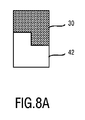
更に、リブ42,42’及び凹部44,44’は、本発明の範囲から逸脱せずに様々な異なる断面を有し得ることが留意されるべきである。リブ42,42’及び凹部44,44’は、必ずしも長方形の断面を有さなければならないわけではない。図8A−8Dに示すように、リブ42,42’は、技術的な原理を維持しながら、例えば、(図8Aに示すような)階段形状の断面、(図8Bに示すような)丸い断面、(図8Cに示すような)三角形の断面、又は(図8Dに示すような)方形の断面有してもよい。コーム歯30の断面は(相対物としての)リブ42,42’及び/又は凹部44,44’の断面に適合させられるのが好ましいことも図8から明らかになる。簡潔性の理由のために、図8はリブ42,42’の4つの着想可能な断面のみを示している。しかしながら、当業者は凹部44,44’が類似の断面を有してよいことに気付くであろう。既に前に指摘したように、凹部44,44’は、波形表面40,40におけるリブ42,42’の間の空間に他ならない。これは、リブ42,42’の断面が変更されるや否や、凹部44,44’の断面が相応して変更されることを意味する。一層更に、図8A−8Dに示す例示的な異なる断面は両方の実施態様(図2及び3に示す第1の実施態様並びに図5及び6に示す第2の実施態様)において実施されてよいことが留意されるべきである。当業者は上述の発明的な原理を維持することによって複数の更なる断面が可能であることにも気付くであろう。
Furthermore, it should be noted that the
図9及び10は、コームアタッチメント20の2つの異なる実施態様を示している。そこでは、ヘアクリッパ10とコーム20とを含むヘアクリッピング装置100が、底から、即ち、ハウジング12の遠位端16を見て示されている。
9 and 10 show two different embodiments of the
図9に示す第1の実施態様によれば、コームアタッチメント20は(底コーム歯62としても示す)複数の底リブ62を含み、底リブ62はコーム歯30と平行に走り、コーム20がヘアクリッパ10に取り付けられるときにハウジング12の遠位端16を覆う。これらの底リブ62は、コーム20を使用者の頭に配置するために用いられてよい一種の格子(grating)である。よって、これらの底リブ62は使用者の頭皮の上を滑動してよい。これはコーム20を正しく方向付けるのを容易にし、毛切断のためにさえも役立つ。図9に示すように、コーム20の底リブ62は、切断アセンブリ14の下に間隙が生じるように、コーム歯30に直接的に接続されていない。これはより一層短い毛切断長さを可能にする。しかしながら、コーム歯30と底リブ62との間の間隙は必須でないことが留意されるべきである。各コーム歯30は、それぞれの底リブ62に直接的に接続されてもよい。これはより長い毛切断長さにとって特に有利である。なぜならば、そのような不断のコームアタッチメント20は、機械的安定性の増大を有するからである。
According to the first embodiment shown in FIG. 9, the
図10に示す第2の実施態様は、目詰まり防止に関して改良されている。この実施態様によれば、コームアタッチメント20は、僅かに湾曲してコームアタッチメント20の背面側34から突出してよい2つのアーム64,64’を含む。1つのアーム64,64’が、コームアタッチメント20の各側方側に配置される(左側に1つ及び右側に1つ)。底リブ62と同様に、コーム20がヘアクリッパ10に取り付けられるときに、これらのアーム64,64’はハウジング12の遠位端16と重なり合う。(参照番号66によって示す)2つのアーム64,64’の間の空間は、開放されたままにされた第1の実施態様と対照的である。コームのこの開放下面は、切断された毛のための自由な毛の流れをもたらすので、切断された毛はアーム64,64’の間の開放孔66を通じて直ぐに落ちる。切断されなかった毛もコーム20からの自由な毛の流れを有する。特により長い毛を用いるときに、これは、効率に否定的な影響を及ぼし得る切断されなかった毛を巧みに処理することなく、自由な毛の流れを創り出している。従って、図10に示す第2の実施態様に従ったコーム20は、本発明が目的とする目詰まり防止を更に向上させる。
The second embodiment shown in FIG. 10 is improved with respect to prevention of clogging. According to this embodiment, the
本発明を図面中に詳細に例示し且つ前述の記述中に詳細に記載したが、そのような例示及び記述は例示的又は例証的であると考えられるべきであり、限定的であると考えられるべきではない。即ち、本発明は開示の実施態様に限定されない。請求する発明を実施する当業者は、図面、本開示、及び付属の請求項の研究から、開示の実施態様に対する他の変形を理解し且つ実現し得る。 While the invention has been illustrated in detail in the drawings and described in detail in the foregoing description, such illustration and description are to be considered illustrative or exemplary and limited Should not. The invention is not limited to the disclosed embodiments. Those skilled in the art of practicing the claimed invention may understand and realize other variations to the disclosed embodiments from a study of the drawings, this disclosure, and the appended claims.
請求項において、「含む」という用語は他の要素又はステップを排除せず、単数形の表現は複数を排除しない。単一の要素又は他のユニットが請求項中に引用される幾つかの品目の機能を充足してよい。特定の手段が相互に異なる従属項において引用されているという単なる事実は、これらの手段の組み合わせを有利に用い得ないことを示さない。 In the claims, the term “comprising” does not exclude other elements or steps, and the singular expression does not exclude the plurality. A single element or other unit may fulfill the functions of several items recited in the claims. The mere fact that certain measures are recited in mutually different dependent claims does not indicate that a combination of these measured cannot be used to advantage.
請求項中の如何なる参照符号も、その範囲を限定するものとして解釈されてはならない。 Any reference signs in the claims should not be construed as limiting the scope.
Claims (10)
該ハウジングの遠位端に配置され且つ静止切断ブレードと可動切断ブレードとを含む切断アセンブリと、
前記ハウジングに解放可能に取り付け可能であり且つ複数のコーム歯を含むコームアタッチメントとを含み、
前記ハウジングの正面側が、前記遠位端及び前記切断アセンブリに対して横断方向に走り、互いに平行に走る複数の隣接するリブ及び凹部を備える波形表面を含み、
前記コーム歯の正面側が、前記ハウジングから離れる方向に面し、前記コーム歯の反対側の背面側が、前記コームアタッチメントが前記ハウジングに取り付けられるときに前記波形表面と接触し、
各コーム歯の前記背面側が前記凹部のうちのそれぞれの凹部のベースと接触するように、前記コームアタッチメントの前記コーム歯は、前記コームアタッチメントが前記ハウジングに取り付けられるときに、前記凹部内に少なくとも部分的に受け入れられ、
前記コームアタッチメントの前記コーム歯は、前記凹部の幅と実質的に等しい幅を有することを特徴とする、
ヘアクリッピング装置。 A housing;
A cutting assembly disposed at a distal end of the housing and including a stationary cutting blade and a movable cutting blade;
A comb attachment releasably attachable to the housing and including a plurality of comb teeth;
The front side of the housing includes a corrugated surface comprising a plurality of adjacent ribs and recesses running transverse to the distal end and the cutting assembly and running parallel to each other;
The front side of the comb teeth faces away from the housing, and the back side opposite the comb teeth contacts the corrugated surface when the comb attachment is attached to the housing ;
The comb teeth of the comb attachment are at least partially in the recess when the comb attachment is attached to the housing such that the back side of each comb tooth contacts the base of the respective recess of the recesses. Accepted,
The comb teeth of the comb attachment have a width substantially equal to the width of the recess ,
Hair clipping device.
該ハウジングの遠位端に配置され且つ静止切断ブレードと可動切断ブレードとを含む切断アセンブリと、A cutting assembly disposed at a distal end of the housing and including a stationary cutting blade and a movable cutting blade;
前記ハウジングに解放可能に取り付け可能であり且つ複数のコーム歯を含むコームアタッチメントとを含み、A comb attachment releasably attachable to the housing and including a plurality of comb teeth;
前記ハウジングの正面側が、前記遠位端及び前記切断アセンブリに対して横断方向に走り、互いに平行に走る複数の隣接するリブ及び凹部を備える波形表面を含み、The front side of the housing includes a corrugated surface comprising a plurality of adjacent ribs and recesses running transverse to the distal end and the cutting assembly and running parallel to each other;
前記コーム歯の正面側が、前記ハウジングから離れる方向に面し、前記コーム歯の反対側の背面側が、前記コームアタッチメントが前記ハウジングに取り付けられるときに前記波形表面と接触し、The front side of the comb teeth faces away from the housing, and the back side opposite the comb teeth contacts the corrugated surface when the comb attachment is attached to the housing;
各コーム歯の前記背面側は、前記コームアタッチメントが前記ハウジングに取り付けられるときに、前記リブのうちのそれぞれのリブの上方側と接触し、The back side of each comb tooth contacts the upper side of each of the ribs when the comb attachment is attached to the housing;
前記コームアタッチメントの前記コーム歯は、前記リブの幅と実質的に等しい或いは前記リブの幅を超える幅を有することを特徴とする、The comb teeth of the comb attachment have a width substantially equal to or greater than a width of the rib,
ヘアクリッピング装置。Hair clipping device.
Applications Claiming Priority (3)
| Application Number | Priority Date | Filing Date | Title |
|---|---|---|---|
| EP13182199.3 | 2013-08-29 | ||
| EP13182199 | 2013-08-29 | ||
| PCT/EP2014/067548 WO2015028330A1 (en) | 2013-08-29 | 2014-08-18 | Hair clipping device |
Publications (3)
| Publication Number | Publication Date |
|---|---|
| JP2016529009A JP2016529009A (en) | 2016-09-23 |
| JP2016529009A5 JP2016529009A5 (en) | 2018-05-31 |
| JP6397917B2 true JP6397917B2 (en) | 2018-09-26 |
Family
ID=49054424
Family Applications (1)
| Application Number | Title | Priority Date | Filing Date |
|---|---|---|---|
| JP2016537219A Active JP6397917B2 (en) | 2013-08-29 | 2014-08-18 | Hair clipping device |
Country Status (9)
| Country | Link |
|---|---|
| US (1) | US10105856B2 (en) |
| EP (1) | EP3038800B1 (en) |
| JP (1) | JP6397917B2 (en) |
| CN (2) | CN104416597B (en) |
| BR (1) | BR112016003981B1 (en) |
| ES (1) | ES2701524T3 (en) |
| RU (1) | RU2693584C2 (en) |
| TR (1) | TR201819053T4 (en) |
| WO (1) | WO2015028330A1 (en) |
Families Citing this family (16)
| Publication number | Priority date | Publication date | Assignee | Title |
|---|---|---|---|---|
| JP6397917B2 (en) * | 2013-08-29 | 2018-09-26 | コーニンクレッカ フィリップス エヌ ヴェKoninklijke Philips N.V. | Hair clipping device |
| US10828793B2 (en) * | 2015-04-15 | 2020-11-10 | Rk Inventions, Llc | Razor assembly |
| JP6720289B2 (en) | 2015-08-04 | 2020-07-08 | コーニンクレッカ フィリップス エヌ ヴェKoninklijke Philips N.V. | Hair containers and kits for hair cutting equipment |
| USD785249S1 (en) * | 2015-09-09 | 2017-04-25 | Chuka Torres | Blade setter for electric clippers |
| USD813459S1 (en) * | 2015-10-07 | 2018-03-20 | Thomas James Sinnott | Hair clipper guide attachment |
| EP3300858B1 (en) * | 2016-09-28 | 2021-04-07 | Braun GmbH | Beard trimmer |
| EP3300856B1 (en) | 2016-09-28 | 2021-06-02 | Braun GmbH | Beard trimmer |
| EP3300857A1 (en) * | 2016-09-28 | 2018-04-04 | Braun GmbH | Beard trimmer |
| RU2021133268A (en) * | 2017-02-27 | 2021-12-16 | Спектрум Брэндз, Инк. | ELECTRIC HAIR TRIMMER WITH KNIFE LIMITER |
| EP3388206A1 (en) * | 2017-04-14 | 2018-10-17 | Koninklijke Philips N.V. | Attachment comb, cutting head and hair cutting appliance |
| EP3403779A1 (en) * | 2017-05-15 | 2018-11-21 | Koninklijke Philips N.V. | Spacing comb and hair cutting appliance |
| EP3466620A1 (en) * | 2017-10-04 | 2019-04-10 | Koninklijke Philips N.V. | Comb for a hair clipper |
| EP3527339A1 (en) * | 2018-02-20 | 2019-08-21 | Koninklijke Philips N.V. | A comb for a hair cutting appliance |
| EP3677393A1 (en) * | 2019-01-04 | 2020-07-08 | Koninklijke Philips N.V. | Combs for hair cutting appliances |
| CN110089450A (en) * | 2019-06-17 | 2019-08-06 | 宁波宏都模塑有限公司 | Multipurpose Pet comb |
| ES2930094T3 (en) * | 2020-04-24 | 2022-12-07 | Wahl Gmbh | Wavy edge cutting set |
Family Cites Families (28)
| Publication number | Priority date | Publication date | Assignee | Title |
|---|---|---|---|---|
| US1214430A (en) * | 1916-06-29 | 1917-01-30 | Russell D Cook | Attachment for shearing-machines. |
| US1503986A (en) * | 1923-10-30 | 1924-08-05 | Dean John | Hair clipper |
| US2941293A (en) * | 1958-12-17 | 1960-06-21 | Chester J Mazzoni | Hair clipper |
| US3287805A (en) | 1966-04-19 | 1966-11-29 | Charme Paul E Du | Hair clipper with cut regulator indicator |
| US4085503A (en) | 1974-12-23 | 1978-04-25 | Sunbeam Corporation | Electric dry shaver with adjustable long hair trimmer |
| US4138809A (en) * | 1977-08-17 | 1979-02-13 | Sperry Rand Corporation | Hair trimmer |
| JPS60108074A (en) * | 1983-11-17 | 1985-06-13 | 松下電工株式会社 | Attachment of hair cutter |
| JPS6179484A (en) * | 1984-09-25 | 1986-04-23 | 松下電工株式会社 | Hair cutter |
| US5050305A (en) * | 1985-09-13 | 1991-09-24 | Remington Products, Inc. | Hair trimmer with comb attachment |
| JP3017508B2 (en) * | 1989-12-25 | 2000-03-13 | 松下電工株式会社 | Hair cutter |
| US5084973A (en) * | 1990-02-14 | 1992-02-04 | Geer Frederick J | Adjustable spacer for hair clippers |
| DE4013436A1 (en) * | 1990-04-27 | 1991-10-31 | Braun Ag | ELECTRIC HAIRCUTTER |
| JP2986925B2 (en) | 1990-05-28 | 1999-12-06 | 松下電工株式会社 | Hair cutter |
| US5084974A (en) * | 1991-01-22 | 1992-02-04 | Andis Company | Clipper with lever actuated adjustable comb |
| JPH05228270A (en) * | 1992-02-25 | 1993-09-07 | Matsushita Electric Works Ltd | Hair cutter |
| US6079103A (en) * | 1998-01-09 | 2000-06-27 | Wahl Clipper Corporation | Adjustable attachment comb |
| EP1156909A1 (en) * | 1999-12-22 | 2001-11-28 | Koninklijke Philips Electronics N.V. | Hair-cutting system including a hair-cutting apparatus and a comb device |
| TW485885U (en) * | 2001-05-04 | 2002-05-01 | Yun-Sheng Lin | Hair height setting device for clippers |
| JP4466077B2 (en) | 2003-12-26 | 2010-05-26 | パナソニック電工株式会社 | Hair cutter |
| DE102004021503B3 (en) | 2004-04-30 | 2006-02-09 | Braun Gmbh | Dry shaver and hair cutter has venetian blind type attachment with adjustable separation between attachment and housing |
| CN1968793A (en) | 2004-06-15 | 2007-05-23 | 皇家飞利浦电子股份有限公司 | Clipping device and comb unit |
| CN101443164A (en) | 2006-05-11 | 2009-05-27 | 皇家飞利浦电子股份有限公司 | Comb device and hair-cutting system |
| CN201124487Y (en) * | 2007-10-31 | 2008-10-01 | 张金河 | Multifunctional limiting comb for hair clipper |
| EP2108489A1 (en) * | 2008-04-08 | 2009-10-14 | Faco S.A. | Hair clippers with cutting guide |
| JP5821005B2 (en) | 2010-12-17 | 2015-11-24 | パナソニックIpマネジメント株式会社 | Hair cutter |
| CN202129815U (en) * | 2011-06-17 | 2012-02-01 | 惠阳亚伦塑胶电器实业有限公司 | Angle-adjustable accessory comb of hair clipper |
| CN103231395B (en) | 2013-04-01 | 2015-09-23 | 宁波邦首电器有限公司 | The electric hair cutter of knob regulation comb row and moving knife |
| JP6397917B2 (en) * | 2013-08-29 | 2018-09-26 | コーニンクレッカ フィリップス エヌ ヴェKoninklijke Philips N.V. | Hair clipping device |
-
2014
- 2014-08-18 JP JP2016537219A patent/JP6397917B2/en active Active
- 2014-08-18 EP EP14752342.7A patent/EP3038800B1/en active Active
- 2014-08-18 ES ES14752342T patent/ES2701524T3/en active Active
- 2014-08-18 WO PCT/EP2014/067548 patent/WO2015028330A1/en active Application Filing
- 2014-08-18 RU RU2016111286A patent/RU2693584C2/en active
- 2014-08-18 US US14/913,477 patent/US10105856B2/en active Active
- 2014-08-18 TR TR2018/19053T patent/TR201819053T4/en unknown
- 2014-08-18 BR BR112016003981-5A patent/BR112016003981B1/en not_active IP Right Cessation
- 2014-08-28 CN CN201410441232.0A patent/CN104416597B/en active Active
- 2014-08-28 CN CN201420500386.8U patent/CN204339814U/en active Active
Also Published As
| Publication number | Publication date |
|---|---|
| CN104416597A (en) | 2015-03-18 |
| CN104416597B (en) | 2018-03-27 |
| RU2693584C2 (en) | 2019-07-03 |
| EP3038800A1 (en) | 2016-07-06 |
| EP3038800B1 (en) | 2018-10-10 |
| JP2016529009A (en) | 2016-09-23 |
| RU2016111286A3 (en) | 2018-06-27 |
| BR112016003981A2 (en) | 2017-08-01 |
| BR112016003981B1 (en) | 2021-09-14 |
| TR201819053T4 (en) | 2019-01-21 |
| US20160207208A1 (en) | 2016-07-21 |
| US10105856B2 (en) | 2018-10-23 |
| CN204339814U (en) | 2015-05-20 |
| ES2701524T3 (en) | 2019-02-22 |
| RU2016111286A (en) | 2017-10-04 |
| WO2015028330A1 (en) | 2015-03-05 |
Similar Documents
| Publication | Publication Date | Title |
|---|---|---|
| JP6397917B2 (en) | Hair clipping device | |
| EP3126105B1 (en) | Hair clipping device. | |
| CN107107351B (en) | Dry shaver | |
| JP6222787B2 (en) | Blade set, hair cutting device, and related manufacturing method | |
| JP7194697B2 (en) | Spacing combs and hair cutting tools | |
| JP6919068B2 (en) | Hair clipper device | |
| US8555509B2 (en) | Shaving unit for an electric shaver | |
| BR112016023796B1 (en) | stationary blade, blade set, and method of making a metal-plastic composite stationary blade | |
| JP6798889B2 (en) | Hair clipping device | |
| CN113618788A (en) | Electric beard trimmer | |
| JP6970830B2 (en) | Cutting unit | |
| JP6848128B2 (en) | Comb for hair clippers | |
| JP7071539B2 (en) | Blade set and hair cutting equipment | |
| WO2008023529A1 (en) | Hair cutter | |
| JP2021507789A (en) | Comb for hair cutting device | |
| KR20200019121A (en) | Shaver cartridges | |
| KR200482245Y1 (en) | Hair Clipper with Cut Comb for Easy Hair Cutting | |
| MX2008001670A (en) | Electric razors. |
Legal Events
| Date | Code | Title | Description |
|---|---|---|---|
| A621 | Written request for application examination |
Free format text: JAPANESE INTERMEDIATE CODE: A621 Effective date: 20170816 |
|
| A521 | Request for written amendment filed |
Free format text: JAPANESE INTERMEDIATE CODE: A523 Effective date: 20180410 |
|
| A871 | Explanation of circumstances concerning accelerated examination |
Free format text: JAPANESE INTERMEDIATE CODE: A871 Effective date: 20180410 |
|
| A975 | Report on accelerated examination |
Free format text: JAPANESE INTERMEDIATE CODE: A971005 Effective date: 20180425 |
|
| A131 | Notification of reasons for refusal |
Free format text: JAPANESE INTERMEDIATE CODE: A131 Effective date: 20180508 |
|
| TRDD | Decision of grant or rejection written | ||
| A01 | Written decision to grant a patent or to grant a registration (utility model) |
Free format text: JAPANESE INTERMEDIATE CODE: A01 Effective date: 20180807 |
|
| A61 | First payment of annual fees (during grant procedure) |
Free format text: JAPANESE INTERMEDIATE CODE: A61 Effective date: 20180903 |
|
| R150 | Certificate of patent or registration of utility model |
Ref document number: 6397917 Country of ref document: JP Free format text: JAPANESE INTERMEDIATE CODE: R150 |
|
| R250 | Receipt of annual fees |
Free format text: JAPANESE INTERMEDIATE CODE: R250 |
|
| R250 | Receipt of annual fees |
Free format text: JAPANESE INTERMEDIATE CODE: R250 |
|
| R250 | Receipt of annual fees |
Free format text: JAPANESE INTERMEDIATE CODE: R250 |