JP6396892B2 - Pressure control for breathing comfort - Google Patents
Pressure control for breathing comfort Download PDFInfo
- Publication number
- JP6396892B2 JP6396892B2 JP2015512716A JP2015512716A JP6396892B2 JP 6396892 B2 JP6396892 B2 JP 6396892B2 JP 2015512716 A JP2015512716 A JP 2015512716A JP 2015512716 A JP2015512716 A JP 2015512716A JP 6396892 B2 JP6396892 B2 JP 6396892B2
- Authority
- JP
- Japan
- Prior art keywords
- current signal
- derived
- signal
- current
- inspiration
- Prior art date
- Legal status (The legal status is an assumption and is not a legal conclusion. Google has not performed a legal analysis and makes no representation as to the accuracy of the status listed.)
- Active
Links
Images


Classifications
-
- A—HUMAN NECESSITIES
- A61—MEDICAL OR VETERINARY SCIENCE; HYGIENE
- A61B—DIAGNOSIS; SURGERY; IDENTIFICATION
- A61B5/00—Measuring for diagnostic purposes; Identification of persons
- A61B5/08—Detecting, measuring or recording devices for evaluating the respiratory organs
- A61B5/087—Measuring breath flow
-
- A—HUMAN NECESSITIES
- A61—MEDICAL OR VETERINARY SCIENCE; HYGIENE
- A61B—DIAGNOSIS; SURGERY; IDENTIFICATION
- A61B5/00—Measuring for diagnostic purposes; Identification of persons
- A61B5/08—Detecting, measuring or recording devices for evaluating the respiratory organs
- A61B5/097—Devices for facilitating collection of breath or for directing breath into or through measuring devices
-
- A—HUMAN NECESSITIES
- A61—MEDICAL OR VETERINARY SCIENCE; HYGIENE
- A61M—DEVICES FOR INTRODUCING MEDIA INTO, OR ONTO, THE BODY; DEVICES FOR TRANSDUCING BODY MEDIA OR FOR TAKING MEDIA FROM THE BODY; DEVICES FOR PRODUCING OR ENDING SLEEP OR STUPOR
- A61M16/00—Devices for influencing the respiratory system of patients by gas treatment, e.g. mouth-to-mouth respiration; Tracheal tubes
- A61M16/0003—Accessories therefor, e.g. sensors, vibrators, negative pressure
-
- A—HUMAN NECESSITIES
- A61—MEDICAL OR VETERINARY SCIENCE; HYGIENE
- A61M—DEVICES FOR INTRODUCING MEDIA INTO, OR ONTO, THE BODY; DEVICES FOR TRANSDUCING BODY MEDIA OR FOR TAKING MEDIA FROM THE BODY; DEVICES FOR PRODUCING OR ENDING SLEEP OR STUPOR
- A61M16/00—Devices for influencing the respiratory system of patients by gas treatment, e.g. mouth-to-mouth respiration; Tracheal tubes
- A61M16/0057—Pumps therefor
- A61M16/0066—Blowers or centrifugal pumps
- A61M16/0069—Blowers or centrifugal pumps the speed thereof being controlled by respiratory parameters, e.g. by inhalation
-
- A—HUMAN NECESSITIES
- A61—MEDICAL OR VETERINARY SCIENCE; HYGIENE
- A61M—DEVICES FOR INTRODUCING MEDIA INTO, OR ONTO, THE BODY; DEVICES FOR TRANSDUCING BODY MEDIA OR FOR TAKING MEDIA FROM THE BODY; DEVICES FOR PRODUCING OR ENDING SLEEP OR STUPOR
- A61M16/00—Devices for influencing the respiratory system of patients by gas treatment, e.g. mouth-to-mouth respiration; Tracheal tubes
- A61M16/021—Devices for influencing the respiratory system of patients by gas treatment, e.g. mouth-to-mouth respiration; Tracheal tubes operated by electrical means
- A61M16/022—Control means therefor
- A61M16/024—Control means therefor including calculation means, e.g. using a processor
-
- A—HUMAN NECESSITIES
- A61—MEDICAL OR VETERINARY SCIENCE; HYGIENE
- A61M—DEVICES FOR INTRODUCING MEDIA INTO, OR ONTO, THE BODY; DEVICES FOR TRANSDUCING BODY MEDIA OR FOR TAKING MEDIA FROM THE BODY; DEVICES FOR PRODUCING OR ENDING SLEEP OR STUPOR
- A61M16/00—Devices for influencing the respiratory system of patients by gas treatment, e.g. mouth-to-mouth respiration; Tracheal tubes
- A61M16/06—Respiratory or anaesthetic masks
-
- A—HUMAN NECESSITIES
- A61—MEDICAL OR VETERINARY SCIENCE; HYGIENE
- A61M—DEVICES FOR INTRODUCING MEDIA INTO, OR ONTO, THE BODY; DEVICES FOR TRANSDUCING BODY MEDIA OR FOR TAKING MEDIA FROM THE BODY; DEVICES FOR PRODUCING OR ENDING SLEEP OR STUPOR
- A61M16/00—Devices for influencing the respiratory system of patients by gas treatment, e.g. mouth-to-mouth respiration; Tracheal tubes
- A61M16/20—Valves specially adapted to medical respiratory devices
-
- A—HUMAN NECESSITIES
- A61—MEDICAL OR VETERINARY SCIENCE; HYGIENE
- A61M—DEVICES FOR INTRODUCING MEDIA INTO, OR ONTO, THE BODY; DEVICES FOR TRANSDUCING BODY MEDIA OR FOR TAKING MEDIA FROM THE BODY; DEVICES FOR PRODUCING OR ENDING SLEEP OR STUPOR
- A61M16/00—Devices for influencing the respiratory system of patients by gas treatment, e.g. mouth-to-mouth respiration; Tracheal tubes
- A61M16/06—Respiratory or anaesthetic masks
- A61M16/0683—Holding devices therefor
-
- A—HUMAN NECESSITIES
- A61—MEDICAL OR VETERINARY SCIENCE; HYGIENE
- A61M—DEVICES FOR INTRODUCING MEDIA INTO, OR ONTO, THE BODY; DEVICES FOR TRANSDUCING BODY MEDIA OR FOR TAKING MEDIA FROM THE BODY; DEVICES FOR PRODUCING OR ENDING SLEEP OR STUPOR
- A61M16/00—Devices for influencing the respiratory system of patients by gas treatment, e.g. mouth-to-mouth respiration; Tracheal tubes
- A61M16/10—Preparation of respiratory gases or vapours
- A61M16/105—Filters
- A61M16/1055—Filters bacterial
-
- A—HUMAN NECESSITIES
- A61—MEDICAL OR VETERINARY SCIENCE; HYGIENE
- A61M—DEVICES FOR INTRODUCING MEDIA INTO, OR ONTO, THE BODY; DEVICES FOR TRANSDUCING BODY MEDIA OR FOR TAKING MEDIA FROM THE BODY; DEVICES FOR PRODUCING OR ENDING SLEEP OR STUPOR
- A61M16/00—Devices for influencing the respiratory system of patients by gas treatment, e.g. mouth-to-mouth respiration; Tracheal tubes
- A61M16/10—Preparation of respiratory gases or vapours
- A61M16/105—Filters
- A61M16/106—Filters in a path
- A61M16/107—Filters in a path in the inspiratory path
-
- A—HUMAN NECESSITIES
- A61—MEDICAL OR VETERINARY SCIENCE; HYGIENE
- A61M—DEVICES FOR INTRODUCING MEDIA INTO, OR ONTO, THE BODY; DEVICES FOR TRANSDUCING BODY MEDIA OR FOR TAKING MEDIA FROM THE BODY; DEVICES FOR PRODUCING OR ENDING SLEEP OR STUPOR
- A61M16/00—Devices for influencing the respiratory system of patients by gas treatment, e.g. mouth-to-mouth respiration; Tracheal tubes
- A61M16/0003—Accessories therefor, e.g. sensors, vibrators, negative pressure
- A61M2016/0015—Accessories therefor, e.g. sensors, vibrators, negative pressure inhalation detectors
- A61M2016/0018—Accessories therefor, e.g. sensors, vibrators, negative pressure inhalation detectors electrical
- A61M2016/0021—Accessories therefor, e.g. sensors, vibrators, negative pressure inhalation detectors electrical with a proportional output signal, e.g. from a thermistor
-
- A—HUMAN NECESSITIES
- A61—MEDICAL OR VETERINARY SCIENCE; HYGIENE
- A61M—DEVICES FOR INTRODUCING MEDIA INTO, OR ONTO, THE BODY; DEVICES FOR TRANSDUCING BODY MEDIA OR FOR TAKING MEDIA FROM THE BODY; DEVICES FOR PRODUCING OR ENDING SLEEP OR STUPOR
- A61M16/00—Devices for influencing the respiratory system of patients by gas treatment, e.g. mouth-to-mouth respiration; Tracheal tubes
- A61M16/0003—Accessories therefor, e.g. sensors, vibrators, negative pressure
- A61M2016/0027—Accessories therefor, e.g. sensors, vibrators, negative pressure pressure meter
-
- A—HUMAN NECESSITIES
- A61—MEDICAL OR VETERINARY SCIENCE; HYGIENE
- A61M—DEVICES FOR INTRODUCING MEDIA INTO, OR ONTO, THE BODY; DEVICES FOR TRANSDUCING BODY MEDIA OR FOR TAKING MEDIA FROM THE BODY; DEVICES FOR PRODUCING OR ENDING SLEEP OR STUPOR
- A61M16/00—Devices for influencing the respiratory system of patients by gas treatment, e.g. mouth-to-mouth respiration; Tracheal tubes
- A61M16/0003—Accessories therefor, e.g. sensors, vibrators, negative pressure
- A61M2016/003—Accessories therefor, e.g. sensors, vibrators, negative pressure with a flowmeter
-
- A—HUMAN NECESSITIES
- A61—MEDICAL OR VETERINARY SCIENCE; HYGIENE
- A61M—DEVICES FOR INTRODUCING MEDIA INTO, OR ONTO, THE BODY; DEVICES FOR TRANSDUCING BODY MEDIA OR FOR TAKING MEDIA FROM THE BODY; DEVICES FOR PRODUCING OR ENDING SLEEP OR STUPOR
- A61M2205/00—General characteristics of the apparatus
- A61M2205/33—Controlling, regulating or measuring
- A61M2205/3317—Electromagnetic, inductive or dielectric measuring means
-
- A—HUMAN NECESSITIES
- A61—MEDICAL OR VETERINARY SCIENCE; HYGIENE
- A61M—DEVICES FOR INTRODUCING MEDIA INTO, OR ONTO, THE BODY; DEVICES FOR TRANSDUCING BODY MEDIA OR FOR TAKING MEDIA FROM THE BODY; DEVICES FOR PRODUCING OR ENDING SLEEP OR STUPOR
- A61M2205/00—General characteristics of the apparatus
- A61M2205/33—Controlling, regulating or measuring
- A61M2205/3327—Measuring
-
- A—HUMAN NECESSITIES
- A61—MEDICAL OR VETERINARY SCIENCE; HYGIENE
- A61M—DEVICES FOR INTRODUCING MEDIA INTO, OR ONTO, THE BODY; DEVICES FOR TRANSDUCING BODY MEDIA OR FOR TAKING MEDIA FROM THE BODY; DEVICES FOR PRODUCING OR ENDING SLEEP OR STUPOR
- A61M2205/00—General characteristics of the apparatus
- A61M2205/33—Controlling, regulating or measuring
- A61M2205/3331—Pressure; Flow
- A61M2205/3334—Measuring or controlling the flow rate
-
- A—HUMAN NECESSITIES
- A61—MEDICAL OR VETERINARY SCIENCE; HYGIENE
- A61M—DEVICES FOR INTRODUCING MEDIA INTO, OR ONTO, THE BODY; DEVICES FOR TRANSDUCING BODY MEDIA OR FOR TAKING MEDIA FROM THE BODY; DEVICES FOR PRODUCING OR ENDING SLEEP OR STUPOR
- A61M2205/00—General characteristics of the apparatus
- A61M2205/50—General characteristics of the apparatus with microprocessors or computers
- A61M2205/502—User interfaces, e.g. screens or keyboards
- A61M2205/505—Touch-screens; Virtual keyboard or keypads; Virtual buttons; Soft keys; Mouse touches
-
- A—HUMAN NECESSITIES
- A61—MEDICAL OR VETERINARY SCIENCE; HYGIENE
- A61M—DEVICES FOR INTRODUCING MEDIA INTO, OR ONTO, THE BODY; DEVICES FOR TRANSDUCING BODY MEDIA OR FOR TAKING MEDIA FROM THE BODY; DEVICES FOR PRODUCING OR ENDING SLEEP OR STUPOR
- A61M2205/00—General characteristics of the apparatus
- A61M2205/50—General characteristics of the apparatus with microprocessors or computers
- A61M2205/52—General characteristics of the apparatus with microprocessors or computers with memories providing a history of measured variating parameters of apparatus or patient
-
- A—HUMAN NECESSITIES
- A61—MEDICAL OR VETERINARY SCIENCE; HYGIENE
- A61M—DEVICES FOR INTRODUCING MEDIA INTO, OR ONTO, THE BODY; DEVICES FOR TRANSDUCING BODY MEDIA OR FOR TAKING MEDIA FROM THE BODY; DEVICES FOR PRODUCING OR ENDING SLEEP OR STUPOR
- A61M2230/00—Measuring parameters of the user
- A61M2230/40—Respiratory characteristics
Description
本技術は、換気、気道陽圧(CPAP:Positive Airway Pressure)処置又は非侵襲的陽圧換気(NIPPV:Non-Invasive Positive Pressure Ventilation)を含む補助呼吸中に呼吸流量の指示子を検出する方法及び装置に関する。より詳細には、本技術は、呼吸についての改善された快適さを提供するため、補助呼吸中に患者に供給される圧力処置を制御することに関する。本方法及び装置は、睡眠呼吸障害(SDB:Sleep Disordered Breathing)、いびき障害(snoring disorder)、又は他の呼吸障害を処置するために使用することができる。 The present technology includes a method for detecting an indicator of respiratory flow during assisted breathing, including ventilation, positive airway pressure (CPAP) treatment, or non-invasive positive pressure ventilation (NIPPV) and Relates to the device. More particularly, the present technology relates to controlling the pressure treatment delivered to a patient during assisted breathing to provide improved comfort for breathing. The method and apparatus can be used to treat sleep disordered breathing (SDB), snoring disorder, or other respiratory disorders.
[関連出願の相互参照]
本出願は、2012年5月14日に出願された「Control of Pressure For Breathing Comfort」と題する米国仮特許出願第61/646,571号の出願日の利益を主張する。この特許文献の開示は引用することによりその全体が本明細書の一部をなすものとする。
[Cross-reference of related applications]
This application claims the benefit of the filing date of US Provisional Patent Application No. 61 / 646,571, filed May 14, 2012, entitled “Control of Pressure For Breathing Comfort”. The disclosure of this patent document is incorporated herein by reference in its entirety.
SDBのCPAP処置は、導管及びマスクを使用して、患者の気道に、加圧された呼吸に適したガス、通常、空気を送出することを含むことができる。CPAPについて使用されるガス圧力は、通常、患者要件に応じて、最大180L/分の流量(マスクにおいて測定)で、4cmH2O〜28cmH2Oの範囲になる。加圧されたガスは、患者の気道について空気スプリント(pneumatic splint)として作用すると言われ、特に呼吸の吸気フェーズ中の気道圧潰を防止する。複相型(bi-level)PAPデバイスでは、患者についての改善された呼吸の快適さを提供するために、より高い圧力が呼吸サイクルの吸気フェーズ中に提供され、より低い圧力が呼吸サイクルの呼気フェーズ中に提供される。幾つかのCPAPデバイスでは、吸気圧力処置設定からの略1cmH2O〜3cmH2Oの圧力の低下であると考えることができる呼気圧力軽減が、吸気フェーズと比較して呼気フェーズ中に提供される。 SDB CPAP treatment may involve delivering a pressurized breathable gas, usually air, into the patient's airway using a conduit and mask. The gas pressure used for CPAP typically ranges from 4 cmH 2 O to 28 cmH 2 O at a flow rate (measured at the mask) of up to 180 L / min, depending on patient requirements. The pressurized gas is said to act as a pneumatic splint for the patient's airway, preventing airway collapse, particularly during the inspiratory phase of breathing. In bi-level PAP devices, higher pressure is provided during the inspiratory phase of the respiratory cycle and lower pressure is exhaled in the respiratory cycle to provide improved breathing comfort for the patient. Provided during the phase. In some CPAP devices, expiratory pressure relief is provided during the expiratory phase compared to the inspiratory phase, which can be thought of as a pressure drop of approximately 1 cmH 2 O to 3 cmH 2 O from the inspiratory pressure treatment setting. .
CPAP装置は、通常、鼻マスク若しくは口腔鼻マスク、又は鼻クッション若しくは鼻ピローの装置等の患者インタフェースにつながる空気送出チューブを介して患者に、空気等の加圧された呼吸ガスを供給するための流れ生成器又はブロワを含む。 CPAP devices are typically for delivering pressurized breathing gas, such as air, to a patient via an air delivery tube that leads to a patient interface, such as a nasal or oral nasal mask, or nasal cushion or nasal pillow device. Includes a flow generator or blower.
本技術の一形態は、モータ電流測定に基づいて気道陽圧(PAP)デバイスによってユーザに供給される圧力を制御するようになっている改良された方法及び装置を含む。こうした装置は、空気流を測定するために流量センサ又は圧力センサを含むことなく実装することができる。 One form of the present technology includes an improved method and apparatus adapted to control the pressure supplied to a user by a positive airway pressure (PAP) device based on motor current measurements. Such a device can be implemented without including a flow sensor or pressure sensor to measure airflow.
本技術の別の形態は、気道陽圧(PAP)デバイス内のブロワに供給される電流の測定量に基づいて呼吸流量の変化を確定するようになっている方法及び装置を含む。呼吸流量の検出される変化は、ブロワの速度を制御し、その結果、ブロワにより供給される圧力を制御するために使用することができる。 Another form of the present technology includes a method and apparatus adapted to determine a change in respiratory flow based on a measured amount of current supplied to a blower in a positive airway pressure (PAP) device. The detected change in respiratory flow can be used to control the speed of the blower and consequently the pressure supplied by the blower.
本技術の別の形態は、PAPデバイスのモータに供給される電流の変化を評価することによって、吸気と呼気との間の遷移を検出するようになっている方法及び装置に関する。 Another aspect of the present technology relates to a method and apparatus adapted to detect a transition between inspiration and expiration by evaluating a change in current supplied to a motor of a PAP device.
本技術の別の形態は、PAPデバイスのモータに供給される電流の変化を評価することによって、吸気と呼気との間の遷移を検出し、吸気中に第1の圧力、そして、呼気中に第2の圧力を送出するようモータを制御するようになっている方法及び装置に関する。 Another form of the present technology detects a transition between inspiration and expiration by evaluating a change in the current supplied to the motor of the PAP device, the first pressure during inspiration, and during expiration It relates to a method and a device adapted to control a motor to deliver a second pressure.
本技術の幾つかの実施形態は、吸気又は呼気の指示を確定するための呼吸処置装置の方法を含む。本方法は、呼吸処置を提供するように構成されるブロワに供給される電流を測定することを含むことができる。本方法はまた、測定された電流から第1の電流信号及び第2の電流信号を導出するステップを含むことができる。第1の導出される電流信号は電流の長期測定量とすることができ、第2の導出される電流信号は電流の短期測定量とすることができる。本方法はまた、第1の導出される電流信号及び第2の導出される電流信号の関数として吸気又は呼気の指示を、プロセッサによって確定するステップを含むことができる。 Some embodiments of the present technology include a respiratory treatment device method for determining an inspiration or expiration indication. The method can include measuring a current supplied to a blower configured to provide a breathing procedure. The method can also include deriving a first current signal and a second current signal from the measured current. The first derived current signal can be a long-term measure of current, and the second derived current signal can be a short-term measure of current. The method may also include the step of determining by the processor an indication of inspiration or expiration as a function of the first derived current signal and the second derived current signal.
幾つかの場合、第1の導出される電流信号は、測定される電流をフィルタリングすることによって導出することができる。また、第1の導出される電流信号は、第1の時定数を有するローパスフィルタによって導出することもできる。任意選択で、第2の導出される電流信号は、測定される電流をフィルタリングすることによって導出することができる。さらに、第2の導出される電流信号は、第2の時定数を有するローパスフィルタによって導出することもできる。幾つかの場合、第1の時定数は平均呼吸より短いオーダの期間とすることができ、第2の時定数は平均呼吸より長いオーダの期間とすることができる。 In some cases, the first derived current signal can be derived by filtering the measured current. The first derived current signal can also be derived by a low pass filter having a first time constant. Optionally, the second derived current signal can be derived by filtering the measured current. Furthermore, the second derived current signal can also be derived by a low pass filter having a second time constant. In some cases, the first time constant can be a period of order that is shorter than the average breath, and the second time constant can be a period of order that is longer than the average breath.
任意選択で、第1の導出される電流信号及び第2の導出される電流信号の関数は、第1の導出される電流信号と第2の導出される電流信号との比較を含むことができる。幾つかの場合、本方法は、第1の導出される電流信号に補償信号を付加するステップも含むことができる。幾つかの場合、本方法は、吸気又は呼気の指示に基づいて第1の導出される電流信号に補償信号を付加するステップを更に含むことができる。同様に、吸気又は呼気の指示に基づいて、様々な補償信号を、第1の導出される電流信号に付加することができる。幾つかの実施形態において、第1の導出される電流信号及び第2の導出される電流信号の関数は、第2の導出される電流信号と第1の導出される電流信号及び補償信号の和との比較を含むことができる。本方法は、第2の導出される電流信号を、吸気又は呼気の指示子の遷移中に、電流の測定量ではなくブランキング値によって維持するステップも含むことができる。本方法は、吸気又は呼気の指示に基づいてブロワによって生成される圧力処置の設定を、プロセッサによって制御するステップを更に含むことができる。 Optionally, the function of the first derived current signal and the second derived current signal can include a comparison of the first derived current signal and the second derived current signal. . In some cases, the method may also include adding a compensation signal to the first derived current signal. In some cases, the method can further include adding a compensation signal to the first derived current signal based on an inspiration or expiration indication. Similarly, various compensation signals can be added to the first derived current signal based on an inspiration or expiration indication. In some embodiments, the function of the first derived current signal and the second derived current signal is the sum of the second derived current signal and the first derived current signal and the compensation signal. Comparison with can be included. The method may also include maintaining the second derived current signal by a blanking value rather than a measured amount of current during an inspiration or expiration indicator transition. The method may further include the step of controlling by the processor the setting of the pressure treatment generated by the blower based on an inspiration or expiration indication.
本技術の幾つかの実施形態は、吸気又は呼気の指示を確定する呼吸処置装置を含むことができる。本装置は、インペラ及びモータを有するブロワを含むことができる。ブロワは、患者インタフェースに対する圧力処置を生成するように構成することができる。本装置はまた、モータに供給される電流を表す電流信号を生成するように構成される電流検知回路を含むことができる。本装置はまた、検知回路に結合されたプロセッサを含むことができる。このプロセッサは、(a)電流検知回路から第1の電流信号及び第2の電流信号を導出するように構成され、第1の導出される電流信号は電流の長期測定量とすることができ、第2の導出される電流信号は電流の短期測定量とすることができ、また、(b)第1の導出される電流信号及び第2の導出される電流信号の関数として吸気又は呼気の指示を確定するように構成することができる。 Some embodiments of the present technology may include a respiratory treatment device that establishes an inspiration or expiration indication. The apparatus can include a blower having an impeller and a motor. The blower can be configured to generate a pressure treatment for the patient interface. The apparatus can also include a current sensing circuit configured to generate a current signal representative of the current supplied to the motor. The apparatus can also include a processor coupled to the sensing circuit. The processor is configured to derive (a) a first current signal and a second current signal from a current sensing circuit, wherein the first derived current signal can be a long-term measure of current; The second derived current signal may be a short-term measure of current and (b) an indication of inspiration or expiration as a function of the first derived current signal and the second derived current signal Can be determined.
幾つかの場合、プロセッサは、測定される電流をフィルタリングすることによって第1の導出される電流信号を生成するフィルタを備えることができる。フィルタは、第1の時定数を有するローパスフィルタを備えることができる。任意選択で、本装置は、第1の導出される電流信号をフィルタリングすることによって第2の導出される電流信号を生成する更なるフィルタを更に備えることができる。幾つかの場合、プロセッサは、第2の導出される電流信号をフィルタリングすることによって第1の導出される電流信号を生成する更なるフィルタを更に備えることができる。この更なるフィルタは、第2の時定数を有するローパスフィルタを備える。第1の時定数は平均呼吸より短いオーダの期間とすることができ、第2の時定数は平均呼吸より長いオーダの期間とすることができる。 In some cases, the processor can comprise a filter that generates a first derived current signal by filtering the measured current. The filter can comprise a low pass filter having a first time constant. Optionally, the apparatus can further comprise a further filter that generates a second derived current signal by filtering the first derived current signal. In some cases, the processor may further comprise a further filter that generates the first derived current signal by filtering the second derived current signal. This further filter comprises a low-pass filter having a second time constant. The first time constant may be a period of order that is shorter than the average breath, and the second time constant may be a period of order that is longer than the average breath.
任意選択で、第1の導出される電流信号及び第2の導出される電流信号の関数は、第1の導出される電流信号と第2の導出される電流信号との比較を含むことができる。さらに、プロセッサは、第1の導出される電流信号に補償信号を付加するように更に構成することができる。プロセッサはまた、吸気又は呼気の確定された指示の関数として第1の導出される電流信号に補償信号を付加するように更に構成することができる。幾つかの場合、プロセッサは、吸気又は呼気の確定された指示に基づいて、第1の導出される電流信号に異なる補償信号を付加するように構成することができる。幾つかの場合、第1の導出される電流信号及び第2の導出される電流信号の関数は、第2の導出される電流信号と第1の導出される電流信号及び補償信号の和との比較を含むことができる。またさらに、プロセッサは、吸気又は呼気の確定された指示子に関連する遷移中に、電流の測定量ではなくブランキング値によって第1の導出される電流信号を維持するように更に構成することができる。また、プロセッサは、吸気又は呼気の指示に基づいてブロワによって生成される圧力処置の設定を制御するように更に構成することができる。もちろん、上記態様の幾つかの部分は、本発明の部分態様を形成することができる。また、これらの部分態様及び/又は態様のうちの様々なものは、様々な方法で組み合わせることができ、本技術の追加の態様又は部分態様も構成することができる。 Optionally, the function of the first derived current signal and the second derived current signal can include a comparison of the first derived current signal and the second derived current signal. . Further, the processor can be further configured to add a compensation signal to the first derived current signal. The processor can also be further configured to add a compensation signal to the first derived current signal as a function of the determined indication of inspiration or expiration. In some cases, the processor can be configured to add a different compensation signal to the first derived current signal based on the determined indication of inspiration or expiration. In some cases, the function of the first derived current signal and the second derived current signal is the second derived current signal and the sum of the first derived current signal and the compensation signal. A comparison can be included. Still further, the processor may be further configured to maintain the first derived current signal by a blanking value rather than a current measure during a transition associated with a determined indicator of inspiration or expiration. it can. The processor may also be further configured to control the setting of pressure treatment generated by the blower based on an inspiration or expiration indication. Of course, some parts of the above embodiments can form part of the invention. Also, various of these partial aspects and / or aspects can be combined in various ways, and additional aspects or partial aspects of the present technology can also be configured.
本技術の他の特徴は、以下の詳細な説明、要約書、図面、及び特許請求の範囲に含まれる情報を検討することから明らかになるであろう。 Other features of the technology will be apparent from consideration of the information contained in the following detailed description, abstract, drawings, and claims.
本技術の上記のまた他の特徴及び利点は、図面を参照して、また、本技術の非制限的な例示的な実施形態によって、以下に続く詳細な説明において更に述べられる。 These and other features and advantages of the present technology are further described in the detailed description that follows with reference to the drawings and by way of non-limiting exemplary embodiments of the technology.
本明細書では、語「を備える(comprising)」は、「オープン(open)」の意味で、すなわち、「を含む(including)」の意味で理解されるべきであり、したがって、その「クローズド(closed)」の意味、すなわち、「だけからなる(consisting only of)」の意味に限定されない。対応する意味は、それらが現れるところの対応する語「備える(comprise)」、「備えた(comprised)」、及び「備える(comprises)」に帰属すべきである。 As used herein, the word “comprising” is to be understood in the sense of “open”, that is, in the meaning of “including”, and thus its “closed ( It is not limited to the meaning of “closed”, ie, “consisting only of”. Corresponding meanings should belong to the corresponding words “comprise”, “comprised” and “comprises” where they appear.
用語「空気(air)」は、呼吸可能なガス、例えば補助酸素を有する空気を含むと考えられる。本明細書で述べるブロワ又は流れ発生器を、空気以外の流体を送り込む(pump)ように設計することができることも認知されている。 The term “air” is considered to include breathable gases such as air with supplemental oxygen. It is also recognized that the blower or flow generator described herein can be designed to pump fluids other than air.
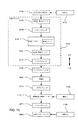
PAPデバイス110は、モータ114を有する流れ発生器又はブロワ112を含むことができ、モータ114は、加圧されたガス又は空気の供給物を生成するためにモータ114のロータ116に結合されたインペラ118を駆動するように構成される。モータ114は、プロセッサ120によって制御され、プロセッサ120は、ボリュート又は他の流れ誘導チャンバ内でロータ116が回転し、その結果インペラ118が回転する速度を制御する駆動信号をモータ114に提供する。好ましい実施形態では、モータ114は、ロータ116が回転するときのモータの逆起電力(EMF)を測定することによってモータの速度を確定することができる、ホール効果センサのないモータ等のセンサレス(例えば、転流(commutation)又は位置センサなし)モータとすることができる。プロセッサ120は、ブロワの測定速度をブロワの所望の速度と比較し、所望の速度を維持するようにモータの電圧又は電流を調整することによってモータ114を所望のモータ速度に維持するために、フィードバック制御ループを備える。幾つかの場合、本技術は、付加的なセンサなし(例えば、流量センサ及び/又は圧力センサなし)で実装することができる。
The
システム及びブロワの特性、例えば、空気送出導管に沿う圧力低下等は、好ましくは予め決定されている。そのため、モータ速度と送出される圧力との関係は既知である。その結果、PAPデバイスはブロワの速度を制御し、所望の圧力を提供する。幾つかの場合、圧力センサによって確定される実際の圧力測定値は存在しない場合がある。しかし、幾つかの場合、圧力は、既知の又は測定済みのパラメータから推定又は計算することができる。幾つかの場合、本明細書で述べる電流信号解析は、流量センサ、圧力センサ、及び/又は速度センサなしの実装態様を可能にするように、PAPデバイス又は他の呼吸圧力処置デバイスが最小検知構成(例えば、電流検知抵抗器(複数の場合もある)だけ)によって動作することを可能にすることができる。しかし、本明細書でより詳細に示すように、幾つかの場合、こうしたセンサの1つ又は複数は、装置とともに実装することができる。こうした場合、電流信号解析は、センサに基づいて動作をチェックするために冗長サイクリング若しくはトリガプロセスとして働くことができるか、又は、センサの1つ若しくは複数における故障の検出時に、バックアッププロセスとしてその他の方法で起動することができる。 System and blower characteristics, such as pressure drop along the air delivery conduit, are preferably predetermined. Therefore, the relationship between motor speed and delivered pressure is known. As a result, the PAP device controls the blower speed and provides the desired pressure. In some cases, there may not be an actual pressure measurement determined by the pressure sensor. In some cases, however, the pressure can be estimated or calculated from known or measured parameters. In some cases, the current signal analysis described herein may allow the PAP device or other respiratory pressure treatment device to have a minimal sensing configuration to allow implementation without a flow sensor, pressure sensor, and / or velocity sensor. (E.g., only current sensing resistor (s) may be allowed to operate). However, as will be shown in more detail herein, in some cases one or more of these sensors may be implemented with the device. In such cases, the current signal analysis can serve as a redundant cycling or trigger process to check operation based on the sensor, or other method as a backup process upon detection of a failure in one or more of the sensors. You can start with.
PAPデバイス110は、任意選択で、ユーザがデバイス、例えばオン/オフボタンと相互作用することを可能にする、1つ又は複数のボタン及び/又はダイアル等のユーザインタフェース122及び/又はコントロール124を含むことができる。
The
PAPデバイスは、通常、空気送出導管(図示せず)に結合されたガス出口126を含んでおり、ブロワ112によって生成される加圧されたガスの流れをマスク又は鼻組立体等の患者インタフェースユニット(図示せず)に送出する。
The PAP device typically includes a
或る例では、PAPデバイスは、呼吸サイクルの吸気フェーズ中に第1の圧力を、また、呼吸サイクルの呼気フェーズ中に第2の圧力を送出するように構成することができる。第1の圧力は第2の圧力以上である。第1の圧力と第2の圧力との圧力差は、圧補助と呼ばれ、こうした圧力差は、呼気圧力軽減(EPR)を提供するために、0cmH2O、1cmH2O、2cmH2O、又は3cmH2Oに設定することができる。PAPデバイスがバイレベルPAPデバイスであるとき、より高い圧補助値を提供することができる。好ましくは、第1の圧力は4cmH2Oと28cmH2Oとの間であり、第2の圧力は2cmH2Oと20cmH2Oとの間である。 In certain examples, the PAP device may be configured to deliver a first pressure during the inspiratory phase of the respiratory cycle and a second pressure during the expiratory phase of the respiratory cycle. The first pressure is greater than or equal to the second pressure. The pressure difference between the first pressure and the second pressure is referred to as pressure assist, and these pressure differences are used to provide expiratory pressure relief (EPR), 0 cmH 2 O, 1 cmH 2 O, 2 cmH 2 O, Or it can be set to 3 cmH 2 O. When the PAP device is a bi-level PAP device, a higher pressure assist value can be provided. Preferably, the first pressure is between 4 cmH 2 O and 28 cmH 2 O, and the second pressure is between 2 cmH 2 O and 20 cmH 2 O.
呼吸中、患者インタフェースに送出される流れは、ユーザの呼吸サイクルとともに変動することになる。流れのこうした変化は、適切な圧力を送出する所望のモータ速度にブロワを維持するために提供される電流のレベルの変化をもたらすことになる。電流のレベルのこれらの変化を使用して、起こっている流れの変化を評価し、吸気から呼気への、またその逆に、呼気から吸気への遷移を検出することができる。そのため、幾つかの実施形態では、モータの相電流ではなく、ブロワのモータのブリッジ駆動回路に供給される電流を、流れについてのプロキシとして使用することができる。 During breathing, the flow delivered to the patient interface will vary with the user's breathing cycle. Such changes in flow will result in changes in the level of current provided to maintain the blower at the desired motor speed delivering the appropriate pressure. These changes in the level of current can be used to assess the flow changes that are occurring and to detect the transition from inspiration to expiration and vice versa. Thus, in some embodiments, the current supplied to the blower motor bridge drive circuit, rather than the motor phase current, can be used as a proxy for flow.
幾つかのこうした場合において、例えば、(ブリッジ回路を介して)モータに印加される電圧がほぼ一定である可能性が高いとき、電流は、或る特定の時間における流れについてのプロキシとして働くことができる。モータを制御するための、ソース電圧(例えば、バス電圧)のパルス幅変調(PWM)の実装態様の場合、バス電圧より低いモータへの電圧が、モータに印加されることになる(例えば、印加電圧は、バス電圧にPWMパーセンテージを掛けた値に等しくすることができる)。 In some such cases, for example, when the voltage applied to the motor is likely to be approximately constant (via a bridge circuit), the current can act as a proxy for the flow at a particular time. it can. For pulse width modulation (PWM) implementations of source voltage (eg, bus voltage) to control the motor, a voltage to the motor that is lower than the bus voltage will be applied to the motor (eg, applied) The voltage can be equal to the bus voltage multiplied by the PWM percentage).
代替的に、幾つかの実施形態では、ブロワに対する電力は、流れについてのプロキシとして使用することができる。こうした場合、ブロワに対する供給電流の電流信号は、モータに対する電圧を表す信号とともに乗算器回路に提供することができる。その後、電流信号ではなく、こうした電力信号を本明細書で述べるプロセスに印加することができる。 Alternatively, in some embodiments, power to the blower can be used as a proxy for the flow. In such a case, the current signal of the supply current to the blower can be provided to the multiplier circuit along with a signal representing the voltage to the motor. Such power signals, and not current signals, can then be applied to the processes described herein.
そのため、幾つかの実施形態では、モータ電流信号を測定し、記録してもよい。任意選択で、その信号を表すサンプリング済みデータとすることができる測定済みモータ電流信号MCSは、その後、アナログ処理回路(例えば、アナログプロセッサ)、若しくはデジタル処理回路(例えば、デジタルプロセッサ)、又はこれらの任意の組合せ等のプロセッサ又は処理回路によって処理することができる。 Thus, in some embodiments, the motor current signal may be measured and recorded. The measured motor current signal MCS, which can optionally be sampled data representing that signal, is then analog processing circuitry (eg, an analog processor), or digital processing circuitry (eg, a digital processor), or these It can be processed by a processor or processing circuit such as any combination.
こうしたプロセッサ又は処理回路の一実施形態の例示的な要素が図2に示される。幾つかの場合、処理回路に印加されるモータ電流信号MCSは、1つ又は複数の電流検知抵抗器を使用して測定することができる。任意選択で、ホールセンサ、電流変圧器、プリント回路基板(PCB)トレース(抵抗器の変形)等の他のデバイスを、電流を測定するために実装することができる。電流は、モータリード線又はコモンブリッジボトム(common bridge bottom)において測定することができる。電流はまた、2つ又は3つのセンサ等によってブリッジトップ又はボトムにおいて測定することができる。幾つかの場合、測定される電流は、モータのコイルの相電流の平均とすることができる。 Exemplary elements of one embodiment of such a processor or processing circuit are shown in FIG. In some cases, the motor current signal MCS applied to the processing circuit can be measured using one or more current sensing resistors. Optionally, other devices such as Hall sensors, current transformers, printed circuit board (PCB) traces (resistor variants) can be implemented to measure current. The current can be measured at the motor lead or the common bridge bottom. The current can also be measured at the bridge top or bottom, such as by two or three sensors. In some cases, the measured current can be an average of the motor coil phase currents.
測定されるモータ電流信号MCSは、その後、1つ又は複数のフィルタ等による図2に示すフィルタリング等によって処理されて、種々の評価信号を導出することができる。例えば、測定されるモータ電流信号MCSを、ローパスフィルタ(例えば、53Hz又は160Hzカットオフ周波数を有する1次ローパスフィルタ、移動平均フィルタ、高次フィルタ、又は同様なもの)等のフィルタ202によってフィルタリングして、信号内のノイズ又は外乱を除去することができる。こうしたフィルタリングから導出される信号は、瞬時若しくは短期間モータ電流信号STC、又は電流の短期間平均測定量であると考えることができる。こうした信号は、流量センサなしで、現在の流量レベルの指示子として採用することができる。こうしたフィルタリングの選択されたパラメータ又は時定数(複数の場合もある)に基づいて、電流の短期間測定量は、1未満の平均呼吸、例えば、平均呼吸の半分未満の期間にわたるモータ電流の測定量であると考えることができる。
The measured motor current signal MCS can then be processed, such as by filtering shown in FIG. 2 with one or more filters, etc., to derive various evaluation signals. For example, the measured motor current signal MCS is filtered by a
長期モータ電流信号LTCはまた、図2に示す更なるフィルタ206等によるフィルタリングによって導出することができる。例えば、短期モータ電流信号STCは、ローパスフィルタ(例えば、0.003Hzカットオフ周波数を有する1次ローパスフィルタ、移動平均フィルタ、高次フィルタ、又は同様なもの)等のフィルタ206によってフィルタリングすることができる。こうした処理によって導出される信号は、漏れ等によるベース流量レベルの指示として採用することができる。漏れは、患者インタフェースからの故意の漏れ及び/又はシステムに関するフィッティング問題による他の漏れを含む場合がある。したがって、フィルタリングのパラメータ又は時定数(複数の場合もある)に基づいて、長期モータ電流信号LTCは、単一の呼吸より長い所定の期間にわたる電流の測定量であると考えることができる。したがって、LTCはまた、電流の長期平均測定量であると考えることができる。例えば、LTCは、4回、5回、6回、7回、又は8回の呼吸等の2回〜10回の呼吸の範囲内等で複数回の呼吸の継続時間にわたって導出することができる。代替的に、所定の期間は、所定の数の以前の電流値を記録するのにかかる時間を含むことができる。又は、先行する所定の秒数、例えば、30秒以上等の先行する10秒〜90秒、15秒〜50秒、20秒〜40秒にわたって記録される電流値等の時間ベース限界として設定することができる。しかし、長期モータ電流についての他の期間を利用することができることが理解されるべきである。
The long-term motor current signal LTC can also be derived by filtering, such as with the
デジタル処理の場合、モータ電流又はそのモータ電流のフィルタリングからの導出信号は、5Hz等の1KHz〜20KHzのサンプリングレートでサンプリングすることができる。そのため、幾つかの場合、長期又は短期の導出測定量は、サンプリングデータによって相応して計算することができる。しかし、他のサンプリングレートを実装することができることを当業者は理解するであろう。 For digital processing, the motor current or the derived signal from the filtering of the motor current can be sampled at a sampling rate of 1 KHz to 20 KHz, such as 5 Hz. Thus, in some cases, long-term or short-term derived measurements can be correspondingly calculated with sampling data. However, those skilled in the art will appreciate that other sampling rates can be implemented.
任意選択で、本技術の幾つかの実施形態では、吸気フェーズと呼気フェーズとの間の圧力を変更するための速度の変化中等、モータによる既知の速度変化中、フィルタリングの計算は、こうした変化に関連する電流をフィルタに印加することを回避するため調整することができる。例えば、長期モータ電流信号を導出するためのフィルタリングは、こうした変化に基づいて休止又は一時的に停止することができる。代替的に、こうした変化中に得られる電流値は、長期測定量の計算から排除することができる。 Optionally, in some embodiments of the technology, during known speed changes by the motor, such as during a speed change to change the pressure between the inspiratory phase and the expiratory phase, the filtering calculation may account for these changes. Adjustments can be made to avoid applying an associated current to the filter. For example, filtering to derive a long-term motor current signal can be paused or temporarily stopped based on such changes. Alternatively, current values obtained during these changes can be excluded from long-term measurement calculations.
なおさらに、幾つかのバージョンでは、モータ速度の故意の/既知の変化中にフィルタの状態を維持するために、実際のモータ電流の値又は実際のモータ電流に基づく値ではなく、フィルタのコンテンツ(例えば、フィルタの長期平均)に正味の値を全く付加しないように計算される数値定数とすることができるメンテナンス値又は「ブランキング値(blanking value)」を、任意選択で、フィルタリングに適用することができる。例えば、モータ加速/減速メンテンス因子は、モータによるこうした既知の速度変化中にフィルタ206に適用することができる。こうした処理の例は、図2を参照して考えることができる。切換え又は決定要素205は、短期モータ電流STC、又は、メンテナンス信号発生器204若しくは他のバッファからのメンテナンス信号をフィルタ206に選択的に適用することができる。こうした切換え要素についての条件又はロジックは、本明細書でより詳細に論じられる。
Still further, in some versions, to maintain the state of the filter during deliberate / known changes in motor speed, the filter content (rather than the actual motor current value or a value based on the actual motor current) A maintenance value or “blanking value”, which can be a numerical constant calculated to add no net value to the long-term average of the filter), for example, is optionally applied to the filtering. Can do. For example, a motor acceleration / deceleration maintenance factor can be applied to the
呼吸の異なるフェーズを検出する等のため流量の変化を判断するために、瞬時又は短期モータ電流STCは、長期モータ電流LTCと比較することができる。こうした比較は、吸気又は呼気の指示子又は信号IES等の呼吸流量の変化の指示を提供するのに役立つことができる。こうした処理の例は、図2の比較器要素212を参照して考えることができる。例えば、瞬時又は短期モータ電流が長期モータ電流より大きいとき、比較は、流量が増加しているという指示(indication)として採用することができる。瞬時又は短期モータ電流が長期モータ電流より小さいとき、比較は、流量が減少しているという指示として採用することができる。こうした増加する流量は、吸気が起こっているという指示として働くことができ、こうした減少する流量は、呼気が起こっているという指示として働くことができる。そのため、患者の呼吸サイクルの異なるフェーズ、吸気及び呼気の開始は、長期電流と比較される瞬時又は短期電流の変化のこの評価に基づいて流量の変化をモニタすることによって判断することができる。呼吸の異なるフェーズの開始の検出が使用されて、異なる呼吸フェーズについて送出される圧力を必要に応じて変化させるためモータ速度を変更するモータ制御プロセッサ等のための、トリガ及び/又はサイクリング信号を提供することができる。例えば、比較に基づいて、比較器212は、呼気の場合に正の信号又は高い信号を生成し、吸気の場合にヌル信号又は低い信号を生成する(又はその逆)ように構成することができる。このとき、正のIES信号は、呼気圧力用のブロワの速度変化を設定する制御信号として働くことができる。このとき、ヌル信号又は低いIES信号は、吸気圧力用のブロワの別の速度変化を設定する制御信号として働くことができる。
The instantaneous or short-term motor current STC can be compared to the long-term motor current LTC to determine changes in flow rate, such as to detect different phases of respiration. Such a comparison can help provide an indication of changes in respiratory flow, such as an inspiration or expiration indicator or signal IES. An example of such processing can be considered with reference to the
幾つかの実施形態では、補償因子が、任意選択で実装されて、患者の呼吸サイクルのフェーズ変化を電流から判断することと、送出される圧力を変更するようにモータ速度を調整することとの間の遅延又はラグを補償することができる。それにより、補償因子の実装は、IES信号でモータ速度(及び結果として生じる圧力)を少し早期に調整させることができ、それにより、モータ速度の実際の変化は、患者又はユーザの呼吸サイクルの変化と同期する可能性が高くなる。こうした実施形態は、補償発生器210−1、210−2、及び加算器208等のコンバイナ要素を示す図2を参照して考えることができる。この例では、加算器208は、IES信号の状態に基づいて発生器又はバッファからの補償信号を選択的に加算する。切換え又は決定要素211は、複数の信号発生器210−1、210−2(1つ又は複数のバッファ等)からの異なる補償信号を加算器208に選択的に印加することができる。こうした切換え要素用の条件又はロジックは、切換え制御要素218を参照して本明細書でより詳細に論じられる。本質的に、切換え制御要素218は、IES信号(又は検出される吸気若しくは呼気の状態)に基づいて、切換え又は決定要素211を制御して、図3の状態機械を参照して本明細書で論じる時間に、長期モータ電流信号に正又は負の補償因子を適用することができる。
In some embodiments, a compensation factor is optionally implemented to determine the phase change of the patient's respiratory cycle from the current and adjust the motor speed to change the delivered pressure. The delay or lag between can be compensated. Thereby, the implementation of the compensation factor can cause the motor speed (and the resulting pressure) to be adjusted a little earlier with the IES signal, so that the actual change in motor speed is a change in the patient or user's breathing cycle. Is more likely to synchronize with. Such an embodiment can be considered with reference to FIG. 2, which shows combiner elements such as compensation generators 210-1, 210-2, and
補償因子を使用するシステムでは、瞬時又は短期モータ電流は、長期モータ電流に対し補償因子を加算又は減算したものを表す調整済み長期モータ電流と比較される。こうした場合、瞬時又は短期モータ電流が長期モータ電流から補償因子を減算した値より小さい場合、比較器212は、呼気を示すIES信号を生成することになり、それにより、モータ速度を、IES信号に応答して、呼気圧力モータ速度に調整することができる。同様に、瞬時又は短期モータ電流が長期モータ電流に補償因子を加算した値より大きい場合、比較器212は、吸気を示すIES信号を生成することになり、それにより、モータ速度を、IES信号に応答して、吸気圧力モータ速度に調整することができる。
In systems that use compensation factors, the instantaneous or short-term motor current is compared to an adjusted long-term motor current that represents the long-term motor current plus or minus the compensation factor. In such a case, if the instantaneous or short-term motor current is less than the long-term motor current minus the compensation factor, the
幾つかの実施形態では、補償因子(CF)は、電流の設定済みバッファレベル、例えば2mA〜10mAとすることができる。代替の配置構成では、補償因子は、長期モータ電流の分数又はパーセンテージ等の比率として自動的に確定することができる。更なる配置構成では、補償因子は、吸気及び/又は呼気フェーズ中の電流の検出されるピークの関数として計算することができる。こうした配置構成では、吸気及び/又は呼気フェーズ中のピーク電流が検出され、補償因子は、ピーク値の比率(例えば、分数又はパーセンテージ)として確定される。代替の配置構成では、補償因子は、最後のIES遷移以来の時間に基づいて確定することができる。 In some embodiments, the compensation factor (CF) can be a set buffer level of current, eg, 2 mA to 10 mA. In an alternative arrangement, the compensation factor can be automatically determined as a ratio, such as a fraction or percentage of the long-term motor current. In a further arrangement, the compensation factor can be calculated as a function of the detected peak of the current during the inspiration and / or expiration phase. In such an arrangement, the peak current during the inspiration and / or expiration phase is detected and the compensation factor is determined as a ratio of peak values (eg fractions or percentages). In an alternative arrangement, the compensation factor can be determined based on the time since the last IES transition.
図2に更に示すように、比較器212のIES信号出力は、任意選択で、切換え又は決定要素213、バッファ216、及びエッジ起動式ブランキングタイマ214に印加することができる。IES信号の最新の状態は、バッファ216内に保持され、このバッファから切換え又は決定要素213に出力することができる。そのため、切換え又は決定要素213は、比較器からのIES信号の電流状態又はバッファ216からのIES信号の以前のものであるが最新の状態を選択的に出力することになる。この点に関して、エッジ起動式ブランキングタイマ214は、切換え又は決定要素213用の制御信号CSを生成することになる。エッジ起動式ブランキングタイマ214のプロセスは、比較器から出力されるIES信号の変化を検出するエッジ検出器を含むことになる。エッジの検出は、その後、所定の時間間隔を有するタイマを始動することができる。所定の時間間隔中に、エッジ起動式ブランキングタイマ214は、比較器からのIES信号ではなく、バッファ216内に保持されるIES信号の直前で最新の状態を選択するよう、切換え又は決定要素213を設定する制御信号を出力することになる。他の時間では、エッジ起動式ブランキングタイマ214は、バッファ216内に保持されるIES信号の以前のものであるが最新の状態ではなく、比較器からのIES信号を選択するよう、切換え又は決定要素213を設定する制御信号CSを出力することになる。こうした制御は、吸気圧力用の吸気速度設定と呼気圧力用の呼気速度設定との間でモータが変化しているとき等、モータの速度が変化する時間中に、より安定したIES信号を可能にすることができる。したがって、モータ速度の上述した変化に関連する典型的な時間に等しいか又はそれを超える時間量の間、バッファ216の出力をIES信号として使用するように、エッジ起動式ブランキングタイマ214のタイミング間隔の所定の時間を選択することができる。
As further shown in FIG. 2, the IES signal output of the
さらに、メンテナンス信号発生器204を参照して上記で述べたように、エッジ起動式ブランキングタイマ214によって出力される制御信号CSは、切換え又は決定要素205を制御するために印加することができる。この点に関して、フィルタ206への入力は、メンテナンス信号発生器204の出力に選択的に変更することができる。そのため、エッジ起動式ブランキングタイマ214は、エッジ起動式ブランキングタイマ214のタイミング間隔の所定の時間の間、フィルタに対するメンテンス信号の印加を選択的に制御することができる。そのため、フィルタ206は、吸気速度設定及び/又は呼気速度設定に関連する変化等のモータ速度の変化に関連する通常の時間に等しいか又はそれを超える時間量の間、メンテンス信号の出力を受信することができる。他の時間では、切換え又は決定要素205は、エッジ起動式ブランキングタイマ214の制御下で、短期間電流がフィルタ206に印加されることを可能にすることができる。
Further, as described above with reference to the
図3は、モータ速度、その結果、ブロワによって送出される圧力を制御するモータ速度コントローラについての例示的な状態機械の略図である。状態1、302では、モータは、モータ速度を呼気モータ速度に設定するコマンド信号を提供される。上記で述べたように、減速に起因する電流の変化を補償するために、この速度遷移フェーズ中の電流値の記録を休止又は一時的に停止してもよく、又は、減速メンテナンス因子をフィルタリングプロセスについて適用してもよい。呼気モータ速度に達する(それは、所望の速度と測定若しくは推定される速度との比較又は所定の期間の経過に基づいて判定することができる)と、モータ速度コントローラは、状態2、304に移動し、そこで、短期間モータ電流(STC)が長期間モータ電流(LTC)に補償因子(CF)を加算したものより大きくなる時間まで呼気圧力を維持するように運転し続けるようモータにシグナリングする。短期間電流(STC)が長期間電流(LTC)に補償因子(CF)を加算したものより大きくなると、モータ速度コントローラは、状態3、306に遷移し、モータ速度を吸気モータ速度まで増加させるコマンド信号がモータに送信される。やはり上記で述べたように、この状態の間、この速度遷移フェーズ中の電流値の記録を、休止又は一時的に停止することができるか、又は、加速メンテナンス因子をフィルタリングプロセスについて利用して、加速に起因する電流の変化を補償することができる。設定された吸気モータ速度に達する(それは、所望の速度と測定若しくは推定される速度との比較、又は所定の期間の経過に基づいて判定することができる)と、モータ速度コントローラは、状態4、308に遷移する。状態4、308の間、短期間電流(STC)が長期間電流(LTC)から補償因子(CF)を減算したものより小さくなる時間まで吸気圧力モータ速度を維持するように運転し続けるようモータにシグナリングする。短期間電流(STC)が長期間電流(LTC)から補償因子(CF)を減算したものより小さくなると、モータ速度コントローラは、元の状態1、302に遷移し、サイクルが継続する。
FIG. 3 is a schematic diagram of an exemplary state machine for a motor speed controller that controls the motor speed and consequently the pressure delivered by the blower. In
或る特定のオプションの配置構成では、モータコントローラは、状態1、302と状態2、304との間に更なる状態1.5、303を含むことができる。状態1.5、303では、短期間電流(STC)が長期間電流(LTC)と比較される前に、所定の呼気圧力遅延が設定される。こうした遅延は、最小期間の間、呼気が起こることを保証し、及び/又は、状態2、304から状態3、306に入るようにする偽りのトリガが回避されることを保証することができる。更なる配置構成(図示せず)では、同様な吸気圧力遅延状態3.5を状態306と状態308との間に付加して、最小期間の間、吸気が起こることを可能にすることを保証することができる。
In certain optional arrangements, the motor controller may include additional states 1.5, 303 between
或る特定の例では、モータは、送出される圧力を吸気モータ速度から呼気モータ速度まで変更するモータ速度の変化について能動制動が起こらないように、フリーホイールすることを可能にすることができる。モータを減速させるためのフリーホイールは、米国特許出願公開第2007/0017518号に記載される方法又は装置を使用することができる。この特許文献の開示は、引用することによりその全体が本明細書の一部をなすものとする。代替的に、モータの或る形態の制動を利用して、吸気と呼気との間の遷移を制御することができる。 In one particular example, the motor may allow freewheeling so that active braking does not occur for changes in motor speed that change the delivered pressure from inspiratory motor speed to expiratory motor speed. The freewheel for decelerating the motor can use the method or apparatus described in US Patent Application Publication No. 2007/0017518. The disclosure of this patent document is incorporated herein by reference in its entirety. Alternatively, some form of braking of the motor can be utilized to control the transition between inspiration and expiration.
或る特定のシステムでは、治療を最初に開始するとき、第2の所定の期間が過ぎてしまうまで、長期モータ電流を計算するときの遅延が存在する場合がある。或る特定の例では、第2の所定の期間は、少なくとも長期平均電流を計算するときに使用される程度の長い所定の期間とすることができる。遅延は、ユーザが治療の開始に順応し、デバイスが電流値を記録し始めるためのセトリング時間を提供することができる。デバイスは、このセトリング時間中に吸気と呼気の両方の間に単一の一定圧力(すなわち、単一の設定モータ速度)を提供するように構成することができる。 In certain systems, when treatment is first started, there may be a delay in calculating the long-term motor current until the second predetermined period has passed. In one particular example, the second predetermined period may be a predetermined period that is at least as long as is used when calculating the long-term average current. The delay can provide a settling time for the user to adapt to the start of treatment and for the device to begin recording current values. The device can be configured to provide a single constant pressure (ie, a single set motor speed) during both inspiration and expiration during this settling time.
代替的に、長期モータ電流は、最初に、所定の初期平均電流値に設定することができる。所定の初期平均電流値は、製造中のシステムの事前特徴付けによってデバイス内に予め設定してもよいし、又は、直前の治療セッションからの長期平均電流に基づいて設定してもよい。付加的に又は代替的に、或る特定の例示的なデバイスでは、所定の期間は、最初に、治療の開始時(例えば、治療の最初の1分〜2分の間)に(例えば、10秒、15秒、又は20秒に)短縮されて、長期平均電流のより速い計算を提供することができる。こうしたデバイスでは、電流値は、治療が開始されるとすぐに記録されて、異なる呼吸フェーズ中に圧力に対して調整を行なって又は行うことなく、異なる呼吸フェーズを検出するため流れの変化を評価することができる。 Alternatively, the long-term motor current can be initially set to a predetermined initial average current value. The predetermined initial average current value may be preset in the device by pre-characterization of the system being manufactured, or may be set based on a long-term average current from the previous treatment session. Additionally or alternatively, in certain exemplary devices, the predetermined period of time is initially at the start of treatment (eg, between the first 1-2 minutes of treatment) (eg, 10 (Seconds, 15 seconds, or 20 seconds) can provide a faster calculation of the long-term average current. In such devices, the current value is recorded as soon as treatment is initiated, and the change in flow is evaluated to detect different breathing phases with or without adjustment for pressure during the different breathing phases. can do.
図2に示さないが、幾つかの実施形態では、付加的な「観測器(observer)」プロセスコンポーネントを含むことができる。観測器は、設計時にわかっているシステムパラメータ(モータトルク定数、システム慣性等)に基づいて、圧力変化中のモータの加速/減速による、モータに供給される電流の部分を推定するように構成することができる。この推定によって、電流は、本明細書で述べるフィルタリングの前に調整することができる。したがって、(長期モータ電流を減算した後の)患者の流れを示す短期モータ電流は、吸気又は呼気のより単純な指示ではなく、患者の呼吸の流れの状態のより連続的な指示子として採用することができる。こうした信号は、その後、単純な2重レベル制御指示子と対照的に、患者の呼吸サイクル内でより連続的な方式で処置圧力に対する変更を制御するための基礎として働くことができる。 Although not shown in FIG. 2, in some embodiments, additional “observer” process components may be included. The observer is configured to estimate the portion of current supplied to the motor due to acceleration / deceleration of the motor during pressure changes based on system parameters known at design time (motor torque constant, system inertia, etc.). be able to. With this estimation, the current can be adjusted prior to the filtering described herein. Thus, the short-term motor current indicative of the patient flow (after subtracting the long-term motor current) is employed as a more continuous indicator of the patient's respiratory flow status rather than a simpler indication of inspiration or expiration. be able to. Such signals can then serve as a basis for controlling changes to the treatment pressure in a more continuous manner within the patient's respiratory cycle, as opposed to a simple dual level control indicator.
更なる例として、処理回路が図2の回路要素として示されているが、これらの要素のプロセスを、デジタルプロセッサのアルゴリズム又は処理によって実装してもよいことが理解されるであろう。こうした場合、デジタルプロセッサは、集積化チップ、メモリ、及び/又は、他の制御命令、データ若しくは情報記憶媒体を含むことができる。例えば、プロセス方法を包含するプログラムされた命令は、メモリ内の集積化チップ上でコード化してもよいし、又はその他の方法で、特定用途向け集積化チップ(ASIC)を形成してもよい。こうした命令は、同様に又は代替的に、適切なデータ記憶媒体を使用してソフトウェア又はファームウェアとしてロードしてもよい。 As a further example, although processing circuitry is shown as the circuit elements of FIG. 2, it will be understood that the processes of these elements may be implemented by digital processor algorithms or processes. In such cases, the digital processor may include integrated chips, memory, and / or other control instructions, data, or information storage media. For example, programmed instructions including process methods may be encoded on an integrated chip in memory, or otherwise form an application specific integrated chip (ASIC). Such instructions may similarly or alternatively be loaded as software or firmware using a suitable data storage medium.
例示的なシステムアーキテクチャ
本技術に適するこうしたコントローラの例示的なシステムアーキテクチャが図4のブロック図に示される。図において、呼吸処置装置用の本明細書で述べるモータ電流解析プロセスを有するコントローラ401は、1つ又は複数のプロセッサ408を含むことができる。システムはまた、モニタ又はLCDパネル等の上に、本明細書で述べるように事象(例えば、吸気又は呼気等)検出レポートを出力するディスプレイインタフェース410を含むことができる。例えば、キーボード、タッチパネル、制御ボタン、マウス等用のユーザ制御/入力インタフェース412もまた設けられて、本明細書で述べる制御方法をアクティブ化又は修正することができる。システムはまた、プログラミング命令、電流信号、速度信号、逆EMF信号、モータ制御信号等のデータを受信/送信するための、バス等のセンサ又はデータインタフェース414を含むことができる。デバイスはまた、通常、上述した方法(例えば、図2及び図3)の制御命令を含むメモリ/データ記憶コンポーネント420を含むことができる。これらは、422の、モータ電流信号処理(例えば、前処理方法、フィルタ、値発生器、ブランキング又はメンテナンス値発生ロジック、タイマ、補償発生ロジック、観測器プロセス、エッジ検出器等)用のプロセッサ制御命令を含むことができる。これらはまた、本明細書でより詳細に論じる424の、モータ電流信号処理に基づく処置制御(例えば、処置変更、速度制御等)用のプロセッサ制御命令を含むことができる。最後に、それらはまた、フィルタ時定数、フィルタパラメータ、ブランキング値、メンテナンス値、補償値、処置設定、圧力対速度設定テーブル等の、これらの方法のための記憶されたデータ426を含むことができる。幾つかの実施形態では、ソフトウェアを汎用コンピュータにロードすると、汎用コンピュータが本明細書で論じる方法のうちの任意の方法に従う専用コンピュータとして働くことができるよう、上述した方法を制御するための、これらのプロセッサ制御命令及びデータを、汎用コンピュータが使用するためのソフトウェアとしてコンピュータ可読記録媒体に収容してもよい。
Exemplary System Architecture An exemplary system architecture of such a controller suitable for the present technology is shown in the block diagram of FIG. In the figure, a
例示的な呼吸処置装置
1.1 処置システム
一形態では、本技術は、図5及び図7aに示すもの等の、呼吸障害を処置する装置の一部を形成することができる。この装置は、空気等の加圧呼吸ガスを、患者インタフェース3000に通じる空気送達チューブを介して患者1000に供給するためのフロージェネレータ又はブロワを備えることができる。
Exemplary Respiratory Treatment Device 1.1 Treatment System In one form, the present technology may form part of a device for treating respiratory disorders, such as those shown in FIGS. 5 and 7a. The device may comprise a flow generator or blower for supplying pressurized breathing gas, such as air, to the
1.2 治療
一形態では、本技術は、一方又は両方の鼻孔及び/又は口を介して、患者1000の気道の入口、例えば患者の鼻腔等に、陽圧を印加するステップを含む、呼吸障害を処置するための方法の一部として働くことができる。例えば、PAPデバイス4000は、鼻持続気道陽圧(Continuous Positive Airway Pressure:CPAP)治療を生成して、後口咽頭壁の前方にかつそこから離れるように軟口蓋及び舌を押すことによって上気道の閉塞性睡眠時無呼吸(Obstructive Sleep Apnea:OSA)を処置することができる。
1.2 Treatment In one form, the technique involves applying positive pressure to one or both nostrils and / or mouth to the entrance of the airway of the
PAPデバイス4000は、CSR、OHS、COPD、MD、及び胸壁障害を処置するために使用されてきた非侵襲的換気(Non-invasive ventilation:NIV)を生成することができる。NIVの幾つかの例では、圧力処置は、例えば1回換気量又は毎分換気量を測定し、ターゲット換気を満たすように換気の測定量を制御することによってターゲット換気を実施ように制御することができる。換気の瞬時測定量と換気の長期測定量との比較等による換気の測定量のサーボ制御は、CSRに抗する処置として働くことができる。幾つかのこうした例では、装置によって送出される圧力処置の形態は、圧補助換気とすることができる。こうした圧力処置は、通常、吸気中のより高いレベルの圧力(例えば、IPAP)の生成を、また、呼気中のより低いレベルの圧力(例えば、EPAP)の生成を提供する。
The
1.3 患者インタフェース3000
図6に示すように、本技術の一態様による非侵襲的患者インタフェース3000は、以下の機能的態様、すなわち、シール形成構造3100、プレナムチャンバ3200、位置決め及び安定化構造3300、及び空気回路4170に接続するための接続ポート3600を含むことができる。幾つかの形態では、機能的態様は、1つ又は複数の物理構成要素によって提供することができる。幾つかの形態では、1つの物理構成要素は、1つ又は複数の機能的態様を提供することができる。使用の際、シール形成構造体3100は、気道への陽圧の空気の供給を容易にするために、患者の気道への入口を取り囲むように配置される。
1.3
As shown in FIG. 6, a
1.4 PAPデバイス4000
図7a、7b及び7cに示されるように、本技術の1つの態様による例示的なPAPデバイス4000は、機械構成要素及び空気圧構成要素4100、電気構成要素4200を備えることができ、1つ又は複数のアルゴリズムを実行するようにプログラムすることができる。このPAPデバイスは、外部ハウジング4010を有することができる。外部ハウジング4010は、外部ハウジング4010の上側部分4012及び外部ハウジング4010の下側部分4014の2つの部分で形成される。代替の形態では、外部ハウジング4010は、1つ又は複数のパネル4015を備えることができる。PAPデバイス4000は、PAPデバイス4000の1つ又は複数の内部構成要素を支持するシャーシ4016を備えることができる。1つの形態では、空気圧ブロック(pneumatic block)4020が、シャーシ4016によって支持されるか、又はその一部分として形成される。PAPデバイス4000は、取っ手4018を備えることができる。
1.4
As shown in FIGS. 7a, 7b, and 7c, an
PAPデバイス4000の空気経路は、吸入口エアフィルタ4112、吸入口マフラ4122、陽圧の空気を供給することが可能な制御可能圧力デバイス4140(好ましくは、ブロワ4142)、及び放出口マフラ4124を備えることができる。1つ又は複数の圧力センサ(例えば、圧力トランスデューサ4272)及び流量センサ(例えば、流量トランスデューサ4274)を、任意選択で空気経路に備えることができる。
The air path of the
空気圧ブロック4020は、空気経路のうちの、外部ハウジング4010内に位置する部分を含む。
PAPデバイス4000は、電源装置4210、1つ又は複数の入力デバイス4220、中央コントローラ4230、療法デバイスコントローラ4240、療法デバイス4245、1つ又は複数の保護回路4250、メモリ4260、選択的トランスデューサ4270、データ通信インタフェース4280、及び1つ又は複数の出力デバイス4290を有する。電気構成要素4200は、単一のプリント回路基板アセンブリ(PCBA)4202上に実装することができる。代替の形態では、PAPデバイス4000は、2つ以上のPCBA4202を備えることができる。
PAPデバイス4000の中央コントローラ4230は、1つ又は複数のアルゴリズムモジュールを実行するようにプログラムすることができる。これらのアルゴリズムモジュールは、1つの実施態様では、前処理モジュール、療法エンジンモジュール、圧力制御モジュール、及び故障状態モジュールを含む。
The
以下では、PAPデバイス4000は、人工呼吸器と区別することなく呼ばれる。
In the following, the
1.4.1 PAPデバイスの機械構成要素及び空気圧構成要素4100
1.4.1.1 エアフィルタ(複数の場合もある)4110
本技術の1つの形態によるPAPデバイスは、1つのエアフィルタ4110、又は複数のエアフィルタ4110を備えることができる。
1.4.1 Mechanical and pneumatic components 4100 of the PAP device
1.4.1.1 Air filter (s) 4110
A PAP device according to one form of the present technology may include one
1つの形態では、吸入口エアフィルタ4112は空気経路の開始部において、ブロワ4142の上流に位置している。図7bを参照されたい。
In one form, the
1つの形態では、放出口エアフィルタ4114、例えば抗菌性フィルタは、空気圧ブロック4020の放出口と患者インタフェース3000との間に位置している。図7bを参照されたい。
In one form, an outlet air filter 4114, eg, an antibacterial filter, is located between the outlet of the
1.4.1.2 マフラ(複数の場合もある)4120
本技術の1つの形態では、吸入口マフラ4122は、空気経路においてブロワ4142の上流に位置している。図7bを参照されたい。
1.4.1.2 Muffler (several cases) 4120
In one form of the present technology, the inlet muffler 4122 is located upstream of the
本技術の1つの形態では、放出口マフラ4124は、空気経路においてブロワ4142と患者インタフェース3000との間に位置している。図7bを参照されたい。
In one form of the present technology, the outlet muffler 4124 is located between the
1.4.1.3 圧力デバイス4140
本技術の1つの形態では、陽圧の空気の流量を生成するための圧力デバイス4140は、制御可能ブロワ4142である。例えば、このブロワは、ボリュート内に収容された1つ又は複数のインペラを有するブラシレスDCモータ4144を備えることができる。ブロワは、約4cmH2O〜約20cmH2Oの範囲、又は他の形態では約30cmH2Oまでの陽圧の空気の供給を、例えば約120リットル/分で送達することが可能である。
1.4.1.3
In one form of the present technology, the
圧力デバイス4140は、療法デバイスコントローラ4240の制御下にある。
1.4.1.4 トランスデューサ(複数の場合もある)4270
本技術の1つの形態では、1つ又は複数のトランスデューサ4270が、圧力デバイス4140の上流に位置することができる。この1つ又は複数のトランスデューサ4270は、空気経路のその地点における空気の性質を測定するように構成及び準備されている。
1.4.1.4 Transducer (s) 4270
In one form of the present technology, one or
本技術の1つの形態では、1つ又は複数のトランスデューサ4270は、圧力デバイス4140の下流であって、空気回路4170の上流に位置する。この1つ又は複数のトランスデューサ4270は、空気経路のその地点における空気の性質を測定するように構成及び準備されている。
In one form of the present technology, the one or
本技術の1つの形態では、1つ又は複数のトランスデューサ4270は、患者インタフェース3000に近接して位置する。
In one form of the present technology, one or
1.4.1.5 アンチスピルバック弁(anti-spill back valve)4160
本技術の1つの形態では、アンチスピルバック弁が、加湿器5000と空気圧ブロック4020との間に位置している。このアンチスピルバック弁は、水分が加湿器5000から例えばモータ4144へ上流に向けて流れる危険性を低減するように構成及び準備されている。
1.4.1.5
In one form of the present technology, an anti-spillback valve is located between the
1.4.1.6 空気回路4170
本技術の一態様による空気回路4170は、空気圧ブロック4020と患者インタフェース3000との間での空気又は呼吸可能ガスの流れを可能にするように構成及び準備されている。
1.4.1.6
The
1.4.1.7 酸素送達
本技術の1つの形態では、補助酸素4180を、空気経路における或る地点に送達することができる。
1.4.1.7 Oxygen Delivery In one form of the present technology,
本技術の1つの形態では、補助酸素4180は、空気圧ブロック4020の上流に送達される。
In one form of the present technology,
本技術の1つの形態では、補助酸素4180は、空気回路4170に送達される。
In one form of the present technology,
本技術の1つの形態では、補助酸素4180は、患者インタフェース3000に送達される。
In one form of the present technology,
1.4.2 PAPデバイスの電気構成要素4200
1.4.2.1 電源装置4210
本技術の1つの形態では、電源装置4210は、PAPデバイス4000の外部ハウジング4010の内部にある。本技術の別の形態では、電源装置4210は、PAPデバイス4000の外部ハウジング4010の外部にある。
1.4.2 PAP device
1.4.2.1
In one form of the present technology, the
本技術の1つの形態では、電源装置4210は、電力をPAPデバイス4000のみに提供する。本技術の別の形態では、電源装置4210は、電力をPAPデバイス4000及び加湿器5000の双方に提供する。
In one form of the present technology, the
1.4.2.2 入力デバイス4220
本技術の1つの形態では、PAPデバイス4000は、人がこのデバイスとインタラクトすることを可能にするボタン、スイッチ、又はダイアルの形態の、1つ又は複数の入力デバイス4220を備える。これらのボタン、スイッチ、又はダイアルは、物理デバイスとすることもできるし、タッチスクリーンを介してアクセス可能なソフトウェアデバイスとすることもできる。これらのボタン、スイッチ、又はダイアルは、1つの形態では、外部ハウジング4010に物理的に接続することもできるし、別の形態では、中央コントローラ4230に電気接続されている受信機と無線通信することもできる。
1.4.2.2
In one form of the present technology, the
1つの形態では、入力デバイス4220は、人が値及び/又はメニュー選択肢を選択することを可能にするように構成及び準備することができる。
In one form, the
1.4.2.3 中央コントローラ4230
本技術の1つの形態では、中央コントローラ4230は、x86INTELプロセッサ等の、PAPデバイス4000を制御するのに好適なプロセッサである。
1.4.2.3
In one form of the present technology, the
本技術の別の形態による、PAPデバイス4000を制御するのに好適なプロセッサは、ARM Holdings社が提供しているARM Cortex−Mプロセッサに基づくプロセッサを含む。例えば、ST MICROELECTRONICS社が提供しているSTM32シリーズのマイクロコントローラを用いることができる。
Suitable processors for controlling the
本技術の更に代替の形態による、PAPデバイス4000を制御するのに好適な別のプロセッサは、ARM9ベースの32ビットRISC CPUファミリから選択されたメンバを含む。例えば、ST MICROELECTRONICS社が提供しているSTR9シリーズのマイクロコントローラを用いることができる。本技術の或る特定の代替の形態では、16ビットRISC CPUをPAPデバイス4000用のプロセッサとして用いることができる。例えば、TEXAS INSTRUMENTS社によって製造されたMSP430ファミリのマイクロコントローラからのプロセッサを用いることができる。
Another processor suitable for controlling the
プロセッサは、1つ又は複数のトランスデューサ4270及び1つ又は複数の入力デバイス4220から入力信号(複数の場合もある)を受信するように構成されている。
The processor is configured to receive input signal (s) from one or
プロセッサは、出力デバイス4290、療法デバイスコントローラ4240、データ通信インタフェース4280、及び加湿器コントローラ5250のうちの1つ又は複数に出力信号(複数の場合もある)を提供するように構成されている。
The processor is configured to provide output signal (s) to one or more of
プロセッサ、又は複数のそのようなプロセッサは、メモリ4260に記憶されたコンピュータプログラムとして表された1つ又は複数のアルゴリズム等の本明細書において説明する1つ又は複数の方法論を実施するように構成することができる。幾つかの場合には、前に論述したように、そのようなプロセッサ(複数の場合もある)は、PAPデバイス4000と統合することができる。しかしながら、幾つかのデバイスでは、プロセッサ(複数の場合もある)は、呼吸治療の送達を直接制御することなく、本明細書において説明する方法論のうちの任意のものを実行する等の目的で、PAPデバイスの流量生成構成要素とは別個に実装することができる。例えば、そのようなプロセッサは、本明細書において説明するセンサのうちの任意のもの等からの記憶されたデータの解析によって、人工呼吸器又は他の呼吸関連事象の制御設定を決定する目的で、本明細書において説明する方法論のうちの任意のものを実行することができる。
A processor, or a plurality of such processors, is configured to implement one or more methodologies described herein, such as one or more algorithms represented as computer programs stored in
1.4.2.4 クロック4232
好ましくは、PAPデバイス4000は、プロセッサに接続されたクロック4232を備える。
1.4.2.4
Preferably,
1.4.2.5 療法デバイスコントローラ4240
本技術の1つの形態では、療法デバイスコントローラ4240は、プロセッサによって実行されるアルゴリズムの一部分を形成する圧力制御モジュールである。
1.4.2.5
In one form of the present technology, the
本技術の1つの形態では、療法デバイスコントローラ4240は、専用化されたモータ制御集積回路を含むことができる。例えば、1つの形態では、ONSEMI社によって製造されたMC33035ブラシレスDCモータコントローラが用いられる。幾つかの実施形態では、治療デバイスコントローラ4240は、治療デバイス4245のモータのブリッジ回路に結合することができる図2のコンポーネントの1つ又は複数を含むことができる。
In one form of the present technology,
1.4.2.6 保護回路4250
任意選択で、本技術によるPAPデバイス4000は、1つ又は複数の保護回路4250を備える。
1.4.2.6
Optionally, a
本技術による保護回路4250の1つの形態は、電気保護回路である。
One form of
本技術による保護回路4250の1つの形態は、温度安全回路又は圧力安全回路である。
One form of
1.4.2.7 メモリ4260
本技術の1つの形態によれば、PAPデバイス4000は、メモリ4260、好ましくは不揮発性メモリを備える。幾つかの形態では、メモリ4260は、バッテリ駆動スタティックRAMを含むことができる。幾つかの形態では、メモリ4260は、揮発性RAMを含むことができる。
1.4.2.7
According to one form of the present technology, the
好ましくは、メモリ4260は、PCBA4202上に位置する。メモリ4260は、EEPROM又はNANDフラッシュの形態とすることができる。
Preferably,
付加的に又は代替的に、PAPデバイス4000は、メモリ4260の着脱可能な形態のもの、例えば、セキュアデジタル(SD)標準規格に従って作製されたメモリカードを備える。
Additionally or alternatively, the
1.4.2.8 トランスデューサ4270
オプションのトランスデューサは、デバイスの内部に存在することもできるし、PAPデバイスの外部に存在することもできる。外部のトランスデューサは、例えば、空気送達回路、例えば患者インタフェースに位置することもできるし、その一部分を成すこともできる。外部のトランスデューサは、データをPAPデバイスに送信又は転送するドップラレーダ移動センサ等の非接触センサの形態とすることができる。
1.4.2.8
Optional transducers can be internal to the device or external to the PAP device. The external transducer can be located, for example, in or part of an air delivery circuit, such as a patient interface. The external transducer can be in the form of a non-contact sensor such as a Doppler radar movement sensor that transmits or transfers data to the PAP device.
1.4.2.8.1 流量4274
本技術によるオプションの流量トランスデューサ4274は、差圧トランスデューサ、例えば、SENSIRION社が提供しているSDP600シリーズの差圧トランスデューサに基づくことができる。この差圧トランスデューサは、空気圧回路と流体連通し、圧力トランスデューサのそれぞれのものは、流量制限要素における第1の地点及び第2の地点のそれぞれに接続される。
1.4.2.8.1
An
使用中、流量トランスデューサ4274からの信号、すなわち総流量Qt信号が、プロセッサによって受信される。ただし、そのような流量信号を生成するか又は流量を推定するための他のセンサを実装することができる。例えば、幾つかの実施形態では、熱線質量流量センサ等の質量流量センサを実装して、流量信号を生成してもよい。任意選択で、流量は、米国特許出願第12/192,247号に記載されている方法論のうちの任意のもの等に従って、本明細書で説明した他のセンサの1つ又は複数の信号から推定することができる。この米国特許出願の開示内容は、引用することによって、本明細書の一部をなすものとする。
In use, the signal from the
1.4.2.8.2 圧力
本技術によるオプションの圧力トランスデューサ4272は、空気圧回路と流体連通して位置することができる。好適な圧力トランスデューサの一例は、HONEYWELL社のASDXシリーズからのセンサである。代替の好適な圧力トランスデューサは、GENERAL ELECTRIC社が提供しているNPAシリーズからのセンサである。
1.4.2.8.2 Pressure An
使用中、圧力トランスデューサ4272からの信号は、プロセッサによって受信される。1つの形態では、圧力トランスデューサ4272からの信号は、プロセッサによって受信される前にフィルタリングされる。
In use, the signal from
1.4.2.8.3 モータ速度
本技術の1つの形態では、モータ速度信号4276を生成することができる。モータ速度信号4276は、療法デバイスコントローラ4240によって提供することができる。モータ速度は、例えば、ホール効果センサ等のオプションの速度センサが生成することができるか、又は上述したように逆EMFから推測することができる。
1.4.2.8.3 Motor Speed In one form of the present technology, a
1.4.2.9 データ通信システム
本技術の1つの好ましい形態では、データ通信インタフェース4280が設けられ、プロセッサに接続される。データ通信インタフェース4280は、好ましくは、リモート外部通信ネットワーク4282に接続可能である。データ通信インタフェース4280は、好ましくは、ローカル外部通信ネットワーク4284に接続可能である。好ましくは、リモート外部通信ネットワーク4282は、リモート外部デバイス4286に接続可能である。好ましくは、ローカル外部通信ネットワーク4284は、ローカル外部デバイス4288に接続可能である。
1.4.2.9 Data Communication System In one preferred form of the present technology, a
1つの形態では、データ通信インタフェース4280は、プロセッサの一部分である。別の形態では、データ通信インタフェース4280は、プロセッサとは別個の集積回路である。
In one form, the
1つの形態では、リモート外部通信ネットワーク4282はインターネットである。データ通信インタフェース4280は、(例えば、イーサネット(登録商標)又は光ファイバを介した)有線通信、又は無線プロトコルを用いてインターネットに接続することができる。
In one form, the remote
1つの形態では、ローカル外部通信ネットワーク4284は、Bluetooth(登録商標)又は民生赤外線プロトコル等の1つ又は複数の通信標準規格を利用する。
In one form, the local
1つの形態では、リモート外部デバイス4286は、1つ又は複数のコンピュータ、例えばネットワークコンピュータのクラスタである。1つの形態では、リモート外部デバイス4286は、物理コンピュータではなく、仮想コンピュータとすることができる。いずれの場合も、そのようなリモート外部デバイス4286は、臨床医等の適切に認可された人にアクセス可能とすることができる。
In one form, remote
好ましくは、ローカル外部デバイス4288は、パーソナルコンピュータ、移動電話、タブレット、又はリモコンである。
Preferably, local
1.4.2.10 オプションのディスプレイ、アラーム等を備える出力デバイス4290
本技術による出力デバイス4290は、視覚ユニット、オーディオユニット、及び触覚ユニットのうちの1つ又は複数の形態を取ることができる。視覚ディスプレイは、液晶ディスプレイ(LCD)又は発光ダイオード(LED)ディスプレイとすることができる。
1.4.2.10
An
1.4.2.10.1 ディスプレイドライバ4292
ディスプレイドライバ4292は、ディスプレイ4294上での表示を目的とした文字、シンボル、又は画像を入力として受け取り、ディスプレイ4294にそれらの文字、シンボル、又は画像を表示させるコマンドにそれらを変換する。
1.4.2.10.1
The
1.4.2.10.2 ディスプレイ4294
ディスプレイ4294は、ディスプレイドライバ4292から受信したコマンドに応答して文字、シンボル、又は画像を視覚的に表示するように構成されている。例えば、ディスプレイ4294は、8セグメントディスプレイとすることができる。この場合、ディスプレイドライバ4292は、数字「0」等の各文字又は各シンボルを、8つのセグメントのそれぞれが特定の文字又はシンボルを表示するようにアクティブ化されるか否かを示す8つの論理信号に変換する。
1.4.2.10.2
1.4.2.11 療法デバイス4245
本技術の好ましい形態では、療法デバイス4245はコントローラの制御下にあり、療法を患者1000に送達する。
1.4.2.11.
In a preferred form of the technology, the
好ましくは、療法デバイス4245は、陽圧空気デバイス4140である。
Preferably, the
1.5 加湿器5000
本技術の一形態では、図8に示す例等の加湿器5000が提供される。加湿器は、図7cに示すように、水リザーバ及び加熱プレート5240を含むことができる。
1.5
In one form of the present technology, a
特定の実施形態を参照して本明細書における技術を説明してきたが、これらの実施形態は、本技術の原理及び適用の単なる例示にすぎないことが理解されるべきである。したがって、本技術の趣旨及び範囲から逸脱することなく、非常に多くの変更を例示の実施形態に行うことができ、他の配置構成を案出することができることが理解されるべきである。 Although the technology herein has been described with reference to particular embodiments, it is to be understood that these embodiments are merely illustrative of the principles and applications of the technology. Accordingly, it should be understood that numerous modifications can be made to the illustrated embodiments and other arrangements can be devised without departing from the spirit and scope of the technology.
更なる技術例
例1.呼吸処置装置において吸気又は呼気の指示を確定する方法であって、
呼吸処置を提供するように構成されたブロワに供給される電流を測定するステップと、
前記測定された電流から第1の電流信号及び第2の電流信号を導出するステップであって、前記第1の導出される電流信号は電流の長期測定量であり、前記第2の導出される電流信号は電流の短期測定量であるステップと、
前記第1の導出される電流信号及び前記第2の導出される電流信号の関数として、吸気又は呼気の指示をプロセッサによって確定するステップと
を含む方法。
Further technical examples Example 1. A method for determining an inspiration or expiration instruction in a respiratory treatment device, comprising:
Measuring a current supplied to a blower configured to provide a breathing procedure;
Deriving a first current signal and a second current signal from the measured current, wherein the first derived current signal is a long-term measure of current and the second derived The current signal is a short-term measure of current;
Determining an inspiration or expiration indication by a processor as a function of the first derived current signal and the second derived current signal.
例2.第1の導出される電流信号は、測定される電流をフィルタリングすることによって導出される、例1の方法。 Example 2. The method of example 1, wherein the first derived current signal is derived by filtering the measured current.
例3.第1の導出される電流信号は、第1の時定数を有するローパスフィルタによって導出される、例2の方法。 Example 3 The method of example 2, wherein the first derived current signal is derived by a low pass filter having a first time constant.
例4.第2の導出電流信号は、測定される電流をフィルタリングすることによって導出される、例1〜例3の任意の1つの例の方法。 Example 4 The method of any one of Examples 1-3, wherein the second derived current signal is derived by filtering the measured current.
例5.第2の導出される電流信号は、第2の時定数を有するローパスフィルタによって導出される、例3の方法。 Example 5. The method of example 3, wherein the second derived current signal is derived by a low pass filter having a second time constant.
例6.第1の時定数は平均呼吸より短いオーダの期間であり、第2の時定数は平均呼吸より長いオーダの期間である、例3の方法。 Example 6 The method of Example 3 wherein the first time constant is a period of order shorter than the average breath and the second time constant is a period of order longer than the average breath.
例7.第1の導出される電流信号及び第2の導出される電流信号の関数は、第1の導出される電流信号と第2の導出される電流信号との比較を含む、例1〜例6の任意の1つの例の方法。 Example 7. The functions of the first derived current signal and the second derived current signal include a comparison of the first derived current signal and the second derived current signal of Examples 1-6. Any one example method.
例8.第1の導出される電流信号に補償信号を付加するステップを更に含む、例1〜例7の任意の1つの例の方法。 Example 8 The method of any one of examples 1-7, further comprising adding a compensation signal to the first derived current signal.
例9.吸気又は呼気の指示に基づいて第1の導出電流信号に補償信号を付加するステップを更に含む、例1〜例8の任意の1つの例の方法。 Example 9. The method of any one of examples 1-8, further comprising adding a compensation signal to the first derived current signal based on an inspiration or expiration indication.
例10.吸気又は呼気の指示に基づいて、様々な補償信号が第1の導出される電流信号に付加される、例1〜例9の任意の1つの例の方法。 Example 10 The method of any one of Examples 1-9, wherein various compensation signals are added to the first derived current signal based on an inspiration or expiration indication.
例11.第1の導出される電流信号及び第2の導出される電流信号の関数は、第2の導出される電流信号と第1の導出される電流信号及び補償信号の和との比較を含む、例8〜例10の任意の1つの例の方法。 Example 11 The function of the first derived current signal and the second derived current signal includes a comparison of the second derived current signal with the sum of the first derived current signal and the compensation signal. The method of any one example of Examples 8-10.
例12.第2の導出される電流信号を、吸気又は呼気の指示子の遷移中に、電流の測定量ではなくブランキング値によって維持するステップを更に含む、例1〜例11の任意の1つの例の方法。 Example 12. The example of any one of Examples 1-11, further comprising maintaining the second derived current signal by a blanking value rather than a current measurement during an inspiration or expiration indicator transition. Method.
例13.吸気又は呼気の指示に基づいてブロワによって生成される圧力処置の設定を、プロセッサによって制御することを更に含む、例1〜例12の任意の1つの例の方法。 Example 13 The method of any one of examples 1-12, further comprising controlling, by a processor, a pressure treatment setting generated by the blower based on an inspiration or expiration indication.
例14.吸気又は呼気の指示を確定する呼吸処置装置であって、
インペラ及びモータを含むブロワであって、患者インタフェースに対する圧力処置を生成するように構成されるブロワと、
モータに供給される電流を表す電流信号を生成するように構成される電流検知回路と、
検知回路に結合されたプロセッサであって、このプロセッサは、(a)電流検知回路から第1の電流信号及び第2の電流信号を導出するように構成され、第1の導出される電流信号は電流の長期測定量であり、第2の導出される電流信号は電流の短期測定量であり、また、(b)第1の導出される電流信号及び第2の導出される電流信号の関数として吸気又は呼気の指示を確定するように構成されるプロセッサと
を備えている呼吸処置装置。
Example 14 A respiratory treatment device for determining inspiration or expiration instructions,
A blower including an impeller and a motor, the blower configured to generate a pressure treatment for the patient interface;
A current sensing circuit configured to generate a current signal representative of the current supplied to the motor;
A processor coupled to the sensing circuit, wherein the processor is configured to derive (a) a first current signal and a second current signal from the current sensing circuit, wherein the first derived current signal is A long-term measure of current, the second derived current signal is a short-term measure of current, and (b) as a function of the first derived current signal and the second derived current signal And a processor configured to determine an inspiration or expiration indication.
例15.プロセッサは、測定される電流をフィルタリングすることによって第1の導出される電流信号を生成するフィルタを備えている、例14の装置。 Example 15. The apparatus of Example 14, wherein the processor comprises a filter that generates a first derived current signal by filtering the measured current.
例16.フィルタは、第1の時定数を有するローパスフィルタを備えている、例15の装置。 Example 16. The apparatus of Example 15, wherein the filter comprises a low pass filter having a first time constant.
例17.第1の導出される電流信号をフィルタリングすることによって第2の導出される電流信号を生成する更なるフィルタを更に備えている、例14〜例16の任意の1つの例の装置。 Example 17. The apparatus of any one example of Examples 14-16, further comprising a further filter that generates a second derived current signal by filtering the first derived current signal.
例18.プロセッサは、第2の導出される電流信号をフィルタリングすることによって第1の導出される電流信号を生成する更なるフィルタを更に備え、この更なるフィルタは、第2の時定数を有するローパスフィルタを備え、第1の時定数は平均呼吸より短いオーダの期間であり、第2の時定数は平均呼吸より長いオーダの期間である、例16の装置。 Example 18. The processor further comprises a further filter that generates a first derived current signal by filtering the second derived current signal, the further filter comprising a low-pass filter having a second time constant. The apparatus of Example 16, wherein the first time constant is a period of order shorter than the average breath and the second time constant is a period of order longer than the average breath.
例19.第1の導出される電流信号及び第2の導出される電流信号の関数は、第1の導出される電流信号と第2の導出される電流信号との比較を含む、例14〜例18の任意の1つの例の装置。 Example 19. The functions of the first derived current signal and the second derived current signal include a comparison of the first derived current signal and the second derived current signal of Examples 14-18. Any one example device.
例20.プロセッサは、第1の導出される電流信号に補償信号を付加するように更に構成されている、例14〜例18の任意の1つの例の装置。 Example 20. The apparatus of any one of examples 14-18, wherein the processor is further configured to add a compensation signal to the first derived current signal.
例21.プロセッサは、吸気又は呼気の確定された指示の関数として第1の導出される電流信号に補償信号を付加するように更に構成されている例14〜例18の任意の1つの例の装置。 Example 21. The apparatus of any one of examples 14-18, wherein the processor is further configured to add a compensation signal to the first derived current signal as a function of the determined indication of inspiration or expiration.
例22.プロセッサは、吸気又は呼気の確定された指示に基づいて第1の導出される電流信号に異なる補償信号を付加するように構成されている、例20及び例21の任意の1つの例の装置。 Example 22. The apparatus of any one of examples 20 and 21, wherein the processor is configured to add a different compensation signal to the first derived current signal based on a determined indication of inspiration or expiration.
例23.第1の導出される電流信号及び第2の導出される電流信号の関数は、第2の導出される電流信号と第1の導出される電流信号及び補償信号の和との比較を含む、例14〜例19及び例21〜例22の任意の1つの例の装置。 Example 23. The function of the first derived current signal and the second derived current signal includes a comparison of the second derived current signal with the sum of the first derived current signal and the compensation signal. Apparatus of any one of Examples 14 through 19 and Examples 21 through 22.
例24.プロセッサは、吸気又は呼気の確定された指示子に関連する遷移中に、電流の測定量ではなくブランキング値によって第1の導出される電流信号を維持するように更に構成されている、例14〜例23の任意の1つの例の装置。 Example 24. The processor is further configured to maintain the first derived current signal by a blanking value rather than a current measure during a transition associated with a determined indicator of inspiration or expiration, Example 14 The device of any one example of Example 23.
例25.プロセッサは、吸気又は呼気の指示に基づいてブロワによって生成される圧力処置の設定を制御するように更に構成される、例14〜例24の任意の1つの例の装置。 Example 25. The apparatus of any one of examples 14-24, wherein the processor is further configured to control a pressure treatment setting generated by the blower based on an inspiration or expiration indication.
Claims (25)
呼吸処置を提供するように構成されたブロワに供給される電流を測定するステップと、
前記測定された電流から第1の電流信号及び第2の電流信号を導出するステップであって、前記第1の導出される電流信号は電流の長期測定量であり、前記第2の導出される電流信号は電流の短期測定量であるステップと、
前記第1の導出される電流信号及び前記第2の導出される電流信号の関数として、吸気又は呼気の指示をプロセッサによって確定するステップと
を含む方法。 A method for determining an inspiration or expiration instruction in a respiratory treatment device, comprising:
Measuring a current supplied to a blower configured to provide a breathing procedure;
Deriving a first current signal and a second current signal from the measured current, wherein the first derived current signal is a long-term measure of current and the second derived The current signal is a short-term measure of current;
Determining an inspiration or expiration indication by a processor as a function of the first derived current signal and the second derived current signal.
インペラ及びモータを含むブロワであって、患者インタフェースに対する圧力処置を生成するように構成されるブロワと、
前記モータに供給される電流を表す電流信号を生成するように構成される電流検知回路と、
前記検知回路に結合されたプロセッサであって、該プロセッサは、(a)前記電流検知回路から第1の電流信号及び第2の電流信号を導出するように構成され、前記第1の導出される電流信号は電流の長期測定量であり、前記第2の導出される電流信号は電流の短期測定量であり、また、(b)前記第1の導出される電流信号及び前記第2の導出される電流信号の関数として吸気又は呼気の指示を確定するように構成されるプロセッサと
を備えている呼吸処置装置。 A respiratory treatment device for determining inspiration or expiration instructions,
A blower including an impeller and a motor, the blower configured to generate a pressure treatment for the patient interface;
A current sensing circuit configured to generate a current signal representative of a current supplied to the motor;
A processor coupled to the sensing circuit, wherein the processor is configured to: (a) derive a first current signal and a second current signal from the current sensing circuit; A current signal is a long-term measure of current; the second derived current signal is a short-term measure of current; and (b) the first derived current signal and the second derived And a processor configured to determine an indication of inspiration or expiration as a function of the current signal.
Applications Claiming Priority (3)
| Application Number | Priority Date | Filing Date | Title |
|---|---|---|---|
| US201261646571P | 2012-05-14 | 2012-05-14 | |
| US61/646,571 | 2012-05-14 | ||
| PCT/US2013/040749 WO2013173219A1 (en) | 2012-05-14 | 2013-05-13 | Control of pressure for breathing comfort |
Related Child Applications (1)
| Application Number | Title | Priority Date | Filing Date |
|---|---|---|---|
| JP2018012840A Division JP2018083112A (en) | 2012-05-14 | 2018-01-29 | Control of pressure for breathing comfort |
Publications (2)
| Publication Number | Publication Date |
|---|---|
| JP2015516266A JP2015516266A (en) | 2015-06-11 |
| JP6396892B2 true JP6396892B2 (en) | 2018-09-26 |
Family
ID=49584184
Family Applications (2)
| Application Number | Title | Priority Date | Filing Date |
|---|---|---|---|
| JP2015512716A Active JP6396892B2 (en) | 2012-05-14 | 2013-05-13 | Pressure control for breathing comfort |
| JP2018012840A Pending JP2018083112A (en) | 2012-05-14 | 2018-01-29 | Control of pressure for breathing comfort |
Family Applications After (1)
| Application Number | Title | Priority Date | Filing Date |
|---|---|---|---|
| JP2018012840A Pending JP2018083112A (en) | 2012-05-14 | 2018-01-29 | Control of pressure for breathing comfort |
Country Status (7)
| Country | Link |
|---|---|
| US (2) | US11052206B2 (en) |
| EP (1) | EP2849643B1 (en) |
| JP (2) | JP6396892B2 (en) |
| CN (1) | CN104486994B (en) |
| AU (1) | AU2013263072B2 (en) |
| NZ (1) | NZ630627A (en) |
| WO (1) | WO2013173219A1 (en) |
Cited By (1)
| Publication number | Priority date | Publication date | Assignee | Title |
|---|---|---|---|---|
| JP2018083112A (en) * | 2012-05-14 | 2018-05-31 | レスメド・モーター・テクノロジーズ・インコーポレーテッド | Control of pressure for breathing comfort |
Families Citing this family (13)
| Publication number | Priority date | Publication date | Assignee | Title |
|---|---|---|---|---|
| CN113007106B (en) | 2011-07-13 | 2023-08-11 | 费雪派克医疗保健有限公司 | Impeller and motor assembly |
| CN205515844U (en) | 2012-12-18 | 2016-08-31 | 费雪派克医疗保健有限公司 | Breathe auxiliary device and be used for assembly of motor |
| DE102015000845A1 (en) * | 2015-01-27 | 2016-07-28 | W.O.M. World Of Medicine Gmbh | Method and device for controlling the temperature of the gas flow in medical devices |
| ES2585851B1 (en) * | 2015-04-07 | 2017-06-14 | Tecnicas Biomedicas Para La Salud, S.L. | AIR DRIVING DEVICE FOR PROVIDING ASSISTED VENTILATION DURING SPONTANEOUS BREATHING |
| CN114177445A (en) | 2015-06-24 | 2022-03-15 | 费雪派克医疗保健有限公司 | Breathing assistance apparatus |
| CA2983454A1 (en) * | 2015-07-07 | 2017-01-12 | Xyleco, Inc. | An apparatus for providing large amounts of gas to a fermentation broth |
| CN114848995A (en) * | 2016-05-17 | 2022-08-05 | 菲舍尔和佩克尔保健有限公司 | Flow path sensing for flow therapy devices |
| US20170361041A1 (en) * | 2016-06-16 | 2017-12-21 | Loewenstein Medical Technology S.A. | Respirator for apap respiration using oscillatory pressure |
| WO2018180392A1 (en) * | 2017-03-31 | 2018-10-04 | 帝人ファーマ株式会社 | Respiratory information acquisition device and respiratory information acquisition method |
| CN114288513A (en) | 2017-04-23 | 2022-04-08 | 费雪派克医疗保健有限公司 | Breathing assistance apparatus |
| JP7177150B2 (en) * | 2017-09-28 | 2022-11-22 | クリーンスペース アイピー ピーティーワイ エルティディ | Portable personal respirator and its use |
| CN111432866B (en) * | 2017-11-22 | 2024-03-19 | 费雪派克医疗保健有限公司 | Respiration rate monitoring for respiratory flow therapy systems |
| EP4252813A1 (en) * | 2022-03-30 | 2023-10-04 | Koninklijke Philips N.V. | High flow nasal therapy system and method |
Family Cites Families (15)
| Publication number | Priority date | Publication date | Assignee | Title |
|---|---|---|---|---|
| US5632269A (en) | 1989-09-22 | 1997-05-27 | Respironics Inc. | Breathing gas delivery method and apparatus |
| US5148802B1 (en) * | 1989-09-22 | 1997-08-12 | Respironics Inc | Method and apparatus for maintaining airway patency to treat sleep apnea and other disorders |
| US5645054A (en) * | 1992-06-01 | 1997-07-08 | Sleepnet Corp. | Device and method for the treatment of sleep apnea syndrome |
| AUPM279393A0 (en) * | 1993-12-03 | 1994-01-06 | Rescare Limited | Estimation of flow and detection of breathing in cpap treatment |
| US6237593B1 (en) * | 1993-12-03 | 2001-05-29 | Resmed Limited | Estimation of flow and detection of breathing CPAP treatment |
| AUPN616795A0 (en) * | 1995-10-23 | 1995-11-16 | Rescare Limited | Ipap duration in bilevel cpap or assisted respiration treatment |
| FR2767466B1 (en) | 1997-08-25 | 1999-10-15 | Taema | METHOD FOR DETERMINING THE IMAGE OF A NASAL AND / OR ORAL RESPIRATORY FLOW OF A USER |
| AU5200600A (en) * | 1999-06-16 | 2001-01-09 | Resmed Limited | Apparatus with automatic respiration monitoring and display |
| US6644310B1 (en) * | 2000-09-29 | 2003-11-11 | Mallinckrodt Inc. | Apparatus and method for providing a breathing gas employing a bi-level flow generator with an AC synchronous motor |
| WO2004002561A2 (en) * | 2002-06-27 | 2004-01-08 | Yrt Limited | Method and device for monitoring and improving patient-ventilator interaction |
| AU2003903138A0 (en) | 2003-06-20 | 2003-07-03 | Resmed Limited | Method and apparatus for improving the comfort of cpap |
| NZ598849A (en) | 2004-02-11 | 2013-07-26 | Resmed Ltd | Session-by-session adjustment of a device for treating sleep disordered breathing |
| JP3860830B1 (en) * | 2005-11-04 | 2006-12-20 | エア・ウォーター防災株式会社 | Control device for gas supply mechanism for ventilator and control method of gas supply mechanism using control device |
| AU2007222883B2 (en) * | 2006-03-06 | 2012-12-13 | Resmed Limited | Determination of apnea/hypopnea during CPAP treatment |
| US11052206B2 (en) * | 2012-05-14 | 2021-07-06 | Resmed Motor Technologies Inc. | Control of pressure for breathing comfort |
-
2013
- 2013-05-13 US US14/400,817 patent/US11052206B2/en active Active
- 2013-05-13 JP JP2015512716A patent/JP6396892B2/en active Active
- 2013-05-13 EP EP13790400.9A patent/EP2849643B1/en active Active
- 2013-05-13 NZ NZ630627A patent/NZ630627A/en unknown
- 2013-05-13 CN CN201380025519.9A patent/CN104486994B/en active Active
- 2013-05-13 AU AU2013263072A patent/AU2013263072B2/en not_active Ceased
- 2013-05-13 WO PCT/US2013/040749 patent/WO2013173219A1/en active Application Filing
-
2018
- 2018-01-29 JP JP2018012840A patent/JP2018083112A/en active Pending
-
2021
- 2021-06-07 US US17/340,722 patent/US11850361B2/en active Active
Cited By (1)
| Publication number | Priority date | Publication date | Assignee | Title |
|---|---|---|---|---|
| JP2018083112A (en) * | 2012-05-14 | 2018-05-31 | レスメド・モーター・テクノロジーズ・インコーポレーテッド | Control of pressure for breathing comfort |
Also Published As
| Publication number | Publication date |
|---|---|
| US20150136136A1 (en) | 2015-05-21 |
| NZ630627A (en) | 2016-07-29 |
| US20220062570A1 (en) | 2022-03-03 |
| CN104486994A (en) | 2015-04-01 |
| AU2013263072A1 (en) | 2014-11-06 |
| AU2013263072B2 (en) | 2015-10-15 |
| EP2849643A1 (en) | 2015-03-25 |
| JP2015516266A (en) | 2015-06-11 |
| CN104486994B (en) | 2017-06-20 |
| EP2849643B1 (en) | 2021-11-17 |
| US11052206B2 (en) | 2021-07-06 |
| EP2849643A4 (en) | 2015-12-23 |
| JP2018083112A (en) | 2018-05-31 |
| US11850361B2 (en) | 2023-12-26 |
| WO2013173219A1 (en) | 2013-11-21 |
Similar Documents
| Publication | Publication Date | Title |
|---|---|---|
| US11850361B2 (en) | Control of pressure for breathing comfort | |
| CN107427655B (en) | Respiratory therapy apparatus and method | |
| TWI694673B (en) | Respiratory therapy device and method of controlling induction motor thereof | |
| JP6258873B2 (en) | Rainout protection for respiratory therapy including humidification | |
| JP2018507748A5 (en) | ||
| CN103893864B (en) | Turbine respirator pressure control ventilation method | |
| US10286165B2 (en) | Starting pressure for respiratory therapy devices | |
| US20230302243A1 (en) | Respiratory apparatus with multiple power supplies | |
| JP2016529949A (en) | Respiratory motor drive system | |
| US9987445B2 (en) | Continuous positive airway pressure therapy target pressure comfort signature | |
| AU2006303816B2 (en) | Method and apparatus for improving flow and pressure estimation in CPAP systems | |
| JP2017511171A (en) | Method and apparatus for the treatment of respiratory diseases | |
| JP2024016187A (en) | Device and method of operation for treating breathing disorders | |
| WO2012127415A1 (en) | Methods and systems to manage central sleep apnea by controlling accumulated retrograde volume |
Legal Events
| Date | Code | Title | Description |
|---|---|---|---|
| A621 | Written request for application examination |
Free format text: JAPANESE INTERMEDIATE CODE: A621 Effective date: 20160311 |
|
| A977 | Report on retrieval |
Free format text: JAPANESE INTERMEDIATE CODE: A971007 Effective date: 20161209 |
|
| A131 | Notification of reasons for refusal |
Free format text: JAPANESE INTERMEDIATE CODE: A131 Effective date: 20161227 |
|
| A601 | Written request for extension of time |
Free format text: JAPANESE INTERMEDIATE CODE: A601 Effective date: 20170323 |
|
| A521 | Request for written amendment filed |
Free format text: JAPANESE INTERMEDIATE CODE: A523 Effective date: 20170418 |
|
| A02 | Decision of refusal |
Free format text: JAPANESE INTERMEDIATE CODE: A02 Effective date: 20170929 |
|
| A521 | Request for written amendment filed |
Free format text: JAPANESE INTERMEDIATE CODE: A523 Effective date: 20180129 |
|
| A911 | Transfer to examiner for re-examination before appeal (zenchi) |
Free format text: JAPANESE INTERMEDIATE CODE: A911 Effective date: 20180806 |
|
| TRDD | Decision of grant or rejection written | ||
| A01 | Written decision to grant a patent or to grant a registration (utility model) |
Free format text: JAPANESE INTERMEDIATE CODE: A01 Effective date: 20180822 |
|
| A61 | First payment of annual fees (during grant procedure) |
Free format text: JAPANESE INTERMEDIATE CODE: A61 Effective date: 20180830 |
|
| R150 | Certificate of patent or registration of utility model |
Ref document number: 6396892 Country of ref document: JP Free format text: JAPANESE INTERMEDIATE CODE: R150 |
|
| R250 | Receipt of annual fees |
Free format text: JAPANESE INTERMEDIATE CODE: R250 |
|
| R250 | Receipt of annual fees |
Free format text: JAPANESE INTERMEDIATE CODE: R250 |
|
| R250 | Receipt of annual fees |
Free format text: JAPANESE INTERMEDIATE CODE: R250 |