JP6395382B2 - Slot machine - Google Patents
Slot machine Download PDFInfo
- Publication number
- JP6395382B2 JP6395382B2 JP2014005171A JP2014005171A JP6395382B2 JP 6395382 B2 JP6395382 B2 JP 6395382B2 JP 2014005171 A JP2014005171 A JP 2014005171A JP 2014005171 A JP2014005171 A JP 2014005171A JP 6395382 B2 JP6395382 B2 JP 6395382B2
- Authority
- JP
- Japan
- Prior art keywords
- replay
- bell
- stop
- game
- reel
- Prior art date
- Legal status (The legal status is an assumption and is not a legal conclusion. Google has not performed a legal analysis and makes no representation as to the accuracy of the status listed.)
- Active
Links
Images


Description
本発明は、各々が識別可能な複数種類の識別情報を変動表示可能な可変表示装置の表示結果に応じて所定の入賞が発生可能なスロットマシンに関する。 The present invention relates to a slot machine capable of generating a predetermined winning according to a display result of a variable display device capable of variably displaying a plurality of types of identification information each identifiable.
スロットマシンは、一般に、外周部に識別情報としての複数種類の識別情報が描かれた複数(通常は3つ)のリールを有する可変表示装置を備えており、まず遊技者のBET操作により賭数を設定し、規定の賭数が設定された状態でスタート操作することによりリールの回転が開始し、各リールに対応して設けられた停止ボタンを操作することにより回転を停止する。そして、全てのリールの回転を停止したときに入賞ライン上に予め定められた入賞識別情報の組み合わせ(例えば、7−7−7、以下識別情報の組み合わせを役とも呼ぶ)が揃ったことによって入賞が発生する。すなわち遊技者の操作によってゲームが進行するようになっている。 A slot machine generally includes a variable display device having a plurality of (usually three) reels having a plurality of types of identification information drawn as identification information on the outer periphery. First, a bet number is determined by a player's BET operation. , And the start operation is performed in a state where the prescribed bet number is set, and the rotation of the reels is started, and the rotation is stopped by operating the stop button provided corresponding to each reel. Then, when all the reels stop rotating, a combination of predetermined winning identification information (for example, 7-7-7, hereinafter referred to as a combination of identification information) is arranged on the winning line. Will occur. That is, the game is advanced by the player's operation.
この種のスロットマシンでは、遊技の制御を行う遊技制御手段と、遊技制御手段から送信されたコマンドに基づいて演出の制御を行う演出制御手段と、を備え、演出制御手段側で遊技者にとって有利な情報を報知する機能を備えるものが多数実用化されている。 This type of slot machine includes a game control means for controlling a game and an effect control means for controlling the effect based on a command transmitted from the game control means, which is advantageous for the player on the effect control means side. Many have been put into practical use that have a function of notifying information.
このように遊技制御手段と、演出制御手段と、を備えるスロットマシンにおいては、演出制御手段側でデータに異常が生じた場合に、自動的に演出制御手段の制御内容を初期化し、通常の制御状態に復帰させるようにしたものが提案されている(例えば、特許文献1参照)。 Thus, in a slot machine having a game control means and an effect control means, when an abnormality occurs in the data on the effect control means side, the control contents of the effect control means are automatically initialized and normal control is performed. There has been proposed one that is restored to the state (see, for example, Patent Document 1).
特許文献1に記載のスロットマシンでは、演出制御手段側で異常が生じた場合に、演出制御手段側の制御により自動的に復帰してしまうこととなるが、上記のように演出制御手段側で遊技者にとって有利な情報を報知する機能を備える場合、演出制御手段側で有利な情報を報知する機能に対して何らかの不正がなされた結果、異常が発生した場合でも、自動的に復帰してしまうことで、不正の痕跡が簡単に消えてしまうこととなるため、このような不正行為を十分に防止することができない虞がある。
In the slot machine described in
本発明は、このような問題点に着目してなされたものであり、演出制御手段側で有利な情報を報知する機能に対する不正行為を防止することができるスロットマシンを提供することを目的とする。 The present invention has been made paying attention to such problems, and an object of the present invention is to provide a slot machine capable of preventing fraudulent acts on the function of informing advantageous information on the production control means side. .
上記課題を解決するために、本発明の請求項1に記載のスロットマシンは、
各々が識別可能な複数種類の識別情報を変動表示可能な可変表示部を備え、前記可変表示部を変動表示した後、前記可変表示部の変動表示を停止することで表示結果を導出し、該表示結果に応じて入賞が発生可能なスロットマシンにおいて、
遊技の制御を行う遊技制御手段と、
前記遊技制御手段から送信された制御情報に基づいて演出の制御を行う演出制御手段と、
遊技者による操作が不能とされ、遊技場の店員による操作が可能とされた特定操作手段と、を備え、
前記遊技制御手段と、前記演出制御手段と、は前記遊技制御手段から前記演出制御手段への一方向通信のみ可能に接続されており、
前記演出制御手段は、
電力供給が停止してもデータを保持することが可能なデータ記憶手段と、
異常報知条件の成立で異常報知フラグを前記データ記憶手段に設定する設定手段と、
前記異常報知フラグが設定されることにより異常報知を実行し、前記異常報知フラグが設定されている限り異常報知を継続し、前記異常報知フラグが初期化されることによって異常報知の実行を停止する異常報知実行手段と、
異常報知解除条件の成立で前記異常報知フラグを初期化する異常報知フラグ初期化手段と、を含み、
前記異常報知の実行中に前記遊技制御手段が遊技の制御に応じた制御情報を送信しても、該制御情報に応じた演出が実行されず、
前記遊技制御手段は、
電力供給が停止してもデータを保持することが可能な遊技制御側データ記憶手段と、
前記特定操作手段の操作にもとづいて前記遊技制御側データ記憶手段のデータを初期化する初期化手段と、
前記特定操作手段が操作された旨を特定可能な特定制御情報を前記制御情報として前記演出制御手段に送信する特定制御情報送信手段とを含み、
前記異常報知の実行中に電力供給が停止しても電力供給の再開後に前記データ記憶手段に記憶された前記異常報知フラグに基づいて前記異常報知が再開され、
前記異常報知解除条件は、前記遊技制御手段から前記特定制御情報を受信することを少なくとも含む条件が成立したときに限り成立し、
前記演出制御手段は、遊技者に有利となる有利演出を実行しているときに前記異常報知条件が成立し、該異常報知条件が成立した後に前記異常報知解除条件が成立して前記異常報知フラグが初期化される場合に、前記有利演出の実行を終了するように制御することを特徴としている。
また、遊技用価値を用いて1ゲームに対して所定数の賭数を設定することによりゲームが開始可能となるとともに、各々が識別可能な複数種類の図柄を変動表示可能な可変表示装置(リール2L、2C、2R)に表示結果が導出されることにより1ゲームが終了し、該可変表示装置に導出された表示結果に応じて入賞が発生可能とされたスロットマシン(スロットマシン1)であって、
遊技の制御を行う遊技制御手段(メイン制御部41)と、
前記遊技制御手段(メイン制御部41)から送信された制御情報(コマンド)に基づいて演出の制御を行う演出制御手段(第1サブ制御部91)と、
遊技者による操作が不能とされ、遊技場の店員による操作が可能とされた特定操作手段(設定キースイッチ37、リセット/設定スイッチ38、電源スイッチ39)と、
を備え、
前記遊技制御手段(メイン制御部41)と、前記演出制御手段(第1サブ制御部91)と、
は前記遊技制御手段(メイン制御部41)から前記演出制御手段(第1サブ制御部91)への一方向通信のみ可能に接続されており、
前記演出制御手段(第1サブ制御部91)は、
遊技者にとって有利な情報を報知する有利報知(ナビ演出)を実行する有利報知実行手段(ARTに伴うナビ演出の実行制御)と、
前記有利報知(ナビ演出)に関連する有利報知関連異常(サブエラー)を検知する異常検知手段(異常診断処理)と、
前記異常検知手段が前記有利報知関連異常(サブエラー)を検知したときに、有利報知関連異常報知(サブエラー報知)を実行する有利報知関連異常報知実行手段(第1サブ制御部91がサブエラーフラグを設定し(Sp5)、サブエラー報知パターンを設定する(Sp27)ことによりサブエラー報知を実行する制御)と、
前記有利報知関連異常報知(サブエラー報知)を停止させる有利報知関連異常報知停止手段(第1サブ制御部91がサブエラーフラグ及びサブエラー報知パターンをクリアする(Ss7)ことによりサブエラー報知を停止させる制御)と、
を含み、
前記遊技制御手段(メイン制御部41)は、遊技状態を変更するための操作態様(設定キースイッチ37:onの状態での電源投入)とは異なる所定操作態様(リセット/設定スイッチ38:onの状態での電源投入)で前記特定操作手段(設定キースイッチ37、リセット/設定スイッチ38、電源スイッチ39)が操作されたときに、該所定操作態様で前記特定操作手段が操作された旨を特定可能な特定制御情報(エラー解除コマンド)を前記制御情報(コマンド)として前記演出制御手段(第1サブ制御部91)に送信する特定制御情報送信手段を含み、
前記有利報知関連異常報知停止手段は、前記演出制御手段(第1サブ制御部91)側のみで成立する条件が成立するだけでは、前記有利報知関連異常報知(サブエラー報知)を停止せず、前記遊技制御手段(メイン制御部41)から前記特定制御情報(サブエラー解除コマンド)を受信することを少なくとも含む特定条件(エラー解除コマンドの受信)が成立したときに、前記有利報知関連異常報知(サブエラー報知)を停止させ、
前記スロットマシンは、前記有利報知関連異常報知の報知態様として、前記有利報知が実行不能な第一報知態様(図33に示す通信エラーレベルがHIレベルのときの報知態様)と前記有利報知が実行可能な第二報知態様(図33に示す通信エラーレベルがLOWレベルのときの報知態様)とを含む複数種類の報知態様のうちのいずれかを選択可能にする報知態様選択手段(図22のSs22bの処理を実行し、図31のSb2でYのときにSb3の処理を実行する部分)を備えたことを特徴としている。
この特徴によれば、有利報知に関連する有利報知関連異常が検知されたときに、有利報知関連異常報知が実行されるとともに、演出制御手段側のみで成立する条件が成立するだけでは、当該有利報知関連異常報知を停止させることができず、遊技者による操作が不能とされ、遊技場の店員による操作が可能とされた特定操作手段を操作することにより遊技制御手段から送信される特定制御情報を受信することを少なくとも含む特定条件が成立することで有利報知関連異常報知を停止させることができるようになっており、有利報知に関連する不正がなされた結果、有利報知関連異常報知が実行された場合には、遊技者による操作が不能な特定操作手段を操作することを要し、簡単に有利報知関連異常報知を停止させることができないことから、有利報知に関連する不正を効果的に防止することができる。また、有利報知関連異常報知を停止させるための操作として、遊技状態を変更する際に用いる特定操作手段を用いるが、有利報知関連異常報知を停止させる場合の所定操作態様が、遊技状態を変更するための操作態様とは異なるため、遊技制御手段側の遊技状態を変更することなく、特定操作手段を利用して有利報知関連異常報知を停止させることができる。また、有利報知関連異常報知の報知態様として、有利報知が実行不能な第一報知態様と有利報知が実行可能な第二報知態様とを含む複数種類の報知態様のうちのいずれかを選択可能であるので、ノイズの発生など不正以外の要因により有利報知関連異常報知が行われる可能性を考慮に入れたうえで遊技場が有利報知関連異常報知の報知態様を選択することができる。
In order to solve the above-described problem, a slot machine according to
A variable display unit capable of variably displaying a plurality of types of identification information each identifiable, and after variably displaying the variable display unit, deriving a display result by stopping the variable display of the variable display unit, In a slot machine that can generate a prize according to the display result,
Game control means for controlling the game;
Production control means for controlling production based on the control information transmitted from the game control means,
A specific operation means that cannot be operated by a player and can be operated by a store clerk in a game hall,
The game control means and the effect control means are connected so that only one-way communication from the game control means to the effect control means is possible,
The production control means includes
Data storage means capable of holding data even when power supply is stopped;
Setting means for setting an abnormality notification flag in the data storage means upon establishment of an abnormality notification condition;
The abnormality notification is executed by setting the abnormality notification flag, the abnormality notification is continued as long as the abnormality notification flag is set, and the abnormality notification is stopped by the initialization of the abnormality notification flag. An abnormality notification execution means;
Abnormality notification flag initialization means for initializing the abnormality notification flag when the abnormality notification cancellation condition is satisfied,
Even if the game control means transmits the control information according to the control of the game during the execution of the abnormality notification, the effect according to the control information is not executed,
The game control means includes
Game control side data storage means capable of holding data even when power supply is stopped;
Initialization means for initializing data in the game control side data storage means based on the operation of the specific operation means;
And a specific control information transmitting means for transmitting the fact that before Kitoku constant operation means is operated in said presentation control means specific control information which can be specified as the control information,
Even if the power supply is stopped during the execution of the abnormality notification, the abnormality notification is restarted based on the abnormality notification flag stored in the data storage means after restarting the power supply,
The abnormality notification cancellation condition is satisfied only when a condition including at least receiving the specific control information from the game control means is satisfied,
The effect control means satisfies the abnormality notification condition when executing an advantageous effect that is advantageous to the player, and after the abnormality notification condition is satisfied, the abnormality notification cancellation condition is satisfied and the abnormality notification flag is satisfied. When the is initialized, the execution of the advantageous effect is controlled to end .
In addition, a game can be started by setting a predetermined number of bets for one game using the gaming value, and a variable display device (reel) capable of variably displaying a plurality of types of symbols each identifiable. 2L, 2C, 2R) is a slot machine (slot machine 1) in which one game is completed when a display result is derived and a winning can be generated according to the display result derived to the variable display device. And
Game control means (main control unit 41) for controlling the game;
Production control means (first sub-control unit 91) for controlling production based on control information (command) transmitted from the game control means (main control unit 41);
Specific operating means (setting
With
The game control means (main control part 41), the effect control means (first sub-control part 91),
Is connected so that only one-way communication from the game control means (main control part 41) to the effect control means (first sub-control part 91) is possible,
The production control means (first sub control unit 91)
Advantage notification executing means (execution control of navigation effect accompanying ART) for executing advantageous notification (navigation effect) for notifying information advantageous to the player;
An abnormality detection means (abnormality diagnosis process) for detecting an advantageous notification related abnormality (sub error) related to the advantageous notification (navigation effect);
When the abnormality detecting means detects the advantageous notification-related abnormality (sub-error), the advantageous notification-related abnormality notification executing means (the
Advantage notification related abnormality notification stop means for stopping the advantage notification related abnormality notification (sub error notification) (control in which the first
Including
The game control means (main control unit 41) is different from a predetermined operation mode (reset / setting switch 38: on) that is different from an operation mode (setting key switch 37: power-on in the on state) for changing the game state. When the specific operation means (setting
The advantageous notification-related abnormality notification stop means does not stop the advantageous notification-related abnormality notification (sub-error notification) only when a condition that is satisfied only on the side of the effect control means (first sub-control unit 91) is satisfied, When the specific condition (reception of the error cancellation command) including at least receiving the specific control information (sub error cancellation command) from the game control means (main control unit 41) is satisfied, the advantageous notification related abnormality notification (sub error notification) )
In the slot machine, as the notification mode of the advantageous notification-related abnormality notification, the first notification mode (notification mode when the communication error level shown in FIG. 33 is the HI level) and the advantageous notification are executed. Notification mode selection means (Ss22b in FIG. 22) that enables selection of any of a plurality of types of notification modes including a possible second notification mode (notification mode when the communication error level shown in FIG. 33 is LOW level). And a part for executing the process of Sb3 when Sb2 in FIG. 31 is Y).
According to this feature, the advantage notification related abnormality notification is executed when the advantage notification related abnormality related to the advantage notification is detected, and the condition that is satisfied only on the effect control means side is satisfied. Specific control information transmitted from the game control means by operating the specific operation means that cannot be stopped by the notification-related abnormality notification, cannot be operated by the player, and can be operated by the store clerk of the game hall If the specific condition including at least receiving is established, the advantageous notification related abnormality notification can be stopped, and as a result of the fraud related to the advantageous notification, the advantageous notification related abnormality notification is executed. In this case, it is necessary to operate a specific operation means that cannot be operated by the player, and it is not possible to easily stop the advantageous notification related abnormality notification. It is possible to prevent illegal associated with beneficial broadcast effectively. Moreover, although the specific operation means used when changing the gaming state is used as an operation for stopping the advantageous notification related abnormality notification, the predetermined operation mode when the advantageous notification related abnormality notification is stopped changes the gaming state. Therefore, the advantage notification related abnormality notification can be stopped using the specific operation means without changing the game state on the game control means side. Further, as a notification mode of the advantageous notification-related abnormality notification, any one of a plurality of types of notification modes including a first notification mode in which the advantageous notification cannot be performed and a second notification mode in which the advantageous notification can be performed can be selected. Therefore, the game hall can select the notification mode of the advantageous notification-related abnormality notification in consideration of the possibility that the advantageous notification-related abnormality notification is performed due to factors other than fraud such as the occurrence of noise.
尚、遊技者による操作が不能とされ、遊技場の店員による操作が可能とされた特定操作手段とは、例えば、本体の前面を塞ぐ扉を備え、遊技場の店員等が所持する鍵などを用いなければ開放できない構成において、扉によって塞がれる本体の内側や前面扉の内側に搭載されることで、遊技場の店員による操作が可能とされるものでも良いし、前面に露呈しているが、遊技場の店員等が所持する鍵などを用いた操作を要することで、遊技場の店員による操作が可能とされるものでも良い。
また、遊技者にとって有利な情報とは、例えば、遊技者にとって有利な表示結果を導出させるための操作態様、現在の遊技状態の有利度を示唆する情報、遊技者にとって有利な特典の付与を受けるために必要な情報などが該当する。
また、有利報知に関連する有利報知関連異常とは、例えば、有利報知を実行する際に用いるデータに異常が生じること、有利報知を実行する際に遊技制御手段から送信される制御情報を用いる場合には、当該制御情報の受信に関連して異常が生じることなどが該当する。
また、前記遊技制御手段から前記特定制御情報を受信することを少なくとも含む特定条件とは、前記特定制御情報を受信するのみで成立する条件でも良いし、前記特定制御情報を受信することに加え他の条件が成立することにより成立する条件でも良い。
The specific operation means that cannot be operated by the player and that can be operated by the store clerk of the game hall includes, for example, a door that closes the front of the main body, a key held by the store clerk of the game hall, etc. In a configuration that cannot be opened unless it is used, it may be installed inside the main body that is blocked by the door or inside the front door, so that it can be operated by a store clerk in the amusement hall, or exposed to the front. However, an operation using a key or the like possessed by a game shop clerk or the like may be required so that the game shop clerk can perform an operation.
Further, the information advantageous to the player receives, for example, an operation mode for deriving a display result advantageous to the player, information suggesting the advantage of the current gaming state, and a privilege advantageous to the player. This information is necessary for this purpose.
Further, the advantage notification related abnormality related to the advantage notification is, for example, the case where an abnormality occurs in the data used when the advantage notification is executed, or the case where the control information transmitted from the game control means is used when the advantage notification is executed. Corresponds to the occurrence of an abnormality related to reception of the control information.
The specific condition including at least the reception of the specific control information from the game control means may be a condition that is satisfied only by receiving the specific control information, or in addition to receiving the specific control information. A condition that is satisfied when the above condition is satisfied may be used.
本発明の手段1に記載のスロットマシンは、請求項1に記載のスロットマシンであって、
有利報知実行手段は、遊技者にとって有利な情報を表示することにより有利報知を実行する有利情報表示手段(液晶表示器51)と前記表示手段による表示以外の方法で有利報知を実行する有利情報報知手段と(演出効果LED52)を含み、
第二報知態様は、前記有利情報表示手段による有利報知が実行可能になるとともに前記有利情報報知手段により有利報知関連異常報知が実行される報知態様である(図33に示すように、第二報知態様は液晶表示器51でナビ演出を実行し、演出効果LED52でサブエラー報知を行う部分)
ことを特徴としている。
この特徴によれば、遊技者が有利な情報を認識しやすい有利報知は継続することにより、ノイズの発生など不正以外の要因により有利報知関連異常報知が行われた場合に遊技者に不利益が発生することを防止できる。
The slot machine according to means 1 of the present invention is the slot machine according to
The advantage notification execution means executes the advantage notification by using a method other than the display by the advantage information display means (liquid crystal display 51) for displaying the advantage notification by displaying information advantageous to the player and the display means. Means and (effect effect LED 52),
The second notification mode is a notification mode in which the advantage notification by the advantage information display unit can be executed and the advantage notification related abnormality notification is executed by the advantage information notification unit (as shown in FIG. 33, the second notification is performed). (Aspect is a portion in which a navigation effect is executed by the
It is characterized by that.
According to this feature, the advantage notification that allows the player to easily recognize the advantageous information is continued, so that when the advantage notification-related abnormality notification is performed due to factors other than fraud such as the occurrence of noise, there is a disadvantage to the player. It can be prevented from occurring.
本発明の手段2に記載のスロットマシンは、手段1に記載のスロットマシンであって、
有利報知関連異常報知の報知態様を選択可能にするには少なくとも電力供給を開始させる操作を要する(設定キースイッチをONにして電源を再投入すると、図28のSs16でYになり、Ss22bの処理が実行される部分)
ことを特徴としている。
この特徴によれば、有利報知関連異常報知の報知態様を選択可能にするためには、電源投入操作が必要となり、不正行為を行う者が報知態様を変更することが困難となるため、有利報知に関連する不正を低減することができる。
The slot machine according to means 2 of the present invention is the slot machine according to
In order to be able to select the notification mode of the advantageous notification-related abnormality notification, at least an operation for starting the power supply is required (when the setting key switch is turned on and the power is turned on again, the result of Ss16 in FIG. 28 becomes Y, and the processing of Ss22b is performed. Is executed)
It is characterized by that.
According to this feature, in order to be able to select the notification mode of the advantageous notification-related abnormality notification, a power-on operation is required, and it is difficult for a person who performs an illegal act to change the notification mode. It is possible to reduce fraud related to.
本発明の手段3に記載のスロットマシンは、請求項1または手段1に記載のスロットマシンであって、
特定操作手段(リセット/設定スイッチ38、電源スイッチ39)を被覆する被覆手段(カバー部材100a)を備えた
ことを特徴としている。
この特徴によれば、有利報知関連異常報知を停止させるためには、被覆手段の被覆を解除する必要となり、不正行為を行う者が目立たずに特定操作手段の操作を行うことが困難となるため、有利報知に関連する不正を低減することができる。
The slot machine according to means 3 of the present invention is the slot machine according to
A covering means (cover
According to this feature, in order to stop the advantageous notification related abnormality notification, it is necessary to release the covering of the covering means, and it becomes difficult for a person who performs an illegal act to operate the specific operation means without conspicuous. Injustice related to advantageous notification can be reduced.
本発明の手段4に記載のスロットマシンは、請求項1、手段1または手段2に記載のスロットマシンであって、
演出制御手段(第1サブ制御部91)は、第一報知態様によって有利報知関連異常報知(サブエラー報知)が実行されたときに有利報知(ナビ演出)の実行に用いるデータを初期化する有利報知データ初期化手段(ART情報のクリア)を備えた
ことを特徴としている。
この特徴によれば、有利報知関連異常報知が実行された場合、すなわち有利報知に関連する異常が検知された場合には、有利報知の実行に用いるデータが初期化されるので、不正なデータを確実に削除することができる。よって、不正行為により実行された可能性のある有利報知により遊技者に対して有利となってしまうことを防止できる。
尚、有利報知データ初期化手段は、異常検知手段により有利報知関連異常が検知されたときに有利報知の実行に用いるデータを初期化する構成でも良いし、有利報知関連異常報知が開始したときに有利報知の実行に用いるデータを初期化する構成でも良いし、有利報知関連異常報知を停止させたときに有利報知の実行に用いるデータを初期化する構成でも良い。
The slot machine according to means 4 of the present invention is the slot machine according to
The effect control means (first sub control unit 91) initializes the data used to execute the advantageous notification (navigation effect) when the advantageous notification-related abnormality notification (sub-error notification) is executed in the first notification mode. It is characterized by having data initialization means (clearing ART information).
According to this feature, when the advantageous notification-related abnormality notification is executed, that is, when an abnormality related to the advantageous notification is detected, the data used for the execution of the advantageous notification is initialized. It can be deleted reliably. Therefore, it is possible to prevent the player from being advantageous due to the advantageous notification that may have been executed due to fraud.
The advantageous notification data initialization means may be configured to initialize data used for execution of advantageous notification when an abnormality notification related abnormality is detected by the abnormality detection means, or when advantageous notification related abnormality notification is started. The configuration may be such that data used for execution of advantageous notification is initialized, or the data used for execution of advantageous notification may be initialized when advantageous notification-related abnormality notification is stopped.
本発明の手段5に記載のスロットマシンは、請求項1、手段1〜手段4に記載のスロットマシンであって、
前記特定操作手段は、所定の操作手段(リセット/設定スイッチ38)を含み、
前記所定操作態様は、前記所定の操作手段(リセット/設定スイッチ38)を操作した状態で電力供給を開始させる操作(電源投入操作)である
ことを特徴としている。
この特徴によれば、有利報知関連異常報知を停止させるためには、所定の操作手段を操作したまま、さらに電源投入操作が必要となり、不正行為を行う者が目立たずに当該操作を行うことが困難となるため、有利報知に関連する不正を効果的に防止することができる。
The slot machine according to means 5 of the present invention is the slot machine according to
The specific operation means includes predetermined operation means (reset / setting switch 38),
The predetermined operation mode is an operation (power-on operation) for starting power supply in a state where the predetermined operation means (reset / setting switch 38) is operated.
According to this feature, in order to stop the advantageous notification-related abnormality notification, it is necessary to further turn on the power while operating the predetermined operation means, and it is possible for a person who performs an illegal act to perform the operation without conspicuous. Since it becomes difficult, fraud related to advantageous notification can be effectively prevented.
本発明の手段6に記載のスロットマシンは、手段5に記載のスロットマシンであって、
前記所定の操作手段(リセット/設定スイッチ38)を被覆する被覆手段(カバー部材100a)を備える
ことを特徴としている。
この特徴によれば、有利報知関連異常報知を停止させるためには、被覆手段の被覆を解除したうえで所定の操作手段を操作したまま、さらに電源投入操作が必要となり、不正行為を行う者が目立たずに当該操作を行うことがより困難となるため、有利報知に関連する不正をさらに効果的に防止することができる。
The slot machine according to means 6 of the present invention is the slot machine according to
Covering means (cover
According to this feature, in order to stop the advantageous notification-related abnormality notification, it is necessary to turn on the power while operating the predetermined operation means after releasing the covering of the covering means. Since it becomes more difficult to perform the operation without being conspicuous, fraud related to advantageous notification can be more effectively prevented.
本発明の手段7に記載のスロットマシンは、請求項1、手段1〜手段6のいずれかに記載のスロットマシンであって、
前記演出制御手段(第1サブ制御部91)は、
前記有利報知関連異常報知(サブエラー報知)が実行された履歴を記憶する履歴記憶手段(エラー回数カウンタ)と、
前記特定操作手段の前記所定操作態様での操作を伴わずに電力供給が開始されたとき(リセット/設定スイッチ38を押下しない常態での電源投入時)に、前記履歴記憶手段に記憶された履歴に基づいて前記有利報知関連異常報知の実行回数または実行頻度が所定の閾値を超えているとき(故障報知フラグが設定されているとき)には注意報知(故障報知パターン)を実行する注意報知実行手段と、を含む
ことを特徴としている。
この特徴によれば、有利報知関連異常報知が実行された回数が多い場合や実行頻度が高い場合には、不正行為ではなく故障している可能性もあるため、その旨の注意を遊技場の店員に促すことができる。
尚、前記有利報知関連異常報知が実行された履歴は、異常検知手段により有利報知関連異常が検知された履歴でも良いし、有利報知関連異常報知が開始した履歴でも良いし、有利報知関連異常報知を停止させた履歴でも良い。
The slot machine according to means 7 of the present invention is the slot machine according to any one of
The production control means (first sub control unit 91)
History storage means (error counter) for storing a history of execution of the advantageous notification related abnormality notification (sub error notification);
The history stored in the history storage means when power supply is started without the specific operation means being operated in the predetermined operation mode (when the power is turned on in a normal state without pressing the reset / setting switch 38). Caution notification execution for executing a caution notification (failure notification pattern) when the number of executions or the frequency of execution of the advantageous notification-related abnormality notification exceeds a predetermined threshold (when a failure notification flag is set) Means.
According to this feature, if the number of times that the advantageous notification-related abnormality notification is executed is high or the execution frequency is high, there is a possibility that the failure is not an illegal act. The store clerk can be urged.
The history in which the advantageous notification related abnormality notification is executed may be a history in which the advantageous notification related abnormality is detected by the abnormality detection means, a history in which the advantageous notification related abnormality notification is started, or an advantageous notification related abnormality notification. It may be a history of stopping.
本発明に係るスロットマシンを実施するための形態を実施例に基づいて以下に説明する。 A mode for carrying out a slot machine according to the present invention will be described below based on examples.
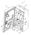
本発明が適用されたスロットマシンの実施例について図面を用いて説明すると、本実施例のスロットマシン1は、図2に示すように、前面が開口する筐体1aと、この筐体1aの側端に回動自在に枢支された前面扉1bと、から構成されている。
An embodiment of a slot machine to which the present invention is applied will be described with reference to the drawings. As shown in FIG. 2, a
本実施例のスロットマシン1の筐体1aの内部には、図2に示すように、外周に複数種の図柄が配列されたリール2L、2C、2R(以下、左リール、中リール、右リール)が平方向に並設されており、図1に示すように、これらリール2L、2C、2Rに配列された図柄のうち連続する3つの図柄が前面扉1bに設けられた透視窓3から見えるように配置されている。
Inside the
リール2L、2C、2Rの外周部には、図3に示すように、それぞれ「7a」、「7b」、「7c」、「スイカa」、「スイカb」、「チェリー」、「ベルa」、「ベルb」、「リプレイa」、「リプレイb」といった互いに識別可能な複数種類の図柄が所定の順序で、それぞれ21個ずつ描かれている。リール2L、2C、2Rの外周部に描かれた図柄は、前面扉1bのリールパネル1c略中央に設けられた透視窓3において各々上中下三段に表示される。尚、以下では、「7a」、「7b」、「7c」をまとめて単に「7」、「スイカa」、「スイカb」をまとめて単に「スイカ」、「ベルa」、「ベルb」をまとめて単に「ベル」、「リプレイa」、「リプレイb」をまとめて単に「リプレイ」と呼ぶ場合がある。
As shown in FIG. 3, "7a", "7b", "7c", "watermelon a", "watermelon b", "cherry", "bell a" are provided on the outer periphery of the
各リール2L、2C、2Rは、各々対応して設けられリールモータ32L、32C、32R(図4参照)によって回転させることで、各リール2L、2C、2Rの図柄が透視窓3に連続的に変化しつつ表示されるとともに、各リール2L、2C、2Rの回転を停止させることで、透視窓3に3つの連続する図柄が表示結果として導出表示されるようになっている。
The
リール2L、2C、2Rの内側には、リール2L、2C、2Rそれぞれに対して、基準位置を検出するリールセンサ33L、33C、33Rと、リール2L、2C、2Rを背面から照射するリールLED55と、が設けられている。また、リールLED55は、リール2L、2C、2Rの連続する3つの図柄に対応する12のLEDからなり、各図柄をそれぞれ独立して照射可能とされている。
Inside the
前面扉1bにおいて各リール2L、2C、2Rに対応する位置には、リール2L、2C、2Rを前面側から透視可能とする横長長方形状の透視窓3が設けられており、該透視窓3を介して遊技者側から各リール2L、2C、2Rが視認できるようになっている。
In the
前面扉1bには、図1に示すように、メダルを投入可能なメダル投入部4、メダルが払い出されるメダル払出口9、クレジット(遊技者所有の遊技用価値として記憶されているメダル数)を用いて、その範囲内において遊技状態に応じて定められた規定数の賭数のうち最大の賭数(本実施例ではいずれの遊技状態においても3)を設定する際に操作されるMAXBETスイッチ6、クレジットとして記憶されているメダル及び賭数の設定に用いたメダルを精算する(クレジット及び賭数の設定に用いた分のメダルを返却させる)際に操作される精算スイッチ10、ゲームを開始する際に操作されるスタートスイッチ7、リール2L、2C、2Rの回転を各々停止する際に操作されるストップスイッチ8L、8C、8R、演出に用いるための演出用スイッチ56が遊技者により操作可能にそれぞれ設けられている。
As shown in FIG. 1, on the
尚、本実施例では、回転を開始した3つのリール2L、2C、2Rのうち、最初に停止するリールを第1停止リールと称し、また、その停止を第1停止と称する。同様に、2番目に停止するリールを第2停止リールと称し、また、その停止を第2停止と称し、3番目に停止するリールを第3停止リールと称し、また、その停止を第3停止あるいは最終停止と称する。
In this embodiment, among the three
また、前面扉1bには、図1に示すように、クレジットとして記憶されているメダル枚数が表示されるクレジット表示器11、入賞の発生により払い出されたメダル枚数やエラー発生時にその内容を示すエラーコード等が表示される遊技補助表示器12、賭数が1設定されている旨を点灯により報知する1BETLED14、賭数が2設定されている旨を点灯により報知する2BETLED15、賭数が3設定されている旨を点灯により報知する3BETLED16、メダルの投入が可能な状態を点灯により報知する投入要求LED17、スタートスイッチ7の操作によるゲームのスタート操作が有効である旨を点灯により報知するスタート有効LED18、ウェイト(前回のゲーム開始から一定期間経過していないためにリールの回転開始を待機している状態)中である旨を点灯により報知するウェイト中LED19、後述するリプレイゲーム中である旨を点灯により報知するリプレイ中LED20が設けられた遊技用表示部13が設けられている。
Further, as shown in FIG. 1, the
MAXBETスイッチ6の内部には、MAXBETスイッチ6の操作による賭数の設定操作が有効である旨を点灯により報知するBETスイッチ有効LED21(図4参照)が設けられており、ストップスイッチ8L、8C、8Rの内部には、該当するストップスイッチ8L、8C、8Rによるリールの停止操作が有効である旨を点灯により報知する左、中、右停止有効LED22L、22C、22R(図4参照)がそれぞれ設けられている。
Inside the
また、前面扉1bにおけるストップスイッチ8L、8C、8Rの下方には、スロットマシン1のタイトルや配当表などが印刷された下部パネルが設けられている。
Further, below the stop switches 8L, 8C, and 8R on the
また、前面扉1bの透視窓3の上方には、液晶表示器51や演出効果LED52が設けられている。さらに、メダル払い出し口9の両側方には、スピーカ53,54が設けられている。液晶表示器51からは演出の実行時に演出画像が表示され、デモ状態への移行時にでも画像が表示される。また、演出効果LED52は常時点灯しており、演出の実行時には演出に合わせた点灯パターンで点灯する。スピーカ53,54からはリールの回転音やストップスイッチの操作音、演出音などが再生される。演出状態がAT(アシストタイム)に制御されたとき(ART(アシストリプレイタイム)に制御されたときを含む)には、液晶表示器51からはストップスイッチ8L,8C,8Rの操作順序を示す画像が表示され、演出効果LED52はストップスイッチ8L,8C,8Rの操作順序に合わせて点灯し、スピーカ53,54からはストップスイッチ8L,8C,8Rの操作順序を示す音声が再生される。演出効果LED52は前面扉1bに向かって中央、左方、右方の3ブロックに分けて設置されている。そして、ATに制御されたときは、ストップスイッチ8Lを操作することを促すナビ演出を実行するときは左方の演出効果LED52、ストップスイッチ8Cを操作することを促すナビ演出を実行するときは中央の演出効果LED52、ストップスイッチ8Rを操作することを促すナビ演出を実行するときは右方の演出効果LED52が点灯する。
Further, a
前面扉1bの内側には、後述する設定値の変更中や設定値の確認中にその時点の設定値が表示される設定値表示器24、後述のRT3終了時に打止状態(リセット操作がなされるまでゲームの進行が規制される状態)に制御する打止機能の有効/無効を選択するための打止スイッチ36a、後述のRT3終了時に自動精算処理(クレジットとして記憶されているメダルを遊技者の操作によらず精算(返却)する処理)に制御する自動精算機能の有効/無効を選択するための自動精算スイッチ36b、メダル投入部4から投入されたメダルの流路を、筐体1a内部に設けられた後述のホッパータンク34a(図2参照)側、または前面扉1bのメダル払出口9側のいずれか一方に選択的に切り替えるための流路切替ソレノイド30(図4参照)、メダル投入部4から投入されてホッパータンク34a側に流下したメダルを検出する投入メダルセンサ31(図4参照)を有するメダルセレクタ29、前面扉1bの開放状態を検出するドア開放検出スイッチ25(図4参照)が設けられている。
Inside the
筐体1a内部には、図2に示すように、リール2L、2C、2R、リールモータ32L、32C、32R(図4参照)、各リール2L、2C、2Rのリール基準位置をそれぞれ検出可能なリールセンサ33L、33C、33R(図4参照)からなるリールユニット2、外部出力信号を出力するための外部出力基板1000(図4参照)、メダル投入部4から投入されたメダルを貯留するホッパータンク34a、ホッパータンク34aに貯留されたメダルをメダル払出口9より払い出すためのホッパーモータ34b(図4参照)、ホッパーモータ34bの駆動により払い出されたメダルを検出する払出センサ34c(図4参照)からなるホッパーユニット34、電源ボックス100が設けられている。
As shown in FIG. 2, the
ホッパーユニット34の側部には、ホッパータンク34aから溢れたメダルが貯留されるオーバーフロータンク35が設けられている。オーバーフロータンク35の内部には、貯留された所定量のメダルを検出可能な高さに設けられた左右に離間する一対の導電部材からなる満タンセンサ35a(図4参照)が設けられており、導電部材がオーバーフロータンク35内に貯留されたメダルを介して接触することにより導電したときに内部に貯留されたメダル貯留量が所定量以上となったこと、すなわちオーバーフロータンクが満タン状態となったことを検出できるようになっている。
On the side of the
電源ボックス100の前面には、図2に示すように、設定変更状態または設定確認状態に切り替えるための設定キースイッチ37、通常時においてはエラー状態や打止状態を解除するためのリセットスイッチとして機能し、設定変更状態においては後述する内部抽選の当選確率(出玉率)の設定値を変更するための設定スイッチとして機能するリセット/設定スイッチ38、電源をON/OFFする際に操作される電源スイッチ39が設けられている。
As shown in FIG. 2, a
これら筐体1aの内部にある打止スイッチ36a、自動精算スイッチ36b、設定キースイッチ37、リセット/設定スイッチ38、電源スイッチ39は、遊技場の店員によるキー操作により前面扉1bを開放しなければ操作できないことから、遊技場に設置されている場合に、遊技場の店員のみが操作可能とされ、遊技者が操作することはできないようになっている。また、リセット/設定スイッチ38も同様である。特に、設定キースイッチ37は、キー操作により前面扉1bを開放したうえで、さらにキー操作を要することから、遊技場の店員のなかでも、設定キースイッチ37の操作を行うキーを所持する店員のみ操作が可能とされている。
The
また、図2に示すように、リセット/設定スイッチ38及び電源スイッチ39が前面に設けられた電源ボックス100の前面を被覆可能な前面カバー100aが設けられている。前面カバー100aは電源ボックス100の一端に開閉可能に枢支されており、前面カバー100aを開放しない限り、リセット/設定スイッチ38及び電源スイッチ39を操作できないようになっている。
Further, as shown in FIG. 2, a
本実施例のスロットマシン1においてゲームを行う場合には、まず、メダルをメダル投入部4から投入するか、あるいはクレジットを使用して賭数を設定する。クレジットを使用するにはMAXBETスイッチ6を操作すれば良い。遊技状態に応じて定められた規定数の賭数が設定されると、入賞ラインLN(図1参照)が有効となり、スタートスイッチ7の操作が有効な状態、すなわち、ゲームが開始可能な状態となる。本実施例では、規定数の賭数として遊技状態に関わらず3枚が定められて、規定数の賭数が設定されると入賞ラインLNが有効となる。尚、遊技状態に対応する規定数のうち最大数を超えてメダルが投入された場合には、その分はクレジットに加算される。
When a game is played in the
入賞ラインとは、各リール2L、2C、2Rの透視窓3に表示された図柄の組み合わせが入賞図柄の組み合わせであるかを判定するために設定されるラインである。本実施例では、図1に示すように、リール2Lの中段、リール2Cの中段、リール2Rの中段、すなわち中段に水平方向に並んだ図柄に跨って設定された入賞ラインLNのみが入賞ラインとして定められている。尚、本実施例では、1本の入賞ラインのみを適用しているが、複数の入賞ラインを適用しても良い。
The winning line is a line that is set to determine whether a combination of symbols displayed on the
また、本実施例では、入賞ラインLNに入賞を構成する図柄の組み合わせが、揃ったことを認識しやすくするために、入賞ラインLNとは別に、無効ラインLM1〜4を設定している。無効ラインLM1〜4は、これら無効ラインLM1〜4に揃った図柄の組み合わせによって入賞が判定されるものではなく、入賞ラインLNに特定の入賞を構成する図柄の組み合わせが揃った際に、無効ラインLM1〜4のいずれかに入賞ラインLNに揃った場合に入賞となる図柄の組み合わせ(例えば、ベル−ベル−ベル)が揃う構成とすることで、入賞ラインLNに特定の入賞を構成する図柄の組み合わせが揃ったことを認識しやすくするものである。本実施例では、図1に示すように、リール2Lの上段、リール2Cの上段、リール2Rの上段、すなわち上段に水平方向に並んだ図柄に跨って設定された無効ラインLM1、リール2Lの下段、リール2Cの下段、リール2Rの下段、すなわち下段に水平方向に並んだ図柄に跨って設定された無効ラインLM2、リール2Lの上段、リール2Cの中段、リール2Rの下段、すなわち右下がりに並んだ図柄に跨って設定された無効ラインLM3、リール2Lの下段、リール2Cの中段、リール2Rの上段、すなわち右上がりに並んだ図柄に跨って設定された無効ラインLM4の4種類が無効ラインLMとして定められている。
In the present embodiment, invalid lines LM1 to LM1-4 are set apart from the winning line LN in order to make it easy to recognize that the combination of symbols constituting the winning line is aligned on the winning line LN. The invalid lines LM1 to LM4 are not determined based on the combination of symbols aligned with the invalid lines LM1 to LM4. When the combination of symbols constituting a specific prize is arranged on the winning line LN, the invalid line LM1 to LM4. When a combination of symbols (for example, bell-bell-bell) is awarded when the winning line LN is aligned with any of the LM1 to LM4, the symbols constituting the particular winning line LN It is easy to recognize that the combination is complete. In this embodiment, as shown in FIG. 1, an invalid line LM1 and a lower stage of the
ゲームが開始可能な状態でスタートスイッチ7を操作すると、各リール2L、2C、2Rが回転し、各リール2L、2C、2Rの図柄が連続的に変動する。この状態でいずれかのストップスイッチ8L、8C、8Rを操作すると、対応するリール2L、2C、2Rの回転が停止し、透視窓3に表示結果が導出表示される。
When the
そして、全てのリール2L、2C、2Rが停止されることで1ゲームが終了し、入賞ラインLN上に予め定められた図柄の組み合わせ(以下、役とも呼ぶ)が各リール2L、2C、2Rの表示結果として停止した場合には入賞が発生し、その入賞に応じて定められた枚数のメダルが遊技者に対して付与されてクレジットに加算される。クレジットが上限数(本実施例では50)に達した場合には、メダルがメダル払出口9(図1参照)から直接払い出される。また、入賞ラインLN上に、遊技状態の移行を伴う図柄の組み合わせが各リール2L、2C、2Rの表示結果として停止した場合には、図柄の組み合わせに応じた
遊技状態に移行する。
Then, when all the
尚、本実施例では、3つのリール2L、2C、2Rを用いた構成を例示しているが、リールを1つのみ用いた構成、2つのリールを用いた構成、4つ以上のリールを用いた構成としても良く、2つ以上のリールを用いた構成においては、2つ以上の全てのリールに導出された表示結果の組み合わせに基づいて入賞を判定する構成とすれば良い。
In this embodiment, a configuration using three
また、本実施例におけるスロットマシン1にあっては、ゲームが開始されて各リール2L、2C、2Rが回転して図柄の変動が開始した後、いずれかのストップスイッチ8L、8C、8Rが操作されたときに、当該ストップスイッチ8L、8C、8Rに対応するリールの回転が停止して図柄が停止表示される。また、ストップスイッチ8L、8C、8Rの操作から対応するリール2L、2C、2Rの回転を停止するまでの最大停止遅延時間は190ms(ミリ秒)である。
In the
リール2L、2C、2Rは、1分間に80回転されることで、80×21(1リール当たりの図柄コマ数)=1680コマ分の図柄を変動させるので、190ms間では最大で4コマの図柄を引き込むことができることとなる。つまり、停止図柄として選択可能なのは、ストップスイッチ8L、8C、8Rが操作されたときに表示されている図柄と、そこから4コマ先までにある図柄、合計5コマ分の図柄である。
The
このため、例えば、ストップスイッチ8L、8C、8Rのいずれかが操作されたときに当該ストップスイッチに対応するリールの下段に表示されている図柄を基準とした場合、当該図柄から4コマ先までの図柄を下段に表示させることができるため、リール2L、2C、2R各々において、ストップスイッチ8L、8Rのうちいずれかが操作されたときに、当該ストップスイッチに対応するリールの中段に表示されている図柄を含めて5コマ以内に配置されている図柄を、入賞ライン上に表示させることができる。
For this reason, for example, when any one of the stop switches 8L, 8C, 8R is operated and the symbol displayed on the lower stage of the reel corresponding to the stop switch is used as a reference, the symbol from the symbol to four frames ahead is used. Since the symbol can be displayed in the lower row, when one of the stop switches 8L, 8R is operated in each of the
図4は、スロットマシン1の構成を示すブロック図である。スロットマシン1には、図4に示すように、遊技制御基板40、第1演出制御基板90、第2演出制御基板190、電源基板101が設けられており、遊技制御基板40によって遊技状態が制御され、第1演出制御基板90及び第2演出制御基板190によって遊技状態に応じた演出が制御され、電源基板101によってスロットマシン1を構成する電気部品の駆動電源が生成され、各部に供給される。
FIG. 4 is a block diagram showing a configuration of the
電源基板101には、外部からAC100Vの電源が供給されるとともに、このAC100Vの電源からスロットマシン1を構成する電気部品の駆動に必要な直流電圧が生成され、遊技制御基板40及び遊技制御基板40を介して接続された第1演出制御基板90に供給され、さらに第1演出制御基板90を介して第2演出制御基板190に供給されるようになっている。尚、第1演出制御基板90に対して電源を供給する電源供給ラインが遊技制御基板40を介さず、電源基板101から第1演出制御基板90に直接接続され、電源基板101から第1演出制御基板90に対して直接電源が供給される構成としても良い。また、第2演出制御基板190に対して電源を供給する電源供給ラインが第1演出制御基板90を介さず、電源基板101または遊技制御基板40から第2演出制御基板190に直接接続され、電源基板101または遊技制御基板40から第2演出制御基板190に対して直悦電源が供給される構成としても良い。
The
また、電源基板101には、前述したホッパーモータ34b、払出センサ34c、満タンセンサ35a、設定キースイッチ37、リセット/設定スイッチ38、電源スイッチ39が接続されている。
Further, the above-described
遊技制御基板40には、前述した1枚BETスイッチ5、MAXBETスイッチ6、スタートスイッチ7、ストップスイッチ8L、8C、8R、精算スイッチ10、リセット/設定スイッチ38、打止スイッチ36a、自動精算スイッチ36b、投入メダルセンサ31、ドア開放検出スイッチ25、リールセンサ33L、33C、33Rが接続されているとともに、電源基板101を介して前述した払出センサ34c、満タンセンサ35a、設定キースイッチ37、リセット/設定スイッチ38が接続されており、これらに接続されたスイッチ類の検出信号が入力されるようになっている。
On the
また、遊技制御基板40には、前述したクレジット表示器11、遊技補助表示器12、1〜3BETLED14〜16、投入要求LED17、スタート有効LED18、ウェイト中LED19、リプレイ中LED20、BETスイッチ有効LED21、左、中、右停止有効LED22L、22C、22R、設定値表示器24、流路切替ソレノイド30、リールモータ32L、32C、32Rが接続されているとともに、電源基板101を介して前述したホッパーモータ34bが接続されており、これら電気部品は、遊技制御基板40に搭載された後述のメイン制御部41の制御に基づいて駆動されるようになっている。
Further, the
遊技制御基板40には、メイン制御部41、制御用クロック生成回路42、乱数用クロック生成回路43、スイッチ検出回路44、モータ駆動回路45、ソレノイド駆動回路46、LED駆動回路47、電断検出回路48、リセット回路49が搭載されている。
The
メイン制御部41は、遊技の進行に関する処理を行うととともに、遊技制御基板40に搭載された制御回路の各部を直接的または間接的に制御する。
The
制御用クロック生成回路42は、メイン制御部41の外部にて、所定周波数の発振信号となる制御用クロックCCLKを生成する。制御用クロック生成回路42により生成された制御用クロックCCLKは、図5に示すクロック回路502に供給される。乱数用クロック生成回路43は、メイン制御部41の外部にて、制御用クロックCCLKの発振周波数とは異なる所定周波数の発振信号となる乱数用クロックRCLKを生成する。乱数用クロック生成回路43により生成された乱数用クロックRCLKは、図5に示す乱数回路508a、508bに供給される。
The control
スイッチ検出回路44は、遊技制御基板40に直接または電源基板101を介して接続されたスイッチ類から入力された検出信号を取り込んでメイン制御部41に伝送する。モータ駆動回路45は、メイン制御部41から出力されたモータ駆動信号(ステッピングモータの位相信号)をリールモータ32L、32C、32Rに伝送する。ソレノイド駆動回路46は、メイン制御部41から出力されたソレノイド駆動信号を流路切替ソレノイド30に伝送する。LED駆動回路47は、メイン制御部41から出力されたLED駆動信号を遊技制御基板40に接続された各種表示器やLEDに伝送する。電断検出回路48は、スロットマシン1に供給される電源電圧を監視し、電圧低下を検出したときに、その旨を示す電圧低下信号をメイン制御部41に対して出力する。リセット回路49は、電源投入時または電源遮断時などの電源が不安定な状態においてメイン制御部41にシステムリセット信号を与える。
The
図5は、遊技制御基板40に搭載されたメイン制御部41の構成例を示している。図5に示すメイン制御部41は、1チップマイクロコンピュータであり、外部バスインタフェース501と、クロック回路502と、照合用ブロック503と、固有情報記憶回路504と、演算回路505と、リセット/割込コントローラ506と、CPU(Central Processing Unit)41aと、ROM(Read ONly Memory)41bと、RAM(Random Access Memory)41cと、フリーランカウンタ回路507と、乱数回路508a、508bと、タイマ回路509と、割込コントローラ510と、パラレル入力ポート511と、シリアル通信回路512と、パラレル出力ポート513と、アドレスデコード回路514と、を備えて構成される。
FIG. 5 shows a configuration example of the
リセット/割込コントローラ506は、メイン制御部41の内部や外部にて発生する各種リセット、割込み要求を制御するためのものである。
The reset / interrupt
リセット/割込コントローラ506は、指定エリア外走行禁止(IAT)回路506aとウォッチドッグタイマ(WDT)506bとを備える。IAT回路506aは、ユーザプログラムが指定エリア内で正しく実行されているか否かを監視する回路であり、指定エリア外でユーザプログラムが実行されたことを検出するとIAT発生信号を出力する機能を備える。また、ウォッチドッグタイマ506bは、設定期間ごとにタイムアウト信号を発生させる機能を備える。
The reset / interrupt
外部バスインタフェース501は、メイン制御部41を構成するチップの外部バスと内部バスとのインタフェース機能や、アドレスバス、データバス及び各制御信号の方向制御機能などを有するバスインタフェースである。
The
クロック回路502は、制御用クロックCCLKを2分周することなどにより、内部システムクロックSCLKを生成する回路である。
The
照合用ブロック503は、外部の照合機と接続し、チップの照合を行う機能を備える。固有情報記憶回路504は、メイン制御部41の内部情報となる複数種類の固有情報を記憶する回路である。演算回路505は、乗算及び除算を行う回路である。
The
CPU41aは、ROM41bから読み出した制御コードに基づいてユーザプログラム(ゲーム制御用の遊技制御処理プログラム)を実行することにより、スロットマシン1における遊技制御を実行する制御用CPUである。こうした遊技制御が実行されるときには、CPU41aがROM41bから固定データを読み出す固定データ読出動作や、CPU41aがRAM41cに各種の変動データを書き込んで一時記憶させる変動データ書込動作、CPU41aがRAM41cに一時記憶されている各種の変動データを読み出す変動データ読出動作、CPU41aが外部バスインタフェース501やパラレル入力ポート511、シリアル通信回路512などを介してメイン制御部41の外部から各種信号の入力を受け付ける受信動作、CPU41aが外部バスインタフェース501やシリアル通信回路512、パラレル出力ポート513などを介してメイン制御部41の外部へと各種信号を出力する送信動作等も行われる。
The
ROM41bには、ユーザプログラム(ゲーム制御用の遊技制御処理プログラム)を示す制御コードや固定データ等が記憶されている。
The
RAM41cは、ゲーム制御用のワークエリアを提供する。ここで、RAM41cの少なくとも一部は、バックアップ電源によってバックアップされているバックアップRAMであれば良い。すなわち、スロットマシン1への電力供給が停止しても、所定期間はRAM41cの少なくとも一部の内容が保存される。
The
フリーランカウンタ回路507として、8ビットのフリーランカウンタを4チャネル搭載している。
As the free-
乱数回路508a、508bは、8ビット乱数や16ビット乱数といった、所定の更新範囲を有する乱数値となる数値データを生成する回路である。本実施例では、乱数回路508a、508bのうち16ビット乱数回路508bが生成するハードウェア乱数は、後述する内部抽選用の乱数として用いられる。
The
タイマ回路509は、8ビットプログラマブルタイマであり、メイン制御部41は、タイマ回路509として、8ビットのカウンタを3チャネル備える。本実施例では、タイマ回路509を用いてユーザプログラムによる設定により、リアルタイム割込要求や時間計測を行うことが可能である。
The
割込コントローラ510は、PI5/XINT端子からの外部割込要求や、内蔵の周辺回路(例えば、シリアル通信回路512、乱数回路508a、508b、タイマ回路509)からの割込要求を制御する回路である。
The interrupt
パラレル入力ポート511は、8ビット幅の入力専用ポート(PIP)を内蔵する。また、図5に示すメイン制御部41が備えるパラレル出力ポート513は、11ビット幅の出力専用ポート(POP)を内蔵する。
The
シリアル通信回路512は、外部に対する入出力において非同期シリアル通信を行う回路である。尚、メイン制御部41は、シリアル通信回路512として、送受信両用の1チャネルの回路と、送信用のみの3チャネルの回路と、を備える。
The
アドレスデコード回路514は、メイン制御部41の内部における各機能ブロックのデコードや、外部装置用のデコード信号であるチップセレクト信号のデコードを行うための回路である。チップセレクト信号により、メイン制御部41の内部回路、或いは、周辺デバイスとなる外部装置を、選択的に有効動作させて、CPU41aからのアクセスが可能となる。
The
本実施例においてメイン制御部41は、シリアル通信回路512を介して第1サブ制御部91に各種のコマンドを送信する。メイン制御部41から第1サブ制御部91へ送信されるコマンドは一方向のみで送られ、第1サブ制御部91からメイン制御部41へ向けてコマンドが送られることはない。また、本実施例では、シリアル通信回路512を介して第1サブ制御部91に対してコマンドを送信する構成、すなわちコマンドをシリアル信号にて送信する構成であるが、パラレル出力ポート513を介して第1サブ制御部91に対してコマンドが送信される構成、すなわちコマンドがパラレル信号にて送信される構成としても良い。
In this embodiment, the
また、メイン制御部41は、遊技制御基板40に接続された各種スイッチ類の検出状態をパラレル入力ポート511から入力する。そしてメイン制御部41は、これらパラレル入力ポート511から入力される各種スイッチ類の検出状態に応じて段階的に移行する基本処理を実行する。
Further, the
また、メイン制御部41は、割込の発生により基本処理に割り込んで割込処理を実行できるようになっている。本実施例では、タイマ回路509にてタイムアウトが発生したこと、すなわち一定時間間隔(本実施例では、約0.56ms)毎に後述するタイマ割込処理(メイン)を実行する。
Further, the
また、メイン制御部41は、割込処理の実行中に他の割込を禁止するように設定されているとともに、複数の割込が同時に発生した場合には、予め定められた順位によって優先して実行する割込が設定されている。尚、割込処理の実行中に他の割込要因が発生し、割込処理が終了してもその割込要因が継続している状態であれば、その時点で新たな割込が発生することとなる。
The
メイン制御部41は、基本処理として遊技制御基板40に接続された各種スイッチ類の検出状態が変化するまでは制御状態に応じた処理を繰り返しループし、各種スイッチ類の検出状態の変化に応じて段階的に移行する処理を実行する。また、メイン制御部41は、一定時間間隔(本実施例では、約0.56ms)毎にタイマ割込処理(メイン)を実行する。尚、タイマ割込処理(メイン)の実行間隔は、基本処理において制御状態に応じて繰り返す処理が一巡する時間とタイマ割込処理(メイン)の実行時間とを合わせた時間よりも長い時間に設定されており、今回と次回のタイマ割込処理(メイン)との間で必ず制御状態に応じて繰り返す処理が最低でも一巡することとなる。
The
第1演出制御基板90には、演出用スイッチ56が接続されており、この演出用スイッチ56の検出信号が入力されるようになっている。
An
第1演出制御基板90には、第1サブCPU91a、ROM91b、RAM91c、I/Oポート91dを備えたマイクロコンピュータにて構成され、演出の制御を行う第1サブ制御部91、電源投入時または第1サブCPU91aからの初期化命令が一定時間入力されないときに第1サブCPU91aにリセット信号を与えるリセット回路95、第1演出制御基板90に接続された演出用スイッチ56から入力された検出信号を検出するスイッチ検出回路96、日付情報及び時刻情報を含む時間情報を出力する時計装置97、スロットマシン1に供給される電源電圧を監視し、電圧低下を検出したときに、その旨を示す電圧低下信号を第1サブCPU91aに対して出力する電断検出回路98、その他の回路等、が搭載されており、第1サブCPU91aは、遊技制御基板40から送信されるコマンドを受けて、演出を行うための各種の制御を行う。
The first
リセット回路95は、遊技制御基板40においてメイン制御部41にシステムリセット信号を与えるリセット回路49よりもリセット信号を解除する電圧が低く定められており、電源投入時において第1サブ制御部91は、メイン制御部41よりも早い段階で起動するようになっている。一方で、電断検出回路98は、遊技制御基板40においてメイン制御部41に電圧低下信号を出力する電断検出回路48よりも電圧低下信号を出力する電圧が低く定められており、電断時において第1サブ制御部91は、メイン制御部41よりも遅い段階で停電を検知し、後述する電断処理(サブ)を行うこととなる。
The
第1サブ制御部91は、メイン制御部41と同様に、割込機能を備えており、メイン制御部41からのコマンド受信時に割込を発生させて、メイン制御部41から送信されたコマンドを取得し、バッファに格納するコマンド受信割込処理を実行する。また、第1サブ制御部91は、システムクロックの入力数が一定数に到達する毎、すなわち一定時間間隔(約2ms)毎に割込を発生させて後述するタイマ割込処理(サブ)を実行する。
Similar to the
また、第1サブ制御部91は、メイン制御部41とは異なり、コマンドの受信に基づいて割込が発生した場合には、タイマ割込処理(サブ)の実行中であっても、当該処理に割り込んでコマンド受信割込処理を実行し、タイマ割込処理(サブ)の契機となる割込が同時に発生してもコマンド受信割込処理を最優先で実行するようになっている。
Also, unlike the
また、第1サブ制御部91にも、停電時においてバックアップ電源が供給されており、バックアップ電源が供給されている間は、RAM91cに記憶されているデータが保持されるようになっている。
The first
本実施例において第1サブ制御部91は、シリアル通信回路(図示略)を介して第2サブ制御部191に演出装置の出力パターンを示す各種の出力制御コマンドを送信する。第1サブ制御部91から第2サブ制御部191へ送信される出力制御コマンドは一方向のみで送られ、第2サブ制御部191から第1サブ制御部91へ向けて出力制御コマンドが送られることはない。また、本実施例では、シリアル通信回路を介して第2サブ制御部191に対して出力制御コマンドを送信する構成、すなわち出力制御コマンドをシリアル信号にて送信する構成であるが、パラレル出力ポート(図示略)を介して第2サブ制御部191に対して出力制御コマンドが送信される構成、すなわち出力制御コマンドがパラレル信号にて送信される構成としても良い。
In the present embodiment, the first
また、本実施例では、第1サブ制御部91から第2サブ制御部191へ送信される出力制御コマンドは一方向のみで送られる構成であるが、第2サブ制御部191から第1サブ制御部91へ第2サブ制御部191の制御状態を示すコマンドを送信する構成、すなわち第1サブ制御部91と第2サブ制御部191とが双方向通信可能な構成としても良い。この場合には、例えば、各演出装置の出力状況を監視し、演出装置に異常等が生じた際に、演出装置の異常等を第1サブ制御部91に通知するようにしても良い。また、タッチセンサ付液晶表示装置や演出用スイッチといった入力機器を接続し、入力機器からの入力情報を特定可能なコマンドを第2サブ制御部191が第1サブ制御部91に送信するようにしても良い。
In this embodiment, the output control command transmitted from the first
第2演出制御基板190には、スロットマシン1の前面扉1bに配置された液晶表示器51(図1参照)、演出効果LED52、演出用停止LED57a、57b、スピーカ53、54、前述したリールLED55等の演出装置が接続されており、これら演出装置は、第2演出制御基板190に搭載された第2サブ制御部191による制御に基づいて駆動されるようになっている。
The second
尚、本実施例では、演出装置として液晶表示器51、演出効果LED52、演出用停止LED57a、57b、スピーカ53、54、リールLED55を例示しているが、演出装置は、これらに限られず、例えば、機械的に駆動する表示装置や機械的に駆動する役モノなどを演出装置として適用しても良い。
In this embodiment, the
第2演出制御基板190には、第2サブCPU191a、ROM191b、RAM191c、I/Oポート191dを備えたマイクロコンピュータにて構成され、演出装置の出力制御を行う第2サブ制御部191、第2演出制御基板190に接続された液晶表示器51の表示制御を行う表示制御回路92、演出効果LED52、リールLED55の駆動制御を行うLED駆動回路93、スピーカ53、54からの音声出力制御を行う音声出力回路94、電源投入時または第2サブCPU191aからの初期化命令が一定時間入力されないときに第2サブCPU191aにリセット信号を与えるリセット回路195、各演出装置に実行させる演出に用いるデータ(例えば、液晶表示器51にて表示される画像データ、スピーカ53、54から出力される音声データ等)が予め記録された演出データ用ROM、その他の回路等、が搭載されており、第2サブ制御部191は、第1サブ制御部91から送信される出力制御コマンドに基づいて各種の演出装置の出力制御を直接的または間接的に行えるようになっている。
The second
尚、第2サブ制御部191には、第1サブ制御部91と異なり停電時においてバックアップ電源は供給されず、停電時にはRAM191cに記憶されているデータは保持されないようになっている。
Note that unlike the first
本実施例では、演出に関する制御が、第1演出制御基板90に搭載された第1サブ制御部91と、第2演出制御基板190に搭載された第2サブ制御部191と、により連携して行われる。
In the present embodiment, the production control is coordinated by the first
詳しくは、第1サブ制御部91は、メイン制御部41から送信されたコマンドに基づいて演出パターン、遊技者にとっての有利度に影響する後述のARTに関する制御、演出装置の制御パターンを決定し、決定結果に基づいて演出装置の出力パターンを特定可能な出力制御コマンドを第2サブ制御部191に対して送信する。
Specifically, the first
一方、第2サブ制御部191は、第1サブ制御部91から送信された出力制御パターンから演出装置の出力パターンを特定し、特定した出力パターンに基づいて演出装置の出力制御を行うようになっている。
On the other hand, the second
すなわち本実施例では、第1サブ制御部91が、演出内容(遊技者にとっての有利度に影響する演出を含む)を決定する一方、第2サブ制御部191が、第1サブ制御部91による決定内容に従って演出装置の出力制御のみを行うようになっており、第2サブ制御部191は、独自に演出内容を決定しない構成となっている。
That is, in the present embodiment, the first
本実施例のスロットマシン1は、設定値に応じてメダルの払出率が変わるものである。詳しくは、後述する内部抽選、ナビストック抽選等において設定値に応じた当選確率を用いることにより、メダルの払出率が変わるようになっている。設定値は1〜6の6段階からなり、6が最も払出率が高く、5、4、3、2、1の順に値が小さくなるほど払出率が低くなる。すなわち設定値として6が設定されている場合には、遊技者にとって最も有利度が高く、5、4、3、2、1の順に値が小さくなるほど有利度が段階的に低くなる。
In the
設定値を変更するためには、設定キースイッチ37をON状態としてからスロットマシン1の電源をONする必要がある。設定キースイッチ37をON状態として電源をONすると、設定値表示器24にRAM41cから読み出された設定値が表示値として表示され、リセット/設定スイッチ38の操作による設定値の変更操作が可能な設定変更状態に移行する。設定変更状態において、リセット/設定スイッチ38が操作されると、設定値表示器24に表示された表示値が1ずつ更新されていく(設定値6からさらに操作されたときは、設定値1に戻る)。そして、スタートスイッチ7が操作されると表示値を設定値として確定する。そして、設定キースイッチ37がOFFされると、確定した表示値(設定値)がメイン制御部41のRAM41cに格納され、遊技の進行が可能な状態に移行する。
In order to change the setting value, it is necessary to turn on the power of the
また、設定値を確認するためには、ゲーム終了後、賭数が設定されていない状態で設定キースイッチ37をON状態とすれば良い。このような状況で設定キースイッチ37をON状態とすると、設定値表示器24にRAM41cから読み出された設定値が表示されることで設定値を確認可能な設定確認状態に移行する。設定確認状態においては、ゲームの進行が不能であり、設定キースイッチ37をOFF状態とすることで、設定確認状態が終了し、ゲームの進行が可能な状態に復帰することとなる。
In order to confirm the set value, after the game is over, the setting
本実施例のスロットマシン1においては、メイン制御部41は、タイマ割込処理(メイン)を実行する毎に、電断検出回路48からの電圧低下信号が検出されているか否かを判定する停電判定処理を行い、停電判定処理において電圧低下信号が検出されていると判定した場合に、次回復帰時にRAM41cのデータが正常か否かを判定するためのデータを設定する電断処理(メイン)を実行する。
In the
そして、メイン制御部41は、その起動時においてRAM41cのデータが正常であることを条件に、RAM41cに記憶されているデータに基づいてメイン制御部41の処理状態を電断前の状態に復帰させるが、RAM41cデータが正常でない場合には、RAM異常と判定し、RAM異常エラーコードをレジスタにセットしてRAM異常エラー状態に制御し、遊技の進行を不能化させるようになっている。
Then, the
また、第1サブ制御部91もタイマ割込処理(サブ)において電断検出回路98からの電圧低下信号が検出されているか否かを判定し、電圧低下信号が検出されていると判定した場合に、次回復帰時にRAM91cのデータが正常か否かを判定するためのデータを設定する電断処理(サブ)を実行する。
Further, the first
そして、第1サブ制御部91は、その起動時においてRAM91cのデータが正常であることを条件に、RAM91cに記憶されているデータに基づいて第1サブ制御部91の処理状態を電断前の状態に復帰させるが、RAM91cのデータが正常でない場合には、RAM異常と判定し、RAM91cを初期化するようになっている。この場合、メイン制御部41と異なり、RAM91cが初期化されるのみで演出の実行が不能化されることはない。
Then, the first
また、第1サブ制御部91は、その起動時においてRAM91cのデータが正常であると判断された場合でも、メイン制御部41から設定変更状態に移行した旨を示す後述の設定コマンドを受信した場合、起動後一定時間が経過してもメイン制御部41の制御状態が復帰した旨を示す後述の復帰コマンドも設定コマンドも受信しない場合にも、RAM91cを初期化するようになっている。この場合も、RAM91cが初期化されるのみで演出の実行が不能化されることはない。
Further, the first
次に、メイン制御部41のRAM41cの初期化について説明する。メイン制御部41のRAM41cの格納領域は、重要ワーク、非保存ワーク、一般ワーク、特別ワーク、未使用領域、スタック領域に区分されている。
Next, initialization of the
本実施例においてメイン制御部41は、設定キースイッチ37がONの状態での起動時、RAM異常エラー発生時、RT3終了時、設定キースイッチ37がOFFの状態での起動時でRAM41cのデータが破壊されていないとき、1ゲーム終了時の5つからなる初期化条件が成立した際に、各初期化条件に応じて初期化される領域の異なる4種類の初期化を行う。
In this embodiment, the
初期化1は、起動時において設定キースイッチ37がONの状態であり、設定変更状態へ移行する場合においてその前に行う初期化、またはRAM異常エラー発生時に行う初期化であり、初期化1では、RAM41cの全ての領域が初期化される。初期化2は、RT3終了時に行う初期化であり、初期化2では、RAM41cの格納領域のうち、一般ワーク、未使用領域及び未使用スタック領域が初期化される。初期化3は、起動時において設定キースイッチ37がOFFの状態であり、かつRAM41cのデータが破壊されていない場合において行う初期化であり、初期化3では、非保存ワーク、未使用領域及び未使用スタック領域が初期化される。初期化4は、1ゲーム終了時に行う初期化であり、初期化4では、RAM41cの格納領域のうち、未使用領域及び未使用スタック領域が初期化される。
尚、本実施例では、初期化1を設定変更状態の移行前に行っているが、設定変更状態の終了時に行ったり、設定変更状態移行前、設定変更状態終了時の双方で行うようにしても良い。
In this embodiment,
本実施例のスロットマシン1は、遊技状態に応じて設定可能な賭数の規定数(本実施例ではいずれの遊技状態であっても3)が定められており、遊技状態に応じて定められた規定数の賭数が設定されたことを条件にゲームを開始させることが可能となる。尚、本実施例では、遊技状態に応じた規定数の賭数が設定された時点で、入賞ラインLNが有効化される。
The
本実施例のスロットマシン1は、全てのリール2L、2C、2Rが停止した際に、有効化された入賞ライン(本実施例の場合、常に全ての入賞ラインが有効化されるため、以下では、有効化された入賞ラインを単に入賞ラインと呼ぶ)上に、役と呼ばれる図柄の組み合わせが揃うと入賞となる。役は、同一図柄の組み合わせであっても良いし、異なる図柄を含む組み合わせであっても良い。入賞となる役の種類は、遊技状態に応じて定められているが、大きく分けて、メダルの払い出しを伴う小役と、賭数の設定を必要とせずに次のゲームを開始可能となる再遊技役と、遊技者にとって有利な遊技状態への移行を伴う特別役と、がある。以下では、小役と再遊技役をまとめて一般役とも呼ぶ。遊技状態に応じて定められた各役の入賞が発生するためには、後述する内部抽選に当選して、当該役の当選フラグがRAM41cに設定されている必要がある。
In the
尚、これら各役の当選フラグのうち、小役及び再遊技役の当選フラグは、当該フラグが設定されたゲームにおいてのみ有効とされ、次のゲームでは無効となるが、特別役の当選フラグは、当該フラグにより許容された役の組み合わせが揃うまで有効とされ、許容された役の組み合わせが揃ったゲームにおいて無効となる。すなわち特別役の当選フラグが一度当選すると、例え、当該フラグにより許容された役の組み合わせを揃えることができなかった場合にも、その当選フラグは無効とされずに、次のゲームへ持ち越されることとなる。 Of the winning flags for each of these combinations, the winning flag for the small role and the re-playing role is valid only in the game in which the flag is set, and is invalid in the next game. It is valid until the combination of combinations permitted by the flag is complete, and is invalid in a game having the combination of combinations permitted. In other words, once the winning flag for a special role is won, even if the combination of characters allowed by the flag cannot be aligned, the winning flag is not invalidated and is carried over to the next game. It becomes.
また、本実施例では、上記の役のうち特別役を備えず、小役、再遊技役のみ内部抽選及び入賞の対象となる構成であるが、特別役を備え、特別役が内部抽選及び入賞の対象となる構成としても良い。 Further, in this embodiment, the special combination is not provided, and only the small combination and the replay combination are subject to the internal lottery and winning, but the special combination is provided and the special combination is the internal lottery and winning. It is good also as composition which becomes the object of.
以下、本実施例の内部抽選について説明する。内部抽選は、上記した各役への入賞を許容するか否かを、全てのリール2L、2C、2Rの表示結果が導出表示される以前に(実際には、スタートスイッチ7の検出時)決定する。内部抽選では、まず、スタートスイッチ7の検出時に内部抽選用の乱数値(0〜65535の整数)を取得する。詳しくは、乱数回路508bにより生成され、乱数回路508bの乱数値レジスタに格納されている値をRAM41cに割り当てられた抽選用ワークに設定する。そして、遊技状態(RTの種類)に応じて定められた各役について、抽選用ワークに格納された数値データと、現在の遊技状態(RTの種類)、賭数及び設定値に応じて定められた各役の判定値数に応じて行われる。
Hereinafter, the internal lottery of the present embodiment will be described. In the internal lottery, it is determined whether or not the above winning combination is permitted before the display results of all the
内部抽選では、内部抽選の対象となる役、現在の遊技状態(現在のRTの種類)及び設定値に対応して定められた判定値数を、内部抽選用の乱数値(抽選用ワークに格納された数値データ)に順次加算し、加算の結果がオーバーフローしたときに、当該役に当選したものと判定される。このため、判定値数の大小に応じた確率(判定値数/65536)で役が当選することとなる。 In the internal lottery, a random number value for internal lottery (stored in the lottery work) is determined for the role that is the subject of the internal lottery, the current gaming state (current RT type), and the set value. When the result of addition overflows, it is determined that the winning combination is won. For this reason, a winning combination will be won with a probability (number of determination values / 65536) according to the number of determination values.
そして、いずれかの役の当選が判定された場合には、当選が判定された役に対応する当選フラグをRAM41cに割り当てられた内部当選フラグ格納ワークに設定する。内部当選フラグ格納ワークは、2バイトの格納領域にて構成されており、そのうちの上位バイトが、特別役の当選フラグが設定される特別役格納ワークとして割り当てられ、下位バイトが、一般役の当選フラグが設定される一般役格納ワークとして割り当てられる。詳しくは、特別役が当選した場合には、当該特別役が当選した旨を示す特別役の当選フラグを特別役格納ワークに設定し、一般役格納ワークに設定されている当選フラグをクリアする。また、一般役が当選した場合には、当該一般役が当選した旨を示す一般役の当選フラグを一般役格納ワークに設定する。尚、いずれの役及び役の組み合わせにも当選しなかった場合には、一般役格納ワークのみクリアする。
If a winning combination of any combination is determined, a winning flag corresponding to the combination determined to be winning is set in the internal winning flag storing work assigned to the
尚、本実施例では、特別役を備えていない構成であるため、上記内部当選フラグ格納ワークのうち一般役格納ワークのみが用いられる。 In the present embodiment, since the special combination is not provided, only the general combination storing work among the internal winning flag storing works is used.
また、本実施例では、抽選対象役毎に当選と判定される判定値の数である判定値数を定めておくとともに、抽選対象役毎に判定値数を乱数値に順次加算(減算)し、オーバーフローした場合に、判定値数に対応する役の当選を判定する構成であるが、抽選対象役毎に当選と判定される乱数値の範囲を定めておくとともに、乱数値が属する範囲に対応する役の当選を判定する構成としても良い。 Further, in this embodiment, the number of determination values, which is the number of determination values determined to be winning, is determined for each lottery target role, and the number of determination values is sequentially added (subtracted) to the random number value for each lottery target role. In the case of overflow, the winning combination corresponding to the number of determination values is determined. However, for each lottery target role, a range of random values determined to be winning is determined, and the range to which the random value belongs It is good also as a structure which determines the winning of the role to perform.
次に、リール2L、2C、2Rの停止制御について説明する。
Next, stop control of the
メイン制御部41は、リールの回転が開始したとき、及びリールが停止してかつ未だ回転中のリールが残っているときに、ROM41bに格納されているテーブルインデックス及びテーブル作成用データを参照して、回転中のリール別に停止制御テーブルを作成する。そして、ストップスイッチ8L、8C、8Rのうち、回転中のリールに対応するいずれかの操作が有効に検出されたときに、該当するリールの停止制御テーブルを参照し、参照した停止制御テーブルの滑りコマ数に基づいて、操作されたストップスイッチ8L、8C、8Rに対応するリール2L、2C、2Rの回転を停止させる制御を行う。
The
テーブルインデックスには、内部抽選による当選フラグの設定状態(以下、内部当選状態と呼ぶ)別に、テーブルインデックスを参照する際の基準アドレスから、テーブル作成用データが格納された領域の先頭アドレスを示すインデックスデータが格納されているアドレスまでの差分が登録されている。これにより内部当選状態に応じた差分を取得し、基準アドレスに対してその差分を加算することで該当するインデックスデータを取得することが可能となる。尚、役の当選状況が異なる場合でも、同一の制御が適用される場合においては、インデックスデータとして同一のアドレスが格納されており、このような場合には、同一のテーブル作成用データを参照して、停止制御テーブルが作成されることとなる。 In the table index, an index that indicates the start address of the area in which the data for table creation is stored, from the reference address when referring to the table index, according to the setting state of the winning flag by internal lottery (hereinafter referred to as the internal winning state) Differences up to the address where the data is stored are registered. As a result, a difference corresponding to the internal winning state is acquired, and the corresponding index data can be acquired by adding the difference to the reference address. Even when the winning combinations are different, when the same control is applied, the same address is stored as the index data. In such a case, the same table creation data is referred to. Thus, a stop control table is created.
テーブル作成用データは、停止操作位置に応じた滑りコマ数を示す停止制御テーブルと、リールの停止状況に応じて参照すべき停止制御テーブルのアドレスと、からなる。 The table creation data includes a stop control table indicating the number of sliding frames according to the stop operation position, and an address of the stop control table to be referred to according to the reel stop status.
リールの停止状況に応じて参照される停止制御テーブルは、全てのリールが回転しているか、左リールのみ停止しているか、中リールのみ停止しているか、右リールのみ停止しているか、左、中リールが停止しているか、左、右リールが停止しているか、中、右リールが停止しているか、によって異なる場合があり、更に、いずれかのリールが停止している状況においては、停止済みのリールの停止位置によっても異なる場合があるので、それぞれの状況について、参照すべき停止制御テーブルのアドレスが回転中のリール別に登録されており、テーブル作成用データの先頭アドレスに基づいて、それぞれの状況に応じて参照すべき停止制御テーブルのアドレスが特定可能とされ、この特定されたアドレスから、それぞれの状況に応じて必要な停止制御テーブルを特定できるようになっている。尚、リールの停止状況や停止済みのリールの停止位置が異なる場合でも、同一の停止制御テーブルが適用される場合においては、停止制御テーブルのアドレスとして同一のアドレスが登録されているものもあり、このような場合には、同一の停止制御テーブルが参照されることとなる。 The stop control table referred to according to the reel stop status is whether all reels are rotating, only the left reel is stopped, only the middle reel is stopped, only the right reel is stopped, It may vary depending on whether the middle reel is stopped, the left and right reels are stopped, the middle and right reels are stopped, and if any reel is stopped, stop Since there may be differences depending on the stop position of the reels already completed, the address of the stop control table to be referenced for each situation is registered for each rotating reel, and based on the top address of the table creation data, It is possible to specify the address of the stop control table that should be referred to according to the status of each, and it is necessary according to each status from this specified address. And to be able to identify the stop control table. Even when the reel stop status and the stopped position of the stopped reel are different, when the same stop control table is applied, the same address may be registered as the address of the stop control table. In such a case, the same stop control table is referred to.
停止制御テーブルは、停止操作が行われたタイミング別の滑りコマ数を特定可能なデータである。本実施例では、リールモータ32L、32C、32Rに、336ステップ(0〜335)の周期で1周するステッピングモータを用いている。すなわちリールモータ32L、32C、32Rを336ステップ駆動させることでリール2L、2C、2Rが1周することとなる。そして、リール1周に対して16ステップ(1図柄が移動するステップ数)毎に分割した21の領域(コマ)が定められており、これらの領域には、リール基準位置から0〜20の領域番号が割り当てられている。一方、1リールに配列された図柄数も21であり、各リールの図柄に対して、リール基準位置から0〜20の図柄番号が割り当てられているので、0番図柄から20番図柄に対して、それぞれ0〜20の領域番号が順に割り当てられていることとなる。そして、停止制御テーブルには、領域番号別の滑りコマ数が所定のルールで圧縮して格納されており、停止制御テーブルを展開することによって領域番号別の滑りコマ数を取得できるようになっている。
The stop control table is data that can specify the number of sliding frames for each timing when the stop operation is performed. In the present embodiment, a stepping motor that makes one turn at a cycle of 336 steps (0 to 335) is used for the
前述のようにテーブルインデックス及びテーブル作成用データを参照して作成される停止制御テーブルは、領域番号に対応して、各領域番号に対応する領域が停止基準位置(本実施例では、透視窓3の下段図柄の領域)に位置するタイミング(リール基準位置からのステップ数が各領域番号のステップ数の範囲に含まれるタイミング)でストップスイッチ8L、8C、8Rの操作が検出された場合の滑りコマ数が設定されたテーブルである。 As described above, the stop control table created by referring to the table index and the table creation data corresponds to the area number, and the area corresponding to each area number is the stop reference position (in this embodiment, the perspective window 3). Sliding frame when an operation of the stop switches 8L, 8C, 8R is detected at a timing (a timing in which the number of steps from the reel reference position is included in the range of the number of steps of each region number). It is a table with a number set.
次に、停止制御テーブルの作成手順について説明すると、まず、リール回転開始時においては、そのゲームの内部当選状態に応じたテーブル作成用データの先頭アドレスを取得する。具体的には、まずテーブルインデックスを参照し、内部当選状態に対応するインデックスデータを取得し、そして取得したインデックスデータに基づいてテーブル作成用データを特定し、特定したテーブル作成用データから全てのリールが回転中の状態に対応する各リールの停止制御テーブルのアドレスを取得し、取得したアドレスに格納されている各リールの停止制御テーブルを展開して全てのリールについて停止制御テーブルを作成する。 Next, the procedure for creating the stop control table will be described. First, at the start of reel rotation, the top address of the table creation data corresponding to the internal winning state of the game is acquired. Specifically, the table index is first referred to, index data corresponding to the internal winning state is obtained, table creation data is identified based on the obtained index data, and all reels are identified from the identified table creation data. The address of the stop control table for each reel corresponding to the state of rotation is acquired, and the stop control table for each reel stored at the acquired address is expanded to generate a stop control table for all reels.
また、いずれか1つのリールが停止したとき、またはいずれか2つのリールが停止したときには、リール回転開始時に取得したインデックスデータ、すなわちそのゲームの内部当選状態に応じたテーブル作成用データの先頭アドレスに基づいてテーブル作成用データを特定し、特定したテーブル作成用データから停止済みのリール及び当該リールの停止位置の領域番号に対応する未停止リールの停止制御テーブルのアドレスを取得し、取得したアドレスに格納されている各リールの停止制御テーブルを展開して未停止のリールについて停止制御テーブルを作成する。 Further, when any one reel stops or any two reels stop, the index data acquired at the start of reel rotation, that is, the top address of the table creation data corresponding to the internal winning state of the game The table creation data is identified based on the table creation data, and the stop control table address of the unreacted reel corresponding to the stopped reel and the area number of the stop position of the reel is obtained from the identified table creation data. The stop control table for each stored reel is expanded to create a stop control table for the unstopped reels.
次に、メイン制御部41がストップスイッチ8L、8C、8Rのうち、回転中のリールに対応するいずれかの操作を有効に検出したときに、該当するリールに表示結果を導出させる際の制御について説明すると、ストップスイッチ8L、8C、8Rのうち、回転中のリールに対応するいずれかの操作を有効に検出すると、停止操作を検出した時点のリール基準位置からのステップ数に基づいて停止操作位置の領域番号を特定し、停止操作が検出されたリールの停止制御テーブルを参照し、特定した停止操作位置の領域番号に対応する滑りコマ数を取得する。そして、取得した滑りコマ数分リールを回転させて停止させる制御を行う。具体的には、停止操作を検出した時点のリール基準位置からのステップ数から、取得した滑りコマ数引き込んで停止させるまでのステップ数を算出し、算出したステップ数分リールを回転させて停止させる制御を行う。これにより、停止操作が検出された停止操作位置の領域番号に対応する領域から滑りコマ数分先の停止位置となる領域番号に対応する領域が停止基準位置(本実施例では、透視窓3の下段図柄の領域)に停止することとなる。
Next, when the
本実施例のテーブルインデックスには、一の遊技状態(RTの種類)における一の内部当選状態に対応するインデックスデータとして1つのアドレスのみが格納されており、更に、一のテーブル作成用データには、一のリールの停止状況(及び停止済みのリールの停止位置)に対応する停止制御テーブルの格納領域のアドレスとして1つのアドレスのみが格納されている。すなわち一の遊技状態(RTの種類)における一の内部当選状態に対応するテーブル作成用データ、及びリールの停止状況(及び停止済みのリールの停止位置)に対応する停止制御テーブルが一意的に定められており、これらを参照して作成される停止制御テーブルも、一の遊技状態における一の内部当選状態、及びリールの停止状況(及び停止済みのリールの停止位置)に対して一意となる。このため、遊技状態(RTの種類)、内部当選状態、リールの停止状況(及び停止済みのリールの停止位置)の全てが同一条件となった際に、同一の停止制御テーブル、すなわち同一の制御パターンに基づいてリールの停止制御が行われることとなる。 In the table index of this embodiment, only one address is stored as index data corresponding to one internal winning state in one gaming state (RT type), and further, one table creation data includes Only one address is stored as the address of the storage area of the stop control table corresponding to the stop status of one reel (and the stop position of the stopped reel). That is, the table creation data corresponding to one internal winning state in one gaming state (RT type) and the stop control table corresponding to the reel stop status (and the stopped position of the stopped reel) are uniquely determined. The stop control table created by referring to these is also unique for one internal winning state in one gaming state and the reel stop status (and the stop position of the stopped reel). For this reason, the same stop control table, that is, the same control when all of the gaming state (RT type), the internal winning state, and the reel stop status (and the stopped position of the stopped reel) are the same. The reel stop control is performed based on the pattern.
また、本実施例では、滑りコマ数として0〜4の値が定められており、停止操作を検出してから最大4コマ図柄を引き込んでリールを停止させることが可能である。すなわち停止操作を検出した停止操作位置を含め、最大5コマの範囲から図柄の停止位置を指定できるようになっている。また、1図柄分リールを移動させるのに1コマの移動が必要であるので、停止操作を検出してから最大4図柄を引き込んでリールを停止させることが可能であり、停止操作を検出した停止操作位置を含め、最大5図柄の範囲から図柄の停止位置を指定できることとなる。 Further, in this embodiment, a value of 0 to 4 is determined as the number of sliding frames, and the reel can be stopped by drawing a maximum of 4 symbols after detecting the stop operation. In other words, the stop position of the symbol can be designated from a range of a maximum of 5 frames including the stop operation position where the stop operation is detected. In addition, since it is necessary to move one frame to move the reel for one symbol, it is possible to stop the reel by pulling in a maximum of four symbols after detecting the stop operation. The symbol stop position can be designated from a range of up to five symbols including the operation position.
本実施例では、いずれかの役に当選している場合には、当選役を入賞ライン上に4コマの範囲で最大限引き込み、当選していない役が入賞ライン上に揃わないように引き込む滑りコマ数が定められた停止制御テーブルを作成し、リールの停止制御を行う一方、いずれの役にも当選していない場合には、いずれの役も揃わない滑りコマ数が定められた停止制御テーブルを作成し、リールの停止制御を行う。これにより、停止操作が行われた際に、入賞ライン上に最大4コマの引込範囲で当選している役を揃えて停止させることができれば、これを揃えて停止させる制御が行われ、当選していない役は、最大4コマの引込範囲で揃えずに停止させる制御が行われることとなる。 In this embodiment, when any of the winning combinations is won, the winning combination is drawn to the maximum in the range of 4 frames on the winning line, and the non-winning winning combination is drawn so that it is not aligned on the winning line. A stop control table with a defined number of frames is created and reel stop control is performed. If no winning combination is selected, a stop control table with a determined number of sliding symbols that do not have any combination And stop control of the reel. As a result, when a stop operation is performed, if the winning combination can be stopped on the winning line in the drawing range of up to 4 frames, the control is performed so that the winning combination is stopped. The combination that is not performed is stopped without being aligned in the drawing range of a maximum of 4 frames.
尚、本実施例では、特別役を備えない構成であるが、特別役を備える構成においては、特別役が前ゲーム以前から持ち越されている状態で小役が当選した場合など、特別役と小役が同時に当選している場合には、当選した小役を入賞ラインに4コマの範囲で最大限に引き込むように滑りコマ数が定められているとともに、当選した小役を入賞ラインに最大4コマの範囲で引き込めない停止操作位置については、当選した特別役を入賞ラインに4コマの範囲で最大限に引き込むように滑りコマ数が定められた停止制御テーブルを作成し、リールの停止制御を行うようにすれば良い。これにより、停止操作が行われた際に、入賞ライン上に最大4コマの引込範囲で当選している小役を揃えて停止させることができれば、これを揃えて停止させる制御が行われ、入賞ライン上に最大4コマの引込範囲で当選している小役を引き込めない場合には、入賞ライン上に最大4コマの引込範囲で当選している特別役を揃えて停止させることができれば、これを揃えて停止させる制御が行われ、当選していない役は、4コマの引込範囲で揃えずに停止させる制御が行われることとなる。すなわちこのような場合には、特別役よりも小役を入賞ライン上に揃える制御が優先され、小役を引き込めない場合にのみ、特別役を入賞させることが可能となる。尚、特別役と小役を同時に引き込める場合には、小役のみを引き込み、特別役と同時に小役が入賞ライン上に揃わないようになる。 In this embodiment, the special role is not provided. However, in the configuration having the special role, the special role and the small character are selected when the special role is won in a state where the special role is carried over from before the previous game. If a winning combination is won at the same time, the number of sliding symbols is set so that the winning winning combination is drawn to the winning line within a range of 4 frames, and the winning winning combination is a maximum of 4 on the winning line. For stop operation positions that cannot be drawn within the range of frames, a stop control table is created in which the number of sliding frames is determined so that the selected special role is drawn to the winning line within the range of 4 frames, and reel stop control is performed. Should be done. As a result, when a stop operation is performed, if it is possible to stop all the small roles that have been selected in the drawing range of up to 4 frames on the winning line and stop them, control is performed so that the winning combination is stopped. If you can't draw a small role that has been won in the drawing range of up to 4 frames on the line, if you can stop with a special role that has been won in the drawing range of up to 4 frames on the winning line, Control is performed to align and stop this, and the winning combination that has not been won is controlled to be stopped without being aligned in the 4-frame pull-in range. That is, in such a case, priority is given to the control for aligning the small combination on the winning line over the special combination, and the special combination can be won only when the small combination cannot be drawn. In the case where a special combination and a small combination can be withdrawn at the same time, only the small combination is drawn, and the small combination is not aligned on the winning line at the same time as the special combination.
また、特別役と小役が同時に当選している場合に、小役よりも特別役を入賞ライン上に揃える制御が優先され、特別役を引き込めない場合にのみ、小役を入賞ライン上に揃える制御を行っても良い。 Also, when a special role and a small role are elected at the same time, priority is given to the control of aligning the special role on the winning line over the small role, and only when the special role cannot be drawn, the small role is placed on the winning line. You may perform control to align.
また、特別役を備える構成においては、特別役が前ゲーム以前から持ち越されている状態で再遊技役が当選した場合など、特別役と再遊技役が同時に当選している場合には、停止操作が行われた際に、入賞ライン上に最大4コマの引込範囲で再遊技役の図柄を揃えて停止させる制御が行われるようにすれば良い。尚、この場合、再遊技役を構成する図柄または同時当選する再遊技役を構成する図柄は、リール2L、2C、2Rのいずれについても5図柄以内、すなわち4コマ以内の間隔で配置されており、4コマの引込範囲で必ず任意の位置に停止させることができるので、特別役と再遊技役が同時に当選している場合には、遊技者によるストップスイッチ8L、8C、8Rの操作タイミングに関わらずに、必ず再遊技役が揃って入賞することとなる。すなわちこのような場合には、特別役よりも再遊技役を入賞ライン上に揃える制御が優先され、必ず再遊技役が入賞することとなる。尚、特別役と再遊技役を同時に引き込める場合には、再遊技役のみを引き込み、再遊技役と同時に特別役が入賞ライン上に揃わないようになる。
In addition, in a configuration with a special role, if the special role and the re-playing role are won at the same time, such as when the re-playing role is won while the special role has been carried over from before the previous game, the stop operation When the game is performed, control may be performed so that the symbols of the re-gamer are aligned and stopped on the winning line within a drawing range of a maximum of 4 frames. In this case, the symbols constituting the re-gamer or the symbols constituting the re-gamer to be simultaneously elected are arranged at intervals of 5 symbols or less, that is, within 4 frames, for any of the
尚、本実施例では、停止操作が行われたタイミング別の滑りコマ数を特定可能な停止制御テーブルを用いてリールの停止制御を行う構成であるが、停止可能な位置を特定可能な停止位置テーブルから停止位置を特定し、特定した停止位置にリールを停止させる停止制御を行う構成、停止制御テーブルや停止位置テーブルを用いずに、停止操作がされたタイミングで停止可能な停止位置を検索・特定し、特定した停止位置にリールを停止させる停止制御を行う構成、停止制御テーブルを用いた停止制御、停止位置テーブルを用いた停止制御、停止制御テーブルや停止位置テーブルを用いずに停止可能な停止位置を検索・特定することによる停止制御を併用する構成、停止制御テーブルや停止位置テーブルを一部変更して停止制御を行う構成としても良い。 In this embodiment, the reel stop control is performed by using a stop control table that can specify the number of sliding frames for each timing at which the stop operation is performed. A configuration that performs stop control by specifying the stop position from the table and stopping the reel at the specified stop position, and searching for a stop position that can be stopped when the stop operation is performed without using the stop control table or the stop position table. A configuration that performs stop control that identifies and stops the reel at the specified stop position, stop control using the stop control table, stop control using the stop position table, and can be stopped without using the stop control table or the stop position table A configuration that uses stop control by searching and specifying the stop position together, and a configuration that performs stop control by partially changing the stop control table and stop position table. It may be.
本実施例においてメイン制御部41は、リール2L、2C、2Rの回転が開始した後、ストップスイッチ8L、8C、8Rの操作が検出されるまで、停止操作が未だ検出されていないリールの回転を継続し、ストップスイッチ8L、8C、8Rの操作が検出されたことを条件に、対応するリールに表示結果を停止させる制御を行うようになっている。尚、リール回転エラーの発生により、一時的にリールの回転が停止した場合でも、その後リール回転が再開した後、ストップスイッチ8L、8C、8Rの操作が検出されるまで、停止操作が未だ検出されていないリールの回転を継続し、ストップスイッチ8L、8C、8Rの操作が検出されたことを条件に、対応するリールに表示結果を停止させる制御を行うようになっている。
In this embodiment, after the rotation of the
尚、本実施例では、ストップスイッチ8L、8C、8Rの操作が検出されたことを条件に、対応するリールに表示結果を停止させる制御を行うようになっているが、リールの回転が開始してから、予め定められた自動停止時間が経過した場合に、リールの停止操作がなされない場合でも、停止操作がなされたものとみなして自動的に各リールを停止させる自動停止制御を行うようにしても良い。この場合には、遊技者の操作を介さずにリールが停止することとなるため、例え、いずれかの役が当選している場合でもいずれの役も構成しない表示結果を導出させることが好ましい。 In this embodiment, control is performed to stop the display result on the corresponding reel on condition that the operation of the stop switches 8L, 8C, and 8R is detected. However, the rotation of the reel is started. When a predetermined automatic stop time has elapsed, even if the reel stop operation is not performed, it is assumed that the stop operation has been performed, and automatic stop control is performed to automatically stop each reel. May be. In this case, since the reels are stopped without the player's operation, it is preferable to derive a display result that does not constitute any combination even if any combination is won.
本実施例においてメイン制御部41は、ゲームの開始後、リールの回転を開始させる毎にその時点、すなわちリールの回転を開始させた時点から経過した時間であるゲーム時間を計時するようになっており、1ゲームの終了後、メダルの投入等により規定数の賭数が設定され、ゲームの開始操作が有効となった状態でゲームの開始操作がされたときに、前のゲームのリール回転開始時点から計時を開始したゲーム時間が所定の規制時間(本実施例では4.1秒)以上であれば、すなわち前のゲームのリール回転開始時点から所定の規制時間が経過していれば、その時点で当該ゲームにおけるリールの回転を開始させる。
In the present embodiment, the
一方、1ゲームの終了後、メダルの投入等により規定数の賭数が設定され、ゲームの開始操作が有効となった状態でゲームの開始操作がされたときに、前のゲームのリール回転開始時点から計時を開始したゲーム時間が所定の規制時間未満であれば、すなわち前のゲームのリール回転開始時点から所定の規制時間が経過していなければ、その時点ではリールの回転を開始させず、前のゲームのリール回転開始時点から計時を開始したゲーム時間が所定の規制時間に到達するまで待機し、所定の規制時間に到達した時点で当該ゲームにおけるリールの回転を開始させる。 On the other hand, after the end of one game, when a predetermined number of bets are set by inserting medals, etc., and when the game start operation is enabled, the reel rotation of the previous game is started. If the game time that started timing from the time is less than the predetermined regulation time, that is, if the predetermined regulation time has not elapsed since the reel rotation start time of the previous game, the reel rotation is not started at that time, It waits until the game time that has started timing from the start of reel rotation of the previous game reaches a predetermined regulation time, and when the predetermined regulation time is reached, rotation of the reel in the game is started.
すなわちメイン制御部41は、前のゲームにおけるリールの回転開始から所定の規制時間が経過していない場合には、この所定の規制時間が経過するまでゲームの進行を規制することで、1ゲームの最短時間が所定の規制時間以上となるようにゲームの進行を規制するようになっている。
That is, when the predetermined regulation time has not elapsed since the start of reel rotation in the previous game, the
次に、メイン制御部41が第1サブ制御部91に対して送信するコマンドについて説明する。
Next, a command transmitted from the
本実施例では、メイン制御部41は第1サブ制御部91に対して、投入枚数コマンド、クレジットコマンド、遊技カウンタ1コマンド、遊技開始時RTコマンド、回転開始パターンコマンド、内部当選コマンド1、内部当選コマンド2、停止操作時コマンド、滑りコマ数コマンド、遊技終了時RTコマンド、遊技カウンタ2コマンド、遊技終了コマンド、入賞枚数コマンド、払出開始コマンド、払出終了コマンド、待機コマンド、打止コマンド、エラーコマンド、エラー解除コマンド、復帰コマンド、設定コマンド、設定確認コマンド、ドアコマンド、操作検出コマンドを含む複数種類のコマンドを送信する。
In the present embodiment, the
これらコマンドは、コマンドの種類を示す1バイトの種類データとコマンドの内容を示す1バイトの拡張データとからなり、第1サブ制御部91は、種類データからコマンドの種類を判別できるようになっている。
These commands are composed of 1-byte type data indicating the type of command and 1-byte extension data indicating the content of the command, and the first
投入枚数コマンドは、メダルの投入枚数、すなわち賭数の設定に使用されたメダル枚数を特定可能なコマンドであり、ゲーム終了後(設定変更後)からゲーム開始までの状態であり、電断復帰時、または規定数の賭数が設定されていない状態においてメダルが投入されるか、MAXBETスイッチ6が操作されて賭数が設定されたときに送信される。また、投入枚数コマンドは、賭数の設定操作がなされたときに送信されるので、投入枚数コマンドを受信することで賭数の設定操作がなされたことを特定可能である。
The inserted number command is a command that can specify the number of inserted medals, that is, the number of medals used for setting the number of bets, and is a state from the end of the game (after changing the setting) to the start of the game. Or, when a prescribed number of bets is not set, a medal is inserted, or when the bet number is set by operating the
クレジットコマンドは、クレジットとして記憶されているメダル枚数を特定可能なコマンドであり、ゲーム終了後(設定変更後)からゲーム開始までの状態であり、規定数の賭数が設定されている状態において、メダルが投入されてクレジットが加算されたときに送信される。 The credit command is a command that can specify the number of medals stored as credits, and is a state from the end of the game (after setting change) to the start of the game, and in a state where a predetermined number of bets is set, Sent when a medal is inserted and credits are added.
遊技カウンタ1コマンドは、ゲームごとに規則的に値が更新される遊技カウンタの値を特定可能なコマンドであり、遊技者によりスタートスイッチ7が操作されてゲームが開始したときに送信される。
The
遊技開始時RTコマンドは、遊技開始時点での遊技状態(RTの種類:RT0〜3のいずれか)を特定可能なコマンドであり、スタートスイッチ7が操作されてゲームが開始したときであり、遊技カウンタ1コマンドの送信後に送信される。
The game start RT command is a command that can specify a game state (RT type: any of RT0 to RT3) at the game start time, and is a time when the
回転開始パターンコマンドは、リールの回転開始パターンを特定可能なコマンドであり、スタートスイッチ7が操作されてゲームが開始したときであり、遊技開始時RTコマンドの送信後に送信される。
The rotation start pattern command is a command that can specify the rotation start pattern of the reel, and is a time when the game is started by operating the
内部当選コマンド1は、特別役それぞれの当選の有無を特定可能なコマンドであり、スタートスイッチ7が操作されてゲームが開始したときであり、回転開始パターンコマンドの送信後に送信される。尚、本実施例では特別役を備えない構成であり、特別役の非当選が特定される内部当選コマンド1が送信されることとなるが、特別役を備えない構成において内部当選コマンド1を送信しない構成としても良い。
The
内部当選コマンド2は、一般役それぞれの当選の有無を特定可能なコマンドであり、スタートスイッチ7が操作されてゲームが開始したときであり、内部当選コマンド1の送信後に送信される。
The
遊技カウンタ1コマンド、遊技開始時RTコマンド、回転開始パターンコマンド、内部当選コマンド1、内部当選コマンド2は、いずれもスタートスイッチ7が操作されてゲームが開始したときに送信されるので、これらコマンドを受信することで、スタートスイッチ7が操作されてゲームが開始したことを特定可能である。
The
停止操作時コマンドは、停止するリールが左リール、中リール、右リールのいずれのリールであるか、該当するリールの停止操作位置の領域番号を特定可能なコマンドであり、各リールの停止操作に伴う停止制御が行われる毎に送信される。 The stop operation command is a command that can specify whether the reel to be stopped is the left reel, the middle reel, or the right reel, and the area number of the stop operation position of the corresponding reel. Sent every time the accompanying stop control is performed.
滑りコマ数コマンドは、停止するリールが左リール、中リール、右リールのいずれのリールであるか、該当するリールの停止操作がされてから停止するまでに移動する滑りコマ数を特定可能なコマンドであり、各リールの停止操作に伴う停止制御が行われる毎に、停止操作時コマンドが送信された後に送信される。 The sliding frame number command is a command that can specify whether the reel to be stopped is a left reel, a middle reel, or a right reel, and the number of sliding frames to be moved from when the corresponding reel is stopped until it stops. Each time stop control associated with the stop operation of each reel is performed, the stop operation command is transmitted after being transmitted.
停止コマンドは、停止するリールが左リール、中リール、右リールのいずれのリールであるか、該当するリールの停止位置の領域番号を特定可能なコマンドであり、各リールの停止操作に伴う停止制御が行われる毎に、滑りコマ数コマンドが送信された後に送信される。 The stop command is a command that can specify whether the reel to be stopped is a left reel, a middle reel, or a right reel, and the area number of the stop position of the corresponding reel. Stop control associated with the stop operation of each reel Is transmitted after the sliding frame number command is transmitted each time.
停止操作時コマンド、滑りコマ数コマンド、停止コマンドは、いずれも停止するリールが左リール、中リール、右リールのいずれのリールであるか、を特定可能であり、かつ各リールの停止操作に伴う停止制御が行われる毎に送信されるので、これらコマンドを受信することで、いずれかのリールの停止操作がされたこと及び停止するリールを特定可能である。 With the stop operation command, the sliding frame number command, and the stop command, it is possible to specify whether the reel to be stopped is the left reel, the middle reel, or the right reel, and accompanying the stop operation of each reel Since it is transmitted every time stop control is performed, by receiving these commands, it is possible to specify that one of the reels has been stopped and the reel to be stopped.
遊技カウンタ2コマンドは、遊技カウンタ1コマンドと同様に遊技カウンタの値を特定可能なコマンドであり、遊技者が第3停止リールを停止させるためにストップスイッチ8L〜8Rを押下して、そのストップスイッチ8L〜8Rを離したときに送信される。
The
遊技終了時RTコマンドは、遊技終了時点での遊技状態(RTの種類)を特定可能なコマンドであり、遊技者が第3停止リールを停止させるためにストップスイッチ8L〜8Rを押下して、そのストップスイッチ8L〜8Rを離したときであり、遊技カウンタ2コマンドの送信後に送信される。
The RT command at the end of the game is a command that can specify the gaming state (RT type) at the end of the game. The player presses the stop switches 8L to 8R to stop the third stop reel, This is when the stop switches 8L to 8R are released, and is transmitted after the
遊技終了コマンドは、遊技が終了された旨を特定可能なコマンドであり、遊技者が第3停止リールを停止させるためにストップスイッチ8L〜8Rを押下して、そのストップスイッチ8L〜8Rを離したときであり、遊技終了時RTコマンドの送信後に送信される。 The game end command is a command that can specify that the game has ended. The player presses the stop switches 8L to 8R to release the third stop reel, and releases the stop switches 8L to 8R. At the end of the game, and transmitted after the RT command is transmitted.
入賞枚数コマンドは、入賞ラインLNに揃った図柄の組み合わせ、入賞の有無、並びに入賞の種類、入賞時のメダルの払出枚数を特定可能なコマンドであり、遊技者が第3停止リールを停止させるためにストップスイッチ8L〜8Rを押下して、そのストップスイッチ8L〜8Rを離したときであり、遊技終了コマンドの送信後に送信される。 The winning number command is a command that can specify a combination of symbols arranged on the winning line LN, whether or not a winning is received, a type of winning, and a payout number of medals at the time of winning. The player stops the third stop reel. This is when the stop switches 8L to 8R are pressed and the stop switches 8L to 8R are released, and is transmitted after the game end command is transmitted.
遊技カウンタ2コマンド、遊技終了時RTコマンド、遊技終了コマンド、入賞枚数コマンドは、いずれも遊技者が第3停止リールを停止させるためにストップスイッチ8L〜8Rを押下して、そのストップスイッチ8L〜8Rを離したときに送信されるので、これらコマンドを受信することで、1ゲームを進行させるのに必要な全ての操作が終了したことを特定可能である。
All of the
払出開始コマンドは、メダルの払出開始を通知するコマンドであり、入賞やクレジット(賭数の設定に用いられたメダルを含む)の精算によるメダルの払出が開始されたときに送信される。また、払出終了コマンドは、メダルの払出終了を通知するコマンドであり、入賞及びクレジットの精算によるメダルの払出が終了したときに送信される。 The payout start command is a command for notifying the start of payout of medals, and is transmitted when the payout of medals is started by paying out a prize or credit (including medals used for setting the number of bets). The payout end command is a command for notifying the end of payout of medals, and is transmitted when the payout of medals by winning and winning a credit is completed.
復帰コマンドは、メイン制御部41が電断前の制御状態に復帰した旨を示すコマンドであり、メイン制御部41の起動時において電断前の制御状態に復帰した際に送信される。
The return command is a command indicating that the
待機コマンドは、待機状態へ移行する旨を示すコマンドであり、1ゲーム終了後、賭数が設定されずに一定時間経過して待機状態に移行するとき、クレジット(賭数の設定に用いられたメダルを含む)の精算によるメダルの払出が終了し、払出終了コマンドが送信された後に送信される。 The standby command is a command indicating a transition to the standby state, and after one game is over, a credit (which was used for setting the bet number) is set when the transition to the standby state is made after a predetermined time without setting the bet number. (Including medals) is sent out after the medal payout is completed and the payout end command is sent.
打止コマンドは、打止状態の発生または解除を示すコマンドであり、RT3終了後に打止状態に制御される場合に打止状態の発生を示す打止コマンドが送信され、リセット操作がなされて打止状態が解除された時点で、打止状態の解除を示す打止コマンドが送信される。 The stop command is a command indicating the occurrence or release of the stop state. When the stop state is controlled after completion of RT3, the stop command indicating the occurrence of the stop state is transmitted, the reset operation is performed, and the stop command is performed. When the stop state is released, a stop command indicating the release of the stop state is transmitted.
エラーコマンドは、エラー状態の発生または解除、エラー状態の種類を示すコマンドであり、エラーが判定され、エラー状態に制御された時点でエラー状態の発生及びその種類を示すエラーコマンドが送信され、リセット操作がなされてエラー状態が解除された時点で、エラー状態の解除を示すエラーコマンドが送信される。 An error command is a command that indicates the occurrence or cancellation of an error condition and the type of error condition. When an error is determined and controlled to an error condition, an error command indicating the occurrence and type of the error condition is sent and reset. When the error state is canceled after the operation is performed, an error command indicating the cancellation of the error state is transmitted.
エラー解除コマンドは、第1サブ制御部91側のサブエラーの解除を許可する旨を示すコマンドであり、サブエラーの解除操作が行われたときに送信される。
The error cancellation command is a command indicating that the sub error cancellation on the first
設定コマンドは、設定変更状態の開始または終了、設定変更後設定値を示すコマンドであり、設定変更状態に移行する時点で設定変更状態の開始を示す設定コマンドが送信され、設定変更状態の終了時に設定変更状態の終了及び設定変更後の設定値を示す設定コマンドが送信される。また、設定変更状態への移行に伴ってメイン制御部41の制御状態が初期化されるため、設定開始を示す設定コマンドによりメイン制御部41の制御状態が初期化されたことを特定可能である。
The setting command is a command indicating the start or end of the setting change state and the setting value after the setting change. At the time of transition to the setting change state, a setting command indicating the start of the setting change state is transmitted, and when the setting change state ends. A setting command indicating the end of the setting change state and the setting value after the setting change is transmitted. Further, since the control state of the
設定確認コマンドは、設定確認状態の開始または終了を示すコマンドであり、設定確認状態に移行する際に設定確認開始を示す設定確認コマンドが送信され、設定確認状態の終了時に設定確認終了を示す設定確認コマンドが送信される。 The setting confirmation command is a command that indicates the start or end of the setting confirmation state. A setting confirmation command that indicates the start of setting confirmation is transmitted when entering the setting confirmation state, and the setting confirmation end is indicated when the setting confirmation state ends. A confirmation command is sent.
ドアコマンドは、ドア開放検出スイッチ25の検出状態、すなわちON(開放状態)/OFF(閉状態)を示すコマンドであり、電源投入時、1ゲーム終了時(ゲーム終了後、次のゲームの賭数の設定が開始可能となる前までの時点)、ドア開放検出スイッチ25の検出状態が変化(ONからOFF、OFFからON)した時に送信される。
The door command is a command indicating the detection state of the door opening
操作検出コマンドは、操作スイッチ類(MAXBETスイッチ6、スタートスイッチ7、ストップスイッチ8L、8C、8R)の検出状態(ON/OFF)を示すコマンドであり、定期的に送信される。
The operation detection command is a command indicating a detection state (ON / OFF) of operation switches (
これらコマンドのうちドアコマンド及び操作検出コマンド以外のコマンドは、基本処理において生成され、RAM41cに設けられたコマンドキューに一時格納され、前述したタイマ割込処理(メイン)のコマンド送信処理おいて送信される。
Of these commands, commands other than the door command and the operation detection command are generated in the basic process, temporarily stored in the command queue provided in the
一方、ドアコマンドは、タイマ割込処理(メイン)のドア監視処理においてに生成され、RAM41cに設けられたコマンドキューに一時格納され、その後のタイマ割込処理(メイン)のコマンド送信処理おいて送信される。
On the other hand, the door command is generated in the door monitoring process of the timer interrupt process (main), temporarily stored in the command queue provided in the
また、操作検出コマンドは、タイマ割込処理(メイン)のスイッチ入力判定処理においてに生成され、RAM41cに設けられたコマンドキューに一時格納され、その後のタイマ割込処理(メイン)のコマンド送信処理おいて送信される。
The operation detection command is generated in the switch input determination process of the timer interrupt process (main), temporarily stored in the command queue provided in the
次に、メイン制御部41から演出制御基板90に対して送信されたコマンドに基づいて第1サブ制御部91が実行する演出の制御について説明する。
Next, the control of the effect performed by the first
第1サブ制御部91は、メイン制御部41からのコマンドを受信した際に、コマンド受信割込処理を実行する。コマンド受信割込処理では、RAM91cに設けられた受信用バッファに、コマンド伝送ラインから取得したコマンドを格納する。
When the first
受信用バッファには、最大で16個のコマンドを格納可能な領域が設けられており、複数のコマンドを蓄積できるようになっている。 The reception buffer is provided with an area capable of storing a maximum of 16 commands so that a plurality of commands can be accumulated.
第1サブ制御部91は、タイマ割込処理(サブ)において、受信用バッファに未処理のコマンドが格納されているか否かを判定し、未処理のコマンドが格納されている場合には、そのうち最も早い段階で受信したコマンドに基づいてROM91bに格納された制御パターンテーブルを参照し、制御パターンテーブルに登録された制御内容に基づいて液晶表示器51、演出効果LED52、スピーカ53、54、リールLED55等の各種演出装置の出力制御を行う。
In the timer interrupt process (sub), the first
制御パターンテーブルには、複数種類の演出パターン毎に、コマンドの種類に対応する液晶表示器51の表示パターン、演出効果LED52の点灯態様、スピーカ53、54の出力態様、リールLEDの点灯態様等、これら演出装置の制御パターンが登録されており、第1サブ制御部91は、コマンドを受信した際に、制御パターンテーブルの当該ゲームにおいてRAM91cに設定されている演出パターンに対応して登録された制御パターンのうち、受信したコマンドの種類に対応する制御パターンを参照し、当該制御パターンに基づいて演出装置の出力制御を行う。これにより演出パターン及び遊技の進行状況に応じた演出が実行されることとなる。
In the control pattern table, the display pattern of the
尚、第1サブ制御部91は、あるコマンドの受信を契機とする演出の実行中に、新たにコマンドを受信した場合には、実行中の制御パターンに基づく演出を中止し、新たに受信したコマンドに対応する制御パターンに基づく演出を実行するようになっている。すなわち演出が最後まで終了していない状態でも、新たにコマンドを受信すると、受信した新たなコマンドが新たな演出の契機となるコマンドではない場合を除いて実行していた演出はキャンセルされて新たなコマンドに基づく演出が実行されることとなる。
When the first
演出パターンは、内部当選コマンドを受信した際に、内部当選コマンドが示す内部抽選の結果に応じた選択率にて選択され、RAM91cに設定される。演出パターンの選択率は、ROM91bに格納された演出テーブルに登録されており、第1サブ制御部91は、内部当選コマンドを受信した際に、内部当選コマンドが示す内部抽選の結果に応じて演出テーブルに登録されている選択率を参照し、その選択率に応じて複数種類の演出パターンからいずれかの演出パターンを選択し、選択した演出パターンを当該ゲームの演出パターンとしてRAM91cに設定するようになっており、同じコマンドを受信しても内部当選コマンドの受信時に選択された演出パターンによって異なる制御パターンが選択されるため、結果として演出パターンによって異なる演出が行われることがある。
When the internal winning command is received, the effect pattern is selected at a selection rate corresponding to the result of the internal lottery indicated by the internal winning command, and is set in the
図6〜図8は、本実施例のスロットマシン1における役の種類、図柄組み合わせ、及び役に関連する技術事項について説明するための図である。また、図9は、メイン制御部41により制御される遊技状態の遷移を説明するための図であり、図10は、遊技状態の概要を示す図である。
6 to 8 are diagrams for explaining the types of roles, symbol combinations, and technical matters related to the roles in the
本実施例におけるスロットマシンは、図9に示すように、RT0〜3のいずれかに制御される。 The slot machine in the present embodiment is controlled to any one of RT0 to RT3 as shown in FIG.
次に、図6を参照して、入賞役のうち小役について説明する。入賞役のうち小役には、中段ベル、右下がりベル、上段ベル1〜8、チェリー1〜3、上段スイカ、中段スイカ、右下がりスイカ、右上がりスイカ、1枚1〜3が含まれる。
Next, with reference to FIG. 6, the small combination among the winning combinations will be described. Among the winning combinations, the small roles include middle bells, right falling bells,
中段ベルは、入賞ラインLNに「ベルa/ベルb−ベルa−ベルa」の組み合わせが揃ったときに入賞となり、15枚のメダルが払い出される。 The middle bell is awarded when the combination of “bell a / bell b-bell a-bell a” is arranged on the winning line LN, and 15 medals are paid out.
ここで、図3を参照すると、中段ベルを構成する左リール2Lの「ベルa」及び「ベルb」、中リール2Cの「ベルa」、右リール2Rの「ベルa」は、各々において5コマ以内に配置されている。このため、後述する内部抽選において中段ベルに当選しているときには、原則として、ストップスイッチ8L〜8Rの操作タイミングに関わらず入賞させることができる役といえる。
Here, referring to FIG. 3, “bell a” and “bell b” of the
右下がりベルは、入賞ラインLNに「リプレイa/リプレイb−ベルa−リプレイa/リプレイb」の組み合わせが揃ったときに入賞となり、15枚のメダルが払い出される。 The right-down bell is awarded when a combination of “Replay a / Replay b-Bell a-Replay a / Replay b” is arranged on the winning line LN, and 15 medals are paid out.
ここで、図3を参照すると、右下がりベルを構成する左リール2Lの「リプレイa」、「リプレイb」は、「ベルa」または「ベルb」の1つ下の位置に配置されており、右リール2Rの「リプレイa」、「リプレイb」は、「ベルa」または「ベルb」の1つ上の位置に配置されているので、「リプレイa/リプレイb−ベルa−リプレイa/リプレイb」の組み合わせが揃うと、「ベルa/ベルb−ベルa−ベルa/ベルb」の組み合わせが右下がり、すなわち無効ラインLM3に揃うこととなる。
Here, referring to FIG. 3, “replay a” and “replay b” of the
また、右下がりベルを構成する左リール2L「リプレイa」、「リプレイb」、中リール2Cの「ベルa」、右リール2Rの「リプレイa」、「リプレイb」は、各々において5コマ以内に配置されている。このため、後述する内部抽選において右下がりベルに当選しているときには、原則として、ストップスイッチ8L〜8Rの操作タイミングに関わらず入賞させることができる役といえる。
In addition, the
上段ベル1は、入賞ラインLNに「リプレイa−7a/7c−7a/7c」の組み合わせが揃ったときに入賞となり、15枚のメダルが払い出される。
The
ここで、図3を参照すると、上段ベル1を構成する左リール2Lの「リプレイa」、中リールの「7a」及び「7c」、右リール2Rの「7a」及び「7c」は、「ベルa」または「ベルb」の1つ下の位置に配置されているので、「リプレイa−7a/7c−7a/7c」の組み合わせが揃うと、「ベルa/ベルb−ベルa−ベルa」の組み合わせが上段、すなわち無効ラインLM1に揃うこととなる。
Here, referring to FIG. 3, “replay a” of the
また、上段ベル1を構成する左リール2Lの「リプレイa」、中リール2Cの「7a」及び「7c」、右リール2Rの「7a」及び「7c」は、いずれも5コマ以内に配置されていない箇所がある。このため、後述する内部抽選において上段ベル1に当選していても、ストップスイッチ8L、8C、8Rを適正なタイミングで操作しなければ、当選している上段ベル1に入賞することはない。
Further, “replay a” of the
上段ベル2は、入賞ラインLNに「リプレイa−7a/7c−7b」の組み合わせが揃ったときに入賞となり、15枚のメダルが払い出される。
The
ここで、図3を参照すると、上段ベル2を構成する左リール2Lの「リプレイa」、中リールの「7a」及び「7c」、右リール2Rの「7b」は、「ベルa」または「ベルb」の1つ下の位置に配置されているので、「リプレイa−7a/7c−7b」の組み合わせが揃うと、「ベルa/ベルb−ベルa−ベルa」の組み合わせが上段、すなわち無効ラインLM1に揃うこととなる。
Here, referring to FIG. 3, “replay a” of the
また、上段ベル2を構成する左リール2Lの「リプレイa」、中リール2Cの「7a」及び「7c」、右リール2Rの「7b」は、いずれも5コマ以内に配置されていない箇所がある。このため、後述する内部抽選において上段ベル2に当選していても、ストップスイッチ8L、8C、8Rを適正なタイミングで操作しなければ、当選している上段ベル2に入賞することはない。
Further, “replay a” of the
上段ベル3は、入賞ラインLNに「リプレイa−7b−7a/7c」の組み合わせが揃ったときに入賞となり、15枚のメダルが払い出される。
The
ここで、図3を参照すると、上段ベル3を構成する左リール2Lの「リプレイa」、中リールの「7b」、右リール2Rの「7a」及び「7c」は、「ベルa」または「ベルb」の1つ下の位置に配置されているので、「リプレイa−7b−7a/7c」の組み合わせが揃うと、「ベルa/ベルb−ベルa−ベルa」の組み合わせが上段、すなわち無効ラインLM1に揃うこととなる。
Here, referring to FIG. 3, “replay a” of the
また、上段ベル3を構成する左リール2Lの「リプレイa」、中リール2Cの「7b」、右リール2Rの「7a」及び「7c」は、いずれも5コマ以内に配置されていない箇所がある。このため、後述する内部抽選において上段ベル3に当選していても、ストップスイッチ8L、8C、8Rを適正なタイミングで操作しなければ、当選している上段ベル3に入賞することはない。
Also, the “replay a” of the
上段ベル4は、入賞ラインLNに「リプレイa−7b−7b」の組み合わせが揃ったときに入賞となり、15枚のメダルが払い出される。
The
ここで、図3を参照すると、上段ベル4を構成する左リール2Lの「リプレイa」、中リールの「7b」、右リール2Rの「7b」は、「ベルa」または「ベルb」の1つ下の位置に配置されているので、「リプレイa−7b−7b」の組み合わせが揃うと、「ベルa/ベルb−ベルa−ベルa」の組み合わせが上段、すなわち無効ラインLM1に揃うこととなる。
Referring to FIG. 3, “replay a” of the
また、上段ベル4を構成する左リール2Lの「リプレイa」、中リール2Cの「7b」、右リール2Rの「7b」は、いずれも5コマ以内に配置されていない箇所がある。このため、後述する内部抽選において上段ベル4に当選していても、ストップスイッチ8L、8C、8Rを適正なタイミングで操作しなければ、当選している上段ベル4に入賞することはない。
Further, “replay a” of the
上段ベル5は、入賞ラインLNに「リプレイb−7a/7c−7a/7c」の組み合わせが揃ったときに入賞となり、15枚のメダルが払い出される。
The
ここで、図3を参照すると、上段ベル5を構成する左リール2Lの「リプレイb」、中リールの「7a」及び「7c」、右リール2Rの「7a」及び「7c」は、「ベルa」の1つ下の位置に配置されているので、「リプレイb−7a/7c−7a/7c」の組み合わせが揃うと、「ベルa−ベルa−ベルa」の組み合わせが上段、すなわち無効ラインLM1に揃うこととなる。
Here, referring to FIG. 3, “replay b” of the
また、上段ベル5を構成する左リール2Lの「リプレイb」、中リール2Cの「7a」及び「7c」、右リール2Rの「7a」及び「7c」は、いずれも5コマ以内に配置されていない箇所がある。このため、後述する内部抽選において上段ベル5に当選していても、ストップスイッチ8L、8C、8Rを適正なタイミングで操作しなければ、当選している上段ベル5に入賞することはない。
Further, “replay b” of the
上段ベル6は、入賞ラインLNに「リプレイb−7a/7c−7b」の組み合わせが揃ったときに入賞となり、15枚のメダルが払い出される。
The
ここで、図3を参照すると、上段ベル6を構成する左リール2Lの「リプレイb」、中リールの「7a」及び「7c」、右リール2Rの「7b」は、「ベルa」の1つ下の位置に配置されているので、「リプレイb−7a/7c−7b」の組み合わせが揃うと、「ベルa−ベルa−ベルa」の組み合わせが上段、すなわち無効ラインLM1に揃うこととなる。
Here, referring to FIG. 3, “replay b” of the
また、上段ベル6を構成する左リール2Lの「リプレイb」、中リール2Cの「7a」及び「7c」、右リール2Rの「7b」は、いずれも5コマ以内に配置されていない箇所がある。このため、後述する内部抽選において上段ベル6に当選していても、ストップスイッチ8L、8C、8Rを適正なタイミングで操作しなければ、当選している上段ベル6に入賞することはない。
Also, the “replay b” of the
上段ベル7は、入賞ラインLNに「リプレイb−7b−7a/7c」の組み合わせが揃ったときに入賞となり、15枚のメダルが払い出される。
The
ここで、図3を参照すると、上段ベル7を構成する左リール2Lの「リプレイb」、中リールの「7b」、右リール2Rの「7a」及び「7c」は、「ベルa」の1つ下の位置に配置されているので、「リプレイb−7b−7a/7c」の組み合わせが揃うと、「ベルa−ベルa−ベルa」の組み合わせが上段、すなわち無効ラインLM1に揃うこととなる。
Here, referring to FIG. 3, “replay b” of the
また、上段ベル7を構成する左リール2Lの「リプレイb」、中リール2Cの「7b」、右リール2Rの「7a」及び「7c」は、いずれも5コマ以内に配置されていない箇所がある。このため、後述する内部抽選において上段ベル7に当選していても、ストップスイッチ8L、8C、8Rを適正なタイミングで操作しなければ、当選している上段ベル7に入賞することはない。
Also, the “replay b” of the
上段ベル8は、入賞ラインLNに「リプレイb−7b−7b」の組み合わせが揃ったときに入賞となり、15枚のメダルが払い出される。
The
ここで、図3を参照すると、上段ベル8を構成する左リール2Lの「リプレイb」、中リールの「7b」、右リール2Rの「7b」は、「ベルa」の1つ下の位置に配置されているので、「リプレイb−7b−7b」の組み合わせが揃うと、「ベルa−ベルa−ベルa」の組み合わせが上段、すなわち無効ラインLM1に揃うこととなる。
Here, referring to FIG. 3, the “replay b” of the
また、上段ベル8を構成する左リール2Lの「リプレイb」、中リール2Cの「7b」、右リール2Rの「7b」は、いずれも5コマ以内に配置されていない箇所がある。このため、後述する内部抽選において上段ベル8に当選していても、ストップスイッチ8L、8C、8Rを適正なタイミングで操作しなければ、当選している上段ベル8に入賞することはない。
Further, “replay b” of the
尚、以下では、特に区別する必要のない場合には、上段ベル1〜8を単に上段ベルと呼ぶ。
In the following description, the
チェリー1は、入賞ラインLNに「チェリー−7a/7b/7c−リプレイa/スイカa/スイカb」の組み合わせが揃ったときに入賞となり、2枚のメダルが払い出される。
ここで、図3を参照すると、チェリー1を構成する中リール2Cの「7a」、「7b」、「7c」、及び「ベルa」は5コマ以内に配置されているが、左リール2Lの「チェリー」は、5コマ以内に配置されていない箇所がある。このため、後述する内部抽選においてチェリー1に当選していても、左リール2Lに対応するストップスイッチ8Lを適正なタイミングで操作しなければ、チェリー1に入賞することはない。
Here, referring to FIG. 3, “7a”, “7b”, “7c”, and “Bell a” of the middle reel 2C constituting the
チェリー2は、入賞ラインLNに「7c/スイカb−リプレイa/リプレイb−ベルa/スイカb」の組み合わせが揃ったときに入賞となり、2枚のメダルが払い出される。
ここで、図3を参照すると、チェリー2を構成する左リール2Lの「7c」は「チェリー」の1つ上に配置され、「スイカb」は「チェリー」の1つ下に配置されているので、「7c/スイカb−リプレイa/リプレイb−ベルa/スイカb」の組み合わせが揃うと、左リール2Lの上段または下段に「チェリー」が停止し、かつ中リール2Cの中段に「リプレイa」または「リプレイb」が停止することとなり、見た目上は、左リールの無効ラインLM1及びLM2または無効ラインLM3及びLM4に「チェリー」が停止し、かつ中リール2Cの中段に「リプレイa」または「リプレイb」が停止した停止態様と見ることができる。
Here, referring to FIG. 3, “7c” of the
また、図3を参照すると、チェリー2を構成する中リール2Cの「リプレイa」及び「リプレイb」、右リール2Rの「ベルa」及び「スイカb」は5コマ以内に配置されているが、左リール2Lの「7c」及び「スイカb」は、5コマ以内に配置されていない箇所がある。このため、後述する内部抽選においてチェリー2に当選していても、左リール2Lに対応するストップスイッチ8Lを適正なタイミングで操作しなければ、チェリー2に入賞することはない。
Referring to FIG. 3, “replay a” and “replay b” of the middle reel 2C constituting the
チェリー3は、入賞ラインLNに「7c/スイカb−ベルa/チェリー−ANY(ANYはいずれの図柄でも可)」の組み合わせが揃ったときに入賞となり、2枚のメダルが払い出される。
The
ここで、図3を参照すると、チェリー3を構成する左リール2Lの「7c」は「チェリー」の1つ上に配置され、「スイカb」は「チェリー」の1つ下に配置されているので、「7c/スイカb−ベルa/チェリー−ANY(ANYはいずれの図柄でも可)」の組み合わせが揃うと、左リール2Lの上段または下段に「チェリー」が停止し、かつ中リール2Cの中段に「ベルa」または「チェリー」が停止することとなり、見た目上は、左リールの無効ラインLM1及びLM2または無効ラインLM3及びLM4に「チェリー」が停止し、かつ中リール2Cの中段に「ベルa」または「チェリー」が停止した停止態様と見ることができる。
Here, referring to FIG. 3, “7c” of the
また、図3を参照すると、チェリー3を構成する中リール2Cの「ベルa」及び「チェリー」は5コマ以内に配置されているが、左リール2Lの「7c」及び「スイカb」は、5コマ以内に配置されていない箇所がある。このため、後述する内部抽選においてチェリー3に当選していても、左リール2Lに対応するストップスイッチ8Lを適正なタイミングで操作しなければ、チェリー3に入賞することはない。
Further, referring to FIG. 3, “bell a” and “cherry” of the middle reel 2C constituting the
上段スイカは、入賞ラインLNに「ベルa−リプレイb−リプレイb/チェリー」の組み合わせが揃ったときに入賞となり、6枚のメダルが払い出される。 The upper watermelon is awarded when the combination of “bell a-replay b-replay b / cherry” is arranged on the winning line LN, and six medals are paid out.
ここで、図3を参照すると、上段スイカを構成する左リール2Lの「ベルa」、中リールの「リプレイb」、右リール2Rの「リプレイb」及び「チェリー」は、「スイカa」または「スイカb」の1つ下の位置に配置されているので、「ベルa−リプレイb−リプレイb/チェリー」の組み合わせが揃うと、「スイカa/スイカb−スイカa/スイカb−スイカa/スイカb」の組み合わせが上段、すなわち無効ラインLM1に揃うこととなる。
Here, referring to FIG. 3, “bell a” of the
また、上段スイカを構成する左リール2Lの「ベルa」、中リール2Cの「リプレイb」、右リール2Rの「リプレイb」及び「チェリー」は、いずれも5コマ以内に配置されていない箇所がある。このため、後述する内部抽選において上段スイカに当選していても、ストップスイッチ8L、8C、8Rを適正なタイミングで操作しなければ、当選している上段スイカに入賞することはない。
Also, the “bell a” of the
中段スイカは、入賞ラインLNに「スイカa/スイカb−スイカa/スイカb−スイカa/スイカb」の組み合わせが揃ったときに入賞となり、6枚のメダルが払い出される。 The middle stage watermelon is awarded when a combination of “watermelon a / watermelon b-watermelon a / watermelon b-watermelon a / watermelon b” is arranged on the winning line LN, and six medals are paid out.
ここで、図3を参照すると、中段スイカを構成する左リール2Lの「スイカa」及び「スイカb」、中リール2Cの「スイカa」及び「スイカb」、右リール2Rの「スイカa」及び「スイカb」は、いずれも5コマ以内に配置されていない箇所がある。このため、後述する内部抽選において中段スイカに当選していても、ストップスイッチ8L、8C、8Rを適正なタイミングで操作しなければ、当選している中段スイカに入賞することはない。
Here, referring to FIG. 3, “watermelon a” and “watermelon b” of the
右下がりスイカは、入賞ラインLNに「ベルa−スイカa/スイカb−7a/7c」の組み合わせが揃ったときに入賞となり、6枚のメダルが払い出される。 The right-down watermelon is awarded when the combination of “Bell a-Watermelon a / Watermelon b-7a / 7c” is aligned on the winning line LN, and 6 medals are paid out.
ここで、図3を参照すると、右下がりスイカを構成する左リール2Lの「ベルa」は「スイカa」または「スイカb」の1つ下の位置に配置され、右リール2Rの「7a」、「7c」は「スイカa」または「スイカb」の1つ上の位置に配置されているので、「ベルa−スイカa/スイカb−7a/7c」の組み合わせが揃うと、「スイカa/スイカb−スイカa/スイカb−スイカa/スイカb」の組み合わせが右下がり、すなわち無効ラインLM3に揃うこととなる。
Here, referring to FIG. 3, the “bell a” of the
また、右下がりスイカを構成する左リール2Lの「ベルa」、中リール2Cの「スイカa」及び「スイカb」、右リール2Rの「7a」及び「7c」は、いずれも5コマ以内に配置されていない箇所がある。このため、後述する内部抽選において右下がりスイカに当選していても、ストップスイッチ8L、8C、8Rを適正なタイミングで操作しなければ、当選している右下がりスイカに入賞することはない。
In addition, “bell a” of the
右上がりスイカは、入賞ラインLNに「7a/チェリー−スイカa/スイカb−リプレイb/チェリー」の組み合わせが揃ったときに入賞となり、6枚のメダルが払い出される。 The watermelon that rises to the right is awarded when a combination of “7a / cherry-watermelon a / watermelon b-replay b / cherry” is arranged on the winning line LN, and six medals are paid out.
ここで、図3を参照すると、右上がりスイカを構成する左リール2Lの「7a」及び「チェリー」は「スイカa」または「スイカb」の1つ上の位置に配置され、右リール2Rの「リプレイb」、「チェリー」は「スイカa」または「スイカb」の1つ下の位置に配置されているので、「7a/チェリー−スイカa/スイカb−リプレイb/チェリー」の組み合わせが揃うと、「スイカa/スイカb−スイカa/スイカb−スイカa/スイカb」の組み合わせが右上がり、すなわち無効ラインLM4に揃うこととなる。
Here, referring to FIG. 3, “7a” and “cherry” of the
また、右上がりスイカを構成する左リール2Lの「7a」及び「チェリー」、中リール2Cの「スイカa」及び「スイカb」、右リール2Rの「リプレイb」及び「チェリー」は、いずれも5コマ以内に配置されていない箇所がある。このため、後述する内部抽選において右上がりスイカに当選していても、ストップスイッチ8L、8C、8Rを適正なタイミングで操作しなければ、当選している右上がりスイカに入賞することはない。
Further, “7a” and “cherry” of the
1枚1は、入賞ラインLNに「7b−スイカb−チェリー」の組み合わせが揃ったときに入賞となり、1枚のメダルが払い出される。 Each one is awarded when a combination of “7b-watermelon b-cherry” is arranged on the winning line LN, and one medal is paid out.
ここで、図3を参照すると、1枚1を構成する左リール2Lの「7b」、中リール2Cの「スイカb」、右リール2Rの「チェリー」は、いずれも5コマ以内に配置されていない箇所がある。このため、後述する内部抽選において1枚1に当選していても、ストップスイッチ8L、8C、8Rを適正なタイミングで操作しなければ、当選している1枚1に入賞することはない。
Here, referring to FIG. 3, the “7b” of the
1枚2は、入賞ラインLNに「7b−スイカb−スイカb」の組み合わせが揃ったときに入賞となり、1枚のメダルが払い出される。
One
ここで、図3を参照すると、1枚2を構成する左リール2Lの「7b」、中リール2Cの「スイカb」、右リール2Rの「スイカb」は、いずれも5コマ以内に配置されていない箇所がある。このため、後述する内部抽選において1枚2に当選していても、ストップスイッチ8L、8C、8Rを適正なタイミングで操作しなければ、当選している1枚2に入賞することはない。
Here, referring to FIG. 3, “7b” of the
1枚3は、入賞ラインLNに「7b−リプレイa/リプレイb−ベルa」の組み合わせが揃ったときに入賞となり、1枚のメダルが払い出される。
One
ここで、図3を参照すると、1枚3を構成する中リール2Cの「リプレイa」及び「リプレイb」、右リール2Rの「ベルa」は5コマ以内に配置されているものの、左リール2Lの「7b」は、5コマ以内に配置されていない箇所がある。このため、後述する内部抽選において1枚3に当選していても、左リール2Lに対応するストップスイッチ8Lを適正なタイミングで操作しなければ、当選している1枚3に入賞することはない。
Here, referring to FIG. 3, “replay a” and “replay b” of the middle reel 2C constituting one
次に、図7を参照して、入賞役のうち再遊技役について説明する。入賞役のうち再遊技役には、通常リプレイ1〜4、昇格リプレイ、転落リプレイ、特別リプレイ1〜3が含まれる。尚、以下では、特に区別する必要がない場合には、通常リプレイ1〜4を単に通常リプレイと呼び、特別リプレイ1〜3を単に特別リプレイと呼ぶ。
Next, with reference to FIG. 7, the re-game player among the winning combinations will be described. Among the winning combinations, the replaying combinations include
通常リプレイ1は、入賞ラインLNに「リプレイa/リプレイb−リプレイa/リプレイb−リプレイa/リプレイb/スイカa/スイカb」の組み合わせが揃ったときに入賞となり、リプレイゲーム(再遊技)が付与される。
The
ここで、図3を参照すると、通常リプレイ1を構成する左リール2Lの「リプレイa」及び「リプレイb」、中リール2Cの「リプレイa」及び「リプレイb」、右リール2Rの「リプレイa」、「リプレイb」、「スイカa」及び「スイカb」は、各々において5コマ以内に配置されている。このため、後述する内部抽選において通常リプレイ1に当選しているときには、原則として、ストップスイッチ8L〜8Rの操作タイミングに関わらず入賞させることができる役といえる。
Here, referring to FIG. 3, “replay a” and “replay b” of the
通常リプレイ2は、入賞ラインLNに「7a/7b/7c−7a/7b/7c−リプレイa/スイカa/スイカb」の組み合わせが揃ったときに入賞となり、リプレイゲーム(再遊技)が付与される。
ここで、図3を参照すると、通常リプレイ2を構成する左リール2Lの「7a」、「7b」及び「7c」、中リール2Cの「7a」、「7b」及び「7c」、右リール2Rの「リプレイa」、「リプレイb」、「スイカa」及び「スイカb」は、各々において5コマ以内に配置されている。このため、後述する内部抽選において通常リプレイ2に当選しているときには、原則として、ストップスイッチ8L〜8Rの操作タイミングに関わらず入賞させることができる役といえる。
Here, referring to FIG. 3, “7a”, “7b” and “7c” of the
通常リプレイ3は、入賞ラインLNに「7a/7b/7c−リプレイa/リプレイb−7a/7b/7c」の組み合わせが揃ったときに入賞となり、リプレイゲーム(再遊技)が付与される。
The
ここで、図3を参照すると、通常リプレイ3を構成する左リール2Lの「7a」、「7b」及び「7c」、中リール2Cの「リプレイa」及び「リプレイb」、右リール2Rの「7a」、「7b」及び「7c」は、各々において5コマ以内に配置されている。このため、後述する内部抽選において通常リプレイ3に当選しているときには、原則として、ストップスイッチ8L〜8Rの操作タイミングに関わらず入賞させることができる役といえる。
Here, referring to FIG. 3, “7a”, “7b” and “7c” of the
通常リプレイ4は、入賞ラインLNに「ベルa/リプレイb−7a/7b/7c−7a/7b/7c」の組み合わせが揃ったときに入賞となり、リプレイゲーム(再遊技)が付与される。
The
ここで、図3を参照すると、通常リプレイ3を構成する左リール2Lの「ベルa」及び「ベルb」、中リール2Cの「7a」、「7b」及び「7c」、右リール2Rの「7a」、「7b」及び「7c」は、各々において5コマ以内に配置されている。このため、後述する内部抽選において通常リプレイ4に当選しているときには、原則として、ストップスイッチ8L〜8Rの操作タイミングに関わらず入賞させることができる役といえる。
Here, referring to FIG. 3, “bell a” and “bell b” of the
昇格リプレイは、入賞ラインLNに「ベルa/ベルb−リプレイa/リプレイb−ベルa」の組み合わせが揃ったときに入賞となり、リプレイゲーム(再遊技)が付与される。また、RT1において昇格リプレイに入賞するとRT2へ移行する。 The promotion replay is awarded when a combination of “bell a / bell b-replay a / replay b-bell a” is arranged on the winning line LN, and a replay game (replay) is given. In RT1, when the promotion replay is won, the process proceeds to RT2.
ここで、図3を参照すると、昇格リプレイを構成する左リール2Lの「ベルa」及び「ベルb」は、「リプレイa」または「リプレイb」の1つ上の位置に配置されており、右リール2Rの「ベルa」は、「リプレイa」または「リプレイb」の1つ下の位置に配置されているので、「ベルa/ベルb−リプレイa/リプレイb−ベルa」の組み合わせが揃うと、「リプレイa/リプレイb−リプレイa/リプレイb−リプレイa/リプレイb」、の組み合わせが右上がり、すなわち無効ラインLM4に揃うこととなる。
Here, referring to FIG. 3, “bell a” and “bell b” of the
また、昇格リプレイを構成する左リール2L「ベルa」及び「ベルb」、中リール2Cの「リプレイa」及び「リプレイb」、右リール2Rの「ベルa」及び「ベルb」は、各々において5コマ以内に配置されている。このため、後述する内部抽選において昇格リプレイに当選しているときには、原則として、ストップスイッチ8L〜8Rの操作タイミングに関わらず入賞させることができる役といえる。
Further, the
転落リプレイは、入賞ラインLNに「リプレイa/リプレイb−リプレイa/リプレイb−ベルa」の組み合わせが揃ったときに入賞となり、リプレイゲーム(再遊技)が付与される。また、RT2、RT3において転落リプレイに入賞するとRT1へ移行する。 The falling replay is awarded when a combination of “replay a / replay b-replay a / replay b-bell a” is arranged on the winning line LN, and a replay game (replay) is given. In addition, when RT2 and RT3 win a fall replay, the process proceeds to RT1.
ここで、図3を参照すると、転落リプレイを構成する左リール2Lの「リプレイa」及び「リプレイb」、中リール2Cの「リプレイa」及び「リプレイb」、右リール2Rの「ベルa」は、各々において5コマ以内に配置されている。このため、後述する内部抽選において転落リプレイに当選しているときには、原則として、ストップスイッチ8L〜8Rの操作タイミングに関わらず入賞させることができる役といえる。
Here, referring to FIG. 3, “replay a” and “replay b” of the
特別リプレイ1は、入賞ラインLNに「7a/7b/7c−7a/7b/7c−7a/7b/7c」の組み合わせが揃ったときに入賞となり、リプレイゲーム(再遊技)が付与される。また、RT1、2において特別リプレイ1に入賞するとRT3に移行する。
The
ここで、図3を参照すると、特別リプレイ1を構成する左リール2Lの「7a」、「7b」及び「7c」、中リール2Cの「7a」、「7b」及び「7c」、右リール2Rの「7a」、「7b」及び「7c」は、各々において5コマ以内に配置されている。このため、後述する内部抽選において特別リプレイ1に当選しているときには、原則として、ストップスイッチ8L〜8Rの操作タイミングに関わらず入賞させることができる役といえる。
Here, referring to FIG. 3, “7a”, “7b” and “7c” of the
特別リプレイ2は、入賞ラインLNに「ベルb/チェリー/スイカa−7a/7b/7c−ベルa」の組み合わせが揃ったときに入賞となり、リプレイゲーム(再遊技)が付与される。また、RT1、2において特別リプレイ2に入賞するとRT3に移行する。
The
ここで、図3を参照すると、特別リプレイ2を構成する左リール2Lの「ベルa」、「チェリー」及び「スイカa」は、「7a」、「7b」または「7c」の1つ下の位置に配置されており、右リール2Rの「ベルa」は、「7a」、「7b」または「7c」の1つ上の位置に配置されているので、「ベルb/チェリー/スイカa−7a/7b/7c−ベルa」の組み合わせが揃うと、「7a/7b/7c−7a/7b/7c−7a/7b/7c」の組み合わせが右下がり、すなわち無効ラインLM3に揃うこととなる。
Here, referring to FIG. 3, “bell a”, “cherry” and “watermelon a” of the
また、特別リプレイ2を構成する左リール2Lの「ベルa」、「チェリー」及び「スイカa」、中リール2Cの「7a」、「7b」及び「7c」、右リール2Rの「ベルa」は、各々において5コマ以内に配置されている。このため、後述する内部抽選において特別リプレイ2に当選しているときには、原則として、ストップスイッチ8L〜8Rの操作タイミングに関わらず入賞させることができる役といえる。
Further, “bell a”, “cherry” and “watermelon a” of the
特別リプレイ3は、入賞ラインLNに「リプレイa/リプレイb−7a/7b/7c−リプレイa/スイカa/スイカb」の組み合わせが揃ったときに入賞となり、リプレイゲーム(再遊技)が付与される。また、RT1、2において特別リプレイ2に入賞するとRT3に移行する。
ここで、図3を参照すると、特別リプレイ3を構成する左リール2Lの「リプレイa」及び「リプレイb」は、「7a」、「7b」または「7c」の1つ上の位置に配置されており、右リール2Rの「リプレイa」、「スイカa」及び「スイカb」は、「7a」、「7b」または「7c」の1つ下の位置に配置されているので、「リプレイa/リプレイb−7a/7b/7c−リプレイa/スイカa/スイカb」の組み合わせが揃うと、「7a/7b/7c−7a/7b/7c−7a/7b/7c」の組み合わせが右上がり、すなわち無効ラインLM4に揃うこととなる。
Here, referring to FIG. 3, “replay a” and “replay b” of the
また、特別リプレイ3を構成する左リール2Lの「リプレイa」及び「リプレイb」、中リール2Cの「7a」、「7b」及び「7c」、右リール2Rの「リプレイa」、「スイカa」及び「スイカb」は、各々において5コマ以内に配置されている。このため、後述する内部抽選において特別リプレイ3に当選しているときには、原則として、ストップスイッチ8L〜8Rの操作タイミングに関わらず入賞させることができる役といえる。
Further, “replay a” and “replay b” of the
次に、図8を参照して、移行出目について説明する。移行出目は、図8に示すように、「リプレイa/リプレイb−7a/7b/7c−ベルa」、「リプレイa/リプレイb−ベルa−7a/7b/7c」、「リプレイa/リプレイb−7a/7b/7c−7a/7b/7c」の組み合わせであり、RT0、RT2、RT3において移行出目が入賞ラインLNに揃うとRT1に移行する。本実施例では、後述する左ベル1〜4、中ベル1〜4、右ベル1〜4が当選し、中段ベルの入賞条件となるリール以外を第1停止とし、かつ当選している上段ベルを取りこぼした場合に、上記の移行出目が入賞ラインLNに揃う。
Next, the transition outcome will be described with reference to FIG. As shown in FIG. 8, the transition items are “replay a / replay b-7a / 7b / 7c-bell a”, “replay a / replay b-bell a-7a / 7b / 7c”, “replay a / Replay b-7a / 7b / 7c-7a / 7b / 7c ”, and when RT0, RT2 and RT3 are aligned with the winning line LN, the game shifts to RT1. In this embodiment, left
次に、図11〜図14を参照して、遊技状態毎に抽選対象役として読み出される抽選対象役の組み合わせについて説明する。本実施例では、遊技状態が、RT0であるか、RT1であるか、RT2であるか、RT3であるか、によって内部抽選の対象となる役またはその当選確率のいずれか一方が異なる。尚、抽選対象役として後述するように、複数の入賞役が同時に読出されて、重複して当選し得る。図13及び図14は、抽選対象役毎に読み出される役の組み合わせを示しており、入賞役の間に“+”を表記することにより、内部抽選において同時に抽選対象役として読み出されることを示す。 Next, with reference to FIG. 11 to FIG. 14, a combination of lottery object combinations read out as a lottery object combination for each gaming state will be described. In this embodiment, depending on whether the gaming state is RT0, RT1, RT2, or RT3, either the combination that is the object of the internal lottery or its winning probability is different. As will be described later as a lottery target combination, a plurality of winning combinations can be read out simultaneously and can be won in duplicate. FIG. 13 and FIG. 14 show combinations of winning combinations that are read for each lottery target combination, and by indicating “+” between winning combinations, it is shown that they are simultaneously read as a lottery target combination in the internal lottery.
図11、図12においては、縦の欄に抽選対象役を示し、横の欄に遊技状態を示す。また、遊技状態と抽選対象役とが交差する欄の○印は、当該遊技状態であるときに当該抽選対象役が読み出されることを示し、×印は、当該遊技状態であるときに当該抽選対象役が読み出されないことを示している。 In FIGS. 11 and 12, the lottery target combination is shown in the vertical column, and the gaming state is shown in the horizontal column. In the column where the gaming state intersects with the lottery target, a circle indicates that the lottery target is read out in the gaming state, and a cross indicates the lottery target when in the gaming state. This indicates that the combination is not read out.
また、○印の下に示す数値は、所定の設定値(例えば設定値1)の判定値数を示す。当該判定値数を用いて内部抽選が行われる。尚、判定値数の分母は、内部抽選用の乱数(0〜65535の整数)に対応させて、「65536」に設定されている。このため、例えば、判定値数として「300」が設定されている抽選対象役の当選確率は、300/65536となる。 Further, the numerical value shown below the circle indicates the number of determination values of a predetermined set value (for example, set value 1). An internal lottery is performed using the number of determination values. The denominator of the number of determination values is set to “65536” corresponding to a random number for internal lottery (an integer from 0 to 65535). For this reason, for example, the winning probability of the lottery subject for which “300” is set as the number of determination values is 300/65536.
また、図11は、遊技状態(RTの種類)毎に抽選対象役として読み出される小役の組み合わせを示し、図12は、遊技状態(RTの種類)毎に抽選対象役として読み出される再遊技役の組み合わせを示している。 Further, FIG. 11 shows combinations of small combinations that are read out as lottery targets for each gaming state (RT type), and FIG. 12 shows replaying combinations that are read out as lottery targets for each gaming state (RT type). Shows a combination of.
RT0であるときには、共通ベル、左ベル1、左ベル2、左ベル3、左ベル4、中ベル1、中ベル2、中ベル3、中ベル4、右ベル1、右ベル2、右ベル3、右ベル4、中段チェリー、弱チェリー、強チェリー、弱1枚、強1枚、弱スイカ、強スイカ、通常リプレイが内部抽選の対象役となる。
When RT0, common bell,
RT1であるときには、共通ベル、左ベル1、左ベル2、左ベル3、左ベル4、中ベル1、中ベル2、中ベル3、中ベル4、右ベル1、右ベル2、右ベル3、右ベル4、中段チェリー、弱チェリー、強チェリー、弱1枚、強1枚、弱スイカ、強スイカ、通常リプレイ、転落+昇格リプレイ1、転落+昇格リプレイ2、転落+昇格リプレイ3、転落+昇格リプレイ4、転落+昇格リプレイ5、通常+特別リプレイ7、通常+テンパイリプレイが内部抽選の対象役となる。
When it is RT1, common bell,
RT2であるときには、共通ベル、左ベル1、左ベル2、左ベル3、左ベル4、中ベル1、中ベル2、中ベル3、中ベル4、右ベル1、右ベル2、右ベル3、右ベル4、中段チェリー、弱チェリー、強チェリー、弱1枚、強1枚、弱スイカ、強スイカ、通常リプレイ、通常+転落リプレイ1、通常+転落リプレイ2、通常+転落リプレイ3、通常+特別リプレイ1、通常+特別リプレイ2、通常+特別リプレイ3、通常+特別リプレイ4、通常+特別リプレイ5、通常+特別リプレイ6が内部抽選の対象役となる。
When RT2, common bell,
RT3であるときには、共通ベル、左ベル1、左ベル2、左ベル3、左ベル4、中ベル1、中ベル2、中ベル3、中ベル4、右ベル1、右ベル2、右ベル3、右ベル4、中段チェリー、弱チェリー、強チェリー、弱1枚、強1枚、弱スイカ、強スイカ、通常リプレイ、通常+転落リプレイ1、通常+転落リプレイ2、通常+転落リプレイ3、通常+特別リプレイ7、通常+テンパイリプレイが内部抽選の対象役となる。
When it is RT3, common bell,
図13に示すように、共通ベルとは右下がりベルの単独当選であり、共通ベルの当選時には、必ず右下がりベルの組み合わせが揃う。 As shown in FIG. 13, the common bell is a single winning of a right-down bell, and when a common bell is won, a combination of right-down bells is always provided.
左ベル1とは、右下がりベル+上段ベル1+上段ベル4であり、左ベル2とは、右下がりベル+上段ベル2+上段ベル3であり、左ベル3とは、右下がりベル+上段ベル6+上段ベル7)、左ベル4とは、右下がりベル+上段ベル5+上段ベル8である。左ベル1〜4を単に左ベルとも呼ぶ。
The
中ベル1とは、中段ベル+上段ベル1+上段ベル6であり、中ベル2とは、中段ベル+上段ベル2+上段ベル5であり、中ベル3とは、中段ベル+上段ベル3+上段ベル8であり、中ベル4とは、中段ベル+上段ベル4+上段ベル7である。中ベル1〜4を単に中ベルとも呼ぶ。
The
右ベル1とは、中段ベル+上段ベル1+上段ベル7であり、右ベル2とは、中段ベル+上段ベル3+上段ベル5であり、右ベル3とは、中段ベル+上段ベル2+上段ベル8であり、右ベル4とは、中段ベル+上段ベル4+上段ベル6である。右ベル1〜4を単に右ベルとも呼ぶ。
The
また、これら左ベル1〜4、中ベル1〜4、右ベル1〜4を単に押し順ベルとも呼ぶ。
The
中段チェリーは、チェリー1の単独当選である。
The middle cherry is a single winner of
弱チェリーとは、チェリー2+チェリー3+1枚1+1枚3であり、強チェリーとは、チェリー2+チェリー3+1枚2+1枚3である。弱チェリー当選時、強チェリー当選は、ともに「7c」または「スイカb」の引込範囲内となるタイミングで左リールの停止操作が行われた場合に、左リール2Lの上段または下段に「チェリー」が導出されるが、弱チェリー当選時は、中、右リール2C、2Rに「チェリー」を狙っても、無効ラインLM3、LM4のいずれにも「チェリー−チェリー−チェリー」の組み合わせが揃わないように生魚されるのに対して、強チェリー当選時は、中、右リール2C、2Rに「チェリー」を狙って停止操作を行うことにより、無効ラインLM3、LM4の一方に「チェリー−チェリー−チェリー」の組み合わせを揃えることが可能に制御される。
The weak cherry is
このため、左、中、右リールにそれぞれ「チェリー」を狙って停止操作を行い、左リールの上段または下段に「チェリー」が停止した場合において、無効ラインLM3、LM4の一方に「チェリー−チェリー−チェリー」の組み合わせが揃うか否かにより強チェリーであるか弱チェリーであるか、を認識できる。 Therefore, when “Cherry” is stopped on the left, middle, and right reels and “Cherry” is stopped on the upper or lower stage of the left reel, “Cherry-Cherry” is set on one of the invalid lines LM3 and LM4. -It is possible to recognize whether the cherry is a strong cherry or a weak cherry depending on whether the combination of "cherry" is available.
弱1枚とは、1枚1の単独当選であり、強1枚とは1枚2の単独当選である。弱1枚の当選時には、1枚1を構成する「7b−スイカb−チェリー」が揃うように制御されるとともに、「7b−スイカb−チェリー」が揃わない場合でも、特定の操作態様にて停止操作を行うことにより弱1枚または強1枚の当選時にしか導出されない弱チャンス目を導出可能に制御される一方、強1枚の当選時には、1枚2を構成する「7b−スイカb−スイカb」が揃うように制御されるとともに、「7b−スイカb−スイカb」が揃わない場合でも、特定の操作態様にて停止操作を行うことにより強1枚の当選時にしか導出されない強チャンス目を導出可能に制御される。 A weak one is a single winning one, and a strong one is a single two winning. At the time of winning a weak one, it is controlled so that “7b-watermelon b-cherry” constituting each one is aligned, and even if “7b-watermelon b-cherry” is not aligned, in a specific operation mode By performing a stop operation, it is controlled so as to be able to derive a weak chance that can be derived only at the time of winning one weak or strong one, while “7b-watermelon b-” that constitutes one two when winning a strong one “Watermelon b” is controlled to be aligned, and even if “7b-Watermelon b-Watermelon b” is not aligned, a strong chance that can be derived only when a strong one is won by performing a stop operation in a specific operation mode The eye is controlled to be derived.
このため、1枚1を構成する「7b−スイカb−チェリー」が揃うか、または特定の操作態様にて停止操作を行った結果、弱チャンス目が導出されることで、弱1枚の当選を認識でき、1枚1を構成する「7b−スイカb−スイカb」が揃うか、または特定の操作態様にて停止操作を行った結果、強チャンス目が導出されることで強1枚の当選を認識できる。
For this reason, “7b-watermelon b-cherry” composing one
弱スイカとは、上段スイカ+右下がりスイカ+右上がりスイカであり、強スイカとは、上段スイカ+中段スイカ+右下がりスイカ+右上がりスイカである。弱スイカの当選時には、「スイカa/b−スイカa/b−スイカa/b」の組み合わせを中段に停止可能なタイミングで左、中、右リールの停止操作を行った場合でも、「スイカa/b−スイカa/b−スイカa/b」の組み合わせが上段、右下がりまたは右上がりに揃うように制御される一方、強スイカの当選時には、「スイカa/b−スイカa/b−スイカa/b」の組み合わせを中段に停止可能なタイミングで左、中、右リールの停止操作を行った場合に、「スイカa/b−スイカa/b−スイカa/b」の組み合わせが中段に揃うように制御される。 The weak watermelon is an upper watermelon + lower right watermelon + rightward watermelon, and the strong watermelon is an upper watermelon + middle watermelon + right lower watermelon + right watermelon. When winning a weak watermelon, even if the combination of “watermelon a / b-watermelon a / b-watermelon a / b” is stopped in the middle, the left, middle and right reels are stopped. / B-watermelon a / b-watermelon a / b "is controlled so that the combination is aligned to the upper, lower right, or right upward, while when strong watermelon is selected," watermelon a / b-watermelon a / b-watermelon " When the left, middle and right reels are stopped at a timing at which the combination “a / b” can be stopped in the middle stage, the combination “watermelon a / b-watermelon a / b-watermelon a / b” is in the middle stage. It is controlled to align.
このため、「スイカa/b−スイカa/b−スイカa/b」の組み合わせを中段に停止可能なタイミングで左、中、右リールの停止操作を行った結果、「スイカa/b−スイカa/b−スイカa/b」の組み合わせが上段、右下がりまたは右上がりに揃うか、中段に揃うか、によって弱スイカの当選であるか、強スイカの当選であるか、を認識できる。 For this reason, as a result of the stop operation of the left, middle, and right reels at the timing at which the combination of “watermelon a / b-watermelon a / b-watermelon a / b” can be stopped in the middle stage, “watermelon a / b-watermelon” Depending on whether the combination of “a / b-watermelon a / b” is aligned in the upper stage, right-down or right-up, or in the middle stage, it can be recognized whether the winning is a weak watermelon or a strong watermelon.
図14に示すように、通常リプレイとは、通常リプレイ1の単独当選であり、通常リプレイの当選時には、必ず通常リプレイ1の組み合わせが揃う。
As shown in FIG. 14, the normal replay is a single winning of the
転落+昇格リプレイ1とは、昇格リプレイ+転落リプレイであり、転落+昇格リプレイ2とは、通常リプレイ1+昇格リプレイ+転落リプレイであり、転落+昇格リプレイ3とは、通常リプレイ1+通常リプレイ2+昇格リプレイ+転落リプレイであり、転落+昇格リプレイ4とは、通常リプレイ1+通常リプレイ3+昇格リプレイ+転落リプレイであり、転落+昇格リプレイ5とは、通常リプレイ1+昇格リプレイ+転落リプレイ+特別リプレイ1である。
Fall +
通常+転落リプレイ1とは、通常リプレイ1+転落リプレイであり、通常+転落リプレイ2とは、通常リプレイ1+転落リプレイ+特別リプレイ1であり、通常+転落リプレイ3とは、通常リプレイ1+転落リプレイ+特別リプレイ2である。
Normal +
通常+特別リプレイ1とは、通常リプレイ1+通常リプレイ2+通常リプレイ3+特別リプレイ1であり、通常+特別リプレイ2とは、通常リプレイ1+通常リプレイ2+特別リプレイ1であり、通常+特別リプレイ3とは、通常リプレイ1+通常リプレイ2+通常リプレイ3+昇格リプレイ+特別リプレイ1であり、通常+特別リプレイ4とは、通常リプレイ1+通常リプレイ2+通常リプレイ3+特別リプレイ3であり、通常+特別リプレイ5とは、通常リプレイ2+通常リプレイ3+特別リプレイ3であり、通常+特別リプレイ6とは、通常リプレイ1+通常リプレイ2+通常リプレイ3+昇格リプレイ+特別リプレイ3であり、特別リプレイ7とは、通常リプレイ1+特別リプレイ1であり、通常+テンパイリプレイとは、通常リプレイ1+通常リプレイ3+通常リプレイ4である。
Normal +
本実施例では、複数種類の小役が同時に当選している場合には、図15に示すように、同時当選した小役の種類及び停止操作順に応じて定められた小役を入賞ライン上に最大4コマの引込範囲で揃えて停止させる制御が行われる。 In the present embodiment, when a plurality of types of small combinations are won simultaneously, as shown in FIG. 15, the small combinations determined in accordance with the types of small combinations that are simultaneously selected and the stop operation order are placed on the winning line. Control is performed to stop evenly in the drawing range of up to 4 frames.
左ベル1(右下がりベル+上段ベル1+上段ベル4)が当選し、左押し(左リールを最初に停止させる停止操作)で停止操作を行った場合には、当選した小役のうち右下がりベルの組み合わせを入賞ラインLNに揃えて停止させる制御を行い、中押し(中リールを最初に停止させる停止操作)または右押し(右リールを最初に停止させる停止操作)で停止操作がなされた場合には、上段ベル1、上段ベル4または移行出目のいずれかの組み合わせを入賞ラインLNに揃えて停止させる制御を行う。
If left bell 1 (lower right bell +
左ベル2(右下がりベル+上段ベル2+上段ベル3)が当選し、左押しで停止操作を行った場合には、当選した小役のうち右下がりベルの組み合わせを入賞ラインLNに揃えて停止させる制御を行い、中押しまたは右押しで停止操作がなされた場合には、上段ベル2、上段ベル3または移行出目のいずれかの組み合わせを入賞ラインLNに揃えて停止させる制御を行う。
If left bell 2 (lower right bell +
左ベル3(右下がりベル+上段ベル6+上段ベル7)が当選し、左押しで停止操作を行った場合には、当選した小役のうち右下がりベルの組み合わせを入賞ラインLNに揃えて停止させる制御を行い、中押しまたは右押しで停止操作がなされた場合には、上段ベル6、上段ベル7または移行出目のいずれかの組み合わせを入賞ラインLNに揃えて停止させる制御を行う。
If left bell 3 (lower right bell +
左ベル4(右下がりベル+上段ベル5+上段ベル8)が当選し、左押しで停止操作を行った場合には、当選した小役のうち右下がりベルの組み合わせを入賞ラインLNに揃えて停止させる制御を行い、中押しまたは右押しで停止操作がなされた場合には、上段ベル5、上段ベル8または移行出目のいずれかの組み合わせを入賞ラインLNに揃えて停止させる制御を行う。
If left bell 4 (lower right bell +
図3に示すように、右下がりベルの構成図柄は、全てのリールにおいて5コマ以内の間隔で配置されており、左ベル1〜4が当選した場合に、左押しにて停止操作を行った場合には、停止操作のタイミングに関わらず、必ず右下がりベルを入賞ラインLNに揃える制御が行われる一方で、上段ベル1〜8を構成する図柄は、全てのリールにおいて5コマ以上の間隔で配置されている箇所があるため、左ベル1〜4が当選した場合でも、中押しまたは右押しにて停止操作を行った場合には、当選した上段ベル1〜8の構成図柄の引込範囲となる適切なタイミングで停止操作を行わなければ、当選した上段ベルを入賞ラインLNに揃えることはできず、その場合には、移行出目が入賞ラインLNに揃うように制御される。
As shown in FIG. 3, the configuration symbol of the right-down bell is arranged at intervals of 5 frames or less on all reels, and when the
中ベル1(中段ベル+上段ベル1+上段ベル6)が当選し、中押しで停止操作を行った場合には、当選した小役のうち中段ベルの組み合わせを入賞ラインLNに揃えて停止させる制御を行い、左押しまたは右押しで停止操作がなされた場合には、上段ベル1、上段ベル6または移行出目のいずれかの組み合わせを入賞ラインLNに揃えて停止させる制御を行う。
When middle bell 1 (middle bell +
中ベル2(中段ベル+上段ベル2+上段ベル5)が当選し、中押しで停止操作を行った場合には、当選した小役のうち中段ベルの組み合わせを入賞ラインLNに揃えて停止させる制御を行い、左押しまたは右押しで停止操作がなされた場合には、上段ベル2、上段ベル5または移行出目のいずれかの組み合わせを入賞ラインLNに揃えて停止させる制御を行う。
When middle bell 2 (middle bell +
中ベル3(中段ベル+上段ベル3+上段ベル8)が当選し、中押しで停止操作を行った場合には、当選した小役のうち中段ベルの組み合わせを入賞ラインLNに揃えて停止させる制御を行い、左押しまたは右押しで停止操作がなされた場合には、上段ベル3、上段ベル8または移行出目のいずれかの組み合わせを入賞ラインLNに揃えて停止させる制御を行う。
When middle bell 3 (middle bell +
中ベル4(中段ベル+上段ベル4+上段ベル7)が当選し、中押しで停止操作を行った場合には、当選した小役のうち中段ベルの組み合わせを入賞ラインLNに揃えて停止させる制御を行い、左押しまたは右押しで停止操作がなされた場合には、上段ベル4、上段ベル7または移行出目のいずれかの組み合わせを入賞ラインLNに揃えて停止させる制御を行う。
When middle bell 4 (middle bell +
図3に示すように、中段ベルの構成図柄は、全てのリールにおいて5コマ以内の間隔で配置されており、中ベル1〜4が当選した場合に、中押しにて停止操作を行った場合には、停止操作のタイミングに関わらず、必ず中段ベルを入賞ラインLNに揃える制御が行われる一方で、上段ベル1〜8を構成する図柄は、全てのリールにおいて5コマ以上の間隔で配置されている箇所があるため、中ベル1〜4が当選した場合でも、左押しまたは右押しにて停止操作を行った場合には、当選した上段ベル1〜8の構成図柄の引込範囲となる適切なタイミングで停止操作を行わなければ、当選した上段ベルを入賞ラインLNに揃えることはできず、その場合には、移行出目が入賞ラインLNに揃うように制御される。
As shown in FIG. 3, the configuration symbols of the middle bell are arranged at intervals of 5 frames or less on all reels, and when the
右ベル1(中段ベル+上段ベル1+上段ベル7)が当選し、右押しで停止操作を行った場合には、当選した小役のうち中段ベルの組み合わせを入賞ラインLNに揃えて停止させる制御を行い、左押しまたは中押しで停止操作がなされた場合には、上段ベル1、上段ベル7または移行出目のいずれかの組み合わせを入賞ラインLNに揃えて停止させる制御を行う。
When right bell 1 (middle bell +
右ベル2(中段ベル+上段ベル3+上段ベル5)が当選し、右押しで停止操作を行った場合には、当選した小役のうち中段ベルの組み合わせを入賞ラインLNに揃えて停止させる制御を行い、左押しまたは中押しで停止操作がなされた場合には、上段ベル1、上段ベル7または移行出目のいずれかの組み合わせを入賞ラインLNに揃えて停止させる制御を行う。
When right bell 2 (middle bell +
右ベル3(中段ベル+上段ベル2+上段ベル8)が当選し、右押しで停止操作を行った場合には、当選した小役のうち中段ベルの組み合わせを入賞ラインLNに揃えて停止させる制御を行い、左押しまたは中押しで停止操作がなされた場合には、上段ベル4、上段ベル6または移行出目のいずれかの組み合わせを入賞ラインLNに揃えて停止させる制御を行う。
When right bell 3 (middle bell +
右ベル4(中段ベル+上段ベル4+上段ベル6)が当選し、右押しで停止操作を行った場合には、当選した小役のうち中段ベルの組み合わせを入賞ラインLNに揃えて停止させる制御を行い、左押しまたは中押しで停止操作がなされた場合には、上段ベル4、上段ベル6または移行出目のいずれかの組み合わせを入賞ラインLNに揃えて停止させる制御を行う。
When right bell 4 (middle bell +
図3に示すように、中段ベルの構成図柄は、全てのリールにおいて5コマ以内の間隔で配置されており、右ベル1〜4が当選した場合に、右押しにて停止操作を行った場合には、停止操作のタイミングに関わらず、必ず中段ベルを入賞ラインLNに揃える制御が行われる一方で、上段ベル1〜8を構成する図柄は、全てのリールにおいて5コマ以上の間隔で配置されている箇所があるため、右ベル1〜4が当選した場合でも、左押しまたは中押しにて停止操作を行った場合には、当選した上段ベル1〜8の構成図柄の引込範囲となる適切なタイミングで停止操作を行わなければ、当選した上段ベルを入賞ラインLNに揃えることはできず、その場合には、移行出目が入賞ラインLNに揃うように制御される。
As shown in FIG. 3, the configuration symbols of the middle bell are arranged at intervals of 5 frames or less on all reels, and when the
このように本実施例では、左ベル、中ベル、右ベル、すなわち押し順ベルのいずれかが当選した場合には、当選役の種類に応じた操作態様で停止操作を行うことで、右下がりベルまたは中段ベルが必ず入賞する一方で、当選役の種類に応じた操作態様以外の操作態様で停止操作を行うことで、1/4で上段ベルが揃うが、3/4で上段ベルが揃わず移行出目が揃うこともある。 As described above, in this embodiment, when any of the left bell, middle bell, and right bell, that is, the push order bell, is won, the stop operation is performed in the operation mode according to the type of the winning combination, so While the bell or middle bell always wins, the upper bell is aligned at 1/4, but the upper bell is aligned at 3/4 by performing a stop operation in an operation mode other than the operation mode corresponding to the type of winning combination. There are times when the transition outcomes are aligned.
このため、押し順ベルの当選時には、当選役の種類に応じた操作態様で操作されたか否かによって払い出されるメダル数の期待値を変えることができる。すなわち押し順ベルのいずれかが当選しても、その種類が分からなければ意図的に特定の操作態様を選択することはできず、停止順が一致すれば、右下がりベルまたは中段ベルを確実に入賞させることにより確実にメダルを獲得できるものの、停止順が一致しなければ一定の割合でしかメダルを獲得することができない。 For this reason, at the time of winning the push order bell, the expected value of the number of medals to be paid out can be changed depending on whether or not the operation is performed according to the type of winning combination. In other words, even if one of the push order bells is won, if the type is not known, a specific operation mode cannot be selected intentionally. Although a medal can be reliably acquired by winning, a medal can be acquired only at a certain rate if the stop order does not match.
本実施例では、複数種類の再遊技役が同時に当選している場合には、図16に示すように、同時当選した再遊技役の種類及び停止操作順に応じて定められた再遊技役を入賞ライン上に最大4コマの引込範囲で揃えて停止させる制御が行われる。 In this embodiment, when a plurality of types of re-game players are won at the same time, as shown in FIG. 16, a re-game player determined according to the type of the re-game players won at the same time and the stop operation order is won. Control is performed so that the line is stopped within a maximum of 4 frames on the line.
転落+昇格リプレイ1(昇格リプレイ+転落リプレイ)が当選し、左押しで停止操作がなされた場合には、当選した再遊技役のうち昇格リプレイの組み合わせを入賞ラインLNに揃えて停止させる制御を行い、中押しまたは右押しで停止操作がなされた場合には、転落リプレイの組み合わせを入賞ラインLNに揃えて停止させる制御を行う。 When the fall + promotion replay 1 (promotion replay + fall replay) is elected and a stop operation is performed by pressing the left button, the control of stopping the combination of the promoted replays among the elected replaying players on the winning line LN is stopped. If a stop operation is performed by middle pressing or right pressing, control is performed so that the combination of falling replays is aligned with the winning line LN and stopped.
転落+昇格リプレイ2(通常リプレイ1+昇格リプレイ+転落リプレイ)が当選し、中左右の順番で停止操作がなされた場合には、当選した再遊技役のうち昇格リプレイの組み合わせを入賞ラインLNに揃えて停止させる制御を行い、中左右以外の順番で停止操作がなされた場合には、転落リプレイの組み合わせを入賞ラインLNに揃えて停止させる制御を行う。
If a fall + promotion replay 2 (
転落+昇格リプレイ3(通常リプレイ1+通常リプレイ2+昇格リプレイ+転落リプレイ)が当選し、中右左の順番で停止操作がなされた場合には、当選した再遊技役のうち昇格リプレイの組み合わせを入賞ラインLNに揃えて停止させる制御を行い、中右左以外の順番で停止操作がなされた場合には、転落リプレイの組み合わせを入賞ラインLNに揃えて停止させる制御を行う。
If a fall + promotion replay 3 (
転落+昇格リプレイ4(通常リプレイ1+通常リプレイ3+昇格リプレイ+転落リプレイ)が当選し、右左中の順番で停止操作がなされた場合には、当選した再遊技役のうち昇格リプレイの組み合わせを入賞ラインLNに揃えて停止させる制御を行い、右左中以外の順番で停止操作がなされた場合には、転落リプレイの組み合わせを入賞ラインLNに揃えて停止させる制御を行う。
If the fall + promotion replay 4 (
転落+昇格リプレイ5(通常リプレイ1+昇格リプレイ+転落リプレイ+特別リプレイ1)が当選し、右中左の順番で停止操作がなされた場合には、当選した再遊技役のうち昇格リプレイの組み合わせを入賞ラインLNに揃えて停止させる制御を行い、右中左以外の順番で停止操作がなされた場合には、転落リプレイの組み合わせを入賞ラインLNに揃えて停止させる制御を行う。
If a fall + promotion replay 5 (
図3に示すように、昇格リプレイ及び転落リプレイを構成する図柄は、左リール2L、中リール2C、右リール2Rの全てにおいて5コマ以内の間隔で配置されているため、停止操作順に応じて、ストップスイッチ8L〜8Rの停止操作タイミングに関わらず、昇格リプレイまたは転落リプレイが必ず入賞するようにリール制御が行われる。
As shown in FIG. 3, since the symbols constituting the promotion replay and the fall replay are arranged at intervals of 5 frames or less in all of the
このように、転落+昇格リプレイ1〜5では、昇格リプレイを入賞させるための操作態様として異なる操作態様が設定されている。 Thus, in the fall + promotion replays 1 to 5, different operation modes are set as operation modes for winning the promotion replay.
このため、転落+昇格リプレイ1〜5が内部抽選の対象となるRT1において、転落+昇格リプレイ1〜5のいずれかが当選し、かつその種類に応じた操作態様と一致することで、昇格リプレイが入賞し、RT2へ移行することとなる。 For this reason, in RT1 where the fall + promotion replays 1 to 5 are the targets of the internal lottery, any of the fall + promotion replays 1 to 5 wins and matches the operation mode according to the type, so that the promotion replay Wins and moves to RT2.
通常+転落リプレイ1(通常リプレイ1+転落リプレイ)が当選し、左押しで停止操作がなされた場合には、当選した再遊技役のうち通常リプレイ1の組み合わせを入賞ラインLNに揃えて停止させる制御を行い、中押しまたは右押しで停止操作がなされた場合には、転落リプレイの組み合わせを入賞ラインLNに揃えて停止させる制御を行う。
When normal + falling replay 1 (
通常+転落リプレイ2(通常リプレイ1+転落リプレイ+特別リプレイ1)が当選し、中押しで停止操作がなされた場合には、当選した再遊技役のうち通常リプレイ1の組み合わせを入賞ラインLNに揃えて停止させる制御を行い、左押しまたは右押しで停止操作がなされた場合には、転落リプレイの組み合わせを入賞ラインLNに揃えて停止させる制御を行う。
When normal + falling replay 2 (
通常+転落リプレイ3(通常リプレイ1+転落リプレイ+特別リプレイ2)が当選し、右押しの順番で停止操作がなされた場合には、当選した再遊技役のうち通常リプレイ1の組み合わせを入賞ラインLNに揃えて停止させる制御を行い、左押しまたは中押しの順番で停止操作がなされた場合には、転落リプレイの組み合わせを入賞ラインLNに揃えて停止させる制御を行う。
When normal + falling replay 3 (
図3に示すように、通常リプレイ1及び転落リプレイを構成する図柄は、左リール2L、中リール2C、右リール2Rの全てにおいて5コマ以内の間隔で配置されているため、停止操作順に応じて、ストップスイッチ8L〜8Rの停止操作タイミングに関わらず、通常リプレイ1または転落リプレイが必ず入賞するようにリール制御が行われる。
As shown in FIG. 3, the symbols constituting the
このように、通常+転落リプレイ1〜3では、転落リプレイを回避するための操作態様として異なる操作態様が設定されている。
Thus, in the normal + falling
このため、通常+転落リプレイ1〜3が内部抽選の対象となるRT2及びRT3において、通常+転落リプレイ1〜3のいずれかが当選した場合には、通常リプレイを入賞させる操作態様と一致すればRT1への移行を回避できるが、通常リプレイを入賞させる操作態様と一致しなければ転落リプレイが入賞し、RT1へ移行することとなる。
Therefore, in RT2 and RT3 where the normal + falling
通常+特別リプレイ1(通常リプレイ1+通常リプレイ2+通常リプレイ3+特別リプレイ1)が当選し、左中右の順番で停止操作がなされた場合には、当選した再遊技役のうち特別リプレイ1の組み合わせを入賞ラインLNに揃えて停止させる制御を行い、左中右以外の順番で停止操作がなされた場合には、通常リプレイ1〜3のいずれかの組み合わせを入賞ラインLNに揃えて停止させる制御を行う。
If normal + special replay 1 (
通常+特別リプレイ2(通常リプレイ1+通常リプレイ2+特別リプレイ1)が当選し、左右中の順番で停止操作がなされた場合には、当選した再遊技役のうち特別リプレイ1の組み合わせを入賞ラインLNに揃えて停止させる制御を行い、左右中以外の順番で停止操作がなされた場合には、通常リプレイ1、2のいずれかの組み合わせを入賞ラインLNに揃えて停止させる制御を行う。
When normal + special replay 2 (
通常+特別リプレイ3(通常リプレイ1+通常リプレイ2+通常リプレイ3+昇格リプレイ+特別リプレイ1)が当選し、中左右の順番で停止操作がなされた場合には、当選した再遊技役のうち特別リプレイ1の組み合わせを入賞ラインLNに揃えて停止させる制御を行い、中左右以外の順番で停止操作がなされた場合には、通常リプレイ1〜3のいずれかの組み合わせを入賞ラインLNに揃えて停止させる制御を行う。
If normal + special replay 3 (
通常+特別リプレイ4(通常リプレイ1+通常リプレイ2+通常リプレイ3+特別リプレイ3)が当選し、中右左の順番で停止操作がなされた場合には、当選した再遊技役のうち特別リプレイ3の組み合わせを入賞ラインLNに揃えて停止させる制御を行い、中右左以外の順番で停止操作がなされた場合には、通常リプレイ1〜3のいずれかの組み合わせを入賞ラインLNに揃えて停止させる制御を行う。
When normal + special replay 4 (
通常+特別リプレイ5(通常リプレイ2+通常リプレイ3+特別リプレイ3)が当選し、右左中の順番で停止操作がなされた場合には、当選した再遊技役のうち特別リプレイ3の組み合わせを入賞ラインLNに揃えて停止させる制御を行い、右左中以外の順番で停止操作がなされた場合には、通常リプレイ2、3のいずれかの組み合わせを入賞ラインLNに揃えて停止させる制御を行う。
When normal + special replay 5 (
通常+特別リプレイ6(通常リプレイ1+通常リプレイ2+通常リプレイ3+昇格リプレイ+特別リプレイ3)が当選し、右中左の順番で停止操作がなされた場合には、当選した再遊技役のうち特別リプレイ3の組み合わせを入賞ラインLNに揃えて停止させる制御を行い、右中左以外の順番で停止操作がなされた場合には、通常リプレイ1〜3のいずれかの組み合わせを入賞ラインLNに揃えて停止させる制御を行う。
When normal + special replay 6 (
図3に示すように、特別リプレイ1〜3及び通常リプレイ1〜3を構成する図柄は、左リール2L、中リール2C、右リール2Rの全てにおいて5コマ以内の間隔で配置されているため、停止操作順に応じて、ストップスイッチ8L〜8Rの停止操作タイミングに関わらず、特別リプレイ1〜3または通常リプレイ1〜3が必ず入賞するようにリール制御が行われる。
As shown in FIG. 3, the symbols constituting the
このように、通常+特別リプレイ1〜6では、特別リプレイを入賞させるための操作態様として異なる操作態様が設定されている。
Thus, in the normal +
このため、通常+特別リプレイ1〜6が内部抽選の対象となるRT2において、通常+特別リプレイ1〜6のいずれかが当選している場合には、特別リプレイを入賞させる操作態様に一致すれば特別リプレイが入賞し、特にRT2であればRT3へ移行することとなるが、一致しなければ通常リプレイが入賞することとなる。
For this reason, if any of the normal +
通常+特別リプレイ7(通常リプレイ1+特別リプレイ1)が当選し、右左中または右中左の順番で停止操作がなされた場合、すなわち右リールを第1停止とした場合には、当選した再遊技役のうち特別リプレイ1の組み合わせを入賞ラインLNに停止させる制御を行い、左中右、左右中、中左右または中右左の順番で停止操作がされた場合、すなわち左リールまたは中リールを第1停止とした場合には、通常リプレイ1の組み合わせを入賞ラインLNに揃えて停止させる制御を行う。
If normal + special replay 7 (
通常+テンパイリプレイ(通常リプレイ1+通常リプレイ3+通常リプレイ4)が当選し、右左中の順番で停止操作がされた場合には、当選した再遊技役のうち通常リプレイ3(第2停止までに7a/b/cが入賞ラインLNに停止(テンパイ)し、かつ第3停止時に7a/b/c以外の図柄が入賞ラインLNに停止する停止態様)の組み合わせを入賞ラインLNに停止させる制御を行い、右中左の順番で停止操作がされた場合には、当選した再遊技役のうち通常リプレイ4(第2停止までに7a/b/cが入賞ラインLNに停止(テンパイ)し、かつ第3停止時に7a/b/c以外の図柄が入賞ラインLNに停止する停止態様)の組み合わせを入賞ラインLNに停止させる制御を行う。
When normal + temper replay (
図3に示すように、特別リプレイ1、通常リプレイ1、3、4を構成する図柄は、左リール2L、中リール2C、右リール2Rの全てにおいて5コマ以内の間隔で配置されているため、停止操作順に応じて、ストップスイッチ8L〜8Rの停止操作タイミングに関わらず、特別リプレイ1または通常リプレイ1〜4が必ず入賞するようにリール制御が行われる。
As shown in FIG. 3, the symbols constituting the
このように、通常+特別リプレイ7では、特別リプレイ1(7a/b/c−7a/b/c−7a/b/cの組み合わせ)を入賞させるための操作態様が一律に右リールを第1停止とする操作態様に設定されており、通常リプレイ1(リプレイa/b−リプレイa/b−リプレイa/b/スイカa/bの組み合わせ)を入賞させる操作態様が一律に左リールまたは中リールを第1停止とする操作態様に設定されている。このため、通常+特別リプレイ7が内部抽選の対象となるRT1、RT3において、通常+特別リプレイ7が当選している場合には、右リールを第1停止とした場合には必ず特別リプレイ1(7a/b/c−7a/b/c−7a/b/cの組み合わせ)が入賞し、左リールまたは右リールを第1停止とした場合には、必ず通常リプレイ1(リプレイa/b−リプレイa/b−リプレイa/b/スイカa/bの組み合わせ)が入賞することとなる。
Thus, in the normal +
また、通常+テンパイリプレイでは、通常リプレイ3(第2停止までに7a/b/cが入賞ラインLNに停止(テンパイ)し、かつ第3停止時に7a/b/c以外の図柄が入賞ラインLNに停止する停止態様)を入賞させるための操作態様が一律に右左中の停止順とする操作態様に設定されており、通常リプレイ4(第2停止までに7a/b/cが入賞ラインLNに停止(テンパイ)し、かつ第3停止時に7a/b/c以外の図柄が入賞ラインLNに停止する停止態様)を入賞させるための操作態様が一律に右中左の停止順とする操作態様に設定されており、通常リプレイ1(リプレイa/b−リプレイa/b−リプレイa/b/スイカa/bの組み合わせ)を入賞させる操作態様が一律に左リールまたは中リールを第1停止とする操作態様に設定されている。このため、通常+テンパイリプレイが内部抽選の対象となるRT1、RT3において、通常+テンパイリプレイが当選している場合には、右左中の停止順とした場合には必ず通常リプレイ3(第2停止までに7a/b/cが入賞ラインLNに停止(テンパイ)し、かつ第3停止時に7a/b/c以外の図柄が入賞ラインLNに停止する停止態様)が入賞し、右中左の停止順とした場合には必ず通常リプレイ4(第2停止までに7a/b/cが入賞ラインLNに停止(テンパイ)し、かつ第3停止時に7a/b/c以外の図柄が入賞ラインLNに停止する停止態様)が入賞し左リールまたは右リールを第1停止とした場合には、必ず通常リプレイ1(リプレイa/b−リプレイa/b−リプレイa/b/スイカa/bの組み合わせ)が入賞することとなる。 In the normal + tempered replay, the normal replay 3 (7a / b / c stops on the winning line LN before the second stop (tempered), and the symbols other than 7a / b / c at the third stopping are the winning line LN. The operation mode for winning the stop mode) is set to the operation mode in which the right and left middle stop order is uniformly set, and the normal replay 4 (7a / b / c by the second stop is placed on the pay line LN) The operation mode for making a stop (tempered) and winning a symbol other than 7a / b / c at the third stop in the winning line LN is an operation mode in which the order of stoppage is uniformly right, middle and left. It is set and the operation mode for winning a normal replay 1 (replay a / b-replay a / b-replay a / b / watermelon a / b combination) is uniformly left reel or middle reel as the first stop. Operation mode It has been set. For this reason, in RT1 and RT3 where the normal + tempire replay is the target of the internal lottery, if the normal + tempire replay is won, the normal replay 3 (second stop) is always used when the stop order is in the middle left and right. 7a / b / c stops on the winning line LN (tempered) and symbols other than 7a / b / c stop on the winning line LN at the third stop) wins, and stops right, middle and left In case of order, it is always normal replay 4 (7a / b / c stops on the winning line LN by the second stop (tempered), and symbols other than 7a / b / c at the third stop enter the winning line LN. When the stop mode is stopped and the left reel or right reel is set to the first stop, the normal replay 1 (replay a / b-replay a / b-replay a / b / watermelon a / b combination) is always used. Won a prize It becomes a.
本実施例では、図9及び図10に示すように、RT0〜3のいずれかに制御される。 In this embodiment, as shown in FIG. 9 and FIG.
RT0は、設定変更後に移行する。そして、RT0は、RT0に移行してからのゲーム数に関わらず、移行出目の停止によりRT1に移行することで終了する。 RT0 shifts after the setting is changed. Then, RT0 is ended by shifting to RT1 due to the stop of the transfer start, regardless of the number of games after shifting to RT0.
RT0における再遊技役の当選確率は、約1/7.3であり、1ゲームあたりのメダルの払出率は1未満となる。前述のように再遊技役としては、通常リプレイのみが内部抽選の対象とされており、通常リプレイのみ入賞し得る。 The winning probability of the re-gamer in RT0 is about 1 / 7.3, and the payout rate of medals per game is less than 1. As described above, only the normal replay is the target of the internal lottery as the re-game player, and only the normal replay can be won.
RT1は、RT0、RT2、RT3において移行出目が停止するか、RT2、3において転落リプレイが入賞したときに移行する。そして、RT1は、昇格リプレイが入賞することでRT2に移行するか、特別リプレイが入賞することでRT3に移行することで終了する。 RT1 shifts when the transition is stopped at RT0, RT2, RT3, or when the fall replay wins at RT2,3. And RT1 is complete | finished by shifting to RT2 when a promotion replay wins, or shifting to RT3 when a special replay wins.
RT1における再遊技役の当選確率は、約1/7.3であり、1ゲームあたりのメダルの払出率は1未満となる。前述のように再遊技役としては、通常リプレイ、転落+昇格リプレイ1〜5、通常+特別リプレイ7、通常+テンパイリプレイが内部抽選の対象とされており、通常リプレイ、昇格リプレイ、転落リプレイ、特別リプレイが入賞し得る。
The winning probability of the re-gamer in RT1 is about 1 / 7.3, and the payout rate of medals per game is less than 1. As described above, as the replaying player, normal replay, fall +
RT2は、RT1において昇格リプレイが入賞したとき(転落+昇格リプレイ1〜5のいずれかが当選し、昇格リプレイが入賞する順番で停止操作がなされたとき)に移行する。そして、RT2は、転落リプレイの入賞または移行出目の停止によりRT1に移行するか、特別リプレイの入賞によりRT3に移行することで終了する。 RT2 shifts to when the promotion replay wins in RT1 (when any of the fall + promotion replays 1 to 5 is won and a stop operation is performed in the order in which the promotion replay wins). Then, RT2 is terminated by shifting to RT1 when the fall replay is won or when the transition is stopped, or when RT2 is shifted to RT3 when the special replay is won.
RT2における再遊技役の当選確率は、約1/3.06であり、1ゲームあたりのメダルの払出率は1未満となる。前述のように再遊技役としては、通常リプレイ、通常+転落リプレイ1〜3、通常+特別リプレイ1〜6が内部抽選の対象とされており、通常リプレイ、転落リプレイ、特別リプレイが入賞し得る。
The winning probability of the re-gamer in RT2 is about 1 / 3.06, and the payout rate of medals per game is less than 1. As described above, normal replay, normal + fall replays 1 to 3 and normal +
RT3は、RT1において特別リプレイが入賞したとき(通常+特別リプレイ7が当選して右リールを第1停止とする停止操作がされたとき)、またはRT2において特別リプレイが入賞したとき(通常+特別リプレイ1〜6が当選し、特別リプレイが入賞する順番で停止操作がなされたとき)に移行する。そして、RT3は、転落リプレイが入賞するか移行出目が停止してRT1に移行することで終了する。
RT3 is when a special replay wins at RT1 (normal +
RT3における再遊技役の当選確率は、約1/1.27であり、1ゲームあたりのメダルの払出率は1以上となる。前述のように再遊技役としては、通常リプレイ、通常+転落リプレイ1〜3、通常+特別リプレイ7、通常+テンパイリプレイが内部抽選の対象とされており、通常リプレイ、転落リプレイ、特別リプレイが入賞し得る。
The winning probability of the re-gamer in RT3 is about 1 / 1.27, and the payout rate of medals per game is 1 or more. As described above, as a replaying player, normal replay, normal
RT0〜3のうち、RT3が1ゲームあたりのメダルの払出率がもっとも高く、最も有利な遊技状態である。 Of RT0 to RT3, RT3 has the highest medal payout rate per game and is the most advantageous gaming state.
また、RT0〜2のうちRT2は、再遊技役の当選確率がRT0、1よりも高確率であり、1ゲームあたりのメダルの払出率がRT0、1に比較して高い点において、RT0、1よりも遊技者にとって有利な状態といえる。 Of RT0 to RT2, RT2 has a higher probability of winning a re-gamer than RT0 and 1, and the payout rate of medals per game is higher than RT0 and RT1 in that RT0 and RT1. It can be said that it is a more advantageous state for the player.
また、本実施例では、遊技状態がRT1〜3であるときに、第1サブ制御部91により、内部抽選結果を報知するナビ演出を実行可能な報知期間となるアシストタイム(以下、ATという)に演出状態を制御可能となっている。
Also, in this embodiment, when the gaming state is RT1 to RT3, the first
ここで本実施例の遊技状態の移行状況について説明すると、図9に示すように、設定変更後は、まずRT0に制御される。RT0では、移行出目が停止することで、RT1に移行する。 Here, the transition state of the gaming state according to the present embodiment will be described. As shown in FIG. 9, after the setting is changed, the state is first controlled to RT0. At RT0, when the transition point stops, the process proceeds to RT1.
RT0において左ベル1〜4、中ベル1〜4、右ベル1〜4のいずれかが当選し、かつ小役を入賞させることができなかった場合に移行出目が停止することとなるため、設定変更後に移行したRT3において左ベル1〜4、中ベル1〜4、右ベル1〜4のいずれかが当選し、かつ小役を入賞させることができなかった場合に、RT1に移行することとなる。 In RT0, if any of left bell 1-4, middle bell 1-4, right bell 1-4 is elected and the small role cannot be won, the transitional outcome will stop, Transition to RT1 when any of the left bell 1-4, middle bell 1-4, right bell 1-4 is won and the small role cannot be won in RT3 after the setting change It becomes.
RT1では、昇格リプレイが入賞することでRT2に移行する。RT1では転落+昇格1〜5が当選し、停止順が正解することで昇格リプレイが入賞することとなるため、RT1では、転落+昇格1〜5が当選し、停止順に正解することでRT2へ移行することとなる。また、RT1では、通常+特別リプレイ7が当選し、特別リプレイが入賞することでRT3に移行する。
In RT1, when the promotion replay wins, the process proceeds to RT2. In RT1, a fall + promotion 1-5 is won and the promotion replay wins when the stop order is correct, so in RT1, a fall + promotion 1-5 wins and goes to RT2 by answering in the stop order Will be migrated. In RT1, the normal +
RT2では、転落リプレイが入賞するか、移行出目が停止することでRT1に移行し、特別リプレイが入賞することでRT3へ移行する。 In RT2, the fall replay wins or the transition is stopped, the process moves to RT1, and the special replay wins, the process moves to RT3.
RT2では通常+転落リプレイ1〜3が当選し、停止順が不正解となることで転落リプレイが入賞する。また、左ベル1〜4、中ベル1〜4、右ベル1〜4のいずれかが当選し、かつ小役を入賞させることができなかった場合に移行出目が停止する。このため、RT2では、通常+転落リプレイ1〜3が当選し、停止順が不正解となるか、左ベル1〜4、中ベル1〜4、右ベル1〜4のいずれかが当選し、小役を入賞させることができなかった場合にRT1へ移行することとなる。一方、RT2では、通常+特別リプレイ1〜6が当選し、停止順が正解となることで特別リプレイが入賞する。このため、RT2では、通常+特別リプレイ1〜6が当選し、停止順が正解することでRT3へ移行することとなる。
In RT2, the normal + fall replays 1 to 3 are won, and the fall replay wins when the stop order is incorrect. In addition, when any one of the
RT3では、転落リプレイが入賞するか、移行出目が停止することでRT1に移行する。RT3では通常+転落リプレイ1〜3が当選し、停止順が不正解となることで転落リプレイが入賞する。また、左ベル1〜4、中ベル1〜4、右ベル1〜4のいずれかが当選し、かつ小役を入賞させることができなかった場合に移行出目が停止する。このため、RT3では、通常+転落リプレイ1〜3が当選し、停止順が不正解となるか、左ベル1〜4、中ベル1〜4、右ベル1〜4のいずれかが当選し、小役を入賞させることができなかった場合にRT1へ移行することとなる。
In RT3, when the fall replay wins or the transitional outcome stops, the process proceeds to RT1. In RT3, normal + fall replays 1 to 3 are won, and the fall replay wins when the stop order is incorrect. In addition, when any one of the
本実施例において第1サブ制御部91は、中段チェリー、弱チェリー、強チェリー、弱1枚、強1枚、弱スイカ、強スイカ、通常+特別リプレイ7の当選時にART(アシストリプレイタイム)に制御する権利であるナビストックを付与するか否かを決定するナビストック抽選を行う。中段チェリー、弱チェリー、強チェリー、弱1枚、強1枚、弱スイカ、強スイカ、通常+特別リプレイ7の当選時のナビストック抽選では、0を含むナビストック数を決定することにより、ナビストック数を付与するか否か及び付与する場合にはその個数が決定される。
In this embodiment, the first
本実施例では、抽選契機となった役の種類に応じてナビストック抽選におけるナビストックの平均当選個数が異なる。 In the present embodiment, the average number of winning Navi stocks in the Navi Stock lottery varies depending on the type of the winning combination.
ナビストック数とは、所定ゲーム数(本実施例では50ゲーム)にわたりARTに制御される権利の数を示す。ナビストック数を1消費(減算)することにより、所定ゲーム数の間、ARTに制御され、その間ナビ演出が実行される。このため、決定されたナビストック数が多い程、遊技者にとって有利度合いが高いといえる。 The number of navigation stocks indicates the number of rights controlled by ART over a predetermined number of games (50 games in this embodiment). By consuming (subtracting) the number of navigation stock by 1, the ART is controlled for a predetermined number of games, and a navigation effect is executed during that time. For this reason, it can be said that the greater the determined number of navigation stocks, the higher the degree of advantage for the player.
尚、ナビストック数が残っているときに、ナビストックが当選した場合には、残っているナビストック数に今回当選したナビストック数を上乗せ加算させる。 If the navigation stock is won when the number of navigation stocks remains, the number of navigation stocks won this time is added to the remaining navigation stocks.
第1サブ制御部91は、ART中以外の状態でナビストック抽選において1以上のナビストック数が決定されたときに、ナビストック数をRAM91cのナビストック数格納領域(後述するナビストックカウンタ)に格納する。第1サブ制御部91は、ナビストック数格納領域に格納されているナビストック数の有無に基づき、ARTに制御するか否かを特定する。そして、1以上のナビストック数が残っている場合には、所定の導入演出を経てARTの当選を示すART確定報知が行われた後にまずAT(アシストタイム)に制御する。この際、RAM91cにAT中を示すAT中フラグが設定される。
When the number of navigation stocks of 1 or more is determined in the navigation stock lottery in a state other than ART, the first
第1サブ制御部91は、RT1〜3においてATに制御されていない状態であるときに、ナビストックが残っていることを条件にATへの制御が可能となる。
The first
具体的に、第1サブ制御部91は、RT1〜3(主にRT1)において、ナビストックが残っているときにはATに制御する。RT1からRT3に移行するまでの期間においては、ナビストック数を消費(減算)することなく、ATに制御され、ナビ演出が実行可能となる。この際、RT1においては、転落+昇格リプレイ1〜5の当選時にナビ演出の対象となり、ナビ演出では、転落+昇格リプレイ1〜5の当選時に昇格リプレイを入賞させる停止順が報知されるので、報知された停止順に従って停止操作を行うことによりRT1からRT2に移行させることが可能となる。
Specifically, the first
また、ATの制御開始後、RT1からRT2へ移行する間も押し順ベルの当選時にはベルを入賞させる停止順が報知されるので、報知された停止順に従って停止操作を行うことにより、確実にメダルを獲得することも可能となる。 In addition, after the AT control starts, during the transition from RT1 to RT2, the stop order for winning the bell is notified when the push order bell is won, so that the medal can be surely performed by performing the stop operation according to the notified stop order. Can also be obtained.
RT2においては、通常+特別リプレイ1〜6の当選時にナビ演出の対象となり、ナビ演出では、通常+特別リプレイ1〜6の当選時に特別リプレイを入賞させる停止順が報知されるので、報知された停止順に従って停止操作を行うことによりRT2からRT3に移行させることが可能となる。
In RT2, the normal +
また、ATの制御開始後、RT2からRT3へ移行する間では、通常+転落リプレイ1〜3の当選時に、転落リプレイを回避する停止順が報知されるので報知された停止順に従って停止操作を行うことにより、RT1への移行を回避できるとともに、押し順ベルの当選時にはベルを入賞させる停止順が報知されるので、報知された停止順に従って停止操作を行うことにより、確実にメダルを獲得し、かつRT1への移行を回避することができる。 In addition, during the transition from RT2 to RT3 after the start of the AT control, the stop order for avoiding the fall replay is notified during the normal + fall replays 1 to 3, so the stop operation is performed according to the notified stop order. Thus, the transition to RT1 can be avoided, and the stop order for winning the bell when the push order bell is won will be notified, so by performing the stop operation according to the notified stop order, the medal can be reliably acquired, And the transition to RT1 can be avoided.
ATの開始後、RT2からRT3に移行したときに、ARTが開始することとなり、ナビストック数を1消費(減算)する。尚、ナビストック数を1消費したときには、ナビストック数が1減算される。この際、RAM91cにAT中フラグに変えてART中を示すART中フラグが設定される。
After the start of AT, when the transition is made from RT2 to RT3, ART starts, and the number of navigation stock is consumed (subtracted). When the navigation stock number is consumed by 1, the navigation stock number is decremented by 1. At this time, instead of the AT flag, an ART flag indicating ART is set in the
ART開始後は、通常+転落リプレイ1〜3の当選時に、転落リプレイを回避する停止順が報知されるので報知された停止順に従って停止操作を行うことにより、RT1への移行を回避できるとともに、押し順ベルの当選時にはベルを入賞させる停止順が報知されるので、報知された停止順に従って停止操作を行うことにより、確実にメダルを獲得し、かつRT1への移行を回避することができる。 After the start of ART, when the normal + fall replays 1 to 3 are won, the stop order for avoiding the fall replay is notified, so by performing the stop operation according to the notified stop order, the transition to RT1 can be avoided, Since the stop order for winning the bell is notified at the time of winning the push order bell, the stop operation is performed according to the notified stop order, so that a medal can be surely obtained and the transition to RT1 can be avoided.
第1サブ制御部91は、ナビストックを1消費したとき、すなわちRT2からRT3に移行したときに、当該ナビストックにより実行されるARTの残りゲーム数(本実施例50ゲーム)をRAM91cのゲーム数格納領域(後述のARTカウンタ)に格納する。第1サブ制御部91は、1ゲーム消化する毎にRAM91cの残りゲーム数を1ずつ減算し、残りゲーム数が0となるまでの期間においてARTに制御する。ゲーム数が残っているときに、ナビの対象役が当選した場合には、ナビ演出を実行する。ナビ演出は、液晶表示器51からの画像の表示の他、演出効果LED52の点灯、スピーカ53,54からの音声の出力によっても行われる。
The first
その後、ART残りゲーム数が0となり、ナビストックが残っていない場合にはARTを終了し、非ATに制御する。 Thereafter, when the number of remaining ART games becomes 0 and no navigation stock remains, the ART is terminated and the non-AT is controlled.
非ATに制御されたときには、ナビ演出が実行されない。これにより、RT3であるときには、移行出目が揃う可能性が高まり、RT1に移行する可能性が高まる。 When controlled to non-AT, the navigation effect is not executed. Thereby, when it is RT3, the possibility that the transition outcomes are aligned increases, and the possibility of transition to RT1 increases.
また、ナビストックが残っている場合には、ナビストック数を1消費(減算)して、新たに所定ゲーム数を設定し、その後ARTの残りゲーム数が0となるまでの期間においてARTに制御する。これにより、ナビストック数が0となるまで、ARTに継続して制御されることとなる。 Also, if the navigation stock remains, the number of navigation stock is consumed (subtracted), a predetermined number of games is newly set, and then the ART is controlled to ART during the period until the remaining number of games in the ART becomes zero. To do. Thus, the ART is continuously controlled until the number of navigation stocks becomes zero.
また、第1サブ制御部91は、ART中における中段チェリー、弱チェリー、強チェリー、弱1枚、強1枚、弱スイカ、強スイカ、通常+特別リプレイ7の当選時に、ARTのゲーム数を上乗せするか否かを決定する上乗せ抽選を行う。上乗せ抽選では、0を含む複数のゲーム数からいずれかのゲーム数を決定することにより、ARTのゲーム数を上乗せするか否か及び上乗せする場合にはそのゲーム数が決定される。上乗せ抽選でARTのゲーム数の上乗せを決定した場合には、決定したゲーム数をRAM91cの残りゲーム数に加算する。
In addition, the first
第1サブ制御部91は、ATまたはARTに制御されている場合には、遊技状態に応じたナビ対象役に当選することにより、ナビ演出を実行する。遊技状態に応じたナビ対象役とは、RT1であるときには、転落+昇格リプレイ1〜5、押し順ベルであり、RT2であるときには、通常+転落リプレイ1〜3、通常+特別リプレイ1〜6、押し順ベルであり、RT3であるときには、通常+転落リプレイ1〜3、通常+特別リプレイ8〜10、押し順ベルである。
When the first
転落+昇格リプレイ1〜5に当選したときのナビ演出としては、内部抽選の当選状況に応じて昇格リプレイを入賞させるための停止順(図16参照)が報知される。例えば、転落+昇格リプレイ1に当選したときのナビ演出としては、「123」または「132」といったメッセージが、液晶表示器51に表示される。また、転落+昇格リプレイ2に当選したときのナビ演出としては、「213」といったメッセージが、液晶表示器51に表示される。また、転落+昇格リプレイ3に当選したときのナビ演出としては、「312」といったメッセージが、液晶表示器51に表示される。また、転落+昇格リプレイ4に当選したときのナビ演出としては、「231」といったメッセージが、液晶表示器51に表示される。また、転落+昇格リプレイ5に当選したときのナビ演出としては、「321」といったメッセージが、液晶表示器51に表示される。
As a navigation effect when winning the fall + promotion replays 1 to 5, a stop order (see FIG. 16) for winning the promotion replay according to the winning situation of the internal lottery is notified. For example, a message such as “123” or “132” is displayed on the
通常+転落リプレイ1〜3に当選したときのナビ演出としては、内部抽選の当選状況に応じて昇格リプレイを入賞させるための停止順(図16参照)が報知される。例えば、通常+転落リプレイ1に当選したときのナビ演出としては、「123」または「132」といったメッセージが、液晶表示器51に表示される。また、通常+転落リプレイ2に当選したときのナビ演出としては、「213」または「312」といったメッセージが、液晶表示器51に表示される。また、通常+転落リプレイ3に当選したときのナビ演出としては、「231」または「321」といったメッセージが、液晶表示器51に表示される。
As the navigation effect when the normal + fall replays 1 to 3 are won, the stop order (see FIG. 16) for informing the promotion replay according to the winning situation of the internal lottery is notified. For example, a message such as “123” or “132” is displayed on the
通常+特別リプレイ1〜6に当選したときのナビ演出としては、内部抽選の当選状況に応じて特殊リプレイを入賞させるための停止順(図16参照)が報知される。例えば、通常+特別リプレイ1に当選したときのナビ演出としては、「123」といったメッセージが、液晶表示器51に表示される。また、通常+特別リプレイ2に当選したときのナビ演出としては、「132」といったメッセージが、液晶表示器51に表示される。また、通常+特別リプレイ3に当選したときのナビ演出としては、「213」といったメッセージが、液晶表示器51に表示される。また、通常+特別リプレイ4に当選したときのナビ演出としては、「312」といったメッセージが、液晶表示器51に表示される。また、通常+特別リプレイ5に当選したときのナビ演出としては、「231」といったメッセージが、液晶表示器51に表示される。また、通常+特別リプレイ6に当選したときのナビ演出としては、「321」といったメッセージが、液晶表示器51に表示される。
As the navigation effect when the normal +
また、押し順ベルのいずれかに当選したときのナビ演出としては、右下がりベルまたは中段ベルを確実に入賞させるための停止順(図15参照)が報知される。例えば、左ベルに当選したときには、左リールを第1停止リールとして停止させることにより右下がりベルを確実に入賞させることができるため、左リールを第1停止リールとして停止させるための「123」または「132」といったメッセージが、液晶表示器51に表示される。また、中ベルに当選したときには、中リールを第1停止リールとして停止させることにより中段ベルを確実に入賞させることができるため、中リールを第1停止リールとして停止させるための「213」または「312」といったメッセージが、液晶表示器51に表示される。また、右ベルに当選したときには、右リールを第1停止リールとして停止させることにより中段ベルを確実に入賞させることができるため、右リールを第1停止リールとして停止させるための「231」または「321」といったメッセージが、液晶表示器51に表示される。
Further, as a navigation effect when one of the push order bells is won, a stop order (see FIG. 15) for surely winning the right-down bell or the middle bell is notified. For example, when winning the left bell, the right reel can be reliably won by stopping the left reel as the first stop reel, so “123” for stopping the left reel as the first stop reel or A message such as “132” is displayed on the
以上のように、本実施例におけるナビ演出は、対象となる役を停止させるための操作態様を想起させるメッセージが、ナビ対象役の種類に関わらず同じ態様で報知される。このため、遊技者は、当選したナビ対象役の種類を意識せずに遊技者にとって有利となる操作態様で操作することができる。 As described above, in the navigation effect in the present embodiment, a message reminding the operation mode for stopping the target role is notified in the same mode regardless of the type of the navigation target role. For this reason, the player can operate in an operation mode that is advantageous to the player without being conscious of the type of the winning navigation target combination.
尚、ナビ演出の態様は、このような態様に限らず、遊技者が当選状況に応じて区別可能な態様であればどのようなものであっても良い。また、ナビ演出は、液晶表示器51に表示するものに限らず、演出効果LED52、スピーカ53、54、リールLED55等を用いて実行するものであっても良い。
In addition, the aspect of a navigation effect is not restricted to such an aspect, What kind of thing may be sufficient if a player is distinguishable according to a winning condition. In addition, the navigation effect is not limited to what is displayed on the
そして、ナビ演出が実行されることにより、意図的に当選した昇格リプレイ、特別リプレイ、ベルを入賞させること、転落リプレイの入賞、移行出目の停止を回避させること等ができる。 Then, by executing the navigation effect, it is possible to avoid the promotion replay, the special replay, the bell winning intentionally, the winning of the falling replay, the stop of the transition event, etc., which are intentionally won.
本実施例においてメイン制御部41は、図17に示すように、ゲームの進行に応じて遊技カウンタ1コマンド、遊技開始時RTコマンド、回転開始パターンコマンド、内部当選コマンド1、内部当選コマンド2、停止操作時コマンド(第1停止リール)、滑りコマ数コマンド(第1停止リール)、停止コマンド(第1停止リール)、停止操作時コマンド(第2停止リール)、滑りコマ数コマンド(第2停止リール)、停止コマンド(第2停止リール)、停止操作時コマンド(第3停止リール)、滑りコマ数コマンド(第3停止リール)、停止コマンド(第3停止リール)、遊技終了時RTコマンド、遊技カウンタ2コマンド、遊技終了コマンド、入賞枚数コマンドを第1サブ制御部91に対して送信する。
In the present embodiment, as shown in FIG. 17, the
これらのコマンドには、それぞれゲーム開始から終了までに送信される順番に応じて0〜17のコマンド通番が割り当てられており、第1サブ制御部91側でコマンド通番を確認することにより、これらコマンドの順番が正常な順番で送信されたか、コマンドが欠落しているか、を特定できるようになっている。
These commands are assigned command sequence numbers of 0 to 17 in accordance with the order of transmission from the start to the end of the game, and these commands are confirmed by checking the command sequence numbers on the first
また、メイン制御部41は、ゲーム開始時(スタート操作時)に遊技カウンタ1コマンド、遊技開始時RTコマンド、回転開始パターンコマンド、内部当選コマンド1、内部当選コマンドを連続して送信するので、これらコマンドのうちいずれか1つのコマンドでも受信していれば他のコマンドが欠落した場合でも、第1サブ制御部91側でゲーム開始を特定できるようになっている。
The
同様に、第1停止操作時に、第1停止リールに係る停止操作時コマンド、滑りコマ数コマンド、停止コマンドを連続して送信し、第2停止操作時に、第2停止リールに係る停止操作時コマンド、滑りコマ数コマンド、停止コマンドを連続して送信し、第3停止操作時に、第3停止リールに係る停止操作時コマンド、滑りコマ数コマンド、停止コマンドを連続して送信し、ゲーム終了時(第3停止離し時)に、遊技終了RTコマンド、遊技カウンタ2コマンド、遊技終了コマンド、入賞枚数コマンドを連続して送信するので、第1停止時に送信されるコマンドのうちいずれか1つのコマンドでも受信していれば他のコマンドが欠落した場合でも、第1サブ制御部91側で第1停止操作を特定でき、第2停止時に送信されるコマンドのうちいずれか1つのコマンドでも受信していれば他のコマンドが欠落した場合でも、第1サブ制御部91側で第2停止操作を特定でき、第3停止時に送信されるコマンドのうちいずれか1つのコマンドでも受信していれば他のコマンドが欠落した場合でも、第1サブ制御部91側で第3停止操作を特定でき、ゲーム終了時に送信されるコマンドのうちいずれか1つのコマンドでも受信していれば他のコマンドが欠落した場合でも、第1サブ制御部91側でゲーム終了を特定できるようになっている。
Similarly, during the first stop operation, a stop operation time command, a sliding frame number command, and a stop command related to the first stop reel are continuously transmitted, and during the second stop operation, a stop operation time command related to the second stop reel. , Continuously transmit a sliding frame number command and a stop command, and at the third stop operation, continuously transmit a stop operation time command, a sliding frame number command and a stop command related to the third stop reel, and at the end of the game ( When the third stop is released), the game end RT command, the
また、ゲーム開始時(スタート操作時)に送信されるコマンド、第1停止操作時に送信されるコマンド、第2停止操作時に送信されるコマンド、第3停止時に送信されるコマンド、ゲーム終了時(第3停止離し時)に送信されるコマンドを、少なくともそれぞれ1つだけでも受信していれば、一部コマンドが欠落している場合であっても、第1サブ制御部91側でゲーム開始、第1停止操作、第2停止操作、第3停止操作、ゲーム終了の順番でコマンドを受信していること、すなわちゲームの進行に応じた正常な順番でコマンドを受信していることを特定できるようになっている。
In addition, a command transmitted at the start of the game (start operation), a command transmitted at the first stop operation, a command transmitted at the second stop operation, a command transmitted at the third stop, a game end (the first If at least one of the commands transmitted at the time of 3 stops release) is received, even if some commands are missing, the first
また、前述のように遊技カウンタ1コマンド及び遊技カウンタ2コマンドは、ゲームごとに規則的に値が更新される遊技カウンタの値を特定可能なコマンドである。
As described above, the
遊技カウンタはRAM41cに割り当てられており、遊技カウンタのカウンタ値が、1ゲーム毎に、0〜127の範囲でカウント値が1ずつインクリメントされ、最大値である127になると再度0に戻る。
The game counter is assigned to the
遊技カウンタのカウンタ値が更新されるタイミングは、遊技カウンタ2コマンドの送信後、次ゲームの遊技カウンタ1コマンドが送信される前のタイミングであり、遊技カウンタ1コマンド及び遊技カウンタ2コマンドが正常に送信されていれば、同じゲームにおいて送信された遊技カウンタ1コマンドから特定される遊技カウンタの値と遊技カウンタ2コマンドから特定される遊技カウンタの値とは同一の値となり、遊技カウンタ1コマンドから特定される遊技カウンタの値は、前のゲームにおいて送信された遊技カウンタ2コマンドから特定される遊技カウンタの値と連続した値(前のゲームの値が0〜126であれば1加算した値、前のゲームの値が127であれば0)となる。
The timing at which the counter value of the game counter is updated is the timing before the
このため、第1サブ制御部91は、同じゲームにおいて送信された遊技カウンタ1コマンドから特定される遊技カウンタの値と遊技カウンタ2コマンドから特定される遊技カウンタの値が同一の値であるか否かを確認することにより、この間に送信されたコマンドが1ゲームの間に送信されたコマンドであるかを特定することが可能となり、遊技カウンタ1コマンドから特定される遊技カウンタの値が、前のゲームにおいて送信された遊技カウンタ2コマンドから特定される遊技カウンタの値と連続した値であるか否かを確認することにより、1ゲーム毎に正常にコマンドが送信されているか否かを特定することが可能となる。
Therefore, the first
次に、遊技制御基板40、第1演出制御基板90、遊技制御基板40と第1演出制御基板90とを収納する基板ケース200の構造、基板ケース200の筐体1aに対する取付構造について説明する。尚、以下の説明においては、筐体1aの背板に取り付ける状態の基板ケース200を筐体1aの正面から見た場合を基準として、基板ケース200の上下、左右、前後方向を示すものとする。
Next, the structure of the
図18に示すように、遊技制御基板40及び第1演出制御基板90は、互いに並設された状態、すなわち遊技制御基板40と第1演出制御基板90とが重ならない状態で1つの基板ケース200内に収容される。その際、これら遊技制御基板40と第1演出制御基板90とは、互いの対向端辺部に設けられた雄雌のコネクタ410、420を介して基板対基板接続され、コネクタ410、420を介して遊技制御基板40から第1演出制御基板90に対して各種コマンドを送信できるようになっている。
As shown in FIG. 18, the
尚、本実施例では、基板ケース200内に収容される遊技制御基板40と第1演出制御基板90とは、コネクタ410、420を介して基板対基板接続されているが、ケーブル等を介して配線接続しても良い。
In the present embodiment, the
また、本実施例では、第1サブ制御部91が、演出内容(遊技者にとっての有利度に影響する演出を含む)を決定する一方、第2サブ制御部191が、第1サブ制御部91による決定内容に従って出力制御のみを行うようになっており、第2サブ制御部191は、独自に演出内容を決定しない構成であり、図19に示すように、メイン制御部41が搭載された遊技制御基板40及び第1サブ制御部91が搭載された第1演出制御基板90がコネクタ410、420を介して基板対基板接続された状態で1つの基板ケース200内に収納される一方で、第1サブ制御部91による決定内容に従って演出装置の出力制御のみを行う第2サブ制御部191が搭載された第2演出制御基板190は、基板ケース200に収容されず、基板ケース200の外に設置されるようになっている。すなわち演出制御のうち有利度に影響するARTに関する制御以外を担う第2サブ制御部191については、第1演出制御基板90とは別個の第2演出制御基板190に搭載されることで、第1演出制御基板90の面積を小さくできるため、基板ケース200が大型化することで基板ケース200の取付位置等が制限されてしまうことを防止できる。
In the present embodiment, the first
尚、本実施例では、メイン制御部41が搭載された遊技制御基板40及び第1サブ制御部91が搭載された第1演出制御基板90がコネクタ410、420を介して基板対基板接続された状態で1つの基板ケース200内に収納される一方で、第1サブ制御部91による決定内容に従って出力制御のみを行う第2サブ制御部191が搭載された第2演出制御基板190は、基板ケース200に収納されず、基板ケース200の外に設置される構成であるが、図20(a)に示すように、演出内容(遊技者にとっての有利度に影響する演出を含む)を決定するとともに、決定内容に従った演出装置の出力制御も行う演出制御部が搭載された演出制御基板を備え、メイン制御部41が搭載された遊技制御基板及び演出制御部が搭載された演出制御基板同士が接続された状態で1つの基板ケース200内に収納され、かつ基板ケース200は、痕跡を残さずに開封することが不可能となるように封止される構成としても良く、このような構成であっても、演出制御部に対して不正なコマンドを受信させること等の不正を行うことが困難となるうえに、開封されてもその痕跡が残ることで不正がされた可能性を早期に発見することができる。
In the present embodiment, the
また、演出内容(遊技者にとっての有利度に影響する演出を含む)を決定するとともに、決定内容に従った演出装置の出力制御も行う演出制御部が搭載された演出制御基板を備え、メイン制御部41が搭載された遊技制御基板及び演出制御部が搭載された演出制御基板同士が接続された状態で1つの基板ケース200内に収納される構成であっても、図20(b)に示すように、表示制御に用いる画像データ、音出力制御に用いる音声データ等の演出データが格納された演出データROMが搭載されたROM基板を演出制御基板とは別個に備え、メイン制御部41が搭載された遊技制御基板40及び演出制御部が搭載された演出制御基板が接続された状態で1つの基板ケース200内に収納される一方で、演出制御部が用いる演出データが格納された演出データROMが搭載された演出データROM基板が基板ケース200に収納されず、基板ケース200外に設置される構成とすることで、演出制御基板の面積を小さくできるため、基板ケース200が大型化することで基板ケース200の取付位置等が制限されてしまうことを防止できる。
In addition, the main control is provided with an effect control board on which an effect control unit that determines the contents of the effect (including effects that affect the advantage for the player) and also controls the output of the effect device according to the determined contents. Even if the game control board on which the
また、図20(c)に示すように、第1サブ制御部91が、演出内容(遊技者にとっての有利度に影響する演出を含む)を決定するとともに、液晶表示器51の表示制御を行う表示制御部が搭載された表示制御基板、音声の出力制御を行う音制御部が搭載された音制御基板、LEDの発光制御を行う発光制御部が搭載された発光制御基板を設け、これら表示制御部、音制御部、発光制御部が、第1サブ制御部91による決定内容に従って出力制御のみを行う構成において、メイン制御部41が搭載された遊技制御基板40及び第1サブ制御部91が搭載された第1演出制御基板90が接続された状態で1つの基板ケース200内に収納される一方で、第1サブ制御部91による決定内容に従って出力制御のみを行う表示制御部、音制御部、発光制御部がそれぞれ搭載された表示制御基板、音制御基板、発光制御基板が、基板ケース200に収納されず、基板ケース200の外に設置される構成とした場合、図20(d)に示すように、第1サブ制御部91が演出内容(遊技者にとって有利度に影響する演出を含む)を決定するとともに、音声の出力制御、LEDの発光制御を行い、液晶表示器51の表示制御を行う表示制御部が搭載された表示制御基板を別個に設け、表示制御部が、第1サブ制御部91による決定内容に従って出力制御のみを行う構成において、メイン制御部41が搭載された遊技制御基板40及び第1サブ制御部91が搭載された第1演出制御基板90が接続された状態で1つの基板ケース200内に収納される一方で、第1サブ制御部91による決定内容に従って出力制御のみを行う表示制御部が搭載された表示制御基板が基板ケース200に収納されず、基板ケース200の外に設置される構成とした場合でも、第1演出制御基板90の面積を小さくできるため、基板ケース200が大型化することで基板ケース200の取付位置等が制限されてしまうことを防止できる。
Further, as shown in FIG. 20C, the first
図21に示すように、遊技制御基板40及び第1演出制御基板90が収容される基板ケース200は、筐体1aの背板1c内面上部に取り付けられる固定ベース301及び係止部材303と、固定ベース301に回動可能に支持される可動ベース302と、から主に構成されるケース支持装置300における可動ベース302の前面側に取り付けることにより、背板1cの内面上部(所定の設置部)に、上下方向を向く軸周りに回動可能に取り付けられる。
As shown in FIG. 21, the
基板ケース200は、図22に示すように、遊技制御基板40の裏面(他面)40b側及び第1演出制御基板90の裏面90b側を覆うベース体としてのベース部材201と、遊技制御基板40の実装面(一面)40a側及び第1演出制御基板90の実装面(一面)90b側を覆うカバー体としてのカバー部材202と、から構成され、遊技制御基板40及び第1演出制御基板90を挟持するように組み付けられるものである。
As shown in FIG. 22, the
尚、特に詳細な図示はしないが、遊技制御基板40の実装面40aには、CPU41a、ROM41b、RAM41c等の電子素子や、他の基板からのケーブルの一端に設けられたケーブル側コネクタ等が接続される基板側コネクタ620a〜620c(図23参照)等が実装されている。また、第1演出制御基板90の実装面90aには、第1サブCPU91a、ROM91b、RAM91c等の電子素子や、第2演出制御基板190や演出用スイッチ56からのケーブルの一端に設けられたケーブル側コネクタ等が接続される基板側コネクタ(図示略)等が実装されている。
Although not shown in detail in detail, the mounting
ベース部材201は、透明な熱可塑性合成樹脂からなり、図22に示すように、略長方形状に形成されるベース板201aを有し、該ベース板201aの上下長辺には、前向きに立設された一対の側壁201b、201bがそれぞれ長手方向に沿って延設されている。側壁201b、201bには、カバー部材202に設けられた後述する係合片220が摺動自在に挿通される係合溝250が、長手方向の中央及び左右位置にそれぞれ形成されている。これら係合溝250は、平面視略逆L字形に形成され、その前端は側壁201bの前端にて前方に開放され、後述する各係合片220を前方から挿通し、ベース板201aに沿って右側に移動させることで、カバー部材202を封止位置に係止できるようになっている。
The
また、各側壁201b、201bの外面後部位置には、カバー部材202の下端が当接する当接片204、204が長手方向に沿って延設されているとともに、各側壁201b、201bの内側近傍位置には、遊技制御基板40の裏面40b及び第1演出制御基板90の裏面90bの上下辺部を当接支持する支持片205、205が側壁201b、201bに沿って延設されている。
In addition, abutting
ベース部材201の左側の短辺201cには、後述するカバー部材202に形成される挿通穴222、222に挿通可能な係止片203、203が、長手方向の両側からそれぞれ外向きに突設されている。また、短辺201cに対向する短辺201dの中央部には、ベース板201aの一部を前面側に向けて隆起させてなる隆起部206が形成されており、該隆起部206の前面にはベース体側封止部としてのベース側溶着部207が形成されている。このベース側溶着部207は、ベース部材201とカバー部材202とが位置合わせされたときに後述するカバー部材202のカバー体側溶着部としてのカバー側溶着部223の後面側に対向するようになっている。尚、ベース側溶着部207の詳細な構造に関しては後述することとする。
On the
短辺201dにおける隆起部206上側方部には、後述する閉鎖ネジ226が取り付けられるネジ孔209が形成されたベース側封印部229が設けられており、隆起部206下側方部には、後述するワンウェイネジ240cが取り付けられるネジ孔210が設けられた予備用封止片211が外向きに突設されている。
A base-
カバー部材202は、透明な熱可塑性合成樹脂からなり、図22及び図23に示すように、中央が外向きに膨出する略長方形状のカバー板202aと、該カバー板202aの長辺に沿って後向きに立設された一対の側壁202b、202bと、短辺に沿って後向きに立設された一対の側壁202c、202dとにより、後面側が開放するとともに、下長辺側に横長の凹部202eが形成された箱状に成形されている。側壁202b、202bの内面における中央位置及び左右側には、ベース部材201の係合溝250に係合可能な係合片220が複数箇所に内向きに突設されている。
The
また、カバー板202aの前面周囲には、カバー板202aの前面から突設するリブ202gが四角枠状に形成され、カバー板202aの前面側を設置面に向けて設置した状態において該カバー板202aの前面が設置面と接触することが回避されている。これにより、例えば後述する溶着部を溶着する際において、カバー板202aの前面が治具の設置面と摺接して傷が付くことや、該前面に貼付される管理シール等の損傷が防止されるようになっている。また、カバー板202aの角部(実装面40aに搭載されたメイン制御部41、実装面90aに搭載された第1サブ制御部91等から極力離れた位置)には、放熱用の小孔202fが複数形成されている。
Further, a
カバー部材202の一方の短辺の側壁202c外面の長手方向の両端部には、後述する回動軸(図示せず)に当接し、該回動軸の軸支溝320からの離脱を規制するとともに、回動軸を前面側から被覆可能な一対の板状片221、221が外向きに突設されているとともに、その後面側には、ベース部材201の係止片203、203が挿通可能な長方形状の挿通穴222、222が形成されている。
At both ends in the longitudinal direction of the outer surface of the
他方の短辺の側壁202dの長手方向の中央部には、カバー体側封止部としての板状のカバー側溶着部223が外向きに延設され、ベース部材201とカバー部材202とが位置合わせされたときに、ベース部材201のベース側溶着部207の上面側に対向するようになっている。
A plate-like cover-side welded
側壁202dの長手方向の上側方位置には、ベース部材201とカバー部材202とが位置合わせされたときに、ベース部材201のネジ孔209の前面側に対向して配置されるカバー側封印部224が形成されている。カバー側封印部224の前面は、封印シール400を貼着可能な平坦状の封印シール貼付面とされているとともに、ネジ孔209に対向する位置には、閉鎖ネジ226を取り付け可能な取付穴227が底面に形成された有底円筒状の凹部(図示せず)が形成されており、該凹部内に閉鎖ネジ226の頭部を収容できるようになっている。
When the
側壁202dの長手方向の下側方位置には、取付封止片230、予備用取付封止片231、予備用封止片232がそれぞれ側壁202dの外面から外向きに突設されている。取付封止片230及び予備用取付封止片231は、後述する可動ベース302に基板ケース200を設置したときに、該可動ベース302に取り付けられる後述する取付台座315(図21参照)に対向する位置に設けられている。予備用封止片232は、ベース部材201とカバー部材202とが位置合わせされたときに、ベース部材201の予備用封止片211に対向する位置に設けられている。
At the lower side in the longitudinal direction of the side wall 202d, a mounting
取付封止片230、予備用取付封止片231、予備用封止片232は、ワンウェイネジ240a〜240cを収容可能な筒状部と、筒状部と側壁202dとを連接する切断片233(カバー部材202の一部)とで構成されている。そして、切断片233を介して筒状部が側壁202dから所定距離離間した状態で配置されている。よって、切断片233は、ニッパ等の工具で切断(破壊)できるとともに、カバー部材202の一側縁である側壁202dの外面から外方に向けて複数突設され、各切断片233の先端に筒状部である取付封止片230、予備用取付封止片231、予備用封止片232が設けられている。
The mounting
取付封止片230、予備用取付封止片231、予備用封止片232の筒状部は、上面が開口する有底四角筒状に形成され、内部にワンウェイネジ240a〜240cを収納可能な大きさを有し、ワンウェイネジ240a〜240cの上部を収納可能な大きさに形成されているとともに、底部には、ワンウェイネジ240a〜240cの頭部の直径よりも小径の取付孔が形成されている。
The cylindrical portions of the mounting
尚、特に図示はしないが、取付封止片230、予備用取付封止片231、予備用封止片232の上面にはキャップが装着可能とされており、例えばキャップと各封止片230〜232とを接着剤で接着したり、各筒状部の内面上端に形成した段部に係止することによって、キャップにより各封止片230〜232の上面開口を閉塞しても良い。
Although not shown in particular, caps can be mounted on the top surfaces of the mounting
図23に示すように、凹部202eには、当該カバー部材202の裏面側に取り付けられる遊技制御基板40及び第1演出制御基板90に設けられた複数の基板側コネクタ620それぞれを外方に挿通するためのコネクタ用開口236がそれぞれ形成されている。また、前述したスタートスイッチ7が接続される基板側コネクタ620bに対応するコネクタ用開口236の側部には、コネクタ規制部材650が係合される係合筒237が突設されている。
As shown in FIG. 23, a plurality of board-side connectors 620 provided on the
図22に示すように、カバー部材202の裏面側には、遊技制御基板40と第1演出制御基板90とがそれぞれ4つの取付ネジ238によって四隅を止着することにより取り付けられる。遊技制御基板40及び第1演出制御基板90は、電子部品等が実装(搭載)される実装面40a、90a(搭載面)をカバー部材202の裏面に対向させた状態で、カバー部材202の裏面側に取り付けられ、取り付けられた状態において、実装面40a、90aの裏面40b、90bが側壁202b〜202dの下端よりも上方に位置するように収容される。
As shown in FIG. 22, the
次に、ベース部材201とカバー部材202との封止状況について説明する。まず、図22に示されるように、カバー部材202の裏面側に取付ネジ238を介して、遊技制御基板40及び第1演出制御基板90を取り付ける。この際、遊技制御基板40及び第1演出制御基板90の実装面40a、90aをカバー部材202の裏面に対向させた状態で、遊技制御基板40及び第1演出制御基板90をカバー部材202内に嵌め込んで位置決めし、遊技制御基板40及び第1演出制御基板90のそれぞれの四隅に取付ネジ238を取り付け、カバー部材202のネジ穴(図示略)に取り付ける。
Next, a sealing state between the
このように、カバー部材202の裏面側に、実装面40a、90aが被覆されるように遊技制御基板40及び第1演出制御基板90を取り付けた状態で収容することで、万が一カバー部材202が不正に開放された場合でも、カバー部材202から遊技制御基板40及び第1演出制御基板90を取り外さない限り、実装面40a、90aに実装されたメイン制御部41、第1サブ制御部91等の電子部品に不正行為を施すことができなくなるので、手間がかかるようになる。
In this way, the
次いで、カバー部材202の裏面側に取り付けられた遊技制御基板40の裏面40b及び第1演出制御基板90の裏面90bをベース部材201のベース板201aの前面と対向させ、ベース部材201の短辺201cからカバー部材202の側壁202cがはみ出すようにカバー部材202をベース部材201に近接し、カバー部材202の各係合片220をベース部材201の各係合溝250の開放端部から挿通する。このとき、カバー部材202の側壁202cによりベース部材201の側壁201bの外面が覆われる。そしてこの状態で、カバー部材202を右側に向けて長手方向(図22中右側に向けて)にスライドさせる。
Next, the
そして、各係合片220が各係合溝250の端部に当接するとともに、カバー側溶着部223の右端部が規制片208に当接してスライド移動が規制されると、左側の短辺では、ベース部材201の係止片203、203が挿通穴222、222内に挿通される。このように、各係合片220が各係合溝250に係合され、カバー側溶着部223の右端部が規制片208に係止され、係止片203、203が挿通穴222、222内に挿通されることによりベース部材201にカバー部材202が組み付けられ、ベース部材201に対するカバー部材202の組付位置が決定し、ベース部材201とカバー部材202とが位置合わせされてベース部材201の開口が閉鎖された閉鎖状態(係止状態)となり、後述する封止が可能な状態となる(図23参照)。
When each
このように本実施例の基板ケース200は、前記閉鎖状態からカバー部材202を開放するためには、まずベース部材201のベース板201aに沿ってカバー部材202をスライド移動させなければ、ベース部材201に対してカバー部材202を係止または係止状態を解除することができず、係止作用によりベース部材201からのカバー部材202の離脱、つまり浮き上がりが効果的に規制される。
As described above, in order to open the
また、閉鎖状態において、予備用封止片232の取付孔がネジ孔210の対向位置に配置されるとともに、取付穴227がネジ孔209の対向位置に配置され、また、カバー側溶着部223がベース側溶着部207の対向位置に配置される。
In the closed state, the attachment hole of the
ここで、例えばメーカー等により、遊技制御基板40及び第1演出制御基板90を基板ケース200内に収納して遊技店等に出荷する際等においては、溶着部であるカバー側溶着部223とベース側溶着部207とを溶着(例えば、超音波溶着機等を用いた超音波溶着、かしめ)する(第1封止状態とも言う)。また、閉鎖ネジ226は、外周に雄ネジ部(取付部)が形成された棒状部と、該棒状部の一端に形成され凹部227aに収納される頭部と、からなる一般的なネジであり、凹部227aの開口から取付穴227に閉鎖ネジ226の棒状部を挿通してネジ孔209に螺入した後、カバー側封印部224とベース側封印部229とに跨るように封印シール400を貼付して封止状態(第2封止状態または封印状態とも言う)を構成するとともに、該貼着した封印シール400を覆うように、合成樹脂材からなるコ字形のシール保護カバー228をカバー部材202とベース部材201とを挟み込むように装着し、封印シール400を保護した状態で出荷する。
Here, for example, when the
このようにベース側溶着部207とカバー側溶着部223との対向面が融解変形して溶着されて互いに一体化されることで、両者を剥離させることが極めて困難となる。そしてこのようにベース側溶着部207とカバー側溶着部223との対向面が固着されることで、ベース部材201に対するカバー部材202のスライド移動が規制されるため、ベース部材201に対するカバー部材202の係止状態を解除することができなくなる。すなわち、ベース側溶着面261aとカバー側溶着面271aとの固着状態を解除しない限り、カバー部材202を開放することができない封止状態が形成される。
As described above, the opposing surfaces of the base-side welded
ここで、例えばカバー部材202をベース部材201に対して係止解除方向に強制的にスライド移動させることでカバー側溶着部223とベース側溶着部207とを剥離する場合、互いの対向面同士が融解して変形していることから、カバー側溶着部223及びベース側溶着部207双方、つまりベース部材201及びカバー部材202双方に傷や変形痕が残ることになるため、カバー部材202が開放(開封)された可能性があることを確実に発見することができる。
Here, for example, when the cover-side welded
そしてベース側溶着部207とカバー側溶着部223との対向面を溶着により接合することにより封止状態が形成された場合、封止状態を解除してカバー部材202を開封した際にはベース部材201やカバー部材202の接合部が破壊されてその痕跡が確実に残るため、不正行為が行われた可能性があることを発見することが可能となる。
When the sealed state is formed by joining the opposing surfaces of the base side welded
また、ベース側溶着部207とカバー側溶着部223とを溶着により接合することで、ネジ等により接合する場合に比べて基板ケース200の側辺の長手方向に接合面が広がるため、封止状態において基板ケース200の短辺部を強引に撓ませてベース部材201とカバー部材202との間に隙間を形成し、該隙間から針金等の異物を進入させることが困難となる。
Further, since the base-side welded
封印シール400は、略矩形状のベースシート(図示略)を備えており、ベースシート(図示略)の背面には粘着剤が塗布され粘着層(図示略)が形成されている。粘着層には不正監視用の電子タグとしてのICタグ403が埋め込まれている。
The
ICタグ403は、ICチップ及びアンテナ部より構成されており、ICチップは集積回路として形成されるものであり、制御部及びメモリ領域(記憶部)を有する。メモリ領域は、データ書き換え不可な不揮発性メモリ(ROM)により構成されており、その記憶容量は例えば128bitとなっている。メモリ領域には、識別情報としてのID情報が格納されている。具体的には、製造メーカー名(又は複数のメーカーごとに付されたメーカー固有番号)、遊技機固有のID番号が格納されている。ICチップのメモリ領域はデータ書き換え不可であるため、ID情報が不正に改ざんされる等の不都合が抑制できるようになっている。
The
ICチップのID情報は、制御部によって呼び出されてアンテナ部から発信することができるように構成されており、アンテナ部から発信されたID情報を、リーダ装置で受信して読み取ることができるようになっている。詳細には、リーダ装置からは前記周波数の電波で呼び出しが行われるようになっており、この電波により誘導電磁界が形成される。そして、誘導電磁界内にアンテナ部が含まれると、アンテナ部に電磁誘導で起電力が発生する。ICチップではこの起電力を電源として、メモリ領域に格納されているID情報を制御部で呼び出してアンテナ部から発信する。 The ID information of the IC chip is configured so that it can be called by the control unit and transmitted from the antenna unit, and the ID information transmitted from the antenna unit can be received and read by the reader device. It has become. Specifically, a call is made from the reader device with a radio wave of the above-described frequency, and an induction electromagnetic field is formed by this radio wave. When the antenna part is included in the induction electromagnetic field, an electromotive force is generated by electromagnetic induction in the antenna part. In the IC chip, using this electromotive force as a power source, ID information stored in the memory area is called by the control unit and transmitted from the antenna unit.
封印シール400をベース側封印部229及びカバー側封印部224から剥がそうとする場合、封印シール400の破断が生じ易いとともに、アンテナ部が分断されやすくなる。アンテナ部が分断された場合、特にその分断箇所が後述する発信不可能部である場合にはID情報が出力されなくなるので、ID情報をリーダ装置で読み取ることができなくなる。尚、発信不可能部以外の箇所で分断された場合にもID情報が出力されなくなる、或いは出力されにくくなることがある。よって、遊技制御基板40や第1演出制御基板90に対して不正行為が行われた場合には、それを容易に発見することができる。
When the
また、封印シール400の外面がシール保護カバー228により被覆されることにより、封印状態において封印シール400の表面がシール保護カバー228により保護され、封印シール400やICタグ403に直接触れることができなくなるため、封印シール400やICタグ403に対する不正行為を極力防止できるとともに、基板ケース200の筐体1aへの取り付け、取り外し作業時や使用時等において、ICタグ403に何らかの外力が加わって破損が生じることを回避することができる。
Further, since the outer surface of the
また、カバー部材202は、位置合わせされた状態からベース部材201に対して係止解除方向にスライド移動させなければベース部材201から離脱させることができない構造とされている。すなわち、ベース部材201に対するカバー部材202の離脱方向に対して略直交する方向に向けてスライド移動案内するスライド移動案内手段を備え、このスライド移動案内手段によりスライド移動案内されている状態で係止されるようになっていることで、カバー側溶着部223とベース側溶着部207とを互いに反対側に向けて引き離そうとする際に係止作用が働くため、カバー側溶着部223とベース側溶着部207とを剥離させることが極めて困難となる。
Further, the
また、従来のように基板ケース200と同種の2つの基板ケースを入手したとしても、いずれもカバー部材202を開放する際に、ベース部材201及びカバー部材202双方に傷が残り、傷のないベース部材201とカバー部材202とを得ることができないので、新規な基板ケース200を不正に構成することが極めて困難となる。
Further, even if two substrate cases of the same type as the
このように、カバー側溶着部223とベース側溶着部207とが互いに溶着(固着)されることで、ベース部材201に対するカバー部材202のスライド移動が規制されることになる。すなわち、ベース部材201の一方の短辺に形成された係止片203、203がカバー部材202の挿通穴222、222に係止された状態で、他方の短辺のカバー側溶着部223とベース側溶着部207とが固着されることで、ベース部材201の上面がカバー部材202により閉鎖される封止状態が構成される。この封止状態は、カバー部材202のカバー側溶着部223及びベース部材201のベース側溶着部207の溶着部双方を切断(破壊)しない限り解除することができなくなるので、カバー部材202が開放された場合にはその痕跡、つまり基板ケース200の一部が破壊された痕跡が確実に残り、これにより、基板ケース200内に収納された遊技制御基板40や第1演出制御基板90に対して何らかの不正行為が行われた可能性があることを発見することが可能となる。
As described above, the cover
尚、本実施例では、ベース部材201とカバー部材202とが閉鎖位置に位置合わせされたときに、カバー側溶着部223とベース側溶着部207とが当接するようになっていたが、互いに溶着可能に配置されていれば、カバー側溶着部223とベース側溶着部207とが互いに離間して配置されても良い。この場合、例えばホーンHの先端に形成したボス(図示略)を下方のベース側溶着部207を溶解させながら上方のカバー側溶着部223まで押し込むスポット溶着等が適用可能である。
In this embodiment, when the
次に、図8及び図9に基づいてメイン制御部41がユーザプログラムに従って実行する処理を説明する。メイン制御部41は、電源投入に伴う起動時またはリセット信号の入力に伴う再起動時に、起動処理(メイン)を実行する。
Next, processing executed by the
図24は、メイン制御部41が実行する起動処理(メイン)の内容を示すフローチャートである。起動処理(メイン)では、まず割込を禁止に設定して(Sa1)、パラレル出力ポート513を初期化し(Sa2)、内蔵レジスタを初期化する(Sa3)。次いで電断検出回路48からの電圧低下信号が検出されているか否か、すなわち電圧が不安定な状態か否かを判定し(Sa4)、電圧低下信号が検出されている場合には、電圧低下信号が検出されなくなるまで待機する。
FIG. 24 is a flowchart showing the contents of the startup process (main) executed by the
ステップSa4において電圧低下信号が検出されない場合には、割込発生時に実行するプログラムのアドレスをIレジスタに設定して(Sa5)、RAM41cへのアクセスを許可し(Sa6)、さらにスタックポインタを設定する(Sa7)。
If no voltage drop signal is detected in step Sa4, the address of the program to be executed when an interrupt occurs is set in the I register (Sa5), access to the
次いで、RAM41cの全ての格納領域(未使用領域及び未使用スタック領域を含む)のRAMパリティを計算し(Sa8)、RAMパリティが0か否かを判定する(Sa9)。後述のように前回の電源遮断時に正常に電断割込処理(メイン)が行われていれば、RAMパリティが0になるはずであるので、Sa9のステップにおいてRAMパリティが0でなければ、RAM41cに格納されているデータが正常ではなく、この場合には、ステップSa13に進む。
Next, the RAM parity of all the storage areas (including the unused area and the unused stack area) of the
一方、Sa9のステップにおいてRAMパリティが0であれば、更に破壊診断用データが正常か否かを判定する(Sa10)。後述のように前回の電源遮断時に正常に電断割込処理(メイン)が行われていれば、破壊診断用データが設定されているはずであり、Sa10のステップにおいて破壊診断用データが正常でない場合(破壊診断用データが電断時に格納される5A(H)以外の場合)には、RAM41cのデータが正常ではなく、Sa13のステップに進む。
On the other hand, if the RAM parity is 0 in step Sa9, it is further determined whether or not the destructive diagnosis data is normal (Sa10). As will be described later, if the power interruption interrupt process (main) is normally performed at the time of the previous power interruption, the destruction diagnosis data should be set, and the destruction diagnosis data is not normal in step Sa10. If this is the case (if the failure diagnosis data is other than 5A (H) stored at the time of power failure), the data in the
Sa10のステップにおいて破壊診断用データが正常であると判定した場合には、RAM41cのデータは正常であるので、破壊診断用データをクリアし(Sa11)、RAM41cのデータが正常である旨を示すRAM正常フラグをRAM41cに設定し(Sa12)、Sa13のステップに進む。
If it is determined in step Sa10 that the destructive diagnosis data is normal, the data in the
Sa13のステップでは、設定キースイッチ37がONか否かを判定し、設定キースイッチ37がONであれば、RAM41cの格納領域のうち、使用中スタック領域を除く全ての格納領域を初期化する初期化1を実行する(Sa14)。その後、割込を許可し(Sa15)、設定開始を示す設定コマンドをコマンドキューに設定する(Sa16)。Sa16のステップにおいて設定された設定コマンドは、その後のタイマ割込処理(メイン)のコマンド送信処理にて第1サブ制御部91に対して送信される。
In step Sa13, it is determined whether or not the setting
Sa16のステップの後、設定値を変更可能な設定変更状態に制御される設定変更処理に移行し(Sa17)、新たに設定値が設定されることにより設定変更処理が終了した後、設定終了を示す設定コマンドをコマンドキューに設定し(Sa18)、ゲーム処理に移行する。Sa18のステップにおいて設定された設定コマンドは、その後のタイマ割込処理(メイン)のコマンド送信処理にて第1サブ制御部91に対して送信される。
After the step of Sa16, the process shifts to a setting change process controlled to a setting change state in which the setting value can be changed (Sa17). After the setting changing process is completed by setting a new setting value, the setting is terminated. The setting command shown is set in the command queue (Sa18), and the process proceeds to game processing. The setting command set in step Sa18 is transmitted to the first
Sa13のステップにおいて設定キースイッチ37がOFFであれば、RAM正常フラグの設定の有無に基づいてRAM41cのデータが正常か否かを判定し(Sa23)、RAM41cのデータが正常でないと判定された場合には、Sa14のステップと同様の初期化1を実行してRAM41cの格納領域のうち、使用中スタック領域を除く全ての格納領域を初期化し(Sa19)、割込を許可する(Sa20)。そして、RAM異常を示すエラーコードを設定し(Sa21)、RAM異常を示すエラーコマンドをコマンドキューに設定し(Sa22)、エラー処理、すなわちRAM異常エラー状態に移行する。Sa22のステップにおいて設定されたエラーコマンドは、その後のタイマ割込処理(メイン)のコマンド送信処理にて第1サブ制御部91に対して送信される。また、RAM異常エラーは、通常のエラーと異なり、新たに設定値が設定されるまでゲームを進行可能な状態には復帰することがない。
If the setting
Sa23のステップにおいてRAM41cのデータが正常であると判定された場合には、RAM41cの非保存ワーク、未使用領域及び未使用スタック領域を初期化する初期化3を行う(Sa24)。その後、リセット/設定スイッチ38がONか否かを判定する(Sa25)。Sa25のステップにおいてリセット/設定スイッチ38がONでない場合には、ステップSa27に進み、リセット/設定スイッチ38がONである場合には、第1サブ制御部91側のサブエラーの解除を許可する旨を示すエラー解除コマンドを、コマンドキューに設定し(Sa26)、Sa27のステップに進む。Sa26のステップにおいて設定されたエラー解除コマンドは、その後のタイマ割込処理(メイン)のコマンド送信処理にて第1サブ制御部91に対して送信される。
If it is determined in step Sa23 that the data in the
そして、スタックポインタを電断前の状態に復帰し(Sa27)、復帰コマンドをコマンドキューに設定する(Sa28)。Sa28のステップにおいて設定された復帰コマンドは、その後のタイマ割込処理(メイン)のコマンド送信処理にて第1サブ制御部91に対して送信される。次いで、パラレル入力ポート511に入力された各種スイッチ類等の検出信号の入力状態が格納される入力バッファを初期化し(Sa29)、パラレル出力ポート513の出力状態を電断前の状態に復帰し(Sa30)、各レジスタを電断前の状態、すなわちスタックに保存されている状態に復帰し(Sa31)、割込を許可して(Sa32)、電断前の最後に実行していた処理に戻る。
Then, the stack pointer is returned to the state before power interruption (Sa27), and the return command is set in the command queue (Sa28). The return command set in step Sa28 is transmitted to the first
図25は、メイン制御部がタイマ割込処理(メイン)において電断を検出したことに応じて実行する電断処理(メイン)の制御内容を示すフローチャートである。 FIG. 25 is a flowchart showing the control contents of the power interruption process (main) executed in response to the power interruption detected in the timer interrupt process (main) by the main control unit.
電断処理(メイン)においては、まず、使用している可能性がある全てのレジスタをスタック領域に退避する(Sm1)。尚、前述したIレジスタの値は使用されているが、起動時の初期化に伴って常に同一の固定値が設定されるため、ここでは保存されない。 In the power interruption process (main), first, all registers that may be in use are saved in the stack area (Sm1). Although the value of the I register described above is used, it is not saved here because the same fixed value is always set with the initialization at the time of startup.
次いで、破壊診断用データ(本実施例では、5A(H))をセットして(Sm2)、パラレル出力ポート513を初期化する(Sm3)。次いでRAM41cの全ての格納領域(未使用領域及び未使用スタック領域を含む)の排他的論理和が0になるようにRAMパリティ調整用データを計算してRAM41cにセットし(Sm4)、RAM41cへのアクセスを禁止し(Sm5)、ループ処理に入る。
Next, destruction diagnosis data (5A (H) in this embodiment) is set (Sm2), and the
ループ処理では、電圧低下信号の出力状況を監視した状態で待機する(Sm6)。この状態で、電圧低下信号が入力されなくなった場合に電圧の回復を判定し、起動処理(メイン)からプログラムをスタートさせる。一方、電圧低下信号が入力されたまま電圧が低下すると内部的に動作停止状態になる。 In the loop processing, the process waits in a state where the output state of the voltage drop signal is monitored (Sm6). In this state, when the voltage drop signal is not input, it is determined that the voltage has been restored, and the program is started from the startup process (main). On the other hand, when the voltage drops while the voltage drop signal is input, the operation is stopped internally.
以上の処理によって、AC100Vの電力供給が停止される場合には、電断処理(メイン)が実行され、破壊診断用データ及びRAMパリティ調整用データがバックアップRAMへストアされ、RAMアクセスが禁止状態にされ、出力ポートがクリアされる。 When the power supply of AC100V is stopped by the above process, the power interruption process (main) is executed, the destruction diagnosis data and the RAM parity adjustment data are stored in the backup RAM, and the RAM access is prohibited. And the output port is cleared.
このように起動処理(メイン)では、電断前の状態に復帰可能な場合に、リセット/設定スイッチ38がONか否かを判定し、リセット/設定スイッチ38がONでなければ、復帰コマンドをコマンドキューにセットし、復帰コマンドを第1サブ制御部91に対して送信させる一方で、リセット/設定スイッチ38がONの場合には、コマンドキューに復帰コマンドをセットする前にエラー解除コマンドをコマンドキューにセットし、復帰コマンドよりも先にエラー解除コマンドを第1サブ制御部91に対して送信させるようになっている。これにより第1サブ制御部91側で後述のサブエラーを解除する操作として電源投入時にリセット/設定スイッチ38が操作されたか否かを特定できるようになっている。
In this way, in the startup process (main), when it is possible to return to the state before the power interruption, it is determined whether or not the reset / setting
本実施例において第1サブ制御部91のRAM91cには、制御パターンが設定される制御パターン格納領域が割り当てられており、第1サブ制御部91は、メイン制御部41からコマンドを受信した際に、当該コマンドに応じた制御パターンを制御パターン格納領域に設定するとともに、制御パターン格納領域に設定されている制御パターンを参照して演出装置の出力状態を制御する。なお、本実施例においては第1サブ制御部91から出力制御コマンドを受けた第2サブ制御部191が演出装置の出力状態を制御する例を挙げているが、第2サブ制御部191を介することなく第1サブ制御部91が演出装置の出力状態を制御するようにしてもよい。
In this embodiment, the
例えば、図26に示すように、第1サブ制御部91がゲームの進行制御に応じたコマンドaを受信すると、コマンドaに対応するパターンaを制御パターン格納領域に設定し、これとほぼ同時に演出装置をパターンaに基づく出力状態に制御する。これにより液晶表示器51にはパターンaに基づく画像が表示され、スピーカ53、54からパターンaに基づく効果音が出力され、演出効果LED52、リールLED55がパターンaに基づく点灯態様となる。その後、ゲームの進行制御に応じたコマンドbを受信すると、制御パターン格納領域の制御パターンをコマンドbに対応するパターンbに更新し、制御パターン格納領域の制御パターンが変更されると、これとほぼ同時に演出装置を変更後のパターンbに基づく出力状態に制御する。これにより液晶表示器51に表示されているパターンaに基づく画像がパターンbに基づく画像に更新され、スピーカ53、54からパターンbに基づく効果音が出力され、演出効果LED52、リールLED55がパターンbに基づく点灯態様となる。
For example, as shown in FIG. 26, when the first
また、図26に示すように、対応する制御パターンがコマンドaと同じコマンドcを受信すると、制御パターン格納領域の制御パターンをコマンドcに対応するパターンaに更新するが、制御パターン格納領域の制御パターン自体は変化せず、この場合には、演出装置の出力状態を切り替えることなく、そのままの状態を維持するようになっている。 Also, as shown in FIG. 26, when the corresponding control pattern receives the same command c as the command a, the control pattern in the control pattern storage area is updated to the pattern a corresponding to the command c, but the control pattern storage area is controlled. The pattern itself does not change, and in this case, the state is maintained as it is without switching the output state of the effect device.
第1サブ制御部91は、リセット回路95からリセット信号が入力されると、図27に示す起動処理(サブ)を行う。前述のようにリセット回路95は、遊技制御基板40においてメイン制御部41にシステムリセット信号を与えるリセット回路49よりもリセット信号を解除する電圧が低く定められており、電源投入時において第1サブ制御部91は、メイン制御部41よりも早い段階で起動するようになっている。このため、電源投入時には、メイン制御部41が起動するよりも先に第1サブ制御部91が起動し、メイン制御部41からのコマンドを受信可能な状態で待機できるようになっている。
When the reset signal is input from the
起動処理(サブ)では、まず、第1サブ制御部91は、内蔵デバイスや周辺IC、割込モード、スタックポインタ等を初期化し(Sr1)、その後、RAM91cへのアクセスを許可する(Sr2)。そして、RAM91cの全ての格納領域のRAMパリティを計算し(Sr3)、RAMパリティが0か否かを判定する(Sr4)。
In the activation process (sub), first, the first
RAM91cのデータが正常であれば、RAMパリティが0になるはずであり、Sr4のステップにおいてRAMパリティが0であれば、RAM91cに格納されているデータが正常であると判定し、Sr6のステップに進む。この際、RAM91cは初期化されないため、その後、復帰コマンドを受信した場合に、電断前から制御パターン格納領域に設定されている制御パターンに応じて演出装置の出力制御が行われることで、電断前の制御状態に復帰することとなる。
If the data in the
Sr4のステップにおいてRAMパリティが0でない場合は、RAM91cに格納されているデータが正常ではないので、RAM91cを初期化し(Sr5)、Sr6のステップに進む。RAM91cの初期化に伴い第1サブ制御部91の制御状態が初期化されることとなる。Sr5のステップでは、RAM91cの全ての領域を初期化するのではなく、後述のサブエラーフラグが格納される領域及び後述の故障報知フラグが格納される領域を除く領域が初期化され、サブエラーフラグ及び故障報知フラグは維持される。このため、サブエラーフラグが設定されている場合には、復帰コマンドの受信後、後述の異常診断処理にてサブエラー報知パターンが設定されることで、サブエラー報知が実行されることとなる。また、故障報知フラグが設定されている場合には、復帰コマンド、RAM異常エラーを示すエラーコマンドまたは設定開始を示す設定コマンドを受信するまで故障報知が実行されることとなる。
If the RAM parity is not 0 in the Sr4 step, the data stored in the
Sr6のステップでは、故障報知フラグが設定されているか否かを判定し、故障報知フラグが設定されていない場合には、制御パターン格納領域に設定されている制御パターンとは別の復旧中パターンに応じて演出装置の出力制御を行い(Sr7)、故障報知フラグが設定されている場合には、第1サブ制御部91側が故障している可能性を示唆する故障報知パターンに応じて演出装置の出力制御を行う(Sr8)。
In step Sr6, it is determined whether or not a failure notification flag is set. If the failure notification flag is not set, a recovery pattern other than the control pattern set in the control pattern storage area is set. In response, the output control of the effect device is performed (Sr7), and when the failure notification flag is set, according to the failure notification pattern that suggests the possibility that the first
Sr7またはSr8のステップの後、復帰コマンド、RAM異常を示すエラーコマンドまたは設定開始を示す設定コマンドのいずれかの受信待ちである旨を示す復旧待ちフラグをRAM91cに設定して(Sr9)、割込を許可(Sr10)したうえでループ処理に移行する。
After the step of Sr7 or Sr8, a recovery waiting flag indicating that it is waiting to receive any of a return command, an error command indicating RAM abnormality or a setting command indicating start of setting is set in the
このように起動処理(サブ)では、電断前の制御状態に復帰するか否かに関わらず、復旧中パターンに応じて演出装置の出力制御を行い、メイン制御部41からの復帰コマンド、エラーコマンドまたは設定開始を示す設定コマンドを受信するまで待機する。
As described above, in the start-up process (sub), regardless of whether or not the control state before power interruption is restored, the output control of the rendering device is performed according to the pattern being restored, and the return command and error from the
次に、第1サブ制御部91が1.12msの間隔で定期的に実行するタイマ割込処理(サブ)を、図28のフローチャートに基づいて説明する。
Next, timer interrupt processing (sub) that the first
タイマ割込処理(サブ)では、まず、停電判定処理を行う(Ss1)。停電判定処理では、電断検出回路98から電圧低下信号が入力されているか否かを判定し、電圧低下信号が入力されていれば、前回の停電判定処理でも電圧低下信号が入力されていたか否かを判定し、前回の停電判定処理でも電圧低下信号が入力されていた場合には停電と判定し、その旨を示す電断フラグを設定する。
In the timer interrupt process (sub), first, a power failure determination process is performed (Ss1). In the power failure determination process, it is determined whether or not a voltage drop signal is input from the power
Ss1のステップでの停電判定処理の後に、電断フラグが設定されているか否かを判定し(Ss2)、電断フラグが設定されている場合は、電断割込処理(サブ)に移行する。電断割込処理(サブ)では、次回起動時にRAM91cが正常か否かを判定可能とするため、RAM91cの全ての格納領域のRAMパリティが0となるようにパリティ調整用データを計算してRAM91cに格納した後、割込禁止を設定し、電圧が低下して動作停止状態となるか、リセット信号が入力されて再起動するまで何らの処理も行わずにループする。
After the power failure determination process in step Ss1, it is determined whether or not the power interruption flag is set (Ss2). If the power interruption flag is set, the process proceeds to a power interruption interrupt process (sub). . In the power interruption processing (sub), in order to be able to determine whether or not the
Ss2のステップで電断フラグが設定されていない場合は、Ss3のステップに進み、RAM91cに割り当てられた受信用バッファ(メイン制御部41から受信したコマンドが格納される領域)にコマンドが格納されているか否か、すなわちメイン制御部41からコマンドを受信しているか否かを判定する(Ss3)。Ss3のステップにおいて受信用バッファにコマンドが格納されていない場合は、Ss27のステップに進む。
If the power interruption flag is not set in the step of Ss2, the process proceeds to the step of Ss3, and the command is stored in the reception buffer assigned to the
Ss3のステップにおいて受信用バッファにコマンドが格納されている場合は、受信用バッファから格納されているコマンドのうち最も早く受信したコマンドを取得し(Ss4)、RAM91cにサブエラーフラグが設定されているか否かを判断する(Ss5)。サブエラーフラグは、第1サブ制御部91側で検知された異常の有無を示すためのフラグであり、後述するように異常診断処理によって異常が検知された場合に設定される。
If a command is stored in the reception buffer in step Ss3, the command received earliest is acquired from the commands stored in the reception buffer (Ss4), and the sub error flag is set in the
Ss5のステップにおいてサブエラーフラグが設定されていない場合には、Ss11のステップに進む。サブエラーフラグが設定されている場合には、Ss4のステップで取得したコマンドがエラー解除コマンドか否かを判定し(Ss6)、エラー解除コマンドでない場合にはSs11のステップに進み、エラー解除コマンドである場合には、AT中フラグまたはART中フラグ、ナビストックカウンタ値、ARTカウンタ値からなるART情報、コマンド欠落カウンタ値、サブエラーフラグ、サブエラー報知パターンをクリアし(Ss7)、エラー回数カウンタ値に1を追加する(Ss8)。なお、サブエラー報知は、第1サブ制御部91側で異常が検知されたときに実行される報知であり、サブエラーフラグが設定されると実行される。後述するように、サブエラー報知の報知態様は、AT中(ART中を含む)であってもナビ演出が実行不能になり、サブエラー報知のみが実行される第一報知態様と、AT中(ART中を含む)である場合にはナビ演出が実行可能になるともにサブエラー報知が実行される第二報知態様とのいずれかを選択可能である。そして、Ss7では、AT中フラグまたはART中フラグ、ナビストックカウンタ値、ARTカウンタ値からなるART情報に関しては、第一報知態様によるサブエラー報知が行われている場合にのみクリアされ、第二報知態様によるサブエラー報知が行われている場合にはこれらのデータはクリアされずに維持される。
If the sub error flag is not set in step Ss5, the process proceeds to step Ss11. If the sub error flag is set, it is determined whether or not the command acquired in step Ss4 is an error cancel command (Ss6). If the command is not an error cancel command, the process proceeds to step Ss11. If there is, the AT flag or ART flag, navigation stock counter value, ART information consisting of ART counter value, command missing counter value, sub error flag, sub error notification pattern are cleared (Ss7), and the error count counter value is set. 1 is added (Ss8). The sub error notification is a notification that is executed when an abnormality is detected on the first
この際、ART情報がクリアされることで、電断前にATまたはARTに制御されていた場合であっても、これらのデータはクリアされ、ATまたはARTに制御されていない通常状態に制御されることとなる。また、ナビストック数が残っていた場合でも全てクリアされることとなる。また、サブエラーフラグ及びサブエラー報知パターンがクリアされることで、その後、復帰コマンドを受信した際に、Ss25のステップにて待機パターンに応じた出力制御が行われることとなる。 At this time, since the ART information is cleared, even if it is controlled by AT or ART before power interruption, these data are cleared and controlled to a normal state not controlled by AT or ART. The Rukoto. Also, even if the number of navigation stocks remains, all will be cleared. In addition, since the sub error flag and the sub error notification pattern are cleared, when the return command is received thereafter, output control according to the standby pattern is performed in step Ss25.
Ss8のステップの後、エラー回数カウンタ値が所定数(例えば5)以上か否かを判定する(Ss9)。そして、エラー回数カウンタ値が所定数以上でない場合には、Ss11のステップに進む一方で、エラー回数カウンタ値が所定数以上である場合には、次回以降の電源投入時に、第1サブ制御部91側が故障している可能性を示唆する故障報知パターンを設定させるための故障報知フラグをRAM91cに設定し(Ss10)、Ss24のステップに進む。
After the step of Ss8, it is determined whether or not the error number counter value is a predetermined number (for example, 5) or more (Ss9). If the error number counter value is not equal to or greater than the predetermined number, the process proceeds to step Ss11. On the other hand, if the error number counter value is equal to or greater than the predetermined number, the first
Ss11のステップでは、復旧待ちフラグが設定されているか否かを判定し、復旧待ちフラグが設定されていなければ、Ss12のステップに進み、サブエラー報知パターンが設定されているか否かを判定する。サブエラー報知パターンが設定されている場合には、Ss24のステップに進む一方で、サブエラー報知パターンが設定されていない場合には、Ss4のステップで取得したコマンドに応じた処理を行い(Ss13)、異常診断処理を行った後(Ss14)、Ss24のステップに進む。これに伴い、サブエラー報知パターンが設定されている場合には、サブエラー報知パターンに応じた出力制御がSs25のステップにて行われる一方で、サブエラー報知パターンが設定されていない場合には、取得したコマンドに応じた演出パターンに応じた出力制御がSs25のステップにて行われる。 In step Ss11, it is determined whether or not a recovery waiting flag is set. If the recovery waiting flag is not set, the process proceeds to step Ss12 to determine whether or not a sub error notification pattern is set. If the sub error notification pattern is set, the process proceeds to step Ss24. On the other hand, if the sub error notification pattern is not set, processing according to the command acquired in step Ss4 is performed (Ss13). After performing the diagnostic process (Ss14), the process proceeds to step Ss24. Accordingly, when the sub error notification pattern is set, output control according to the sub error notification pattern is performed in step Ss25, while when the sub error notification pattern is not set, the acquired command The output control according to the production pattern according to is performed at step Ss25.
Ss11のステップにおいて復旧待ちフラグありの場合には、Ss4のステップで取得したコマンドが復帰コマンドか否かを判定し(Ss23)、復帰コマンドである場合には、復旧待ちフラグをクリアして(Ss23)、Ss24のステップに進む。一方で、復帰コマンドでなかった場合は、設定開始を示す設定コマンドか否かを判定し(Ss16)、設定開始を示す設定コマンドである場合は、復旧待ちフラグをクリアしたうえで(Ss21)、RAM91cを初期化する(Ss22a)。この際、サブエラーフラグも制御パターンもクリアされることで、Ss25のステップにて待機パターンに応じた出力制御が行われることとなる。そして、現在時刻の時刻の設定、メンテナンス履歴のメンテナンス履歴(エラー回数カウンタ値など)の表示、サブエラー報知の報知態様の選択を行うためのメンテナンスモードを起動し(Ss22b)、Sa24のステップに進む。メンテナンスモードが起動すると、液晶表示器51からメニュー画面が表示される(図35参照)。そして、スタートスイッチ7によるカーソルの移動および演出用スイッチ56の操作による選択項目の決定により各種設定を行うことができる。なお、設定キースイッチ37をOFFにするとメンテナンスモードは終了する。尚、Ss22aのステップでは、RAM91cの全ての領域を初期化するのではなく、後述の故障報知フラグが格納される領域を除く領域が初期化され、故障報知フラグは維持される。このため、故障報知フラグが設定されている場合には、次回電源投入時においても、復帰コマンド、RAM異常エラーを示すエラーコマンドまたは設定開始を示す設定コマンドを受信するまで故障報知が実行されることとなる。
If there is a recovery waiting flag in step Ss11, it is determined whether or not the command acquired in step Ss4 is a recovery command (Ss23). If it is a recovery command, the recovery waiting flag is cleared (Ss23). ), And proceeds to step Ss24. On the other hand, if it is not a return command, it is determined whether or not it is a setting command indicating setting start (Ss16). If it is a setting command indicating setting start, the recovery waiting flag is cleared (Ss21), The
Ss16のステップにおいて、取得したコマンドが設定開始を示す設定コマンドでない場合には、RAM異常を示すエラーコマンドか否かを判定し(Ss17)、エラーコマンドでない場合には、Ss24のステップに進む。この場合、復旧待ちの状態で、復帰コマンドも設定開始を示す設定コマンドもエラーコマンドも受信せずに、他のコマンドを受信した状態であるが、この場合には、引き続きSs25のステップにて復旧中パターンに応じた出力制御が行われることとなる。 If it is determined in step Ss16 that the acquired command is not a setting command indicating start of setting, it is determined whether or not the command is an error command indicating abnormality in RAM (Ss17). If not, the process proceeds to step Ss24. In this case, in a state of waiting for recovery, neither the return command nor the setting command indicating the start of setting nor the error command is received, but another command is received. In this case, the recovery is continued in the step of Ss25. Output control according to the middle pattern is performed.
Ss17のステップにおいてエラーコマンドである場合には、復旧待ちフラグをクリアし(Ss18)、RAM91cを初期化したうえで(Ss19)、RAMエラーパターンを設定して(Ss20)、Ss24のステップに進む。この際、Ss25のステップにてRAMエラーパターンに応じた出力制御が行われることとなる。尚、Ss19のステップでは、RAM91cの全ての領域を初期化するのではなく、後述のサブエラーフラグが格納される領域及び後述の故障報知フラグが格納される領域を除く領域が初期化され、サブエラーフラグ及び故障報知フラグは維持される。このため、まずはRAMエラーパターンに基づくRAMエラー報知が行われることとなるが、その後、何らかのコマンドを受信した場合には、後述の異常診断処理にてサブエラー報知パターンが設定されることで、サブエラー報知が実行されることとなる。また、故障報知フラグが設定されている場合には、次回電源投入時においても、復帰コマンド、RAM異常エラーを示すエラーコマンドまたは設定開始を示す設定コマンドを受信するまで故障報知が実行されることとなる。
If the command is an error command in step Ss17, the recovery waiting flag is cleared (Ss18), the
Ss24のステップでは、制御パターン格納領域に設定されている制御パターンと演出装置の出力状態とが一致するか否かを判定し、制御パターン格納領域に設定されている制御パターンと演出装置の出力状態が一致する場合には、Ss26のステップに進む一方で、一致しない場合には、制御パターン格納領域に設定されている制御パターンに応じて演出装置の出力制御を行い(Ss25)、ステップSs26に進む。 In step Ss24, it is determined whether the control pattern set in the control pattern storage area matches the output state of the rendering device, and the control pattern set in the control pattern storage region and the output state of the rendering device are determined. If they match, the process proceeds to step Ss26, whereas if they do not match, output control of the effect device is performed according to the control pattern set in the control pattern storage area (Ss25), and the process proceeds to step Ss26. .
Ss26のステップでは、Ss22bでメンテナンスモードが起動された場合に、サブエラー報知の報知態様を選択するための通信エラーレベル設定処理を実行する(Ss26)。 In the step of Ss26, when the maintenance mode is activated in Ss22b, a communication error level setting process for selecting a notification mode of sub error notification is executed (Ss26).
次いで、サブエラー報知を実行するためサブエラー報知実行処理を行う(Ss27)。 Next, a sub-error notification execution process is performed to execute the sub-error notification (Ss27).
Ss28のステップでは、受信用バッファに格納されているコマンドのうち今回取得したコマンドをクリアし、Ss29のステップに進む。 In the step of Ss28, the command acquired this time among the commands stored in the reception buffer is cleared, and the process proceeds to the step of Ss29.
Ss29のステップでは、各種カウンタの値を更新する処理を行った後、タイマ割込処理(サブ)を終了する。 In step Ss29, after the process of updating the values of various counters is performed, the timer interrupt process (sub) is terminated.
次に、第1サブ制御部91が前述したタイマ割込処理(サブ)においてステップSs14で実行する異常診断処理の制御内容を図29、図30に示すフローチャートに基づいて説明する。
Next, the control contents of the abnormality diagnosis process executed by the first
異常診断処理は、タイマ割込処理(サブ)において復旧待ちの状態以外でコマンドを取得(受信)した際に実行する処理である。 The abnormality diagnosis process is a process executed when a command is acquired (received) in a state other than a waiting state for recovery in the timer interrupt process (sub).
異常診断処理において、第1サブ制御部91は、まず、メイン制御部41から受信したコマンドのうちゲームの開始から終了までに送信される特定のコマンド(遊技カウンタ1コマンド、遊技開始時ARTコマンド、回転開始パターンコマンド、内部当選コマンド1、内部当選コマンド2、停止操作時コマンド、滑りコマ数コマンド、停止コマンド、遊技終了時ARTコマンド、遊技カウンタ2コマンド、遊技終了コマンド、及び入賞枚数コマンド)が欠落しているか否かを判定する(Sp1)。
In the abnormality diagnosis process, the first
RAM91cには、特定のコマンドに付されたコマンド通番を格納可能な領域が割り当てられており、第1サブ制御部91は、受信用バッファから特定のコマンドを読み出した場合に、読み出した特定のコマンドに付されたコマンド通番と、RAM91に格納されたコマンド通番(前回特定のコマンドのいずれかを読み出した際に格納されたコマンド通番)と比較し、連続した値であれば、特定のコマンドの欠落がないと判定し、連続した値でなければ、特定のコマンドの欠落があると判定する。そして、比較・判定の後、特定のコマンドの欠落がないと判定した場合には、読み出した特定のコマンドに付されたコマンド通番をRAM91cに格納されたコマンド通番に対して上書きする。
An area capable of storing a command sequence number assigned to a specific command is allocated to the
尚、特定のコマンドが欠落しているか否かの判定対象となるコマンドは、コマンド通番が付された遊技カウンタ1コマンド、遊技開始時ARTコマンド、回転開始パターンコマンド、内部当選コマンド1、内部当選コマンド2、停止操作時コマンド、滑りコマ数コマンド、停止コマンド、遊技終了時ARTコマンド、遊技カウンタ2コマンド、遊技終了コマンド、及び入賞枚数コマンドのみであり、これら以外のコマンドであれば特定のコマンドの欠落はないと判定する。
It should be noted that the command to be determined whether or not a specific command is missing is a
そして、Sp1のステップにおいて特定のコマンドが欠落していると判定した場合には、Sp2のステップに進み、特定のコマンドを正しい順序で受信しているか否かを判定する。特定のコマンドを正しい順序で受信しているか否かは、今回読み出した特定のコマンドのコマンド通番と、RAM91cに格納されている前回読み出した特定のコマンドのコマンド通番と、を比較し、正しい順序であるか否かを判定する。
If it is determined in step Sp1 that the specific command is missing, the process proceeds to step Sp2, and it is determined whether the specific command is received in the correct order. Whether or not a specific command has been received in the correct order is determined by comparing the command sequence number of the specific command read this time with the command sequence number of the specific command previously read stored in the
詳しくは、例えば、今回読み出した特定のコマンドのコマンド通番がゲーム開始時に送信されるコマンドに付される0〜4であり、前回読み出した特定のコマンドのコマンド通番がゲーム終了時に送信されるコマンドに付される14〜17であれば、正しい順序であると判定し、14〜17以外であれば正しい順序でないと判定する。また、今回読み出した特定のコマンドのコマンド通番が第1停止操作時に送信されるコマンドに付される5〜7であり、前回読み出した特定のコマンドのコマンド通番がゲーム開始時に送信されるコマンドに付される0〜4であれば、正しい順序であると判定し、0〜4以外であれば正しい順序でないと判定する。また、今回読み出した特定のコマンドのコマンド通番が第2停止操作時に送信されるコマンドに付される8〜10であり、前回読み出した特定のコマンドのコマンド通番が第1停止操作時に送信されるコマンドに付される5〜7であれば、正しい順序であると判定し、5〜7以外であれば正しい順序でないと判定する。また、今回読み出した特定のコマンドのコマンド通番が第3停止操作時に送信されるコマンドに付される11〜13であり、前回読み出した特定のコマンドのコマンド通番が第2停止操作時に送信されるコマンドに付される8〜10であれば、正しい順序であると判定し、8〜10以外であれば正しい順序でないと判定する。また、今回読み出した特定のコマンドのコマンド通番がゲーム終了時に送信されるコマンドに付される14〜17であり、前回読み出した特定のコマンドのコマンド通番が第3停止操作時に送信されるコマンドに付される11〜13であれば、正しい順序であると判定し、11〜13以外であれば正しい順序でないと判定する。これにより、ゲーム開始、第1停止操作、第2停止操作、第3停止操作、ゲーム終了の順番でコマンドを受信していること、すなわちゲームの進行に応じた正常な順番でコマンドを受信しているか否かが判定される。 Specifically, for example, the command sequence number of the specific command read this time is 0 to 4 attached to the command transmitted at the start of the game, and the command sequence number of the specific command read last time is the command transmitted at the end of the game. If it is assigned 14-17, it is determined that the order is correct, and if it is not 14-17, it is determined that the order is not correct. Further, the command sequence number of the specific command read this time is 5 to 7 attached to the command transmitted at the time of the first stop operation, and the command sequence number of the specific command read out last time is attached to the command transmitted at the start of the game. If it is 0 to 4, it is determined that the order is correct, and if it is other than 0 to 4, it is determined that the order is not correct. Further, the command sequence number of the specific command read this time is 8 to 10 attached to the command transmitted at the time of the second stop operation, and the command sequence number of the specific command read out at the previous time is transmitted at the time of the first stop operation. If it is attached to 5-7, it is determined that the order is correct, and if it is other than 5-7, it is determined that the order is not correct. Further, the command sequence number of the specific command read this time is 11 to 13 attached to the command transmitted at the time of the third stop operation, and the command sequence number of the specific command read at the previous time is transmitted at the time of the second stop operation. If it is 8-10, it is determined that the order is correct, and if it is other than 8-10, it is determined that the order is not correct. Further, the command sequence number of the specific command read this time is 14 to 17 attached to the command transmitted at the end of the game, and the command sequence number of the specific command read out last time is attached to the command transmitted at the time of the third stop operation. If it is 11-13, it is determined that the order is correct, and if it is other than 11-13, it is determined that the order is not correct. Thus, the command is received in the order of the game start, the first stop operation, the second stop operation, the third stop operation, and the game end, that is, the command is received in a normal order according to the progress of the game. It is determined whether or not there is.
また、Sp2のステップでは、コマンド通番の比較・判定の後、特定のコマンドを正しい順序で受信しているか否かに関わらず、読み出した特定のコマンドに付されたコマンド通番をRAM91cに格納されたコマンド通番に対して上書きする。
Further, in the step of Sp2, after the command sequence number comparison / determination, the command sequence number assigned to the read specific command is stored in the
Sp2のステップにおいて、特定のコマンドを正しい順序で受信していない場合は、複数のコマンドが長期間に亘って受信されておらず、明らかに異常であるので、サブエラーフラグを設定して(Sp5)、Sp9のステップに進む。一方、特定のコマンドを正しい順序で受信している場合は、一部のコマンドが欠落している旨を示すコマンド欠落カウンタ値に1を加算する(Sp3)。そして、コマンド欠落カウンタ値が所定値(例えば4)以上か否かを判定し(Sp4)、所定値以上であればサブエラーフラグを設定し(Sp5)、Sp9のステップに進む一方で、所定値未満であればサブエラーフラグを設定することなくSp9のステップに進む。 In the step of Sp2, if a specific command is not received in the correct order, a plurality of commands have not been received for a long period of time and are obviously abnormal, so a sub error flag is set (Sp5 ), Go to step Sp9. On the other hand, if a specific command is received in the correct order, 1 is added to the command missing counter value indicating that some commands are missing (Sp3). Then, it is determined whether or not the command missing counter value is equal to or greater than a predetermined value (for example, 4) (Sp4). If the command missing counter value is equal to or larger than the predetermined value, a sub error flag is set (Sp5). If it is less, the process proceeds to step Sp9 without setting the sub error flag.
Sp1のステップにおいて、特定のコマンドが欠落していないと判定した場合には、取得したコマンドが遊技カウンタ1コマンドであるか否かを判定する(Sp6)。取得したコマンドが遊技カウンタ1コマンドである場合は、遊技カウンタ1コマンドから特定される遊技カウンタ値をRAM91cに割り当てられた遊技カウンタ値格納領域1に格納する(Sp7)。
If it is determined in step Sp1 that the specific command is not missing, it is determined whether or not the acquired command is a
次いで、遊技カウンタ値格納領域1に格納した遊技カウンタ1コマンドから特定される遊技カウンタ値と、後述の遊技カウンタ値格納領域2に格納されている遊技カウンタ2コマンドから特定される遊技カウンタ値とが連続した値か否かを判定する(Sp8)。
Next, the game counter value specified from the
Sp8のステップにおいて、遊技カウンタ値格納領域2には、前回のゲーム終了時に送信された遊技カウンタ2コマンドから特定される遊技カウンタ値が格納されている筈である。そして、今回新たに受信した遊技カウンタ1コマンドから特定される値は、ゲーム終了後、新たにゲームが開始される前に1インクリメントされた遊技カウント値である筈であるから、遊技カウンタ値格納領域2に格納されている遊技カウンタ2コマンドから特定される遊技カウント値に対して、今回新たに受信した遊技カウンタ1コマンドから特定される遊技カウント値は1インクリメントされた値となっている筈であり、連続した値となっている筈である。したがって、遊技カウンタ値格納領域1に格納された値と遊技カウンタ値2に格納された値が連続した値となっているか否かを確認することによって、遊技制御基板40と演出制御基板90との間のコネクタの抜き差しを行うなど、コマンドを通信不能にする不正行為が行われていないか否かを判定することができる。
In step Sp8, the game counter
Sp8のステップにおいて遊技カウンタ値格納領域1に格納された値と遊技カウンタ値格納領域2に格納された値が連続した値でない場合には、Sp3のステップに進み、コマンド欠落カウンタ値に1を加算し、Sp4のステップにおいて加算後のコマンド欠落カウンタ値が所定値以上でなければSp9のステップに進み、加算後のコマンド欠落カウンタ値が所定値以上であればサブエラーフラグを設定し(Sp5)、Sp9のステップに進む。一方で、Sp8のステップにおいて遊技カウンタ値格納領域1に格納された値と遊技カウンタ値格納領域2に格納された値が連続した値である場合には、Sp9のステップに進む。
If the value stored in the game counter
Sp9のステップでは、取得したコマンドが遊技カウンタ2コマンドであるか否かを判定する(Sp9)。取得したコマンドが遊技カウンタ2コマンド以外のコマンドである場合には、Sp15のステップに進む一方で、取得したコマンドが遊技カウンタ2コマンドである場合には、遊技カウンタ2コマンドから特定される遊技カウンタ値をRAM91cに割り当てられた遊技カウンタ値格納領域2に格納する(Sp10)。
In the step Sp9, it is determined whether or not the acquired command is a
その後、遊技カウンタ値格納領域2に格納した遊技カウンタ2コマンドから特定される遊技カウント値と、遊技カウンタ値格納領域1に格納されている遊技カウンタ1コマンドから特定される遊技カウント値とが一致するか否かを判定する(Sp11)。
Thereafter, the game count value specified from the
ステップSp11において、遊技カウンタ値格納領域1には、今回のゲームの開始時に送信された遊技カウンタ1コマンドから特定される遊技カウンタ値が格納されている筈である。そして、遊技カウンタの値はゲームの開始前に1インクリメントされた後ゲーム中に重ねて更新されることはないのであるから、今回のゲームの開始時に送信された遊技カウンタ1コマンドから特定される遊技カウンタ値と、今回新たに受信した遊技カウンタ2コマンドから特定される遊技カウンタ値も同じ筈である。遊技カウンタ値格納領域1に格納された値と遊技カウンタ値2に格納された値が同じ値となっているか否かを確認することによって、遊技制御基板40と演出制御基板90との間のコネクタの抜き差しを行うなど、コマンドを通信不能にする不正行為が行われていないか否かを判定することができる。
In step Sp11, the game counter
Sp11において遊技カウンタ値格納領域1に格納された値と遊技カウンタ値格納領域2に格納された値が一致する場合は、Sp15のステップに進む一方で、遊技カウンタ値格納領域1に格納された値と遊技カウンタ値格納領域2に格納された値が一致しない場合には、コマンド欠落カウンタに1を加算する(Sp12)。その後、コマンド欠落カウンタの値が所定値(例えば、4)以上か否かを判定し(Sp13)、所定値以上でない場合は、ステップSp15に進む一方で、所定値以上の場合は、サブエラーフラグを設定したうえで(Sp14)、Sp15のステップに進む。
If the value stored in the game counter
次いで、Sp15のステップでは、取得したコマンドがゲーム終了時に送信される遊技終了コマンドであるか否かを判定し、遊技終了コマンドでなければSp17のステップに進み、遊技終了コマンドであれば、ARTカウンタ値を前回ゲームのARTカウンタ値が格納される前回値格納領域に格納し(Sp16)、Sp17のステップに進む。 Next, in step Sp15, it is determined whether or not the acquired command is a game end command transmitted at the end of the game. If it is not a game end command, the process proceeds to step Sp17, and if it is a game end command, the ART counter The value is stored in the previous value storage area in which the ART counter value of the previous game is stored (Sp16), and the process proceeds to the step of Sp17.
Sp17のステップでは、取得したコマンドが内部当選コマンド、すなわち上乗せ抽選が実行され、ARTカウンタ値が増加する可能性のあるコマンドであるか否かを判定し、内部当選コマンドでなければSp20のステップに進み、内部当選コマンドであれば、当該内部当選コマンドの受信を契機にARTカウンタ値が上乗せされたか否かを判定する(Sp18)。 In the step of Sp17, it is determined whether or not the acquired command is an internal winning command, that is, an extra lottery is executed and the ART counter value is likely to increase. If it is an internal winning command, it is determined whether or not the ART counter value has been added upon receipt of the internal winning command (Sp18).
Sp18のステップにおいてARTカウンタ値が上乗せされていない場合には、Sp24のステップに進む一方で、ARTカウンタ値が上乗せされている場合には、前回値格納領域に格納されている前回ゲームのARTカウンタ値と、現在のARTカウンタ値と、を比較し、上乗せに伴う増加数が上乗せ抽選により上乗せされる可能性のある所定値を超えるか否かを判定する(Sp19)。Sp19のステップにおいて上乗せに伴う増加数が所定値以下である場合には、Sp24のステップに進む一方で、増加数が所定値を超える場合、すなわち上乗せ抽選で増加する可能性のある値を超える場合には、異常と判断してサブエラーフラグを設定したうえで(Sp25)、Sp26のステップに進む。 If the ART counter value is not added in the step of Sp18, the process proceeds to the step of Sp24, while if the ART counter value is added, the ART counter of the previous game stored in the previous value storage area. The value is compared with the current ART counter value, and it is determined whether or not the number of increases due to the addition exceeds a predetermined value that may be added by the addition lottery (Sp19). When the increase number due to the addition in the step of Sp19 is less than or equal to the predetermined value, the process proceeds to the step of Sp24, while the increase number exceeds the predetermined value, that is, exceeds the value that may increase in the addition lottery. After determining that there is an abnormality and setting a sub error flag (Sp25), the process proceeds to the step of Sp26.
Sp20のステップでは、取得したコマンドが遊技終了時RTコマンド、すなわちART中である場合に、前回のゲーム終了時と比較してARTゲーム値が減少する可能性のあるコマンドであるか否かを判定し、遊技終了時RTコマンドでない場合には、Sp24のステップに進む一方で、遊技終了時RTコマンドである場合には、ART中であり、かつARTカウンタ値が前のゲームよりも減少し得る2ゲーム目以降であるか否かを判定する(Sp21)。そして、ART中でない場合またはART中であるが1ゲーム目である場合には、Sp24のステップに進む一方で、ART中、かつ2ゲーム目以降である場合には、さらに当該ゲームでARTカウンタ値が上乗せされたか否かを判定する(Sp22)
。
In step Sp20, when the acquired command is an RT command at the end of the game, that is, during the ART, it is determined whether or not the ART game value may decrease compared to the previous game end. If it is not the RT command at the end of the game, the process proceeds to the step of Sp24. On the other hand, if it is the RT command at the end of the game, the ART is in progress and the ART counter value can be decreased from the previous game. It is determined whether or not the game is on or after (Sp21). If it is not in the ART or is in the ART but is the first game, the process proceeds to the step of Sp24. On the other hand, if it is in the ART and the second game or later, the ART counter value is further increased in the game. It is determined whether or not is added (Sp22)
.
Sp22のステップにおいてARTカウンタ値が上乗せされたと判定された場合にはSp24のステップに進む一方で、ARTカウンタ値が上乗せされていない場合には、前回値格納領域に格納されている前回ゲームのARTカウンタ値と、現在のARTカウンタ値と、を比較し、ARTカウンタ値が減少したか否かを判定する(Sp23) If it is determined in step Sp22 that the ART counter value has been added, the process proceeds to step Sp24. If the ART counter value has not been added, the ART of the previous game stored in the previous value storage area. The counter value is compared with the current ART counter value to determine whether or not the ART counter value has decreased (Sp23).
Sp23のステップにおいてARTカウンタ値が減少した場合には、Sp24のステップに進む一方で、ARTカウンタ値が減少していない場合には、異常であるのでサブエラーフラグを設定して(Sp25)、ステップSp26に進む。 If the ART counter value has decreased in the step of Sp23, the process proceeds to the step of Sp24. On the other hand, if the ART counter value has not decreased, it is abnormal and a sub error flag is set (Sp25). Proceed to Sp26.
次に、Sp24のステップでは、ARTカウンタ値が、当該スロットマシン1においてARTのゲーム数として設定され得る所定の範囲(例えば0以上9999の範囲)にあるか否かを判定する。Sp24のステップにおいてARTカウンタ値が所定の範囲である場合には、Sp26のステップに進む一方で、ARTカウンタ値が所定の範囲にない場合には、異常としてサブエラーフラグを設定して(Sp25)、Sp26のステップに進む。
Next, in the step of Sp24, it is determined whether or not the ART counter value is within a predetermined range (for example, a range of 0 or more and 9999) that can be set as the number of ART games in the
そして、Sp26のステップでは、サブエラーフラグが設定されているか否かを判定して、サブエラーフラグが設定されていない場合は、タイマ割込処理(サブ)に復帰する一方で、サブエラーフラグが設定されている場合は、サブエラー報知パターンを設定して(Sp27)、タイマ割込処理(サブ)に戻る。 In step Sp26, it is determined whether or not the sub error flag is set. If the sub error flag is not set, the process returns to the timer interrupt process (sub) while the sub error flag is set. If set, the sub error notification pattern is set (Sp27), and the process returns to the timer interrupt process (sub).
このように、異常診断処理では、1ゲームの開始から終了までに送信される特定のコマンドが、ゲーム開始、第1停止操作、第2停止操作、第3停止操作、ゲーム終了の順番で受信せず、特定のコマンドを受信した順序が正常でないと判定した場合に異常と判定され、サブエラーフラグが設定されるようになっている。 As described above, in the abnormality diagnosis process, a specific command transmitted from the start to the end of one game is received in the order of the game start, the first stop operation, the second stop operation, the third stop operation, and the game end. First, when it is determined that the order in which the specific commands are received is not normal, it is determined as abnormal and the sub error flag is set.
また、特定のコマンドを受信した順序が正常であっても、コマンドが欠落している場合には、その回数が所定回数となることで異常と判定され、サブエラーフラグが設定されるようになっている。 In addition, even if the order in which a specific command is received is normal, if a command is missing, it is determined that there is an abnormality when the number of times is a predetermined number, and a sub error flag is set. ing.
また、ゲーム開始時に送信される遊技カウンタ1コマンドを受信した際に、前回のゲーム終了時に送信される遊技カウンタ2コマンドから特定される遊技カウンタ値と、遊技カウンタ1コマンドから特定される遊技カウンタ値と、が連続した値でない場合、またはゲーム終了時に送信される遊技カウンタ2コマンドを受信した際に、当該ゲーム開始時に送信される遊技カウンタ1コマンドから特定される遊技カウンタの値と、遊技カウンタ2コマンドから特定される遊技カウンタ値と、が同一の値でない場合には、これらの回数が所定回数となることで異常と判定され、サブエラーフラグが設定されるようになっている。
When a
これらコマンドを通信不良が発生した場合に異常と判定されることで、遊技制御基板40と演出制御基板90との間のコネクタの抜き差しを行ったり、コマンドラインに不正基板等を仕込むことにより、コマンドの通信不良を発生させ、ARTのゲーム数を進行させないようにすることで、ARTを継続させるといった不正行為が行われている可能性を検知できるようになっている。
By determining that these commands are abnormal when a communication failure occurs, it is possible to insert / remove the connector between the
また、コマンドの欠落により異常が判定される場合や、遊技カウンタ1コマンドや遊技カウンタ2コマンドの欠落に伴う遊技カウンタ値の矛盾により異常が判定される場合には、一定の許容回数が定められているので、正常な動作状態であるが、極低い割合でこれらの異常が検知された場合でも、直ちに異常と判定されることがないので、正常な動作状態にも関わらず、頻繁にサブエラーが判定されてしまうことが防止されるようになっている。
In addition, when an abnormality is determined due to a lack of a command, or when an abnormality is determined due to a contradiction in a game counter value associated with a lack of a
また、ART中においては、ARTカウンタ値、すなわちARTの残りゲーム数が、上乗せされた場合や減少しない1ゲーム目を除き、1ゲーム毎に減少しているか否かが判定され、ARTの残りゲーム数が減少していない場合に異常と判定され、サブエラーフラグが設定されるようになっている。 Also, during ART, it is determined whether the ART counter value, that is, the number of remaining ART games, has been reduced for each game except for the case where it is added or the first game that does not decrease. When the number has not decreased, it is determined that there is an abnormality, and a sub error flag is set.
また、ART中においてARTカウンタ値がARTのゲーム数として設定され得る範囲であるか否かが判定され、ARTカウンタ値がARTのゲーム数として設定され得る範囲でない場合に異常と判定され、サブエラーフラグが設定されるようになっている。 Also, it is determined whether or not the ART counter value is within a range that can be set as the number of ART games during ART. If the ART counter value is not within a range that can be set as the number of ART games, it is determined that there is an abnormality, and a sub error occurs. A flag is set.
また、ART中において上乗せ抽選に当選し、ARTカウンタ値が増加する場合には、ARTカウンタ値の増加数が上乗せ抽選にて増加し得る増加数を超えるか否かが判定され、上乗せ抽選にて増加し得る増加数を超えて増加した場合に異常と判定され、サブエラーフラグが設定されるようになっている。 In addition, if the ART lot value is won during ART and the ART counter value increases, it is determined whether or not the number of increments of the ART counter value exceeds the increase number that can be increased by the addition lottery. When the number exceeds the number that can be increased, it is determined to be abnormal, and a sub error flag is set.
これらARTカウンタ値の増減の異常が発生した場合にも異常と判定されることで、上記のようなコマンドの通信不良が発生しない場合でも、ARTゲーム数を進行させない不正行為が行われている可能性を検知できるようになっている。 Even if these abnormalities in the ART counter value increase / decrease occur, it is determined that there is an abnormality, so that even if the communication failure of the command as described above does not occur, an illegal act that does not advance the number of ART games may be performed. Gender can be detected.
また、タイマ割込処理(サブ)では、異常診断処理にて第1サブ制御部91側の異常が検知され、サブエラーフラグが設定され、サブエラー報知パターンが設定されると、サブエラー報知パターンに応じた出力制御が行われることで、サブエラー報知が実行され、第1サブ制御部91側で異常が検知された旨が報知され、上記のような不正行為がされている可能性を認識させることが可能となり、遊技場の店員によりかかる不正行為を早期に発見することができるとともに、かかる不正行為を抑止することができる。
In the timer interrupt process (sub), when an abnormality on the first
次に、第1サブ制御部91が前述したタイマ割込処理(サブ)においてステップSs26で実行する通信エラーレベル設定処理の制御内容を図31に示すフローチャートに基づいて説明する。
Next, the control content of the communication error level setting process executed in step Ss26 in the timer interrupt process (sub) described above by the first
図31に示すように、まず、第1サブ制御部91は、タイマ割り込み処理(サブ)もSs22bにおいてメンテナンスモードが起動されたか否かを判定する(Sb1)。メンテナンスモードが起動されていない場合には処理を終了する。
As shown in FIG. 31, first, the first
メンテナンスモードが起動されている場合には、2種類の通信エラーレベルのうちから選択された通信エラーレベルが確定されたか否かを判定する(Sb2)。 When the maintenance mode is activated, it is determined whether or not the communication error level selected from the two types of communication error levels has been confirmed (Sb2).
ここで通信エラーレベルについて説明する。メンテナンスモードが起動すると、通信エラーレベルが選択可能になる。そして、通信エラーレベルを選択することにより、サブエラー報知の報知態様を選択することができる(図35〜図37参照)。通信エラーレベルとして、サブエラー報知の報知態様が第一報知態様(サブエラー報知が行われるとともに、AT中にナビ演出実行不能になる態様)になる「HIレベル」と、サブエラー報知の報知態様が第二報知態様(サブエラー報知が行われるとともに、AT中はナビ演出実行可能になる態様)になる「LOWレベル」とからなる2種類のうちのいずれかが選択可能になる。通信エラーレベルを選択する際には、スタートスイッチ7を操作し、液晶表示器51に表示された選択画面で「HIレベル」または「LOWレベル」のいずれかを選択する。選択した通信エラーレベルを確定させるには演出用スイッチ56を操作する。よって、Sb2では通信エラーレベルが選択されて演出用スイッチ56が操作され、通信エラーレベルが確定されたか否かを判定していることになる。
Here, the communication error level will be described. When the maintenance mode is activated, the communication error level can be selected. Then, by selecting a communication error level, a notification mode of sub error notification can be selected (see FIGS. 35 to 37). As the communication error level, the notification mode of the sub error notification is the first notification mode (a mode in which the sub error notification is performed and the navigation effect cannot be performed during AT), and the sub error notification notification mode is the second. One of two types consisting of “LOW level”, which is a notification mode (a mode in which sub-error notification is performed and navigation effect can be executed during AT), can be selected. When selecting the communication error level, the
そして、Sb2で通信エラーレベルが確定されたと判定された場合には、確定した通信エラーレベルが「HIレベル」または「LOWレベル」のいずれであるかを示す通信エラーレベルフラグをセットして処理を終了する(Sb3)。Sb2で通信エラーレベルが確定されていないと判定された場合にはそのまま処理を終了する。 If it is determined in Sb2 that the communication error level has been determined, the communication error level flag indicating whether the determined communication error level is “HI level” or “LOW level” is set. The process ends (Sb3). If it is determined in Sb2 that the communication error level has not been determined, the process is terminated as it is.
次に、第1サブ制御部91が前述したタイマ割込処理(サブ)においてステップSs27で実行するサブエラー報知実行処理の制御内容を図32に示すフローチャートに基づいて説明する。
Next, the control content of the sub error notification execution process executed in step Ss27 in the timer interrupt process (sub) described above by the first
図32に示すように、まず、第1サブ制御部91は、図29および図30のSp5、Sp14、Sp25でサブエラーフラグがセットされたか否かを判定する(Sc1)。サブエラーフラグがセットされていない場合には処理を終了する。サブエラーフラグがセットされている場合には、図31のSb3でセットされた通信エラーレベルに基づき、通信エラーレベルが「HIレベル」か否かを判定する(Sc2)。通信エラーレベルが「HIレベル」の場合には第一報知態様によるサブエラー報知を実行する(Sc3)。第一報知態様による報知では、AT中(ART中を含む)であってもナビ演出が実行不能になり、サブエラー報知のみが実行される。また、通信エラーレベルが「HIレベル」でない場合、すなわち通信エラーレベルが「LOWレベル」の場合には第二報知態様によるサブエラー報知を実行する(Sc4)。第二報知態様による報知では、AT中の場合にはナビ演出が実行可能になるとともにサブエラー報知が実行される。なお、第二報知態様が選択されている場合には、AT中でない場合やAT中であってもナビ対象役に当選しなかった場合にはサブエラー報知のみが実行される。
As shown in FIG. 32, first, the first
次に、第一報知態様によるサブエラー報知と第二報知態様によるサブエラー報知の内容について図33を用いて説明する。 Next, the contents of the sub error notification in the first notification mode and the sub error notification in the second notification mode will be described with reference to FIG.
図33に示すように、通信エラーレベルとして「HIレベル」が選択された場合には第一報知態様のサブエラー報知が行われる。第一報知態様によるサブエラー報知は、液晶表示器51から通信エラー表示が行なわれ、演出効果LED52が赤色に点灯し、スピーカ53,54からエラー報知音が出力される。このように、第一報知態様によるサブエラー報知では、液晶表示器51、演出効果LED52、スピーカ53,54のすべてでサブエラー報知が行われる。よって、AT中であっても、液晶表示器51、演出効果LED52、スピーカ53,54のいずれもナビ演出が実行不能な状態になり、サブエラー報知のみが実行される。
As shown in FIG. 33, when “HI level” is selected as the communication error level, the sub error notification in the first notification mode is performed. In the sub error notification in the first notification mode, a communication error display is performed from the
また、第二報知態様によるサブエラー報知は、液晶表示器51は状態が維持されて変化がなく、演出効果LED52が赤色に点灯し、スピーカ53,54も状態が維持されて変化がない。このように、第二報知態様によるサブエラー報知では演出効果LED52のみでサブエラー報知が行われる。よって、AT中である場合には、液晶表示器51およびスピーカ52,53によるナビ演出は実行可能な状態になり、演出効果LED52によるナビ演出は実行不能になって、演出効果LED52ではサブエラー報知が実行される。
In the sub-error notification according to the second notification mode, the state of the
次に、サブエラー報知が停止するときの状態について図34を用いて説明する。 Next, the state when the sub error notification stops will be described with reference to FIG.
図34(a)に示すように、サブエラー報知パターンが設定されている間はサブエラー報知が継続して実行されるようになっており、単に電源を再投入するだけでは、サブエラーフラグ及びサブエラー報知パターンは維持され、メイン制御部41から復帰コマンドを受信することで、サブエラー報知が再開されるようになっている。
As shown in FIG. 34 (a), the sub error notification is continuously executed while the sub error notification pattern is set, and the sub error flag and the sub error notification are simply performed by turning on the power again. The pattern is maintained, and the sub error notification is resumed by receiving a return command from the
また、サブエラー報知パターンが設定されている状態で、電源を再投入した際にRAM91cのデータに異常が生じている場合には、RAM91cの格納領域のうちサブエラーフラグを除く領域が初期化される一方、サブエラーフラグは維持され、メイン制御部41から復帰コマンドを受信した後、何らかのコマンドを受信することで、再度サブエラー報知パターンが設定され、サブエラー報知が再開されるようになっている。
In the state where the sub error notification pattern is set, when an abnormality occurs in the data of the
また、サブエラー報知パターンが設定されている状態で、電源を再投入した際にメイン制御部41からRAM異常を示すエラーコマンドを受信した場合には、RAM91cの格納領域のうちサブエラーフラグを除く領域が初期化される一方、サブエラーフラグは維持され、その後、何らかのコマンドを受信することで、再度サブエラー報知パターンが設定され、サブエラー報知が再開されるようになっている。
Further, when an error command indicating a RAM abnormality is received from the
図34(b)に示すように、サブエラー報知を停止させるには、メイン制御部41側でリセット/設定スイッチ38を操作した状態で、電源投入する必要があり、リセット/設定スイッチ38を押下した状態で、電源投入することで、メイン制御部41から復帰コマンドが送信される前にエラー解除コマンドが送信されるようになっており、第1サブ制御部91側で、起動時にメイン制御部41からエラー解除コマンドを受信することにより、サブエラーフラグ及びサブエラー報知パターンがクリアされることで、サブエラー報知を停止させることができるようになっている。
As shown in FIG. 34B, in order to stop the sub error notification, it is necessary to turn on the power while the reset / setting
また、メイン制御部41から設定開始を示す設定コマンドを受信した場合に第1サブ制御部91のRAM91のクリアに伴いサブエラーフラグ及びサブエラー報知パターンもクリアされ、サブエラー報知も停止することとなるが、この場合にも、所定のキー操作により前面扉1bを開放して設定キースイッチ37をONの状態として電源を再投入する必要となる。
In addition, when a setting command indicating the start of setting is received from the
また、エラー解除コマンドを受信してサブエラーフラグ及びサブエラー報知パターンがクリアされる場合には、ART情報もクリアされ、電断前にATまたはARTに制御されていた場合であっても、これらのデータはクリアされ、ATまたはARTに制御されていない通常状態に制御されるとともに、ナビストック数が残っている場合には、これらナビストック数もクリアされることとなる。 In addition, when the error cancel command is received and the sub error flag and the sub error notification pattern are cleared, the ART information is also cleared, and even when the AT or ART is controlled before power interruption, The data is cleared and controlled in a normal state not controlled by AT or ART, and when the number of navigation stocks remains, the number of navigation stocks is also cleared.
また、サブエラーフラグがクリアされた回数、すなわちサブエラーが検知された回数が計数されるようになっており、サブエラーフラグがクリアされた回数が所定回数以上となった場合には、次回以降の電源投入時に、故障報知パターンに応じた出力制御が行われることで、第1サブ制御部91側で何らかの故障が発生している可能性が高い旨が報知されるようになっている。
In addition, the number of times the sub error flag is cleared, that is, the number of times that the sub error is detected is counted, and if the number of times the sub error flag is cleared exceeds a predetermined number, When power is turned on, output control according to the failure notification pattern is performed, so that it is notified that there is a high possibility that some failure has occurred on the first
次に、メンテナンスモードを起動して、サブエラー報知の報知態様を選択するときの具体例について図35〜図37を用いて説明する。 Next, a specific example when the maintenance mode is activated and the notification mode of the sub error notification is selected will be described with reference to FIGS.
図35に示すように、設定キースイッチ37をONにした状態で電源を投入するとメンテナンスモードが起動する(図28のSs22b)。メンテナンスモードが起動すると、液晶表示器51から、設定値の確認可能な状態になっていることを示す「設定値変更中」とのメッセージが表示される。また、選択可能な項目として、現在時刻を設定するための「現在時刻設定」、エラー回数カウンタ値などのメンテナンス履歴を表示させるための「メンテナンス履歴」、通信エラーレベルを設定するための「通信エラー報知レベル設定」の3項目が表示される。項目の選択はスタートスイッチ7によるカーソルの移動により行う。選択した項目を確定させるときは演出用スイッチ56を操作する。サブエラー報知の報知態様を選択するには通信エラーレベルの選択が必要なので、「通信エラー報知レベル設定」の項目を選択して確定する。
As shown in FIG. 35, when the power is turned on with the setting
図36に示すように、図35の画面で「通信エラー報知レベル設定」を選択して確定させると、「現在の通信レベルはLOWです。HIレベルまたはLOWレベルを選択してください。」とのメッセージが表示され、通信エラーレベルを選択することが促される。そして、選択項目として、HIレベルを示す「HI」と、LOWレベルを示す「LOW」が表示される。そして、希望する通信レベルを選択して確定させる。 As shown in FIG. 36, when “communication error notification level setting” is selected and confirmed on the screen of FIG. 35, “current communication level is LOW. Please select HI level or LOW level.” A message is displayed prompting you to select a communication error level. As selection items, “HI” indicating the HI level and “LOW” indicating the LOW level are displayed. Then, the desired communication level is selected and confirmed.
図37に示すように、例えば、図36の画面で「HI」の項目を選択して確定させると、「現在の通信エラーレベルはLOWです。通信エラーレベルをHIに設定します。」とのメッセージが表示される。また、選択項目として、「YES」と「NO」が表示される。HIレベルに設定する場合には「YES」を選択して確定する。HIレベルへの設定を中止し、そのままLOWレベルに設定しておくには「NO」を選択して確定する。設定キースイッチ37をOFFにするとメンテナンスモードは終了する。
As shown in FIG. 37, for example, when the item “HI” is selected and confirmed on the screen of FIG. 36, “the current communication error level is LOW. The communication error level is set to HI.” A message is displayed. In addition, “YES” and “NO” are displayed as selection items. To set to the HI level, select “YES” to confirm. To cancel the setting to the HI level and set it to the LOW level as it is, select “NO” and confirm. When the setting
以上のように、本実施例では、第1サブ制御部91がナビ演出などの遊技者にとって有利な情報を報知することにより第1サブ制御部91側で独自にART等の遊技者にとって有利な遊技状態に制御するようになっている。このような構成においては、遊技者にとって有利な遊技状態のゲーム数を進行させないようにすることでかかる有利な状態を継続させるといった不正行為がされる可能性があり、このような不正行為を防止するために、第1サブ制御部91側で有利な状態に係る不正がされた可能性のある異常を検知可能とし、第1サブ制御部91側の異常が検知された場合に、サブエラー報知を実行し、その旨を報知するようになっている。
As described above, in the present embodiment, the first
このような構成において、例えば、電源投入時における第1サブ制御部91側のRAM異常の発生等により、第1サブ制御部91側がRAM91cを初期化してしまう場合など、第1サブ制御部91側が独自に制御状態を初期化する構成の場合には、上記のようなサブエラー報知の実行中に、第1サブ制御部91側にRAM異常を発生させることでサブエラー報知も停止してしまうこととなり、上記のような不正行為がされた場合に、その痕跡が簡単に消えてしまうこととなるため、このような不正行為を十分に防止することができない虞がある。
In such a configuration, for example, when the first
これに対して本実施例では、第1サブ制御部91側のRAM異常の発生等によるRAM91cの初期化等、第1サブ制御部91側のみで成立する条件が成立するだけでは、サブエラー報知を停止させることができず、リセット/設定スイッチ38を押下した状態で電源を再投入すること、または設定キースイッチ37をONにした状態で電源を再投入すること、すなわち遊技者による操作が不能とされ、遊技場の店員による操作を必要とする操作手段を操作することによりメイン制御部41から送信されるエラー解除コマンドまたは設定開始を示す設定コマンドを受信することでサブエラー報知を停止させることができるようになっており、第1サブ制御部91側で制御する有利な状態に関連して不正がなされた結果、サブエラー報知が実行された場合には、遊技者による操作が不能なリセット/設定スイッチ38、設定キースイッチ37、電源スイッチ39等を操作することを要し、簡単にサブエラー報知を停止させることができないことから、これら第1サブ制御部91側で制御する有利な状態に関連する不正を効果的に防止することができる。
On the other hand, in the present embodiment, the sub error notification is performed only when the conditions that are satisfied only on the first
また、本実施例では、サブエラー報知の報知態様を、ナビ演出が実行不能な第一報知態様とナビ演出が実行可能な第二報知態様とから選択可能としたため、ノイズの発生など不正以外の要因によりサブエラー報知が行われる可能性を考慮に入れたうえで遊技場がサブエラー報知の報知態様を選択することができる。すなわち、ノイズの発生など不正以外の要因によりサブエラー報知が行われると遊技者は著しい不利益を被る虞がある。しかし、このような事態を考慮に入れて第二報知態様を選択することにより、適正に遊技を行う遊技者が著しい不利益を被り、そのような遊技者の不満が募ることを防止できる。一方、不正が多発する遊技場においては、第一報知態様を選択することにより、不正を効果的に防止することができる。 Further, in this embodiment, the notification mode of the sub error notification can be selected from the first notification mode in which the navigation effect cannot be performed and the second notification mode in which the navigation effect can be performed. Thus, the game hall can select the notification mode of the sub error notification in consideration of the possibility that the sub error notification is performed. That is, if the sub error notification is performed due to factors other than fraud such as the occurrence of noise, the player may suffer a significant disadvantage. However, by selecting the second notification mode in consideration of such a situation, it is possible to prevent a player who appropriately plays a game from suffering a significant disadvantage and raising such a player's dissatisfaction. On the other hand, in a game hall where fraud frequently occurs, fraud can be effectively prevented by selecting the first notification mode.
また、本実施例では、第二報知態様によるサブエラー報知は、液晶表示器51およびスピーカ53,54によってナビ演出が実行可能になるとともに、演出効果LED52によってサブエラー報知がなされるので、遊技者が認識しやすいナビ演出は継続することにより、ノイズの発生など不正以外の要因によりサブエラー報知が行われた場合に遊技者に不利益が発生することを防止できる。
In this embodiment, the sub-error notification according to the second notification mode can be performed by the
尚、本実施例では、第二報知態様において液晶表示器51およびスピーカ53,54によりナビ演出を実行可能にするとともに、演出効果LED52によりサブエラー報知を行ったが、これらと異なる装置によりナビ演出やサブエラー報知を行ってもよい。また、サブエラー報知の報知態様は、ナビ演出が実行不能になる第一報知態様とナビ演出が実行可能になる第二報知態様とが含まれていれば、2種類に限らず3種類以上設けてもよい。
In this embodiment, in the second notification mode, the navigation effect can be executed by the
また、本実施例では、メンテナンスモードを起動して、サブエラー報知の報知態様を選択可能にするには、電源スイッチ37の再投入を必要とするので、不正行為を行う者が報知態様を変更することが困難となり、ナビ演出に関連する不正を低減することができる。
Further, in this embodiment, in order to activate the maintenance mode and to select the notification mode of the sub error notification, it is necessary to turn on the
尚、本実施例では、サブエラー報知の報知態様を選択可能にするには、設定キースイッチ37をONにし、電源スイッチ39の再投入をしてメンテナンスモードを起動するようにしたが、例えば、電源スイッチ39が投入された状態で設定キースイッチ37がONにされたとき、遊技が行われていない状態で演出用スイッチ56が操作されたときなど、電源スイッチ39の再投入を行わなくてもサブエラー報知の報知態様を選択可能にしてもよい。
In this embodiment, in order to select the notification mode of the sub error notification, the setting
また、本実施例では、第1演出制御基板90が遊技制御基板40とともに基板ケース200に収納され、かつ基板ケース200が痕跡を残さずに開封不能となるように封印シール400などにより封止されるため、第1演出制御基板90に対して不正なコマンドを受信させることによる不正を行うことが困難となるうえに、開封されてもその痕跡が残ることで不正がされた可能性を早期に発見することができる。
In the present embodiment, the first
尚、本実施例では、第2演出制御基板191を基板ケース200内に収容しなかったが、例えば、第2演出制御基板191も基板ケース200内に収容するなど、演出制御基板のうちARTに関連する有利度(例えば、ゲーム数やナビストック数など)の制御を担う部品(本実施例では第1サブ制御部91を構成する部品)が遊技制御基板40とともに収容されていれば、遊技制御基板40とともに収容する演出制御基板は適宜に決定してよい。
In the present embodiment, the second
また、本実施例では、第1サブ制御部91が、演出内容(遊技者にとっての有利度に影響する演出を含む)を決定する一方、第2サブ制御部191が、第1サブ制御部91による決定内容に従って出力制御のみを行うようになっており、第2サブ制御部191は、独自に演出内容を決定しない構成であり、図19に示すように、メイン制御部41が搭載された遊技制御基板40及び第1サブ制御部91が搭載された第1演出制御基板90がコネクタ410、420を介して基板対基板接続された状態で1つの基板ケース200内に収納される一方で、第1サブ制御部91による決定内容に従って演出装置の出力制御のみを行う第2サブ制御部191が搭載された第2演出制御基板190は、基板ケース200に収容されず、基板ケース200の外に設置されるようになっている。すなわち演出制御のうち有利度に影響するARTに関する制御以外を担う第2サブ制御部191については、第1演出制御基板90とは別個の第2演出制御基板190に搭載されることで、第1演出制御基板90の面積を小さくできるため、基板ケース200が大型化することで基板ケース200の取付位置等が制限されてしまうことを防止できる。
In the present embodiment, the first
また、本実施例では、メイン制御部41の制御状態が初期化されることとなる設定変更操作だけでなく、リセット/設定スイッチ38を押下した状態で電源投入する操作、すなわち設定変更操作に用いる操作手段の操作ではあるが、設定変更とは異なる操作態様での操作でもサブエラー報知を停止させることが可能であり、メイン制御部41側の制御状態を変更することなく、遊技者による操作が不能な設定変更操作に用いる操作手段を利用してサブエラー報知を停止させることができる。
In the present embodiment, not only the setting change operation that initializes the control state of the
また、本実施例では、サブエラー報知を停止させる場合に、遊技者による操作が不能なリセット/設定スイッチ38の操作だけでなく、このリセット/設定スイッチ38を押下したままの状態での電源投入操作を必要とするため、不正行為を行う者が目立たずに当該操作を行うことが困難となるため、第1サブ制御部91側で制御する有利な状態に関連する不正をさらに効果的に防止することができる。
In the present embodiment, when the sub error notification is stopped, not only the reset / setting
また、サブエラー報知を停止させる際に利用されるリセット/設定スイッチ38、電源スイッチ39が設けられた電源ボックス100の前面に、これらリセット/設定スイッチ38、電源スイッチ39を被覆するカバー部材100aが設けられ、カバー部材100aを開放しない限り、リセット/設定スイッチ38、電源スイッチ39を操作することができないようになっており、リセット/設定スイッチ38を押下したままの状態での電源投入操作を目立たずに行うことがさらに困難となるため、第1サブ制御部91側で制御する有利な状態に関連する不正をさらに効果的に防止することができる。これにより、不正を低減することができる。
Further, a
尚、本実施例では、サブエラー報知を停止させる際に利用される操作手段であり、遊技者による操作が不能とされ、遊技場の店員による操作を必要とする操作手段として、筐体1aの前面を塞ぐ前面扉1bを備え、前面扉1bが遊技場の店員等が所持する所定のキー操作によらなければ開放できない構成において、前面扉1bによって塞がれる筐体1aの内部に搭載されることで、遊技場の店員による操作が可能となる設定キースイッチ37、リセット/設定スイッチ38、電源スイッチ39を適用しているが、前面扉1bの内側に配置されたスイッチを適用しても良いし、リセット/設定スイッチ38等、操作部は前面扉1bの前面側に露呈しているが、遊技場の店員等が所持する鍵などを用いた操作を要することで、遊技場の店員による操作が可能とされた操作手段を適用しても良く、これらの構成であっても、簡単にサブエラー報知を停止させることができないことから、上記した第1サブ制御部91側で制御する有利な状態に関連する不正を効果的に防止することができる。
In this embodiment, the operation means used when stopping the sub-error notification, the operation by the player being disabled, and the operation means requiring the operation by the store clerk in the game hall, is the front surface of the
また、本実施例では、設定変更操作によってもサブエラー報知を停止させることが可能となる構成であるが、設定変更操作を行った際にメイン制御部41から送信される設定開始を示す設定コマンドを受信しても第1サブ制御部91はサブエラーフラグを維持し、設定変更操作に用いる操作手段の操作ではあるが、設定変更とは異なる操作態様での操作でのみサブエラー報知を停止させることが可能となる構成としても良く、このような構成であっても、メイン制御部41側の制御状態を変更することなく、遊技者による操作が不能な設定変更操作に用いる操作手段を利用してサブエラー報知を停止させることができる。
In the present embodiment, the sub error notification can be stopped also by the setting change operation. However, when the setting change operation is performed, a setting command indicating the setting start transmitted from the
また、本実施例では、第1サブ制御部91がサブエラー報知を実行している場合に、メイン制御部41からエラー解除コマンドを受信することでサブエラー報知を停止させる構成であるが、少なくともメイン制御部41から遊技者による操作が不能な操作手段が操作された際に送信されるコマンドを受信したことを条件にサブエラー報知を停止させる構成であれば良く、メイン制御部41から遊技者による操作が不能な操作手段が操作された際に送信されるコマンドを受信したことに加え、第1サブ制御部91側で他の条件も成立すること(例えば、演出用スイッチ56が操作されること、演出制御基板90に搭載された操作部が操作されることなど)によりサブエラー報知を停止させる構成としても良い。
In the present embodiment, when the first
また、本実施例では、第1サブ制御部91側でARTに係る不正がされた可能性のある異常が検知された場合に、サブエラー報知が実行される構成であるが、少なくとも遊技者にとって有利な情報が報知される構成において、これら有利な情報の報知に関連する不正がされた可能性が検知された場合に、サブエラー報知が実行される構成であれば良い。
In this embodiment, the sub-error notification is executed when an abnormality that may have been made fraud related to ART is detected on the first
また、本実施例では、第1サブ制御部91が報知する遊技者にとって有利な情報として遊技者にとって有利な停止態様(確実にメダルを獲得可能な停止態様、遊技者にとって有利なRT0またはRT2へ移行させる停止態様、遊技者にとって不利なRT1への移行を回避する停止態様)を停止させるための操作態様が報知される構成であるが、遊技者にとって有利な情報として、現在の遊技状態の有利度(例えば、ナビストック抽選の当選確率が高確率な状態か否か等)を示唆する情報、遊技者にとって有利な特典の付与を受けるために必要な情報(例えば、ウェブサイト上で特典の付与を受けるのに必要なパスワード等)などを適用しても良い。
Further, in the present embodiment, as information advantageous to the player notified by the first
また、本実施例では、サブエラー報知を停止させると、ART情報もクリアされ、電断前にATまたはARTに制御されていた場合であっても、これらのデータはクリアされ、ATまたはARTに制御されていない通常状態に制御されるとともに、ナビストック数が残っている場合には、これらナビストック数もクリアされるようになっており、一度、第1サブ制御部91側で有利な状態に係る不正がされた可能性のある異常が検知されると、有利な状態に係るデータも初期化されるので、不正行為により実行された可能性のある状況にも関わらず遊技者に対して有利となってしまうことを防止できる。
Further, in this embodiment, when the sub error notification is stopped, the ART information is also cleared, and even if it is controlled by AT or ART before power interruption, these data are cleared and controlled by AT or ART. When the number of navigation stocks remains, the number of navigation stocks is also cleared, and once the first
尚、本実施例では、サブエラー報知を停止させた際に、ART情報がクリアされる構成であるが、サブエラーフラグが設定されたとき、第1サブ制御部91側で有利な状態に係る不正がされた可能性のある異常が検知されたときにART情報がクリアされる構成としても良く、このような構成であっても、不正行為により実行された可能性のある状況にも関わらず遊技者に対して有利となってしまうことを防止できる。また、本実施例では、第一報知態様によるサブエラー報知を停止させたときにART情報をクリアする構成としているが、第二報知態様によるサブエラー報知を停止させたときにもART情報をクリアする構成としてもよい。
In this embodiment, when the sub error notification is stopped, the ART information is cleared. However, when the sub error flag is set, the illegality related to the advantageous state on the first
また、本実施例では、サブエラーフラグがクリアされた回数、すなわちサブエラーが検知された回数が計数されるようになっており、サブエラーフラグがクリアされた回数が所定回数となった場合には、次回以降の電源投入時に、第1サブ制御部91側で何らかの故障が発生している可能性が高い旨が報知されるようになっており、サブエラー報知が実行された回数が多い場合には、不正行為ではなく故障している可能性もあるため、その旨の注意を遊技場の店員に促すことができる。
In this embodiment, the number of times the sub error flag is cleared, that is, the number of times that the sub error is detected is counted, and when the number of times the sub error flag is cleared reaches a predetermined number. When the power is turned on after the next time, the first
尚、本実施例では、サブエラーが検知された回数が所定回数となることで故障が発生している可能性を報知する構成であるが、サブエラーが検知された頻度、すなわち所定期間、あるいは所定ゲーム数においてサブエラーが検知された割合が一定割合を超えた場合に、次回以降の電源投入時に、第1サブ制御部91側で何らかの故障が発生している可能性が高い旨が報知される構成としても良く、このような構成においても、サブエラー報知が実行される頻度が高い場合には、不正行為ではなく故障している可能性もあるため、その旨の注意を遊技場の店員に促すことができる。
In this embodiment, the number of times that the sub error is detected becomes a predetermined number of times, so that the possibility of a failure occurring is notified. However, the frequency at which the sub error is detected, that is, a predetermined period, or a predetermined game. When the ratio of the sub-error detected in the number exceeds a certain ratio, the first
また、本実施例では、第1サブ制御部91側の異常が検知された場合に、サブエラー報知を実行し、一度サブエラー報知が実行されると、その間、メイン制御部41から受信したコマンドに応じた制御を行わず、受信したコマンドに応じて制御パターンの更新も行われなくなる構成であるが、サブエラー報知を実行するためのサブエラー報知パターンを、制御パターン格納領域とは別の領域から読み出し、制御パターン格納領域に設定された制御パターンに優先してサブエラー報知パターンに基づく出力制御を実行することでサブエラー報知を実行するとともに、サブエラー報知と並行して、メイン制御部41から受信したコマンドに応じた制御(演出パターンの選択、制御パターンの更新、ナビストック抽選、ARTに関連する制御等)を、サブエラー報知が実行されていない場合と同様に行い、遊技場の店員による操作を必要とする操作手段を操作することによりメイン制御部41から送信されるエラー解除コマンドを受信することでサブエラー報知を停止させた際に、制御状態を初期化せず、サブエラー報知に並行して実行していた制御状態に基づいて演出の制御を続行する構成としても良い。これにより、第1サブ制御部91側で異常が検知され、サブエラー報知が実行された場合に、その後、遊技場の店員の判断で不正の可能性がある場合のみ、遊技場の店員の操作により設定変更を行うことなどにより第1サブ制御部91の制御状態を初期化する一方、不正の可能性がない場合であれば、第1サブ制御部91の制御状態を初期化せずに、遊技場の店員の操作によりサブエラー報知のみ停止させて遊技を続行することも可能となる。
Further, in this embodiment, when an abnormality is detected on the first
また、第1サブ制御部91側の異常が検知された場合に、サブエラー報知を実行し、一度サブエラー報知が実行されると、その間、メイン制御部41から受信したコマンドに応じた制御を行わず、受信したコマンドに応じて制御パターンの更新も行われなくなる構成においても、遊技場の店員による操作を必要とする操作手段を操作することによりメイン制御部41から送信されるエラー解除コマンドを受信することでサブエラー報知を停止させた際に、制御状態を初期化せず、サブエラー報知が開始したときから維持されている制御状態に基づいて演出の制御を続行する構成としても良く、このような構成とした場合でも、第1サブ制御部91側で異常が検知され、サブエラー報知が実行された場合に、その後、遊技場の店員の判断で不正の可能性がある場合のみ、遊技場の店員の操作により設定変更を行うことなどにより第1サブ制御部91の制御状態を初期化する一方、不正の可能性がない場合であれば、第1サブ制御部91の制御状態を初期化せずに、遊技場の店員の操作によりサブエラー報知のみ停止させて遊技を続行することも可能となる。
Also, when an abnormality is detected on the first
以上、本発明の実施例を図面により説明してきたが、本発明はこの実施例に限定されるものではなく、本発明の主旨を逸脱しない範囲における変更や追加があっても本発明に含まれることは言うまでもない。 Although the embodiments of the present invention have been described with reference to the drawings, the present invention is not limited to these embodiments, and modifications and additions within the scope of the present invention are included in the present invention. Needless to say.
前記実施例では、本発明を遊技用価値としてメダル並びにクレジットを用いて賭数が設定されるスロットマシンに適用した例ついて説明したが、遊技用価値として遊技球を用いて賭数を設定するスロットマシンや、遊技用価値としてクレジットのみを使用して賭数を設定する完全クレジット式のスロットマシンに適用しても良い。遊技球を遊技用価値として用いる場合は、例えば、メダル1枚分を遊技球5個分に対応させることができ、前記実施例1で賭数として3を設定する場合は、15個の遊技球を用いて賭数を設定するものに相当する。 In the above embodiment, the present invention is applied to a slot machine in which bets are set using medals and credits as game values. However, slots for setting bets using game balls as game values are described. The present invention may be applied to a machine or a fully credit type slot machine that sets a bet amount using only credit as a gaming value. In the case of using a game ball as a game value, for example, one medal can correspond to five game balls, and when three bets are set in the first embodiment, 15 game balls are used. This is equivalent to setting the number of bets using.
さらに、メダル及び遊技球等の複数種類の遊技用価値のうちいずれか1種類のみを用いるものに限定されるものではなく、例えば、メダル及び遊技球等の複数種類の遊技用価値を併用できるものであっても良い。すなわち、メダル及び遊技球等の複数種類の遊技用価値のいずれを用いても賭数を設定してゲームを行うことが可能であり、かつ入賞の発生によってメダル及び遊技球等の複数種類の遊技用価値のいずれをも払い出し得るスロットマシンを適用しても良い。 Further, the present invention is not limited to the use of only one of a plurality of types of game values such as medals and game balls, for example, a combination of a plurality of types of game values such as medals and game balls. It may be. That is, it is possible to play a game by setting the number of bets using any of a plurality of types of gaming values such as medals and game balls, and a plurality of types of games such as medals and game balls when a winning occurs. You may apply the slot machine which can pay out all of utility values.
1 スロットマシン
2L、2C、2R リール
6 MAXBETスイッチ
7 スタートスイッチ
8L、8C、8R ストップスイッチ
38 リセット/設定スイッチ
39 電源スイッチ
41 メイン制御部
91 サブ制御部
1
Claims (1)
遊技の制御を行う遊技制御手段と、
前記遊技制御手段から送信された制御情報に基づいて演出の制御を行う演出制御手段と、
遊技者による操作が不能とされ、遊技場の店員による操作が可能とされた特定操作手段と、を備え、
前記遊技制御手段と、前記演出制御手段と、は前記遊技制御手段から前記演出制御手段への一方向通信のみ可能に接続されており、
前記演出制御手段は、
電力供給が停止してもデータを保持することが可能な演出制御側データ記憶手段と、
異常報知条件の成立で異常報知フラグを前記演出制御側データ記憶手段に設定する設定手段と、
前記異常報知フラグが設定されることにより異常報知を実行し、前記異常報知フラグが設定されている限り異常報知を継続し、前記異常報知フラグが初期化されることによって異常報知の実行を停止する異常報知実行手段と、
異常報知解除条件の成立で前記異常報知フラグを初期化する異常報知フラグ初期化手段と、を含み、
前記異常報知の実行中に前記遊技制御手段が遊技の制御に応じた制御情報を送信しても、該制御情報に応じた演出が実行されず、
前記遊技制御手段は、
電力供給が停止してもデータを保持することが可能な遊技制御側データ記憶手段と、
前記特定操作手段の操作にもとづいて前記遊技制御側データ記憶手段のデータを初期化する初期化手段と、
前記特定操作手段が操作された旨を特定可能な特定制御情報を前記制御情報として前記演出制御手段に送信する特定制御情報送信手段とを含み、
前記異常報知の実行中に電力供給が停止しても電力供給の再開後に前記演出制御側データ記憶手段に記憶された前記異常報知フラグに基づいて前記異常報知が再開され、
前記異常報知解除条件は、前記遊技制御手段から前記特定制御情報を受信することを少なくとも含む条件が成立したときに限り成立し、
前記演出制御手段は、遊技者に有利となる有利演出を実行しているときに前記異常報知条件が成立し、該異常報知条件が成立した後に前記異常報知解除条件が成立して前記異常報知フラグが初期化される場合に、前記有利演出の実行を終了するように制御する
ことを特徴とするスロットマシン。 A variable display unit capable of variably displaying a plurality of types of identification information each identifiable, and after variably displaying the variable display unit, deriving a display result by stopping the variable display of the variable display unit, In a slot machine that can generate a prize according to the display result,
Game control means for controlling the game;
Production control means for controlling production based on the control information transmitted from the game control means,
A specific operation means that cannot be operated by a player and can be operated by a store clerk in a game hall,
The game control means and the effect control means are connected so that only one-way communication from the game control means to the effect control means is possible,
The production control means includes
Production control side data storage means capable of holding data even when power supply is stopped;
Setting means for setting an abnormality notification flag in the effect control side data storage means when the abnormality notification condition is satisfied;
The abnormality notification is executed by setting the abnormality notification flag, the abnormality notification is continued as long as the abnormality notification flag is set, and the abnormality notification is stopped by the initialization of the abnormality notification flag. An abnormality notification execution means;
Abnormality notification flag initialization means for initializing the abnormality notification flag when the abnormality notification cancellation condition is satisfied,
Even if the game control means transmits the control information according to the control of the game during the execution of the abnormality notification, the effect according to the control information is not executed,
The game control means includes
Game control side data storage means capable of holding data even when power supply is stopped;
Initialization means for initializing data in the game control side data storage means based on the operation of the specific operation means;
And a specific control information transmitting means for transmitting the fact that before Kitoku constant operation means is operated in said presentation control means specific control information which can be specified as the control information,
Even if the power supply is stopped during the execution of the abnormality notification, the abnormality notification is resumed based on the abnormality notification flag stored in the effect control side data storage means after the power supply is resumed,
The abnormality notification cancellation condition is satisfied only when a condition including at least receiving the specific control information from the game control means is satisfied,
The effect control means satisfies the abnormality notification condition when executing an advantageous effect that is advantageous to the player, and after the abnormality notification condition is satisfied, the abnormality notification cancellation condition is satisfied and the abnormality notification flag is satisfied. The slot machine is controlled so as to end the execution of the advantageous effect when is initialized .
Priority Applications (1)
| Application Number | Priority Date | Filing Date | Title |
|---|---|---|---|
| JP2014005171A JP6395382B2 (en) | 2014-01-15 | 2014-01-15 | Slot machine |
Applications Claiming Priority (1)
| Application Number | Priority Date | Filing Date | Title |
|---|---|---|---|
| JP2014005171A JP6395382B2 (en) | 2014-01-15 | 2014-01-15 | Slot machine |
Publications (3)
| Publication Number | Publication Date |
|---|---|
| JP2015131053A JP2015131053A (en) | 2015-07-23 |
| JP2015131053A5 JP2015131053A5 (en) | 2017-08-03 |
| JP6395382B2 true JP6395382B2 (en) | 2018-09-26 |
Family
ID=53898809
Family Applications (1)
| Application Number | Title | Priority Date | Filing Date |
|---|---|---|---|
| JP2014005171A Active JP6395382B2 (en) | 2014-01-15 | 2014-01-15 | Slot machine |
Country Status (1)
| Country | Link |
|---|---|
| JP (1) | JP6395382B2 (en) |
Families Citing this family (1)
| Publication number | Priority date | Publication date | Assignee | Title |
|---|---|---|---|---|
| JP6408220B2 (en) * | 2014-01-15 | 2018-10-17 | 株式会社三共 | Slot machine |
Family Cites Families (2)
| Publication number | Priority date | Publication date | Assignee | Title |
|---|---|---|---|---|
| JP2008073271A (en) * | 2006-09-22 | 2008-04-03 | Daito Giken:Kk | Game machine |
| JP6408220B2 (en) * | 2014-01-15 | 2018-10-17 | 株式会社三共 | Slot machine |
-
2014
- 2014-01-15 JP JP2014005171A patent/JP6395382B2/en active Active
Also Published As
| Publication number | Publication date |
|---|---|
| JP2015131053A (en) | 2015-07-23 |
Similar Documents
| Publication | Publication Date | Title |
|---|---|---|
| JP6353250B2 (en) | Game machine | |
| JP6306826B2 (en) | Slot machine | |
| JP2015112314A (en) | Game machine | |
| JP5575425B2 (en) | Game machine | |
| JP6408220B2 (en) | Slot machine | |
| JP2009066213A (en) | Slot machine | |
| JP6469955B2 (en) | Slot machine | |
| JP6041506B2 (en) | Game machine | |
| JP2009066214A (en) | Slot machine | |
| JP6395382B2 (en) | Slot machine | |
| JP2015131058A (en) | slot machine | |
| JP2015112313A (en) | Slot machine | |
| JP5947960B2 (en) | Game machine | |
| JP5881124B2 (en) | Game machine | |
| JP5792362B2 (en) | Game machine | |
| JP6041505B2 (en) | Game machine | |
| JP6041941B2 (en) | Game machine | |
| JP2015167749A (en) | Game machine | |
| JP5773399B2 (en) | Game machine | |
| JP5773400B2 (en) | Game machine | |
| JP5794593B2 (en) | Game machine | |
| JP5794594B2 (en) | Game machine | |
| JP5862905B2 (en) | Game machine | |
| JP6129367B2 (en) | Game machine | |
| JP5952943B2 (en) | Game machine |
Legal Events
| Date | Code | Title | Description |
|---|---|---|---|
| A621 | Written request for application examination |
Free format text: JAPANESE INTERMEDIATE CODE: A621 Effective date: 20161205 |
|
| A521 | Request for written amendment filed |
Free format text: JAPANESE INTERMEDIATE CODE: A523 Effective date: 20170620 |
|
| A977 | Report on retrieval |
Free format text: JAPANESE INTERMEDIATE CODE: A971007 Effective date: 20171115 |
|
| A131 | Notification of reasons for refusal |
Free format text: JAPANESE INTERMEDIATE CODE: A131 Effective date: 20171121 |
|
| A521 | Request for written amendment filed |
Free format text: JAPANESE INTERMEDIATE CODE: A523 Effective date: 20180117 |
|
| A131 | Notification of reasons for refusal |
Free format text: JAPANESE INTERMEDIATE CODE: A132 Effective date: 20180619 |
|
| A521 | Request for written amendment filed |
Free format text: JAPANESE INTERMEDIATE CODE: A523 Effective date: 20180801 |
|
| TRDD | Decision of grant or rejection written | ||
| A01 | Written decision to grant a patent or to grant a registration (utility model) |
Free format text: JAPANESE INTERMEDIATE CODE: A01 Effective date: 20180828 |
|
| A61 | First payment of annual fees (during grant procedure) |
Free format text: JAPANESE INTERMEDIATE CODE: A61 Effective date: 20180828 |
|
| R150 | Certificate of patent or registration of utility model |
Ref document number: 6395382 Country of ref document: JP Free format text: JAPANESE INTERMEDIATE CODE: R150 |
|
| R250 | Receipt of annual fees |
Free format text: JAPANESE INTERMEDIATE CODE: R250 |
|
| R250 | Receipt of annual fees |
Free format text: JAPANESE INTERMEDIATE CODE: R250 |
|
| R250 | Receipt of annual fees |
Free format text: JAPANESE INTERMEDIATE CODE: R250 |