JP6389798B2 - Tape cartridge storage case - Google Patents
Tape cartridge storage case Download PDFInfo
- Publication number
- JP6389798B2 JP6389798B2 JP2015098340A JP2015098340A JP6389798B2 JP 6389798 B2 JP6389798 B2 JP 6389798B2 JP 2015098340 A JP2015098340 A JP 2015098340A JP 2015098340 A JP2015098340 A JP 2015098340A JP 6389798 B2 JP6389798 B2 JP 6389798B2
- Authority
- JP
- Japan
- Prior art keywords
- tape cartridge
- storage case
- wall portion
- case
- tape
- Prior art date
- Legal status (The legal status is an assumption and is not a legal conclusion. Google has not performed a legal analysis and makes no representation as to the accuracy of the status listed.)
- Active
Links
- 238000003780 insertion Methods 0.000 claims description 7
- 230000037431 insertion Effects 0.000 claims description 7
- 239000011347 resin Substances 0.000 description 3
- 229920005989 resin Polymers 0.000 description 3
- 238000000465 moulding Methods 0.000 description 2
- 238000004519 manufacturing process Methods 0.000 description 1
- 239000000463 material Substances 0.000 description 1
Images


Classifications
-
- G—PHYSICS
- G11—INFORMATION STORAGE
- G11B—INFORMATION STORAGE BASED ON RELATIVE MOVEMENT BETWEEN RECORD CARRIER AND TRANSDUCER
- G11B23/00—Record carriers not specific to the method of recording or reproducing; Accessories, e.g. containers, specially adapted for co-operation with the recording or reproducing apparatus ; Intermediate mediums; Apparatus or processes specially adapted for their manufacture
- G11B23/02—Containers; Storing means both adapted to cooperate with the recording or reproducing means
- G11B23/023—Containers for magazines or cassettes
- G11B23/0233—Containers for a single cassette
-
- B—PERFORMING OPERATIONS; TRANSPORTING
- B65—CONVEYING; PACKING; STORING; HANDLING THIN OR FILAMENTARY MATERIAL
- B65D—CONTAINERS FOR STORAGE OR TRANSPORT OF ARTICLES OR MATERIALS, e.g. BAGS, BARRELS, BOTTLES, BOXES, CANS, CARTONS, CRATES, DRUMS, JARS, TANKS, HOPPERS, FORWARDING CONTAINERS; ACCESSORIES, CLOSURES, OR FITTINGS THEREFOR; PACKAGING ELEMENTS; PACKAGES
- B65D21/00—Nestable, stackable or joinable containers; Containers of variable capacity
- B65D21/02—Containers specially shaped, or provided with fittings or attachments, to facilitate nesting, stacking, or joining together
- B65D21/0201—Containers specially shaped, or provided with fittings or attachments, to facilitate nesting, stacking, or joining together stackable or joined together side-by-side
- B65D21/0202—Containers specially shaped, or provided with fittings or attachments, to facilitate nesting, stacking, or joining together stackable or joined together side-by-side and loosely interengaged by integral complementary shapes
Description
本発明は、テープカートリッジを収納するテープカートリッジ収納ケースに関する。 The present invention relates to a tape cartridge storage case for storing a tape cartridge.
ビデオテープレコーダー等の記録再生装置に装填されて記録又は再生されるテープカセットを収納するテープカセット収納ケースは、従来から知られている(例えば、特許文献1参照)。このような収納ケースは、1つの開口部を有しており、テープカセットは、その開口部から出し入れされる。 2. Description of the Related Art A tape cassette storage case that stores a tape cassette that is loaded into a recording / reproducing apparatus such as a video tape recorder and recorded or reproduced has been conventionally known (for example, see Patent Document 1). Such a storage case has one opening, and the tape cassette is taken in and out from the opening.
しかしながら、このような収納ケースでは、開口部を下向きにしたときに、その開口部からテープカセットが抜け落ちるおそれがある。また、テープカセットを収納した収納ケースを複数個積み重ねて保管する際に、その積み重ねた状態が不安定であると、収納ケース内のテープカセットが、その重みにより落下し、破損するおそれがある。 However, in such a storage case, the tape cassette may fall out of the opening when the opening is turned downward. Further, when a plurality of storage cases storing tape cassettes are stacked and stored, if the stacked state is unstable, the tape cassette in the storage case may fall due to its weight and be damaged.
そこで、本発明は、開口部から不用意にテープカートリッジが抜け落ちるのを防止でき、かつ安定して積み重ねることができるテープカートリッジ収納ケースを得ることを目的とする。 Accordingly, an object of the present invention is to provide a tape cartridge storage case that can prevent a tape cartridge from being inadvertently dropped from an opening and can be stably stacked.
上記の目的を達成するために、本発明に係るテープカートリッジ収納ケースは、テープカートリッジの上面を覆う上壁部と、テープカートリッジの下面を覆う下壁部と、テープカートリッジの1つの側面を除く全ての側面を覆う側壁部と、テープカートリッジを出入させ、かつ1つの側面を露出させる開口部と、を有するケース本体と、下壁部におけるテープカートリッジの挿入方向下流側の内面に形成され、テープカートリッジの挿入状態で下面に形成された被係止部を係止する第1凸部と、下壁部の外面で、かつ第1凸部の表裏反対側となる位置に形成された凹部と、上壁部の外面で、かつ平面視で凹部と同じ位置に凹部に嵌合可能な形状に形成された第2凸部と、を備えている。 In order to achieve the above object, a tape cartridge storage case according to the present invention includes an upper wall portion covering the upper surface of the tape cartridge, a lower wall portion covering the lower surface of the tape cartridge, and one side surface of the tape cartridge. A tape cartridge formed on the inner surface of the lower wall portion on the downstream side in the insertion direction of the tape cartridge. A first convex portion for locking the locked portion formed on the lower surface in the inserted state, a concave portion formed on the outer surface of the lower wall portion and on the opposite side of the first convex portion, A second convex portion formed on the outer surface of the wall portion and in a shape that can be fitted into the concave portion at the same position as the concave portion in plan view.
本発明によれば、テープカートリッジ収納ケースの開口部から不用意にテープカートリッジが抜け落ちるのを防止でき、かつテープカートリッジ収納ケースを安定して積み重ねることができる。 ADVANTAGE OF THE INVENTION According to this invention, it can prevent that a tape cartridge falls carelessly from the opening part of a tape cartridge storage case, and can stack a tape cartridge storage case stably.
以下、本発明に係る実施の形態について、図面を基に詳細に説明する。なお、説明の便宜上、テープカートリッジ収納ケース20へのテープカートリッジ10の挿入方向(図1にて矢印Sで示す)下流側をテープカートリッジ10の前側とし、その反対側をテープカートリッジ10の後側とする。
Hereinafter, embodiments according to the present invention will be described in detail with reference to the drawings. For convenience of explanation, the downstream side of the
また、テープカートリッジ収納ケース20の開口部30側をテープカートリッジ収納ケース20の後側とし、その反対側をテープカートリッジ収納ケース20の前側とする。更に、以下において、左右を表現する場合には、テープカートリッジ10及びテープカートリッジ収納ケース20を後側から見た場合の左右とする。
The opening 30 side of the tape
まず、テープカートリッジ10について簡単に説明する。図1に示されるように、テープカートリッジ10は、略矩形箱状とされた樹脂製のケース12を有している。ケース12の内部には、磁気テープが巻装された樹脂製のリール(図示省略)が1つだけ収容されており、テープカートリッジ10がドライブ装置(図示省略)に装填されたときにのみ、そのリールがケース12内で回転するように構成されている。
First, the
また、ケース12の内部で、かつ後面12B側には、カード型のメモリー(図示省略)が、例えば左右方向から見た側面視で45度の角度に傾斜した状態で配置されている。メモリーには、テープカートリッジ10に関する各種情報が記憶されており、ドライブ装置やライブラリー装置(図示省略)と通信することにより、情報の読み取りや、必要に応じて情報の書き込み(書き換え)ができるようになっている。
In addition, a card-type memory (not shown) is disposed inside the
なお、ライブラリー装置とは、複数のテープカートリッジ10を収容し、ロボットハンドにより、自動的にテープカートリッジ10をドライブ装置に装填したり、ドライブ装置から取り出したりする装置である。また、ライブラリー装置は、ケース12の後面12B側からメモリーにアクセスし、ドライブ装置は、ケース12の下面12D側からメモリーにアクセスする構成になっている。
The library device is a device that accommodates a plurality of
更に、ケース12の上面12Uと前面12Fと左面12Lとが交差する角部には、平面視で略直角三角形状の切欠部14が形成されている。この切欠部14が、後述するテープカートリッジ収納ケース20の段差部34に合致(嵌合)することにより、テープカートリッジ10が、その前後方向を間違えずに、テープカートリッジ収納ケース20に収納される構成になっている。
Further, a substantially right-
また、ケース12の上面12Uで、かつ前側端部及び後側端部には、それぞれ左右方向に離間して、一対(複数)の平面視略矩形状のスタッキング凹部16が形成されている。また、ケース12の下面12Dで、かつ前側端部及び後側端部には、それぞれ左右方向に離間して、一対(複数)の平面視略矩形状の突起部としてのスタッキングリブ18(図8(A)も参照)が形成されている。
In addition, a pair of (plural)
そして、底面視(平面視)で、スタッキングリブ18の底面積は、スタッキング凹部16の底面積以下とされている。したがって、複数のケース12が積み重ねられるときには、下側のケース12の各スタッキング凹部16に、上側のケース12の各スタッキングリブ18が挿入される構成になっている。これにより、複数のケース12が安定的に積み重ねられるようになっている。
The bottom area of the
次に、テープカートリッジ10を収納するテープカートリッジ収納ケース20(以下、単に「収納ケース20」という場合がある)について説明する。
Next, a tape
図1〜図8に示されるように、収納ケース20は、テープカートリッジ10をほぼ隙間なく収納可能なブックケース状のケース本体22を備えている。ケース本体22は、不透明な樹脂材にて成形されており、落下等の衝撃からテープカートリッジ10を保護可能になっている。
As shown in FIGS. 1 to 8, the
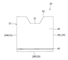
詳細に説明すると、ケース本体22は、テープカートリッジ10のケース12の上面12Uを覆う上壁部24と、ケース12の下面12Dを覆う下壁部26と、ケース12の1つの側面である後面12Bを除く全て(3つ)の側面を覆う側壁部28と、テープカートリッジ10を出入させ、かつケース12の後面12Bを露出させる開口部30と、を有している。
More specifically, the
側壁部28は、ケース12の前面12Fを覆う前壁部28Fと、左面12Lを覆う左壁部28Lと、右面12Rを覆う右壁部28Rと、で構成されている。そして、上壁部24及び下壁部26の開口部30側である後側端部中央には、収納されたテープカートリッジ10を収納ケース20から取り出し易くするために(ケース12の後側を上下から把持し易いように)、平面視で略等脚台形状の切欠部32が形成されている。
The
また、ケース本体22の上壁部24と前壁部28Fと左壁部28Lとが交差する角部には、平面視で略直角三角形状の段差部34が形成されている。この段差部34は、テープカートリッジ10の切欠部14と同等の形状及び寸法に形成されており、テープカートリッジ10が収納ケース20にほぼ隙間無く収納されたときに、切欠部14が段差部34に合致(嵌合)する構成になっている。
In addition, a
これにより、収納ケース20に対するテープカートリッジ10の誤挿入が防止されるようになっている。つまり、テープカートリッジ10が、例えば前後又は上下逆向きに収納ケース20に挿入されたときには、段差部34によって、そのテープカートリッジ10の収納ケース20への挿入が阻止されるようになっている。
As a result, erroneous insertion of the
また、ケース本体22の下壁部26の内面で、かつ前端側には、前壁部28Fの辺縁部に沿って左右方向に延在する断面三角形状の第1凸部36(図2、図8参照)が形成されている。そして、下壁部26の外面で、かつ第1凸部36の表裏反対側となる位置には、断面三角形状の凹部40(図1、図5〜図8参照)が形成されている。更に、上壁部24の外面で、かつ平面視で凹部40と同じ位置には、凹部40に嵌合可能な断面三角形状とされた第2凸部38(図1〜図4、図6〜図8参照)が形成されている。
Further, on the inner surface of the
図8(A)に示されるように、第1凸部36は、テープカートリッジ10が収納ケース20に収納されたときに、そのケース12に形成されている前側端部のスタッキングリブ18を後側から係止する構成になっている。したがって、スタッキングリブ18は、第1凸部36に係止される被係止部にもなっている。これにより、収納ケース20に収納されたテープカートリッジ10が、その収納ケース20から不用意に抜け落ちないようになっている。
As shown in FIG. 8 (A), the
また、図9に示されるように、複数の収納ケース20が積み重ねられるときには、下側の収納ケース20の第2凸部38が、上側の収納ケース20の凹部40に挿入(嵌合)される構成になっている。これにより、複数の収納ケース20が安定的に積み重ねられるようになっている。つまり、収納ケース20が、リールの軸方向と直交する方向(特に前後方向)に位置ずれすることなく、積み重ねられるようになっている。
As shown in FIG. 9, when the plurality of
また、収納ケース20の上壁部24、下壁部26及び側壁部28の少なくとも1つには、テープカートリッジ10に関する情報(図示省略)が外部から視認可能に示されている。具体的には、テープカートリッジ10を使用するときの注意書きや、テープカートリッジ10の製造者、製品情報、記録容量及びデザイン等が収納ケース20の表面に印刷又は成形等によって示されている。
In addition, at least one of the
以上のような構成のテープカートリッジ収納ケース20において、次に、その作用について説明する。
Next, the operation of the tape
テープカートリッジ10を収納ケース20に収納する際には、図1に示されるように、テープカートリッジ10の前側から開口部30内へ挿入する。そして、テープカートリッジ10を収納ケース20に収納させて行くと、ケース12の下面12Dで、かつ前側端部に形成されている左右一対のスタッキングリブ18が、第1凸部36を乗り越えて、その第1凸部36に後側から係止される(図8(A)参照)。
When the
これにより、テープカートリッジ10が、収納ケース20の開口部30から不用意に抜け落ちるのが防止される。なお、第1凸部36は、テープカートリッジ10の挿入方向下流側である前端側に形成されているので、テープカートリッジ10を収納ケース20に挿入した際に、第1凸部36の先端部(上端部)が、テープカートリッジ10の下面12Dに摺接して削れるのが抑制又は防止される。
As a result, the
また、テープカートリッジ10のケース12に形成されている既存のスタッキングリブ18を第1凸部36で係止するので、ケース12に別途スタッキングリブ18とは別の突起部(図示省略)を形成して第1凸部36で係止する構成に比べて、ケース12を成形する金型(図示省略)に設計変更が生じない。つまり、テープカートリッジ10において、製造コストが増加する不具合が起きない。
In addition, since the existing stacking
また、テープカートリッジ10を収納ケース20に収納したとき、テープカートリッジ10の切欠部14が、収納ケース20の段差部34に合致する。これにより、テープカートリッジ10が収納ケース20に正しい姿勢で収納されたことになる。つまり、例えば前後又は上下逆向きにテープカートリッジ10を収納ケース20に挿入したときには、段差部34にケース12の角部が干渉してテープカートリッジ10のそれ以上の挿入が阻止されるので、テープカートリッジ10の向きの異なる誤挿入が防止される。
Further, when the
なお、収納ケース20の上壁部24及び下壁部26の開口部30側である後側端部中央には、切欠部32が形成されているので、収納ケース20からテープカートリッジ10を取り出すときには、テープカートリッジ10の後側を上下から把持し易い。また、スタッキングリブ18が第1凸部36に係止されているだけなので、テープカートリッジ10を収納ケース20から取り出し易い。
Note that a
また、複数個のテープカートリッジ10は、収納ケース20に収納した状態で、リールの軸方向に積み重ねて保管又は搬送することが多い。そのため、複数個の収納ケース20をリールの軸方向に積み重ねるときには、下側の収納ケース20の第2凸部38に、上側の収納ケース20の凹部40を嵌合させる。
In many cases, the plurality of
これによれば、図9に示されるように、複数個の収納ケース20を、リールの軸方向と直交する方向、特に前後方向に位置ずれさせることなく、安定して積み重ねることができる。よって、テープカートリッジ10を収納した収納ケース20の保管時や搬送時に、その収納ケース20が崩れて、収納ケース20内のテープカートリッジ10が、その重みにより落下して破損するような不具合の発生を抑制又は防止することができる。
According to this, as shown in FIG. 9, a plurality of
また、このような凹部40及び第2凸部38によれば、複数個の収納ケース20の各開口部30から露出されているテープカートリッジ10の各後面12Bを一方向に向けて積み重ねることができる。つまり、各テープカートリッジ10の後面12B側に配置されている各メモリーの向きを一律にすることができる。よって、この積み重ねられた複数個の収納ケース20により、簡易な収納棚(ライブラリー装置の一部)を構成することもできる。
Moreover, according to such a recessed
また、この収納ケース20は、第1凸部36の表裏反対側に凹部40が形成されているので、第1凸部36の表裏反対側に凹部40が形成されない構成に比べて、第1凸部36及び凹部40を形成し易い利点がある。つまり、収納ケース20の積み重ね用の凹部40を形成することで、テープカートリッジ10の抜け落ち防止用の第1凸部36を、下壁部26に厚肉部を形成することなく形成できる利点がある。
In addition, since the
また、収納ケース20の上壁部24、下壁部26及び側壁部28の少なくとも1つには、テープカートリッジ10に関する情報が外部から視認可能に示されている。したがって、収納ケース20内に、別途テープカートリッジ10に関する情報が印刷されたインデックスカードやラベル類(共に図示省略)等を、テープカートリッジ10と共に収納する構成に比べて、収納ケース20に収納されて販売されるテープカートリッジ10に係るコストを低減させることができる。
Further, at least one of the
以上、本実施形態に係るテープカートリッジ収納ケース20について、図面を基に説明したが、本実施形態に係るテープカートリッジ収納ケース20は、図示のものに限定されるものではなく、本発明の要旨を逸脱しない範囲内において、適宜設計変更可能なものである。例えば、収納ケース20は、不透明に限定されるものではなく、透明や半透明であってもよい。
The tape
また、第1凸部36及び凹部40は、それぞれ収納ケース20の左壁部28L及び右壁部28Rに達するまで左右方向に延在され、第2凸部38は、段差部34及び右壁部28Rに達するまで左右方向に延在されているが、これに限定されるものではない。第1凸部36、第2凸部38及び凹部40は、それぞれ例えば図示のものよりも若干短く形成されていてもよいし、断続的に形成されていてもよい。但し、第1凸部36が前壁部28Fの辺縁部に沿って左右方向に延在されていると、例えばテープカートリッジ10の種類によってスタッキングリブ18の左右方向の位置が異なっていても、そのスタッキングリブ18を係止できる利点がある。
The first
また、第1凸部36、第2凸部38及び凹部40の形状は、断面三角形状に限定されるものではなく、例えば断面四角形状等とされていてもよい。更に、第1凸部36、第2凸部38及び凹部40の数量も、図示の各1つに限定されるものではない。また、収納ケース20に収納されるテープカートリッジ10には、メモリーの他に、又はメモリーの代わりに、読み取り専用のRFID(Radio Frequency IDentification)等が内蔵されていてもよい。
Moreover, the shape of the 1st
10 テープカートリッジ
12 ケース
12U 上面
12D 下面
12B 後面(1つの側面)
14 切欠部
18 スタッキングリブ(被係止部/突起部)
20 テープカートリッジ収納ケース
22 ケース本体
24 上壁部
26 下壁部
28 側壁部
30 開口部
34 段差部
36 第1凸部
38 第2凸部
40 凹部
10
14
DESCRIPTION OF
Claims (6)
前記下壁部における前記テープカートリッジの挿入方向下流側の内面に形成され、前記テープカートリッジの挿入状態で前記下面に形成された被係止部を係止する第1凸部と、
前記下壁部の外面で、かつ前記第1凸部の表裏反対側となる位置に形成された凹部と、
前記上壁部の外面で、かつ平面視で前記凹部と同じ位置に該凹部に嵌合可能な形状に形成された第2凸部と、
を備えたテープカートリッジ収納ケース。 An upper wall portion covering the upper surface of the tape cartridge, a lower wall portion covering the lower surface of the tape cartridge, a side wall portion covering all side surfaces except one side surface of the tape cartridge, and allowing the tape cartridge to enter and exit, and A case body having an opening that exposes one side surface;
A first protrusion that is formed on the inner surface of the lower wall portion on the downstream side in the insertion direction of the tape cartridge and that locks the locked portion formed on the lower surface in the inserted state of the tape cartridge;
A concave portion formed on the outer surface of the lower wall portion and on the opposite side of the first convex portion; and
A second convex part formed on the outer surface of the upper wall part and in a shape that can be fitted into the concave part at the same position as the concave part in plan view;
Tape cartridge storage case with
前記第1凸部が前記ケース本体における前記テープカートリッジの挿入方向下流側の辺縁部に沿って形成されている請求項2に記載のテープカートリッジ収納ケース。 A plurality of the protrusions are formed;
The tape cartridge storage case according to claim 2, wherein the first convex portion is formed along a side edge portion of the case body on the downstream side in the insertion direction of the tape cartridge.
Priority Applications (2)
| Application Number | Priority Date | Filing Date | Title |
|---|---|---|---|
| JP2015098340A JP6389798B2 (en) | 2015-05-13 | 2015-05-13 | Tape cartridge storage case |
| US15/151,504 US10083717B2 (en) | 2015-05-13 | 2016-05-11 | Tape cartridge housing case |
Applications Claiming Priority (1)
| Application Number | Priority Date | Filing Date | Title |
|---|---|---|---|
| JP2015098340A JP6389798B2 (en) | 2015-05-13 | 2015-05-13 | Tape cartridge storage case |
Publications (3)
| Publication Number | Publication Date |
|---|---|
| JP2016210493A JP2016210493A (en) | 2016-12-15 |
| JP2016210493A5 JP2016210493A5 (en) | 2017-09-14 |
| JP6389798B2 true JP6389798B2 (en) | 2018-09-12 |
Family
ID=57277596
Family Applications (1)
| Application Number | Title | Priority Date | Filing Date |
|---|---|---|---|
| JP2015098340A Active JP6389798B2 (en) | 2015-05-13 | 2015-05-13 | Tape cartridge storage case |
Country Status (2)
| Country | Link |
|---|---|
| US (1) | US10083717B2 (en) |
| JP (1) | JP6389798B2 (en) |
Family Cites Families (9)
| Publication number | Priority date | Publication date | Assignee | Title |
|---|---|---|---|---|
| JPS4926577Y1 (en) * | 1970-06-18 | 1974-07-18 | ||
| CH556589A (en) * | 1972-09-06 | 1974-11-29 | Idn Invention Dev Novelties | CONTAINER FOR ACCEPTING A CASSETTE WITH A TAPE-SHAPED RECORDING MEDIA. |
| JPS5452430U (en) * | 1977-09-18 | 1979-04-11 | ||
| JPS59142954U (en) * | 1983-03-14 | 1984-09-25 | 大日本印刷株式会社 | video cassette case |
| JPH0516990A (en) | 1991-07-03 | 1993-01-26 | Konica Corp | Package of tape cassette case and index card |
| JPH0558689U (en) * | 1992-01-18 | 1993-08-03 | コニカ株式会社 | Case for tape cassette |
| JPH0877746A (en) * | 1994-08-31 | 1996-03-22 | Sony Corp | Recording medium housing cassette and cassette keeping case and label adhered thereto |
| JP3973782B2 (en) * | 1998-11-12 | 2007-09-12 | 富士フイルム株式会社 | Cassette storage case |
| JP3971791B2 (en) * | 2000-09-29 | 2007-09-05 | 日立マクセル株式会社 | Storage case for tape cartridge |
-
2015
- 2015-05-13 JP JP2015098340A patent/JP6389798B2/en active Active
-
2016
- 2016-05-11 US US15/151,504 patent/US10083717B2/en active Active
Also Published As
| Publication number | Publication date |
|---|---|
| US10083717B2 (en) | 2018-09-25 |
| JP2016210493A (en) | 2016-12-15 |
| US20160336038A1 (en) | 2016-11-17 |
Similar Documents
| Publication | Publication Date | Title |
|---|---|---|
| US6640972B2 (en) | Cassette storing case | |
| JP3971791B2 (en) | Storage case for tape cartridge | |
| JP6389798B2 (en) | Tape cartridge storage case | |
| US10896697B2 (en) | Recording tape cartridge storage case and storage case containing recording tape cartridges | |
| JP2007204083A (en) | Cartridge housing case | |
| JP5028877B2 (en) | Storage medium storage box, storage medium storage system, and method of using storage medium storage system | |
| EP0537678B1 (en) | Container case for magnetic tape cassette | |
| US10867232B2 (en) | Recording tape cartridge storage case and storage case containing recording tape cartridge | |
| JP4544539B2 (en) | Storage case for tape cartridge | |
| JP2007197074A (en) | Cartridge accommodating case | |
| JP5783882B2 (en) | Electronics | |
| JP2004010095A (en) | Cassette storage case | |
| JPH0620913B2 (en) | Box-shaped pivotable case for record carrier | |
| JP5271253B2 (en) | Memory card tray and disk case with memory card tray | |
| JP2005251327A (en) | Information carrier housing case | |
| JP2003077254A (en) | Recording tape cartridge | |
| JPH11278579A (en) | Cartridge storage case | |
| JP2007204090A (en) | Cartridge storage case | |
| JP2002284276A (en) | Disk cartridge housing case | |
| JP2007045441A (en) | Packaging container | |
| JP2007204086A (en) | Cartridge storage case | |
| JP2005239216A (en) | Storing case for tape cassette | |
| JP2003085932A (en) | Recording tape cartridge | |
| JP2010173676A (en) | Storage case for recording medium | |
| JPH10338286A (en) | Housing case for minidisk |
Legal Events
| Date | Code | Title | Description |
|---|---|---|---|
| A521 | Request for written amendment filed |
Free format text: JAPANESE INTERMEDIATE CODE: A523 Effective date: 20170807 |
|
| A621 | Written request for application examination |
Free format text: JAPANESE INTERMEDIATE CODE: A621 Effective date: 20170807 |
|
| A977 | Report on retrieval |
Free format text: JAPANESE INTERMEDIATE CODE: A971007 Effective date: 20180425 |
|
| A131 | Notification of reasons for refusal |
Free format text: JAPANESE INTERMEDIATE CODE: A131 Effective date: 20180508 |
|
| A521 | Request for written amendment filed |
Free format text: JAPANESE INTERMEDIATE CODE: A523 Effective date: 20180601 |
|
| TRDD | Decision of grant or rejection written | ||
| A01 | Written decision to grant a patent or to grant a registration (utility model) |
Free format text: JAPANESE INTERMEDIATE CODE: A01 Effective date: 20180724 |
|
| A61 | First payment of annual fees (during grant procedure) |
Free format text: JAPANESE INTERMEDIATE CODE: A61 Effective date: 20180820 |
|
| R150 | Certificate of patent or registration of utility model |
Ref document number: 6389798 Country of ref document: JP Free format text: JAPANESE INTERMEDIATE CODE: R150 |
|
| R250 | Receipt of annual fees |
Free format text: JAPANESE INTERMEDIATE CODE: R250 |
|
| R250 | Receipt of annual fees |
Free format text: JAPANESE INTERMEDIATE CODE: R250 |
|
| R250 | Receipt of annual fees |
Free format text: JAPANESE INTERMEDIATE CODE: R250 |