JP6385318B2 - Transform 3D objects to segment objects in 3D medical images - Google Patents
Transform 3D objects to segment objects in 3D medical images Download PDFInfo
- Publication number
- JP6385318B2 JP6385318B2 JP2015168093A JP2015168093A JP6385318B2 JP 6385318 B2 JP6385318 B2 JP 6385318B2 JP 2015168093 A JP2015168093 A JP 2015168093A JP 2015168093 A JP2015168093 A JP 2015168093A JP 6385318 B2 JP6385318 B2 JP 6385318B2
- Authority
- JP
- Japan
- Prior art keywords
- scale
- dimensional
- filter
- image
- kernel
- Prior art date
- Legal status (The legal status is an assumption and is not a legal conclusion. Google has not performed a legal analysis and makes no representation as to the accuracy of the status listed.)
- Expired - Fee Related
Links
- 238000000034 method Methods 0.000 claims description 118
- 210000001165 lymph node Anatomy 0.000 claims description 102
- 230000011218 segmentation Effects 0.000 claims description 69
- 230000009467 reduction Effects 0.000 claims description 30
- 230000009466 transformation Effects 0.000 claims description 17
- 230000001131 transforming effect Effects 0.000 claims description 14
- 230000003902 lesion Effects 0.000 claims description 10
- 238000006243 chemical reaction Methods 0.000 claims description 6
- 238000009826 distribution Methods 0.000 claims description 5
- 238000013459 approach Methods 0.000 claims description 4
- 206010028980 Neoplasm Diseases 0.000 claims description 3
- 230000008569 process Effects 0.000 description 56
- 230000008859 change Effects 0.000 description 11
- 238000004422 calculation algorithm Methods 0.000 description 9
- 238000002591 computed tomography Methods 0.000 description 8
- 238000004364 calculation method Methods 0.000 description 7
- 230000006870 function Effects 0.000 description 7
- 238000010586 diagram Methods 0.000 description 4
- 230000005484 gravity Effects 0.000 description 4
- 238000002372 labelling Methods 0.000 description 4
- 238000007781 pre-processing Methods 0.000 description 4
- 210000001519 tissue Anatomy 0.000 description 4
- 230000008901 benefit Effects 0.000 description 3
- 238000001914 filtration Methods 0.000 description 3
- 238000004458 analytical method Methods 0.000 description 2
- 230000001419 dependent effect Effects 0.000 description 2
- 238000001514 detection method Methods 0.000 description 2
- 238000002059 diagnostic imaging Methods 0.000 description 2
- 238000009499 grossing Methods 0.000 description 2
- 238000012804 iterative process Methods 0.000 description 2
- 230000000877 morphologic effect Effects 0.000 description 2
- 238000011946 reduction process Methods 0.000 description 2
- 238000009877 rendering Methods 0.000 description 2
- 238000003860 storage Methods 0.000 description 2
- 238000004590 computer program Methods 0.000 description 1
- 230000007423 decrease Effects 0.000 description 1
- 238000005516 engineering process Methods 0.000 description 1
- 230000002708 enhancing effect Effects 0.000 description 1
- 238000013213 extrapolation Methods 0.000 description 1
- 238000003384 imaging method Methods 0.000 description 1
- 230000001788 irregular Effects 0.000 description 1
- 238000002620 method output Methods 0.000 description 1
- 230000000116 mitigating effect Effects 0.000 description 1
- 210000000056 organ Anatomy 0.000 description 1
- 230000001902 propagating effect Effects 0.000 description 1
- 238000007670 refining Methods 0.000 description 1
- 238000004904 shortening Methods 0.000 description 1
- 230000036962 time dependent Effects 0.000 description 1
- 238000003325 tomography Methods 0.000 description 1
- 238000000844 transformation Methods 0.000 description 1
- 238000011426 transformation method Methods 0.000 description 1
- 238000002604 ultrasonography Methods 0.000 description 1
- 230000000007 visual effect Effects 0.000 description 1
Images


Classifications
-
- G—PHYSICS
- G06—COMPUTING; CALCULATING OR COUNTING
- G06T—IMAGE DATA PROCESSING OR GENERATION, IN GENERAL
- G06T7/00—Image analysis
- G06T7/10—Segmentation; Edge detection
- G06T7/168—Segmentation; Edge detection involving transform domain methods
-
- G—PHYSICS
- G06—COMPUTING; CALCULATING OR COUNTING
- G06T—IMAGE DATA PROCESSING OR GENERATION, IN GENERAL
- G06T15/00—3D [Three Dimensional] image rendering
- G06T15/10—Geometric effects
- G06T15/20—Perspective computation
-
- G—PHYSICS
- G06—COMPUTING; CALCULATING OR COUNTING
- G06T—IMAGE DATA PROCESSING OR GENERATION, IN GENERAL
- G06T7/00—Image analysis
-
- G—PHYSICS
- G06—COMPUTING; CALCULATING OR COUNTING
- G06T—IMAGE DATA PROCESSING OR GENERATION, IN GENERAL
- G06T7/00—Image analysis
- G06T7/10—Segmentation; Edge detection
-
- G—PHYSICS
- G06—COMPUTING; CALCULATING OR COUNTING
- G06T—IMAGE DATA PROCESSING OR GENERATION, IN GENERAL
- G06T7/00—Image analysis
- G06T7/10—Segmentation; Edge detection
- G06T7/11—Region-based segmentation
-
- G—PHYSICS
- G06—COMPUTING; CALCULATING OR COUNTING
- G06T—IMAGE DATA PROCESSING OR GENERATION, IN GENERAL
- G06T7/00—Image analysis
- G06T7/10—Segmentation; Edge detection
- G06T7/12—Edge-based segmentation
-
- G—PHYSICS
- G06—COMPUTING; CALCULATING OR COUNTING
- G06T—IMAGE DATA PROCESSING OR GENERATION, IN GENERAL
- G06T7/00—Image analysis
- G06T7/10—Segmentation; Edge detection
- G06T7/149—Segmentation; Edge detection involving deformable models, e.g. active contour models
-
- G—PHYSICS
- G06—COMPUTING; CALCULATING OR COUNTING
- G06T—IMAGE DATA PROCESSING OR GENERATION, IN GENERAL
- G06T2207/00—Indexing scheme for image analysis or image enhancement
- G06T2207/10—Image acquisition modality
- G06T2207/10072—Tomographic images
- G06T2207/10081—Computed x-ray tomography [CT]
-
- G—PHYSICS
- G06—COMPUTING; CALCULATING OR COUNTING
- G06T—IMAGE DATA PROCESSING OR GENERATION, IN GENERAL
- G06T2207/00—Indexing scheme for image analysis or image enhancement
- G06T2207/10—Image acquisition modality
- G06T2207/10116—X-ray image
-
- G—PHYSICS
- G06—COMPUTING; CALCULATING OR COUNTING
- G06T—IMAGE DATA PROCESSING OR GENERATION, IN GENERAL
- G06T2207/00—Indexing scheme for image analysis or image enhancement
- G06T2207/20—Special algorithmic details
- G06T2207/20112—Image segmentation details
- G06T2207/20161—Level set
-
- G—PHYSICS
- G06—COMPUTING; CALCULATING OR COUNTING
- G06T—IMAGE DATA PROCESSING OR GENERATION, IN GENERAL
- G06T2207/00—Indexing scheme for image analysis or image enhancement
- G06T2207/30—Subject of image; Context of image processing
- G06T2207/30004—Biomedical image processing
- G06T2207/30096—Tumor; Lesion
Description
本発明は、画像中の対象物のセグメンテーションに関し、特に医用画像中のリンパ節、病変、結節又は腫瘍などの対象物のセグメンテーションに関する。 The present invention relates to segmentation of the object in the image, especially the lymph nodes in the medical image, the lesion, to segmentation of objects, such as nodules or tumors.
セグメンテーションは、デジタル画像中の対象物の形状又は境界を認識する技術である。セグメンテーションの目的は、例えば時間の経過に伴って画像ごとに対象物が変化したか否かを判定するために、画像(医用画像など)中の対象物の表現を変えることである。このセグメンテーションを実現する技術は数多く存在するが、それらの技術は、画像中のコントラストの範囲、対象物と背景とのコントラストの程度、対象物のスケール、すなわち相対的サイズ、画像データのフォーマットなどに従って適切であるものもあれば、さほど適切ではないものもある。しかし、多くの技術に共通しているのは、画像中の各画素(3D画像ではボクセル)に、特定の視覚的特性(グレイスケール、輝度など)に対応する何らかの種類のラベルが割り当てられることである。従って、同一の又は類似するラベルを割り当てられた画素(ボクセル)は、何らかの理由により、例えば同一の構造(例えば、同一の対象物)の一部であることを示すために、観測者により1つにまとまったものとみなされてもよい。 Segmentation is a technique for recognizing the shape or boundary of an object in a digital image. The purpose of segmentation is, for example, to change the representation of an object in an image (such as a medical image) to determine whether the object has changed for each image over time. There are many techniques for realizing this segmentation , but these techniques depend on the range of contrast in the image, the degree of contrast between the object and the background, the scale of the object, ie the relative size, the format of the image data, etc. Some are appropriate, others are not. However, what is common to many technologies is that each pixel in the image (voxel in 3D images) is assigned some type of label that corresponds to a particular visual characteristic (grayscale, brightness, etc.). is there. Thus, a pixel (voxel) assigned the same or similar label is, for some reason, eg one by the observer to indicate that it is part of the same structure (eg the same object). It may be regarded as a group.
「塊状構造(ブロブ)検出」として知られる種類のセグメンテーションは、T.Lindebergの「Feature detection with automatic scale selecton」(International Journal of Computer Vision、第30巻、79〜116ページ、1998年)に記載されている。この論文では、画像中の塊状構造の相対位置及びスケールを判定するためにガウシアンモデルのラプラシアン演算子(ラプラシアンオブガウシアン又はLoG演算子又は A type of segmentation known as “blob detection” is described in T.W. Lindberg, “Feature detection with automatic scale select” (International Journal of Computer Vision, Vol. 30, pages 79-116, 1998). In this paper, the Laplacian operator (Laplacian of Gaussian or LoG operator or Gaussian model) is used to determine the relative position and scale of massive structures in an image.
A.Jirapatnakul、S.Fotin他の「Automated Nodule Location and Size Estimation Using a Multi−scale Laplacian of Gaussian Filter
ing Approach」(Annual International Conference of the IEEE EMBS、1028〜1031ページ、2009年)は、塊状構造のサイズを推定するために塊状構造の中心付近に位置する開始点からラプラシアンオブガウシアンフィルタ処理を適用することを説明している。
A. Jirapatnakul, S .; Foton et al., “Automated Nodule Location and Size Estimating Using a Multi-scale Laplacian of Gaussian Filter.
ing Approach "(Annual International Conference of the IEEE EMBS, pages 1028-1031, 2009) applies Laplacian of Gaussian filtering from a starting point located near the center of the massive structure to estimate the size of the massive structure Explain that.
以上挙げた2つの技術では、異なるスケール(以下に説明されるシグマ値)を反復検査し、対象の塊状構造のスケールとして最も可能性の高いスケールを発見するLoGフィルタを使用して、塊状構造のスケールの全体的推定が発見される。1次元では、スケールは原点から塊状構造の推定縁部までの距離であってもよく、2次元では、スケールは塊状構造を表す円の半径であってもよく、3次元では、スケールは塊状構造を表す球の半径であってもよい。LoGフィルタにより判定されるスケールは、中心位置に対するコントラスト変化の位置に基づく。コントラストの変化は塊状構造の縁部に存在すると想定される。「領域成長」方式は、各画素を中心点から外側へ解析し、対象物を識別するために使用されるパラメータに各画素が従うか否かを判定する。パラメータに従う画素が発見されなくなった場合、画素がパラメータに従わなくなった位置が対象物の縁部に対応する位置であると想定される。 The two techniques listed above use a LoG filter to iteratively inspect different scales (sigma values described below) and find the most likely scale for the target massive structure, An overall estimate of the scale is found. In one dimension, the scale can be the distance from the origin to the estimated edge of the massive structure, in two dimensions, the scale can be the radius of a circle representing the massive structure, and in three dimensions, the scale can be a massive structure. May be the radius of a sphere representing. The scale determined by the LoG filter is based on the position of the contrast change with respect to the center position. It is assumed that the contrast change is present at the edge of the massive structure. The “region growth” method analyzes each pixel outward from the center point and determines whether each pixel follows the parameters used to identify the object. When no pixel according to the parameter is found, it is assumed that the position where the pixel no longer follows the parameter is the position corresponding to the edge of the object.
セグメンテーションされる対象物のスケールを推定するためにLoG演算を使用する。この「スケール推定」処理は、セグメンテーションには有用なツールである。例えば領域成長方式では、対象物の近似最大サイズがわかっているので(すなわち、推定されたスケールにより発見された特定の領域の外側では、対象物に含めるためのパラメータに従う画素が存在する可能性は低いので)、スケール推定を使用して、過剰な領域膨張を抑制することができる(すなわち、中心点から外側に向かって徐々に画素を解析する処理)。しかし、スケール推定処理において問題が起こる可能性もある。問題の1つは計算時間が非常に長いというリスクであ
る。先に説明したLoGフィルタを使用する方法のような従来のスケール推定方法の場合、広い処理範囲(すなわち、広い探索空間)全体にわたり、範囲内のすべての点に対してLoGフィルタが適用されるので、計算時間は非常に長い。一般に、スケール推定は、処理範囲内の点の数に関連するパラメータを変化させ、点ごとにスケールを生成させる反復処理である。その後、すべての計算結果から1つの適切なスケールを判定するのであるが、広い処理範囲に対する計算結果の数は多くなるかもしれない。
A LoG operation is used to estimate the scale of the object being segmented . This “scale estimation” process is a useful tool for segmentation . For example, in the region growing method, the approximate maximum size of the object is known (ie, outside the specific area found by the estimated scale, there is a possibility that there will be pixels according to the parameters to include in the object. Since it is low, scale estimation can be used to suppress excessive region expansion (ie, the process of gradually analyzing pixels from the center point outward). However, problems may occur in the scale estimation process. One problem is the risk that the computation time is very long. In the case of a conventional scale estimation method, such as the method using the LoG filter described above, the LoG filter is applied to all points within the range over a wide processing range (ie, a wide search space). The calculation time is very long. In general, the scale estimation is an iterative process in which a parameter related to the number of points in the processing range is changed and a scale is generated for each point. Then, one appropriate scale is determined from all the calculation results, but the number of calculation results for a wide processing range may be large.
セグメンテーション処理の次のステップ(スケール推定ステップの後)は、領域成長方法を含むセグメンテーションであってもよい。対象物を定義するために選択された基準を点が満たすか否かを判定するために、中心の「シード」点から関心領域内のすべての点が解析される。その基準を満たすすべての点が対象物に属すると判定される。 The next step in the segmentation process (after the scale estimation step) may be a segmentation that includes a region growing method. To determine whether a point meets the criteria selected to define the object, all points in the region of interest are analyzed from the central “seed” point. It is determined that all points that meet the criteria belong to the object.
これに代わるセグメンテーション処理が使用されてもよい。この処理は、S.Osher及びJ.Sethianの「Fronts Propagating with Curvature−Dependent Speed:Algorithm Based on Hamilton−Jacobi Formulations」(Journal of Com
putational Physics、第79巻、12〜49ページ、1988年)及びJ.Sethianの「Level Set Method 1st Ed.」(Cambridge University Press、1996年)で説明されているようなレベルセットアルゴリズムを含んでもよい。これらの文献は、曲率依存速度で伝搬するフロントを定義するアルゴリズムを説明する。これを実行する方法は、「運動」(空間内の1つの次元における変化を表す時間依存メタファとして使用される)を予測する面をとらえ、輪郭を定義するために、その面を平面と交差させる。例えば球は、平面上で円を
定義するために、その平面によって赤道付近で二等分されてもよい。この輪郭(例えば、円)は、時間t=0で定義可能な形状を有し、時間の経過に伴って、この輪郭がどのように変化するかを定義するために(例えば、平面が球の赤道から極へ移動するにつれて、円の直径は減少する)、tの変化に伴ってフロントが進む(例えば、内側へ)方向を定義するように、球のフロント(すなわち球の周囲)に力が加えられる。
An alternative segmentation process may be used. This process is described in S.A. Osher and J.M. Sethian's “Fronts Propagating with Curve-Dependent Speed: Algorithm Based on Hamilton-Jacobi Formulas” (Journal of Com
putative physics, 79, 12-49, 1988) and J. Am. It may also include a level set algorithm as described in Sethian's “Level Set Method 1st Ed.” (Cambridge University Press, 1996). These documents describe algorithms that define a front that propagates at a curvature-dependent velocity. The way to do this is to take a surface that predicts "motion" (used as a time-dependent metaphor representing changes in one dimension in space) and intersect that plane with a plane to define a contour. . For example, a sphere may be bisected near the equator by the plane to define a circle on the plane. This contour (eg, a circle) has a shape that can be defined at time t = 0 and to define how this contour changes over time (eg, the plane is a sphere) As the circle moves from the equator to the pole, the diameter of the circle decreases), and forces are applied to the front of the sphere (ie around the sphere) to define the direction in which the front advances (eg, inwards) as t Added.
例えば、人体の中の1つの対象物の3次元表現を提供するために組み合わされるコンピュータ断層撮影(CT)スキャンのような一連の医用画像の場合、レベルセットアルゴリズムは3次元対象物の外面を定義するために使用されてもよい。しかし、これを実行するためには、まず、3次元画像を構成しているすべての画像の中の対象物の縁部が決定されなければならない。 For example, in the case of a series of medical images such as a computed tomography (CT) scan combined to provide a three-dimensional representation of one object in the human body, the level set algorithm defines the outer surface of the three-dimensional object. May be used to However, in order to do this, the edges of the object in all the images making up the 3D image must first be determined.
中心シード点から領域成長などのセグメンテーション処理を使用して対象物の縁部を発見することは知られている。中心シードから、対象物に関する事前に定義されたパラメータ(例えば、テクスチャ、色、輝度など)を持たない画素に到達するまで外側に向かいながら、シードの近傍画素に反復処理が適用される。隣接するが、所定のパラメータを満たさない画素に到達した場合、対象物の縁部に達したと想定される。3次元対象物形状を構成するために、多数の並列する画像に領域成長処理が適用されてもよい。レベルセットアルゴリズムは、ユーザが画像ごとにシード点を入力する必要を軽減することにより、処理を少なくするのを助ける。アルゴリズムは、3D形状全体を構成するために限られた数の対象物縁部を使用することにより、この軽減を実現する。 It is known to find the edge of an object using a segmentation process such as region growth from a central seed point. The iterative process is applied to the neighboring pixels of the seed, going outward from the central seed until it reaches a pixel that does not have a predefined parameter for the object (eg, texture, color, brightness, etc.). When a pixel that is adjacent but does not satisfy a predetermined parameter is reached, it is assumed that the edge of the object has been reached. In order to construct a three-dimensional object shape, a region growing process may be applied to a large number of parallel images. The level set algorithm helps reduce processing by reducing the need for the user to enter seed points for each image. The algorithm achieves this mitigation by using a limited number of object edges to construct the entire 3D shape.
これらのスケール推定処理及びセグメンテーション処理に関する問題点の1つは、セグメンテーションされるリンパ節などの対象物が完全な球体であるのは稀であるということである。従って、リンパ節が3次元の対称形であることに基づく仮定は、セグメンテーション処理において大きな不正確さを生み出す可能性がある。例えば3次元の長さがそれぞれ異なるリンパ節に3次元(3D)LoGフィルタが適用された場合、LoGフィルタは、リンパ節のスケールを、それらの長さのうち1つの長さの2分の1に等しい半径を有する球であると推定しがちであり、球の半径は、単に、反復処理中にどの画素定義縁部が最初に発見されたか又はLoGフィルタの出力のどのLoG「ピーク」が最初に発見されたか、あるいはどの「ピーク」が最も高いかに依存しているにすぎない(ピークは、画素パラメータの変化を定義し、従って、対象物の縁部である尤度が高い)。 One problem with these scale estimation and segmentation processes is that objects such as lymph nodes to be segmented are rarely complete spheres. Thus, assumptions based on the lymph node being three-dimensional symmetric can create significant inaccuracies in the segmentation process. For example, if a three-dimensional (3D) LoG filter is applied to lymph nodes with different three-dimensional lengths, the LoG filter will scale the lymph nodes to one-half of their length. The radius of the sphere is simply determined which pixel-defined edge was first found during the iteration or which LoG “peak” of the output of the LoG filter was the first. Or only depends on which “peak” is the highest (the peak defines the change of the pixel parameter and is therefore likely to be the edge of the object).
米国特許第7,333,644号公報は、病変の重心位置に基づいて、3D病変面を球面座標空間の面表現に補間することを説明している。従って、補間は、座標を直交座標(x,y,z)から球面座標r(φ,θ)に変化させる変換を含む。この補間処理は、サブボリューム(病変及びその周囲環境を含む)を等方性にすること、すなわちx−yスライスの画素の寸法をz方向の画素の寸法と同一にさせることを意図する。これにより、作業の基礎となる座標系はわずかに容易になるが、不規則な形状の対象物の問題には対応していない。さらに、球面座標のすべてのパラメータは重心に依存するので、重心が固定され
ていない限り、球面座標は各ボクセルの位置を表現することができない。従って、面倒な処理であることに変わりはない。
US Pat. No. 7,333,644 describes interpolating a 3D lesion surface into a surface representation of a spherical coordinate space based on the position of the center of gravity of the lesion. Interpolation thus includes transformations that change the coordinates from orthogonal coordinates (x, y, z) to spherical coordinates r (φ, θ). This interpolation process is intended to make the subvolume (including the lesion and its surrounding environment) isotropic, that is, to make the pixel size of the xy slice the same as the pixel size in the z direction. This makes the coordinate system underlying the work slightly easier, but does not address the problem of irregularly shaped objects. Furthermore, since all parameters of the spherical coordinates depend on the center of gravity, the spherical coordinates cannot represent the position of each voxel unless the center of gravity is fixed. Therefore, it is still a troublesome process.
上記の問題点を考慮すると、対象物が不規則な形状である場合に、対象物をセグメンテーションが実行される非等方性であるが、規則的形状の対象物に変換することにより、セグメンテーション中の処理負荷を軽減する装置及び方法を提供することが望ましい。 In view of the above problems, the case where the object is an irregular shape, is non-isotropic segmentation is executed an object by converting the object of regular shape, in segmentation It would be desirable to provide an apparatus and method that reduces the processing load.
本発明の第1の態様によれば、セグメンテーションの方法であって、当初ボリューム中の対象物の表面を推定するステップと、規則的形状の(好ましくはほぼ球形の)面をレンダリングするために対象物の表面を変換するステップと、対象物を背景ボリュームからセグメンテーションするために、ほぼ球形の面を処理するステップと、ほぼ球形の表面を当初の対象物の表面に逆変換するステップと、当初ボリュームから対象物に対応するボリュームを抽出するステップとを備える方法が提供される。 According to a first aspect of the present invention, there is provided a segmentation method for estimating a surface of an object in an initial volume, and for rendering a regularly shaped (preferably substantially spherical) surface. Transforming the surface of the object; processing a substantially spherical surface to segment the object from the background volume; converting the substantially spherical surface back to the surface of the original object; and the initial volume. Extracting a volume corresponding to the object from the method.
非等方性ではあっても、対象物を球面形状に変換することの利点は、対象物に対して実行される解析を3つの次元すべてで対称に実行できるために、対象物を背景ボリュームから更に容易に隔離できることである。立方体又は他の規則的形状が使用されてもよいことは言うまでもない。 The advantage of converting an object to a spherical shape, even if it is anisotropic, is that the analysis performed on the object can be performed symmetrically in all three dimensions, so that the object is removed from the background volume. Furthermore, it can be easily isolated. Of course, cubes or other regular shapes may be used.
対象物の面の変換は、対象物の面の各次元をその他の次元から独立させて変換することを含むのが好ましい。例えば対象物の面の各次元に異なる関数が適用される。関数は次のように計算されてもよい。対象物の3次元スケール推定値Scale3D spaceを取得し、対象物の次元ごとの1次元スケール推定値Scaleeach directionを取得し、式:

しかし、各次元の1次元スケール推定が特定の次元の3次元スケールより小さい場合、縮小率SR1は1.0であるのが好ましい。これは、推定後の対象物のどの次元に関しても、サイズの増加を阻止する。逆に、(例えば)ユーザが対象物の周囲にバウンディングボックス又は境界形状を挿入することにより、1つの次元のスケールが発見され、この次元が3次元スケール推定値より大きいとわかった場合、この1つの次元のみに縮小率SR1を適用させる。 However, when the one-dimensional scale estimation of each dimension is smaller than the three-dimensional scale of a specific dimension, the reduction ratio SR1 is preferably 1.0. This prevents an increase in size for any dimension of the object after estimation. Conversely, if (for example) the user inserts a bounding box or boundary shape around the object, a one-dimensional scale is found and this dimension is found to be greater than the three-dimensional scale estimate, this one The reduction ratio SR1 is applied to only one dimension.
この変換は、対象物の表面を球などの非等方性の規則的な形状に変換することを目的とする。これを実行する方法の1つは、異なる次元で画素ピッチを変化させることである。第1の次元は、当初の画像画素ピッチを有してもよい。第2の次元は、第1の縮小率SR1だけ減少された画素ピッチを有してもよく、第3の次元は、第2の縮小率SR1だけ減少された画素
ピッチ、又は別の率により拡大された画素ピッチを有してもよいだろう。しかし、その結果、規則的な3D形状となる。
The purpose of this conversion is to convert the surface of the object into an anisotropic regular shape such as a sphere. One way to do this is to change the pixel pitch in different dimensions. The first dimension may have an initial image pixel pitch. The second dimension may have a pixel pitch reduced by a first reduction rate SR1 , and the third dimension may be enlarged by a pixel pitch reduced by a second reduction rate SR1 , or by another rate. It would be possible to have a reduced pixel pitch. However, the result is a regular 3D shape.
あるいは、この変換は、2次元画像中の対象物をセグメンテーションするために2つの次元に適用されてもよい。 Alternatively, this transformation may be applied in two dimensions to segment the objects in the two-dimensional image.
上記のステップに続いて、球面を逆変換することは、対象物の各次元に縮小率SR1の逆数を乗算することを含んでもよい。 Subsequent to the above steps, inverse transforming the sphere may include multiplying each dimension of the object by the inverse of the reduction factor SR1 .
対象物の表面の推定は、いくつかの方法で実行されてもよい。好適な方法は、入力された境界形状を使用して処理範囲を計算し、次に、その処理範囲内の点にLoGフィルタを適用する。LoGフィルタは、1次元、2次元又は3次元でスケールを推定するための1次元カーネル、2次元カーネル又は3次元カーネルを有してもよい。境界形状は2次元で入力される場合が多いので、境界形状の1つの次元に基づいて3次元における対象物スケールの1回目の粗推定を実行し、次に、更なる処理範囲の基礎として粗推定を使用して、推定を精密化する(特に境界形状が対応していない第3の次元で)のが好ましい。例えば3次元カーネルを使用した3次元の1回目の粗推定に基づいて、次元ごとに1次元カーネルを使用して更に精密なスケール推定を取得するために、1次元、2次元又は3次元に対して処理範囲が計算されてもよい。言い換えれば、境界形状は、粗スケール推定のための第1の処理範囲を提供してもよく、その後、粗スケール推定は、より精密な更なるスケール推定のための第2の処理範囲を計算するために使用される。粗スケール推定及び精密化スケール推定は、1次元カーネル、2次元カーネル又は3次元カーネルを有するLoGフィルタによって実行されてもよい。 The estimation of the surface of the object may be performed in several ways. The preferred method uses the input boundary shape to calculate a processing range, and then applies a LoG filter to points within that processing range. The LoG filter may have a one-dimensional kernel, a two-dimensional kernel, or a three-dimensional kernel for estimating the scale in one, two, or three dimensions. Since the boundary shape is often input in two dimensions, a first rough estimation of the object scale in three dimensions is performed based on one dimension of the boundary shape, and then rough as a basis for further processing range. It is preferable to use the estimation to refine the estimation (especially in the third dimension where the boundary shape does not correspond). For example, to obtain a more accurate scale estimate using a 1D kernel for each dimension, based on a 3D first coarse estimate using a 3D kernel, for 1D, 2D or 3D The processing range may be calculated. In other words, the boundary shape may provide a first processing range for coarse scale estimation, after which the coarse scale estimation calculates a second processing range for more precise further scale estimation. Used for. Coarse scale estimation and refinement scale estimation may be performed by a LoG filter having a one-dimensional kernel, a two-dimensional kernel, or a three-dimensional kernel.
本発明の第2の態様によれば、画像から対象物をセグメンテーションする方法であって、画像を受信することと、対象物のスケール推定を実行することとを備え、対象物のスケール推定を実行することは、対象物の周囲に境界形状を入力することと、境界形状に基づいて処理エリアを規定することと、対象物の推定スケールを取得するために、処理エリア内でスケール推定を実行することとを含み、方法は、対象物を規則的形状に変換することと、対象物を表す規則的形状を推定するための粗セグメンテーションと、規則的形状に基づいて対象物の形状を精密化するためのレベルセット法を含む精密セグメンテーションと、対象物を当初ボリュームに逆変換することと、対象物の精密化形状を画像から抽出することとを更に備える方法が提供される。 According to a second aspect of the present invention, there is provided a method for segmenting an object from an image, the method comprising receiving an image and performing scale estimation of the object, and performing scale estimation of the object Doing input a boundary shape around the object, defining a processing area based on the boundary shape, and performing scale estimation within the processing area to obtain an estimated scale of the object The method includes converting the object into a regular shape, coarse segmentation for estimating the regular shape representing the object, and refining the shape of the object based on the regular shape and precision segmentation including level set method for, and to inverse transform the object initially volume, further methods provide and a extracting a refined shape from an image of the object It is.
本発明の第3の態様によれば、3次元画像から対象物をセグメンテーションする画像処理装置であって、当初ボリューム中の対象物の表面を推定する手段と、規則的形状の面をレンダリングするために対象物の表面を変換する手段と、対象物を背景ボリュームからセグメンテーションするために、規則的形状の表面を処理する手段と、規則的形状の表面を当初の対象物の表面に逆変換する手段と、当初ボリュームから対象物に対応するボリュームを抽出する手段とを備える装置が提供される。このような装置は、X線装置又はCT(コンピュータ断層撮影)装置のような医療用撮影モダリティのコンピュータ又は更にはプロセッサであってもよい。
添付の図面を参照して、以下に本発明を単なる例によって説明する。
According to a third aspect of the present invention, there is provided an image processing apparatus for segmenting an object from a three-dimensional image, the means for estimating the surface of the object in the initial volume, and for rendering a regularly shaped surface. Means for transforming the surface of the object into, means for processing the regularly shaped surface to segment the object from the background volume, and means for converting the regularly shaped surface back to the surface of the original object And a device for extracting a volume corresponding to the object from the initial volume. Such a device may be a medical imaging modality computer such as an X-ray device or a CT (Computerized Tomography) device or even a processor.
The invention will now be described by way of example only with reference to the accompanying drawings.
以下の説明は、コンピュータ断層撮影(CT)画像のような3次元医用画像からリンパ節をセグメンテーションするための好適な実施形態を説明する。説明される実施形態を病変、腫瘍又は結節などの他の対象物、あるいは医用画像で認識可能な他の対象物にも使用できることは言うまでもない。 The following description describes a preferred embodiment for segmenting lymph nodes from 3D medical images such as computed tomography (CT) images. It goes without saying that the described embodiments can also be used for other objects such as lesions, tumors or nodules, or other objects recognizable in medical images.
好適な実施形態は、対象物のスケールを推定するように対象物画像に対してラプラシアンオブガウシアン(LoG)フィルタ処理を実行するために、ボリューム(3次元又は3D)画像中の関心領域(ROI)を操作することを含む順序処理に従う。対象物のスケールが推定された後、セグメンテーション処理中に処理しやすい対象物形状を提供するために、ROIは変換される。次に、シード領域が定義され、対象物画像に領域成長セグメンテーション方法が適用されるが、その閾値及びシード領域は推定されたスケールに基づき、最終的には、レベルセット処理を使用してセグメンテーションが精密化され、対象物を当初のスケールに戻すためにROIが逆変換された後、セグメンテーション済み対象物は表示される。以下に説明される実施形態は、主にセグメンテーション処理に最適な形状を提供するためのボリューム画像中の関心領域の変換に関する。 A preferred embodiment provides a region of interest (ROI) in a volume (3D or 3D) image to perform Laplacian of Gaussian (LoG) filtering on the object image to estimate the scale of the object. Follow the order process including manipulating the. After the scale of the object is estimated, the ROI is transformed to provide an object shape that is easy to process during the segmentation process. Next, a seed region is defined and a region growing segmentation method is applied to the object image, but the threshold and seed region are based on the estimated scale, and finally segmentation is performed using a level set process. After being refined and the ROI inverted to return the object to its original scale, the segmented object is displayed. The embodiments described below relate primarily to the transformation of regions of interest in volume images to provide an optimal shape for the segmentation process.
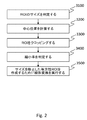
3次元画像データセットからリンパ節をセグメンテーションする好適な処理が図1に示され、この処理を以下に説明する。2次元画像データセットからリンパ節をセグメンテーションする場合にも、類似の処理を適用できる。 A preferred process for segmenting lymph nodes from a 3D image data set is shown in FIG. 1 and is described below. Similar processing can be applied when segmenting lymph nodes from a two-dimensional image data set.
図1に示される第1のステップ1000は、CTスキャナ、超音波スキャナ、X線検出器などのモダリティ又は撮影デバイスに接続されたコンピュータのようなプロセッサを使用して画像を取得する。ステップ2000において、ユーザは、そのような画像を見ながら、対象リンパ節を識別するための情報を入力する。この情報は、リンパ節の中央にある中心点又は好ましくはリンパ節の外周に沿った「バウンディングボックス」を含んでもよい。情報は、ユーザインタフェースと、マウス、タッチスクリーン、ジョイスティック又はキーボードなどの入力手段とを使用して入力されてもよい。バウンディングボックスは、正方形、矩形、円形又はユーザにより入力可能な何らかの形状であってもよい。以下の特定の実施形態は、矩形のバウンディングボックスが入力されたか、又はユーザにより入力された中心点に基づいてプロセッサにより正方形のバウンディングボックスが外挿されたという仮定に基づく。
The
識別後、関心リンパ節は、以下の4つのモジュールを含むセグメンテーション処理を受ける。 After identification, the lymph node of interest undergoes a segmentation process that includes the following four modules:
1. ステップ3000の前処理
2. ステップ4000のスケール推定
3. ステップ5000の粗セグメンテーション
4. ステップ6000の精密化
最終的に、ステップ7000において、プロセッサは、ハードドライブ又は他のその種のメモリなどの記憶手段にセグメンテーション結果を記憶し、コンピュータ画面又は他のデジタルディスプレイなどの表示手段に結果を表示する。
1. 1. Pre-processing of
好適な実施形態は、スケール推定に際して従来の技術の処理範囲とは異なる処理範囲を指定する、ユーザにより入力されるバウンディングボックスを使用する。指定される処理範囲は、関心領域全体ではなく、好適な実施形態では、LoGフィルタのピークがリンパ節の縁部により高い可能性で対応し且つ偽ピークの尤度が低減されるようにリンパ節の縁部と重なり合うことが意図される環形状(又は3次元では中空の芯を有する球形)である。3つの次元で処理範囲を取得するために、画像データセットの3つの次元すべてに対して、これと同一の方法が適用されてもよい(この処理範囲から、3つの次元でスケール推定が発見されてもよい)。あるいは、3次元のスケール推定値は、3つの次元すべてで処理範囲を発見し且つ3つの次元すべてでスケール推定を実行するステップを経過せずに、2つの次元で推定されたスケールから外挿されてもよい。この第2の方法は時間を節約できるが、第3の次元で精度が低くなる危険がある。 The preferred embodiment uses a bounding box entered by the user that specifies a processing range different from the processing range of the prior art for scale estimation. The processing range specified is not the entire region of interest, and in a preferred embodiment the lymph nodes so that the peak of the LoG filter corresponds more likely to the edge of the lymph node and the likelihood of false peaks is reduced. Ring shape (or a sphere with a hollow core in three dimensions) that is intended to overlap the edges of the. The same method may be applied to all three dimensions of the image data set to obtain a processing range in three dimensions (from this processing range scale estimates are found in three dimensions). May be) Alternatively, the three-dimensional scale estimate is extrapolated from the scale estimated in the two dimensions without passing through the steps of finding processing ranges in all three dimensions and performing the scale estimation in all three dimensions. May be. This second method saves time, but there is a risk that accuracy will be reduced in the third dimension.
バウンディングボックスは、粗スケール推定のための第1の処理範囲を提供するのが好ましく、粗スケール推定は、更に精密なスケール推定のための第2の処理範囲を計算するために使用される。粗スケール推定及び精密スケール推定は、1次元カーネル、2次元カーネル又は3次元カーネルを有するLoGフィルタによって実行されてもよい。 The bounding box preferably provides a first processing range for coarse scale estimation, and the coarse scale estimation is used to calculate a second processing range for more precise scale estimation. Coarse scale estimation and fine scale estimation may be performed by a LoG filter having a one-dimensional kernel, a two-dimensional kernel, or a three-dimensional kernel.
バウンディングボックスを使用して、この更に正確な処理範囲を指定する好適な方法は、図1の4ステップセグメンテーション処理3000〜6000に関連して以下に説明される。 A preferred method of specifying this more accurate processing range using bounding boxes is described below in connection with the four-step segmentation process 3000-6000 of FIG.
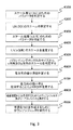
第1のモジュールである前処理モジュール3000自体は、図2に示され且つ以下に挙げられるように5つのステップを含む。
The first module, the
1.ステップ3100において、リンパ節の周囲の関心領域(ROI)のサイズを判定する。ROIは当初画像からクロッピングされる。ROIのサイズは、一般に、ユーザにより入力されたx−y平面の2次元(2D)バウンディングボックスに基づいて判定される。画像が2D画像である場合、ROIは、バウンディングボックスの中のエリアであってもよく、又は(更に多くの場合に)バウンディングボックスを含む更に広いエリアであってもよい。画像が3D画像である場合、ROIは、第3の次元でバウンディングボックスを外挿することにより、又は3Dバウンディングボックスを形成するために、ユーザに2つ以上の(多くの場合に平行な)画像でバウンディングボックスを入力させることにより定義される3Dボリュームであってもよい。
1. In
あるいは、ROIはユーザにより選択された中心点の周囲の特定のサイズ及び特定の形状であってもよく、特定のサイズ及び特定の形状は必要に応じて、医用画像のスケールに従ってリンパ節サイズの対象物を含むように判定されてもよい。例えばROIは、2D画像の中で、ユーザ入力中心点の周囲に現実の患者の3cm×3cmに対応するサイズとして指定されてもよい。あるいは、ROIは3D画像の中で現実の患者の3cm×3cm×3cmに対応するサイズとして指定されてもよい。 Alternatively, the ROI may be a specific size and a specific shape around the center point selected by the user, the specific size and the specific shape being subject to a lymph node size according to the scale of the medical image, if necessary. It may be determined to include an object. For example, the ROI may be specified as a size corresponding to 3 cm × 3 cm of the actual patient around the user input center point in the 2D image. Alternatively, the ROI may be specified as a size corresponding to 3 cm × 3 cm × 3 cm of an actual patient in the 3D image.
一般にバウンディングボックスは、リンパ節の位置を識別するためにユーザにより入力され、バウンディングボックスは、ほぼリンパ節の大きさであるか又はそれよりわずかに大きいと推定される。好適な実施形態において、ROIの大きさは、バウンディングボックスの辺の長さのうち長いほうの辺とほぼ等しい辺の長さを有するとして指定される。図8は、バウンディングボックスBBにより取り囲まれたリンパ節LNの一例を示す。バウンディングボックスのx方向長さ及びy方向長さが判定される。一貫性と説明を容易にするために、バウンディングボックスの最長の辺をバウンディングボックスの「幅」と呼ぶ。一実施形態において、測定された幅は5つの範囲のうち1つに該当し、各範囲は以下の式を使用して、ボクセル数で測定された立方体ROIの辺の長さを生成する。
式中、HWidthBBは、式(2)により表され、同様にボクセル数で測定されるバウンディングボックスの半幅である。
In the formula, HWidthBB is represented by the formula (2), and is the half width of the bounding box similarly measured by the number of voxels.
典型的なバウンディングボックスのサイズ及び関連するROIの結果の妥当性に基づいて、他の何らかの適切な閾値が選択されてもよいことは言うまでもない。システムは、履歴データに基づいて、ROIとバウンディングボックスの幅とのどのような関連付けが適切であるかを「学習」してもよい。 Of course, any other suitable threshold may be selected based on the size of the typical bounding box and the validity of the associated ROI result. The system may “learn” what association between the ROI and the bounding box width is appropriate based on historical data.
ROIのサイズ及びバウンディングボックスの半幅は1次元(立方体の部)で測定されるが、ボクセル数でカウントされる。この段階のROIは、バウンディングボックスより大きいが、リンパ節を正確に取り囲んでいないバウンディングボックスをユーザが入力した場合でも、リンパ節全体を含むことが多い。 The size of the ROI and the half width of the bounding box are measured in one dimension (cube part), but are counted by the number of voxels. The ROI at this stage is larger than the bounding box, but often includes the entire lymph node even if the user enters a bounding box that does not accurately surround the lymph node.
従って、70ボクセルの幅を有するとしてバウンディングボックスが入力された場合、式(2)に従ったHWidthBB=35ボクセルであり、式(1)に従ったROIの縁部の長さは111ボクセルとなる。 Therefore, if a bounding box is input as having a width of 70 voxels, HWidthBB = 35 voxels according to equation (2), and the length of the ROI edge according to equation (1) is 111 voxels. .
2.図2のステップ3200において、リンパ節の中心位置が発見される。リンパ節の中心位置を発見する最も速い方法は、バウンディングボックスの中心をリンパ節の中心とみなすことである。あるいは、ユーザがリンパ節の中心点を指示していたのであれば、その点を中心位置とみなすことができるのは言うまでもない。従って、ROIの中心は、可能な限りリンパ節の中心と一致するようにされる。
2. In
3.ステップ3300において、ROIは、ステップ3100及び3200でそれぞれ判定されたサイズ(バウンディングボックスから計算されたROIのサイズ)及び位置(中心位置又はバウンディングボックスの位置)に基づいて当初のボリューム画像からクロッピングされる(すなわち、「切り取られる」又は「隔離される」)。
3. In
4、ステップ3400において、ステップ3500でクロッピング済みROIに適用される縮小率SR2が判定される。この縮小率SR2は、ROI(リンパ節を含む)のサイズを変更し且つROIを等方性にするために使用される。等方性にすることの利点は、1つの次元で実行される計算を他の次元に適用でき、それにより処理負荷を軽減できることである。縮小率SR2は、バウンディングボックスの半幅により判定され、次の式(3)により表される。
5.最後に、ステップ3500において、ステップ3400で判定された縮小率SR2によりROIサイズを操作することにより、ROIはサイズ変更され、等方性にされる。従って、バウンディングボックスが70ボクセルの幅である場合、その半幅は35ボクセルであり、縮小率SR2は2/3である。そこで、サイズ変更後のROIの辺の長さは、111の2/3に等しい74ボクセルになる。縮小処理は分解能を低下させるが、それにより処理時間を短縮するための処理である。縮小処理中、リンパ節も縮小される。
5. Finally, in
セグメンテーションシステムの第2のモジュール4000は、スケール推定モジュールである。LoGフィルタは、LoG演算子により定義される球の内側と外側との間の輝度分布のコントラストを使用することによりリンパ節LNのスケールを推定する(球のサイズは、ガウシアンフィルタのシグマσ値により決定される)。これに対し、後に説明するセグメンテーション処理における対象物の縁部は、隣接ボクセルの間のコントラストから計算される。
The
LoGフィルタは、中央から開始して外側に向かって反復処理しながら、処理範囲内のあらゆる点を処理する。最も効率のよい反復処理にするために、処理範囲は可能な限り小さく(可能な限り少ない数の点を含む)、しかもリンパ節の縁部が処理範囲内に含まれるように十分な数の点を含むのが好ましい。これを実現する方法は、リンパ節の位置及び/又はリンパ節のサイズのうち少なくとも一方を推定することである。処理範囲が最小であり且つ最も精密であるように正確な位置とサイズを知るのが最も正確であることは言うまでもない。 The LoG filter processes every point in the processing range, starting from the center and iterating outwards. To achieve the most efficient iteration, the treatment area is as small as possible (including as few points as possible) and enough points so that the edges of the lymph nodes are within the treatment area Is preferably included. A way to achieve this is to estimate at least one of lymph node location and / or lymph node size. Needless to say, it is most accurate to know the exact position and size so that the processing range is the smallest and most precise.
スケール推定は、全画像データに関するリンパ節のサイズ及び相対位置の推定である。
スケール推定モジュール4000により実行される処理は、図3に示されるステップ4100〜4900にセグメンテーションされ、以下に説明される。
Scale estimation is an estimate of the size and relative position of the lymph nodes with respect to the entire image data.
The processing performed by the
図3のステップ4100は、スケール推定処理で使用されるパラメータを決定することを含む。決定されるパラメータには様々な種類がある。第1の種類のパラメータは、画像中のその他の部分からセグメンテーションされる関心点群(すなわちリンパ節)に属する点を定義する種類のパラメータである。従って、それらのパラメータは、リンパ節を表す画素/ボクセルの輝度、テクスチャなどの範囲であることが可能だろう。前述のように、他の種類のパラメータは、画像のその他の部分に関してリンパ節がとりそうな位置及び画像のその他の部分に関してリンパ節が示しそうなサイズを含む。
このステップ4100で判定される別のパラメータは、画像のその他の部分に関するリンパ節の相対位置である。リンパ節の位置を発見する方法の1つは、中心点(例えば、質量の中心)を発見することである。ユーザにより入力されたバウンディングボックスの中心点が使用されてもよい。これは、画面上でユーザに1つの中心点を指定させる場合より一般に正確である。
Another parameter determined in this
リンパ節のスケールを発見するために、ROI内の面積/容積全体が処理される。 To find the lymph node scale, the entire area / volume within the ROI is processed.
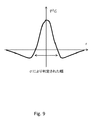
LoGフィルタは、輝度の変化が大きい(すなわちコントラストが高い)位置にピークを有する図12に示されるようなヒストグラムを生成する。特に、ピークは、LoGのガウシアンフィルタのシグマσ値により定義される球の内側と外側との間に高いコントラストが存在することを意味する。そのようなピークは対象物の縁部で通常起こるが、LoGフィルタ出力値のヒストグラムは、誤って縁部として解釈される他の輝度変化点にもピークを有する。あるいは、対象物の縁部が中心点から異なる距離にある場合、異なるシグマσの値に対して、すなわちLoGフィルタの異なる開始点に対して、ヒストグラムで異なるピークが示されるかもしれない。そのようなピークが図12に示される。 The LoG filter generates a histogram as shown in FIG. 12 having a peak at a position where the luminance change is large (that is, the contrast is high). In particular, the peak means that there is a high contrast between the inside and outside of the sphere defined by the sigma σ value of the LoG Gaussian filter. Such peaks usually occur at the edges of the object, but the histogram of LoG filter output values also has peaks at other luminance change points that are misinterpreted as edges. Alternatively, if the edges of the object are at different distances from the center point, different peaks may be shown in the histogram for different sigma σ values, ie for different starting points of the LoG filter. Such a peak is shown in FIG.
図12は、ヒストグラム上に処理範囲(網目部分)を示し、y軸にLoGフィルタの出力値∇2G*Iを示す。Gはガウスフィルタ関数である。σは標準偏差である。x軸のσは、ガウス分布のサイズを定義するために使用されるガウスフィルタ関数のパラメータの
1つである。従って、σが変化した場合、ガウス分布のサイズは変化する。すなわち、LoGフィルタのスケール(LoG演算子のサイズ)は変化する。∇2Gは、以下に説明されるラプラシアンオブガウシアン演算子である。このヒストグラムをどのようにして取得するかは、図4に示されるステップ4211に関連して以下に説明される。
FIG. 12 shows the processing range (mesh portion) on the histogram, and the LoG filter output value ∇2G * I on the y-axis. G is a Gaussian filter function. σ is a standard deviation. The x-axis σ is one of the parameters of the Gaussian filter function used to define the size of the Gaussian distribution. Therefore, when σ changes, the size of the Gaussian distribution changes. That is, the scale of the LoG filter (the size of the LoG operator) changes. ∇2G is a Laplacian of Gaussian operator described below. How to obtain this histogram is described below in connection with
スケール推定のためのパラメータが決定されたならば、ステップ4200はリンパ節のスケールを推定する。スケールの更に具体的な判定方法は、ステップ4500に関連して後に説明されるが、第1のステップは、3次元でリンパ節のスケールを推定することを含む。図4を参照して、スケール推定処理の詳細を説明する。
Once the parameters for scale estimation have been determined,
ステップ4210は、動的パラメータ(σ)による反復フィルタリング処理(ステップ4211及び4212を繰り返す)である。好適な実施形態において、ラプラシアンオブガウシアン(LoG)フィルタは、リンパ節のスケールを推定するために使用される。ステップ4211は、縮小ROIに対してLoGフィルタを実行することを含む。LoGフィルタのアルゴリズムは次の通りである。
・まず、入力画像にガウシアンフィルタが適用される。
・次に、ガウス平滑化画像にラプラシアンフィルタ(2次微分フィルタ)が適用される。
First, a Gaussian filter is applied to the input image.
Next, a Laplacian filter (secondary differential filter) is applied to the Gaussian smoothed image.
上記の処理を次の式により表すことができる。
式中、I(x,y,z)は入力画像であり、Gはガウシアンフィルタを表す。
The above processing can be expressed by the following equation.
In the equation, I (x, y, z) is an input image, and G represents a Gaussian filter.
式(4)において、右辺は、画像I(x,y,z)中の半径rの入力ROIに対して∇2Gカーネル(LoGカーネル)が適用されることを意味する。図9はガウシアンカーネルの2次の微分であるLoGカーネルを示す。LoGカーネルの幅(サイズ)はシグマσ値により決定される。リンパ節を含むROIにLoGフィルタが適用されると、LoGカーネルの幅σがリンパ節の幅と一致する場合、リンパ節の中心の出力値∇2Gは大きな値をとる。 In Expression (4), the right side means that the 2G kernel (LoG kernel) is applied to the input ROI having the radius r in the image I (x, y, z). FIG. 9 shows the LoG kernel which is the second derivative of the Gaussian kernel. The width (size) of the LoG kernel is determined by the sigma σ value. When the LoG filter is applied to the ROI including the lymph node, the output value ∇2G at the center of the lymph node takes a large value when the width σ of the LoG kernel matches the width of the lymph node.
次に、ステップ4212において、ステップ4211で先に記録された最大LoGフィルタ出力値より大きい出力値がある場合、シグマσ値及び最大のLoGフィルタ出力値を有する対応するボクセル位置が更新される。この最大のLoGフィルタ出力値及び関連するシグマσ値は、リンパ節の中心に位置するボクセルに対応すると想定され、これにより、修正中心位置が決定される。
Next, in
Nが処理近傍における開始点の数に対応する場合、ステップ4211及び4212はN回繰り返される。これらのステップは、σ(シグマ)値を変化させながらLoGフィルタを繰り返し適用する。すなわち、LoGフィルタは処理範囲内の各点に順次適用される。最大のLoGフィルタ出力値を出力したσ値から、リンパ節の近似スケールを知ることができる。σ値は、式(5)により標準偏差からボクセル値に変換される。
式中、Paramsigmaは、ステップ4100で判定されるスケール推定の処理範囲内で変化するパラメータ(すなわち、ROIの中心からの距離)を表す。Paramsigmaの単位はボクセルである。先に説明したように、σはガウシアンフィルタで使用される標準偏差である。式(5)はσ値をボクセル値から取得するために使用される。すなわち、処理範囲の半径を5ボクセル、6ボクセル、7ボクセルからnボクセルまで増分変化させながら、適切なスケールが反復的に探索される場合、式(5)はボクセル値からσ値に変換するので、そのような値(ボクセル単位で測定される長さ)をParamsigmaに入力できる。A.Jirapatnakul及びS.Fotinによる論文には、この式はd2=12σ2として表されており、「d」は結節の直径である。
If N corresponds to the number of starting points in the vicinity of the process, steps 4211 and 4212 are repeated N times. These steps apply the LoG filter repeatedly while changing the σ (sigma) value. That is, the LoG filter is sequentially applied to each point within the processing range. The approximate scale of the lymph node can be known from the σ value obtained by outputting the maximum LoG filter output value. The σ value is converted from a standard deviation to a voxel value by equation (5).
In the equation, Parasigma represents a parameter (that is, a distance from the center of the ROI) that changes within the processing range of the scale estimation determined in
Paramsigmaの値は、反復処理中に1ずつ増分される。従って、反復回数はスケール推定の処理範囲の大きさに応じて決定される。 The value of Parasigma is incremented by 1 during the iteration process. Therefore, the number of iterations is determined according to the size of the scale estimation processing range.
反復処理4210の終了後、システムは、共に最大のLoGフィルタ出力値を有する(すなわち、図12のヒストグラムにおけるピーク)σ値及びボクセル位置を判定でき、この値はリンパ節のスケール及び中心位置を表すと想定される。
After completion of the
図4のステップ4220において、ステップ4210の結果から、リンパ節のスケール及び/又は中心位置が判定される。この場合のスケールはリンパ節の半径であってもよく、そこで、ステップ4210から出力されたシグマ値は半径に変換され、それにより、リンパ節の推定スケールが提供される。最大のLoGフィルタ出力値を有するボクセル位置はリンパ節の中心位置になる。次に、決定されたリンパ節のスケール及び/又は中心位置は、図3に示されるスケール推定の次のステップで使用されてもよい。
In
更なる実施形態によれば、定義された処理範囲内でリンパ節のサイズを推定できない場合、処理範囲は小さすぎるか又は不正確に位置決めされたと想定される。従って、更に広い範囲で、スケール推定処理が再度実行される。範囲を拡張する方法はいくつかあり、他の類似する処理の(ログ)履歴又は更なるユーザ入力に基づいて、それらの方法のうち1つ以上が選択されてもよい。例えば通常、バウンディングボックスが予想より小さく形成された場合、バウンディングボックスの半幅から開始するのではなく、バウンディングボックスの60%又は70%、あるいは他の割合の幅から開始されるように処理範囲又は処理近傍を拡張する方法が選択されてもよい。 According to a further embodiment, if the size of the lymph node cannot be estimated within the defined processing area, it is assumed that the processing area is too small or incorrectly positioned. Therefore, the scale estimation process is executed again in a wider range. There are several ways to extend the range, and one or more of those methods may be selected based on the (log) history of other similar processes or further user input. For example, usually when the bounding box is formed smaller than expected, the processing range or processing should start from 60% or 70% of the bounding box, or some other width, instead of starting from the half width of the bounding box. A method for extending the neighborhood may be selected.
図3及びスケール推定処理に戻ると、ステップ4300は、3D画像の場合にz方向スケール推定処理のためのパラメータを決定することを含む。
Returning to FIG. 3 and the scale estimation process,
x方向及びy方向のリンパ節のスケールを推定するために使用されるバウンディングボックスは言うまでもなくx−y平面でのみユーザにより入力されるので、z方向のリンパ節のスケールは、ユーザの入力によっては示唆されない。従って、z方向(第3の次元とも呼ばれる)のリンパ節のスケールを推定するために、更なるステップが実行されてもよい。 The bounding box used to estimate the x- and y-direction lymph node scales is, of course, entered by the user only in the xy plane, so the z-direction lymph node scale is dependent on the user's input. Not suggested. Thus, further steps may be performed to estimate the scale of the lymph nodes in the z direction (also called the third dimension).
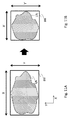
z方向のスケールを推定する方法の1つは、x−y平面のスケール推定を使用し、例えば円が球になるように、そのスケール推定をz方向に外挿することである。これは、図10Bに示されるような形状のリンパ節に当てはまる。この図において、矢印100は、x−y平面のスケール推定からの外挿を使用して推定されたスケールの半径を示す。
One way to estimate the scale in the z direction is to use a scale estimate in the xy plane and extrapolate the scale estimate in the z direction, for example so that the circle is a sphere. This is true for lymph nodes shaped as shown in FIG. 10B. In this figure,
この場合に起こりうる問題は、図10Aに示されるように、リンパ節がx方向又はy方向よりz方向に著しく長い場合の例からわかる。 A possible problem in this case can be seen from the example where the lymph nodes are significantly longer in the z direction than in the x or y direction, as shown in FIG. 10A.
z方向のスケールを推定する第2の方法は、x−y平面に関して決定された処理範囲を使用し、この処理範囲に基づいてz方向のスケール推定(例えば、LoGフィルタを使用して)を実行することである。リンパ節がほぼ球形である場合、この方法は、先の場合と同様に効率よく機能するだろう。 A second method for estimating the z-direction scale uses a processing range determined with respect to the xy plane, and performs z-direction scale estimation (eg, using a LoG filter) based on the processing range. It is to be. If the lymph nodes are approximately spherical, this method will work as efficiently as before.
しかし、この第2の方法でも、リンパ節が使用される処理範囲よりz方向に著しく長い(又は実際に著しく短い)場合に問題が起こる可能性がある。 However, even with this second method, problems can arise if the lymph nodes are significantly longer (or actually much shorter) in the z-direction than the treatment range in which they are used.
従って、好適な一実施形態は、x方向及びy方向のスケール推定とは異なる開始点でz方向のスケールを推定する。好適な実施形態は、z方向のスケール推定パラメータを決定することから始めて、x方向及びy方向に関して実行されたようなスケール推定のステップをz方向に関しても実行する。 Thus, one preferred embodiment estimates the z-direction scale at a different starting point than the x- and y-direction scale estimates. The preferred embodiment begins with determining the z-direction scale estimation parameters and performs the scale estimation steps for the z-direction as performed for the x-direction and the y-direction.
ステップ4300で判定されるパラメータは、ステップ4100のパラメータと同一であるが、z方向のパラメータである。各パラメータを決定するための式は、ステップ4100の式とほぼ同一である。境界形状を使用してスケールを推定するために使用された式との相違点は、「HWidthBB・SR」がステップ4200で出力されたリンパ節のスケール推定値と置き換えられることである(これは更に精密なスケールの推定値である)。更に、リンパ節の中心点に関する処理近傍は(0,0,修正z)へシフトされ、このステップでは、スケール推定処理はz方向でのみ計算される。「修正z」処理範囲は、
により示される。
The parameters determined in
Indicated by.
式中、Scalein 3D spaceは、先に説明したようにステップ4200からのリンパ節の3Dスケール推定値である。式(6)において、Paramshiftingは、HWidthBB・SR(境界形状に基づいてスケールを推定するときに使用される)をScalein 3D spaceと置き換えることにより再計算される。
Where Scalein 3D space is the 3D scale estimate of the lymph node from
図3のステップ4400は、おそらくはz方向のリンパ節の中心位置の修正を含めて、リンパ節のz方向スケールを推定する処理を含む。このステップのアルゴリズムはステップ4200とほぼ同一である。z方向のスケール推定及びz方向の中心位置修正において、システムは、LoGフィルタの計算においてz方向(1次元)LoGカーネルを使用する。特に、ステップ4200のLoGカーネルは3次元カーネルであるが、このステップのLoGカーネルは1次元カーネルである。
従って、ステップ4200の終了時には、リンパ節のスケールは3次元のすべてで等しいと推定される(バウンディングボックスの最長の幅に基づいて)。ステップ4400の終了時、z方向のスケールは、3Dスケール推定値に基づいて更に正確に且つ個別に推定されている。各次元で個別に正確な推定値を取得するために、更なる(代替又は追加)ステップが実行される。特に、ステップ4500において、各方向のリンパ節のスケールは更に具体的に判定される。ここで、各方向は、互いに異なると共に、個別に計算され、ステップ4200のように3次元空間で計算されるためにステップ4200において推定されたスケールとも異なる個別のx方向、y方向及びz方向のスケールを意味する。従ってz方向スケールは、先にステップ4400に関して説明したように計算されており、このステップ4500においてx方向のスケール及びy方向のスケールは、x方向のバウンディングボックスの長さ及びy方向のバウンディングボックスの長さによりそれぞれ定義される。従って、先に説明した処理は、x方向及びy方向の双方に使用されたバウンディングボックスの最長の長さではなく、各方向の長さが独立して定義される。
Thus, at the end of
ステップ4200で初期3D推定を判定する代わりに、まず、1次元LoGカーネルを使用してx方向及びy方向のスケールを個別に推定することが可能であり、z方向のスケールを推定するために、推定されたスケールの平均(又は他の関数)が使用されてもよい。いずれの方法も、z方向にはバウンディングボックスが描かれていないということを考慮に入れて、z方向のリンパ節のスケールを推定するための開始点を提供することを意図する。あるいは、リンパ節の2次元スケール推定を取得するために2次元LoGカーネルが使用されてもよく、その後、このスケール推定は、1次元、2次元又は3次元で更に精密なスケール推定のための処理範囲を提供するために使用される。
Instead of determining the initial 3D estimate in
次に、ステップ4600において、各方向の縮小率が計算される。各方向の縮小率(SR1each direction)は次の式により計算される。
式中、Scaleeach directionは、ステップ4400又は4500で算出される、ボクセル単位で測定された各方向のスケールである。各方向の縮小率SR1each direction(以下単にSR1という場合がある)は、システムがx方向縮小率、y方向縮小率及びz方向縮小率の3つの縮小率を取得するように、すべての方向で独立して計算される。この操作の意図は、すべての方向で同様に操作できる(セグメンテーション処理、領域成長及びレベルセットにより)が、操作後に当初のリンパ節スケールを取得するために個別の縮小率SR1によって再成長させることが可能な非等方性リンパ節を作成することである。
Next, in
In the equation, Scaleeach direction is a scale in each direction, measured in voxel units, calculated in
式(7)は、各方向のスケール(ステップ4500の出力)が3D空間のスケール(ステップ4200の出力)より大きい場合に適用される。各方向のスケールが3D空間のスケールより小さい場合、個別のスケールが全体的な推定スケールと同一になるように、縮小率SR1は「1.0」とする。逆に、ユーザが(例えば)バウンディングボックス又は境界形状を対象物の周囲に挿入することにより1つの次元のスケールが発見され、このスケールが3次元スケール推定より大きいことが判明した場合、この1つの特定の次元にのみ縮小率SR1が適用される。 Equation (7) is applied when the scale in each direction (output of step 4500) is larger than the scale of 3D space (output of step 4200). When the scale in each direction is smaller than the scale in the 3D space, the reduction ratio SR1 is set to “1.0” so that the individual scale is the same as the overall estimated scale. Conversely, if a user finds a one-dimensional scale by (for example) inserting a bounding box or boundary shape around the object and finds that this scale is greater than the three-dimensional scale estimate, this one The reduction ratio SR1 is applied only to a specific dimension.
図3のステップ4700は、ステップ4600で計算された各方向の縮小率SR1を使用してROIを変換することを含む。変換されるROIの幅、高さ及び奥行(すなわち3つの次元)に、それぞれの縮小率SR1が乗算される。次に、修正後の幅、高さ及び奥行に従って、線形変換法が実行される。図10Aは、人体の中及び3D画像データに現れる場合のリンパ節LNを示す。推定スケール及び対応する縮小率SR1を使用する縮小変換は、図10Bの非等方性であるが、ほぼ球形のリンパ節を提供するために適用される。これらの図において、陰影をつけた領域LNは、バウンディングボックスBBを使用してステップ4200でスケールが推定されたx−y平面のリンパ節である。長いほうの矢印110は、z方向に推定されたスケールを表す(ステップ4400)。この場合、z方向に推定されたスケールは、3D空間で推定されたスケール(ステップ4200)より大きい。従って、リンパ節に図10Bに示される等方性スケール(しかしボクセルは非等方性)を与えるために、ROIは、z方向により大きく縮小される。球形は画像処理に好都合であるので、z方向に長いリンパ節の形状は、球を近似するためにz方向に最も大きく縮小される。この変換を実行する理由は、スケール推定の実行後、画像をセグメンテーションする準備が整うことである。従来の技術とは異なり、本発明の実施形態の方法は、変換処理に際して対象物の重心の情報を使用しない。ここで説明される方法は、対象物を含む空間を直交座標空間から、空間重心の情報を必要としない修正直交座標空間に変換する。
言い換えれば、ここで説明される方法は、等方性空間から非等方性空間への「非等方性変換」を実行する。 In other words, the method described here performs an “anisotropic transformation” from an isotropic space to an anisotropic space.
この変換の前、スケール推定方法は前処理で作成された等方性画像を扱っていた。変換中、各ボクセルの間のピッチは等方性から非等方性に変化される。従って、変換により、対象物の形状(すなわち表面)は、セグメンテーションが更に容易になるように変換される。リンパ節の第1の次元は当初の画像画素ピッチを有してもよく、第2の次元は第1の率だけ減少された画素ピッチを有してもよく、第3の次元は第2の率だけ減少されるか又は別の率だけ拡大された画素ピッチを有してもよい。しかし、その結果は、規則的な3次元ではあるが非等方性の形状である。 Prior to this transformation, the scale estimation method handled an isotropic image created by preprocessing. During conversion, the pitch between each voxel is changed from isotropic to anisotropic. Thus, by transformation, the shape of the object (ie, the surface) is transformed so that segmentation is further facilitated. The first dimension of the lymph node may have an original image pixel pitch, the second dimension may have a pixel pitch reduced by a first rate, and the third dimension may be a second It may have a pixel pitch that is reduced by a factor or enlarged by another factor. However, the result is a regular three-dimensional but anisotropic shape.
あるいは、この変換は、2次元画像中の対象物をセグメンテーションするために2つの次元に適用されてもよい。 Alternatively, this transformation may be applied in two dimensions to segment the objects in the two-dimensional image.
図10Aは、z方向に長い形状を有する対象物の形状の一例を示す。z方向の正確なスケールは、入力された境界形状BBに基づいて3D空間で推定されたスケールより大きい。図10Aの対象物がセグメンテーションのためにイメージプロセッサに入力された場合、使用されるセグメンテーション方法が3D空間で推定されたスケールを使用して制約条件を考慮に入れるので、イメージプロセッサはz方向に正確なセグメンテーションを実行できない。 FIG. 10A shows an example of the shape of an object having a long shape in the z direction. The exact scale in the z direction is larger than the scale estimated in 3D space based on the input boundary shape BB. When the object of Figure 10A is input to the image processor for segmentation, since using a scale segmentation method used is estimated in 3D space into account the constraints, the image processor precisely in the z direction Unsuccessful segmentation .
z方向に正確なセグメンテーションを取得するために、まずステップ4300及び4400に関連して説明したように、z方向のスケールが推定される。次に、推定されたz方向のスケールに従って病変を変換するための関数が追加される。図10Bは変換後の対象物を表す。変換後の病変は球形状に近似される。この変換は、セグメンテーションにおいて単純な制約条件を使用できることを意味する(セグメンテーション方法が特異な形状の病変を扱う場合、セグメンテーション方法がすべての方向のスケールを考慮に入れなければならないので、制約条件は更に複雑になる)。従って、セグメンテーションの精度を改善することができる。
In order to obtain an accurate segmentation in the z direction, the scale in the z direction is first estimated as described in connection with
特異な形状の病変をセグメンテーションするための方法は、先にステップ4700に関連して説明した通りである。
The method for segmenting a uniquely shaped lesion is as described above in connection with
図3のステップ4800は、これ以降のステップで使用される縁部強調ROIを作成することを含む。まず、システムは、ステップ4700で作成されたROIにメディアンフィルタ(平滑化フィルタ)を適用する。次に、メディアンフィルタ処理後のROIにソーベルフィルタ(画像中の縁部を強調するための第1の微分フィルタ)が適用される。
最後に、ステップ4900は、これ以降のステップで使用される平滑化ROIを作成することを含む。この場合、システムは、ステップ4700で作成されたROIにガウシアンフィルタ(別の平滑化フィルタ)を適用する。
Finally,
図3に示されるスケール推定において、バウンディングボックスの幅及び高さからx方向及びy方向のスケールを決定するステップ4500を変形することができる。LoGカーネルをx方向カーネル又はy方向カーネルと置き換え、処理エリアを(0,0,z)から(x,0,0)又は(0,y,0)に変更することにより、z方向と同様にx方向のスケール及びy方向のスケールを推定できる。このような処理は図5に示され、ステップ4500の代わりに、x方向及びy方向の各々のスケールをそれぞれ推定する2つのステップ4510及び4520が使用される。
In the scale estimation shown in FIG. 3, the
図6は、粗セグメンテーション(図1のステップ5000)モジュール、特に「領域成長」処理の処理流れを示す。前述のように、推定されたスケールは、領域成長処理のための開始点及び境界を定義するので、セグメンテーションには有用である。リンパ節を定義するために選択された特性を有する点(又はボクセル)を選定するために、領域成長処理を使用するセグメンテーションは、推定されたスケールから取り出された処理範囲内のすべての点に対して実行される。
FIG. 6 shows the process flow of the coarse segmentation (
次に、粗セグメンテーション処理の各処理ステップを説明する。 Next, each processing step of the rough segmentation process will be described.
ステップ5100は、「領域成長」処理の開始点である少なくとも1つのシード点の位置を決定することを含む。シード点の位置は、リンパ節の中心に位置する球の表面に設置される。シード球の半径は次の式により示される。
言い換えれば、シード点が指定されるリンパ節の中心にある球は、本実施形態では、図3のステップ4200に関して説明したスケール推定処理で推定されたリンパ節のスケールのサイズの5分の1である。他の実施形態において、球の半径を決定する他の方法が使用されることは言うまでもない。球の半径は、リンパ節の推定3Dスケールの別の分数であってもよく、あるいはリンパ節がとりうるスケールに基づく又は異なる次元に関する個別のスケール推定結果に基づく任意の大きさであってもよい(個別のスケール推定結果の平均又は他の何らかの関数)。あるいは、シード点は、球の表面の位置で指定されなくてもよく、バウンディングボックスの位置に基づいて指定されるか又はLoGフィルタを使用して修正された中心点で指定されてもよい。あるいは、シード点は、特定のボクセルの輝度値のような特定のパラメータ値を有する点でもよい。 In other words, the sphere at the center of the lymph node to which the seed point is specified is, in this embodiment, one fifth of the size of the lymph node scale estimated by the scale estimation process described with reference to step 4200 in FIG. is there. Of course, in other embodiments, other methods of determining the radius of the sphere are used. The radius of the sphere may be another fraction of the estimated 3D scale of the lymph node, or any size based on the scale that the lymph node can take or based on individual scale estimation results for different dimensions. (Average of individual scale estimation results or some other function). Alternatively, the seed point may not be specified by the position of the surface of the sphere, but may be specified based on the position of the bounding box or at the center point modified using the LoG filter. Alternatively, the seed point may be a point having a specific parameter value such as a luminance value of a specific voxel.
シード点が指定された後、ステップ5200において、過剰な領域膨張を抑制するためにマスク画像が作成される。マスク画像は、プログラム中でハードコード化された低/高閾値を使用することにより作成される。例えば、高閾値はガウシアンフィルタ処理済み画像において200であり、低閾値は−20である。これらの値は履歴データから決定される。一般に、人体の大半の器官及び組織は、上記の範囲を満たす(CT値(ハンスフィールドユニット)で200HU〜−20HU)。
After the seed point is specified, in
あるいは、例えばマスクはボクセル輝度のヒストグラムを参照することにより指定されてもよく、この場合、低閾値である特定の値を輝度が下回ると、その輝度を有するボクセルはマスクの外側になる。高輝度に対して、同じことが当てはまってもよい。その代わりに又はそれに加えて、シード点に類似する特性を有するが、予測リンパ節形状の外側に位置するボクセルがセグメンテーション後の領域に含まれないように、マスクはリンパ節の推定スケールよりわずかに大きい形状であってもよい。 Alternatively, for example, the mask may be specified by referring to a histogram of voxel brightness, in which case the voxel with that brightness falls outside the mask when the brightness falls below a specific value that is a low threshold. The same may be true for high brightness. Alternatively or in addition, the mask is slightly smaller than the estimated scale of the lymph nodes so that voxels with characteristics similar to the seed point but outside the predicted lymph node shape are not included in the post- segmentation region. It may be a large shape.
ステップ5300において、領域成長法が実行される。好適な一実施形態において、領
域成長処理に対する入力画像として、ステップ4800で作成された縁部強調ROIが使用される。すなわち、シード点は縁部強調ROIの中に設定される。次に、領域は、領域メンバーシップパラメータに応じて、それらのシード点から隣接点へ成長される。このパラメータは、例えば画素輝度、グレイレベルテクスチャ又は色であることが可能である。
In
シード点から始めて、シード点の周囲のボクセル(「判定対象」ボクセル)は、領域メンバーシップパラメータを満たす場合及び閾値又はマスクの外に位置していない場合は領域に含まれる。 Starting from the seed point, the voxels around the seed point (“determination target” voxels) are included in the region if they meet the region membership parameter and are not located outside the threshold or mask.
ターゲットボクセルが領域に含まれるべきであるか否かの判断は、以下の式の中の1つの閾値を使用して定義されるが、当業者により他の閾値を生成することも可能である。閾値(Thresholdedge)は、式(9)を使用して計算される。
![]()
式中、Vaverageは、ステップ5100で定義される球領域内の平均縁部値である。ターゲットボクセルの縁部値(ソーベルフィルタ処理済みROIのボクセル値)が上限閾値より低い場合、そのターゲットボクセルはセグメンテーション後の領域に含まれる。
The determination of whether a target voxel should be included in the region is defined using one threshold in the following equation, but other thresholds can be generated by one skilled in the art. The threshold (Threshold) is calculated using Equation (9).
![]()
Whereververage is the average edge value in the sphere region defined in
ステップ5400は、セグメンテーション後の領域内のノイズを除去するためにモルフォロジーオープニングを適用することを含む。特に、ステップ5300により作成された2値ROIにモルフォロジーオープニングが適用される。
複数のシード点を使用することによって、実際に2つ以上の領域が並行して成長する可能性がある。ステップ5500は、ステップ5400で作成された2値ROIの中の最大の領域以外のすべての領域を除去するためにラベリング処理(連結成分ラべリングとしても知られる)を適用することを含む。ラベリング処理は画像の各領域にラベル付けする。多くの場合、セグメンテーション方法は2値画像を出力する。2値画像では2つの値、「前景」又は「背景」のいずれかしか有していないので、システムは、存在する領域の数、各領域が有する画素(又はボクセル)の数などを理解できない。これがラベリング処理を実行する理由である。次にシステムは、領域の数、各領域のボクセルの数などを取得できる。
By using multiple seed points, it is possible that two or more regions may actually grow in parallel.
図7は、図1のステップ6000である精密化処理の処理流れを示す。精密化の主な技術は先に説明したようなレベルセット法である。次に、精密化処理の各ステップを説明する。
FIG. 7 shows a processing flow of the refinement processing which is
まずステップ6100において、過剰な領域膨張を抑制するためにマスク画像が作成される。マスク画像は、プログラム中でハードコード化された低閾値及び高閾値、すなわち最小ガウシアンフィルタ値及び最大ガウシアンフィルタ値(低:−20、高;200)を使用することにより作成される。マスクのパラメータはリンパ節の推定スケールによっても変更される。図4を参照して説明した推定スケールがマスク領域を定義するために使用される。特にマスク領域は、低閾値及び高閾値(低:−20、高:200)と、推定スケールとを使用することにより作成される(修正中心点から「推定スケール*2」より長い距離を有するボクセルは、「処理しない領域」とみなされる)。
First, in
次に、ステップ6200において、レベルセット法が実行される。レベルセットアルゴリズムの詳細は、J.Sethian他により発表された論文「Level set method 1st ed.」(1996年)で説明されている。好適な一実施形態において、レベルセット処理で初期0レベルセット(すなわち「フロント」)を決定するための画像として、ステップ5500の粗セグメンテーション結果が使用される。より具体的には、初期境界面を定義する0レベルセットは、ステップ5500で作成されたセグメンテーション領域の境界線で設定される。反復のたびに、リンパ節のセグメンテーション面により定義されるエネルギーに従って、境界面は変化する。レベルセットの反復処理では、ナローバンド技術が使用され、反復される処理のうち少なくとも一部は、境界面に隣接して取り囲む(又はすぐ隣接する)活動ボクセルの細い帯の範囲に限定される。このステップにおいて、システムは、セグメンテーション領域(リンパ節)及び背景(他の組織)を表す2値画像を取得するために、レベルセット計算を使用する。例えば、ボクセル値「1」は2値画像中のリンパ節領域を表し、ボクセル値「0」は2値画像中の他の組織を表す。従って、値「1」のボクセルはその他の組織からセグメンテーションされる。レベルセット法の計算後、ステップ6300において、ステップ6200によりセグメンテーションされた領域を含むROIを縮小サイズ(ステップ3500)から当初の分解能にサイズ変更するために、変換処理が実行される。これは、セグメンテーション結果を当初の入力画像に重ね合わせ、それを表示するためである。ステップ6200で取得されたセグメンテーション結果は、最近傍補間などの変換方法によりサイズ変更される。規則的形状の対象物を当初の形状に戻すための逆変換も適用される。画素間のピッチは、当初の画像の等方性ピッチに戻され、当初の形状の画像のその他の組織からリンパ節がセグメンテーションされ且つ抽出される。
Next, in
変形例
スケール推定にLoGフィルタを使用する代わりに、ハフ変換などの他のフィルタも使用可能である。ハフ変換を使用することにより、リンパ節の中心から距離r(半径に関連するパラメータ)内に位置するボクセルの輝度情報を使用して、球を検出できる。従って、ハフ変換は、σを変化させ且つLoGフィルタを適用するのではなく、r値を変化させながら適用されることが可能である。
Variations Instead of using LoG filters for scale estimation, other filters such as Hough transforms can be used. By using the Hough transform, a sphere can be detected using luminance information of voxels located within a distance r (a parameter related to the radius) from the center of the lymph node. Therefore, the Hough transform can be applied while changing the r value, instead of changing σ and applying the LoG filter.
本発明は、パーソナルコンピュータ(PC)のようなプロセッサを使用して実現されるのが最も有益であり、コンピュータプログラムは、非一時的フォーマットで記憶媒体に記憶されてもよい。プロセッサは、X線装置又はCT装置などの医療用撮影モダリティの一部を形成する画像処理デバイスを含むどのような画像処理デバイスにあってもよい。 The invention is most beneficially implemented using a processor such as a personal computer (PC), and the computer program may be stored on a storage medium in a non-transitory format. The processor may be in any image processing device including an image processing device that forms part of a medical imaging modality such as an X-ray apparatus or CT apparatus.
前述のように、本発明によれば、当初ボリューム中の対象物の表面を推定するステップと、規則的形状の面をレンダリングするために対象物の表面を変換するステップと、対象物を背景ボリュームからセグメンテーションするために規則的形状の面を処理するステップと、規則的形状の面を変換前当初の対象物の表面に逆変換するステップと、当初ボリュームから対象物に対応するボリュームを抽出するステップとを備えるセグメンテーションの方法が提供される。更に、当初ボリュームにおける対象物の表面に基づいて3次元で対象物のスケール推定を取得するステップと、推定されたスケールに基づいて規則的形状の対象物をレンダリングするために当初ボリューム中の対象物を変換するステップと、規則的形状の対象物を背景ボリュームからセグメンテーションするステップと、規則的形状の対象物を当初ボリューム中の対象物に逆変換するステップとを備えるセグメンテーションの方法が提供される。セグメンテーションは、推定されたスケールに基づいて規則的形状の対象物を背景ボリュームからセグメンテーションすることにより実行されてもよい。セグメンテーションは、推定されたスケールに基づく境界を使用して実行されてもよい。セグメンテーションは、推定されたスケールから取り出された処理範囲の中の点を使用して実行されてもよい。本発明の利点は、対象物に対して実行される解析が3つの次元のすべてで対称に実行されるので、対象物を背景ボリュームから更に容易に隔離できることである。 As described above, according to the present invention, the step of estimating the surface of the object in the initial volume, the step of transforming the surface of the object to render a regularly shaped surface, and the object in the background volume Processing a regularly shaped surface for segmentation from the image, inversely transforming the regularly shaped surface to the original object surface prior to transformation, and extracting a volume corresponding to the object from the initial volume A segmentation method is provided. Further, obtaining a scale estimate of the object in three dimensions based on the surface of the object in the initial volume, and an object in the initial volume to render the regularly shaped object based on the estimated scale. and converting the steps of: segmenting the object of regular shape from the background volume, segmentation method and a step of inverse transforming the object regular shape to the original object in the volume are provided. Segmentation may be performed by segmenting regularly shaped objects from the background volume based on the estimated scale. Segmentation may be performed using boundaries based on the estimated scale. Segmentation may be performed using points in the processing range taken from the estimated scale. An advantage of the present invention is that it can be more easily isolated from the background volume since the analysis performed on the object is performed symmetrically in all three dimensions.
Claims (11)
前記対象物を含む3次元画像の輝度分布に基づいて、前記対象物のスケールの推定値を3次元カーネルを有するフィルタを用いて取得し、前記対象物の直交する3次元の各軸方向のスケールの推定値を1次元カーネルを有するフィルタを用いて取得するステップと、 Based on a luminance distribution of a three-dimensional image including the object, an estimated value of the scale of the object is acquired using a filter having a three-dimensional kernel, and the three-dimensional axis directions of the object orthogonal to each other are obtained. Obtaining an estimate of using a filter having a one-dimensional kernel;
前記3次元カーネルを有するフィルタを用いて取得した推定値を前記1次元カーネルを有するフィルタ用いて取得した推定値で除した値で示される前記3次元画像の各軸の縮小率に基づいて、各軸の前記対象物のスケールが近づくように前記3次元画像を変換するステップと、 Based on the reduction ratio of each axis of the three-dimensional image indicated by the value obtained by dividing the estimated value obtained using the filter having the three-dimensional kernel by the estimated value obtained using the filter having the one-dimensional kernel, Transforming the three-dimensional image so that the scale of the object of the axis approaches;
前記変換された3次元画像において、前記対象物のセグメンテーションを行うステップと、 Segmenting the object in the transformed three-dimensional image;
前記セグメンテーションされた対象物を含む前記変換された3次元画像に対して、前記変換の逆変換を行うステップと、 Performing an inverse transformation of the transformation on the transformed three-dimensional image including the segmented object;
を備えることを特徴とする画像処理装置の作動方法。 An operation method of an image processing apparatus comprising:
前記3次元画像の各軸をその他の軸から独立して変換することを含むことを特徴とする請求項1又は2に記載の画像処理装置の作動方法。 3. The method according to claim 1, further comprising transforming each axis of the three-dimensional image independently from the other axes.
画素のピッチが等方である前記3次元画像を、前記画素のピッチを非等方にすることにより、各軸の前記対象物のスケールが近づくように前記3次元画像を変換することを含むことを特徴とする請求項1乃至6のいずれか1項に記載の画像処理装置の作動方法。 Converting the three-dimensional image so that the scale of the object on each axis approaches the three-dimensional image in which the pixel pitch is isotropic by making the pixel pitch anisotropic. The method for operating an image processing apparatus according to claim 1, wherein:
前記3次元カーネルを有するフィルタを用いて取得された前記対象物のスケールの推定値に基いて設定される前記セグメンテーションを制限する境界を使用して実行されることを特徴とする請求項1乃至8のいずれか1項に記載の画像処理装置の作動方法。 9. The method according to claim 1, wherein the boundary is used to limit the segmentation set based on an estimate of the scale of the object obtained using a filter having the three-dimensional kernel. The operation | movement method of the image processing apparatus of any one of these.
前記対象物を含む3次元画像の輝度分布に基づいて、前記対象物のスケールの推定値を3次元カーネルを有するフィルタを用いて取得し、前記対象物の直交する3次元の各軸方向のスケールの推定値を1次元カーネルを有するフィルタを用いて取得する手段と、 Based on a luminance distribution of a three-dimensional image including the object, an estimated value of the scale of the object is acquired using a filter having a three-dimensional kernel, and the three-dimensional axis directions of the object orthogonal to each other are obtained. Means for obtaining an estimate of using a filter having a one-dimensional kernel;
前記3次元カーネルを有するフィルタを用いて取得した推定値を前記1次元カーネルを有するフィルタ用いて取得した推定値で除した値で示される前記3次元画像の各軸の縮小率に基づいて、各軸の前記対象物のスケールが近づくように、前記3次元画像を変換する手段と、 Based on the reduction ratio of each axis of the three-dimensional image indicated by the value obtained by dividing the estimated value obtained using the filter having the three-dimensional kernel by the estimated value obtained using the filter having the one-dimensional kernel, Means for transforming the three-dimensional image such that the scale of the object of the axis approaches;
前記変換された3次元画像において、前記対象物のセグメンテーションを行う手段と、 Means for performing segmentation of the object in the transformed three-dimensional image;
前記セグメンテーションされた対象物を含む前記変換された3次元画像に対して、前記変換の逆変換を行う手段と、 Means for performing an inverse transformation of the transformation on the transformed three-dimensional image including the segmented object;
を備えることを特徴とする画像処理装置。 An image processing apparatus comprising:
Applications Claiming Priority (2)
| Application Number | Priority Date | Filing Date | Title |
|---|---|---|---|
| GB1415251.6 | 2014-08-28 | ||
| GB1415251.6A GB2529671B (en) | 2014-08-28 | 2014-08-28 | Transformation of 3-D object for object segmentation in 3-D medical image |
Related Child Applications (1)
| Application Number | Title | Priority Date | Filing Date |
|---|---|---|---|
| JP2017111149A Division JP6539303B2 (en) | 2014-08-28 | 2017-06-05 | Transforming 3D objects to segment objects in 3D medical images |
Publications (2)
| Publication Number | Publication Date |
|---|---|
| JP2016049454A JP2016049454A (en) | 2016-04-11 |
| JP6385318B2 true JP6385318B2 (en) | 2018-09-05 |
Family
ID=51752278
Family Applications (2)
| Application Number | Title | Priority Date | Filing Date |
|---|---|---|---|
| JP2015168093A Expired - Fee Related JP6385318B2 (en) | 2014-08-28 | 2015-08-27 | Transform 3D objects to segment objects in 3D medical images |
| JP2017111149A Active JP6539303B2 (en) | 2014-08-28 | 2017-06-05 | Transforming 3D objects to segment objects in 3D medical images |
Family Applications After (1)
| Application Number | Title | Priority Date | Filing Date |
|---|---|---|---|
| JP2017111149A Active JP6539303B2 (en) | 2014-08-28 | 2017-06-05 | Transforming 3D objects to segment objects in 3D medical images |
Country Status (4)
| Country | Link |
|---|---|
| US (1) | US9741123B2 (en) |
| EP (1) | EP2998929B1 (en) |
| JP (2) | JP6385318B2 (en) |
| GB (1) | GB2529671B (en) |
Families Citing this family (9)
| Publication number | Priority date | Publication date | Assignee | Title |
|---|---|---|---|---|
| CN110163863B (en) | 2018-11-06 | 2022-11-04 | 腾讯科技(深圳)有限公司 | Three-dimensional object segmentation method, apparatus, and medium |
| US20220133214A1 (en) * | 2019-02-14 | 2022-05-05 | Nec Corporation | Lesion area dividing device, medical image diagnostic system, lesion area dividing method, and non-transitory computer-readable medium storing program |
| US10915786B2 (en) * | 2019-02-28 | 2021-02-09 | Sap Se | Object detection and candidate filtering system |
| CN110458948A (en) * | 2019-08-13 | 2019-11-15 | 易文君 | Processing method based on image in intelligent 3D reconstructing system |
| JP7423951B2 (en) * | 2019-09-19 | 2024-01-30 | 富士フイルムビジネスイノベーション株式会社 | Image processing device and image processing program |
| CN111161242B (en) * | 2019-12-27 | 2024-02-27 | 上海联影智能医疗科技有限公司 | Lung nodule HU value determination method, device, storage medium and computer equipment |
| CN110838125B (en) * | 2019-11-08 | 2024-03-19 | 腾讯医疗健康(深圳)有限公司 | Target detection method, device, equipment and storage medium for medical image |
| EP3866107A1 (en) * | 2020-02-14 | 2021-08-18 | Koninklijke Philips N.V. | Model-based image segmentation |
| CN117455927B (en) * | 2023-12-21 | 2024-03-15 | 万灵帮桥医疗器械(广州)有限责任公司 | Method, device, equipment and storage medium for dividing light spot array and calculating light spot offset |
Family Cites Families (6)
| Publication number | Priority date | Publication date | Assignee | Title |
|---|---|---|---|---|
| US7333644B2 (en) * | 2003-03-11 | 2008-02-19 | Siemens Medical Solutions Usa, Inc. | Systems and methods for providing automatic 3D lesion segmentation and measurements |
| US7492968B2 (en) * | 2004-09-07 | 2009-02-17 | Siemens Medical Solutions Usa, Inc. | System and method for segmenting a structure of interest using an interpolation of a separating surface in an area of attachment to a structure having similar properties |
| US7961925B2 (en) * | 2006-11-14 | 2011-06-14 | Siemens Aktiengesellschaft | Method and system for dual energy image registration |
| GB0705223D0 (en) * | 2007-03-19 | 2007-04-25 | Univ Sussex | Method, apparatus and computer program for analysing medical image data |
| WO2010088840A1 (en) * | 2009-02-06 | 2010-08-12 | The Hong Kong University Of Science And Technology | Generating three-dimensional models from images |
| JP5613182B2 (en) * | 2009-03-06 | 2014-10-22 | バイオ−ツリー システムズ, インコーポレイテッド | Blood vessel analysis method and apparatus |
-
2014
- 2014-08-28 GB GB1415251.6A patent/GB2529671B/en active Active
-
2015
- 2015-08-11 EP EP15180650.2A patent/EP2998929B1/en active Active
- 2015-08-26 US US14/836,821 patent/US9741123B2/en active Active
- 2015-08-27 JP JP2015168093A patent/JP6385318B2/en not_active Expired - Fee Related
-
2017
- 2017-06-05 JP JP2017111149A patent/JP6539303B2/en active Active
Also Published As
| Publication number | Publication date |
|---|---|
| JP2016049454A (en) | 2016-04-11 |
| GB201415251D0 (en) | 2014-10-15 |
| JP6539303B2 (en) | 2019-07-03 |
| EP2998929A1 (en) | 2016-03-23 |
| GB2529671A (en) | 2016-03-02 |
| EP2998929B1 (en) | 2020-07-29 |
| GB2529671B (en) | 2017-03-08 |
| US9741123B2 (en) | 2017-08-22 |
| JP2017170185A (en) | 2017-09-28 |
| US20160063721A1 (en) | 2016-03-03 |
Similar Documents
| Publication | Publication Date | Title |
|---|---|---|
| JP6385318B2 (en) | Transform 3D objects to segment objects in 3D medical images | |
| Maitra et al. | Technique for preprocessing of digital mammogram | |
| US9801601B2 (en) | Method and system for performing multi-bone segmentation in imaging data | |
| JP5993653B2 (en) | Image processing apparatus, image processing method, and program | |
| Hamarneh et al. | 3D live-wire-based semi-automatic segmentation of medical images | |
| EP3188127B1 (en) | Method and system for performing bone multi-segmentation in imaging data | |
| US8165376B2 (en) | System and method for automatic detection of rib metastasis in computed tomography volume | |
| US9547906B2 (en) | System and method for data driven editing of rib unfolding | |
| JP5055115B2 (en) | Identification method, computer program, and computer program device | |
| Jaffar et al. | Anisotropic diffusion based brain MRI segmentation and 3D reconstruction | |
| JP6643821B2 (en) | Image processing device | |
| JP2008503294A6 (en) | Identification method, computer program, and computer program device | |
| Telea | Feature preserving smoothing of shapes using saliency skeletons | |
| Hosseini-Asl et al. | Lung segmentation based on nonnegative matrix factorization | |
| US20160019435A1 (en) | Image processing apparatus, non-transitory computer-readable recording medium having stored therein image processing program, and operation method of image processing apparatus | |
| Caliskan et al. | Three-dimensional modeling in medical image processing by using fractal geometry | |
| JP2016146132A (en) | Shape feature extraction method, shape feature extraction processing device, shape description method and shape classification method | |
| GB2529813A (en) | Scale estimation for object segmentation in a medical image | |
| Alom et al. | Automatic slice growing method based 3D reconstruction of liver with its vessels | |
| KR101494975B1 (en) | Nipple automatic detection system and the method in 3D automated breast ultrasound images | |
| JP6397453B2 (en) | Image processing apparatus, image processing method, and program | |
| CN101719274B (en) | Three-dimensional texture analyzing method of medicinal image data | |
| Biswas et al. | A smart system of 3D liver tumour segmentation | |
| JP6945379B2 (en) | Image processing device, magnetic resonance imaging device and image processing program | |
| Khandelwal | Spine segmentation in computed tomography images using geometric flows and shape priors |
Legal Events
| Date | Code | Title | Description |
|---|---|---|---|
| A977 | Report on retrieval |
Free format text: JAPANESE INTERMEDIATE CODE: A971007 Effective date: 20160916 |
|
| A131 | Notification of reasons for refusal |
Free format text: JAPANESE INTERMEDIATE CODE: A131 Effective date: 20161024 |
|
| A521 | Request for written amendment filed |
Free format text: JAPANESE INTERMEDIATE CODE: A523 Effective date: 20161226 |
|
| A02 | Decision of refusal |
Free format text: JAPANESE INTERMEDIATE CODE: A02 Effective date: 20170303 |
|
| A521 | Request for written amendment filed |
Free format text: JAPANESE INTERMEDIATE CODE: A523 Effective date: 20170605 |
|
| A911 | Transfer to examiner for re-examination before appeal (zenchi) |
Free format text: JAPANESE INTERMEDIATE CODE: A911 Effective date: 20170613 |
|
| A912 | Re-examination (zenchi) completed and case transferred to appeal board |
Free format text: JAPANESE INTERMEDIATE CODE: A912 Effective date: 20170825 |
|
| A521 | Request for written amendment filed |
Free format text: JAPANESE INTERMEDIATE CODE: A523 Effective date: 20180525 |
|
| A61 | First payment of annual fees (during grant procedure) |
Free format text: JAPANESE INTERMEDIATE CODE: A61 Effective date: 20180807 |
|
| R151 | Written notification of patent or utility model registration |
Ref document number: 6385318 Country of ref document: JP Free format text: JAPANESE INTERMEDIATE CODE: R151 |
|
| LAPS | Cancellation because of no payment of annual fees |