JP6381979B2 - Ultrasonic diagnostic apparatus and control program - Google Patents
Ultrasonic diagnostic apparatus and control program Download PDFInfo
- Publication number
- JP6381979B2 JP6381979B2 JP2014120978A JP2014120978A JP6381979B2 JP 6381979 B2 JP6381979 B2 JP 6381979B2 JP 2014120978 A JP2014120978 A JP 2014120978A JP 2014120978 A JP2014120978 A JP 2014120978A JP 6381979 B2 JP6381979 B2 JP 6381979B2
- Authority
- JP
- Japan
- Prior art keywords
- ultrasonic
- reception
- transmission
- image data
- ultrasonic probe
- Prior art date
- Legal status (The legal status is an assumption and is not a legal conclusion. Google has not performed a legal analysis and makes no representation as to the accuracy of the status listed.)
- Active
Links
Images


Description
本発明の実施形態は、被検体の周囲に配置された複数の超音波プローブによって収集される画像情報を合成することにより良質な画像データの生成を可能とする超音波診断装置及び制御プログラムに関する。 Embodiments described herein relate generally to an ultrasonic diagnostic apparatus and a control program that enable generation of high-quality image data by synthesizing image information collected by a plurality of ultrasonic probes arranged around a subject.
超音波診断装置は、超音波プローブに内蔵された振動素子から発生する超音波パルスを被検体内に放射し、被検体組織の音響インピーダンスの差異によって生ずる反射波を前記振動素子により電気信号に変換してモニタ上に表示するものである。この診断方法は、超音波プローブを体表に接触させるだけの簡単な操作で各種の動画像データやリアルタイム画像データを容易に収集することができるため、臓器の機能診断や形態診断に広く用いられている。 The ultrasonic diagnostic apparatus radiates an ultrasonic pulse generated from a vibration element built in an ultrasonic probe into a subject, and converts a reflected wave caused by a difference in acoustic impedance of the subject tissue into an electric signal by the vibration element. Is displayed on the monitor. This diagnostic method is widely used for organ function diagnosis and morphological diagnosis because various moving image data and real-time image data can be easily collected with a simple operation by simply bringing an ultrasonic probe into contact with the body surface. ing.
生体内の組織あるいは血球からの反射波により生体情報を得る超音波診断法は、超音波パルス反射法と超音波ドプラ法の技術開発により急速な進歩を遂げ、これらの技術を用いて得られるBモード画像データやカラードプラ画像データは、今日の超音波診断において不可欠なものとなっている。 Ultrasound diagnostic methods for obtaining biological information from reflected waves from tissues or blood cells in a living body have made rapid progress due to technological development of the ultrasonic pulse reflection method and the ultrasonic Doppler method, and are obtained using these technologies. Mode image data and color Doppler image data are indispensable in today's ultrasound diagnosis.
しかしながら、単一の超音波プローブを用いて画像データの収集を行う際、超音波が被検体組織を伝播する際に発生する超音波吸収により十分なS/Nが得られない場合には、従来、行われてきたTGC(Time gain control)法による受信信号の利得補正には限界があり、又、超音波の送受信方向にその伝播を妨げる肺や骨等の音響的な障害物が存在する場合には、これらの後方における生体組織情報を捉えることができないため超音波診断装置の診断能が著しく低下するという問題点を有していた。 However, when image data is collected using a single ultrasonic probe, if sufficient S / N cannot be obtained due to ultrasonic absorption generated when ultrasonic waves propagate through the subject tissue, When there is a limit to the gain correction of the received signal by the TGC (Time gain control) method, and there are acoustic obstacles such as lungs and bones that obstruct the propagation in the direction of ultrasound transmission and reception However, there is a problem that the diagnostic ability of the ultrasonic diagnostic apparatus is remarkably deteriorated because it is impossible to capture biological tissue information behind these.
このような問題点を解決するために、複数の超音波プローブを被険体の周囲に配置して得られた複数の画像データを並列配置あるいは重畳配置(以下、これらを纏めて合成と呼ぶ。)して表示する方法が提案されている。 In order to solve such a problem, a plurality of image data obtained by arranging a plurality of ultrasonic probes around the object is arranged in parallel or superimposed (hereinafter collectively referred to as synthesis). ) And display methods have been proposed.
上述の特許文献1等に記載された従来の方法によれば、被険体の周囲に配置された複数の超音波プローブを用いて超音波検査を行うことにより、超音波が被検体の組織内を伝播する際の吸収に起因する感度劣化やこの伝播を妨げる骨や肺等の障害物に起因する局所的な音響陰影等が改善された良質な画像データを得ることができる。
According to the conventional method described in the above-mentioned
しかしながら、このような従来の方法では、複数の超音波プローブを交互に切り替えながら所定の走査領域に対する超音波送受信が行われるため、診断に有効な最終的な画像データ(以下、診断用画像データと呼ぶ。)が生成されるまでに多くの時間を要し、単位時間内に表示される画像データの数(画像データのフレームレート)が低下するという欠点を有していた。又、超音波プローブ単位で収集した複数の画像データを合成する際には、画像データ間に許容されない時相差が発生するという問題点を有していた。 However, in such a conventional method, ultrasonic transmission / reception with respect to a predetermined scanning region is performed while alternately switching a plurality of ultrasonic probes. Therefore, final image data effective for diagnosis (hereinafter referred to as diagnostic image data). It takes a lot of time until it is generated, and the number of image data (frame rate of image data) displayed within a unit time decreases. In addition, when combining a plurality of image data collected in units of ultrasonic probes, there is a problem that an unacceptable time phase difference occurs between the image data.
本開示は、上述の問題点に鑑みてなされたものであり、その目的は、被険体の周囲に配置された複数の超音波プローブを用いて所定走査領域に対する超音波送受信を同時に行い、このとき各々の超音波プローブによって収集された超音波データあるいは画像データを合成することにより、被険体内の音響的な障害物等にあまり影響されない良質な診断用画像データを短時間で得ることが可能な超音波診断装置及び制御プログラムを提供することにある。 The present disclosure has been made in view of the above-described problems, and the purpose of the present disclosure is to simultaneously perform ultrasonic transmission / reception with respect to a predetermined scanning region using a plurality of ultrasonic probes arranged around a to-be-adhered body. Sometimes, by synthesizing the ultrasound data or image data collected by each ultrasound probe, it is possible to obtain high-quality diagnostic image data in a short time that is not significantly affected by acoustic obstacles in the subject. And providing an ultrasonic diagnostic apparatus and control program.
上記課題を解決するために、本開示の超音波診断装置は、被検体に対して超音波送受信を行う複数の送信用振動素子及び受信用振動素子を有した複数の超音波プローブと、前記送信用振動素子に対して送信超音波を放射するための駆動信号を供給し、前記受信用振動素子から得られた受信信号を整相加算する送受信手段と、前記各超音波プローブの位置情報を用いて送受信方向制御信号を生成し、前記送受信方向制御信号に基づいて前記送受信手段を制御し、前記複数の超音波プローブを用いた前記超音波送受信を前記被険体に対して同時に行う走査制御手段と、超音波プローブ単位で得られた前記整相加算後の受信信号に基づいて複数の画像データを生成する画像データ生成手段と、得られた前記複数の画像データを表示する表示手段と、を備えたことを特徴としている。 In order to solve the above-described problem, an ultrasonic diagnostic apparatus according to the present disclosure includes a plurality of transmitting vibration elements that perform ultrasonic transmission / reception with respect to a subject, a plurality of ultrasonic probes including a receiving vibration element, and the transmission probe. A transmission / reception means for supplying a driving signal for radiating transmission ultrasonic waves to the trusted vibration element, phasing and adding the reception signal obtained from the reception vibration element , and position information of each ultrasonic probe are used. Scanning control means for generating a transmission / reception direction control signal, controlling the transmission / reception means based on the transmission / reception direction control signal, and simultaneously performing the ultrasonic transmission / reception using the plurality of ultrasonic probes with respect to the subject. And image data generating means for generating a plurality of image data based on the received signal after the phasing addition obtained in units of ultrasonic probes, a display means for displaying the obtained plurality of image data, It is characterized by comprising.
以下、図面を参照して本開示の実施形態を説明する。 Hereinafter, embodiments of the present disclosure will be described with reference to the drawings.
(実施形態)
以下に述べる本実施形態の超音波診断装置は、被検体表面の異なる位置に配置され所定の走査領域に対する超音波送受信を同時に行う2つの超音波プローブ(第1の超音波プローブ及び第2の超音波プローブ)を有し、各々の超音波プローブの同一時刻における超音波送受信方向(以下、送受信方向と呼ぶ。)は上述の走査領域において互いに接近しないように制御される。
(Embodiment)
The ultrasonic diagnostic apparatus according to this embodiment described below includes two ultrasonic probes (a first ultrasonic probe and a second ultrasonic probe) that are arranged at different positions on the surface of a subject and simultaneously perform ultrasonic transmission / reception with respect to a predetermined scanning region. The ultrasonic transmission / reception direction (hereinafter referred to as the transmission / reception direction) of each ultrasonic probe at the same time is controlled so as not to approach each other in the above-described scanning region.
そして、第1の超音波プローブを用いて収集した第1の画像データと第2の超音波プローブを用いて収集した第2の画像データを合成することにより、超音波が被検体の組織内を伝播する際の吸収に起因した感度劣化やこの伝播を妨げる骨や肺等の音響的障害物に起因した局所的な音響陰影等が改善され、更に、リアルタイム性(画像データのフレームレート)において優れた診断用画像データを生成する。 Then, by synthesizing the first image data collected using the first ultrasonic probe and the second image data collected using the second ultrasonic probe, the ultrasonic wave passes through the tissue of the subject. Sensitivity deterioration due to absorption during propagation and local acoustic shadows caused by acoustic obstacles such as bones and lungs that prevent this propagation are improved, and in addition, real-time performance (frame rate of image data) is excellent. Diagnostic image data is generated.
(装置の構成)
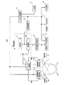
本実施形態における超音波診断装置の構成につき図1乃至図6を用いて説明する。尚、図1は、超音波診断装置の全体構成を示すブロック図であり、図3及び図4は、この超音波診断装置が備える送受信部及び受信信号処理部の具体的な構成を示すブロック図である。
(Device configuration)
The configuration of the ultrasonic diagnostic apparatus according to the present embodiment will be described with reference to FIGS. FIG. 1 is a block diagram showing an overall configuration of the ultrasonic diagnostic apparatus, and FIGS. 3 and 4 are block diagrams showing specific configurations of a transmission / reception unit and a received signal processing unit included in the ultrasonic diagnostic apparatus. It is.
尚、以下の実施形態では、説明を簡単にするために第1の超音波プローブ及び第2の超音波プローブの各々が備えるN個の振動素子の中から選択したNa個及びNb個の振動素子を送受信用振動素子(送信用振動素子及び受信用振動素子)として用い、これらの送受信用振動素子と送受信部が備えるNoチャンネルの送信部及び受信部の中から選択したNaチャンネル及びNbチャンネルの送信部及び受信部とを接続することによって被険体に対する超音波送受信を同時に行う場合について述べるが、送信用振動素子及び受信用振動素子の数や選択方法はこれらに限定されない。 In the following embodiments, Na and Nb vibrating elements selected from N vibrating elements included in each of the first ultrasonic probe and the second ultrasonic probe for the sake of simplicity. Is used as a transmission / reception vibration element (transmission vibration element and reception vibration element), and transmission of Na channel and Nb channel selected from these transmission / reception vibration elements and the No channel transmission unit and reception unit included in the transmission / reception unit Although the case where ultrasonic transmission / reception with respect to a to-be-accompanied body is simultaneously performed by connecting a part and a receiving part is described, the number and selection method of the transmitting vibration element and the receiving vibration element are not limited thereto.
又、第1の超音波プローブによって得られた第1のBモードデータ及び第2の超音波プローブによって得られた第2のBモードデータに基づいて第1の診断用画像データを生成し、第1の超音波プローブによって得られたBモードデータ及び第2の超音波プローブによって得られたカラードプラデータに基づいて第2の診断用画像データを生成する場合について述べるが、収集される診断用画像データは第1の診断用画像データあるいは第2の診断用画像データの何れかであってもよく、又、他の超音波データに基づいた診断用画像データであっても構わない。 The first diagnostic image data is generated based on the first B-mode data obtained by the first ultrasonic probe and the second B-mode data obtained by the second ultrasonic probe, The case where the second diagnostic image data is generated based on the B-mode data obtained by the first ultrasonic probe and the color Doppler data obtained by the second ultrasonic probe will be described. The data may be either first diagnostic image data or second diagnostic image data, or may be diagnostic image data based on other ultrasonic data.
図1に示す本実施形態の超音波診断装置100は、被検体の診断対象部位に対して超音波パルス(送信超音波)を送信し、この送信によって得られた超音波反射波(受信超音波)を電気信号(受信信号)に変換するN個の振動素子を備えた超音波プローブ2a(第1の超音波プローブ)及び超音波プローブ2b(第2の超音波プローブ)と、超音波プローブ2a及び超音波プローブ2bの各々が備えるN個の振動素子の中から選択されたNa個及びNb個の送受信用振動素子と、後述の送受信部4が備えるNoチャンネルの送信部41及び受信部42の中から選択された上述の送受信用振動素子に対応する送信部及び受信部とを接続するチャンネル接続部3と、当該被検体の所定方向に対し超音波パルスを送信するための駆動信号をチャンネル接続部3によって接続された超音波プローブ2a及び超音波プローブ2bの送受信用振動素子へ供給し、チャンネル接続部3を介してこれらの送受信用振動素子から得られたNaチャンネル及びNbチャンネルの受信信号を整相加算する送受信部4と、整相加算後の受信信号を信号処理して超音波データとしてのBモードデータ(第1のBモードデータ及び第2のBモードデータ)やカラードプラデータを生成する受信信号処理部5と、受信信号処理部5において生成された超音波データを用いて画像データ(第1のBモード画像データ、第2のBモードデータ及びカラードプラ画像データ)を生成する画像データ生成部6を備えている。
The ultrasonic
更に、超音波診断装置100は、超音波プローブ2aの受信信号に基づいて生成された第1のBモード画像データと超音波プローブ2bの受信信号に基づいて生成された第2のBモード画像データとを所定フォーマットで合成することにより第1の診断用画像データを生成し、上述した第1のBモード画像データと超音波プローブ2bの受信信号に基づいて生成されたカラードプラ画像データとを合成することにより第2の診断用画像データを生成する画像データ合成部7と、生成された第1の診断用画像データ及び第2の診断用画像データを表示する表示部8と、被検体情報の入力、超音波送受信条件の設定、画像データ生成条件及び画像データ表示条件の設定、検査モードの選択、各種指示信号の入力等を行う入力部9と、送受信方向の制御、送受信用振動素子に対応した送信部及び受信部の駆動制御、レートパルス間隔の制御等を行う走査制御部10と、超音波プローブ2aの位置情報を検出する位置情報検出部11a(第1の位置情報検出部)及び超音波プローブ2bの位置情報を検出する位置情報検出部11b(第2の位置情報検出部)と、上述の各ユニットを統括的に制御するシステム制御部12とを備えている。
Furthermore, the ultrasonic
被検体の周囲に配置された超音波プローブ2a及び超音波プローブ2bの各々はN個の図示しない振動素子をその先端部に有し、この先端部を被険体表面に接触させた状態で被険体内に対する超音波送受信を行う。そして、超音波プローブ2a及び超音波プローブ2bの各々が備えるN個の振動素子の中から選択されたNa個及びNb個の送受信用振動素子は、多芯ケーブルを介してチャンネル接続部3に接続されている。
Each of the
これらの振動素子は電気音響変換素子であり、送信時には電気パルス(駆動信号)を超音波パルス(送信超音波)に変換し、又、受信時には超音波反射波(受信超音波)を電気的な受信信号に変換する機能を有している。尚、超音波プローブ2a及び超音波プローブ2bには、セクタ走査対応、リニア走査対応、コンベックス走査対応等があり、操作者は、これらの超音波プローブを診断部位や診断目的に応じて任意に選択することが可能であるが、本実施形態では、N個の振動素子が1次元配列されたセクタ走査用の超音波プローブ2a及び超音波プローブ2bを用いた場合について述べる。尚、上述の超音波プローブ2a及び超音波プローブ2bは、超音波診断装置100に対し独立して設けられていてもよい。
These vibration elements are electroacoustic transducers, which convert electrical pulses (driving signals) into ultrasonic pulses (transmitted ultrasonic waves) during transmission, and electrically transmit ultrasonic reflected waves (received ultrasonic waves) during reception. It has a function of converting to a received signal. The
次に、チャンネル接続部3の機能につき図2の模式図を用いて説明する。
Next, the function of the
図2に示すチャンネル接続部3は、超音波プローブ2aが備えるN個の振動素子の中から選択されたNa個の送受信用振動素子21a−1乃至21a−Naと、送受信部4が備えるNoチャンネルの送信部41及び受信部42の中から選択された上述の送受信用振動素子21a−1乃至21a−Naに対応する図示しない送信部41a−1乃至41a−Na及び受信部42a−1乃至42a−Naとを接続する接続端子Swa−1乃至Swa−Naを有し、同様にして、超音波プローブ2bが備えるN個の振動素子の中から選択されたNb個の送受信用振動素子21b−1乃至21b−Nbと、上述の送信部41及び受信部42の中から選択された送受信用振動素子21b−1乃至21b−Nbに対応する図示しない送信部41b−1乃至41b−Nb及び受信部42b−1乃至42b−Nbとを接続する接続端子Swb−1乃至Swb−Nbを有している。
The
即ち、送受信部4の送信部41a−1乃至41a−Naが備える駆動回路413a−1乃至413a−Naが発生した駆動信号は、チャンネル接続部3の接続端子Swa−1乃至Swa−Naを介して超音波プローブ2aが備える送受信用振動素子21a−1乃至21a−Naへ供給され、これらの送受信用振動素子によって得られた受信信号は、上述の接続端子Swa−1乃至Swa−Naを介して送受信部4の受信部42a−1乃至42a−Naが備えるプリアンプ421a−1乃至413a−Naへ供給される。
That is, the drive signals generated by the
同様にして、送受信部4の送信部41b−1乃至41b−Nbが備える駆動回路413b−1乃至413b−Nbが発生した駆動信号は、チャンネル接続部3の接続端子Swb−1乃至Swb−Nbを介して超音波プローブ2bが備える送受信用振動素子21b−1乃至21b−Nbへ供給され、これらの送受信用振動素子によって得られた受信信号は、上述の接続端子Swb−1乃至Swb−Nbを介して送受信部4の受信部42b−1乃至42b−Nbが備えるプリアンプ421b−1乃至421b−Nbへ供給される。
Similarly, the drive signals generated by the
尚、上述したチャンネル接続部3の機能は、専用のプローブコネクタを用いて超音波プローブ2a及び超音波プローブ2bと送受信部4を接続することにより自動的に得ることが可能である。
The function of the
次に、図1の送受信部4は、図3に示すように、上述のチャンネル接続部3によって接続された超音波プローブ2aの送受信用振動素子21a−1乃至21a−Naに対して駆動信号を供給する送信部41a及び超音波プローブ2bの送受信用振動素子21b−1乃至21b−Nbに対して駆動信号を供給する送信部41bと、上述した超音波プローブ2aの送受信用振動素子21a−1乃至21a−Naからチャンネル接続部3の接続端子Swa−1乃至Swa−Naを介して供給されたNaチャンネルの受信信号を整相加算する受信部42a及び超音波プローブ2bの送受信用振動素子21b−1乃至21b−Nbからチャンネル接続部3の接続端子Swb−1乃至Swb−Nbを介して供給されるNbチャンネルの受信信号を整相加算する受信部42bを備えている。
Next, as shown in FIG. 3, the transmission /
送信部41a(41b)は、レートパルス発生器411a(411b)、送信遅延回路412a(412b)及び駆動回路413a(413b)を備え、レートパルス発生器411a(411b)は、走査制御部10から供給されるレート間隔制御信号に基づいて送信超音波の放射間隔を決定するレートパルスを生成し送信遅延回路412a(412b)へ供給する。
The
送信遅延回路412a(412b)は、超音波プローブ2a(2b)が備えるNa個(Nb個)の送受信用振動素子と同数の独立な遅延回路から構成され、走査制御部10から供給される遅延時間制御信号に基づいて送信超音波を所定の深さに集束するための集束用遅延時間と所定の方向θp(φq)へ送信するための偏向用遅延時間を上記レートパルスに与えて駆動回路413a(413b)へ供給する。そして、駆動回路413a(413b)は、上述のレートパルスに同期した駆動信号を生成し、超音波プローブ2a(2b)の送受信用振動素子21a−1乃至21a−Na(21b−1乃至21b−Nb)へ供給することによって被検体内へ送信超音波を放射する。
The
一方、受信部42a(42b)は、超音波プローブ2a(2b)の送受信用振動素子21a−1乃至21a−Na(21b−1乃至21b−Nb)に対応するNa(Nb)チャンネルのプリアンプ421a(421b)、A/D変換器422a(422b)及び受信遅延回路423a(423b)と加算器424a(424b)を備えている。そして、超音波プローブ2a(2b)の送受信用振動素子21a−1乃至21a−Na(21b−1乃至21b−Nb)から供給されるNa(Nb)チャンネルの受信信号は、プリアンプ421a(421b)において生体組織内の伝播距離に依存した減衰量が補正された後、A/D変換器422a(422b)においてデジタル信号に変換され受信遅延回路423a(423b)へ送られる。
On the other hand, the receiving
受信遅延回路423a(423b)は、所定の深さからの受信超音波を集束するための集束用遅延時間と、所定の方向θpに対して強い受信指向性を設定するための偏向用遅延時間をA/D変換器422a(422b)から出力されたNa(Nb)チャンネルの受信信号に与え、加算器424a(424b)は、受信遅延回路423a(423b)から出力された受信信号を加算合成する。即ち、受信遅延回路423aと加算器424aにより、超音波プローブ2aの送受信用振動素子21a−1乃至21a−Naから供給されたNaチャンネルの受信信号及び超音波プローブ2bの送受信用振動素子21b−1乃至21b−Nbから供給されたNbチャンネルの受信信号は夫々整相加算される。
The
尚、受信遅延回路423a(423b)及び加算器424a(424b)は、後述する走査制御部10の遅延時間制御により複数方向からの受信超音波を同時に受信する、所謂、並列同時受信法を行うことも可能であり、この並列同時受信法の適用により所定撮影領域の超音波走査に要する時間は更に短縮される。
Note that the
次に、図4に示す受信信号処理部5は、Bモード検査において受信部42aの加算器424aから出力された整相加算後の受信信号を処理して第1のBモードデータを生成するBモードデータ生成部51a及び受信部42bの加算器424bから出力された整相加算後の受信信号を処理して第2のBモードデータを生成するBモードデータ生成部51bと、カラードプラモード検査において上述の加算器424bから出力された整相加算後の受信信号を直交位相検波することによりこれらの受信信号に混在しているドプラ信号を検出するドプラ信号検出部52と、検出されたドプラ信号を処理してカラードプラデータを生成するカラードプラデータ生成部53とを有している。
Next, the reception
Bモードデータ生成部51a(51b)は、超音波プローブ2a(2b)の送受信振動素子21a−1乃至21a−Na(21b−1乃至21b−Na)によって受信されチャンネル接続部3の接続端子SWa−1乃至SWa−Na(SWb−1乃至SWb−Na)や受信部42a(42b)のプリアンプ421a−1乃至421a−Na(421b−1乃至421b−Nb)等を介して供給された整相加算後の受信信号を包絡線検波する包絡線検波器511a(511b)と、包絡線検波された受信信号の振幅を対数変換して第1のBモードデータ(第2のBモードデータ)を生成する対数変換器512a(512b)を有している。
The B-mode data generation unit 51a (51b) is received by the transmission /
ドプラ信号検出部52は、π/2移相器521、ミキサ522−1及び522−2、LPF(低域通過フィルタ)523−1及び523−2を有し、上述の受信部42aあるいは受信部42bから供給された整相加算後の受信信号を直交位相検波して実成分(I成分)と虚成分(Q成分)とからなる複素型のドプラ信号を検出する。
The Doppler signal detection unit 52 includes a π / 2
カラードプラデータ生成部53は、ドプラ信号記憶回路531、MTIフィルタ532及び自己相関演算器533を有し、同一方向に対する複数回の超音波送受信においてドプラ信号検出部52のLPF523−1及びLPF523−2から出力されたドプラ信号の実成分と虚成分は、ドプラ信号記憶回路531に一旦保存される。
The color Doppler data generation unit 53 includes a Doppler
低域成分除去用のデジタルフィルタであるMTIフィルタ532は、当該被検体の同一部位にて収集された時系列的なドプラ信号をドプラ信号記憶回路531から順次読み出す。そして、これらのドプラ信号に含まれている血流に起因した成分(血流成分)を抽出し、臓器の呼吸性移動や拍動性移動等に起因した成分(クラッタ成分)を除去する。次いで、自己相関演算器533は、MTIフィルタ532によって抽出されたドプラ信号の血流成分に対して自己相関演算を行い、血流の平均流速値や血流速度の乱れを示す速度分散値、更には、血流成分の大きさを示すパワー値等をカラードプラデータとして算出する。
The
図1へ戻って、画像データ生成部6は、例えば、超音波データ記憶部と演算処理部の機能を有したDSC(digital Scan Converter)あるいはDSP(Digital Signal Processor)等によって構成され、受信信号処理部5において生成された第1のBモードデータ、第2のBモードデータ及びカラードプラデータに基づいて画像データを生成する図示しないBモード画像データ生成部及びカラードプラ画像データ生成部を有している。
Returning to FIG. 1, the image
Bモード画像データ生成部が備える超音波データ記憶部には、受信信号処理部5のBモードデータ生成部51a及びBモードデータ生成部51bから送受信方向単位で時系列的に供給される第1のBモードデータ及び第2のBモードデータが送受信方向に対応させて順次保存される。そして、演算処理部は、超音波データ記憶部に保存された上述のBモードデータに対してフィルタリング処理等の演算処理を行うことにより超音波プローブ2aに対応する第1のBモード画像データ及び超音波プローブ2bに対応する第2のBモード画像データを生成する。
The ultrasonic data storage unit included in the B-mode image data generation unit is supplied with a first time series in units of transmission / reception directions from the B-mode data generation unit 51a and the B-mode data generation unit 51b of the reception
一方、カラードプラ画像データ生成部は、受信信号処理部5のカラードプラデータ生成部53から供給されたカラードプラデータに基づいてカラードプラ画像データを生成する。例えば、血流の平均流速値に対応した明度情報と速度分散値に対応した色相情報を各々の画素値として設定することにより平均流速値と速度分散値の同時観測が可能なカラードプラ画像データを生成する。
On the other hand, the color Doppler image data generation unit generates color Doppler image data based on the color Doppler data supplied from the color Doppler data generation unit 53 of the reception
次に、画像データ合成部7は、超音波プローブ2aに装着された位置情報検出部11a(第1の位置情報検出部)及び超音波プローブ2bに装着された位置情報検出部11b(第2の位置情報検出部)において検出され、システム制御部12を介して供給される超音波プローブ2a及び超音波プローブ2bの位置情報(例えば、各々のプローブが備える送受信用振動素子の配列中心位置及び配列方向)を受信する。次いで、画像データ生成部6のBモード画像データ生成部から供給される超音波プローブ2aに対応した第1のBモード画像データと超音波プローブ2bに対応した第2の画像データとを上述した超音波プローブ2a及び超音波プローブ2bの位置情報に基づいて合成することにより第1の診断用画像データを生成する。
Next, the image
又、画像データ合成部7は、例えば、画像データ生成部6のBモード画像データ生成部から供給される超音波プローブ2aに対応した第1のBモード画像データとカラードプラ画像データ生成部から供給される超音波プローブ2bに対応したカラードプラ画像データとを上述した超音波プローブ2a及び超音波プローブ2bの位置情報に基づいて合成することにより第2の診断用画像データを生成する。
The image
尚、画像データ合成部7において生成される第1の診断用画像データ及び第2の診断用画像データの具体例については後述する。
A specific example of the first diagnostic image data and the second diagnostic image data generated by the image
表示部8は、図示しない表示データ生成部、データ変換部及びモニタを備えている。表示データ生成部は、画像データ合成部7において生成された第1の診断用画像データあるいは第2の診断用画像データに対し入力部9からシステム制御部12を介して供給される被検体情報等の付帯情報を付加して表示データを生成する。そして、データ変換部は、上述の表示データに対してD/A変換やテレビフォーマット変換等の変換処理を行ってモニタに表示する。
The
入力部9は、表示パネルやキーボード、各種スイッチ、選択ボタン、マウス、トラックボール等の入力デバイスを備えたインターラクティブなインターフェースであり、被検体情報の入力、超音波送受信条件の設定、超音波データ生成条件の設定、画像データ生成条件及び画像データ表示条件の設定、検査モード(Bモード及びカラードプラモード)の選択、走査範囲及び送受信方向数(走査線数)Mの設定、更には、各種指示信号の入力等が上述の表示パネルや入力デバイスを用いて行われる。 The input unit 9 is an interactive interface including input devices such as a display panel, a keyboard, various switches, selection buttons, a mouse, and a trackball. The input unit 9 inputs subject information, sets ultrasonic transmission / reception conditions, and generates ultrasonic data. Setting of conditions, setting of image data generation conditions and image data display conditions, selection of inspection mode (B mode and color Doppler mode), setting of scanning range and number of transmission / reception directions (number of scanning lines) M, and various instruction signals Are input using the above-described display panel and input device.
走査制御部10は、図示しない送受信方向制御部とレート間隔制御部を有している。
The
送受信方向制御部は、入力部9からシステム制御部12を介して供給される超音波送受信条件の走査範囲等に基づいて送信部41a(41b)の送信遅延回路412a(412b)及び受信部42a(42b)の受信遅延回路423a(423b)における遅延時間を制御することにより、同一時刻における超音波プローブ2aの送受信方向と超音波プローブ2bの送受信方向が接近しないように各々の送受信方向を設定する。
The transmission / reception direction control unit is configured to transmit the
図5は、例えば、超音波プローブ2aの走査領域Haと超音波プローブ2bの走査領域Hbが同一平面上に設定された場合の各々の超音波プローブにおける送受信方向(図5(a))とこのとき画像データ合成部7において生成される診断用画像データ(図5(b))の具体例を示したものである。
FIG. 5 shows, for example, the transmission / reception directions (FIG. 5A) of each ultrasonic probe when the scanning area Ha of the
図5(a)の矢印θ1、θ2、θ3、・・・は、時刻t1、t2、t3、・・・(t1<t2<t3・・)において走査領域Haの左端部から右端部方向へ向かって移動する超音波プローブ2aの送受信方向を示しており、矢印φ1、φ2、φ3、・・・は、同一時刻t1、t2、t3、・・・において走査領域Hbの中央部から右端部方向へ向かって移動する超音波プローブ2bの送受信方向を示している。
The arrows θ1, θ2, θ3,... In FIG. 5A point from the left end to the right end of the scanning area Ha at times t1, t2, t3,... (T1 <t2 <t3...). The arrows φ1, φ2, φ3,... Indicate the direction from the center of the scanning region Hb toward the right end at the same time t1, t2, t3,. The transmission / reception direction of the
このように、同一時刻における超音波プローブ2aの送受信方向と超音波プローブ2bの送受信方向を離すことにより、超音波プローブ間の混信(例えば、超音波プローブ2aから放射された送信超音波の超音波プローブ2bによる受信)を低減することが可能となる。
Thus, by separating the transmission / reception direction of the
一方、図5(b)は、上述のように同一平面上の同一時刻における送受信方向を接近させない状態で超音波プローブ2a及び超音波プローブ2bによって得られた受信信号に基づいて画像データ合成部7が生成した第1の診断用画像データあるいは第2の診断用画像データを示している。この場合、第1の診断用画像データは、走査領域Haに対する超音波プローブ2aの超音波送受信によって得られた第1のBモード画像データGaと、走査領域Hbに対する超音波プローブ2bの超音波送受信によって得られた第2のBモード画像データGbを各々の超音波プローブの位置情報に基づいて合成することにより得られ、同様にして、第2の診断用画像データは、走査領域Haに対する超音波プローブ2aの超音波送受信によって得られた第1のBモード画像データGaと、走査領域Hbに対する超音波プローブ2bの超音波送受信によって得られたカラードプラ画像データGbを合成することにより得られる。
On the other hand, FIG. 5B shows an image
一方、上述した走査制御部10のレート間隔制御部は、例えば、第1の診断用画像データのように、同一検査モードの画像データを合成することによって診断用画像データが生成される場合、同一平面上に設定された超音波プローブ2aの走査領域Haと超音波プローブ2bの走査領域Hbが重複しないようにレートパルスの間隔(即ち、受信信号の受信期間)を制御する。
On the other hand, the rate interval control unit of the
図6は、各々の走査領域が重ならないように設定された超音波プローブ2aの走査領域Faと超音波プローブ2bの走査領域Fbを示したものであり、走査領域内の矢印の方向は、図5の場合と同様に超音波の送受信方向を示し、矢印の長さは、受信信号の受信期間に対応している。
FIG. 6 shows the scanning region Fa of the
この場合、上述のレート間隔制御部は、送信部41aのレートパルス発生器411aを制御し、送受信方向制御部は、送信部41aの送信遅延回路412a及び受信部42aの受信遅延回路423aを制御する。そして、例えば、超音波プローブ2aを用いた送受信方向θ1に対する超音波送受信において斜線で示した境界領域Boからの受信超音波が受信されたならばθ2に対する超音波送受信へ切り替えるための新たなレートパルスの発生と遅延時間の制御を行い、送受信方向θ2、θ3、・・・に対する超音波送受信において境界領域Boからの受信超音波が受信されたならばθ3、θ4、・・・に対する超音波送受信へ切り替えるためのレートパルスの発生と遅延時間の制御を順次行う。
In this case, the rate interval control unit described above controls the
同様にして、レート間隔制御部は、送信部41bのレートパルス発生器411bを制御し、送受信方向制御部は、送信部41bの送信遅延回路412b及び受信部42bの受信遅延回路423bを制御する。そして、例えば、超音波プローブ2bを用いた送受信方向φ1に対する超音波送受信において境界領域Boからの受信超音波が受信されたならばφ2に対する超音波送受信へ切り替えるためのレートパルスの発生と遅延時間の制御を行い、送受信方向φ2、φ3、・・・に対する超音波送受信において境界領域Boからの受信超音波が受信されたならばφ3、φ4、・・・に対する超音波送受信へ切り替えるためのレートパルスの発生と遅延時間の制御を行う。
Similarly, the rate interval control unit controls the
このように、レートパルスの時間間隔を制御して同一領域からの受信信号を超音波プローブ2a及び超音波プローブ2bを用いて受信する期間を除くことにより、診断用画像データのフレームレートを更に短縮することが可能となる。
As described above, the frame rate of the diagnostic image data is further reduced by controlling the rate pulse time interval and excluding the period in which the reception signals from the same region are received using the
再び図1へ戻って、超音波プローブ2aに装着された位置情報検出部11a及び超音波プローブ2bに装着された位置情報検出部11bの各々は、超音波プローブ2a及び超音波プローブ2bの位置情報としてこれらの超音波プローブが備える送受信用振動素子の配列中心位置や配列方向等を検出する機能を有している。
Returning to FIG. 1 again, each of the position information detection unit 11a attached to the
超音波プローブの位置情報検出を目的とした各種の方法が提案されているが、検出精度、コスト及び大きさ等を考慮した場合、超音波センサあるいは磁気センサを用いた方法が好適である。例えば、磁気センサを有した位置情報検出部11a(11b)は、特開2000−5168号公報等に記載されているように磁気を発生するトランスミッタ(磁気発生部)と、この磁気を検出する複数の磁気センサを有したレシーバと、検出された磁気に基づく電気信号(検出信号)を処理して超音波プローブ2a及び超音波プローブ2bの位置情報を算出する位置情報算出部(何れも図示せず)を備えている。
Various methods for detecting the position information of the ultrasonic probe have been proposed. In consideration of detection accuracy, cost, size, and the like, a method using an ultrasonic sensor or a magnetic sensor is preferable. For example, the position information detector 11a (11b) having a magnetic sensor includes a transmitter (magnet generator) that generates magnetism and a plurality of magnets that detect the magnetism as described in Japanese Patent Application Laid-Open No. 2000-5168. And a position information calculation unit for processing the electrical signal (detection signal) based on the detected magnetism and calculating the position information of the
磁気センサを有したレシーバは、通常、超音波プローブ2a(2b)の表面に装着され、トランスミッタは、超音波プローブ2a(2b)の近傍に設置される。そして、位置情報算出部は、磁気によって計測された複数からなる磁気センサの各々とトランスミッタとの距離に基づいて超音波プローブ2a(2b)の位置情報を算出する。
The receiver having the magnetic sensor is usually mounted on the surface of the
システム制御部12は、図示しないCPUと入力情報記憶部を備え、入力情報記憶部には、入力部9において入力/設定/選択された上述の被検体情報や超音波送受信条件等が保存される。そして、CPUは、これらの入力情報/設定情報/選択情報に基づいて超音波診断装置100の各ユニットを統括的に制御することにより当該超音波診断に好適な診断用画像データの生成と表示を実行させる。
The
(診断用画像データの生成/表示手順)
次に、本実施形態における診断用画像データの生成/表示手順につき図7のフローチャートに沿って説明する。但し、ここでは、超音波プローブ2a(第1の超音波プローブ)を用いて得られた第1のBモードデータと超音波プローブ2b(第2の超音波プローブ)を用いて得られた第2のBモードデータとの合成によって第1の診断用画像データを生成する場合について述べるが、Bモード画像データとカラードプラ画像データとの合成による第2の診断用画像データも同様の手順によって生成することができる。
(Procedure for generating / displaying diagnostic image data)
Next, a procedure for generating / displaying diagnostic image data in the present embodiment will be described with reference to the flowchart of FIG. However, here, the second B obtained by using the first B-mode data obtained by using the
当該被検体に対する超音波検査に先立ち、超音波診断装置100を操作する医療従事者(以下、操作者と呼ぶ。)は、入力部9において被検体情報を入力した後、超音波送受信条件の設定、超音波データ生成条件の設定、画像データ生成条件及び画像データ表示条件の設定、走査範囲及び送受信方向数(M)の設定等を行い、更に、検査モードとしてBモードを選択する(図7のステップS1)。
Prior to the ultrasound examination of the subject, a medical worker (hereinafter referred to as an operator) who operates the ultrasound
上述の初期設定を終了したならば、操作者は、被検体の体表面に超音波プローブ2a及び音波プローブ2bの先端部を配置し(図7のステップS2)、入力部9において超音波検査開始指示を入力する(図7のステップS3)。
When the above initial setting is completed, the operator places the distal end portions of the
そして、この指示信号がシステム制御部12へ供給されることにより、超音波プローブ2a及び超音波プローブ2bを用いた診断用画像データの収集が開始される。
Then, by supplying this instruction signal to the
診断用画像データの収集に際し、システム制御部12から上述の指示信号を受信した走査制御部10は、この指示信号と共に超音波送受信条件としてシステム制御部12から供給された走査範囲や送受信方向数Mの情報と位置情報検出部11aから供給された超音波プローブ2aの位置情報及び位置情報検出部11bから供給された超音波プローブ2bの位置情報を受信する。そして、これらの情報に基づいて生成した送受信方向制御信号を送信部41a(41b)の送信遅延回路412a(412b)及び受信部42a(42b)の受信遅延回路423a(423b)へ供給し、上述の情報に基づいて生成したレート間隔制御信号を送信部41a(41b)のレートパルス発生器411a(411b)へ供給する。
Upon collecting diagnostic image data, the
レートパルス発生器411aは、走査制御部10から供給されたレート間隔制御信号に従って所定の時間間隔を有したレートパルスを生成し送信遅延回路412aへ供給する。
The
一方、送信遅延回路412aは、走査制御部10から供給された送受信方向制御信号に基づき、送信超音波を送受信方向θ1へ送信するための偏向用遅延時間と所定の距離(深さ)に集束するための集束用遅延時間を上述のレートパルスに与え、このレートパルスを駆動回路413a−1乃至413a−Naへ供給する。そして、駆動回路413a−1乃至413a−Naは、送信遅延回路412aが出力する上述のレートパルスに同期した駆動信号を生成し、チャンネル接続部3を介して超音波プローブ2aの送受信用振動素子21a−1乃至21a−Naへ供給することによって被検体内のθ1方向へ送信超音波を放射する。
On the other hand, the
このとき放射された送信超音波の一部は、音響インピーダンスの異なる組織等の境界において反射し、上述の送受信用振動素子21a−1乃至21a−Naによって電気的な受信信号に変換される。そして、チャンネル接続部3を介して受信部42aへ供給されたNaチャンネルの受信信号は、プリアンプ421aにおいて増幅され、A/D変換器422aにおいてデジタル信号に変換された後、受信遅延回路423aにおいて所定の深さからの受信超音波を集束するための集束用遅延時間と送受信方向θ1からの受信超音波に対し強い受信指向性を設定するための偏向用遅延時間が与えられ、加算器424aにて加算合成(整相加算)される(図7のステップS4a)。
A part of the transmitted ultrasonic wave radiated at this time is reflected at a boundary between tissues having different acoustic impedances and converted into an electrical reception signal by the transmitting / receiving
そして、整相加算後の受信信号が供給された受信信号処理部5のBモードデータ生成部51aは、この受信信号に対して包絡線検波と対数変換を行って第1のBモードデータを生成し、画像データ生成部6の超音波データ記憶部に保存する(図7のステップS5a)。
The B-mode data generation unit 51a of the reception
一方、上述のステップS4a及びステップS5aと並行して超音波プローブ2b、送信部41b及び受信部42bを用いた当該被険体内のφ1方向に対する超音波送受信とBモードデータ生成部51bを用いた第2のBモードデータの生成/保存が後述のステップS4b及びステップS5bにおいて行われる。
On the other hand, in parallel with the above-described step S4a and step S5a, ultrasonic transmission / reception in the φ1 direction in the subject using the
即ち、送信部41bのレートパルス発生器411bは、走査制御部10から供給されるレート間隔制御信号に従って生成したレートパルスを送信遅延回路412bへ供給し、送信遅延回路412bは、走査制御部10から供給された送受信方向制御信号に基づいて設定した偏向用遅延時間及び集束用遅延時間を上述のレートパルスに与えて駆動回路413b−1乃至413b−Nbへ供給する。次いで、駆動回路413b−1乃至413b−Nbは、これらのレートパルスに同期させて生成した駆動信号を超音波プローブ2bの送受信用振動素子21b−1乃至21b−Nbへ供給することによって被検体内のφ1方向へ送信超音波を放射する。
That is, the
そして、音響インピーダンスの異なる被険体組織の境界等において反射した送信超音波の一部は、送受信用振動素子21b−1乃至21b−Nbによって受信信号に変換され、受信部42bのプリアンプ421b及びA/D変換器422bを介して受信遅延回路423bへ供給される。一方、受信遅延回路423bは、供給されたNbチャンネルの受信信号に対して所定の集束用遅延時間及び偏向用遅延時間を与え、加算器424bは、これらの遅延時間が与えられたNbチャンネル受信信号を加算合成(整相加算)する(図7のステップS4b)。
Then, a part of the transmission ultrasonic wave reflected at the boundary of the to-be-affected body tissue having different acoustic impedance is converted into a reception signal by the transmission /
次いで、整相加算後の受信信号が供給された受信信号処理部5のBモードデータ生成部51bは、この受信信号に対して包絡線検波と対数変換を行って第2のBモードデータを生成し、画像データ生成部6の超音波データ記憶部に保存する(図7のステップS5b)。
Next, the B-mode data generation unit 51b of the reception
上述したステップS4a及びステップS5aとステップS4b及びステップS5bの手順により、送受信方向θ1における第1のBモードデータ及び送受信方向φ1における第2のBモードデータの生成と保存が終了したならば、走査制御部10は、レートパルス発生器411a(411b)におけるレート間隔、送信遅延回路412a(412b)及び受信遅延回路423a(423b)における遅延時間等を制御して送受信方向θ2乃至θM及び送受信方向φ2乃至φMに対する超音波送受信を上述のステップS4a及びステップS4bと同様の手順によって行い、更に、整相加算後の受信信号を用いたBモードデータの生成と保存をステップS5a及びステップS5bと同様の手順によって行う。
If the generation and storage of the first B-mode data in the transmission / reception direction θ1 and the second B-mode data in the transmission / reception direction φ1 are completed by the procedure of step S4a, step S5a, step S4b, and step S5b described above, scanning control is performed. The
そして、超音波プローブ2aの走査領域に対して設定された送受信方向θ1乃至θMにおける第1のBモードデータの生成/保存及び超音波プローブ2bの走査領域に対して設定された送受信方向φ1乃至φMにおける第2のBモードデータの生成/保存が終了したならば、画像データ生成部6のBモード画像データ生成部は、自己の超音波データ記憶部から読み出した第1のBモードデータ及び第2のBモードデータに対してフィルタリング処理等の演算処理を行うことにより超音波プローブ2aに対応した第1のBモード画像データ及び超音波プローブ2bに対応した第2のBモード画像データを生成する(図7のステップS6)。
Then, the generation / storage of the first B mode data in the transmission / reception directions θ1 to θM set for the scanning region of the
次いで、画像データ合成部7は、超音波プローブ2aに装着された位置情報検出部11a(第1の位置情報検出部)及び超音波プローブ2bに装着された位置情報検出部11b(第2の位置情報検出部)において検出され、システム制御部12を介して供給された超音波プローブ2a及び超音波プローブ2bの位置情報を受信する。そして、上述のBモード画像データ生成部から供給された第1のBモード画像データ及び第2のBモード画像データを超音波プローブ2a及び超音波プローブ2bの位置情報に基づいて合成することにより第1の診断用画像データを生成し、得られた第1の診断用画像データを表示部8のモニタに表示する(図7のステップS7)。
Next, the image
以上述べた実施形態によれば、超音波検査の走査領域に対する超音波送受信を被険体の周囲に配置された2つの超音波プローブを用いて同時に行い、このとき各々の超音波プローブによって収集された画像データを合成することにより、超音波が被検体の組織内を伝播する際の吸収に起因した感度劣化やこの伝播を妨げる骨や肺等の音響的障害物に起因した局所的な音響陰影等が改善された良質な診断用画像データを短時間で収集することができる。 According to the embodiment described above, ultrasonic transmission / reception with respect to the scanning region of the ultrasonic inspection is performed simultaneously using two ultrasonic probes arranged around the to-be-tested body, and at this time, collected by each ultrasonic probe. By synthesizing the acquired image data, sensitivity degradation due to absorption of ultrasonic waves through the tissue of the subject and local acoustic shadows caused by acoustic obstacles such as bones and lungs that interfere with this propagation It is possible to collect high-quality diagnostic image data improved in a short time.
又、レートパルスの時間間隔を制御することによって同一領域からの受信信号を、2つの超音波プローブを用いて受信する期間を除くことにより、診断用画像データのフレームレートを更に短縮することが可能となる。 In addition, the frame rate of diagnostic image data can be further reduced by controlling the rate pulse time interval to eliminate the period during which received signals from the same area are received using two ultrasonic probes. It becomes.
更に、送受信部が備える複数チャンネルの送信部及び受信部と上述した超音波プローブの各々が備える送受信用振動素子とをチャンネル接続部によって接続することにより、当該被険体に対する複数方向からの超音波送受信を同時に行うことができる。特に、2次元アレイ超音波プローブとの接続が可能な近年の超音波診断装置のように送受信部が極めて多くのチャンネル数を有している場合には、複数の超音波プローブによる同時送受信は容易に実現可能となる。 Furthermore, by connecting the transmitting and receiving units of a plurality of channels included in the transmitting / receiving unit and the transmitting / receiving vibration element included in each of the above-described ultrasonic probes by the channel connecting unit, ultrasonic waves from a plurality of directions with respect to the subject Transmission and reception can be performed simultaneously. In particular, simultaneous transmission / reception with a plurality of ultrasonic probes is easy when the transmission / reception unit has an extremely large number of channels as in a recent ultrasonic diagnostic apparatus that can be connected to a two-dimensional array ultrasonic probe. It becomes feasible.
以上、本開示の実施形態について述べてきたが、本開示は、上述の実施形態に限定されるものではなく、変形して実施することが可能である。例えば、上述の実施形態では、同一の検査モードにおいて得られた超音波プローブ2aに対応する第1のBモード画像データと超音波プローブ2bに対応する第2のBモード画像データを重畳配置することによって第1の診断用画像データを生成し、異なる検査モードにおいて得られた超音波プローブ2aに対応するBモード画像データと超音波プローブ2bに対応するカラードプラ画像データを重畳配置することにより第2の診断用画像データを生成する場合について述べたが、超音波検査において用いる診断用画像データは、上述した第1の診断用画像データあるいは第2の診断用画像データの何れかであってもよく、他の検査モードの超音波データに基づいて生成された診断用画像データであってもよい。
As mentioned above, although embodiment of this indication has been described, this indication is not limited to the above-mentioned embodiment, and it can change and carry out. For example, in the above-described embodiment, the first B-mode image data corresponding to the
図8は、第1の超音波プローブを用いたBモード検査において収集されるBモード画像データGcと第2の超音波プローブを用いたカラードプラモード検査において収集されるカラードプラ画像データGdとを重畳配置することによって得られた第2の診断用画像データの変形例を示したものである。 FIG. 8 shows B-mode image data Gc collected in the B-mode inspection using the first ultrasonic probe and color Doppler image data Gd collected in the color Doppler mode inspection using the second ultrasonic probe. The modification of the 2nd image data for diagnostics obtained by carrying out superposition is shown.
一般に、血管壁の形状や厚みの計測を目的にしたBモード検査において空間分解能に優れたBモード画像データを得るためには、超音波の送受信方向が血管壁Vxに対して可能な限り垂直になるように超音波プローブの位置や方向を設定する必要があり、血流速度等の計測を目的としたカラードプラモード検査において微小な血流あるいは低流速の血流を感度良く計測するためには、超音波の送受信方向が血管壁Vxあるいは血流方向Voに対して平行になるように超音波プローブの位置や方向を設定することが望ましい。 In general, in order to obtain B-mode image data with excellent spatial resolution in a B-mode examination for measuring the shape and thickness of a blood vessel wall, the transmission / reception direction of ultrasonic waves is as perpendicular as possible to the blood vessel wall Vx. It is necessary to set the position and direction of the ultrasonic probe so that the minute blood flow or low-flow blood flow can be measured with high sensitivity in the color Doppler mode test for measuring blood flow velocity. It is desirable to set the position and direction of the ultrasonic probe so that the ultrasonic wave transmission / reception direction is parallel to the blood vessel wall Vx or the blood flow direction Vo.
しかしながら、従来のような1つの超音波プローブを用いた超音波検査では、上述の相反する2つの条件を同時に満足させることは不可能であるが、図8に示すように、Bモード検査に対応した第1の超音波プローブとカラードプラモード検査に対応した第2の超音波プローブの交叉角度が、例えば、90度となるように配置することにより、血管構造と血流情報を高い精度で観測することが可能な診断用画像データを得ることができる。 However, in the conventional ultrasonic inspection using one ultrasonic probe, it is impossible to satisfy the two conflicting conditions at the same time. However, as shown in FIG. By locating the first ultrasonic probe and the second ultrasonic probe corresponding to the color Doppler mode inspection so that the crossing angle is, for example, 90 degrees, the blood vessel structure and blood flow information can be observed with high accuracy. Diagnostic image data that can be obtained can be obtained.
又、上述の実施形態では、同一平面上に設定された2つの走査領域におけるBモード画像データやカラードプラ画像データを重畳配置することによって第1の診断用画像データ及び第2の診断用画像データを生成する場合について述べたが、2つの走査領域は、同一平面上に存在しなくてもよい。例えば、図9に示すように異なる平面上の2つの走査領域において得られた第1の画像データGe及び第2の画像データGfは、各々の画像データの収集に用いた超音波プローブ2a及び超音波プローブ2bの位置情報に基づいて3次元的に重畳配置される。このとき、重畳領域の手前側にある画像データは半透明あるいは異なる色調の画像データに変換された後、奥側の画像データに対して重畳することにより被険体内の3次元的な情報を把握することができる。
In the above-described embodiment, the first diagnostic image data and the second diagnostic image data are arranged by superimposing B-mode image data and color Doppler image data in two scanning regions set on the same plane. As described above, the two scanning regions do not have to exist on the same plane. For example, as shown in FIG. 9, the first image data Ge and the second image data Gf obtained in two scanning regions on different planes are the
更に、上述の実施形態では、超音波プローブ間の混信を避けるために、同一時刻における第1の超音波プローブの送受信方向と第2の超音波プローブの送受信方向が接近しないように制御する場合について述べたが、送受信振動素子の超音波周波数(共振周波数)が互いに異なる第1の超音波プローブ及び第2の超音波プローブを用いてもよい。この場合、送受信部4や受信信号処理部5では、これらの超音波周波数に対応した駆動信号の生成やフィルタリング処理等が行われる。
Furthermore, in the above-described embodiment, in order to avoid interference between the ultrasonic probes, the transmission / reception direction of the first ultrasonic probe and the transmission / reception direction of the second ultrasonic probe at the same time are controlled so as not to approach each other. As described above, a first ultrasonic probe and a second ultrasonic probe having different ultrasonic frequencies (resonance frequencies) of the transmitting and receiving vibration elements may be used. In this case, the transmission /
一方、上述の実施形態では、2つの超音波プローブ(第1の超音波プローブ及び第2の超音波プローブ)を用いた超音波検査について述べたが、特許文献1のように3つ以上の超音波プローブを用いてもよい。 On the other hand, in the above-described embodiment, the ultrasonic inspection using the two ultrasonic probes (the first ultrasonic probe and the second ultrasonic probe) has been described. An acoustic probe may be used.
又、2つの画像データ(第1の画像データ及び第2の画像データ)を重畳配置することによって診断用画像データを生成する場合について述べたが、第1の画像データ及び第2の画像データを並列配置することによって診断用画像データを生成してもよい。この場合、画像データ合成部は、これらの画像データを並列配置する機能を有する。又、画像データ合成部は、第1の超音波データ及び第2の超音波データを用いて診断用画像データを直接生成しても構わない。 Moreover, although the case where diagnostic image data is generated by superimposing two image data (first image data and second image data) is described, the first image data and the second image data are The diagnostic image data may be generated by arranging them in parallel. In this case, the image data synthesis unit has a function of arranging these image data in parallel. In addition, the image data synthesis unit may directly generate diagnostic image data using the first ultrasonic data and the second ultrasonic data.
更に、上述の実施形態では、第1の超音波プローブ及び第2の超音波プローブを用いて当該被検体の診断対象部位に対する2つの2次元走査を行う場合について述べたが、これに限定されるものではなく、例えば、送受信用振動素子が2次元配列された複数の超音波プローブを用いてボリュームデータを収集し、得られた複数のボリュームデータを合成することによって所望断面における2次元の診断用画像データあるいは3次元の診断用画像データを生成してもよい。 Furthermore, in the above-described embodiment, the case where two two-dimensional scans are performed on the diagnosis target portion of the subject using the first ultrasonic probe and the second ultrasonic probe has been described. However, the present invention is not limited to this. For example, volume data is collected using a plurality of ultrasonic probes in which transmission / reception vibration elements are two-dimensionally arranged, and the obtained plurality of volume data is synthesized to perform two-dimensional diagnosis on a desired cross section. Image data or three-dimensional diagnostic image data may be generated.
又、上述の実施形態では、セクタ走査方式の超音波診断装置100について述べたが、コンベックス走査方式やリニア走査方式等の他の走査方式を適用した超音波診断装置であってもよい。
In the above-described embodiment, the sector scanning ultrasonic
尚、本実施形態の超音波診断装置100に含まれる各ユニットは、CPU、RAM、磁気記憶装置、入力装置、表示装置等で構成されるコンピュータをハードウェアとして用いることでも実現することができる。例えば、超音波診断装置100のシステム制御部12は、上記のコンピュータに搭載されたCPU等のプロセッサに所定の制御プログラムを実行させることにより各種機能を実現することができる。この場合、上述の制御プログラムをコンピュータに予めインストールしてもよく、又、コンピュータ読み取りが可能な記憶媒体への保存あるいはネットワークを介して配布された制御プログラムのコンピュータへのインストールであっても構わない。
Each unit included in the ultrasonic
以上、本発明のいくつかの実施形態を説明したが、これらの実施形態は、例として提示したものであり発明の範囲を限定することは意図していない。これら新規な実施形態は、その他の様々な形態で実施されることが可能であり、発明の要旨を逸脱しない範囲で種々の省略、置き換え、変更を行うことができる。これらの実施形態やその変形例は、発明の範囲や要旨に含まれるとともに、特許請求の範囲に記載された発明とその均等の範囲に含まれる。 Although several embodiments of the present invention have been described above, these embodiments are presented as examples and are not intended to limit the scope of the invention. These novel embodiments can be implemented in various other forms, and various omissions, replacements, and changes can be made without departing from the scope of the invention. These embodiments and modifications thereof are included in the scope and gist of the invention, and are included in the invention described in the claims and the equivalents thereof.
2a、2b…超音波プローブ
3…チャンネル接続部
4…送受信部
41…送信部
42…受信部
5…受信信号処理部
6…画像データ生成部
7…画像データ合成部
8…表示部
9…入力部
10…走査制御部
11a、11b…位置情報検出部
12…システム制御部
100…超音波診断装置
2a, 2b ...
Claims (11)
前記送信用振動素子に対して送信超音波を放射するための駆動信号を供給し、前記受信用振動素子から得られた受信信号を整相加算する送受信手段と、
前記各超音波プローブの位置情報を用いて送受信方向制御信号を生成し、前記送受信方向制御信号に基づいて前記送受信手段を制御し、前記複数の超音波プローブを用いた前記超音波送受信を前記被険体に対して同時に行う走査制御手段と、
超音波プローブ単位で得られた前記整相加算後の受信信号に基づいて複数の画像データを生成する画像データ生成手段と、
得られた前記複数の画像データを表示する表示手段と、
を備えたことを特徴とする超音波診断装置。 A plurality of ultrasonic probes having a plurality of transmitting vibration elements and a receiving vibration element for performing ultrasonic transmission / reception with respect to a subject;
A transmission / reception means for supplying a driving signal for radiating transmission ultrasonic waves to the transmitting vibration element and phasing and adding the reception signal obtained from the receiving vibration element;
A transmission / reception direction control signal is generated using position information of each ultrasonic probe, the transmission / reception means is controlled based on the transmission / reception direction control signal, and the ultrasonic transmission / reception using the plurality of ultrasonic probes is performed. Scanning control means to be performed simultaneously on the rigid body,
Image data generating means for generating a plurality of image data based on the received signal after the phasing addition obtained in units of ultrasonic probes;
Display means for displaying the obtained plurality of image data;
An ultrasonic diagnostic apparatus comprising:
前記各超音波プローブの位置情報を用いて送受信方向制御信号を生成し、前記送受信方向制御信号に基づいて前記送受信手段を制御し、前記複数の超音波プローブを用いた前記超音波送受信を前記被険体に対して同時に行う走査制御手段と、
超音波プローブ単位で得られた前記整相加算後の受信信号に基づいて複数の画像データを生成する画像データ生成手段と、
を備えたことを特徴とする超音波診断装置。 A drive signal for radiating transmission ultrasonic waves is supplied to the transmission vibration elements of a plurality of ultrasonic probes that perform ultrasonic transmission / reception with respect to the subject, and obtained from the reception vibration elements of the plurality of ultrasonic probes. Transmitting and receiving means for phasing and adding received signals;
A transmission / reception direction control signal is generated using position information of each ultrasonic probe, the transmission / reception means is controlled based on the transmission / reception direction control signal, and the ultrasonic transmission / reception using the plurality of ultrasonic probes is performed. Scanning control means to be performed simultaneously on the rigid body,
Image data generating means for generating a plurality of image data based on the received signal after the phasing addition obtained in units of ultrasonic probes;
An ultrasonic diagnostic apparatus comprising:
前記複数の超音波プローブの送信用振動素子に対して送信超音波を放射するための駆動信号を供給し、前記複数の超音波プローブの受信用振動素子から得られた受信信号を整相加算する送受信機能と、
前記各超音波プローブの位置情報を用いて送受信方向制御信号を生成し、前記送受信方向制御信号に基づいて前記送受信機能を制御し、前記複数の超音波プローブを用いた前記超音波送受信を前記被険体に対して同時に行う走査制御機能と、
超音波プローブ単位で得られた前記整相加算後の受信信号に基づいて前記複数の画像データを生成する画像データ生成機能と、
を実行させることを特徴とする制御プログラム。 For an ultrasonic diagnostic apparatus that collects a plurality of image data corresponding to each of the plurality of ultrasonic probes based on reception signals obtained by a plurality of ultrasonic probes arranged around the object,
A drive signal for radiating transmission ultrasonic waves is supplied to the transmission vibration elements of the plurality of ultrasonic probes, and reception signals obtained from the reception vibration elements of the plurality of ultrasonic probes are phased and added. Send / receive function,
A transmission / reception direction control signal is generated using position information of each ultrasonic probe, the transmission / reception function is controlled based on the transmission / reception direction control signal, and the ultrasonic transmission / reception using the plurality of ultrasonic probes is performed. A scanning control function to be performed simultaneously on the object,
An image data generation function for generating the plurality of image data based on the reception signal after the phasing addition obtained in units of ultrasonic probes;
A control program characterized by causing
Priority Applications (1)
| Application Number | Priority Date | Filing Date | Title |
|---|---|---|---|
| JP2014120978A JP6381979B2 (en) | 2014-06-11 | 2014-06-11 | Ultrasonic diagnostic apparatus and control program |
Applications Claiming Priority (1)
| Application Number | Priority Date | Filing Date | Title |
|---|---|---|---|
| JP2014120978A JP6381979B2 (en) | 2014-06-11 | 2014-06-11 | Ultrasonic diagnostic apparatus and control program |
Publications (3)
| Publication Number | Publication Date |
|---|---|
| JP2016000105A JP2016000105A (en) | 2016-01-07 |
| JP2016000105A5 JP2016000105A5 (en) | 2017-07-27 |
| JP6381979B2 true JP6381979B2 (en) | 2018-08-29 |
Family
ID=55076064
Family Applications (1)
| Application Number | Title | Priority Date | Filing Date |
|---|---|---|---|
| JP2014120978A Active JP6381979B2 (en) | 2014-06-11 | 2014-06-11 | Ultrasonic diagnostic apparatus and control program |
Country Status (1)
| Country | Link |
|---|---|
| JP (1) | JP6381979B2 (en) |
Families Citing this family (3)
| Publication number | Priority date | Publication date | Assignee | Title |
|---|---|---|---|---|
| US20190090842A1 (en) * | 2016-04-19 | 2019-03-28 | Koninklijke Philips N.V. | Acoustic registration of internal and external ultrasound probes |
| JP2020506749A (en) * | 2017-01-19 | 2020-03-05 | コーニンクレッカ フィリップス エヌ ヴェKoninklijke Philips N.V. | Systems and methods for imaging and tracking interventional devices |
| US11191525B2 (en) * | 2018-08-10 | 2021-12-07 | General Electric Company | Method and system for visualizing overlapping images |
Family Cites Families (4)
| Publication number | Priority date | Publication date | Assignee | Title |
|---|---|---|---|---|
| JPS576648A (en) * | 1980-06-16 | 1982-01-13 | Fujitsu Ltd | Urtrasonic tomogram diagnosis apparatus |
| JPH10314173A (en) * | 1997-05-19 | 1998-12-02 | Aloka Co Ltd | Ultrasonic diagnostic device |
| JP4382374B2 (en) * | 2003-03-12 | 2009-12-09 | アロカ株式会社 | Ultrasonic diagnostic equipment |
| US9746989B2 (en) * | 2011-10-13 | 2017-08-29 | Toshiba Medical Systems Corporation | Three-dimensional image processing apparatus |
-
2014
- 2014-06-11 JP JP2014120978A patent/JP6381979B2/en active Active
Also Published As
| Publication number | Publication date |
|---|---|
| JP2016000105A (en) | 2016-01-07 |
Similar Documents
| Publication | Publication Date | Title |
|---|---|---|
| JP5283888B2 (en) | Ultrasonic diagnostic equipment | |
| JP5596940B2 (en) | Ultrasonic diagnostic equipment | |
| JP5420884B2 (en) | Ultrasonic diagnostic equipment | |
| US9592028B2 (en) | Ultrasonic diagnostic apparatus | |
| JP2009089736A (en) | Ultrasonograph | |
| JP2005176997A (en) | Ultrasonic diagnostic equipment | |
| US7666142B2 (en) | Ultrasound doppler diagnostic apparatus and image data generating method | |
| JP2008307087A (en) | Ultrasonogaph | |
| JP4928886B2 (en) | Ultrasonic diagnostic apparatus and ultrasonic measurement method | |
| JP2009131420A (en) | Ultrasonic image diagnosing device | |
| JP2013240369A (en) | Ultrasonic diagnostic apparatus, and control program | |
| JP6381979B2 (en) | Ultrasonic diagnostic apparatus and control program | |
| CN108135570B (en) | Ultrasonic imaging apparatus and control method of ultrasonic imaging apparatus | |
| JP2012010943A5 (en) | Ultrasonic diagnostic apparatus and method for operating the same | |
| JP2011182933A (en) | Ultrasonic diagnostic apparatus and control program for setting region of interest | |
| JP2006223736A (en) | Ultrasonic diagnostic apparatus | |
| JP5179812B2 (en) | Ultrasonic diagnostic apparatus, ultrasonic image processing apparatus, and ultrasonic image processing program | |
| JP2008229097A (en) | Ultrasonic diagnostic system | |
| JP2004329609A (en) | Ultrasonic diagnostic apparatus | |
| JP5069913B2 (en) | Image processing apparatus and image data display method | |
| JP2005143733A (en) | Ultrasonic diagnosis apparatus, three-dimensional image data displaying apparatus and three-dimensional image data displaying method | |
| JP4772338B2 (en) | Ultrasonic diagnostic equipment | |
| JP4769047B2 (en) | Ultrasonic diagnostic apparatus and ultrasonic image display apparatus | |
| JP2008279110A (en) | Ultrasonic diagnostic device, and blood flow information observation device | |
| JP2012217804A (en) | Ultrasonic diagnostic apparatus and control program |
Legal Events
| Date | Code | Title | Description |
|---|---|---|---|
| A711 | Notification of change in applicant |
Free format text: JAPANESE INTERMEDIATE CODE: A711 Effective date: 20160620 |
|
| RD07 | Notification of extinguishment of power of attorney |
Free format text: JAPANESE INTERMEDIATE CODE: A7427 Effective date: 20160627 |
|
| A521 | Written amendment |
Free format text: JAPANESE INTERMEDIATE CODE: A523 Effective date: 20170612 |
|
| A621 | Written request for application examination |
Free format text: JAPANESE INTERMEDIATE CODE: A621 Effective date: 20170612 |
|
| A977 | Report on retrieval |
Free format text: JAPANESE INTERMEDIATE CODE: A971007 Effective date: 20180307 |
|
| A131 | Notification of reasons for refusal |
Free format text: JAPANESE INTERMEDIATE CODE: A131 Effective date: 20180313 |
|
| A521 | Written amendment |
Free format text: JAPANESE INTERMEDIATE CODE: A523 Effective date: 20180514 |
|
| TRDD | Decision of grant or rejection written | ||
| A01 | Written decision to grant a patent or to grant a registration (utility model) |
Free format text: JAPANESE INTERMEDIATE CODE: A01 Effective date: 20180703 |
|
| A61 | First payment of annual fees (during grant procedure) |
Free format text: JAPANESE INTERMEDIATE CODE: A61 Effective date: 20180801 |
|
| R150 | Certificate of patent or registration of utility model |
Ref document number: 6381979 Country of ref document: JP Free format text: JAPANESE INTERMEDIATE CODE: R150 |