JP6380506B2 - Holding apparatus and holding method, exposure apparatus and exposure method, and device manufacturing method - Google Patents
Holding apparatus and holding method, exposure apparatus and exposure method, and device manufacturing method Download PDFInfo
- Publication number
- JP6380506B2 JP6380506B2 JP2016213437A JP2016213437A JP6380506B2 JP 6380506 B2 JP6380506 B2 JP 6380506B2 JP 2016213437 A JP2016213437 A JP 2016213437A JP 2016213437 A JP2016213437 A JP 2016213437A JP 6380506 B2 JP6380506 B2 JP 6380506B2
- Authority
- JP
- Japan
- Prior art keywords
- holding
- sound pressure
- wafer
- holding member
- exposure
- Prior art date
- Legal status (The legal status is an assumption and is not a legal conclusion. Google has not performed a legal analysis and makes no representation as to the accuracy of the status listed.)
- Active
Links
Images


Description
本発明は、保持装置及び保持方法、露光装置及び露光方法、並びにデバイス製造方法に係り、更に詳しくは、物体を保持する保持装置及び方法、前記保持装置を備える露光装置及び前記保持方法を利用する露光方法、並びに該露光方法を用いるデバイス製造方法に関する。 The present invention relates to a holding apparatus and a holding method, an exposure apparatus and an exposure method, and a device manufacturing method. More specifically, the holding apparatus and method for holding an object, the exposure apparatus including the holding apparatus, and the holding method are used. The present invention relates to an exposure method and a device manufacturing method using the exposure method.
従来、半導体素子(集積回路等)、液晶表示素子等の電子デバイス(マイクロデバイス)を製造するリソグラフィ工程では、主として、ステップ・アンド・リピート方式の投影露光装置(いわゆるステッパ)、あるいはステップ・アンド・スキャン方式の投影露光装置(いわゆるスキャニング・ステッパ(スキャナとも呼ばれる))などが用いられている。 Conventionally, in a lithography process for manufacturing electronic devices (microdevices) such as semiconductor elements (integrated circuits, etc.), liquid crystal display elements, etc., step-and-repeat projection exposure apparatuses (so-called steppers), step-and- A scanning projection exposure apparatus (a so-called scanning stepper (also called a scanner)) or the like is used.
これらの露光装置により露光されるウエハは、年々、大型化している。現在、直径300mmのウエハ(300mmウエハ)から直径450mmのウエハ(450mmウエハ)が主流となりつつある。450mmウエハの場合、1枚のウエハから採れるダイ(チップ)の数は現行の300mmウエハの場合の数の2倍以上である。従って、1チップ当たりに費やす製造コストを大幅に削減することができる。 Wafers exposed by these exposure apparatuses are becoming larger year by year. Currently, wafers with a diameter of 300 mm (300 mm wafers) to wafers with a diameter of 450 mm (450 mm wafers) are becoming mainstream. In the case of a 450 mm wafer, the number of dies (chips) that can be taken from one wafer is more than twice the number in the case of a current 300 mm wafer. Therefore, the manufacturing cost spent per chip can be greatly reduced.
ウエハが大型化するのに対してその厚みは一定であるため、450mmウエハの搬送等において、300mmウエハと比較してより慎重な取扱が要求されていた。 Although the thickness of the wafer is constant while the wafer is enlarged, handling of the 450 mm wafer is required to be handled more carefully than the 300 mm wafer.
第1の態様によれば、物体を保持する保持装置であって、前記物体を載置し吸着して保持可能な保持部材と、前記保持部材に載置された前記物体に音圧を放射する音圧源と、前記保持部材と前記音圧源とを制御する制御装置と、を備え、前記制御装置は、前記保持部材に載置された前記物体への前記音圧の放射が終了してから、前記吸着の動作を開始する保持装置が、提供される。
第2の態様によれば、物体を保持する保持装置であって、前記物体を載置して保持可能な保持部材と、前記保持部材に載置された前記物体に斜め上方から音圧を放射する音圧源と、を備える保持装置が、提供される。
According to the first aspect, there is a holding device for holding an object, the holding member that can place the object and suck and hold it, and radiates sound pressure to the object placed on the holding member. A control device that controls the sound pressure source, the holding member, and the sound pressure source, and the control device finishes emitting the sound pressure to the object placed on the holding member. From the above, a holding device for starting the operation of the adsorption is provided.
According to a second aspect, there is provided a holding device for holding an object, a holding member capable of holding and placing the object, the sound pressure from the obliquely upward placed on said object to said holding member radiation holding apparatus comprising: a sound pressure source that, the is provided.
第3の態様によれば、エネルギビームを照射して物体上にパターンを形成する露光装置であって、第1及び第2の態様のいずれかに係る保持装置を備え、前記保持部材で保持されている物体に対して前記エネルギビームを照射する露光装置が、提供される。 According to a third aspect, there is provided an exposure apparatus that irradiates an energy beam to form a pattern on an object, comprising the holding device according to any of the first and second aspects, and held by the holding member. An exposure apparatus for irradiating the object with the energy beam is provided.
第4の態様によれば、物体を保持する保持方法であって、前記物体を吸着して保持可能な保持部材に前記物体を載置することと、前記保持部材に載置された前記物体に音圧源の発生した音圧を放射することと、を含み、前記保持部材に載置された前記物体への前記音圧の放射が終了してから、前記吸着の動作を開始する保持方法が、提供される。
第5の態様によれば、物体を保持する保持方法であって、前記物体を保持可能な保持部材に前記物体を載置することと、前記保持部材に載置された前記物体に斜め上方から音圧源の発生する音圧を放射することと、前記物体に前記音圧を放射している状態で、前記保持部材で前記物体に対する前記吸着の動作を行なうことと、を含む保持方法が、提供される。
According to a fourth aspect, there is a holding method for holding an object, the object being placed on a holding member capable of attracting and holding the object, and the object placed on the holding member Radiating the sound pressure generated by the sound pressure source, and a holding method for starting the suction operation after the emission of the sound pressure to the object placed on the holding member is completed. Provided.
According to a fifth aspect, a holding method for holding an object, the method comprising: placing the object to the holding member capable of holding the object, obliquely from above the mounting said object has been on the holding member and that radiate the sound pressure generated by the sound pressure source, in a state in which radiates the sound pressure on the object, the holding method comprising, and performing the operation of the adsorption to the object by the holding member Provided.
第6の態様によれば、エネルギビームを照射して物体上にパターンを形成する露光方法であって、第4及び第5の態様のいずれかに係る保持方法を利用して前記保持部材に保持された前記物体に対して前記エネルギビームを照射する露光方法が、提供される。 According to a sixth aspect, there is provided an exposure method for irradiating an energy beam to form a pattern on an object, which is held by the holding member using the holding method according to any of the fourth and fifth aspects. been eXPOSURE way to irradiate said energy beam relative to the object is provided.
第7の態様によれば、第6の態様に係る露光方法を用いて、物体上にパターンを形成することと、前記パターンが形成された前記物体を現像することと、を含むデバイス製造方法が、提供される。 According to a seventh aspect, there is provided a device manufacturing method comprising: forming a pattern on an object using the exposure method according to the sixth aspect ; and developing the object on which the pattern is formed. Provided.
以下、本発明の一実施形態を、図1〜図7(C)を用いて説明する。 Hereinafter, an embodiment of the present invention will be described with reference to FIGS.
図1には、一実施形態に係る露光装置100の概略的な構成が示されている。この露光装置100は、ステップ・アンド・スキャン方式の投影露光装置、いわゆるスキャナである。後述するように、本実施形態では投影光学系PLが設けられており、以下においては、投影光学系PLの光軸AXと平行な方向をZ軸方向、これに直交する面内でレチクルとウエハとが相対走査される走査方向をY軸方向、Z軸及びY軸に直交する方向をX軸方向とし、X軸、Y軸、及びZ軸回りの回転(傾斜)方向をそれぞれθx、θy、及びθz方向として説明を行う。
FIG. 1 shows a schematic configuration of an
露光装置100は、照明系IOP、レチクルRを保持するレチクルステージRST、レチクルRに形成されたパターンの像を感応剤(レジスト)が塗布されたウエハW上に投影する投影ユニットPU、ウエハWを保持してXY平面内を移動するウエハステージWST、ウエハWをウエハステージWST上にロード及びアンロードするローディングユニット120、及びこれらの制御系等を備えている。
The
照明系IOPは、光源、及び光源に送光光学系を介して接続された照明光学系を含み、レチクルブラインド(マスキングシステム)で規定されたレチクルR上でX軸方向に細長く伸びるスリット状の照明領域IARを、照明光(露光光)ILによりほぼ均一な照度で照明する。照明系IOPの構成は、例えば米国特許出願公開第2003/0025890号明細書などに開示されている。ここで、照明光ILとして、一例として、ArFエキシマレーザ光(波長193nm)が用いられる。 The illumination system IOP includes a light source and an illumination optical system connected to the light source via a light transmission optical system, and is slit-like illumination that extends in the X-axis direction on the reticle R defined by the reticle blind (masking system). The area IAR is illuminated with substantially uniform illuminance by illumination light (exposure light) IL. The configuration of the illumination system IOP is disclosed in, for example, US Patent Application Publication No. 2003/0025890. Here, as an example, ArF excimer laser light (wavelength 193 nm) is used as the illumination light IL.
レチクルステージRSTは、照明系IOPの下方に配置されている。レチクルステージRST上には、そのパターン面に回路パターンなどが形成されたレチクルRが載置されている。レチクルRは、例えば真空吸着によりレチクルステージRST上に固定されている。 Reticle stage RST is arranged below illumination system IOP. On reticle stage RST, reticle R having a circuit pattern or the like formed on its pattern surface is placed. The reticle R is fixed on the reticle stage RST, for example, by vacuum suction.
レチクルステージRSTは、例えばリニアモータ等を含むレチクルステージ駆動系11(図1では不図示、図3参照)によって、水平面(XY平面)内で微小駆動可能であるとともに、走査方向(Y軸方向)に所定ストローク範囲で駆動可能となっている。レチクルステージRSTのXY平面内の位置情報(θz方向の回転情報を含む)は、レチクルレーザ干渉計(以下、「レチクル干渉計」という)14によって、移動鏡12(又はレチクルステージRSTの端面に形成された反射面)を介して、例えば0.25nm程度の分解能で常時計測される。レチクル干渉計14の計測結果は、主制御装置20(図1では不図示、図3参照)に供給される。なお、干渉計に代えて、エンコーダによってレチクルステージRSTのXY平面内の位置情報を求めるようにしてもよい。
The reticle stage RST can be finely driven in a horizontal plane (XY plane) by a reticle stage drive system 11 (not shown in FIG. 1, see FIG. 3) including a linear motor, for example, and also in a scanning direction (Y-axis direction). It is possible to drive within a predetermined stroke range. Position information of the reticle stage RST in the XY plane (including rotation information in the θz direction) is formed on the end face of the reticle stage RST by a reticle laser interferometer (hereinafter referred to as “reticle interferometer”) 14. Measured at a resolution of about 0.25 nm, for example. The measurement result of
投影ユニットPUは、レチクルステージRSTの下方に配置されている。投影ユニットPUは、鏡筒40と、鏡筒40内に保持された投影光学系PLとを含む。投影光学系PLとしては、例えば、Z軸方向と平行な光軸AXpに沿って配列される複数の光学素子(レンズエレメント)から成る屈折光学系が用いられている。投影光学系PLは、例えば両側テレセントリックで、所定の投影倍率(例えば1/4倍、1/5倍又は1/8倍など)を有する。このため、照明系IOPからの照明光ILによってレチクルR上の照明領域IARが照明されると、投影光学系PLの第1面(物体面)とパターン面がほぼ一致して配置されるレチクルRを通過した照明光ILにより、投影光学系PL(投影ユニットPU)を介してその照明領域IAR内のレチクルRの回路パターンの縮小像(回路パターンの一部の縮小像)が、投影光学系PLの第2面(像面)側に配置される、表面にレジスト(感応剤)が塗布されたウエハW上の前記照明領域IARに共役な領域(以下、露光領域とも呼ぶ)IAに形成される。そして、レチクルステージRSTとウエハステージWSTとの同期駆動によって、照明領域IAR(照明光IL)に対してレチクルRを走査方向(Y軸方向)に相対移動させるとともに、露光領域IA(照明光IL)に対してウエハWを走査方向(Y軸方向)に相対移動させることで、ウエハW上の1つのショット領域(区画領域)の走査露光が行われ、そのショット領域にレチクルのパターンが転写される。
Projection unit PU is arranged below reticle stage RST. The projection unit PU includes a
ウエハステージWSTは、リニアモータ等を含むステージ駆動系24によって、ステージベース22上をX軸方向、Y軸方向に所定ストロークで駆動されるとともに、Z軸方向、θx方向、θy方向、及びθz方向に微小駆動される。なお、ウエハステージWSTに代えて、X軸方向、Y軸方向及びθz方向に移動する第1ステージと、該第1ステージ上でZ軸方向、θx方向及びθy方向に微動する第2ステージと、を備えるステージ装置を用いることもできる。
Wafer stage WST is driven on
ウエハステージWST上には、図2(A)に示されるように、ウエハホルダWHが設けられている。ウエハホルダWHにより、ウエハWが、真空吸着等により保持される。また、ウエハWの裏面を支持するCTピン140(図2(A)参照)が、ウエハホルダWHから出し入れ可能にウエハステージWST内に設けられている。 A wafer holder WH is provided on wafer stage WST as shown in FIG. The wafer W is held by the wafer holder WH by vacuum suction or the like. Further, CT pins 140 (see FIG. 2A) for supporting the back surface of the wafer W are provided in the wafer stage WST so as to be able to be taken in and out of the wafer holder WH.
また、ウエハステージWST上には、その表面がウエハWの表面と同じ高さである基準板FPが固定されている。この基準板FPの表面には、アライメント検出系ASのベースライン計測等に用いられる基準マーク、及び後述するレチクルアライメント検出系で検出される一対の基準マークなどが形成されている。 On the wafer stage WST, a reference plate FP whose surface is the same height as the surface of the wafer W is fixed. On the surface of the reference plate FP, a reference mark used for baseline measurement of the alignment detection system AS, a pair of reference marks detected by a reticle alignment detection system described later, and the like are formed.
ウエハステージWSTのXY平面内の位置情報(回転情報(ヨーイング量(θz方向の回転量θz)、ピッチング量(θx方向の回転量θx)、ローリング量(θy方向の回転量θy))を含む)は、レーザ干渉計システム(以下、「干渉計システム」と呼ぶ)18によって、移動鏡16(ウエハステージWSTの端面に形成された反射面)を介して、例えば0.25nm程度の分解能で常時計測される。その計測結果は、主制御装置20に供給される(図3参照)。主制御装置20は、干渉計システム18の計測結果に従って、ステージ駆動系24を介してウエハステージWSTのXY平面内の位置(θz方向の回転を含む)を制御する。
Position information of wafer stage WST in the XY plane (including rotation information (yaw amount (rotation amount θz in θz direction), pitching amount (rotation amount θx in θx direction), rolling amount (rotation amount θy in θy direction))) Is always measured by a laser interferometer system (hereinafter referred to as “interferometer system”) 18 via a movable mirror 16 (a reflecting surface formed on the end face of wafer stage WST) with a resolution of about 0.25 nm, for example. Is done. The measurement result is supplied to the main controller 20 (see FIG. 3).
また、図1では図示が省略されているが、ウエハWの表面のZ軸方向の位置及び傾斜量は、例えば米国特許第5,448,332号明細書等に開示される斜入射方式の多点焦点位置検出系から成るフォーカスセンサAF(図3参照)によって計測される。このフォーカスセンサAFの計測結果も主制御装置20に供給される(図3参照)。 Although not shown in FIG. 1, the position and the amount of tilt in the Z-axis direction on the surface of the wafer W are different from those of the oblique incidence method disclosed in, for example, US Pat. No. 5,448,332. It is measured by a focus sensor AF (see FIG. 3) comprising a point focus position detection system. The measurement result of the focus sensor AF is also supplied to the main controller 20 (see FIG. 3).
投影ユニットPUの鏡筒40の側面には、ウエハWに形成されたアライメントマーク及び基準マークを検出するアライメント検出系ASが設けられている。アライメント検出系ASとして、一例としてハロゲンランプ等のブロードバンド(広帯域)光でマークを照明し、このマーク画像を画像処理することによってマーク位置を計測する画像処理方式の結像式アライメントセンサの一種であるFIA(Field Image Alignment)系が用いられている。
An alignment detection system AS that detects alignment marks and reference marks formed on the wafer W is provided on the side surface of the
露光装置100では、さらに、レチクルステージRSTの上方に、例えば米国特許第5,646,413号明細書等に開示される、露光波長の光を用いたTTR(Through The Reticle)アライメント系から成る一対のレチクルアライメント検出系13(図1では不図示、図3参照)が設けられている。レチクルアライメント検出系13の検出信号は、主制御装置20に供給される(図3参照)。
In
ローディングユニット120は、アライメント検出系ASの近傍に配置されている。ローディングユニット120が配置された場所を、ローディングポジションと呼ぶ。
The
図2(A)及び図2(B)には、それぞれ、ローディングユニット120の断面図及び底面図が示されている。ローディングユニット120は、駆動部122、ローディングディスク121、エア供給部(不図示)等から構成される。
2A and 2B are a cross-sectional view and a bottom view of the
駆動部122は、投影光学系PL(投影ユニットPU)を支持するフレーム(不図示)に防振部材(不図示)を介して固定された駆動装置1220と、一端が駆動装置1220に他端がローディングディスク121の上部に固定された可動軸1221と、を備える。駆動装置1220は、例えばボイスコイルモータ等を含む。駆動部122は、駆動装置1220を用いて、可動軸1221を白抜き矢印の方向(Z軸方向)に駆動することで、ローディングディスク121を上下動する。
ローディングディスク121は、円盤状のディスク本体123、複数のベルヌーイカップ124、ギャップセンサ(不図示)、温度センサ128、3つの撮像素子129、超音波スピーカ150等から構成される。
The
複数(本実施形態では8)のベルヌーイカップ124は、ディスク本体123の底面の周囲に配置されている(図2(B)参照)。複数のベルヌーイカップ124には、エアを供給するための配管125が接続され、1つのエア供給系が構成されている。なお、ベルヌーイカップ124のそれぞれから噴出されるエアが受けるコンダクタンスが互いに等しくなるように、ベルヌーイカップ124及び配管125が構成されている。
A plurality of (8 in the present embodiment) Bernoulli cups 124 are arranged around the bottom surface of the disc main body 123 (see FIG. 2B). A plurality of Bernoulli cups 124 are connected to a
複数のベルヌーイカップ124は、ベルヌーイ効果(流速が大きくなるにつれて流体の圧力が減少する効果)を利用して、エアを噴出することで、ディスク本体123と対向するウエハWとの間に負圧を発生させてウエハWを吸引する。ローディングディスク121は、この負圧を利用して、ウエハWをその上方から吸引し非接触で保持する。なお、複数のベルヌーイカップ124のそれぞれから噴出されるエアの流速(及びウエハWの重さ)により、ディスク本体123とこれが保持するウエハWとの離間距離が定まる。
The plurality of Bernoulli cups 124 uses the Bernoulli effect (an effect that the pressure of the fluid decreases as the flow velocity increases) to eject air, thereby applying a negative pressure between the
ウエハWは、後述するように、ローディングディスク121に保持されることによりZ軸方向、θx方向、及びθy方向への動きが制限され、ウエハステージWSTから出し入れされるCTピン140により裏面が支持されることによりX軸方向、Y軸方向、及びθz方向への動きが制限されることとなる。
As will be described later, the movement of the wafer W in the Z-axis direction, the θx direction, and the θy direction is restricted by being held on the
複数のギャップセンサ(不図示)は、ディスク本体123の底面に、複数のベルヌーイカップ124を避けて配置されている。ギャップセンサ(不図示)は、例えば静電容量センサを含み、ローディングディスク121(ディスク本体123)とこれが保持するウエハWとの離間距離を測定する。その結果は、主制御装置20に供給される。主制御装置20は、複数のギャップセンサからの測定結果とギャップセンサの配置とから、ウエハWの形状を求める。
A plurality of gap sensors (not shown) are arranged on the bottom surface of the disc
温度センサ128は、例えば白金抵抗、サーミスタ等を含む。温度センサ128は、ディスク本体123の底部に設けられ、複数のベルヌーイカップ124のいずれかの近傍に配置されている。そのプローブ部は、ディスク本体123の底面とローディングディスク121により保持されるウエハWの表面との間の間隙(通常、200〜400μmのサイズ)内に突出している。温度センサ128は、例えば、ベルヌーイカップ124から噴出されるエアの温度を、0.01度より良い分解能で測定する。
The
3つの撮像素子129は、例えばCCD等を含み、ディスク本体123の側面に固定されている(図2(A)では1つの撮像素子129のみが示されている)。3つの撮像素子129のうち1つは、ローディングディスク121(ディスク本体123)がウエハWを保持した際に、ウエハWのノッチ(V字の切り欠き(不図示))を撮像し、残り2つは、ウエハWの周縁を撮像する。3つの撮像素子129の撮像結果は、主制御装置20に供給される。主制御装置20は、それらの撮像結果から、例えば米国特許第6,624,433号明細書などに開示されている手法により、ウエハWのX軸方向及びY軸方向の位置ずれと回転(θz回転)誤差とを求める。
The three
超音波スピーカ150は、ディスク本体123の底面の中央に配置されている(図2(B)参照)。超音波スピーカ150は、六角格子状に配列された複数(本実施形態では61個)の音圧源151から構成される。本実施形態においては、個々の音圧源151は、例えば、40kHzで100Paの音圧(音波)を発生する音響特性を有する。この周波数(40kHz)は可聴帯域(20Hz〜20kHz)外(より高い)の周波数であり、これを含む高周波帯域の音圧(音波)は指向性が高い。また、強い音圧を発生することのできる高周波帯域の音圧源を採用している。このように、複数の音圧源151を密(本実施形態では六角格子状)に配列して1つの超音波スピーカ150を構成することにより、音圧(音波)の強度を上げるとともに、指向性をさらに向上させている。
The
超音波スピーカ150による、すなわち音圧加振によるウエハの歪の解消については後述する。なお、本実施形態では、一例として高周波帯域の音圧源151を採用して超音波スピーカ150を構成することとしたが、これに限るものではない。例えば、ウエハステージWSTの駆動制御に影響し得る数1000Hzの振動帯域外の周波帯域の音圧源を採用することができる。
The elimination of distortion of the wafer by the
その他、ローディングポジション(ローディングユニット120)と露光装置100にインライン接続されたコータ・デベロッパ(C/D(不図示))との間でウエハを搬送するウエハ搬送アーム118が付設されている。
In addition, a
ローディングポジション近傍に、計測ステージMSTが配置されている。計測ステージMSTは、リニアモータ等を含む計測ステージ駆動系(不図示)によって、ステージベース22上をX軸方向、Y軸方向に駆動される。計測ステージMST上には、ローディングディスク121に保持されたウエハWの裏面にライン状に光を照射し、その反射光を受光することで、ウエハWの形状を測定するラインセンサ(不図示)が設けられている。また、計測ステージMSTのXY平面内の位置情報は、干渉計システムまたはエンコーダシステムから成る計測ステージ位置計測系(不図示)によって計測される。その計測結果は、主制御装置20に供給される。
A measurement stage MST is disposed in the vicinity of the loading position. The measurement stage MST is driven on the
ローディングユニット120(駆動部122、エア供給部(不図示)、ウエハ搬送アーム118等)は、主制御装置20によって制御される(図3参照)。
The loading unit 120 (
図3には、露光装置100の制御系の主要な構成が示されている。制御系は、装置全体を統括制御するマイクロコンピュータ(あるいはワークステーション)などを含む主制御装置20を中心として構成されている。
FIG. 3 shows the main configuration of the control system of the
本実施形態の露光装置100では、ローディングディスク121を構成する超音波スピーカ150を用いて、ウエハステージWST(ウエハホルダWH)上に載置されたウエハに音圧(超音波)を放射して、ウエハを加振(音圧加振)することで、ウエハの歪みを解消する。
In the
図4(A)には、音圧加振によりウエハの歪みを解消できることを実証した実験結果が示されている。後述するように、ローディングユニット120を用いてウエハWをウエハステージWST(ウエハホルダWH)上に載置し、超音波スピーカ150を用いてウエハWを音圧加振しつつ、ウエハホルダWHを用いてウエハを真空吸着する。ここで、ウエハの歪みは歪みゲージ(不図示)を用いて測定される。ただし、この測定において歪の基準は定義されていない(すなわち、歪ゲージは較正されていない)。そこで、ウエハの真空吸着とその解除を複数回繰り返し、1回目の真空吸着後に測定されるウエハWの歪から、複数回の真空吸着後に測定されるウエハWの歪を基準にして、真の歪(残留歪と呼ぶ)を求める。図4(A)より、音圧加振がない場合の残留歪に対して音圧加振がある場合の残留歪は明らかに小さいことが確認できる。
FIG. 4A shows an experimental result demonstrating that the distortion of the wafer can be eliminated by the sound pressure excitation. As will be described later, the wafer W is placed on the wafer stage WST (wafer holder WH) using the
図4(B)には、ウエハ上の異なる複数の測定位置において測定された歪の結果が示されている。ただし、15回の測定を行い、その平均が示されている。複数の測定位置a〜hは、図4(C)に示されている。ここで、各測定位置について、X軸方向とY軸方向とのそれぞれの歪が測定される。測定位置と測定される歪の方向は、チャネル(ch)を用いて特定されている。図4(B)より、一部のチャネルを除いて、音圧加振がない場合の残留歪に対して音圧加振がある場合の残留歪は明らかに小さいことが確認できる。 FIG. 4B shows the result of strain measured at a plurality of different measurement positions on the wafer. However, 15 measurements were taken and the average is shown. The plurality of measurement positions a to h are shown in FIG. Here, for each measurement position, the respective strains in the X-axis direction and the Y-axis direction are measured. The measurement position and the direction of strain to be measured are specified using a channel (ch). From FIG. 4B, it can be confirmed that the residual distortion when there is sound pressure excitation is obviously smaller than the residual distortion when there is no sound pressure excitation, except for some channels.
従って、音圧加振により、ウエハホルダから受ける摩擦抵抗が減少し、ウエハの歪みが解消されることが実証された。ここで、例えば圧電素子等を用いてウエハを加振する方法も考えられる。しかし、ウエハに接触することで、その接触する部分に歪が生じ得る。これに対して、音圧を利用する場合、非接触でウエハを加振するため、そのような接触による歪も生ずることなく効率よくウエハの歪を解消することができる。 Therefore, it was proved that the frictional resistance received from the wafer holder is reduced by the sound pressure excitation and the distortion of the wafer is eliminated. Here, for example, a method of vibrating the wafer using a piezoelectric element or the like is also conceivable. However, contact with the wafer may cause distortion at the contacted portion. On the other hand, when the sound pressure is used, the wafer is vibrated in a non-contact manner, so that the distortion of the wafer can be efficiently eliminated without causing the distortion caused by such contact.
以下、ローディングユニット120を用いてウエハWをウエハホルダWH上に保持する課程(保持動作)について説明する。
Hereinafter, a process (holding operation) of holding the wafer W on the wafer holder WH using the
前提として、ローディングディスク121は上方(+Z方向)に、ウエハステージWSTはローディングポジション以外に待避しているものとする。また、ローディングディスク121は停止状態にあるものとする。
As a premise, it is assumed that the
なお、上記ウエハの保持動作に先立って、主制御装置20は、ローディングディスク121を作動する、すなわち、ウエハWを保持するに必要な流量のエアを複数のベルヌーイカップ124に供給する。ここで、主制御装置20は、温度センサ128を用いて複数のベルヌーイカップ124から噴出されるエアの温度を測定し、エアの温度が所定の温度(或いはウエハWの温度)に一致するように温度制御器(不図示)を用いてエアを加熱する。
Prior to the wafer holding operation,
次に、ローディングユニット120(ローディングディスク121)を用いてウエハWを保持する。 Next, the wafer W is held using the loading unit 120 (loading disk 121).
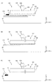
このとき、図5(A)に示されるように、ウエハ搬送アーム118により、C/D(不図示)により感応層(レジスト層)が設けられたウエハWがローディングポジションに向けて黒塗り矢印の方向(+Y方向)に搬送される。ウエハWがローディングディスク121の直下まで搬送されると、主制御装置20は、図5(B)に示されるように、ローディングディスク121を白抜き矢印の方向(−Z方向)に駆動し、ローディングディスク121の下面をウエハWの表面に近接する。なお、ローディングディスク121を駆動するのに代えて、又はこれとともに、ウエハ搬送アーム118を白抜き矢印と逆の方向(+Z方向)に駆動してもよい。
At this time, as shown in FIG. 5A, the
ローディングディスク121の下面がウエハWの表面まで100μmのオーダーまで近接すると、ローディングディスク121の吸着力がウエハWに及び、ウエハWがローディングディスク121に非接触で保持される。これにより、ウエハWは、Z軸方向、θx方向、及びθy方向への移動が制限される。主制御装置20は、図5(C)に示されるように、ウエハWを保持したローディングディスク121を白抜き矢印の方向(+Z方向)に微小駆動し、又はこれに代えて(或いはこれとともに)ウエハ搬送アーム118を白抜き矢印と逆の方向(−Z方向)に微小駆動し、ウエハWをリリースしたウエハ搬送アーム118を黒塗り矢印の方向(−Y方向)に待避する。
When the lower surface of the
次に、ローディングディスク121に保持されたウエハWをウエハステージWST上に載置する。
Next, wafer W held on
主制御装置20は、3つの撮像素子129を用いて、ローディングディスク121に保持されたウエハWの周縁(ノッチ等)を撮像する。主制御装置20は、これらの撮像結果から、ウエハWのX軸方向及びY軸方向の位置ずれと回転(θz回転)誤差とを求める。
The
図6(A)に示されるように、主制御装置20は、ウエハステージWSTをローディングポジションに移動する。ここで、主制御装置20は、上で求められた位置ずれ及び回転誤差を相殺する位置及び向きにウエハステージWSTを位置決めする。或いは、上で求められた位置ずれ及び回転誤差を記憶し、アライメント計測においてその結果を補正してもよい。
As shown in FIG. 6A,
ウエハステージWSTがローディングディスク121の直下に位置決めされると、図6(B)に示されるように、主制御装置20は、ウエハステージWST内からウエハホルダ(不図示)を介して3つのCTピン140を黒塗り矢印の方向(+Z方向)に出し、それらの先端をローディングディスク121に保持されたウエハWの裏面に当接してウエハWを(吸着)支持する。これにより、ウエハWは、さらに、X軸方向、Y軸方向、及びθz方向への動きが制限される。
When wafer stage WST is positioned immediately below
ウエハWが、ローディングディスク121に保持されることでそのZ軸方向、θx方向、及びθy方向への動きが制限され、3つのCTピン140により裏面が支持されることでそのX軸方向、Y軸方向、及びθz方向への動きが制限されると、図6(C)に示されるように、主制御装置20は、ローディングディスク121を白抜き矢印の方向(−Z方向)に駆動する。また、これに併せて3つのCTピン140を黒塗り矢印の方向(−Z方向)に動かしてウエハステージWST(ホルダWH)内に収納する。これにより、図7(A)に示されるように、ウエハWは、その6自由度方向の動きがほぼ制限された状態でウエハステージWST上に載置される。
The wafer W is held on the
ウエハWがウエハステージWST上にロードされると、図7(B)に示されるように、主制御装置20は、ローディングディスク121を白抜き矢印の方向(+Z方向)に待避し、その状態でローディングディスク121を停止させる。
When wafer W is loaded on wafer stage WST,
退避後(或いは退避と同時にでもよい)、図7(C)に示されるように、主制御装置20は、ローディングディスク121を構成する超音波スピーカ150を用いて、ウエハステージWST(ウエハホルダWH)上に載置されたウエハWに音圧(超音波)を放射して、ウエハWを音圧加振する。これにより、先述の通り、ウエハWの歪が解消される。
After evacuation (or at the same time as evacuation), as shown in FIG. 7C,
最後に、主制御装置20は、ウエハホルダWHを作動して、ウエハWをウエハホルダWH(すなわちウエハステージWST)上に吸着保持する。これにより、ウエハWがウエハステージWST上に保持される。そして、吸着保持の後(或いは吸着保持の前でもよい)、超音波スピーカ150からの音圧の放射を停止する。
Finally,
次に、本実施形態の露光装置100の露光動作を、簡単に説明する。
Next, the exposure operation of the
主制御装置20は、露光に先立って、先述の手順により、C/D(不図示)により感応層(レジスト層)が設けられたウエハWを、ローディングユニット120を用いてウエハステージWST(ウエハホルダ(不図示))上にロードする。
Prior to exposure,
主制御装置20は、アライメント検出系ASを用いて、ウエハWの表面に付与された(ウエハW上のサンプルショット領域に付設された)アライメントマークを検出し、アライメント計測(EGA)を実行する。それにより、XY平面内におけるウエハW上のショット領域の位置(さらに走査方向に関する倍率、光軸AX周りの回転、直交度)が定められる。なお、アライメント計測(EGA)の詳細は、例えば、特開平6−349705号公報に記載されている。
主制御装置20は、アライメント計測(EGA)の結果に従って、レチクルRのパターンの投影位置(投影光学系PLの投影中心)とウエハW上の各ショット領域の相対位置関係を算出する。その結果に従って、主制御装置20は、走査露光により、ウエハW上の全ショット領域内に、順次、レチクルRのパターンを露光する。
ウエハW上の各ショット領域に対する走査露光では、主制御装置20は、レチクル干渉計14と干渉計システム18の計測結果を監視して、レチクルステージRSTとウエハステージWSTをそれぞれの走査開始位置(加速開始位置)に移動させる。そして、主制御装置20は、両ステージRST,WSTをY軸方向に、ただし互いに逆向きに、相対駆動する。ここで、両ステージRST,WSTがそれぞれの目標速度に達すると、照明光ILによってレチクルRのパターン領域が照明され始め、走査露光が開始される。
In the scanning exposure for each shot area on wafer W,
主制御装置20は、走査露光中、Y軸方向についてのレチクルステージRSTの速度VrとウエハステージWSTの速度Vwとを投影光学系PLの投影倍率に対応する速度比に維持するように、レチクルステージRST及びウエハステージWSTを同期駆動する。
レチクルRがY軸方向に移動することにより、そのパターン領域の全域が照明光ILにより照明される。それと同時にウエハWがY軸方向に、ただしレチクルRと逆方向に、移動することにより、レチクルRのパターンがウエハW上に転写される。それにより、ウエハW上のショット領域の1つに対する走査露光が終了する。 As reticle R moves in the Y-axis direction, the entire pattern area is illuminated by illumination light IL. At the same time, the pattern of the reticle R is transferred onto the wafer W by moving the wafer W in the Y-axis direction, but in the opposite direction to the reticle R. Thereby, the scanning exposure for one of the shot areas on the wafer W is completed.
ショット領域の1つに対する走査露光が終了すると、主制御装置20は、ウエハステージWSTを、次のショット領域に対する走査開始位置(加速開始位置)へ移動(ステップ移動)させる。そして、主制御装置20は、先と同様に、次のショット領域に対する走査露光を行う。その他のショット領域に対する走査露光も、同様に行われる。このように、ショット領域間のステップ移動と各ショット領域に対する走査露光とを繰り返して、ウエハW上の全てのショット領域にレチクルRのパターンを転写する。
When the scanning exposure for one of the shot areas is completed,
露光が終了すると、主制御装置20は、ウエハステージWST(ウエハホルダ(不図示))から露光済みのウエハWをアンロードする。そして、先述の手順により、C/D(不図示)により感応層(レジスト層)が設けられた次のウエハWをウエハステージWST(ウエハホルダ(不図示))上にロードする。すなわち、ウエハステージWST上のウエハWを交換する。主制御装置20は、新しいウエハWに対して、同様に露光動作を繰り返す。
When the exposure is completed,
以上詳細に説明したように、本実施形態に係る露光装置100によると、音圧源(超音波スピーカ150)を用いてウエハステージWST(ウエハホルダWH)上に載置されたウエハWに向けて音圧(超音波)を放射することでウエハを音圧加振し、そして、ウエハホルダWHを用いてウエハを吸着保持する。これにより、歪みを生ずることなくウエハをウエハホルダ上に保持させることが可能となり、ひいては高いパターンの重ね精度を維持することが可能となる。
As described above in detail, according to the
なお、本実施形態の露光装置100では、音圧源(超音波スピーカ150)をローディングディスク121に設けたが、これに限らず、ローディングディスク121と独立に構成してもよい。例えば、投影光学系PL(投影ユニットPU)を支持するフレーム(不図示)に固定してもよい。また、ウエハステージWST(ウエハホルダWH)上に載置されたウエハWに音圧(超音波)を放射することができれば、露光装置100内のいずれの場所に設置してもよい。
In the
超音波スピーカからの発熱が周囲に影響を与えるおそれがある場合には、断熱あるいは温調装置等で周囲から超音波スピーカを隔離しておいてもよい。 If there is a possibility that the heat generated from the ultrasonic speaker may affect the surroundings, the ultrasonic speaker may be isolated from the surroundings by heat insulation or a temperature control device.
また、本実施形態の露光装置100では、音圧源(超音波スピーカ150)をローディングディスク121の底面の中央に設け、ウエハステージWST(ウエハホルダWH)上に載置されたウエハWの中央に音圧(超音波)を放射することとした。ここで、音圧(超音波)による振動がウエハ全体に伝わるのであれば、ウエハ上のより狭い範囲内に音圧(超音波)を放射してもよいし、ウエハの中央に限らず端部に放射してもよい。また、高周波帯域の音圧(超音波)は指向性が高いため、上方からの放射に限らず斜め上方からの放射としてもよいし、よりウエハから離れた位置から放射してもよい。
Further, in the
また、ウエハの微細な歪を解消するために、本実施形態では、ウエハ上で複数のノード(音圧の振幅がゼロまたは極小となる点、音圧の節)をもつ高次モードを有する音圧(超音波)を用いた。例えば、レチクルRのパターンが形成されるウエハW上のショット領域内のそれぞれに、少なくとも1つのノードを有する高次モードを採用することができる。 In this embodiment, in order to eliminate the fine distortion of the wafer, in this embodiment, a sound having a high-order mode having a plurality of nodes (a point where the amplitude of the sound pressure is zero or minimal, a node of the sound pressure) on the wafer. Pressure (ultrasound) was used. For example, a high-order mode having at least one node in each shot region on the wafer W where the pattern of the reticle R is formed can be adopted.
なお、本実施形態の露光装置100では、ウエハステージWST上にウエハWをロードするローディングポジションとウエハステージWST上からウエハWをアンロードするアンローディングポジションとを同じ位置に配置したが、これに限らず、異なる位置に配置し、それぞれにローディングユニット(アンローディングユニット)120を設けることとしてもよい。これにより、ウエハWの搬出入を他の動作と並行して行うことができること等により、スループットの向上が期待される。
In the
なお、上述の実施形態では、本発明が、液体(水)を介さずにウエハWの露光を行うドライタイプの露光装置に適用された場合について説明したが、これに限らず、例えば国際公開第99/49504号、欧州特許出願公開第1,420,298号明細書、国際公開第2004/055803号、米国特許第6,952,253号明細書などに開示されているように、投影光学系とウエハとの間に照明光の光路を含む液浸空間を形成し、投影光学系及び液浸空間の液体を介して照明光でウエハを露光する露光装置にも本発明を適用することができる。また、例えば米国特許出願公開第2008/0088843号明細書に開示される、液浸露光装置などにも、本発明を適用することができる。 In the above-described embodiment, the case where the present invention is applied to a dry type exposure apparatus that exposes the wafer W without using liquid (water) has been described. No. 99/49504, European Patent Application No. 1,420,298, International Publication No. 2004/055803, US Pat. No. 6,952,253, etc. The present invention can also be applied to an exposure apparatus that forms an immersion space including an optical path of illumination light between the wafer and the wafer, and exposes the wafer with illumination light through the projection optical system and the liquid in the immersion space. . The present invention can also be applied to an immersion exposure apparatus disclosed in, for example, US Patent Application Publication No. 2008/0088843.
また、上記実施形態では、ステップ・アンド・スキャン方式等の走査型露光装置に本発明が適用された場合について説明したが、これに限らず、ステッパなどの静止型露光装置に本発明を適用しても良い。また、ショット領域とショット領域とを合成するステップ・アンド・スティッチ方式の縮小投影露光装置、プロキシミティー方式の露光装置、又はミラープロジェクション・アライナーなどにも本発明は適用することができる。さらに、例えば米国特許第6,590,634号明細書、米国特許第5,969,441号明細書、米国特許第6,208,407号明細書などに開示されているように、複数のウエハステージを備えたマルチステージ型の露光装置にも本発明を適用できる。また、例えば米国特許第7,589,822号明細書などに開示されているように、ウエハステージとは別に、計測部材(例えば、基準マーク、及び/又はセンサなど)を含む計測ステージを備える露光装置にも本発明は適用が可能である。 In the above embodiment, the case where the present invention is applied to a scanning exposure apparatus such as a step-and-scan method has been described. However, the present invention is not limited to this, and the present invention is applied to a stationary exposure apparatus such as a stepper. May be. The present invention can also be applied to a step-and-stitch reduction projection exposure apparatus, a proximity exposure apparatus, or a mirror projection aligner that synthesizes a shot area and a shot area. Further, as disclosed in, for example, US Pat. No. 6,590,634, US Pat. No. 5,969,441, US Pat. No. 6,208,407, etc. The present invention can also be applied to a multi-stage type exposure apparatus provided with a stage. Further, as disclosed in, for example, US Pat. No. 7,589,822, an exposure including a measurement stage including a measurement member (for example, a reference mark and / or a sensor) separately from the wafer stage. The present invention can also be applied to an apparatus.
また、上記実施形態の露光装置における投影光学系は縮小系のみならず等倍及び拡大系のいずれでも良いし、投影光学系PLは屈折系のみならず、反射系及び反射屈折系のいずれでも良いし、その投影像は倒立像及び正立像のいずれでも良い。また、前述の照明領域及び露光領域はその形状が矩形であるものとしたが、これに限らず、例えば円弧、台形、あるいは平行四辺形などでも良い。 Further, the projection optical system in the exposure apparatus of the above embodiment may be not only a reduction system but also any of the same magnification and enlargement systems, and the projection optical system PL may be any of a reflection system and a catadioptric system as well as a refractive system. The projected image may be either an inverted image or an erect image. In addition, the illumination area and the exposure area described above are rectangular in shape, but the shape is not limited to this, and may be, for example, an arc, a trapezoid, or a parallelogram.
なお、上記実施形態の露光装置の光源は、ArFエキシマレーザに限らず、KrFエキシマレーザ(出力波長248nm)、F2レーザ(出力波長157nm)、Ar2レーザ(出力波長126nm)、Kr2レーザ(出力波長146nm)などのパルスレーザ光源、g線(波長436nm)、i線(波長365nm)などの輝線を発する超高圧水銀ランプなどを用いることも可能である。また、YAGレーザの高調波発生装置などを用いることもできる。この他、例えば米国特許第7,023,610号明細書に開示されているように、真空紫外光としてDFB半導体レーザ又はファイバーレーザから発振される赤外域、又は可視域の単一波長レーザ光を、例えばエルビウム(又はエルビウムとイッテルビウムの両方)がドープされたファイバーアンプで増幅し、非線形光学結晶を用いて紫外光に波長変換した高調波を用いても良い。 The light source of the exposure apparatus of the above embodiment is not limited to the ArF excimer laser, but is a KrF excimer laser (output wavelength 248 nm), F 2 laser (output wavelength 157 nm), Ar 2 laser (output wavelength 126 nm), Kr 2 laser ( It is also possible to use a pulse laser light source with an output wavelength of 146 nm, an ultrahigh pressure mercury lamp that emits a bright line such as g-line (wavelength 436 nm), i-line (wavelength 365 nm), and the like. A harmonic generator of a YAG laser or the like can also be used. In addition, as disclosed in, for example, U.S. Pat. No. 7,023,610, a single wavelength laser beam in the infrared region or visible region oscillated from a DFB semiconductor laser or fiber laser is used as vacuum ultraviolet light. For example, a harmonic that is amplified by a fiber amplifier doped with erbium (or both erbium and ytterbium) and wavelength-converted into ultraviolet light using a nonlinear optical crystal may be used.
また、上記実施形態では、露光装置の照明光ILとしては波長100nm以上の光に限らず、波長100nm未満の光を用いても良いことはいうまでもない。例えば、軟X線領域(例えば5〜15nmの波長域)のEUV(Extreme Ultraviolet)光を用いるEUV露光装置に本発明を適用することができる。その他、電子線又はイオンビームなどの荷電粒子線を用いる露光装置にも、本発明は適用できる。 In the above embodiment, it is needless to say that the illumination light IL of the exposure apparatus is not limited to light having a wavelength of 100 nm or more, and light having a wavelength of less than 100 nm may be used. For example, the present invention can be applied to an EUV exposure apparatus that uses EUV (Extreme Ultraviolet) light in a soft X-ray region (for example, a wavelength region of 5 to 15 nm). In addition, the present invention can be applied to an exposure apparatus using a charged particle beam such as an electron beam or an ion beam.
さらに、例えば米国特許第6,611,316号明細書に開示されているように、2つのレチクルパターンを、投影光学系を介してウエハ上で合成し、1回のスキャン露光によってウエハ上の1つのショット領域をほぼ同時に二重露光する露光装置にも本発明を適用することができる。 Further, as disclosed in, for example, US Pat. No. 6,611,316, two reticle patterns are synthesized on a wafer via a projection optical system, and 1 on the wafer by one scan exposure. The present invention can also be applied to an exposure apparatus that double exposes two shot areas almost simultaneously.
なお、上記実施形態でパターンを形成すべき物体(エネルギビームが照射される露光対象の物体)はウエハに限られるものでなく、ガラスプレート、セラミック基板、フィルム部材、あるいはマスクブランクスなど他の物体でも良い。 In the above embodiment, the object on which the pattern is to be formed (the object to be exposed to which the energy beam is irradiated) is not limited to the wafer, but may be another object such as a glass plate, a ceramic substrate, a film member, or a mask blank. good.
露光装置の用途としては半導体製造用の露光装置に限定されることなく、例えば、角型のガラスプレートに液晶表示素子パターンを転写する液晶用の露光装置や、有機EL、薄膜磁気ヘッド、撮像素子(CCD等)、マイクロマシン及びDNAチップなどを製造するための露光装置にも広く適用できる。また、半導体素子などのマイクロデバイスだけでなく、光露光装置、EUV露光装置、X線露光装置、及び電子線露光装置などで使用されるレチクル又はマスクを製造するために、ガラス基板又はシリコンウエハなどに回路パターンを転写する露光装置にも本発明を適用できる。 The use of the exposure apparatus is not limited to the exposure apparatus for semiconductor manufacturing, but for example, an exposure apparatus for liquid crystal that transfers a liquid crystal display element pattern to a square glass plate, an organic EL, a thin film magnetic head, an image sensor (CCD, etc.), micromachines, DNA chips and the like can also be widely applied to exposure apparatuses. Further, in order to manufacture reticles or masks used in not only microdevices such as semiconductor elements but also light exposure apparatuses, EUV exposure apparatuses, X-ray exposure apparatuses, electron beam exposure apparatuses, etc., glass substrates or silicon wafers, etc. The present invention can also be applied to an exposure apparatus that transfers a circuit pattern.
半導体素子などの電子デバイスは、デバイスの機能・性能設計を行うステップ、この設計ステップに基づいたレチクルを製作するステップ、シリコン材料からウエハを製作するステップ、前述した実施形態の露光装置(パターン形成装置)及びその露光方法によりマスク(レチクル)のパターンをウエハに転写するリソグラフィステップ、露光されたウエハを現像する現像ステップ、レジストが残存している部分以外の部分の露出部材をエッチングにより取り去るエッチングステップ、エッチングが済んで不要となったレジストを取り除くレジスト除去ステップ、デバイス組み立てステップ(ダイシング工程、ボンディング工程、パッケージ工程を含む)、検査ステップ等を経て製造される。この場合、リソグラフィステップで、上記実施形態の露光装置を用いて前述の露光方法が実行され、ウエハ上にデバイスパターンが形成されるので、高集積度のデバイスを生産性良く製造することができる。 An electronic device such as a semiconductor element includes a step of designing a function / performance of the device, a step of manufacturing a reticle based on the design step, a step of manufacturing a wafer from a silicon material, and the exposure apparatus (pattern forming apparatus) of the above-described embodiment. And a lithography step for transferring the mask (reticle) pattern to the wafer by the exposure method, a development step for developing the exposed wafer, and an etching step for removing the exposed member other than the portion where the resist remains by etching, It is manufactured through a resist removal step for removing a resist that has become unnecessary after etching, a device assembly step (including a dicing process, a bonding process, and a packaging process), an inspection step, and the like. In this case, in the lithography step, the exposure method described above is executed using the exposure apparatus of the above embodiment, and a device pattern is formed on the wafer. Therefore, a highly integrated device can be manufactured with high productivity.
20…主制御装置、100…露光装置、118…ウエハ搬送アーム、120…ローディングユニット、121…ローディングディスク、124…ベルヌーイカップ、125…配管、128…温度センサ、129…撮像素子、140…CTピン、150…超音波スピーカ、PL…投影光学系、PU…投影ユニット、W…ウエハ、WH…ウエハホルダ、WST…ウエハステージ。
DESCRIPTION OF
Claims (21)
前記物体を載置し吸着して保持可能な保持部材と、 A holding member on which the object can be placed, adsorbed and held;
前記保持部材に載置された前記物体に音圧を放射する音圧源と、 A sound pressure source that radiates sound pressure to the object placed on the holding member;
前記保持部材と前記音圧源とを制御する制御装置と、 A control device for controlling the holding member and the sound pressure source;
を備え、With
前記制御装置は、前記保持部材に載置された前記物体への前記音圧の放射が終了してから、前記吸着の動作を開始する保持装置。 The control device is a holding device that starts the suction operation after the emission of the sound pressure to the object placed on the holding member ends.
前記物体を載置して保持可能な保持部材と、
前記保持部材に載置された前記物体に斜め上方から音圧を放射する音圧源と、
を備える保持装置。 A holding device for holding an object,
A holding member capable of placing and holding the object;
A sound pressure source that radiates sound pressure obliquely from above to the object placed on the holding member ;
A holding device.
請求項1〜8のいずれか一項に記載の保持装置を備え、
前記保持部材で保持されている物体に対して前記エネルギビームを照射する露光装置。 An exposure apparatus that irradiates an energy beam to form a pattern on an object,
A holding device according to any one of claims 1 to 8 ,
An exposure apparatus that irradiates the energy beam onto an object held by the holding member.
前記音圧源は前記フレームに設けられる請求項9に記載の露光装置。The exposure apparatus according to claim 9, wherein the sound pressure source is provided in the frame.
前記物体を吸着して保持可能な保持部材に前記物体を載置することと、 Placing the object on a holding member capable of adsorbing and holding the object;
前記保持部材に載置された前記物体に音圧源の発生した音圧を放射することと、を含み、 Radiating sound pressure generated by a sound pressure source to the object placed on the holding member,
前記保持部材に載置された前記物体への前記音圧の放射が終了してから、前記吸着の動作を開始する保持方法。 A holding method of starting the suction operation after the radiation of the sound pressure to the object placed on the holding member is completed.
前記物体を保持可能な保持部材に前記物体を載置することと、
前記保持部材に載置された前記物体に斜め上方から音圧源の発生する音圧を放射することと、
前記物体に前記音圧を放射している状態で、前記保持部材で前記物体に対する前記吸着の動作を行なうことと、
を含む保持方法。 A holding method for holding an object,
And placing the object to the holding member capable of holding the object,
And to radiate the sound pressure occurring in the sound pressure source from obliquely above in the placed the object on the holding member,
Performing the adsorption operation on the object with the holding member in a state where the sound pressure is radiated to the object;
Holding method.
前記保持部材に載置された前記物体への前記音圧の放射が終了してから、前記吸着の動作を開始する請求項11〜16のいずれか一項に記載の保持方法。The holding method according to any one of claims 11 to 16, wherein the suction operation is started after the emission of the sound pressure to the object placed on the holding member is completed.
請求項11〜19のいずれか一項に記載の保持方法を利用して前記保持部材に保持された前記物体に対して前記エネルギビームを照射する露光方法。 An exposure method for irradiating an energy beam to form a pattern on an object,
EXPOSURE how to irradiates the energy beam method with respect to the object held by the holding member by using the holding according to any one of claims 11-19.
前記パターンが形成された前記物体を現像することと、
を含むデバイス製造方法。
Using the exposure method of claim 20 to form a pattern on the object;
Developing the object on which the pattern is formed;
A device manufacturing method including:
Priority Applications (1)
| Application Number | Priority Date | Filing Date | Title |
|---|---|---|---|
| JP2016213437A JP6380506B2 (en) | 2016-10-31 | 2016-10-31 | Holding apparatus and holding method, exposure apparatus and exposure method, and device manufacturing method |
Applications Claiming Priority (1)
| Application Number | Priority Date | Filing Date | Title |
|---|---|---|---|
| JP2016213437A JP6380506B2 (en) | 2016-10-31 | 2016-10-31 | Holding apparatus and holding method, exposure apparatus and exposure method, and device manufacturing method |
Related Parent Applications (1)
| Application Number | Title | Priority Date | Filing Date |
|---|---|---|---|
| JP2013004300A Division JP2014138004A (en) | 2013-01-15 | 2013-01-15 | Holding device and holding method, exposure device and exposure method, and method of manufacturing device |
Related Child Applications (1)
| Application Number | Title | Priority Date | Filing Date |
|---|---|---|---|
| JP2018141982A Division JP6653068B2 (en) | 2018-07-30 | 2018-07-30 | Holding apparatus and holding method, exposure apparatus and exposure method, and device manufacturing method |
Publications (3)
| Publication Number | Publication Date |
|---|---|
| JP2017033021A JP2017033021A (en) | 2017-02-09 |
| JP2017033021A5 JP2017033021A5 (en) | 2017-06-08 |
| JP6380506B2 true JP6380506B2 (en) | 2018-08-29 |
Family
ID=57989444
Family Applications (1)
| Application Number | Title | Priority Date | Filing Date |
|---|---|---|---|
| JP2016213437A Active JP6380506B2 (en) | 2016-10-31 | 2016-10-31 | Holding apparatus and holding method, exposure apparatus and exposure method, and device manufacturing method |
Country Status (1)
| Country | Link |
|---|---|
| JP (1) | JP6380506B2 (en) |
Cited By (1)
| Publication number | Priority date | Publication date | Assignee | Title |
|---|---|---|---|---|
| JP2018194853A (en) * | 2018-07-30 | 2018-12-06 | 株式会社ニコン | Holding device, holding method, exposure device and exposure method and device production method |
Family Cites Families (5)
| Publication number | Priority date | Publication date | Assignee | Title |
|---|---|---|---|---|
| JPH05226221A (en) * | 1992-02-18 | 1993-09-03 | Mitsubishi Electric Corp | Apparatus and method for positioning of wafer |
| JPH07273004A (en) * | 1994-03-29 | 1995-10-20 | Hitachi Ltd | Sample holding device |
| JP2005093968A (en) * | 2003-09-19 | 2005-04-07 | Kazumasa Onishi | Vacuum chuck |
| JP2010245332A (en) * | 2009-04-07 | 2010-10-28 | Canon Inc | Semiconductor aligner |
| JP5682106B2 (en) * | 2009-09-11 | 2015-03-11 | 株式会社ニコン | Substrate processing method and substrate processing apparatus |
-
2016
- 2016-10-31 JP JP2016213437A patent/JP6380506B2/en active Active
Cited By (1)
| Publication number | Priority date | Publication date | Assignee | Title |
|---|---|---|---|---|
| JP2018194853A (en) * | 2018-07-30 | 2018-12-06 | 株式会社ニコン | Holding device, holding method, exposure device and exposure method and device production method |
Also Published As
| Publication number | Publication date |
|---|---|
| JP2017033021A (en) | 2017-02-09 |
Similar Documents
| Publication | Publication Date | Title |
|---|---|---|
| JP7243797B2 (en) | Transport system, exposure apparatus, and transport method | |
| CN108336011B (en) | Carrying-in method, carrying system, exposure apparatus, and device manufacturing method | |
| TWI770500B (en) | Substrate holding device, exposure apparatus and device manufacturing method | |
| JP5273522B2 (en) | Exposure apparatus and device manufacturing method | |
| US9575417B2 (en) | Exposure apparatus including a mask holding device which holds a periphery area of a pattern area of the mask from above | |
| JP2007273693A (en) | Member, method, and device for holding substrate, and device and method for exposure | |
| JP2014003259A (en) | Load method, substrate holding apparatus, and exposure apparatus | |
| JP2005093654A (en) | Stage device, aligner using the same, and device manufacturing method using aligner | |
| JP2014165470A (en) | Conveyance system and method, exposure apparatus and method, and device manufacturing method | |
| JP2014204079A (en) | Exposure device and exposure method, and device manufacturing method | |
| JP4348734B2 (en) | Substrate holding apparatus, exposure apparatus, and device manufacturing method | |
| JP6380506B2 (en) | Holding apparatus and holding method, exposure apparatus and exposure method, and device manufacturing method | |
| JP2005044882A (en) | Transporting device and aligner | |
| JP6653068B2 (en) | Holding apparatus and holding method, exposure apparatus and exposure method, and device manufacturing method | |
| JP6485687B2 (en) | Holding apparatus, object support apparatus, exposure apparatus, and device manufacturing method | |
| JP2014138004A (en) | Holding device and holding method, exposure device and exposure method, and method of manufacturing device | |
| JP2014127655A (en) | Suction device, method, exposure device, and device manufacturing method | |
| JP6086292B2 (en) | Substrate holding apparatus and exposure apparatus | |
| JP2014138078A (en) | Conveyance system and conveyance method, exposure device and exposure method, and method of manufacturing device | |
| JP2014127654A (en) | Suction apparatus, method, and exposure device | |
| JP6015983B2 (en) | Object exchange system, exposure apparatus, flat panel display manufacturing method, and device manufacturing method | |
| JP2014154647A (en) | Measuring apparatus and exposure device |
Legal Events
| Date | Code | Title | Description |
|---|---|---|---|
| A621 | Written request for application examination |
Free format text: JAPANESE INTERMEDIATE CODE: A621 Effective date: 20161130 |
|
| A521 | Request for written amendment filed |
Free format text: JAPANESE INTERMEDIATE CODE: A523 Effective date: 20170419 |
|
| A977 | Report on retrieval |
Free format text: JAPANESE INTERMEDIATE CODE: A971007 Effective date: 20170816 |
|
| A131 | Notification of reasons for refusal |
Free format text: JAPANESE INTERMEDIATE CODE: A131 Effective date: 20170908 |
|
| A601 | Written request for extension of time |
Free format text: JAPANESE INTERMEDIATE CODE: A601 Effective date: 20171106 |
|
| A521 | Request for written amendment filed |
Free format text: JAPANESE INTERMEDIATE CODE: A523 Effective date: 20180105 |
|
| TRDD | Decision of grant or rejection written | ||
| A01 | Written decision to grant a patent or to grant a registration (utility model) |
Free format text: JAPANESE INTERMEDIATE CODE: A01 Effective date: 20180703 |
|
| A61 | First payment of annual fees (during grant procedure) |
Free format text: JAPANESE INTERMEDIATE CODE: A61 Effective date: 20180716 |
|
| R150 | Certificate of patent or registration of utility model |
Ref document number: 6380506 Country of ref document: JP Free format text: JAPANESE INTERMEDIATE CODE: R150 |
|
| R250 | Receipt of annual fees |
Free format text: JAPANESE INTERMEDIATE CODE: R250 |
|
| R250 | Receipt of annual fees |
Free format text: JAPANESE INTERMEDIATE CODE: R250 |
|
| R250 | Receipt of annual fees |
Free format text: JAPANESE INTERMEDIATE CODE: R250 |