JP6376743B2 - IMAGING DEVICE, IMAGING SYSTEM, IMAGING DEVICE CONTROL METHOD, IMAGING SYSTEM CONTROL METHOD, AND PROGRAM - Google Patents
IMAGING DEVICE, IMAGING SYSTEM, IMAGING DEVICE CONTROL METHOD, IMAGING SYSTEM CONTROL METHOD, AND PROGRAM Download PDFInfo
- Publication number
- JP6376743B2 JP6376743B2 JP2013217291A JP2013217291A JP6376743B2 JP 6376743 B2 JP6376743 B2 JP 6376743B2 JP 2013217291 A JP2013217291 A JP 2013217291A JP 2013217291 A JP2013217291 A JP 2013217291A JP 6376743 B2 JP6376743 B2 JP 6376743B2
- Authority
- JP
- Japan
- Prior art keywords
- image
- imaging
- unit
- command
- type
- Prior art date
- Legal status (The legal status is an assumption and is not a legal conclusion. Google has not performed a legal analysis and makes no representation as to the accuracy of the status listed.)
- Active
Links
Images


Classifications
-
- H—ELECTRICITY
- H04—ELECTRIC COMMUNICATION TECHNIQUE
- H04N—PICTORIAL COMMUNICATION, e.g. TELEVISION
- H04N23/00—Cameras or camera modules comprising electronic image sensors; Control thereof
- H04N23/60—Control of cameras or camera modules
- H04N23/66—Remote control of cameras or camera parts, e.g. by remote control devices
- H04N23/661—Transmitting camera control signals through networks, e.g. control via the Internet
-
- G—PHYSICS
- G06—COMPUTING; CALCULATING OR COUNTING
- G06T—IMAGE DATA PROCESSING OR GENERATION, IN GENERAL
- G06T7/00—Image analysis
- G06T7/70—Determining position or orientation of objects or cameras
-
- H—ELECTRICITY
- H04—ELECTRIC COMMUNICATION TECHNIQUE
- H04L—TRANSMISSION OF DIGITAL INFORMATION, e.g. TELEGRAPHIC COMMUNICATION
- H04L12/00—Data switching networks
- H04L12/02—Details
- H04L12/10—Current supply arrangements
-
- H—ELECTRICITY
- H04—ELECTRIC COMMUNICATION TECHNIQUE
- H04L—TRANSMISSION OF DIGITAL INFORMATION, e.g. TELEGRAPHIC COMMUNICATION
- H04L12/00—Data switching networks
- H04L12/28—Data switching networks characterised by path configuration, e.g. LAN [Local Area Networks] or WAN [Wide Area Networks]
-
- H—ELECTRICITY
- H04—ELECTRIC COMMUNICATION TECHNIQUE
- H04N—PICTORIAL COMMUNICATION, e.g. TELEVISION
- H04N7/00—Television systems
- H04N7/18—Closed-circuit television [CCTV] systems, i.e. systems in which the video signal is not broadcast
-
- H—ELECTRICITY
- H04—ELECTRIC COMMUNICATION TECHNIQUE
- H04N—PICTORIAL COMMUNICATION, e.g. TELEVISION
- H04N23/00—Cameras or camera modules comprising electronic image sensors; Control thereof
- H04N23/60—Control of cameras or camera modules
- H04N23/63—Control of cameras or camera modules by using electronic viewfinders
- H04N23/633—Control of cameras or camera modules by using electronic viewfinders for displaying additional information relating to control or operation of the camera
Landscapes
- Engineering & Computer Science (AREA)
- Signal Processing (AREA)
- Multimedia (AREA)
- Computer Networks & Wireless Communication (AREA)
- Computer Vision & Pattern Recognition (AREA)
- Physics & Mathematics (AREA)
- General Physics & Mathematics (AREA)
- Theoretical Computer Science (AREA)
- Studio Devices (AREA)
- Closed-Circuit Television Systems (AREA)
Description
本発明は、撮像装置、撮像システム、撮像装置の制御方法、撮像システムの制御方法、及びプログラムに関するものである、特に、撮像画像を回転させる技術に関する。 The present invention relates to an imaging apparatus, an imaging system, an imaging apparatus control method, an imaging system control method, and a program, and more particularly to a technique for rotating a captured image.
従来、撮像部により撮像された撮像画像を回転させることができる撮像装置が知られている。 2. Description of the Related Art Conventionally, an imaging apparatus that can rotate a captured image captured by an imaging unit is known.
特許文献1には、撮像部により撮像された撮像画像を回転させ、回転させた画像をネットワーク経由でクライアント装置に配信する撮像装置が開示されている。 Patent Document 1 discloses an imaging apparatus that rotates a captured image captured by an imaging unit and distributes the rotated image to a client apparatus via a network.
また、撮像部により撮像された撮像画像に関する情報として、撮像画像の所定の位置に重畳される重畳画像やマスク画像等が知られている。ここで、重畳画像は、所定の文字や図形などから成る画像である。 Further, as information related to the captured image captured by the imaging unit, a superimposed image, a mask image, and the like that are superimposed at a predetermined position of the captured image are known. Here, the superimposed image is an image made up of predetermined characters, figures and the like.
特許文献2には、カメラの筐体をパン又はチルト方向に移動させると、筐体を移動させた方向に対応して表示画面上のカーソルの位置を移動させる撮像装置が開示されている。 Patent Document 2 discloses an imaging apparatus that moves the position of the cursor on the display screen in accordance with the direction in which the housing is moved when the housing of the camera is moved in the pan or tilt direction.
特許文献3には、カメラがパン、チルトにより撮像方向を変えた場合でも、所定の被写体をマスクし続けるようにして、マスク画像を重畳する撮像装置が開示されている。 Patent Document 3 discloses an imaging apparatus that superimposes a mask image so as to continue masking a predetermined subject even when the camera changes the imaging direction by panning and tilting.
しかしながら、上述の特許文献1に開示の技術では、撮像部により撮像された撮像画像を回転させることにより、この撮像画像と重畳画像やマスク画像等のこの撮像画像に関する情報との間に不整合が発生してしまうことがあった。 However, in the technique disclosed in Patent Document 1 described above, by rotating the captured image captured by the imaging unit, there is a mismatch between the captured image and information related to the captured image such as a superimposed image and a mask image. It sometimes occurred.
本発明は、上記のような点に鑑みてなされたものであり、撮像画像の回転に応じ、この撮像画像に関する情報のうち適切な情報を回転させることができるようになるものである。 The present invention has been made in view of the above points, and according to the rotation of the captured image, appropriate information can be rotated among the information regarding the captured image.
上記目的を達成するために、本発明の撮像装置は、外部装置とネットワークを介して通信可能な撮像装置であって、被写体を撮像するための撮像手段と、前記撮像手段から出力された撮像画像を回転処理して得られる画像を配信画像として出力させるための命令を、前記外部装置からネットワークを介して受信する受信手段と、前記受信手段によって前記命令が受信された場合に、重畳情報に対して設定されたフラグに従って、前記撮像手段から出力された撮像画像を回転処理して得られる配信画像に前記重畳情報を重畳させるように重畳手段を制御する制御手段とを有し、前記制御手段は、前記重畳情報に対して設定されたフラグに従って、前記配信画像が表示画面上に表示されたときの所定の位置に重畳される第1の重畳情報として前記重畳情報を前記配信画像に重畳させるか、あるいは、前記回転処理に追従して重畳される第2の重畳情報として前記重畳情報を前記配信画像に重畳させるかを判定することを特徴とする。 To achieve the above object, an imaging apparatus of the present invention is a communication imaging device capable of an external apparatus via a network, and an imaging means order to image a subject, output from the previous SL imaging means the instruction for outputting a captured image an image obtained by the rotation processing as a distribution image, a receiving means for receiving via a network from the external apparatus, when the instruction is received by the receiving unit, according to the set flag for superimposing information, and a control means for controlling the superimposing means so as to superimpose the superimposed information to the distribution image is obtained by rotation processing a captured image output from said image pickup means, The control means includes the superimposing information as first superimposing information superimposed on a predetermined position when the distribution image is displayed on a display screen according to a flag set for the superimposing information. Or to superimpose tatami information on the distribution image, or, wherein the determining whether to superimpose the superimposed information to the distribution image as a second superimposition information to be superimposed to follow the rotation processing.
本発明によれば、撮像画像の回転に応じ、この撮像画像に関する情報のうち適切な情報を回転させることができるようになる。 According to the present invention, according to the rotation of the captured image, appropriate information can be rotated among the information regarding the captured image.
以下に、本発明の好ましい実施の形態を、添付の図面に基づいて詳細に説明する。なお、以下の実施例において示す構成は一例に過ぎず、本発明は、図示された構成に限定されるものではない。また、以下の実施例におけるコマンド及び座標系は、例えばOpen Network Video Interface Forum(以下ONVIFと称する場合がある)規格に基づいて定められているものとする。 Hereinafter, preferred embodiments of the present invention will be described in detail with reference to the accompanying drawings. The configurations shown in the following embodiments are merely examples, and the present invention is not limited to the illustrated configurations. In addition, commands and coordinate systems in the following embodiments are determined based on, for example, the Open Network Video Interface Forum (hereinafter sometimes referred to as ONVIF) standard.
(実施例1)
以下に、図1を参照して本実施例に係るネットワーク構成について説明する。
Example 1
The network configuration according to this embodiment will be described below with reference to FIG.
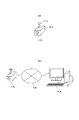
図1(a)は、本実施例に係る監視カメラの一例を示す図である。図1における監視カメラ1000は、レンズを含む筐体1101、及びアーム機構1102を備える。アーム機構1102は、監視カメラ1000を天井等の設置場所から吊り下げる。又、アーム機構1102は、筐体1101をパン方向及びチルト方向に回転させることにより監視カメラ1000の撮像方向を変更可能であり、且つこの撮像方向を固定することができる。
FIG. 1A is a diagram illustrating an example of a monitoring camera according to the present embodiment. A
なお、本実施例における監視カメラ1000は、動画像を撮像する撮像装置であり、より詳細には、監視に用いられるネットワークカメラであるものとする。又、アーム機構1102には、筐体1101をパン方向に回転させるためのステッピングモータと、筐体1101をチルト方向に回転させるためのステッピングモータと、が設けられているものとする。
Note that the
続いて、図1(b)は、本実施例に係る監視システムのシステム構成の一例を示す図である。 FIG. 1B is a diagram illustrating an example of a system configuration of the monitoring system according to the present embodiment.
本実施例における監視システムにおいて、監視カメラ1000とクライアント装置2000とは、IPネットワーク網1500を介して(ネットワーク経由で)相互に通信可能な状態で接続される。なお、本実施例におけるクライアント装置2000は、PC等の外部装置の一例である。又、本実施例における監視システムは、撮像システムに相当する。
In the monitoring system according to the present embodiment, the
なお、IPネットワーク網1500は、例えばEthernet(登録商標)等の通信規格を満足する複数のルータ、スイッチ、ケーブル等から構成されるものとする。しかしながら、本実施例においては、監視カメラ1000とクライアント装置2000との間の通信を行うことができるものであれば、その通信規格、規模、構成を問わない。
Note that the
例えば、IPネットワーク網1500は、インターネットや有線LAN(Local Area Network)、無線LAN(Wireless LAN)、WAN(Wide Area Network)等により構成されていても良い。なお、本実施例における監視カメラ1000は、例えば、PoE(Power Over Ethernet(登録商標))に対応していても良く、LANケーブルを介して電力を供給されても良い。
For example, the
クライアント装置2000は、監視カメラ1000に対し、各種コマンドを送信する。これらのコマンドは、例えば、後述の撮像パラメータを変更するためのコマンドや、画像ストリーミングを開始させるためのコマンド等である。なお、これらのコマンドの詳細は、後述する。また、監視カメラ1000は、これらのコマンドに対するレスポンスや画像ストリーミングをクライアント装置2000に送信する。
The
続いて、図2は、本実施例に係る監視カメラ1000のハードウェア構成の一例を示す図である。図2において、レンズ1001は、被写体の像を撮像部1002に結像する。撮像部1002は、レンズ1001により結像された被写体の像を撮像することにより、撮像画像を生成する。そして、撮像部1002は、生成した撮像画像を画像処理部1003に出力する。
Next, FIG. 2 is a diagram illustrating an example of a hardware configuration of the
画像処理部1003は、後述の制御部1008の指示に従い、撮像部1002から出力された撮像画像に画像処理を施す。そして、画像処理部1003は、画像処理を施した撮像画像を、配信画像として圧縮符号化部1004に出力する。圧縮符号化部1004は、制御部1008の指示に従い、画像処理部1003から出力された撮像画像を圧縮符号化する。
The
なお、画像処理部1003は、撮像部1002から出力された撮像画像に含まれる物体を検知することもできる。例えば、画像処理部1003は、撮像部1002から出力された撮像画像に含まれる移動物体を検知することができる。
Note that the
通信部1005は、圧縮符号化部1004で圧縮符号化された配信画像を、IPネットワーク網1500経由でクライアント装置2000に配信する。そして、通信部1005は、クライアント装置2000から送信されたOSD設定コマンドを、IPネットワーク網1500を介して受信する。更に、通信部1005は、クライアント装置2000から送信された符号化設定コマンドを、IPネットワーク網1500を介して受信する。
The
又、通信部1005は、撮像画像に対する設定コマンド(以下、画像設定コマンドと称することがある)を受信する。この画像設定コマンドは、例えば、画像サイズの設定コマンド、被写体像に対するホワイトバランス及びゲイン等の露出制御に関する設定コマンド等を含む。
In addition, the
レンズ制御部1006は、被写体の像に応じて絞りを変化させ、フォーカス位置を調整させることでピント合わせを実行させ、赤外線遮断フィルターの挿脱等を行わせるように、レンズ1001を制御する。又、OSD生成部1007は、制御部1008の指示に従い、OSD画像を生成する。そして、OSD生成部1007は、生成したOSD画像を圧縮符号化部1004に出力する。
The
なお、本実施例では、文字情報に対応するOSD画像は、英数字及び記号といった文字と、この文字の背景と、で構成されるものとする。また、本実施例では、図形情報に対応するOSD画像は、図形と、この図形の背景と、で構成されるものとする。更に、この文字の背景及びこの図形の背景には、色(背景色)を設定することができるものとする。 In this embodiment, the OSD image corresponding to the character information is composed of characters such as alphanumeric characters and symbols and the background of the characters. In this embodiment, it is assumed that the OSD image corresponding to the graphic information includes a graphic and a background of the graphic. Furthermore, a color (background color) can be set for the background of this character and the background of this figure.
ここで、圧縮符号化部1004は、画像処理部1003が出力した配信画像に、OSD生成部1007が出力したOSD画像を合成する。例えば、圧縮符号化部1004は、画像処理部1003が出力した配信画像に対し、OSD生成部1007が出力したOSD画像を重畳する。次に、圧縮符号化部1004は、合成した配信画像を圧縮符号化する。そして、圧縮符号化部1004は、圧縮符号化した配信画像を通信部1005に出力する。
Here, the
なお、本実施例における圧縮符号化部1004は、撮像部1002から出力された撮像画像にOSD画像を重畳する重畳部に相当する。又、本実施例におけるOSD画像は、重畳情報に相当する。
Note that the
制御部1008は、監視カメラ1000の全体の制御を行う。制御部1008は、例えばCPU(Central Processing Unit)により構成され、後述の記憶部1009に記憶されたプログラムを実行する。又は、制御部1008は、ハードウェアを用いて制御を行うこととしても良い。
The
制御部1008は、通信部1005により受信された画像設定コマンドを解析する。次に、制御部1008は、解析した画像設定コマンドに基づき、画像設定情報を生成する。そして、制御部1008は、生成した画像設定情報を画像処理部1003に出力し、この出力と同時に、生成した画像設定情報を記憶部1009に記憶させる。この画像設定情報は、撮像画像の回転に関する回転情報を含む。
The
なお、制御部1008は、監視カメラ1000の起動時に、記憶部1009に記憶された画像設定情報を読み出し、読み出した画像設定情報を画像処理部1003に出力する。画像処理部1003は、制御部1008から出力された画像設定情報に従い、撮像部1002から出力された撮像画像に画像処理を施し、画像処理を施した配信画像を圧縮符号化部1004に出力する。
Note that the
制御部1008は、通信部1005により受信されたOSD設定コマンドを解析する。次に、制御部1008は、解析したOSD設定コマンドに基づき、OSD設定情報を生成する。そして、制御部1008は、生成したOSD設定情報をOSD生成部1007に出力し、この出力と同時に、生成したOSD設定情報を記憶部1009に記憶させる。
The
なお、OSD生成部1007は、制御部1008が出力したOSD設定情報に従い、OSD画像を生成する。ここで、1つのOSD設定情報から1つのOSD画像が生成されるものとする。又、このOSD設定情報は、このOSD画像の色、及び重畳位置情報等を含む。ここで、重畳位置情報は、画像処理部1003から出力された配信画像にOSD画像を重畳する位置を示す情報である。
Note that the
制御部1008は、通信部1005により受信された符号化設定コマンドを解析する。次に、制御部1008は、解析した符号化設定コマンドに基づき、符号化設定情報を生成する。そして、制御部1008は、生成した符号化設定情報を記憶部1009に記憶させた後、生成した符号化設定情報を圧縮符号化部1004に出力する。
The
なお、制御部1008から出力された符号化設定情報は、例えば、データの符号化方式、画像サイズ(或いは画像の解像度)等に関する指定情報を含む。
Note that the encoding setting information output from the
圧縮符号化部1004は、画像処理部1003から出力された配信画像を、制御部1008が出力した符号化設定情報で指定された画像サイズ若しくは画像の解像度に変換する。又は、圧縮符号化部1004は、画像処理部1003から出力された撮像画像とOSD生成部1007から出力されたOSD画像とが合成された画像を、制御部1008が出力した符号化設定情報で指定された画像サイズ若しくは画像の解像度に変換する。
The
そして、圧縮符号化部1004は、変換した配信画像を、制御部1008が出力した符号化設定情報で指定された符号化方式で圧縮符号化する。なお、本実施例では、この指定された符号化形式には、例えば、JPEG、MPEG、H.264、及びH.265等が含まれるものとする。
Then, the
上記のごとく動作することにより、本実施例における監視カメラ1000は、同一被写体の画像を、画像サイズがそれぞれ異なる複数の画像に変換することができる。次に、監視カメラ1000は、変換した複数の画像を、符号化方式がそれぞれ異なる複数の画像に圧縮符号化することができる。そして、監視カメラ1000は、圧縮符号化された画像のそれぞれを、ほぼ同時に、ストリーミング配信することができる。
By operating as described above, the
なお、ストリーミング配信される画像は、通信部1005を介して外部に出力される。
Note that the image that is streamed is output to the outside via the
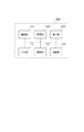
続いて、図3は、本実施例に係るクライアント装置2000のハードウェア構成の一例を示す図である。本実施例におけるクライアント装置2000は、IPネットワーク網1500に接続されるコンピュータ装置として構成される。
Next, FIG. 3 is a diagram illustrating an example of a hardware configuration of the
制御部2001は、クライアント装置2000の全体の制御を行う。制御部2001は、例えば、CPUにより構成され、後述の記憶部2002に記憶されたプログラムを実行する。又、制御部2001は、ハードウェアを用いて制御を行うこととしてもよい。そして、記憶部2002は、制御部2001が実行するプログラム格納領域、プログラム実行中のワーク領域、データの格納領域として使用される。
The
通信部2006は、制御部2001の指示を受け、監視カメラ1000にコマンド等を送信する。又、通信部2006は、制御部2001の指示を受け、監視カメラ1000から、コマンドのレスポンスやストリーミング配信された画像等を受信する。
A
入力部2004は、例えば、ボタン、十字キ―、タッチパネル、マウスなどで構成される。この入力部2004は、ユーザからの指示の入力を受け付ける。例えば、入力部2004は、ユーザからの指示として、監視カメラ1000に対する各種のコマンドの送信指示の入力を受け付けることができる。
The
又、入力部2004は、制御部2001が記憶部2002に記憶されたプログラムを実行することにより生成されるユーザへの問い合わせメッセージ等に対するユーザの応答の入力を受け付けることができる。
The
復号部2005は、通信部2006から出力された画像を復号し且つ伸長する。そして、復号部2005は、この復号し且つ伸長された画像を表示部2003に出力する。表示部2003は、復号部2005から出力された画像を表示する。又、表示部2003は、制御部2001が記憶部2002に記憶されたプログラムを実行することにより生成されるユーザへの問い合わせメッセージ等を表示させることができる。
The
なお、本実施例における表示部2003は、例えば、LCD、有機ELディスプレイ等で構成されるものとする。
In addition, the
以上、監視カメラ1000及びクライアント装置2000のそれぞれの内部構成について説明したが、図2及び図3に示す処理ブロックは、本発明における撮像装置の好適な実施例を説明したものであり、この限りではない。音声入力部や音声出力部を備えるなど、本発明の要旨の範囲内で、種々の変形及び変更が可能である。
The internal configuration of each of the
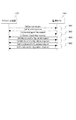
続いて、図4は、監視カメラ1000とクライアント装置2000との間における、ストリーミング配信される画像のパラメータの設定開始から画像がストリーミング配信されるまでの、典型的なコマンドシーケンスを説明するためのシーケンス図である。
Next, FIG. 4 is a sequence for explaining a typical command sequence between the
なお、本実施例におけるトランザクションとは、クライアント装置2000から監視カメラ1000へ送信されるコマンドと、それに対して監視カメラ1000がクライアント装置2000へ返送するレスポンスのペアのことを指している。
Note that the transaction in this embodiment refers to a pair of a command transmitted from the
図4における3000は、機器探索のトランザクションである。クライアント装置2000は、ネットワーク上に接続されている監視カメラを探索するための所定の探索条件を含むProbeコマンド(探索要求)をマルチキャストで送信する。
In FIG. 4, 3000 is a device search transaction. The
このProbeコマンドを受信した監視カメラのうち、探索条件に合致するものは、ProbeMatchコマンド(探索応答)を、Probeコマンドの送信元であるクライアント装置2000に返送し、探索が完了する。
Among the monitoring cameras that have received the Probe command, those that match the search condition return a ProbeMatch command (search response) to the
3001は、GetProfilesトランザクションである。このトランザクションは、配信プロファイルに相当するMediaProfileを取得するためのトランザクションである。クライアント装置2000は、GetProfilesコマンドを監視カメラ1000に送信する。
そして、GetProfilesコマンドを受信した監視カメラ1000は、MediaProfileのリストをクライアント装置2000に送信する。これにより、クライアント装置2000は、MediaProfileを識別するための配信プロファイルIDとともに、監視カメラ1000で現在使用可能なMediaProfileのリストを取得する。
Upon receiving the GetProfiles command, the
なお、クライアント装置2000は、監視カメラ1000内に存在する配信可能な配信プロファイル設定を配信プロファイルIDで識別している。
Note that the
3002は、GetVideoSourcesトランザクションである。このトランザクションは、画像処理部1003の機能(画像処理機能)を取得するためのトランザクションである。
クライアント装置2000は、GetVideoSourcesコマンドを監視カメラ1000に送信する。そして、GetVideoSourcesコマンドを受信した監視カメラ1000は、このコマンドのレスポンスをクライアント装置2000に返送する。このトランザクションにより、クライアント装置2000は、監視カメラ1000の保持する画像処理機能の設定情報を取得する。
The
3003は、GetVideoSourceConfigurationsトランザクションである。このトランザクションは、監視カメラ1000から画像処理設定のリストを取得するためのトランザクションである。クライアント装置2000は、GetVideoSourcesコマンドを監視カメラ1000に送信する。
そして、GetVideoSourcesコマンドを受信した監視カメラ1000は、監視カメラ1000が保持する画像処理設定のIDを含むリストをクライアント装置2000に返送する。なお、このリストは、制御部1008により生成される画像設定情報の一例である。
Then, the
3004は、GetVideoEncorderConfigurationsトランザクションである。このトランザクションは、圧縮符号化部1004の機能を取得するためのトランザクションである。クライアント装置2000は、GetVideoEncorderConfigurationsコマンドを監視カメラ1000に送信する。又、このコマンドを受信した監視カメラ1000は、このコマンドのレスポンスを返送する。
このトランザクションにより、クライアント装置2000は、監視カメラ1000の圧縮符号化部1004が提供する機能に関する情報を取得する。この情報は、制御部1008により生成される符号化設定情報の一例である。
Through this transaction, the
3005は、GetVideoEncorderConfigurationOptionsトランザクションである。このトランザクションは、圧縮符号化部1004に対する設定のリストを取得するためのトランザクションである。クライアント装置2000は、GetVideoEncorderConfigurationOptionsコマンドを監視カメラ1000に送信する。
3005 is a GetVideoEncoderConfigurationOptions transaction. This transaction is a transaction for obtaining a list of settings for the
このコマンドを受信した監視カメラ1000は、このコマンドのレスポンスを返送する。このトランザクションにより、クライアント装置2000は、記憶部1009に記憶されている圧縮符号化設定のIDを含むリストを監視カメラ1000から取得する。
The
3006は、CreateProfileのトランザクションである。このトランザクションは、配信プロファイルの作成を要求するためのトランザクションである。クライアント装置2000は、CreateProfileコマンドを監視カメラ1000に送信する。このコマンドを受信した監視カメラ1000は、このコマンドのレスポンスを返送する。
このトランザクションにより、クライアント装置2000は、配信プロファイルを監視カメラ1000内に新たに作成し、作成した配信プロファイルのIDを得ることができる。又、監視カメラ1000は、この新たに作成された配信プロファイルを記憶する。
Through this transaction, the
3007は、AddVideoSourceConfigurationのトランザクションである。このトランザクションは、画像処理設定の追加を要求するためのトランザクションである。クライアント装置2000は、AddVideoSourceConfigurationのコマンドを監視カメラ1000に送信する。
このコマンドを受信した監視カメラ1000は、このコマンドのレスポンスをクライアント装置2000に返送する。このトランザクションにより、クライアント装置2000は、3006で取得した配信プロファイルIDと、3003で取得した画像処理設定のIDを指定する。監視カメラ1000は、指定された配信プロファイルに指定された画像処理設定を関連付けて記憶する。
Upon receiving this command, the
なお、3007のコマンドは、上述の画像設定コマンドの一例である。
Note that the
3008は、AddVideoEncorderConfigurationのトランザクションである。このトランザクションは、圧縮符号化設定の追加を要求するためのトランザクションである。クライアント装置2000は、AddVideoEncorderConfigurationのコマンドを監視カメラ1000に送信する。監視カメラ1000は、このコマンドのレスポンスをクライアント装置2000に返送する。
このトランザクションにより、クライアント装置2000は、3006で取得した配信プロファイルIDと、3004で取得した圧縮符号化設定のIDを指定し、配信プロファイルに圧縮符号化設定を関連付ける。監視カメラ1000は、指定された配信プロファイルに指定された圧縮符号化設定を関連付けて記憶する。
By this transaction, the
3009は、SetVideoEncorderConfigurationのトランザクションである。このトランザクションは、圧縮符号化設定を変更するためのトランザクションである。クライアント装置2000は、SetVideoEncorderConfigurationのコマンドを監視カメラ1000に送信する。
このコマンドを受信した監視カメラ1000は、このコマンドのレスポンスを返送する。このトランザクションにより、クライアント装置2000は、3004で取得した圧縮符号化設定の内容を、3005で取得した選択肢に基づいて変更する。例えば、圧縮符号化方式や切出しサイズを変更する。監視カメラ1000は、変更された圧縮符号化設定の内容を記憶する。
The
なお、3008のコマンド、及び3009のコマンドは、上述の符号化設定コマンドの一例である。
Note that the
3010は、GetStreamUriのトランザクションである。このトランザクションは、配信アドレスの取得を要求するためのトランザクションである。このトランザクションにて、クライアント装置2000は、3006で取得した配信プロファイルIDを指定し、指定した配信プロファイルの設定に基づいて配信される映像を取得するための配信アドレスを取得する。
監視カメラ1000は、指定されたプロファイルIDに関連付けられている画像処理設定、及び圧縮符号化設定の内容に対応する画像が配信されるための配信アドレスを、クライアント装置2000に返送する。
The
3011は、DESCRIBEのトランザクションである。このトランザクションは、配信情報の取得を要求するためのトランザクションである。クライアント装置2000は、DESCRIBEのコマンドを監視カメラ1000に送信する。このコマンドを受信した監視カメラ1000は、このコマンドのレスポンスをクライアント装置2000に返送する。
このトランザクションにおいて、クライアント装置2000は、3010で取得した配信アドレスを指定し、監視カメラ1000の配信情報に関する詳細データを取得する。
In this transaction, the
3012は、SETUPのトランザクションである。このトランザクションは、配信設定を要求するためのトランザクションである。クライアント装置2000は、SETUPのコマンドを監視カメラ1000に送信する。このコマンドを受信した監視カメラ1000は、このコマンドのレスポンスをクライアント装置2000に返送する。
このトランザクションにおいて、クライアント装置2000は、3011で取得した配信情報に関する詳細データに基づき、監視カメラ1000に対してストリーミングの準備を行わせる。このコマンドを実行することにより、クライアント装置2000と監視カメラ1000との間で、セッション番号を含むストリームの伝送方法が共有される。
In this transaction, the
3013は、PLAYのトランザクションである。このトランザクションは、配信を開始させるためのトランザクションである。クライアント装置2000は、PLAYのコマンドを監視カメラ1000に送信する。このコマンドを受信した監視カメラ1000は、このコマンドのレスポンスをクライアント装置2000に返送する。
クライアント装置2000は、PLAYのコマンドを監視カメラ1000に送信する際、3012で取得したセッション番号を用いることで、監視カメラ1000に指定した配信プロファイルの設定に基づく画像のストリームを開始させることができる。
When the
3014は、監視カメラ1000からクライアント装置2000に配信されるストリームである。3013で開始を要求されたストリームを3012において共有された伝送方法によって配信する。また、3014のストリームには、後述するMetadataStream型のデータも含まれる。
A
3015は、TEARDOWNのトランザクションである。このトランザクションは、配信を停止させるためのトランザクションである。クライアント装置2000は、TEARDOWNのコマンドを監視カメラ1000に送信する。このコマンドを受信した監視カメラ1000は、このコマンドのレスポンスを返送する。
このトランザクションにおいてクライアント装置2000は、3012にて取得したセッション番号を指定して、配信中のストリーミングを停止させる。
In this transaction, the
続いて、図5は、監視カメラ1000とクライアント装置2000との間における、画像重畳処理の設定などのための典型的なコマンドシーケンスを示している。
Next, FIG. 5 shows a typical command sequence for setting the image superimposing process between the
図5における3050は、GetServicesのトランザクションである。このトランザクションは、監視カメラ1000の機能の取得を要求するためのトランザクションである。クライアント装置2000は、GetServicesコマンドを監視カメラ1000に送信する。このコマンドを受信した監視カメラ1000は、このコマンドのレスポンスを返送する。
Reference numeral 3050 in FIG. 5 denotes a GetServices transaction. This transaction is a transaction for requesting acquisition of the function of the
このトランザクションにおいて、クライアント装置2000は、監視カメラ1000が持つ機能のリストを取得する。クライアント装置2000は、画像処理機能及び圧縮符号化機能に対応しているかを確認する。
In this transaction, the
3051は、GetServiceCapabilitiesのトランザクションである。このトランザクションは、画像重畳処理に対応する機能の取得を要求するためのトランザクションである。クライアント装置2000は、GetServiceCapabilitiesのコマンドを監視カメラ1000に送信する。このコマンドを受信した監視カメラ1000は、このコマンドのレスポンスを返送する。
このトランザクションにおいてクライアント装置2000は、監視カメラ1000が画像重畳処理に対応しているかどうかを確認する。例えば、制御部2001は、監視カメラ1000が画像重畳処理をすることができるか否かを示す重畳可否情報を、監視カメラ1000から通信部2006を介して受信する。
In this transaction, the
3052は、GetVideoSourceConfigurationsのトランザクションである。このトランザクションは、画像処理設定のリストを取得するためのトランザクションである。クライアント装置2000は、GetVideoSourceConfigurationsのコマンドを監視カメラ1000に送信する。
このコマンドを受信した監視カメラ1000は、このコマンドのレスポンスをクライアント装置2000に返信する。このトランザクションにより、クライアント装置2000は、監視カメラ1000の保持する画像処理設定のIDを含むリストを監視カメラ1000から取得する。
Upon receiving this command, the
なお、このリストは、制御部1008により生成される画像設定情報の一例である。
This list is an example of image setting information generated by the
3053は、GetOSDsコマンドのトランザクションである。このトランザクションは、画像重畳設定リストの取得を要求するためのトランザクションである。クライアント装置2000は、GetOSDsのコマンドを監視カメラ1000に送信する。このコマンドを受信した監視カメラ1000は、このコマンドのレスポンスをクライアント装置2000に返送する。
このトランザクションにおいて、クライアント装置2000は、3052で取得した画像処理設定IDを指定する。これにより、クライアント装置2000は、監視カメラ1000が保持している画像処理設定に関連付けられた画像重畳設定のIDであるOSDTokenを含む全ての画像重畳設定のリストを取得する。
In this transaction, the
3054は、GetOSDOptionsのトランザクションである。このトランザクションは、画像重畳設定のオプションを取得するためのトランザクションである。クライアント装置2000は、GetOSDOptionsのコマンドを監視カメラ1000に送信する。このコマンドを受信した監視カメラ1000は、このコマンドのレスポンスをクライアント装置2000に返送する。
このトランザクションにおいて、クライアント装置2000は、3052で取得した画像処理設定IDを指定する。これにより、クライアント装置2000は、監視カメラ1000が保持している画像処理設定に関連付けられた画像重畳設定の各パラメータに対する、設定可能な選択肢や設定値の範囲を取得する。
In this transaction, the
3055は、CreateOSDのトランザクションである。このトランザクションは、画像重畳の設定を作成するためのトランザクションである。クライアント装置2000は、CreateOSDのコマンドを監視カメラ1000に送信する。このコマンドを受信した監視カメラ1000は、このコマンドのレスポンスをクライアント装置2000に返送する。
このトランザクションにより、クライアント装置2000は、3054で取得した選択肢に基づいて新しい画像重畳設定を監視カメラ1000内に作成することができる。監視カメラ1000は、クライアント装置2000から指定された画像重畳設定に応じて画像重畳設定IDであるOSDTokenを返す。
With this transaction, the
3056は、GetOSDのトランザクションである。このトランザクションは、画像重畳設定の取得を要求するためのトランザクションである。クライアント装置2000は、GetOSDのコマンドを監視カメラ1000に送信する。このコマンドを受信した監視カメラ1000は、このコマンドのレスポンスをクライアント装置2000に返送する。
このトランザクションにおいて、クライアント装置2000は、3055で取得した画像重畳設定IDであるOSDTokenを用いて画像重畳設定を取得する。なお、3053のレスポンス、及び3056のレスポンスは、制御部1008により生成されるOSD設定情報の一例である。
In this transaction, the
3057は、SetOSDのトランザクションである。このトランザクションは、画像重畳設定を変更するためのトランザクションである。クライアント装置2000は、SetOSDのコマンドを監視カメラ1000に送信する。このコマンドを受信した監視カメラ1000は、このコマンドのレスポンスをクライアント装置2000に返送する。
このトランザクションにおいて、クライアント装置2000は、画像重畳設定IDであるOSDTokenを指定する。これにより、クライアント装置2000は、3056で取得した画像重畳設定や、3055で新たに作成した画像重畳設定の内容を、3054で取得した選択肢に基づいて変更することができる。例えば、重畳位置や、重畳テキストの内容を変更する。
In this transaction, the
なお、3057のレスポンスには、OSDTokenが含まれていない。又、3055のコマンド、及び3057のコマンドは、上述のOSD設定コマンドの一例である。
Note that the response of 3057 does not include OSDToken. The
3058は、DeleteOSDのトランザクションである。このトランザクションは、画像重畳設定を削除するためのトランザクションである。クライアント装置2000は、DeleteOSDのコマンドを監視カメラ1000に送信する。このコマンドを受信した監視カメラ1000は、このコマンドのレスポンスをクライアント装置2000に返送する。
このトランザクションにより、クライアント装置2000は、3053や3056で取得した画像重畳設定や、3055で新たに作成した画像重畳設定を、監視カメラ1000から削除する。監視カメラ1000は、指定された画像重畳設定IDのOSDTokenを持つ画像重畳設定を削除する。
With this transaction, the
続いて、図6は、監視カメラ1000とクライアント装置2000との間における、画像処理設定の典型的なコマンドシーケンスを説明するためのシーケンス図である。
Next, FIG. 6 is a sequence diagram for explaining a typical command sequence for image processing setting between the
3080乃至3082のトランザクションは、3050乃至3052のトランザクションと同様であるので、その説明を省略する。
Since the
3083は、SetVideoSourceConfigurationsコマンドのトランザクションである。クライアント装置2000は、SetVideoSourceConfigurationsコマンドを監視カメラ1000に送信する。このコマンドを受信した監視カメラ1000は、この受信したコマンドに応じ、監視カメラ1000の保持するVideoSourceConfigurationを更新する。
このトランザクションにより、クライアント装置2000は、画像処理設定のIDを指定することにより、3082で取得された画像処理設定リストのうち、指定されたIDに対応する画像処理設定を更新することができる。例えば、クライアント装置2000は、指定されたIDに対応する画像処理設定に含まれる、撮像画像のサイズ、撮像画像を回転させるか否かの設定、及び撮像画像を回転させる角度の内容を更新することができる。
By this transaction, the
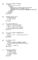
続いて、図7は、本実施例に係るデータ型であるOSDConfiguration型の構成を説明するための図である。ここで、図7に示すデータ型は、本実施例に係る、画像重畳設定リスト取得要求、画像重畳設定取得要求、画像重畳設定変更、及び画像重畳設定削除のトランザクションで使用される。 Next, FIG. 7 is a diagram for explaining the configuration of the OSDConfiguration type that is a data type according to the present embodiment. Here, the data type shown in FIG. 7 is used in an image superimposition setting list acquisition request, an image superimposition setting acquisition request, an image superimposition setting change, and an image superimposition setting deletion transaction according to this embodiment.
なお、図7に示すデータ型は、例えば、XML Schema Definition言語(以下XSDと称することがある)を用いて定義されるものとする。 The data type shown in FIG. 7 is defined using, for example, the XML Schema Definition language (hereinafter sometimes referred to as XSD).
図7(a)は、OSDConfiguration型の定義例を示す図である。図7(a)に示すように、OSDConfiguration型は、XMLのcomplexType宣言により、複雑型として定義される。 FIG. 7A is a diagram illustrating a definition example of the OSDConfiguration type. As shown in FIG. 7A, the OSDConfiguration type is defined as a complex type by an XML complexType declaration.
また、当該のOSDConfiguration型は、complexContent要素、及び、extension要素とそのbase属性によって、DeviceEntity型を拡張した拡張型であることが示される。なお、当該OSDConfiguration型は、sequence要素により、その順番が定義通りに出現するデータ拡張が行われていることが示される。 In addition, the OSDConfiguration type is an extended type obtained by extending the DeviceEntity type by the complexContent element, the extension element, and its base attribute. In the OSDConfiguration type, the sequence element indicates that data expansion in which the order appears as defined is performed.
図7(b)は、OSDRefernece型の定義例を示す図である。OSDReference型のデータにおいては、simpleContent要素、及び、extension要素とそのbase属性によって、ReferenceToken型を拡張した拡張型であることが示される。 FIG. 7B is a diagram illustrating a definition example of the OSDReference type. In the OSDReference type data, the SimpleContent element, the extension element, and its base attribute indicate that it is an extended type that is an extension of the ReferenceToken type.
図7(c)は、OSDType型の定義例を示す図である。OSDType型の定義例においては、simpleType要素によりXMLの単純型であるとともに、restriction要素とそのbase属性により、当該型がstring型の値制限型であることが示される。図7(c)の例では、OSDType型は、その値としてTextまたはImageもしくはExtendedであることが示されている。 FIG. 7C is a diagram illustrating a definition example of the OSDType type. In the definition example of the OSDType type, the simpleType element is an XML simple type, and the restriction element and its base attribute indicate that the type is a string type value limit type. In the example of FIG. 7C, it is indicated that the OSDType type is Text, Image, or Extended as its value.
図7(d)は、OSDPosConfiguration型の定義例を示す図である。当該OSDPosConfiguration型の定義例においては、complexType要素によって、当該型が複雑型として定義されることが示される。また、sequence要素により、その順番が定義通りに出現するデータ型であることが示される。 FIG. 7D is a diagram illustrating a definition example of the OSDPosConfiguration type. In the definition example of the OSDPosConfiguration type, the complexType element indicates that the type is defined as a complex type. In addition, the sequence element indicates that the data type appears in the order as defined.
図7(e)は、OSDTextConfiguration型の定義例を示す図である。当該OSDTextConfiguration型の定義例においては、complexType要素によって、当該型が複雑型として定義されることが示される。また、sequence要素により、その順番が定義通りに出現するデータ型であることが示される。 FIG. 7E is a diagram illustrating a definition example of the OSDTextConfiguration type. In the definition example of the OSDTextConfiguration type, the complexType element indicates that the type is defined as a complex type. In addition, the sequence element indicates that the data type appears in the order as defined.
図7(f)は、OSDImgConfiguration型を示す図である。当該のOSDImgConfiguration型の定義例においては、complexType要素によって、当該型が複雑型として定義されることが示される。また、sequence要素により、その順番が定義通りに出現するデータ型であることが示される。 FIG. 7F shows the OSDImgConfiguration type. In the definition example of the OSDImgConfiguration type, the complexType element indicates that the type is defined as a complex type. In addition, the sequence element indicates that the data type appears in the order as defined.
図7(g)は、OSDConfigurationExtension型の定義例を示す図である。当該OSDConfigurationExtension型の定義例においては、complexType要素によって、当該型が複雑型として定義されることが示される。また、sequence要素により、その順番が定義通りに出現するデータ型であることが示される。 FIG. 7G is a diagram illustrating a definition example of the OSDConfigurationExtension type. In the definition example of the OSDConfigurationExtension type, the complexType element indicates that the type is defined as a complex type. In addition, the sequence element indicates that the data type appears in the order as defined.
図7(h)は、OSDColor型の定義例を示す図である。OSDColor型の定義例においては、complexType要素によって、当該型が複雑型として定義されることが示される。また、sequence要素により、その順番が定義通りに出現するデータ型であることが示される。 FIG. 7H is a diagram illustrating a definition example of the OSDColor type. In the definition example of the OSDColor type, the complexType element indicates that the type is defined as a complex type. In addition, the sequence element indicates that the data type appears in the order as defined.
図7(i)は、Color型の定義例を示す図である。当該のColor型では、attribute要素により、float型の属性X、Y、および、Zを記述することができる構成となっている。また、上記属性X、Y、および、Zは、use=“required”指定により、当該Color型において必須の構成であることが示される。また、当該のColor型では、attribute要素により、anyURI型の属性Colorspaceを記述可能な構成となっている。 FIG. 7I is a diagram illustrating a definition example of the Color type. The color type has a configuration in which the float type attributes X, Y, and Z can be described by the attribute element. Also, the attributes X, Y, and Z indicate that they are indispensable components in the color type by specifying use = “required”. In addition, the color type has a configuration in which an anyURI type attribute Colorspace can be described by an attribute element.
続いて、図8は、本実施例に係るデータ型であるVideoSourceConfiguration型の定義例を説明するための図である。ここで、図8に示すデータ型は、本実施例に係る、画像処理設定リスト取得、画像処理設定追加要求、画像処理設定変更のトランザクションで使用される。なお、図8に示すデータ型は、図7と同様、XSDを用いて定義されるものとする。 Next, FIG. 8 is a diagram for explaining a definition example of the VideoSourceConfiguration type that is a data type according to the present embodiment. Here, the data type shown in FIG. 8 is used in an image processing setting list acquisition, an image processing setting addition request, and an image processing setting change transaction according to this embodiment. Note that the data types shown in FIG. 8 are defined using XSD, as in FIG.
図8(a)は、VideoSourceConfiguration型の定義例を示す図である。VideoSourceConfiguration型においては、complexType要素によって、当該型が複雑型として定義されることが示される。 FIG. 8A is a diagram illustrating a definition example of the VideoSourceConfiguration type. In the VideoSourceConfiguration type, the complexType element indicates that the type is defined as a complex type.
また、当該のVideoSourceConfiguration型は、complexContent要素、及び、extension要素とそのbase属性によって、ConfigurationEntity型を拡張した拡張型であることが示される。また、sequence要素により、その順番が定義通りに出現するデータ型であることが示される。 In addition, the VideoSourceConfiguration type is an extended type that is an extension of the ConfigurationEntity type by the complexContent element, the extension element, and its base attribute. In addition, the sequence element indicates that the data type appears in the order as defined.
図8(b)は、ReferenceToken型の定義例を示すである。ReferenceToken型においては、simpleType要素によりXMLの単純型であるとともに、restriction要素とそのbase属性により、当該型がstring型の値制限型であることが示される。 FIG. 8B shows a definition example of the ReferenceToken type. In the ReferenceToken type, the simpleType element is an XML simple type, and the restriction element and its base attribute indicate that the type is a string type value-restricted type.
図8(c)は、IntRectangle型の定義例を示す図である。IntRectangle型においては、attribute要素により、int型の属性x、y、width、及び、heightを記述することができる構成となっている。また、上記属性x、y、width、及び、heightは、use=“resuired”指定により、当該IntRectangle型において必須の構成であることが示される。 FIG. 8C is a diagram illustrating a definition example of the IntRectangle type. In the IntRectangle type, an int type attribute x, y, width, and height can be described by an attribute element. Further, the attributes x, y, width, and height indicate that they are indispensable components in the IntRectangle type by specifying use = “required”.
図8(d)は、VideoSourceConfigurationExtension型の定義例を示す図である。VideoSourceConfigurationExtension型においては、complexType要素によって、当該型が複雑型として定義されることが示される。また、sequence要素により、その順番が定義通りに出現するデータ型であることが示される。 FIG. 8D is a diagram illustrating a definition example of the VideoSourceConfigurationExtension type. In the VideoSourceConfigurationExtension type, the complexType element indicates that the type is defined as a complex type. In addition, the sequence element indicates that the data type appears in the order as defined.
図8(e)は、Rotate型の定義例を示す図である。Rotate型においては、complexType要素によって、当該型が複雑型として定義されることが示される。また、sequence要素により、その順番が定義通りに出現するデータ型であることが示される。 FIG. 8E is a diagram illustrating a definition example of the Rotate type. In the Rotate type, the complexType element indicates that the type is defined as a complex type. In addition, the sequence element indicates that the data type appears in the order as defined.
図8(f)は、RotateMode型の定義例を示す図である。RotateMode型においては、simpleType要素によりXMLの単純型であるとともに、restriction要素とそのbase属性により、当該型がstring型の値制限型であることが示される。図8(f)の例では、RotateMode型は、その値としてOFFまたはONもしくはAUTOであることが示されている。 FIG. 8F is a diagram illustrating a definition example of the RotateMode type. In the RotateMode type, the simpleType element indicates an XML simple type, and the restriction element and its base attribute indicate that the type is a string type value limit type. In the example of FIG. 8F, the RotateMode type is indicated as OFF, ON, or AUTO as its value.
続いて、図9及び図10は、本実施例に係るデータ型であるMetadataStream型の定義例を説明するための図である。ここで、図9及び図10に示すデータ型は、画像処理部1003で検知された物体に関する物体検知データ、及び画像処理部1003で物体が検知されたことを示すために配信されるイベントで使用される。このイベントは、監視カメラ1000からクライアント装置2000に配信されるものである。
Next, FIGS. 9 and 10 are diagrams for explaining a definition example of the MetadataStream type that is a data type according to the present embodiment. Here, the data types shown in FIGS. 9 and 10 are used in object detection data related to an object detected by the
なお、図9及び図10に示すデータ型は、図7と同様、XSDを用いて定義されるものとする。 The data types shown in FIGS. 9 and 10 are defined using XSD as in FIG.
図9(a)は、MetadataStream型の定義例を示す図である。MetadataStream型においては、complexType要素によって、当該型が複雑型として定義されることが示される。また、sequence要素により、その順番が定義通りに出現するデータ型であることが示される。 FIG. 9A is a diagram illustrating a definition example of MetadataStream type. In the MetadataStream type, the complexType element indicates that the type is defined as a complex type. In addition, the sequence element indicates that the data type appears in the order as defined.
また、sequence要素内部のchoice要素によって、当該choice要素内の一つが選択されることが示される。具体的には、当該MetadataStream型においては、後述するVideoAnalytics、PTZ、Eventフィールド、または、Extensionフィールドから一つが選択される。 Further, it is indicated that one of the choice elements is selected by the choice element inside the sequence element. Specifically, in the MetadataStream type, one is selected from a VideoAnalytics, a PTZ, an Event field, or an Extension field, which will be described later.
図9(b)は、VideoAnalyticsStream型の定義例を示すである。VideoAnalyticsStream型においてはcomplexType要素によって、当該型が複雑型として定義されることが示される。また、sequence要素により、その順番が定義通りに出現するデータ型であることが示される。 FIG. 9B shows a definition example of the VideoAnalytics Stream type. In the VideoAnalyticsStream type, the complexType element indicates that the type is defined as a complex type. In addition, the sequence element indicates that the data type appears in the order as defined.
図9(c)は、PTZStream型の定義例を示す図である。PTZStream型においては、complexType要素によって、当該型が複雑型として定義されることが示される。また、sequence要素により、その順番が定義通りに出現するデータ型であることが示される。 FIG. 9C is a diagram illustrating a definition example of the PTZStream type. In the PTZStream type, the complexType element indicates that the type is defined as a complex type. In addition, the sequence element indicates that the data type appears in the order as defined.
また、sequence要素内部のchoice要素によって、当該choice要素内の一つが選択されることが示される。具体的には、当該PTZStream型においては、PTZStatusフィールド、または、Extensionフィールドから一つが選択される。 Further, it is indicated that one of the choice elements is selected by the choice element inside the sequence element. Specifically, in the PTZStream type, one is selected from the PTZStatus field or the Extension field.
図9(d)は、EventStream型の定義例を示す図である。EventStream型においては、complexType要素によって、当該型が複雑型として定義されることが示される。また、sequence要素により、その順番が定義通りに出現するデータ型であることが示される。また、sequence要素内部のchoice要素によって、当該choice要素内の一つが選択されることが示される。 FIG. 9D is a diagram illustrating a definition example of the EventStream type. In the EventStream type, the complexType element indicates that the type is defined as a complex type. In addition, the sequence element indicates that the data type appears in the order as defined. Further, it is indicated that one of the choice elements is selected by the choice element inside the sequence element.
具体的には、当該EventStream型においては、NotificationMessageフィールド、または、Extensionフィールドから一つが選択される。 Specifically, in the EventStream type, one is selected from the Notification Message field or the Extension field.
図9(e)は、MetadataStreamExtension型の定義例を示す図である。MetadataStreamExtension型においては、complexType要素によって、当該型が複雑型として定義されることが示される。また、sequence要素により、その順番が定義通りに出現するデータ型であることが示される。 FIG. 9E is a diagram illustrating a definition example of the MetadataStreamExtension type. In the MetadataStreamExtension type, the complexType element indicates that the type is defined as a complex type. In addition, the sequence element indicates that the data type appears in the order as defined.
続いて、図10(a)は、Frame型の定義例を示す図である。Frame型においては、complexType要素によって、当該型が複雑型として定義されることが示される。また、sequence要素により、その順番が定義通りに出現するデータ型であることが示される。 Subsequently, FIG. 10A is a diagram illustrating a definition example of the Frame type. In the Frame type, the complexType element indicates that the type is defined as a complex type. In addition, the sequence element indicates that the data type appears in the order as defined.
図10(b)は、Object型の定義例を示す図である。Object型においては、complexType要素によって、当該型が複雑型として定義されることが示される。また、当該のObject型は、complexContent要素、及び、extension要素とそのbase属性によって、ObjectId型を拡張した拡張型であることが示される。 FIG. 10B is a diagram illustrating a definition example of the Object type. In the Object type, the complexType element indicates that the type is defined as a complex type. In addition, the Object type is an extension type obtained by extending the ObjectId type by the complexContent element, the extension element, and its base attribute.
また、当該Object型は、sequence要素により、その順番が定義通りに出現するデータ拡張が行われていることが示される。 In addition, the Object type indicates that the data expansion in which the order appears as defined is performed by the sequence element.
図10(c)は、Appearance型の定義例を示す図である。Appearance型においては、complexType要素によって、当該型が複雑型として定義されることが示される。また、sequence要素により、その順番が定義通りに出現するデータ型であることが示される。 FIG. 10C is a diagram illustrating a definition example of the Appearance type. In the Appearance type, the complexType element indicates that the type is defined as a complex type. In addition, the sequence element indicates that the data type appears in the order as defined.
図10(d)は、ShapeDescriptor型の定義例を示す図である。ShapeDescriptor型においては、complexType要素によって、当該型が複雑型として定義されることが示される。また、sequence要素により、その順番が定義通りに出現するデータ型であることが示される。 FIG. 10D is a diagram illustrating a definition example of the ShapeDescriptor type. In the ShapeDescriptor type, the complexType element indicates that the type is defined as a complex type. In addition, the sequence element indicates that the data type appears in the order as defined.
図10(e)は、Rectangle型の定義例を示す図である。Rectangle型においては、attribute要素により、float型の属性bottom、top、right、及び、leftを記述することができる構成となっている。また、上記属性bottom、top、right、及び、leftは、use=“resuired”指定により、当該Rectangle型において必須の構成であることが示される。 FIG. 10E is a diagram illustrating a definition example of a rectangle type. In the Rectangle type, the float type attributes bottom, top, right, and left can be described by the attribute element. Further, the attributes bottom, top, right, and left indicate that they are indispensable configurations in the Rectangle type by specifying use = “required”.
図10(f)は、Vector型の定義例を示す図である。Vector型においては、attribute要素により、float型の属性x、及び、yを記述することができる構成となっている。また、上記属性x、及び、yは、use=“resuired”指定により、当該Rectangle型において必須の構成であることが示される。 FIG. 10F is a diagram illustrating a definition example of the Vector type. In the Vector type, a float type attribute x and y can be described by the attribute element. Further, the attributes x and y indicate that the structure is indispensable in the Rectangle type by specifying use = “required”.
続いて、図11は、SetVideoSourceConfiguration受信処理を説明するためのフローチャートである。この処理により、VideoSourceConfigurationの設定値がOSD画像の設定に反映される。 Next, FIG. 11 is a flowchart for explaining the SetVideoSourceConfiguration reception process. By this processing, the setting value of VideoSourceConfiguration is reflected in the setting of the OSD image.
なお、この処理は、制御部1008により実行される。又、このSetVideoSourceConfigurationsのコマンドは、画像処理設定変更のコマンドに相当する(即ち、このコマンドは、撮像画像を回転させるための回転命令に相当する)。
This process is executed by the
ここで、制御部1008は、SetVideoSourceConfigurationsのコマンドをクライアント装置2000から受信した場合に、図11の処理を開始する。
Here, the
具体的には、制御部1008は、このコマンドをクライアント装置2000から受信した場合に、記憶部1009に記憶された複数のOSD設定情報のうち、1つのOSD設定情報を選択する。この選択の後、制御部1008は、次のようなOSD画像描画処理を開始する。即ち、図11の処理を開始し、この処理の終了の後、OSD生成部1007に指示し、後述の図15の処理を開始させる処理である。
Specifically, when this command is received from the
そして、制御部1008は、このOSD画像描画処理の終了後、記憶部1009に記憶された複数のOSD設定情報のうち、新たなOSD設定情報を1つ選択する。この選択の後、上述のOSD画像描画処理を開始する。制御部1008は、このような一連の処理を、記憶部1009に記憶された複数のOSD設定情報を全て選択するまで、繰り返す。
Then, after the OSD image drawing process is completed, the
ステップS4001では、制御部1008は、重畳モード判定処理を実行する。この重畳モード判定処理は、制御部1008により選択されたOSD設定情報(OSDConfiguration)が第一の重畳モードを示すのか、それとも第二の重畳モードを示すのかを判定するための処理である。
In step S4001, the
ここで、第一の重畳モードとは、監視カメラ1000から配信される配信画像が回転した場合に、この配信画像の表示画面上における、OSD画像の位置を変えないモードである。そして、換言すれば、第一の重畳モードとは、後述の正規化座標系におけるOSD画像の位置を変えないモードである。なお、この正規化座標系の水平方向及び垂直方向は、この配信画像が回転するか否かに係らず、不変である。
Here, the first superposition mode is a mode in which the position of the OSD image on the display screen of the distribution image is not changed when the distribution image distributed from the
また、換言すれば、第一の重畳モードとは、監視カメラ1000から配信される配信画像が回転した場合に、この配信画像に含まれる被写体に対し、OSD画像の位置を変えるモードである(つまり、第一の重畳モードとは、この配信画像に含まれる被写体の変化に伴って、この配信画像におけるOSD画像の重畳位置を変化させないモードである)。
In other words, the first superposition mode is a mode in which the position of the OSD image is changed with respect to the subject included in the distribution image when the distribution image distributed from the
更に、換言すれば、第一の重畳モードとは、監視カメラ1000が撮像可能な全範囲における、OSD画像の位置を変えるモードである。なお、この第一の重畳モードで重畳されるOSD画像は、後述の固定OSD画像5006に対応する。
Furthermore, in other words, the first superposition mode is a mode for changing the position of the OSD image in the entire range that can be imaged by the
ここで、第二の重畳モードとは、監視カメラ1000から配信される配信画像が回転した場合に、この配信画像の表示画面上における、OSD画像の位置を変えるモードである。そして、換言すれば、第二の重畳モードとは、第二の重畳モードとは、後述の正規化座標系におけるOSD画像の位置を変えるモードである。
Here, the second superposition mode is a mode for changing the position of the OSD image on the display screen of the distribution image when the distribution image distributed from the
また、換言すれば、第二の重畳モードとは、監視カメラ1000から配信される配信画像が回転した場合に、この配信画像に含まれる被写体に対し、OSD画像の位置を変えないモードである(つまり、第二の重畳モードとは、この配信画像に含まれる被写体の変化に伴って、この配信画像におけるOSD画像の重畳位置を変化させるモードである)。
In other words, the second superposition mode is a mode in which the position of the OSD image is not changed with respect to the subject included in the distribution image when the distribution image distributed from the
更に、換言すれば、第二の重畳モードとは、監視カメラ1000が撮影可能な全範囲における、OSD画像の位置を変えないモードである。なお、第二の重畳モードで重畳されるOSD画像は、後述のフローティングOSD画像5005に対応する。
Furthermore, in other words, the second superposition mode is a mode in which the position of the OSD image is not changed in the entire range that can be photographed by the
ステップS4002では、制御部1008は、ステップS4001にてOSDConfigurationが第一の重畳モードを示すと判定された場合には、ステップS4003に処理を進める。一方、制御部1008は、ステップS4001にてOSDConfigurationが第二の重畳モードを示すと判定された場合には、ステップS4006に処理を進める。
In step S4002, if it is determined in step S4001 that the OSDConfiguration indicates the first superposition mode, the
ステップS4003では、制御部1008は、後述の固定OSD設定処理を実行する。この処理の実行の後、制御部1008は、ステップS4004に処理を進める。
In step S4003, the
ステップS4004では、制御部1008は、制御部1008により選択されたOSDConfigurationをOSDTokenと共に記憶部1009に保存する。
In step S4004, the
ステップS4005では、制御部1008は、レスポンス送信処理を実行する。この処理は、SetVideoSourceConfigurationsコマンドに対するレスポンスをクライアント装置2000に送信するための処理である。
In step S4005, the
ステップS4006では、制御部1008は、後述のフローティングOSD設定処理を実行する。この処理の実行の後、制御部1008は、ステップS4005に処理を進める。
In step S4006, the
続いて、図12は、図11のステップS4001における重畳モード判定処理の詳細を説明するためのフローチャートである。なお、この処理は、制御部1008により実行されるものとする。
Next, FIG. 12 is a flowchart for explaining details of the superposition mode determination processing in step S4001 of FIG. Note that this processing is executed by the
ステップS4101では、制御部1008は、制御部1008に選択されたOSD設定情報を設定するためのパラメータに、OSD画像(重畳情報)として文字情報を重畳することを示すパラメータが含まれるか否かを判定する。具体的には、まず、制御部1008は、制御部1008で選択されたOSDConfigurationに含まれるOSDTypeの値がTEXTであるか否かを判定する。
In step S4101, the
ここで、制御部1008は、このOSDTypeの値がTEXTであると判定した場合には、制御部1008で選択されたOSD設定情報を設定するためのパラメータに、OSD画像として文字情報を重畳することを示すパラメータが含まれると判定する。
If the
一方、制御部1008は、このOSDTypeの値がTEXTではないと判定した場合には、制御部1008で選択されたOSD設定情報を設定するためのパラメータに、OSD画像として文字情報を重畳することを示すパラメータが含まれていないと判定する。
On the other hand, when the
そして、制御部1008は、制御部1008で選択されたOSD設定情報を設定するためのパラメータに、OSD画像として文字情報を重畳することを示すパラメータが含まれると判定した場合には、ステップS4102に処理を進める。
If the
一方、制御部1008は、制御部1008で選択されたOSD設定情報を設定するためのパラメータに、OSD画像として文字情報を重畳することを示すパラメータが含まれていないと判定した場合には、ステップS4105に処理を進める。
On the other hand, if the
ステップS4102では、制御部1008は、OSD画像(重畳情報)として指定されている文字列が所定の指定文字列であるか否かを判定する。この文字列は、OSD画像として重畳する文字情報の種別を指定するためのパラメータとして機能する。
In step S4102, the
そして、制御部1008は、OSD画像が指定文字列であると判定した場合には、ステップS4103に処理を進める。一方、制御部1008は、OSD画像が指定文字列ではないと判定した場合には、ステップS4105に処理を進める。
If the
なお、本実施例において、指定文字列である場合とは、OSDConfigurationが含むOSDTextConfigurationに含まれるPlainTextの値が空白である場合のことを指すが、これに限られない。 In the present embodiment, the case of the designated character string indicates a case where the value of PlainText included in the OSDTextConfiguration included in the OSDConfiguration is blank, but is not limited thereto.
例えば、OSDTextConfigurationが以下のような他の条件を満たす場合であってもよい。すなわち、指定文字列である場合とは、OSDType=TEXT、且つOSDTextConfiguration.Type=PLAINで、PlainTextが空白であった場合とすることができる。 For example, it may be a case where OSDTextConfiguration satisfies the following other conditions. That is, the case of the designated character string means that OSDType = TEXT and OSDTextConfiguration. It can be assumed that Type = PLAIN and PlainText is blank.
あるいは、指定文字列とは、PlainTextに、重畳モードが第1の重畳モードであることを示す制御コード、例えば「#FLOATING」等が指定されていた場合としてもよい。 Alternatively, the designated character string may be a case where a control code indicating that the superposition mode is the first superposition mode, such as “#FLOATING”, is designated in PlainText.
ステップS4103では、制御部1008は、OSD画像における背景色が設定されているか否かを判定する。具体的には、まず、制御部1008は、OSDConfigurationが含むOSDTextConfigurationにBackgroundColorが含まれているか否かを判定する。
In step S4103, the
ここで、制御部1008は、OSDConfigurationが含むOSDTextConfigurationにBackgroundColorが含まれていると判定した場合には、OSD画像における背景色が設定されていると判定する。
Here, if the
一方、制御部1008は、OSDConfigurationが含むOSDTextConfigurationにBackgroundColorが含まれていないと判定した場合には、OSD画像における背景色が設定されていないと判定する。
On the other hand, when the
そして、制御部1008は、OSD画像における背景色が設定されていると判定した場合には、ステップS4104に処理を進める。一方、制御部1008は、OSD画像における背景色が設定されていないと判定した場合には、ステップS4105に処理を進める。
If the
ステップS4104では、制御部1008は、制御部1008で選択されたOSDConfigurationが第二の重畳モードを示すと判定し、この第二の重畳モードである旨を出力する。
In step S4104, the
ステップS4105では、制御部1008は、制御部1008で選択されたOSDConfigurationが第一の重畳モードを示すと判定し、この第一の重畳モードである旨を出力する。
In step S4105, the
続いて、図13は、図11のステップS4003における固定OSD設定処理の詳細を説明するためのフローチャートである。なお、この処理は、制御部1008により実行されるものとする。
Subsequently, FIG. 13 is a flowchart for explaining details of the fixed OSD setting process in step S4003 of FIG. Note that this processing is executed by the
ステップS4201では、制御部1008は、制御部1008で選択されたOSDConfigurationに含まれるOSD画像の位置情報(即ち、OSDPosConfigurationの設定内容)を、OSD生成部1007に入力する。
In step S4201, the
ステップS4202では、制御部1008は、後述のOSD種別に合わせ、OSDTextConfiguration、或いはOSDImgConfigurationの内容をOSD生成部1007へ入力する。なお、このOSD種別は、ステップS4001で判定され亜OSDConfigurationに含まれるものである。より詳細には、このOSD種別は、即ち、OSDTypeの内容である。
In step S4202, the
ステップS4203では、制御部1008は、OSD生成部1007の位置情報アップデート機能をOFFに設定する。即ち、制御部1008は、OSD生成部1007の重畳モードを、配信画像5002に対し、OSD画像の重畳位置及び重畳サイズが固定されるモードに設定する。
In step S4203, the
ステップS4204では、制御部1008は、OSD生成部1007の、OSD有効フラグをONに設定する。これにより、配信画像5002に対するOSD画像の重畳処理が開始される。
In step S4204, the
続いて、図14は、図11のステップS4006におけるフローティングOSD設定処理の詳細を説明するためのフローチャートである。なお、この処理は、制御部1008により実行されるものとする。
Next, FIG. 14 is a flowchart for explaining details of the floating OSD setting process in step S4006 of FIG. Note that this processing is executed by the
ステップS4301乃至S4302は、上述のステップS4201乃至S4202と同様であるので、その説明を省略する。 Since steps S4301 to S4302 are the same as steps S4201 to S4202 described above, description thereof is omitted.
ステップS4303では、制御部1008は、OSD生成部1007の位置情報アップデート機能をONに設定する。
In step S4303, the
即ち、制御部1008は、OSD生成部1007の重畳モードを、監視カメラ1000が撮像可能な全範囲に対し、OSD画像の重畳位置及び重畳サイズが固定されるモードに設定する。これにより、このモードでは、配信画像5002に対し、重畳情報の重畳位置及び重畳サイズは、必ずしも固定されない。
That is, the
ステップS4304は、上述のステップS4204と同様であるので、その説明を省略する。 Since step S4304 is the same as step S4204 described above, description thereof is omitted.
続いて、図15は、OSD位置情報アップデート処理を説明するためのフローチャートである。本処理は、OSD生成部1007に含まれる、制御部1008とは独立したプロセッサに実行させる処理として説明する。OSD生成部1007がプロセッサを内蔵する形態では、図15の処理フローは、図12に示す手順をOSD生成部1007のプロセッサに実行させるためのプログラムを示す。
Next, FIG. 15 is a flowchart for explaining the OSD position information update process. This processing will be described as processing executed by a processor included in the
なお、OSD生成部1007が内蔵するプロセッサはコンピュータであり、監視カメラ1000が内蔵する記憶部1009から読み出したプログラムを実行する。
Note that the processor built in the
あるいは、制御部1008がOSD位置情報アップデート処理を実行してもよい。監視カメラ1000の制御部1008がプロセッサを内蔵する形態では、図15の処理フローは、図15に示す手順を制御部1008に実行させるためのプログラムを示す。監視カメラ1000の制御部1008が内蔵するプロセッサはコンピュータであり、監視カメラ1000が内蔵する記憶部1009から読み出したプログラムを実行する。
Alternatively, the
ステップS4401では、OSD生成部1007は、位置情報アップデート機能がONであるか否かを判定する。そして、OSD生成部1007は、位置情報アップデート機能がONであると判定した場合には、ステップS4402に処理を進める。一方、OSD生成部1007は、位置情報アップデート機能がONではないと判定した場合には、図15に示す処理を終了する。
In step S4401, the
ステップS4402では、OSD生成部1007は、画像処理部1003が撮像部1002から出力された撮像画像をローテート(回転)させているか否かを判定する。ここで、OSD生成部1007は、クライアント装置2000から受信したSetVideoSourceConfigurationsコマンドに含まれる撮像画像を回転させる設定、及び撮像画像を回転させる角度に基づき、この判定を行う。
In step S4402, the
そして、OSD生成部1007は、画像処理部1003が撮像部1002から出力された撮像画像を回転させていると判定した場合には、ステップS4403に処理を進める。例えば、図17における配信画像5002から図18における配信画像5002に変化した場合には、OSD生成部1007は、ステップS4403に処理を進める。
If the
一方、OSD生成部1007は、画像処理部1003が撮像部1002から出力された撮像画像を回転させていないと判定した場合には、本処理を終了する。
On the other hand, if the
ステップS4403では、OSD生成部1007は、撮像部1002から出力された撮像画像を画像処理部1003が回転させた角度に基づき、ステップS4303で位置情報アップデート機能がONにされたOSD画像の重畳位置及び重畳サイズを更新する。
In step S4403, the
具体的には、OSD生成部1007は、この角度に基づき、このOSD画像の重畳位置及び重畳サイズが、監視カメラ1000が撮影可能な全範囲に対して同一となるよう、この重畳位置及び重畳サイズを再計算する。そして、OSD生成部1007は、再計算した重畳位置及び重畳サイズで重畳されるよう、OSD画像を出力する。
Specifically, based on this angle, the
続いて、図16乃至18を用いて、監視カメラ1000からストリーミング配信される撮像画像の一例を説明する。より詳細には、図16乃至18のそれぞれは、監視カメラ100における、OSD画像の重畳位置と座標との関係を示す。
Next, an example of a captured image that is streamed from the
図16において、パン範囲5010は、アーム機構1102のパン方向の全可動範囲を示す。又、チルト範囲5011は、アーム機構1102のチルト方向の全稼働範囲を示す。撮像可能範囲5000は、アーム機構1102が駆動されることにより、撮像部1002が撮像可能な全範囲を示す。
In FIG. 16, a
撮像画像5001は、あるズーム倍率において、撮像部1002から出力される撮像画像を示す。又、5012は、撮像画像5001の水平方向の範囲である。そして、5013は、撮像画像5001の垂直方向の範囲である。更に、配信画像5002は、VideoSourceConfigurationに含まれるBoundsにより指定された配信画像である。
A captured
このBoundsは、撮像画像5001から配信画像5002を切り出すための切り出し位置として、配信画像5002の左下の頂点5003をピクセルで指定するための、水平方向位置(x)及び垂直方向位置(y)を含む。この頂点5003は、このBoundsが示す座標の原点に相当するものである。
This Bounds includes a horizontal position (x) and a vertical position (y) for designating the lower left
又、このBoundsは、配信画像5002のサイズをピクセルで指定するための、水平方向サイズ(Width)5014及び垂直方向サイズ(Height)5015のパラメータを含む。
The Bounds includes parameters of a horizontal size (Width) 5014 and a vertical size (Height) 5015 for specifying the size of the
被写体5004は、配信画像5002内の被写体である。本実施例において、被写体5004の位置は、Boundsによって切り出された配信画像5002における左上の頂点を原点とするブロック座標系により示される。このブロック座標系は、水平方向(x)に60分割され、且つ垂直方向(y)に32分割されている。
A subject 5004 is a subject in the
このブロック座標系により示された被写体5004の位置は、MetadataStream型(図9(a))のデータが含むShapeDescriptor型(図10(d))のデータにより、監視カメラ1000からクライアント装置2000に通知される。
The position of the subject 5004 indicated by the block coordinate system is notified from the
より詳細には、このブロック座標系により示された被写体5004の位置は、このShapeDescriptor型のデータに含まれる、BoundingBox及びCenterOfGravityにより、クライアント装置2000へ通知される。
More specifically, the position of the subject 5004 indicated by this block coordinate system is notified to the
図16の例では、被写体5004の範囲は、配信画像5002において、BoundingBox(left、right、top、bottom)=(40.0、44.0、17.0、21.0)と指定されている。又、被写体5004の位置は、配信画像5002において、CenterOfGravity(x、y)=(42.0、20.0)と指定されている。
In the example of FIG. 16, the range of the subject 5004 is specified as “BoundingBox (left, right, top, bottom)” = (40.0, 44.0, 17.0, 21.0) in the
続いて、図17における5005は、図7(a)のOSDConfiguration型のデータによって指定されるOSD画像である。このOSD画像は、上述のフローティングOSD画像に相当するものである。又、5006は、図7(a)のOSDConfiguration型のデータによって指定されるOSD画像である。このOSD画像は、上述の固定OSD画像に相当するものである。
Subsequently,
なお、本実施例では、固定OSD画像5006に含まれる文字は、撮像部1002が被写体を撮像した日付であるものとする。また、本実施例では、フローティングOSD画像5005は、撮像部1002から出力された撮像画像に含まれる所定領域を覆うためのプライバシーマスク画像に相当する。
In this embodiment, it is assumed that the character included in the fixed
本実施例では、フローティングOSD画像5005、及び固定OSD画像5006の位置は、図7(d)のOSDPosConfiguration型のデータによって指定される。
In this embodiment, the positions of the floating
より詳細には、このデータは、フローティングOSD画像5005及び固定OSD画像5006の中心点を、Boundsで切り出された配信画像5002内を水平方向(x)及び垂直方向(y)ともに−1.0〜+1.0に正規化された正規化座標系で指定する。なお、本実施例における記憶部1009は、この正規化座標系を示す情報を保持する保持部としての機能を持つものとする。
More specifically, this data includes the center point of the floating
図17の例では、フローティングOSD画像5005の中心点は、配信画像5002において、(x,y)=(0.4,−0.1)と指定されている。この中心点は、フローティングOSD画像5005が配信画像5002に重畳される位置に相当する。
In the example of FIG. 17, the center point of the floating
また、図17の例では、固定OSD画像5006の中心点は、配信画像5002において、(x,y)=(0.8,−0.9)と指定されている。この中心点は、固定OSD画像5006が配信画像5002に重畳される位置に相当する。
In the example of FIG. 17, the center point of the fixed
続いて、図18は、図17で示した配信画像5002が時計回りに90度回転させられた場合における、配信画像5002を説明するための図である。より詳細には、図18は、この90度回転させられた場合における、被写体5004、フローティングOSD画像5005及び固定OSD画像5006の位置を説明するための図である。
Next, FIG. 18 is a diagram for explaining the
なお、この90度回転は、VideoSourceConfigurationsのコマンドをクライアント装置2000が用いる(送信する)ことにより、行われる。
The 90-degree rotation is performed when the
図18において、配信画像5002における被写体5004の範囲及び位置は、配信画像5002が時計回りに90度回転したことにより、再計算される。図18の例では、被写体5004の範囲は、配信画像5002において、BoundingBox(left、right、top、bottom)=(13.0、17.0、40.0、44.0)と指定されている。
In FIG. 18, the range and position of the subject 5004 in the
又、図18の例では、被写体5004の位置は、配信画像5002において、CenterOfGravity(x、y)=(15.0、42.0)と指定されている。
In the example of FIG. 18, the position of the subject 5004 is designated as CenterOfGravity (x, y) = (15.0, 42.0) in the
フローティングOSD画像5005の位置であって、図7(d)のOSDPosConfiguration型のデータによって指定される位置は、図17におけるこの位置と同じ位置に保たれない。これは、配信画像5002が時計回りに90度回転したことにより、この位置が移動したためである。
The position of the floating
図18の例では、フローティングOSD画像5005の位置であって、図7(d)のOSDPosConfiguration型のデータによって指定される位置は、配信画像5002において、(x,y)=(−0.1、−0.4)と指定される。
In the example of FIG. 18, the position of the floating
一方、固定OSD画像5006の位置であって、図7(d)のOSDPosConfiguration型のデータによって指定される位置は、図17におけるこの位置と同じ位置に保たれる。これは、配信画像5002が時計回りに90度回転しても、この位置が移動しないからである。
On the other hand, the position of the fixed
続いて、図19は、配信画像5002において検知された物体に関する物体情報などを含むMetadataStreamの構成の一例を示す。このMetadataStreamは、監視カメラ1000からクライアント装置2000に送信される。
Next, FIG. 19 shows an example of the configuration of MetadataStream including object information related to an object detected in the
図19(a)におけるMetadataStreamは、図17の配信画像5002に対応するものである。このMetadataStreamにおいて、被写体5004の範囲は、BoundingBoxにより指定されている。具体的には、この範囲は、BoundingBox(left、right、top、bottom)=(40.0、44.0、17.0、21.0)と指定されている。
The MetadataStream in FIG. 19A corresponds to the
また、このMetadataStreamにおいて、被写体5004の位置は、CenterOfGravityにより指定されている。具体的には、この位置は、CenterOfGravity(x、y)=(42.0、20.0)と指定されている。 In this MetadataStream, the position of the subject 5004 is designated by CenterOfGravity. Specifically, this position is designated as CenterOfGravity (x, y) = (42.0, 20.0).
図19(b)におけるMetadataStreamは、図18の配信画像5002に対応するものである。このMetadataStreamにおいて、被写体5004の範囲は、BoundingBox(left、right、top、bottom)=(13.0、17.0、40.0、44.0)と指定されている。
The MetadataStream in FIG. 19B corresponds to the
また、このMetadataStreamにおいて、被写体5004の位置は、CenterOfGravity(x、y)=(15.0、42.0)と指定されている。 Further, in this MetadataStream, the position of the subject 5004 is designated as CenterOfGravity (x, y) = (15.0, 42.0).
続いて、図20は、配信画像5002に含まれるOSD画像に対応するOSD設定情報をクライアント装置2000に送信するための、GetOSDsレスポンスの構成の一例を示す。このGetOSDsレスポンスは、図7(a)のOSDConfiguration型のデータである。
Next, FIG. 20 shows an example of the configuration of a GetOSDs response for transmitting OSD setting information corresponding to the OSD image included in the
図20(a)は、図9(b)及び図9(c)の固定OSD画像5006に対応するGetOSDsレスポンスの構成を示す。このGetOSDsレスポンスにおいて、固定OSD画像5006の重畳位置は、Posフィールドによって、(x,y)=(0.8,−0.9)と指定されている。
FIG. 20A shows the structure of a GetOSDs response corresponding to the fixed
図20(b)は、図9(b)のフローティングOSD画像5005のGetOSDsレスポンスの構成を示す。このGetOSDsレスポンスにおいて、フローティングOSD画像5005の重畳位置は、Posフィールドによって、(x,y)=(0.4、−0.1)と指定されている。
FIG. 20B shows the structure of the GetOSDs response of the floating
図20(c)は、図9(c)のフローティングOSD画像5005のGetOSDsレスポンスの構成を示す。このGetOSDsレスポンスにおいて、フローティングOSD画像5005の重畳位置は、Posフィールドによって、(x,y)=(−0.1,−0.4)と指定されている。
FIG. 20C shows the structure of the GetOSDs response of the floating
以上のように、本実施例のOSD生成部1007は、配信画像5002が回転された際、OSDConfiguration型のデータに基づき、OSD画像の重畳位置を変更する。具体的には、OSD生成部1007は、このデータに基づき、図7(d)のOSDPosConfiguration型のデータで指定される位置であって、フローティングOSD画像5005の位置のみを変更し、固定OSD画像5006の位置は、変更しない。
As described above, when the
なお、この変更の際、OSD生成部1007が用いるデータは、OSDConfiguration型のデータが含むOSDType、OSDTextConfiguration型のデータが含むPlainText及びBackgroundColorである。
Note that the data used by the
これにより、監視カメラ1000から配信された配信画像5002が回転した場合、配信画像5002に重畳された複数のOSD画像のうち、特定のOSD画像のみを回転させることができる。この結果、例えば、配信画像5002が表示される表示画面上において、文字を含むOSD画像が回転してしまうことにより、このOSD画像の視認性が悪化することを防止することができる。
Thus, when the
また、本実施例における制御部1008は、配信画像5002が回転した場合、配信画像5002から検知された物体の位置を表すための座標系は回転させることなく、この座標系におけるこの物体の位置を回転させることができる。これにより、配信画像5002に含まれる被写体とこの検知された物体との位置関係に不整合が発生することを防止することができる。
In addition, when the
また、本発明は、以下の処理を実行することによっても実現される。即ち、上述した実施例の機能を実現するソフトウェア(プログラム)を、ネットワークまたは各種記憶媒体を介してシステムあるいは装置に供給し、そのシステムあるいは装置のコンピュータ(またはCPUやMPU等)がプログラムを読みだして実行する処理である。 The present invention can also be realized by executing the following processing. That is, software (program) for realizing the functions of the above-described embodiments is supplied to a system or apparatus via a network or various storage media, and the computer (or CPU, MPU, etc.) of the system or apparatus reads the program. To be executed.
以上、本発明の好ましい実施形態について説明したが、本発明はこれらの実施形態に限定されず、その要旨の範囲内で種々の変形及び変更が可能である。 As mentioned above, although preferable embodiment of this invention was described, this invention is not limited to these embodiment, A various deformation | transformation and change are possible within the range of the summary.
1000 監視カメラ
1002 撮像部
1004 圧縮符号化部
1005 通信部
1008 制御部
1500 IPネットワーク網
2000 クライアント装置
1000
Claims (8)
被写体を撮像するための撮像手段と、
前記撮像手段から出力された撮像画像を回転処理して得られる画像を配信画像として出力させるための命令を、前記外部装置からネットワークを介して受信する受信手段と、
前記受信手段によって前記命令が受信された場合に、重畳情報に対して設定されたフラグに従って、前記撮像手段から出力された撮像画像を回転処理して得られる配信画像に前記重畳情報を重畳させるように重畳手段を制御する制御手段とを有し、
前記制御手段は、前記重畳情報に対して設定されたフラグに従って、前記配信画像が表示画面上に表示されたときの所定の位置に重畳される第1の重畳情報として前記重畳情報を前記配信画像に重畳させるか、あるいは、前記回転処理に追従して重畳される第2の重畳情報として前記重畳情報を前記配信画像に重畳させるかを判定することを特徴とする撮像装置。 An imaging device capable of communicating with an external device via a network,
Imaging means for imaging a subject;
Receiving means for receiving an instruction for outputting an image obtained by rotating the captured image output from the imaging means as a distribution image from the external device via a network;
When the command is received by the receiving unit, the superimposition information is superimposed on a distribution image obtained by rotating the captured image output from the imaging unit according to a flag set for the superimposition information. Control means for controlling the superimposing means,
The control means uses the distribution information as first superimposition information to be superimposed at a predetermined position when the distribution image is displayed on a display screen according to a flag set for the superimposition information. An imaging apparatus for determining whether to superimpose the superimposition information on the distribution image as second superimposition information to be superimposed following the rotation process.
前記制御手段は、前記受信手段で回転命令が受信された場合に、前記保持部に保持された座標系を回転させることなく、前記撮像手段から出力された撮像画像、及び前記保持部に保持された座標系における、前記検知手段により検知された物体の位置を回転させることを特徴とする請求項1乃至請求項4のいずれか1項に記載の撮像装置。 Detection means for detecting an object from a captured image output from the imaging means, and holding means for holding a coordinate system for representing the position of the object detected by the detection means in a holding unit;
The control unit holds the captured image output from the imaging unit and the holding unit without rotating the coordinate system held by the holding unit when the receiving unit receives a rotation command. The imaging apparatus according to claim 1 , wherein the position of the object detected by the detection unit in a coordinate system is rotated.
前記外部装置は、
前記撮像部から出力された撮像画像を回転処理して得られる画像を配信画像として出力させるための命令を、前記撮像装置にネットワークを介して送信する送信手段、
を有し、
前記撮像装置は、
前記命令を、前記外部装置からネットワークを介して受信する受信手段と、前記受信手段によって前記命令が送信された場合に、重畳情報に対して設定されたフラグに従って、前記撮像部から出力された撮像画像を回転処理して得られる配信画像に前記重畳情報を重畳させるように重畳手段を制御する制御手段と、を有し、
前記制御手段は、前記重畳情報に対して設定されたフラグに従って、前記配信画像が表示画面上に表示されたときの所定の位置に重畳される第1の重畳情報として前記重畳情報を前記配信画像に重畳させるか、あるいは、前記回転処理に追従して重畳される第2の重畳情報として前記重畳情報を前記配信画像に重畳させるかを判定することを特徴とする撮像システム。 An imaging system that includes an external device and an imaging device that includes an imaging unit that images a subject and can communicate with the external device via a network,
The external device is
Transmitting means for transmitting a command for outputting an image obtained by rotating the captured image output from the imaging unit as a distribution image to the imaging device via a network;
Have
The imaging device
A receiving unit that receives the command from the external device via a network, and an imaging that is output from the imaging unit according to a flag set for superimposition information when the command is transmitted by the receiving unit Control means for controlling the superimposing means so as to superimpose the superposition information on a distribution image obtained by rotating the image,
The control means uses the distribution information as first superimposition information to be superimposed at a predetermined position when the distribution image is displayed on a display screen according to a flag set for the superimposition information. An imaging system for determining whether to superimpose the superimposition information on the distribution image as second superimposition information to be superimposed following the rotation process.
被写体を撮像するための撮像手段から出力された撮像画像を回転処理して得られる画像を配信画像として出力させるための命令を、前記外部装置からネットワークを介して受信する受信ステップと、
前記受信ステップにおいて前記命令が受信された場合に、重畳情報に対して設定されたフラグに従って、前記撮像手段から出力された撮像画像を回転処理して得られる配信画像に前記重畳情報を重畳する制御ステップと、を有し、
前記制御ステップにおいて、前記重畳情報に対して設定されたフラグに従って、前記配信画像が表示画面上に表示されたときの所定の位置に重畳される第1の重畳情報として前記重畳情報を前記配信画像に重畳させるか、あるいは、前記回転処理に追従して重畳される第2の重畳情報として前記重畳情報を前記配信画像に重畳させるかが判定されることを特徴とする撮像装置の制御方法。 An imaging apparatus control method capable of communicating with an external apparatus via a network,
A receiving step of receiving an instruction for outputting an image obtained by rotating a captured image output from an imaging unit for imaging a subject as a distribution image from the external device via a network;
Control for superimposing the superimposition information on a distribution image obtained by rotating the captured image output from the imaging unit according to a flag set for the superimposition information when the command is received in the reception step And having steps,
In the control step, according to the flag set for the superimposition information, the superimposition information is used as the first superimposition information superimposed on a predetermined position when the distribution image is displayed on the display screen. Or determining whether to superimpose the superimposition information on the distribution image as second superimposition information superimposed following the rotation process.
Priority Applications (4)
| Application Number | Priority Date | Filing Date | Title |
|---|---|---|---|
| JP2013217291A JP6376743B2 (en) | 2013-10-18 | 2013-10-18 | IMAGING DEVICE, IMAGING SYSTEM, IMAGING DEVICE CONTROL METHOD, IMAGING SYSTEM CONTROL METHOD, AND PROGRAM |
| CN201480057164.6A CN105659581B (en) | 2013-10-18 | 2014-08-08 | Picture pick-up device, camera system and the method for controlling picture pick-up device |
| US15/030,180 US10063759B2 (en) | 2013-10-18 | 2014-08-08 | Image pickup apparatus, image capturing system, method of controlling image pickup apparatus, method of controlling image capturing system, and program |
| PCT/JP2014/004148 WO2015056379A1 (en) | 2013-10-18 | 2014-08-08 | Image pickup apparatus, image capturing system, method of controlling image pickup apparatus, method of controlling image capturing system, and program |
Applications Claiming Priority (1)
| Application Number | Priority Date | Filing Date | Title |
|---|---|---|---|
| JP2013217291A JP6376743B2 (en) | 2013-10-18 | 2013-10-18 | IMAGING DEVICE, IMAGING SYSTEM, IMAGING DEVICE CONTROL METHOD, IMAGING SYSTEM CONTROL METHOD, AND PROGRAM |
Publications (3)
| Publication Number | Publication Date |
|---|---|
| JP2015080142A JP2015080142A (en) | 2015-04-23 |
| JP2015080142A5 JP2015080142A5 (en) | 2016-12-01 |
| JP6376743B2 true JP6376743B2 (en) | 2018-08-22 |
Family
ID=52827843
Family Applications (1)
| Application Number | Title | Priority Date | Filing Date |
|---|---|---|---|
| JP2013217291A Active JP6376743B2 (en) | 2013-10-18 | 2013-10-18 | IMAGING DEVICE, IMAGING SYSTEM, IMAGING DEVICE CONTROL METHOD, IMAGING SYSTEM CONTROL METHOD, AND PROGRAM |
Country Status (4)
| Country | Link |
|---|---|
| US (1) | US10063759B2 (en) |
| JP (1) | JP6376743B2 (en) |
| CN (1) | CN105659581B (en) |
| WO (1) | WO2015056379A1 (en) |
Families Citing this family (5)
| Publication number | Priority date | Publication date | Assignee | Title |
|---|---|---|---|---|
| JP6157094B2 (en) * | 2012-11-21 | 2017-07-05 | キヤノン株式会社 | COMMUNICATION DEVICE, SETTING DEVICE, COMMUNICATION METHOD, SETTING METHOD, AND PROGRAM |
| KR101674586B1 (en) * | 2016-05-10 | 2016-11-10 | 주식회사 와이앤엠시스템즈 | Method and Apparatus for Setting Image of PTZ Camera |
| US11438552B2 (en) | 2016-05-27 | 2022-09-06 | Hanwha Techwin Co., Ltd. | Device and method for controlling OSD protocol |
| JP6968610B2 (en) | 2017-08-01 | 2021-11-17 | キヤノン株式会社 | Imaging equipment, information processing methods and programs |
| CN109013677A (en) * | 2018-08-04 | 2018-12-18 | 石修英 | A kind of soil organic pollutants-contaminated environment: A research review monitoring system |
Family Cites Families (12)
| Publication number | Priority date | Publication date | Assignee | Title |
|---|---|---|---|---|
| JPH07131684A (en) | 1993-11-04 | 1995-05-19 | Sony Corp | Image pickup device |
| JP3050474B2 (en) * | 1993-12-01 | 2000-06-12 | シャープ株式会社 | Monitor screen integrated video camera |
| JP4154025B2 (en) * | 1998-03-11 | 2008-09-24 | キヤノン株式会社 | Imaging device |
| JP3722653B2 (en) | 1999-08-31 | 2005-11-30 | 松下電器産業株式会社 | Surveillance camera device and display method of surveillance camera |
| JP4009926B2 (en) * | 2000-06-30 | 2007-11-21 | 富士フイルム株式会社 | Image output method and apparatus |
| US7375755B2 (en) * | 2001-08-30 | 2008-05-20 | Canon Kabushiki Kaisha | Image processing apparatus and method for displaying an image and posture information |
| JP4402998B2 (en) * | 2004-03-29 | 2010-01-20 | 三菱電機株式会社 | Surveillance system and camera with masking function, and mask release device used with the camera |
| JP3767615B2 (en) | 2004-06-25 | 2006-04-19 | 松下電器産業株式会社 | Surveillance camera device and monitoring camera display method |
| JP5060404B2 (en) * | 2008-06-20 | 2012-10-31 | キヤノン株式会社 | Image processing apparatus, image processing method, and program |
| US9794518B2 (en) * | 2010-10-21 | 2017-10-17 | Sensormatic Electronics, LLC | Method and system for converting privacy zone planar images to their corresponding pan/tilt coordinates |
| JP5389879B2 (en) * | 2011-09-20 | 2014-01-15 | 株式会社日立製作所 | Imaging apparatus, surveillance camera, and camera screen masking method |
| CN103947182B (en) * | 2011-11-14 | 2017-09-08 | 佳能株式会社 | Camera device, control device and control method |
-
2013
- 2013-10-18 JP JP2013217291A patent/JP6376743B2/en active Active
-
2014
- 2014-08-08 US US15/030,180 patent/US10063759B2/en active Active
- 2014-08-08 CN CN201480057164.6A patent/CN105659581B/en active Active
- 2014-08-08 WO PCT/JP2014/004148 patent/WO2015056379A1/en active Application Filing
Also Published As
| Publication number | Publication date |
|---|---|
| CN105659581A (en) | 2016-06-08 |
| CN105659581B (en) | 2018-06-01 |
| JP2015080142A (en) | 2015-04-23 |
| US20160277652A1 (en) | 2016-09-22 |
| WO2015056379A1 (en) | 2015-04-23 |
| US10063759B2 (en) | 2018-08-28 |
Similar Documents
| Publication | Publication Date | Title |
|---|---|---|
| JP6587113B2 (en) | Image processing apparatus and image processing method | |
| US10594988B2 (en) | Image capture apparatus, method for setting mask image, and recording medium | |
| JP6376743B2 (en) | IMAGING DEVICE, IMAGING SYSTEM, IMAGING DEVICE CONTROL METHOD, IMAGING SYSTEM CONTROL METHOD, AND PROGRAM | |
| JP5925059B2 (en) | Imaging control apparatus, imaging control method, and program | |
| JP5921331B2 (en) | Imaging apparatus, mask image superimposing method, and program | |
| CN109996034B (en) | Client apparatus, control method thereof, and recording medium | |
| JP6253307B2 (en) | IMAGING DEVICE, EXTERNAL DEVICE, IMAGING SYSTEM, IMAGING DEVICE CONTROL METHOD, EXTERNAL DEVICE CONTROL METHOD, IMAGING SYSTEM CONTROL METHOD, AND PROGRAM | |
| JP6335468B2 (en) | IMAGING DEVICE, EXTERNAL DEVICE, IMAGING SYSTEM, IMAGING DEVICE CONTROL METHOD, EXTERNAL DEVICE CONTROL METHOD, IMAGING SYSTEM CONTROL METHOD, AND PROGRAM | |
| JP6486437B2 (en) | Imaging apparatus, setting method, and program | |
| JP2015088786A (en) | Imaging apparatus, imaging system, control method of imaging apparatus, control method of imaging system, and program | |
| JP6239023B2 (en) | Information processing apparatus, information processing method, and program | |
| JP6736715B2 (en) | Imaging device, image processing device, control method of imaging device, control method of image processing device, and program | |
| US9571729B2 (en) | Image pickup apparatus, image pickup system, method for controlling image pickup apparatus, method for controlling image pickup system, and program | |
| JP7307392B1 (en) | Information processing system, its control method, and program | |
| JP6494721B2 (en) | IMAGING DEVICE, IMAGE PROCESSING DEVICE, IMAGING DEVICE CONTROL METHOD, IMAGE PROCESSING DEVICE CONTROL METHOD, AND PROGRAM | |
| JP6071759B2 (en) | IMAGING DEVICE, IMAGING DEVICE CONTROL METHOD, PROGRAM | |
| JP6253681B2 (en) | Imaging apparatus, setting method, and program | |
| JP2006222617A (en) | Remote photography system, remote display controller, and remote photographic device | |
| JP6234069B2 (en) | IMAGING DEVICE, IMAGE PROCESSING DEVICE, IMAGING DEVICE CONTROL METHOD, IMAGE PROCESSING DEVICE CONTROL METHOD, AND PROGRAM | |
| JP2019115057A (en) | Imaging apparatus, control method of imaging apparatus, and program | |
| JP2013214823A (en) | Imaging device and image processing method |
Legal Events
| Date | Code | Title | Description |
|---|---|---|---|
| A521 | Request for written amendment filed |
Free format text: JAPANESE INTERMEDIATE CODE: A523 Effective date: 20161018 |
|
| A621 | Written request for application examination |
Free format text: JAPANESE INTERMEDIATE CODE: A621 Effective date: 20161018 |
|
| A131 | Notification of reasons for refusal |
Free format text: JAPANESE INTERMEDIATE CODE: A131 Effective date: 20170926 |
|
| A521 | Request for written amendment filed |
Free format text: JAPANESE INTERMEDIATE CODE: A523 Effective date: 20171124 |
|
| A131 | Notification of reasons for refusal |
Free format text: JAPANESE INTERMEDIATE CODE: A131 Effective date: 20171219 |
|
| A521 | Request for written amendment filed |
Free format text: JAPANESE INTERMEDIATE CODE: A523 Effective date: 20180209 |
|
| TRDD | Decision of grant or rejection written | ||
| A01 | Written decision to grant a patent or to grant a registration (utility model) |
Free format text: JAPANESE INTERMEDIATE CODE: A01 Effective date: 20180626 |
|
| A61 | First payment of annual fees (during grant procedure) |
Free format text: JAPANESE INTERMEDIATE CODE: A61 Effective date: 20180724 |
|
| R151 | Written notification of patent or utility model registration |
Ref document number: 6376743 Country of ref document: JP Free format text: JAPANESE INTERMEDIATE CODE: R151 |