JP6375292B2 - Crushable inflatable catheter - Google Patents
Crushable inflatable catheter Download PDFInfo
- Publication number
- JP6375292B2 JP6375292B2 JP2015514035A JP2015514035A JP6375292B2 JP 6375292 B2 JP6375292 B2 JP 6375292B2 JP 2015514035 A JP2015514035 A JP 2015514035A JP 2015514035 A JP2015514035 A JP 2015514035A JP 6375292 B2 JP6375292 B2 JP 6375292B2
- Authority
- JP
- Japan
- Prior art keywords
- catheter
- inflatable
- outer sleeve
- inner element
- inner tube
- Prior art date
- Legal status (The legal status is an assumption and is not a legal conclusion. Google has not performed a legal analysis and makes no representation as to the accuracy of the status listed.)
- Active
Links
Images


Classifications
-
- A—HUMAN NECESSITIES
- A61—MEDICAL OR VETERINARY SCIENCE; HYGIENE
- A61M—DEVICES FOR INTRODUCING MEDIA INTO, OR ONTO, THE BODY; DEVICES FOR TRANSDUCING BODY MEDIA OR FOR TAKING MEDIA FROM THE BODY; DEVICES FOR PRODUCING OR ENDING SLEEP OR STUPOR
- A61M25/00—Catheters; Hollow probes
- A61M25/0043—Catheters; Hollow probes characterised by structural features
- A61M25/0045—Catheters; Hollow probes characterised by structural features multi-layered, e.g. coated
-
- A—HUMAN NECESSITIES
- A61—MEDICAL OR VETERINARY SCIENCE; HYGIENE
- A61M—DEVICES FOR INTRODUCING MEDIA INTO, OR ONTO, THE BODY; DEVICES FOR TRANSDUCING BODY MEDIA OR FOR TAKING MEDIA FROM THE BODY; DEVICES FOR PRODUCING OR ENDING SLEEP OR STUPOR
- A61M25/00—Catheters; Hollow probes
- A61M25/0009—Making of catheters or other medical or surgical tubes
-
- A—HUMAN NECESSITIES
- A61—MEDICAL OR VETERINARY SCIENCE; HYGIENE
- A61L—METHODS OR APPARATUS FOR STERILISING MATERIALS OR OBJECTS IN GENERAL; DISINFECTION, STERILISATION OR DEODORISATION OF AIR; CHEMICAL ASPECTS OF BANDAGES, DRESSINGS, ABSORBENT PADS OR SURGICAL ARTICLES; MATERIALS FOR BANDAGES, DRESSINGS, ABSORBENT PADS OR SURGICAL ARTICLES
- A61L29/00—Materials for catheters, medical tubing, cannulae, or endoscopes or for coating catheters
- A61L29/04—Macromolecular materials
- A61L29/06—Macromolecular materials obtained otherwise than by reactions only involving carbon-to-carbon unsaturated bonds
-
- A—HUMAN NECESSITIES
- A61—MEDICAL OR VETERINARY SCIENCE; HYGIENE
- A61M—DEVICES FOR INTRODUCING MEDIA INTO, OR ONTO, THE BODY; DEVICES FOR TRANSDUCING BODY MEDIA OR FOR TAKING MEDIA FROM THE BODY; DEVICES FOR PRODUCING OR ENDING SLEEP OR STUPOR
- A61M25/00—Catheters; Hollow probes
- A61M25/0043—Catheters; Hollow probes characterised by structural features
-
- A—HUMAN NECESSITIES
- A61—MEDICAL OR VETERINARY SCIENCE; HYGIENE
- A61M—DEVICES FOR INTRODUCING MEDIA INTO, OR ONTO, THE BODY; DEVICES FOR TRANSDUCING BODY MEDIA OR FOR TAKING MEDIA FROM THE BODY; DEVICES FOR PRODUCING OR ENDING SLEEP OR STUPOR
- A61M5/00—Devices for bringing media into the body in a subcutaneous, intra-vascular or intramuscular way; Accessories therefor, e.g. filling or cleaning devices, arm-rests
- A61M5/14—Infusion devices, e.g. infusing by gravity; Blood infusion; Accessories therefor
- A61M5/142—Pressure infusion, e.g. using pumps
- A61M5/14244—Pressure infusion, e.g. using pumps adapted to be carried by the patient, e.g. portable on the body
- A61M5/14248—Pressure infusion, e.g. using pumps adapted to be carried by the patient, e.g. portable on the body of the skin patch type
-
- A—HUMAN NECESSITIES
- A61—MEDICAL OR VETERINARY SCIENCE; HYGIENE
- A61M—DEVICES FOR INTRODUCING MEDIA INTO, OR ONTO, THE BODY; DEVICES FOR TRANSDUCING BODY MEDIA OR FOR TAKING MEDIA FROM THE BODY; DEVICES FOR PRODUCING OR ENDING SLEEP OR STUPOR
- A61M25/00—Catheters; Hollow probes
- A61M25/0043—Catheters; Hollow probes characterised by structural features
- A61M2025/0059—Catheters; Hollow probes characterised by structural features having means for preventing the catheter, sheath or lumens from collapsing due to outer forces, e.g. compressing forces, or caused by twisting or kinking
-
- A—HUMAN NECESSITIES
- A61—MEDICAL OR VETERINARY SCIENCE; HYGIENE
- A61M—DEVICES FOR INTRODUCING MEDIA INTO, OR ONTO, THE BODY; DEVICES FOR TRANSDUCING BODY MEDIA OR FOR TAKING MEDIA FROM THE BODY; DEVICES FOR PRODUCING OR ENDING SLEEP OR STUPOR
- A61M25/00—Catheters; Hollow probes
- A61M25/0043—Catheters; Hollow probes characterised by structural features
- A61M2025/0063—Catheters; Hollow probes characterised by structural features having means, e.g. stylets, mandrils, rods or wires to reinforce or adjust temporarily the stiffness, column strength or pushability of catheters which are already inserted into the human body
- A61M2025/0065—Catheters; Hollow probes characterised by structural features having means, e.g. stylets, mandrils, rods or wires to reinforce or adjust temporarily the stiffness, column strength or pushability of catheters which are already inserted into the human body which become stiffer or softer when becoming wet or humid, e.g. immersed within a liquid
Description
本発明は、一般にその強度および機能性を改良したカテーテルおよびその製造方法に関する。 The present invention relates generally to catheters with improved strength and functionality and methods for making the same.
糖尿病を有する多数の人々は、何らかの形態の日常的なインスリン療法を使用して自らのグルコースレベルの厳密な調節を維持する。現在、日常的なインスリン療法には2つの主要な形態が存在する。第1の形態は、シリンジおよびインスリンペンを含む。これらの装置は、使用が簡単で、比較的低コストであるが、これらは、1日につき注射の度に通常3回から4回の針の突き刺しを必要とする。第2の形態は、注入ポンプを必要とする、注入カニューレ(すなわち注入針または可撓性カテーテル)を介した注入ポンプ療法を含む。注入ポンプは、シリンジおよびペンより複雑で高価であるが、インスリンの連続的注入、正確な投薬、およびプログラム可能な送達スケジュールという利点を提供する。これは、より厳密な血糖値調節を可能にし、その結果、改善された健康転帰をもたらすことができる。 Many people with diabetes maintain close regulation of their glucose levels using some form of routine insulin therapy. Currently, there are two main forms of routine insulin therapy. The first form includes a syringe and an insulin pen. These devices are simple to use and relatively inexpensive, but they usually require 3-4 needle sticks per injection per day. The second form involves infusion pump therapy via an infusion cannula (ie, an infusion needle or flexible catheter) that requires an infusion pump. Infusion pumps are more complex and expensive than syringes and pens, but offer the advantages of continuous infusion of insulin, accurate dosing, and programmable delivery schedules. This can allow for tighter blood glucose control, resulting in improved health outcomes.
注入ポンプの使用は、注入セット、チュービングセット、またはポンプセットと通常称される、インスリンをポンプ内のリザーバからユーザの皮膚内に送る使い捨て可能な構成要素の使用を必要とする。注入セットは、通常、ポンプコネクタ、長さのあるチュービング、および注入針またはカテーテルがそこから延びるハブまたは基部からなる。基部は、使用中、基部を皮膚表面上に保持する接着剤を有する。基部は、手動でまたは手動もしくは自動の挿入装置の補助によって皮膚にあてられ得る。しばしば、挿入装置は、ユーザが運び提供することが必要とされる別個の単独型ユニットである。 The use of infusion pumps requires the use of disposable components, usually referred to as infusion sets, tubing sets, or pump sets, that deliver insulin from a reservoir in the pump into the user's skin. An infusion set typically consists of a pump connector, a length of tubing, and a hub or base from which an infusion needle or catheter extends. The base has an adhesive that holds the base on the skin surface during use. The base can be applied to the skin manually or with the aid of a manual or automatic insertion device. Often, the insertion device is a separate stand-alone unit that is required to be carried and provided by the user.
鋼針注入セットおよび軟質カテーテルセットを含む、さまざまなタイプの注入カニューレを組み込む注入セットには多くの利用可能なタイプが存在する。軟質カテーテルセットは、鋼導入針の補助によって手動で患者に挿入可能であり、この導入針は、その後、軟質カテーテルを所定場所に残して患者から取り外される。あるいは、機械化された挿入器が、導入針およびカテーテルを挿入するために使用可能であり、その後、導入針は取り外される。いずれの場合も、導入針は、注入セットがインスリンポンプに連結される前には注入セットから完全に取り外される。 There are many available types of infusion sets that incorporate various types of infusion cannulas, including steel needle infusion sets and soft catheter sets. The soft catheter set can be manually inserted into the patient with the aid of a steel introducer needle, which is then removed from the patient leaving the soft catheter in place. Alternatively, a mechanized inserter can be used to insert the introducer needle and catheter, after which the introducer needle is removed. In either case, the introducer needle is completely removed from the infusion set before the infusion set is connected to the insulin pump.
インスリン注入装置の別のタイプは、パッチポンプである。従来の注入ポンプおよび注入セットの組み合わせとは異なり、パッチポンプは、(流体リザーバおよび圧送機構を含む)流体構成要素のほとんどまたはすべてを、注入部位に接着式に取り付けられる単一のハウジング内で組み合わせた一体型装置であり、別個の注入(チュービング)セットの使用を必要としない。パッチポンプは、皮膚に接着し、インスリン(または他の薬剤)を含み、インスリンを一体型皮下カテーテルを介して一定時間にわたって送達する。一部のパッチポンプは、(商標名OmniPod(登録商標)の下で販売される1つの装置におけるように)別個の制御装置と無線式に通信するが、他のものは、完全な自己充足型である。これらの装置は、リザーバが空になったとき、または障害が別の形で生じ得るとき、3日毎などの頻繁に再使用されることが必要である。 Another type of insulin infusion device is a patch pump. Unlike traditional infusion pump and infusion set combinations, patch pumps combine most or all of the fluid components (including fluid reservoirs and pumping mechanisms) in a single housing that is adhesively attached to the infusion site. And does not require the use of a separate infusion (tubing) set. Patch pumps adhere to the skin, contain insulin (or other medication), and deliver insulin over a period of time via an integrated hypodermic catheter. Some patch pumps communicate wirelessly with a separate controller (as in one device sold under the trade name OmniPod®), while others are fully self-contained It is. These devices need to be reused frequently, such as every three days, when the reservoir is emptied or when a failure can occur otherwise.
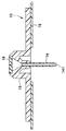
図1Aは、カテーテル14などの注入カニューレと共に使用するための注入セット1を示す。図1Aに示されるように、注入セット1は、基部(10)に脱着可能に取り付けられた流体コネクタまたはハブ22と、流体チュービングセット24と、ポンプ(図示せず)に取り付けるコネクタ26とを備える。ラインセット20は、ハブ22を含み、流体チュービングセット24は、図1Bおよび1Cに示されるように、基部10に取り付けられ、または基部10から取り外される。
FIG. 1A shows an infusion set 1 for use with an infusion cannula, such as a
図1Bは、ハブ22が基部10に取り付けられた注入セット1の上面図である。接着パッド18が、基部10に取り付けられ、ユーザの皮膚に取り付けられるように構成される。図1Cは、ラインセット20が、基部10から取り外されたときの注入セット1の図を示す。基部10は、カテーテル14が取り付けられる注入アダプタ15を含む。
FIG. 1B is a top view of the infusion set 1 with the
図1Dは、注入セット1の断面図であり、どのようにして注入液が、好ましくは軟質プラスチック材料から作製されたカテーテル14内に圧送されるかをより明確に示す。ラインセット20のハブ22は、流体チュービングセット24を受け入れるハブポート29を含む。ハブ22は、流れカニューレ23と、流体チュービングセット24と流れカニューレ23の開放先端部231との間に配置された流体チャネル28とを含む。基部10は、カテーテル14が固定される主要基部部分12を含む。事前に切り込みが入れられた隔壁16は、図1Cおよび1Eに示されるように、ハブ22が注入基部10から取り外されたときにアダプタ15を密閉する。ハブ22が基部10に取り付けられたとき、流れカニューレ24は、事前に切り込みが入れられた隔壁16を貫通し、それにより、流体チャネル28は、カテーテル14と流体連通する。これは、ポンプ(図示せず)からの注入液が、流体チュービングセット24から流体チャネル28内に流れ、そしてカテーテル14に入ることを可能にし、注入液は、カテーテル14の遠位開口部141を出て患者の体内に入る。
FIG. 1D is a cross-sectional view of the infusion set 1 and more clearly shows how the infusate is pumped into a
注入セットおよび/またはパッチポンプにおいて使用するための注入カニューレは、ステンレス鋼などの剛性材料またはTeflon(登録商標)を含む、フッ素化ポリマーなどの軟質プラスチック材料で製造される。注入カニューレは、よじれおよび閉塞を被り得る。 Infusion cannulas for use in infusion sets and / or patch pumps are made of a rigid material such as stainless steel or a soft plastic material such as a fluorinated polymer, including Teflon®. The infusion cannula can suffer from kinking and blockage.
カテーテルは、患者内への挿入中または挿入後、カテーテルチューブがさまざまな原因によって曲がるときによじれる可能性があり、その結果、カテーテルを出る注入液の流れが制限される。よじれは、カテーテルの曲がり、挿入中の導入針上のカテーテルの後退または折り畳みなどの機械的原因による、カテーテルを通る流れの停止であると考えられ得る。 The catheter can be kinked during or after insertion into the patient as the catheter tube bends due to various causes, thereby limiting the flow of infusate exiting the catheter. Kinking can be thought of as stopping flow through the catheter due to mechanical causes such as bending of the catheter, retraction or folding of the catheter over the introducer needle during insertion.
カテーテルの制限された流れは、よじれまたは他の原因によって引き起こされ得る。通常、閉塞は、生物学的、薬理学的、またはよじれを含む機械的原因による流れの阻害または停止であり、これらの不具合は、通常、使用サイクル中に起こる。 The limited flow of the catheter can be caused by kinking or other causes. Usually, occlusion is the inhibition or cessation of flow due to biological, pharmacological, or mechanical causes including kinking, and these failures usually occur during the use cycle.
ステンレス鋼カニューレなどの剛性カテーテルは、鋭敏な先端部を有することができ、この先端部は、従来の挿入器内の導入針と同様に、皮膚を穿孔するために使用される。剛性カテーテルは、よじれが高率で起こる個人に推奨される。しかし、そのような製品は、組織刺激により、部位開通性を低減し得るため、2日を超えての使用は推奨されない。 A rigid catheter, such as a stainless steel cannula, can have a sharp tip that is used to puncture the skin, similar to an introducer needle in a conventional inserter. Rigid catheters are recommended for individuals with a high rate of kinking. However, such products are not recommended for use for more than 2 days as tissue irritations can reduce site patency.
他方では、図1Dに示されるカテーテル14などの軟質のプラスチックカテーテルは、通常の摩耗でよじれまたは閉塞を起こしやすい可能性があるが、一方で剛性カテーテル(図示せず)は、組織内で動き回る傾向があるため、ユーザにとって不快であると見出されることが多い。
On the other hand, soft plastic catheters such as the
注入装置では、ユーザに対してある程度の快適性を維持しながら、カテーテルの閉塞、よじれ、および他の障害のリスクを最小限に抑えることが極めて望ましい。よじれおよび閉塞は、以下で詳細に説明される。 In an infusion device, it is highly desirable to minimize the risk of catheter obstruction, kinking, and other disturbances while maintaining some comfort for the user. Kink and occlusion are described in detail below.
上記で留意されたように、よじれは、機械的原因による、カテーテルを通る流れの停止であると考えられる。この不具合の形態は、挿入中、カテーテルの内径と導入針の外径との間の干渉が十分でないことの結果になり得る。加えて、カテーテルの鈍角の遠位端部が、カテーテルが最初に皮膚の外面を貫通するときに過剰な力をカテーテルに伝えることを可能にする場合、よじれが起こる可能性がある。同様に、挿入の機械化における過剰な跳ね返りまたは振動の結果、過剰な力がカテーテルに伝えられることがある。 As noted above, kinking is believed to be a cessation of flow through the catheter due to a mechanical cause. This form of failure can result in insufficient interference between the inner diameter of the catheter and the outer diameter of the introducer needle during insertion. In addition, kinking can occur if the obtuse distal end of the catheter allows excessive force to be transmitted to the catheter when the catheter first penetrates the outer surface of the skin. Similarly, excessive rebound or vibration in insertion mechanization can result in excessive force being transmitted to the catheter.
よじれはまた、注入または使用のサイクル中にも起こり得る。この不具合の一般的な原因は、カテーテルの構造を弱化させ、それによってカテーテルを曲げ得るまたはねじり得る機械力にカテーテルが抵抗しにくくなる、身体活動中に大きな動きを受ける組織内のカテーテルの配置である。カテーテルの変形を引き起こす損傷もまた、よじれの一因となり得る。 Twisting can also occur during an infusion or use cycle. A common cause of this failure is the placement of the catheter in tissue that undergoes large movements during physical activity, which weakens the structure of the catheter, thereby making it less resistant to mechanical forces that can bend or twist the catheter. is there. Damage that causes catheter deformation can also contribute to kinking.
可撓性カテーテルには、患者への挿入しやすさ、患者の快適性、および適正なコストなどの多くの利点が存在する。しかし、いくつかの欠点もまた存在し得る。可撓性カテーテルは、通常、非可撓性カテーテルよりよじれを起こしやすい。ほとんどの可撓性カテーテルで使用される材料は、Teflon(登録商標)などのポリマーである。そのような材料は、カテーテルに可撓性をもたらす。しかし、そのようなカテーテルの可撓性質はよじれの一因となり、その理由は、そのようなカテーテルの壁は剛性ではなく、したがって、カテーテルおよび/または患者の動きによって変形を起こしやすいためである。 There are many advantages to flexible catheters, such as ease of insertion into a patient, patient comfort, and reasonable cost. However, some drawbacks can also exist. Flexible catheters are usually more susceptible to kinking than non-flexible catheters. The material used in most flexible catheters is a polymer such as Teflon®. Such a material provides flexibility to the catheter. However, the flexible nature of such catheters contributes to kinking because the walls of such catheters are not rigid and are therefore prone to deformation due to catheter and / or patient movement.
したがって、上記で留意された欠点を最小限にしながらカテーテルの機能性を改良する、改良されたカテーテル設計および構造に対する必要性が存在する。より詳細には、よじれの一因となる可撓性設計の負の面を有さずにその可撓特性を維持する可撓性カテーテルの設計および構造を改良する必要性が存在する。 Accordingly, there is a need for improved catheter designs and structures that improve catheter functionality while minimizing the disadvantages noted above. More particularly, there is a need to improve the design and construction of flexible catheters that maintain their flexible properties without having the negative aspects of the flexible design that contribute to kinking.
本発明の目的は、可撓性カテーテルであって、その可撓特性および引張強度を維持しまたは改良しながら、また、患者への挿入および患者からの取り外しの能力に有害な影響を与えずに、柱強度を最適化するように構成され配置された可撓性カテーテルを提供することである。 An object of the present invention is a flexible catheter that maintains or improves its flexible properties and tensile strength, and without adversely affecting the ability to be inserted into and removed from a patient. It is to provide a flexible catheter constructed and arranged to optimize column strength.
これらおよび他の目的は、膨張不能な外側スリーブによって取り囲まれた膨張可能な内側チューブを有する可撓性カテーテルであって、前記膨張可能な内側チューブが、前記カテーテルを通して投与された注入液または他の流体の一部を吸収した際に膨張して前記カテーテルの壁強度を増大させる、可撓性カテーテルを提供することによって実質的に達成される。これは、前記内側チューブの外方向の拡張が、前記膨張不能な外側スリーブによって抑制されながら、よじれまたは他のタイプの阻害に対するカテーテルの抵抗性を改良する。前記改良されたカテーテルは、インスリンまたは他の薬剤をカテーテルを介して投与することを可能にしながら、よじれおよび他の望ましくない障害を回避するよう強度を最適化するように構成され得る。前記改良されたカテーテルは、注入セット、挿入機構、またはパッチポンプの変更を有さずに従来のカテーテルに置き代わることができる。 These and other objects are flexible catheters having an inflatable inner tube surrounded by an inflatable outer sleeve, the inflatable inner tube being infused through the catheter or other This is substantially achieved by providing a flexible catheter that expands upon absorption of a portion of fluid to increase the wall strength of the catheter. This improves the catheter's resistance to kinking or other types of inhibition while the outward expansion of the inner tube is constrained by the non-inflatable outer sleeve. The improved catheter may be configured to optimize strength to avoid kinking and other undesirable obstacles while allowing insulin or other drugs to be administered through the catheter. The improved catheter can replace conventional catheters without modification of the infusion set, insertion mechanism, or patch pump.
本発明のさまざまな目的、利点、および新規の特徴は、その例示的な実施形態の以下の詳細な説明から、付属の図を併用して読み取ることによってより容易に理解されるであろう。 Various objects, advantages, and novel features of the present invention will be more readily understood from the following detailed description of exemplary embodiments thereof, read in conjunction with the accompanying figures.
図および以下の説明において記載される例示的な実施形態に参照がなされるが、本明細書において開示される実施形態は、本発明によって包含されるさまざまな代替の設計および実施形態の包括的なものであることを意味するものではない。 Reference is made to the exemplary embodiments described in the figures and the following description, however, the embodiments disclosed herein are generic to the various alternative designs and embodiments encompassed by the present invention. It does not mean that it is a thing.
図2〜7に示されるように、本発明の例示的な実施形態は、図1Aおよび1Dのカテーテル14と同じやり方で機能することができるカテーテル14aである。カテーテル14aは、(1)好ましくは膨張可能なポリマーから生成された膨張可能な内側チューブ100と、(2)好ましくは膨張不能なポリマーから生成された外部の膨張不能な外側スリーブ200とから構成される。膨張可能な内側チューブ100は、図10Aおよび10Bに示されるように、チューブ以外の構造に置き換えられ得る。膨張不能な外側スリーブ200は、図1Aおよび1Dのカテーテル14のようにサイズ設定され成形される。
As shown in FIGS. 2-7, an exemplary embodiment of the present invention is a
通常、この文脈での「膨張可能」は、液体などの何かを吸収し、吸収によって体積またはサイズ的に膨張する材料の能力を説明する。液体の吸収または非吸収が対象とされ得る。たとえば、1つの物は、その組成および/または構成により、特定の液体を吸収することができないが、別の物は、同じ液体を吸収し、サイズまたは体積的に膨張することができる可能性がある。そのような特性は、本発明において効果的に利用される。 Usually, “expandable” in this context describes the ability of a material to absorb something, such as a liquid, and expand in volume or size upon absorption. Absorption or non-absorption of liquids can be targeted. For example, one object may not be able to absorb a particular liquid due to its composition and / or configuration, while another object may be able to absorb the same liquid and expand in size or volume. is there. Such characteristics are effectively utilized in the present invention.
図2〜7の膨張可能な内側チューブ100は、好ましくは、ポリウレタンなどの膨張可能なポリマーから生み出される。より具体的には、Becton、Dickinson and Company(BD)によるVialon(商標)生体材料などのポリウレタン生成物が、図2〜7の膨張可能な内側チューブ100または図9Aおよび9Bの膨張可能なセグメント100bを作成するために使用され得る。膨張可能な内側チューブ100は、これが接触する、カテーテルを介して投与された液体注入液の一部分を吸収して、その体積を膨張させる。インスリンを含有する注入液では、Vialon(商標)生体材料は、インスリンそのものではなく、インスリンが中に懸濁された液体溶液を吸収する。Vialon(商標)生体材料によって吸収された液体は、ほとんど水である。膨張可能な内側チューブ100の膨張の量および速度は、その組成を配合し、さまざまな構造をもたらして所望の特性を生み出すことによって調節され得る。患者に投与されるインスリンは、通常、水含量が通常は95%を上回る水溶液中にあり、水は、Vialon(商標)生体材料によってより容易に吸収されることが留意される。
The inflatable
たとえば、Vialon(商標)生体材料は、これが、サイズまたは体積的に30%から300%膨張することができるように、液体の吸収による膨張の程度を調節するように配合され得る。したがって、材料配合の慎重な選択によって、膨張可能な内側チューブ100の膨張の量、体積、および速度が、調節され得る。例示的な目的のために、本発明の実施形態では、膨張可能な内側チューブ100の最大膨張は、約60%に設定されるが、特有の使用に合わせて変更され得る。例示的なVialon(商標)生体材料のさらなる開示は、本発明の譲受人に譲渡されたMin−Shiu Leeらの特許文献1および特許文献2、Theo Onwunakaらの特許文献3、ならびにGary Searleらの特許文献4において見出されることが可能であり、前述の文献の各々の全体的内容、開示、および主題は、参照によって本明細書に明示的に組み込まれる。Vialon(商標)生体材料ポリマーは、生理的状態との適合性をもたらし、Vialon(商標)生体材料ポリマーは、抽出可能でありそれによって生物医学用途では望ましくないことがある抗酸化剤および脱粘着剤などの処理添加物を通常は必要としないという付加された利点を有する。Vialon(商標)生体材料は、熱可塑性ポリウレタンであり、したがって、押し出しおよび射出成形などの技術を用いて熱形成され得る。
For example, the Vialon ™ biomaterial can be formulated to adjust the degree of expansion due to liquid absorption so that it can expand 30% to 300% in size or volume. Thus, by careful selection of material formulation, the amount, volume, and rate of expansion of the expandable
膨張可能な内側チューブ100および膨張不能な外側スリーブ200は、組み合わさってカテーテル14aを形成し、このカテーテル14aは、インスリンの送達または注入において従来のカテーテルと同様に機能することができる。したがって、カテーテル14aは、図1A〜1Dに示されるような注入送達セット、またはパッチポンプにおける図1Dのカテーテル14に対して代用され得る。
The inflatable
カテーテル14aが、インスリン注入セットまたはパッチポンプにおける従来のカテーテルに対して代用されるとき、カテーテル14aを患者に取り付け、挿入するために、図6に示されるような導入針50が、カテーテル14aの膨張可能な内側チューブ100に挿入される。組み合わされたカテーテル14aおよび導入針50は、次いで、患者の皮膚に挿入され、導入針50は、カテーテル14aが患者に取り付けられたまま引き出される。これは、インスリン注入セットのカテーテルを挿入する従来の方法に類似する。このプロセス中、膨張可能な内側チューブ100の内面は、導入針50と接触することができるが、膨張可能な内側チューブ100は、膨張可能な内側チューブ50またはカテーテル14a全体に損傷を引き起こす、導入針50との過剰な干渉が存在しないように寸法設定される。
When the
図6に示される導入針は、0.0163インチ(0.0414cm)の直径を有する27gカニューレでよい。膨張可能な内側チューブ100は、27gカニューレを収容するようにサイズ設定され構成される。膨張不能な外側スリーブ200の内径は、0.0248インチ(0.063cm)になることができ、より薄いセグメント140の厚さは、0.002インチ(0.005cm)になることができ、より厚いセグメント120の厚さは、0.004インチ(0.01cm)になることができ、これが導入針50を収容することになる。
The introducer needle shown in FIG. 6 may be a 27 g cannula having a diameter of 0.0163 inches (0.0414 cm). The inflatable
その後、カテーテル14aを介した患者へのインスリンの注入または送達は、所望に応じて、所要に応じて、および/またはプログラムされたように(たとえば図1A〜1Dに示されるように)インスリン注入セットを介して起こる。複数の注入が行われてから、カテーテル14aが、よじれまたは閉塞によって引き起こされた何らかの阻害によって閉塞される可能性があり、その後は、カテーテル14aは、患者から取り外され、破棄される。
Thereafter, infusion or delivery of insulin to the patient via
図2〜6は、説明を容易にするためにカテーテル14aを管状構造として表すが、遠位開口部141の反対側の端部が、(図1Cおよび1Dのアダプタ15のような)アダプタに取り付けるように成形され得ることが留意される。換言すれば、カテーテル14aは、従来のカテーテルの外部形状を有することができる。しかし、図1Cおよび1Dのカテーテル14とは異なり、カテーテル14aは、膨張可能な内側チューブ100を含む。
2-6 depict the
インスリン注入が起こるとき、インスリンは、膨張可能な内側チューブ100を介して患者に送達され、この膨張可能な内側チューブ100は、その構成材料(たとえばVialon(商標)生体材料)により、患者に投与された注入液(ほとんど水)の一部を吸収することができる。特にインスリンは通常吸収されないため、吸収される量は無視できるものであり、所望のインスリン療法に影響は与えない。図2および4は、膨張可能な内側チューブ100による任意の注入液の吸収前のカテーテル14aを示す。注入液の一部を吸収した際、膨張可能な内側チューブ100は、図3および5に示されるように内方向および外方向の両方に膨張する。図3および5に示されるように、膨張可能な内側チューブ100の外方向の膨張は、膨張不能な外側スリーブ200によって抑えられる。外方向の膨張は、膨張不能な外側スリーブ200によって抑えられるため、膨張可能な内側チューブ100の膨張または拡張は、図3、5、および8〜10に示されるように内方向に向けられる。
When insulin infusion occurs, insulin is delivered to the patient via the inflatable
また、膨張可能な内側チューブ100の膨張の方向を調節することが好ましいが、その理由は、調節されない拡張は、患者に不快感を引き起こし、カテーテル14a内に、断裂を引き起こし得る隆起または弱化点を作り出すなどの他の望ましくない結果を有し得るためである。膨張可能な内側チューブ100の外方向の拡張を調節するために、外部の膨張不能な外側スリーブ200は、図2〜7に示されるように、膨張可能なチューブ100の周りに配置される。外部の膨張不能な外側スリーブ200は、Teflon(登録商標)または類似のポリマーなどの、液体の吸収によって著しくは膨張しない材料から作製され得る。膨張不能な外側スリーブ200は、膨張可能な内側チューブ100に摩擦嵌合、融合、または別の形で連結されてカテーテル14aを形成することができる。また、膨張可能な内側チューブ100および膨張不能な外側スリーブ200が、たとえば同時押し出しプロセスを介して、2つの部分を組み立てることなく単一ユニットとして作製されることも可能である。
It is also preferable to adjust the direction of inflation of the inflatable
好ましくはTeflon(登録商標)から作製された膨張不能な外側スリーブ200は、これと接触する液体を著しくは吸収せず、サイズ的に著しくは膨張しない。膨張不能な外側スリーブ200は、膨張可能な内側チューブ100が、注入液の液体の吸収時に膨張するとき、膨張可能な内側チューブ100の外方向の膨張または拡張を抑えるように作用する。膨張不能な外側スリーブ200は、膨張可能な内側チューブ100の外方向の膨張または拡張を保持するのに十分な強度を有するように構成される。たとえば、膨張不能な外側スリーブ200の強度は、その厚さを増大させることによって増大され得る。
The non-expandable
用語「膨張可能」および「膨張不能」は、相対的であり、絶対的な意味では使用されないことを理解されたい。たとえば、膨張不能な外側スリーブ200は、その膨張の量が、外側スリーブ200が上記で論じられたような膨張可能な内側チューブ100の外方向の膨張を抑えるのを可能にするのに十分小さければ、注入液または体液にさらされたときに、またはさらには熱によって受ける膨張はわずかなものであり得る。換言すれば、外側スリーブ200は、これが内側チューブ100より小さい膨張であれば、幾分膨張可能になることができる。そして、その反対に、内側チューブ100は、これが外側スリーブ200より膨張可能であれば、著しく膨張可能である必要はない。
It should be understood that the terms “expandable” and “non-expandable” are relative and are not used in an absolute sense. For example, the non-expandable
図7に示されるように、膨張不能な外側スリーブ200は、好ましくは、膨張不能な外側スリーブ200の内径D1と外径D2の間の相違である、約0.0005インチ(0.0013cm)の壁厚を有するTeflon(登録商標)収縮チュービングなどの薄壁構造である。外側スリーブの外径D2および内径D1は、それぞれ0.026インチ(0.066cm)および0.025インチ(0.064cm)であってもよい。膨張不能な外側スリーブ200は、図7の矢印で示されるように、膨張可能な内側チューブ100の外方向の拡張および関連する拡張力を抑えるように構成される。そのような目的のために、さまざまな厚さのTeflon(登録商標)収縮チュービングが、外側スリーブ200に使用され得る。0.00025インチ(0.00064cm)ほどの小ささの厚さを有するTeflon(登録商標)収縮チュービングが市販されており、そのような収縮チュービングは、外部の膨張不能な外側スリーブ200を形成するために使用され得る。
As shown in FIG. 7, the non-expandable
インスリン治療が開始されたとき、インスリンを含有する注入液は、カテーテル14a内に圧送され、膨張可能な内側チューブ100は、注入液の液体が吸収されるにつれて膨張し始める。膨張不能な外側スリーブ200は、カテーテル14aの中心線の視点からの、膨張可能な内側チューブ100の外方向の膨張または外方向の拡張を防止し、膨張可能な内側チューブ100aの膨張または拡張は、カテーテル14aの中心線に向かって内方向に、そして膨張不能な外側スリーブ200の内径D1に沿って円周方向に、図7の矢印の方向に向けられる。
When insulin treatment is initiated, the infusate containing insulin is pumped into the
内側チューブ100の膨張の方向は、図2および7に示されるように、膨張可能な内側チューブ100を交互のより厚いセグメント120およびより薄いセグメント140ならびにより薄いセグメント140上のへこみ142を含むように構成することによって調節され得る。膨張可能な内側チューブ100がサイズ的に膨張するにつれて、より薄いセグメント140は、そのそれぞれのへこみ142においてカテーテル14aの中心線に向かって内方向に折り畳まれて、図3および5に示されるように内部脚部146を形成する。より薄いセグメント140およびより厚いセグメント120がサイズ的に膨張するときの内部脚部146の形成が、カテーテル14aの構造強度を増大させる。へこみ142は、図2に示されるようにより薄いセグメント140の長さに沿って通ることができ、1または複数のへこみは、膨張可能な内側チューブ100の内面および/または外面上に形成されて、内側チューブ100の膨張の方法および方向を調節することができる。より厚いセグメント120の膨張または成長は、より薄いセグメント140の移動および折り畳みに影響を与えて内部脚部146を形成する。
The direction of inflation of the
加えて、膨張可能な内側チューブ100の、カテーテル14aの中心線に向かい、膨張不能な外側スリーブ200の内径D1に沿った円周方向の膨張は、膨張可能な内側チューブ100の内面に沿って形成されたカテーテルオリフィス160が、注入液がカテーテル14aに圧送されることを可能にするために開いたままになるように調節される。内側チューブ100が、図3および5に示されるように、これが接触する液体注入液および/または体液の吸収によってその最大サイズに膨張したとき、カテーテルオリフィス160の断面が低減されている場合であっても、オリフィス160は開いたままであり、それにより、インスリン注入は、阻害または背圧アラームを始動させることなく、膨張可能な内側チューブ100を介して起こることができる。
In addition, a circumferential expansion of the inflatable
図1〜7に示されるカテーテル実施形態では、図7により明確に示されるように、膨張可能な内側チューブ100の断面は、六角形に似た6つのセグメントを有する。3つのより薄いセグメント140間には、3つのより厚いセグメント120が交互に位置する。より薄いセグメント140は、膨張中のセグメント120、140の移動を調節するために、またより薄いセグメント140が、内部脚部146を形成するようにへこみ142において内方向に折り畳まれるように特有の場所、へこみ142においてさらに薄くまたは弱化されている。セグメント120、140およびへこみ142は、好ましくは、膨張可能な内側チューブ100の長さに沿ってほぼ連続的にかつ一様に通る。膨張可能な内側チューブ100の六角形の配置が示されているが、カテーテル14a全体の構造的完全性を強化し、また、内側チューブ100がサイズ的に膨張するときにインスリン療法を可能にするのに十分なカテーテル開口部またはオリフィス160を維持するという目的を維持しながら、より多いまたはより少ない辺が存在することができる。
In the catheter embodiment shown in FIGS. 1-7, as more clearly shown in FIG. 7, the cross section of the inflatable
図8Aおよび8Bは、本発明の別の例示的なカテーテル実施形態の断面図を示す。図8Aおよび8Bのカテーテル14bは、図2〜7のカテーテル14aに類似する。図7の膨張可能な内側チューブ100とは異なり、カテーテル14bの膨張可能な内側チューブ100aはより厚いセグメント120aを含み、その各々は、導入針50の外面を収容するようにカスタマイズされた凹状表面122を有する。そのような配置は、図8Aに示されるように、より膨張可能な材料を内側チューブ100a内に収容することができる。導入針50の円筒状の外面の部分は、図8Aに示されるように、より厚いセグメント120aの相互に成形された凹状表面122において受け入れられる。膨張可能な内側チューブ100aのより薄いセグメント140もまた、図8Aに示されるように、導入針50と接触することもできる。より薄いセグメント140は、これらが、導入針50によってわずかに外方向に押し出され得るように十分薄く可撓性になるように作製され得る。加えて、より薄いセグメント140上のへこみ142は、導入針50に対するより薄いセグメント140の抵抗性を低減するように構成され得る。
8A and 8B show cross-sectional views of another exemplary catheter embodiment of the present invention. The
図8Bは、導入針50を有さないカテーテル14bを示す。カテーテル14bの例示的な寸法は、以下の通りに規定される。図8Aに示されるように、膨張不能な外側チューブ200の外径D1は、0.026インチ(0.066cm)であり、外側チューブ200の壁厚T1は、0.0005インチ(0.0013cm)である。図8Bに示されるように、より薄いセグメント140の各々の壁厚T2は、0.002インチ(0.005cm)であり、これは、へこみ142が存在するところではさらに低減される。より厚いセグメント120の壁圧は、これらが、図8Bに示されるように外側スリーブ200の内径に従うにつれて変化するが、より厚いセグメント120の厚さT3は、0.004インチ(0.01cm)である。より厚いセグメント140の各々にさらに関して、その外壁の半径R1は、0.012インチ(0.03cm)であり、内壁の半径R2は、凹状表面122において0.008インチ(0.02cm)であり、これは、0.004インチ(0.01cm)の厚さをもたらす。加えて、より薄いセグメント140の各々の回転角度A1は、45度に設定可能であり、より厚いセグメント120の各々の回転角度A2は、75度になることができ、これは、図8Bには膨張可能な材料における60%の拡張に対応するように示される。
FIG. 8B shows the
図8C、8D、および8Eは、膨張不能な外側チューブ200を示さない、図8Aおよび8Bの実施形態の断面を示す。しかし、内側チューブ100aの実際の膨張は、膨張不能な外側スリーブ200内で起こることに留意されたい。図8Cは、より薄いセグメント140が内部脚部146を形成するように折り畳まれた後の、内側チューブ100aの初期膨張を示す。図8Dは、これがサイズ的に完全に膨張し、これ以上膨張できなくなった後の内側チューブ100aを示す。図8Dでは、内部脚部146およびより厚いセグメント120は、オリフィス160を低減するようにサイズ的に増大している。
8C, 8D, and 8E show a cross-section of the embodiment of FIGS. 8A and 8B that does not show the non-inflatable
図8Dは、サイズ的に約60%膨張した後の膨張可能な内側チューブ100aを示す。図8Dは、カテーテル14bの膨張可能な内側チューブ100aを介してインスリンを投与するのに十分なカテーテルオリフィス160の開口部を維持しながら、インスリンの最大吸収が起こった後の内側チューブ100aを示す。膨張可能な内側チューブ100aおよび外部の膨張不能な外側スリーブ200とのその接面の調節された膨張は、カテーテル14a、14bの構造的完全性と、カテーテルの圧潰、よじれ、または圧迫の一因となる外部力に抵抗することとを改良する。
FIG. 8D shows the inflatable
本発明を開発する上で、カテーテルの内径の閉塞または阻害の程度を増大させる結果から生じる注入ポンプにおける背圧の増大を決定するために、分析が行われた。膨張可能な内側チューブ100aが、液体吸収により、サイズ的に膨張するとき、オリフィス160は、これが内側チューブ100aの膨張によって変位されるにつれてサイズ的に低減される。分析は、カテーテルオリフィス160の断面積の60%の低減であっても、注入ポンプにおいて背圧4psi(ポンド毎平方インチ)(27,580Pa)の最小限の増大しか生じなかったことを示した。
In developing the present invention, an analysis was performed to determine the increase in back pressure in the infusion pump resulting from increasing the degree of occlusion or inhibition of the inner diameter of the catheter. When the inflatable
図8Eに示される例では、膨張可能な内側カテーテルは、60%膨張可能なVialon(商標)生体材料から作製され、0.00016076平方インチ(1.03715922×10⁻⁷m2)の断面積C1を有するカテーテルオリフィス160(内側チューブ100aの内側の面積)を有して示される。図8Dに示されるように、最大の膨張を受け、支持内部脚部146を完全に形成した後、カテーテルオリフィス160の断面積の低減は、42%のみであり、圧縮されなかった管腔空間は、図8Eに示される0.0000241平方インチ(1.5548356×10⁻⁸m2)断面積C2(最も内側の円の内側の面積)、つまり、ポンプが閉塞アラームを始動させる、または注入療法の損失を引き起こすまでのポンプ圧力の増大を結果としてもたらす断面積よりかなり大きい。
In the example shown in FIG. 8E, the inflatable inner catheter is made from 60% inflatable Vialon ™ biomaterial and has a cross-sectional area C1 of 0.000166072 inches (1.03715922 × 10 −7 m 2). Catheter orifice 160 (area inside
図9Aおよび9Bは、本発明のカテーテルの別の実施形態を示す。図9Aに示されるように、カテーテル14cは、膨張可能な内側チューブ100bを含む。膨張可能な内側チューブ100bは、膨張不能な外側スリーブ200の内径周りに等しく離間された3つの主要な膨張可能なセグメント125と、隣接する主要な膨張可能なセグメント145を連結する薄い連結セグメント145とを備えた複合構造になることができる。カテーテルオリフィス160は、主要な膨張可能なセグメント125間に形成された横方向オリフィス161を含む。主要な膨張可能なセグメント125は、導入針をその間に収容する前表面126を含む。
Figures 9A and 9B show another embodiment of the catheter of the present invention. As shown in FIG. 9A, the
膨張可能な内側チューブ100bが注入液から液体を吸収し、図9Bに示されるようにサイズ的に膨張した後、内側チューブ100bは、サイズ的に膨張し、横方向オリフィス161を含むカテーテルオリフィス160は、サイズ的に低減されるが開いたままである。主要な膨張可能なセグメント125の各々の前表面126もまた、これらが、対向する横方向オリフィス161に嵌合できないようにサイズ的に増大する。他の実施形態において説明されたように、主要な膨張可能なセグメント125および薄い連結セグメント145は、特有の場所において薄くまたは弱化されて、膨張可能な内側チューブ100bが、注入液からの液体が吸収されるにつれて膨張するときに、拡張または膨張の動作を調節し、および/または折り畳みを引き起こすことができる。
After the expandable
図10Aおよび10Bは、本発明のカテーテルの別の実施形態を示す。カテーテル14dでは、他の実施形態でのように内側の膨張可能なチューブは存在しない。その代わり、図10Aに示されるように、最初に相互連結されない、Vialon(商標)生体材料などの膨張可能な材料から作製された膨張可能なセグメント105が存在する。膨張可能なセグメント105はそれぞれ、より厚いセグメント125と、薄いセグメント脚部145の対とを含む。膨張可能なセグメント105は、さまざまな手段によって膨張不能な外側スリーブ200aの内壁に取り付けられ得る。図10Aおよび10Bに示されるように、膨張不能な外側スリーブ200aは、膨張可能なセグメント105がその上に取り付けられる保持タブ210を含む。膨張可能なセグメント105および保持タブ210を有する外側スリーブ200aは、カテーテル14dを形成するように同時押し出しされ、所要の長さに切断され得る。
10A and 10B illustrate another embodiment of the catheter of the present invention. In
膨張可能なセグメント105がサイズ的に膨張するとき、薄いセグメント脚部145の隣り合うものは、図10Bに示されるように膨張し、オリフィス160に向かって内方向に折り畳まれる。より厚いセグメント125の膨張もまた、薄いセグメント脚部145の折り畳み運動を促し、図3および8Dに示される実施形態に類似する断面を形成する。膨張可能なセグメント105が、サイズ的に完全に膨張した後でも、カテーテルオリフィスまたは管腔160は、カテーテル14dの構造的完全性を増大させながら、妨害の無い注入療法を可能にするために開いたままである。加えて、他の実施形態において説明されたように、膨張可能なセグメント105は、特有の地点において薄くまたは弱化されて、拡張または膨張の動作を調節し、および/または折り畳みを引き起こすことができ、それにより、複合構造は、膨張が完了した後、カスタマイズされた断面を形成することができる。
As the
図11Aは、図8Aのカテーテル14bが、シミュレーション式の圧縮試験にかけられて、従来のカテーテルと比較したときの、本発明のカテーテル14bを圧縮するのに必要とされる力を比較した有限要素分析(FEA)を示す。FEAシミュレーションでは、カテーテル14bは基部92上に置かれ、プローブ90が、膨張可能な内側チューブ100の膨張のさまざまな段階においてカテーテル14b上に押し込まれて、カテーテル14bによる圧縮に対する抵抗を観察した。図11Bは、カテーテルオリフィス160の断面積が、プローブ90による圧縮前に、その元のサイズの約42%に低減されるようにサイズ的に膨張した内側の膨張可能な内側チューブ100aを備えた、カテーテル14bを示す。図11Cは、設定された圧縮力がかけられた後のカテーテル14bを示す。膨張による膨張可能な内側チューブ100の厚くされた壁、より厚いおよびより薄いセグメント120a、140などのその構成要素の構成、ならびに内部脚部146の形成が、全圧潰に抵抗し、インスリン療法を投与するのに十分なカテーテルオリフィス160の開口部を維持した。
FIG. 11A shows a finite element analysis comparing the force required to compress the
比較において、図11Dは、FEAシミュレーションにおいて同じように設定された圧縮力をかける前の従来のカテーテル220を示す。図11Eは、その設定された圧縮力がかけられた後の従来のカテーテル220を示す。カテーテル14bのような内部の支持構造を有さない従来のカテーテル220は圧縮に抵抗できず、その結果、カテーテルオリフィス160はほぼ完全に圧潰し、これは、そのような圧潰が注入療法中に起こった場合には閉塞アラームを始動させていたと考えられる。圧縮力は、カテーテルが被り得る、よじれおよび/または閉塞を引き起こす状態をシミュレートする。
In comparison, FIG. 11D shows a
有限要素分析は、本発明のカテーテル14bが、閉塞アラームを始動させる前、従来のカテーテル220の約2倍の力の量に耐えることが予想され得ることを示した。従来のカテーテル22に対する、閉塞アラームが始動され得る前の最小限の面積まで圧迫するのに必要とされる力は、0.334lb(0.1515kg)であり、一方で本発明のカテーテル14bに対する、最小限の面積まで圧迫するのに必要とされる力は、0.660lb(0.2994kg)であった。
Finite element analysis has shown that the
本発明のカテーテル14a、14bの製造および組み立てが、次にさらに説明される。1部分の膨張可能な内側チューブ100、100aは、当技術分野でよく知られている連続的な押し出しプロセスから生成され得る。外部の膨張不能な外側スリーブ200もまた、連続的な押し出しプロセスから生成され得る。外部の膨張不能な外側スリーブ200は、2部分を一緒に組み立ててカテーテル14a、14bの滑合組み立てを可能にするために、膨張可能な内側チューブ100、100aの外径よりわずかに大きい内径を有して製造され得る医療級のTeflon(登録商標)収縮チュービングから生成され得る。膨張不能な外側スリーブ200全体は、直径において収縮され、または膨張不能な外側スリーブ200の前端部だけが直径において収縮されて、2つの構成要素を繋げてカテーテル14a、14bを形成することができる。その後、2部分組立体は、外部の膨張不能な外側スリーブ200の前端部を膨張可能な内側チューブ100、100aにさらに結合させる無線周波(RF)チッピング(tipping)によって完了され得る。あるいは、膨張可能な内側チューブ100、100aが、最終の長さおよび先端部寸法に成形され、外部の膨張不能な外側スリーブ200が、上記で説明されたように取り付けられることも可能である。類似のプロセスは、図10Aおよび10Bのカテーテル14dを形成することができる。
The manufacture and assembly of the
図9Aおよび9Bの複合カテーテル14cに関して、膨張可能な内側チューブ100bおよび外部の膨張不能な外側スリーブ200は、従来のプロセスを用いて連続的に押し出されおよび/または同時押し出しされ得る。Teflon(登録商標)収縮チュービングは、外部の膨張不能な外側スリーブ200を作製するために使用され得る。膨張可能な内側チューブ100bおよび膨張不能な外側スリーブ200の膨張可能なセグメント125、145は、同時押し出しされ所望の長さに切断され得る。
With respect to the
膨張可能な内側チューブ100、100a、100bおよび膨張可能なセグメント105は、同時押し出しまたは2個取り成形されることが可能であり、外部の膨張不能な外側スリーブ200は、上記で説明された方法によって膨張可能なチューブ100、100a、100bまたは膨張可能なセグメント105に取り付けられ得る。図9Aおよび9Bの複合カテーテル14cは、膨張可能なポリマーのセグメントで外側被覆されまたはこれと共に同時押し出しされる膨張不能なスリーブから構成され得る。
The inflatable
例としてカテーテル14bを引用する本発明のカテーテルには、従来技術に勝る数多くの利点および改良が存在する。膨張可能な内側チューブ100aが膨張した後、カテーテル14bの全体構造は、よじれに抵抗する、またはこれを最小限に抑えることができるが、その理由は、材料膨張の結果として形成された内部脚部146が、全体構造の完全な圧潰に抵抗するためである。それと同時に、インスリンの流れは、カテーテルオリフィス160を通して可能である。カテーテルオリフィス160の断面が、材料膨張によって低減される場合であっても、十分な開口部が維持され、それにより、必要とされるポンプ圧力は、ポンプの通常の流れ状態を超えず、閉塞アラームを始動させない。
There are numerous advantages and improvements over the prior art in the catheter of the present invention that cite
別の利点は、本発明のよじれ耐性カテーテル14は、潜在的に、留置可撓性ステンレス鋼針、または部分的後退導入針などの他のよじれ防止カテーテル構造より生成するのに高価でないことである。そのような代替のステンレス鋼針は、より剛性であり、患者に対するより大きい不快感を引き起こし得る。
Another advantage is that the kink
本発明の装置の別の利点は、膨張可能な内側チューブ100aおよび膨張不能な外側スリーブ200を含む耐圧潰性カテーテル14bの全体寸法およびゲージサイズが、24ゲージ導入針および27ゲージカテーテルなどの、インスリン注入に現在使用されるゲージサイズに適合することである。換言すれば、カテーテル14bは、大きな変更を有することなく、インスリン注入セットに使用される従来カテーテルに対して代用され得る。カテーテル14bに関して上記で述べられた利点は、全般的に、カテーテル14a、14cおよび14dにも言うことができる。
Another advantage of the device of the present invention is that the overall size and gauge size of the
本発明のわずかな例示的な実施形態のみが上記で詳細に説明されてきたが、当業者は、数多くの改変が、本発明の新規の教示および利点から実質的に逸脱することなく例示的な実施形態において可能であることを容易に理解するであろう。したがって、すべてのそのような改変は、付属の特許請求の範囲およびその等価物において規定された本発明の範囲内に含まれることが意図される。 While only a few exemplary embodiments of the present invention have been described in detail above, those skilled in the art will recognize that numerous modifications are possible without substantial departure from the novel teachings and advantages of the present invention. It will be readily understood that this is possible in the embodiment. Accordingly, all such modifications are intended to be included within the scope of this invention as defined in the appended claims and their equivalents.
Claims (20)
内側要素と、
前記内側要素の外壁を覆う外側スリーブと
を備え、
前記内側要素は、膨張可能な材料を含み、
前記外側スリーブは、膨張不能な材料を含み、
前記内側要素は、前記カテーテルを介して投与された液体を吸収し、体積的に膨張するとともに、
前記内側要素の外方向の膨張は、前記膨張不能な外側スリーブによって抑えられることを特徴とする耐圧潰性カテーテル。 A collapsible catheter,
An inner element,
An outer sleeve covering the outer wall of the inner element,
The inner element comprises an inflatable material;
It said outer sleeve, only contains a non-inflatable material,
The inner element absorbs fluid dispensed through the catheter and expands in volume;
The pressure-resistant collapsible catheter is characterized in that outward expansion of the inner element is suppressed by the non-expandable outer sleeve .
膨張可能な材料を押し出すことによって内側要素を形成するステップと、
膨張不能な材料を押し出すことによって外側スリーブを形成するステップと、
前記内側要素を前記外側スリーブに挿入するステップと、
前記外側スリーブを前記内側要素上で収縮させて前記カテーテルを形成するステップとを含むことを特徴とする方法。 A method of making the catheter of claim 1 , comprising:
Forming an inner element by extruding an inflatable material;
Forming an outer sleeve by extruding a non-expandable material;
Inserting the inner element into the outer sleeve;
Shrinking the outer sleeve over the inner element to form the catheter.
基部と、
前記基部に脱着可能に取り付けられたハブと、
ポンプと、
前記ポンプおよび前記基部を連結する流体チュービングセットと、
請求項1に記載のカテーテルであって、
膨張可能な内側要素と、
前記チュービングの外壁を覆う膨張不能な外側スリーブとを備え、
前記膨張可能な内側要素は、前記膨張不能な外側スリーブの内面に取り付けられる、
カテーテルと
を備えることを特徴とする注入システム。 An injection system,
The base,
A hub removably attached to the base;
A pump,
A fluid tubing set connecting the pump and the base;
The catheter according to claim 1 ,
An inflatable inner element;
A non-inflatable outer sleeve covering the outer wall of the tubing;
The inflatable inner element is attached to an inner surface of the non-inflatable outer sleeve;
An infusion system comprising a catheter.
基部と、
前記基部に脱着可能に取り付けられたハブと、
ポンプと、
前記ポンプおよび前記基部を連結する流体チュービングセットと、
請求項1に記載のカテーテルであって、
膨張可能な内側要素と、
前記チュービングの外壁を覆う膨張不能な外側スリーブとを備え、
前記膨張可能な内側要素は、前記膨張不能な外側スリーブの内面に取り付けられる、
カテーテルと
を備えることを特徴とするパッチポンプ。 A patch pump,
The base,
A hub removably attached to the base;
A pump,
A fluid tubing set connecting the pump and the base;
The catheter according to claim 1 ,
An inflatable inner element;
A non-inflatable outer sleeve covering the outer wall of the tubing;
The inflatable inner element is attached to an inner surface of the non-inflatable outer sleeve;
A patch pump comprising a catheter.
Applications Claiming Priority (3)
| Application Number | Priority Date | Filing Date | Title |
|---|---|---|---|
| US13/479,114 | 2012-05-23 | ||
| US13/479,114 US10220186B2 (en) | 2012-05-23 | 2012-05-23 | Collapse-resistant swellable catheter |
| PCT/US2013/038890 WO2013176850A1 (en) | 2012-05-23 | 2013-04-30 | Collapse-resistant swellable catheter |
Publications (2)
| Publication Number | Publication Date |
|---|---|
| JP2015517384A JP2015517384A (en) | 2015-06-22 |
| JP6375292B2 true JP6375292B2 (en) | 2018-08-15 |
Family
ID=49622164
Family Applications (1)
| Application Number | Title | Priority Date | Filing Date |
|---|---|---|---|
| JP2015514035A Active JP6375292B2 (en) | 2012-05-23 | 2013-04-30 | Crushable inflatable catheter |
Country Status (7)
| Country | Link |
|---|---|
| US (2) | US10220186B2 (en) |
| EP (1) | EP2852420B1 (en) |
| JP (1) | JP6375292B2 (en) |
| CN (2) | CN203634622U (en) |
| CA (1) | CA2872766C (en) |
| ES (1) | ES2908880T3 (en) |
| WO (1) | WO2013176850A1 (en) |
Families Citing this family (21)
| Publication number | Priority date | Publication date | Assignee | Title |
|---|---|---|---|---|
| US8202248B2 (en) | 2004-08-18 | 2012-06-19 | Sequana Medical Ag | Dialysis implant and methods of use |
| US8585635B2 (en) | 2012-02-15 | 2013-11-19 | Sequana Medical Ag | Systems and methods for treating chronic liver failure based on peritoneal dialysis |
| US10213533B2 (en) * | 2012-03-05 | 2019-02-26 | Keith A. Walter | Medical tools with aspiration tips suitable for cataract surgeries and related methods |
| US10220186B2 (en) | 2012-05-23 | 2019-03-05 | Becton, Dickinson And Company | Collapse-resistant swellable catheter |
| US9144660B2 (en) | 2012-10-31 | 2015-09-29 | Sequana Medical Ag | Implantable catheters with staggered slits, and methods of using same |
| USD743542S1 (en) * | 2012-10-31 | 2015-11-17 | Sequana Medical Ag | Catheter with staggered slits |
| USD743543S1 (en) * | 2012-10-31 | 2015-11-17 | Sequana Medical Ag | Catheter with staggered slits |
| CN103893901A (en) * | 2014-03-24 | 2014-07-02 | 苏州新区明基高分子医疗器械有限公司 | Pressing prevention drainage tube |
| EP3132822B1 (en) * | 2014-04-14 | 2018-10-31 | Toppan Printing Co., Ltd. | Injection device |
| EP3042684A1 (en) * | 2015-01-07 | 2016-07-13 | Abiomed Europe GmbH | Introducer set |
| US20220379094A1 (en) * | 2015-04-10 | 2022-12-01 | Edwards Lifesciences Corporation | Expandable sheath |
| CN104901241A (en) * | 2015-04-22 | 2015-09-09 | 吴申龙 | Contractible pipeline |
| US20170095641A1 (en) * | 2015-10-06 | 2017-04-06 | Covidien Lp | Catheter with curvilinear polygon cross-sectional shape |
| AU2017316520A1 (en) | 2016-08-26 | 2019-03-14 | Sequana Medical Nv | Systems and methods for managing and analyzing data generated by an implantable device |
| US10821225B2 (en) * | 2017-01-20 | 2020-11-03 | Medtronic Minimed, Inc. | Cannulas for drug delivery devices |
| US11559618B2 (en) | 2017-05-24 | 2023-01-24 | Sequana Medical Nv | Formulations and methods for direct sodium removal in patients having severe renal dysfunction |
| US10918778B2 (en) | 2017-05-24 | 2021-02-16 | Sequana Medical Nv | Direct sodium removal method, solution and apparatus to reduce fluid overload in heart failure patients |
| US20190054270A1 (en) * | 2017-08-15 | 2019-02-21 | Becton, Dickinson And Company | Anti-occlusion catheter |
| CN108057166A (en) * | 2017-12-11 | 2018-05-22 | 陈永忠 | Medical adjustable instrument sheath |
| CN108434549A (en) * | 2018-03-30 | 2018-08-24 | 陶霞霞 | A kind of infusion remaining needle |
| USD982427S1 (en) * | 2020-01-08 | 2023-04-04 | Art Guild, Inc. | Elongated tube |
Family Cites Families (85)
| Publication number | Priority date | Publication date | Assignee | Title |
|---|---|---|---|---|
| US3545443A (en) * | 1968-09-26 | 1970-12-08 | Amir H Ansari | Suprapubic cystostomy needle |
| US4044119A (en) * | 1973-05-03 | 1977-08-23 | Cutter Laboratories, Inc. | Method of controlling release of medicament and bolus therefor |
| US4141364A (en) * | 1977-03-18 | 1979-02-27 | Jorge Schultze | Expandable endotracheal or urethral tube |
| US4401433A (en) * | 1980-06-13 | 1983-08-30 | Luther Ronald B | Apparatus for advancing oversized catheter through cannula, and the like |
| US4406656A (en) * | 1981-06-01 | 1983-09-27 | Brack Gillium Hattler | Venous catheter having collapsible multi-lumens |
| US4548205A (en) * | 1982-10-27 | 1985-10-22 | Armeniades C D | Ophthalmic instrument for measuring intraocular fluid pressure |
| US4808154A (en) * | 1983-10-26 | 1989-02-28 | Freeman Jerre M | Phacoemulsification/irrigation and aspiration sleeve apparatus |
| US4883699A (en) * | 1984-09-21 | 1989-11-28 | Menlo Care, Inc. | Polymeric article having high tensile energy to break when hydrated |
| JPH0793944B2 (en) * | 1984-09-21 | 1995-10-11 | メンロ・ケアー、インコーポレイテッド | Body inserts comprising a multi-phase polymer composition |
| US4601713A (en) * | 1985-06-11 | 1986-07-22 | Genus Catheter Technologies, Inc. | Variable diameter catheter |
| US4710181A (en) * | 1985-06-11 | 1987-12-01 | Genus Catheter Technologies, Inc. | Variable diameter catheter |
| US4693249A (en) * | 1986-01-10 | 1987-09-15 | Schenck Robert R | Anastomosis device and method |
| US4681561A (en) * | 1986-01-24 | 1987-07-21 | Coopervision, Inc. | Ultrasonic decoupling sleeve |
| US4776846A (en) * | 1987-02-06 | 1988-10-11 | Becton, Dickinson And Company | Splittable catheter composite material and process |
| US4840622A (en) | 1987-10-06 | 1989-06-20 | Menlo Care, Inc. | Kink resistant catheter |
| US4840623A (en) * | 1988-02-01 | 1989-06-20 | Fbk International Corporation | Medical catheter with splined internal wall |
| US4935017A (en) * | 1988-04-29 | 1990-06-19 | C. R. Bard, Inc. | Variable shaped catheter system and method for catheterization |
| US4994047A (en) | 1988-05-06 | 1991-02-19 | Menlo Care, Inc. | Multi-layer cannula structure |
| US4954129A (en) * | 1988-07-25 | 1990-09-04 | Abbott Laboratories | Hydrodynamic clot flushing |
| US5453099A (en) | 1990-03-26 | 1995-09-26 | Becton, Dickinson And Company | Catheter tubing of controlled in vivo softening |
| US5226899A (en) | 1990-03-26 | 1993-07-13 | Becton, Dickinson And Company | Catheter tubing of controlled in vivo softening |
| US5112301A (en) * | 1991-06-19 | 1992-05-12 | Strato Medical Corporation | Bidirectional check valve catheter |
| US5215527A (en) | 1991-12-12 | 1993-06-01 | Becton, Dickinson And Company | Catheter introducer assembly |
| US5478328A (en) * | 1992-05-22 | 1995-12-26 | Silverman; David G. | Methods of minimizing disease transmission by used hypodermic needles, and hypodermic needles adapted for carrying out the method |
| EP0598867B1 (en) * | 1992-06-15 | 1997-03-05 | WYSSMANN, Max | Device for the intentional and controllable distribution of a liquid or visquous material |
| US6623516B2 (en) * | 1992-08-13 | 2003-09-23 | Mark A. Saab | Method for changing the temperature of a selected body region |
| US5674240A (en) * | 1993-02-04 | 1997-10-07 | Peter M. Bonutti | Expandable cannula |
| US5545708A (en) | 1993-07-14 | 1996-08-13 | Becton, Dickinson And Company | Thermoplastic polyurethane method of making same and forming a medical article therefrom |
| JPH0793944A (en) | 1993-09-22 | 1995-04-07 | Hitachi Ltd | Cassette cartridge |
| US5599306A (en) * | 1994-04-01 | 1997-02-04 | Localmed, Inc. | Method and apparatus for providing external perfusion lumens on balloon catheters |
| US5553625A (en) * | 1994-12-07 | 1996-09-10 | Imaging And Display Systems Technology, Inc. | Intravenous blood sampling needle and intravenous therapy |
| US5505693A (en) * | 1994-12-30 | 1996-04-09 | Mackool; Richard J. | Method and apparatus for reducing friction and heat generation by an ultrasonic device during surgery |
| IE77523B1 (en) * | 1995-09-11 | 1997-12-17 | Elan Med Tech | Medicament delivery device |
| US5772629A (en) * | 1995-10-23 | 1998-06-30 | Localmed, Inc. | Localized intravascular delivery of TFPI for inhibition of restenosis in recanalized blood vessels |
| US5840008A (en) * | 1995-11-13 | 1998-11-24 | Localmed, Inc. | Radiation emitting sleeve catheter and methods |
| US5817099A (en) * | 1996-06-06 | 1998-10-06 | Skolik; Stephanie A. | Universal port/seal device for ocular surgery |
| US5971959A (en) * | 1998-06-03 | 1999-10-26 | Liu; Wen-Neng | Automatic safety infusion catheter needle |
| US6106515A (en) * | 1998-08-13 | 2000-08-22 | Intraluminal Therapeutics, Inc. | Expandable laser catheter |
| US6165158A (en) | 1998-10-14 | 2000-12-26 | Advanced Cardiovascular Systems, Inc. | Lubricious catheter shaft |
| US6749589B1 (en) | 2000-01-18 | 2004-06-15 | Sterling Medications, Inc. | Subcutaneous injection set for use with a reservoir that has a septum |
| US6743206B1 (en) * | 2000-03-07 | 2004-06-01 | Syntheon, Llc | Endoscopic needle |
| DE60239638D1 (en) * | 2001-04-02 | 2011-05-12 | Bladder Man Systems Llc | Magnetic shuttle valve for catheters |
| US6632217B2 (en) * | 2001-04-19 | 2003-10-14 | Microsolutions, Inc. | Implantable osmotic pump |
| WO2004037333A1 (en) * | 2002-10-25 | 2004-05-06 | Nmt Medical, Inc. | Expandable sheath tubing |
| ATE475448T1 (en) * | 2003-10-03 | 2010-08-15 | Medtronic Inc | EXPANDABLE GUIDE LOCK AND DEVICE |
| US7780692B2 (en) * | 2003-12-05 | 2010-08-24 | Onset Medical Corporation | Expandable percutaneous sheath |
| US7494472B2 (en) * | 2003-12-23 | 2009-02-24 | Windy Hill Medical, Inc. | Ductal lavage catheter having an off-axis tip |
| WO2005084741A1 (en) * | 2004-03-03 | 2005-09-15 | C.R. Bard, Inc. | Loop-tip catheter |
| US20050226814A1 (en) * | 2004-04-13 | 2005-10-13 | Bausch & Lomb Incorporated | Diagnostic method and kit for implantation of a sustained release drug-delivery implant with a steroid |
| US7452351B2 (en) * | 2004-04-16 | 2008-11-18 | Kyphon Sarl | Spinal diagnostic methods and apparatus |
| US7785318B2 (en) | 2004-05-27 | 2010-08-31 | Abbott Laboratories | Catheter having plurality of stiffening members |
| US7601136B2 (en) * | 2004-07-20 | 2009-10-13 | Takayuki Akahoshi | Infusion sleeve |
| US20060135962A1 (en) * | 2004-09-09 | 2006-06-22 | Kick George F | Expandable trans-septal sheath |
| US7892203B2 (en) * | 2004-09-09 | 2011-02-22 | Onset Medical Corporation | Expandable transluminal sheath |
| US7875049B2 (en) * | 2004-10-04 | 2011-01-25 | Medtronic, Inc. | Expandable guide sheath with steerable backbone and methods for making and using them |
| WO2006075016A1 (en) * | 2005-01-17 | 2006-07-20 | Novo Nordisk A/S | Fluide delivery device with integrated monitoring of physiological characteristics |
| US20070021648A1 (en) * | 2005-06-29 | 2007-01-25 | Jay Lenker | Transluminal sheath hub |
| US7766906B2 (en) * | 2005-08-19 | 2010-08-03 | Boston Scientific Scimed, Inc. | Occlusion apparatus |
| US7637902B2 (en) * | 2005-11-23 | 2009-12-29 | Medtronic, Inc. | Slittable and peelable sheaths and methods for making and using them |
| RU2419459C2 (en) * | 2005-12-23 | 2011-05-27 | Уномедикал А/С | Drug introduction device |
| US7892216B2 (en) | 2006-02-07 | 2011-02-22 | Icu Medical, Inc. | Infusion set |
| JP5681362B2 (en) * | 2006-03-14 | 2015-03-04 | ユニバーシティー オブ サザン カリフォルニア | MEMS device for delivery of therapeutic agents |
| US7678223B2 (en) | 2006-04-17 | 2010-03-16 | Boston Scientific Scimed, Inc. | Catheter having a multi-section tubular member and method of making the same |
| SE532670C2 (en) | 2006-04-19 | 2010-03-16 | Nordic Med Com Ab | catheter assembly |
| US7905877B1 (en) | 2006-05-12 | 2011-03-15 | Micrus Design Technology, Inc. | Double helix reinforced catheter |
| TWI498136B (en) * | 2007-10-09 | 2015-09-01 | Alcon Res Ltd | An injection device for delivering a rate and temperature-dependent substance into the eye and method of preparing the same |
| ITMI20072309A1 (en) * | 2007-12-10 | 2009-06-11 | N G C Medical S P A | TUBE PRESENTING AN ENLARGABLE DIAMETER, PARTICULARLY USABLE AS A TUBE FOR VASAL INTRODUCTION DURING HEMODYNAMIC STUDIES AND RELATIVE INTERVENTIONS. |
| US9440054B2 (en) * | 2008-05-14 | 2016-09-13 | Onset Medical Corporation | Expandable transapical sheath and method of use |
| US8790387B2 (en) * | 2008-10-10 | 2014-07-29 | Edwards Lifesciences Corporation | Expandable sheath for introducing an endovascular delivery device into a body |
| US8690936B2 (en) * | 2008-10-10 | 2014-04-08 | Edwards Lifesciences Corporation | Expandable sheath for introducing an endovascular delivery device into a body |
| EP3677293A1 (en) | 2009-01-12 | 2020-07-08 | Becton, Dickinson and Company | In-dwelling rigid catheter with flexible features |
| US9375529B2 (en) | 2009-09-02 | 2016-06-28 | Becton, Dickinson And Company | Extended use medical device |
| AU2010231527A1 (en) | 2009-03-30 | 2011-11-03 | F.Hoffmann-La Roche Ag | Devices and methods for enhancing drug absorption rate |
| US7806865B1 (en) * | 2009-05-20 | 2010-10-05 | Alcon Research, Ltd. | Pressurized irrigation squeeze band |
| US8100881B2 (en) * | 2009-08-04 | 2012-01-24 | Cook Medical Technologies Llc | Flexible medical device for clot removal from small vessels |
| US10092691B2 (en) | 2009-09-02 | 2018-10-09 | Becton, Dickinson And Company | Flexible and conformal patch pump |
| US20110137231A1 (en) * | 2009-12-08 | 2011-06-09 | Alcon Research, Ltd. | Phacoemulsification Hand Piece With Integrated Aspiration Pump |
| US8070711B2 (en) * | 2009-12-09 | 2011-12-06 | Alcon Research, Ltd. | Thermal management algorithm for phacoemulsification system |
| WO2011081001A1 (en) | 2009-12-28 | 2011-07-07 | テルモ株式会社 | Balloon catheter |
| US8784357B2 (en) * | 2010-09-15 | 2014-07-22 | Alcon Research, Ltd. | Phacoemulsification hand piece with two independent transducers |
| AU2011341430B2 (en) * | 2010-12-15 | 2016-06-30 | Alcon Inc. | Infusion sleeve with multiple material layers |
| US8475480B2 (en) * | 2011-01-04 | 2013-07-02 | Alcon Research Ltd | Multi-sleeved surgical ultrasonic vibrating tool suited for phacoemulsification in a manner that prevents thermal injury to ocular tissue |
| WO2012108954A2 (en) * | 2011-02-09 | 2012-08-16 | Becton, Dickinson And Company | Nighttime basal dosing device |
| US8414605B2 (en) * | 2011-07-08 | 2013-04-09 | Alcon Research, Ltd. | Vacuum level control of power for phacoemulsification hand piece |
| US10220186B2 (en) * | 2012-05-23 | 2019-03-05 | Becton, Dickinson And Company | Collapse-resistant swellable catheter |
-
2012
- 2012-05-23 US US13/479,114 patent/US10220186B2/en active Active
-
2013
- 2013-04-30 WO PCT/US2013/038890 patent/WO2013176850A1/en active Application Filing
- 2013-04-30 JP JP2015514035A patent/JP6375292B2/en active Active
- 2013-04-30 ES ES13794584T patent/ES2908880T3/en active Active
- 2013-04-30 EP EP13794584.6A patent/EP2852420B1/en active Active
- 2013-04-30 CA CA2872766A patent/CA2872766C/en active Active
- 2013-05-23 CN CN201320284478.2U patent/CN203634622U/en not_active Expired - Lifetime
- 2013-05-23 CN CN201310193458.9A patent/CN103418071B/en active Active
-
2019
- 2019-01-18 US US16/251,494 patent/US11123520B2/en active Active
Also Published As
| Publication number | Publication date |
|---|---|
| EP2852420A1 (en) | 2015-04-01 |
| CN103418071B (en) | 2018-12-21 |
| CN103418071A (en) | 2013-12-04 |
| CA2872766C (en) | 2021-06-22 |
| US10220186B2 (en) | 2019-03-05 |
| EP2852420B1 (en) | 2022-02-23 |
| JP2015517384A (en) | 2015-06-22 |
| CN203634622U (en) | 2014-06-11 |
| US20190151611A1 (en) | 2019-05-23 |
| US20130317476A1 (en) | 2013-11-28 |
| EP2852420A4 (en) | 2016-05-11 |
| ES2908880T3 (en) | 2022-05-04 |
| US11123520B2 (en) | 2021-09-21 |
| CA2872766A1 (en) | 2013-11-28 |
| WO2013176850A1 (en) | 2013-11-28 |
Similar Documents
| Publication | Publication Date | Title |
|---|---|---|
| JP6375292B2 (en) | Crushable inflatable catheter | |
| JP6666314B2 (en) | Catheter device with split and side ports | |
| US8512312B2 (en) | Offset catheter connector, system and method | |
| JP4611278B2 (en) | Flexible needle | |
| US20090054874A1 (en) | Multi-lumen catheter including a lumen having a variable cross sectional area | |
| JP2004503339A (en) | Medical equipment | |
| US20200384187A1 (en) | Flexible cannula and process | |
| WO2008007422A1 (en) | Continuous drug solution infusion device | |
| JP2022087288A (en) | Medical device with reduced occlusion | |
| CA3049716C (en) | Cannulas for drug delivery devices | |
| US9517324B2 (en) | Extendable intravenous catheter | |
| CA2105499A1 (en) | Flexible catheter | |
| US20100179517A1 (en) | Catheter | |
| US20120259316A1 (en) | Catheter |
Legal Events
| Date | Code | Title | Description |
|---|---|---|---|
| A621 | Written request for application examination |
Free format text: JAPANESE INTERMEDIATE CODE: A621 Effective date: 20160420 |
|
| A131 | Notification of reasons for refusal |
Free format text: JAPANESE INTERMEDIATE CODE: A131 Effective date: 20170221 |
|
| A977 | Report on retrieval |
Free format text: JAPANESE INTERMEDIATE CODE: A971007 Effective date: 20170224 |
|
| A521 | Request for written amendment filed |
Free format text: JAPANESE INTERMEDIATE CODE: A523 Effective date: 20170522 |
|
| A131 | Notification of reasons for refusal |
Free format text: JAPANESE INTERMEDIATE CODE: A131 Effective date: 20171107 |
|
| TRDD | Decision of grant or rejection written | ||
| A01 | Written decision to grant a patent or to grant a registration (utility model) |
Free format text: JAPANESE INTERMEDIATE CODE: A01 Effective date: 20180626 |
|
| A61 | First payment of annual fees (during grant procedure) |
Free format text: JAPANESE INTERMEDIATE CODE: A61 Effective date: 20180723 |
|
| R150 | Certificate of patent or registration of utility model |
Ref document number: 6375292 Country of ref document: JP Free format text: JAPANESE INTERMEDIATE CODE: R150 |
|
| R250 | Receipt of annual fees |
Free format text: JAPANESE INTERMEDIATE CODE: R250 |
|
| R250 | Receipt of annual fees |
Free format text: JAPANESE INTERMEDIATE CODE: R250 |