JP6372153B2 - Game machine - Google Patents
Game machine Download PDFInfo
- Publication number
- JP6372153B2 JP6372153B2 JP2014094267A JP2014094267A JP6372153B2 JP 6372153 B2 JP6372153 B2 JP 6372153B2 JP 2014094267 A JP2014094267 A JP 2014094267A JP 2014094267 A JP2014094267 A JP 2014094267A JP 6372153 B2 JP6372153 B2 JP 6372153B2
- Authority
- JP
- Japan
- Prior art keywords
- data
- symbol
- image
- stored
- value
- Prior art date
- Legal status (The legal status is an assumption and is not a legal conclusion. Google has not performed a legal analysis and makes no representation as to the accuracy of the status listed.)
- Active
Links
Images


Description
本発明は、パチンコ機に代表される遊技機に関するものである。 The present invention relates to a gaming machine represented by a pachinko machine.
パチンコ機等の遊技機には、複数のデータを制御プログラムに従って設定するものがある。 The gaming machine pachinko machine or the like, Ru Monogaa for setting a plurality of data according to the control program.
しかしながら、かかる遊技機では、プログラムの設計者がミスしてしまう等によって制御プログラムに誤った値が規定されてしまうと、遊技機が誤動作してしまう虞があった。 However, in such a gaming machine, there is a possibility that the gaming machine malfunctions if an incorrect value is defined in the control program due to a mistake of the program designer .
本発明は、上記例示した問題点等を解決するためになされたものであり、誤動作を抑制することができる遊技機を提供することを目的としている。 The present invention has been made to solve the above illustrated problem or the like, and aims to provide a game machine capable of suppressing malfunction.
この目的を達成するために請求項1記載の遊技機は、所定の制御手順に従って、遊技の制御を行う制御手段を備えたものであり、所定の情報を記憶した記憶手段と、その記憶手段の一部であり、前記制御手段が遊技に関する制御を行うためのデータ群を複数記憶したデータ群記憶領域と、そのデータ群記憶領域に記憶されている複数の前記データ群のうち、1の前記データ群を構成するデータが前記制御手段による所定の制御に用いられるように設定するデータ群設定手段と、を備え、前記データ群記憶領域には、複数の前記データ群を構成するそれぞれのデータが、前記データ群記憶領域に対応付けられている複数のアドレスに所定の順序で記憶されているものであり、前記記憶手段は、所定のアドレスに対応付けて規定された規定情報として、複数の前記データ群のうち特定のデータ群の先頭に対応する第1のアドレスに対応付けて規定された第1規定情報と、前記特定のデータ群の末尾に対応する第2のアドレスに対応付けて規定された第2規定情報と、を少なくとも記憶しているものであり、前記遊技機は、前記第1規定情報を用いて特定されたアドレスと、前記第2規定情報を用いて特定されたアドレスとの差分により1の前記データ群を構成するデータの個数である特定個数を演算する演算手段を備え、前記データ群設定手段は、前記記憶手段に記憶されている前記規定情報と、前記演算手段により演算された前記特定個数とを用いて、1の前記データ群を構成するデータのうち前記特定個数のデータが前記所定の制御に用いられるように設定するものであり、前記データ群設定手段は、前記特定個数のデータの設定が開始されてから前記特定個数の全てのデータが設定されるよりも前に前記遊技機の電源が遮断されたとしても、前記特定個数の全てのデータが前記所定の制御に用いられるように設定可能に構成されているものである。
In order to achieve this object, the gaming machine according to
請求項2記載の遊技機は、請求項1記載の遊技機において、前記制御手段を収納することが可能な収納手段を有する。A gaming machine according to a second aspect of the present invention is the gaming machine according to the first aspect, wherein the gaming machine has a storing means capable of storing the control means.
本発明の遊技機によれば、所定の制御手順に従って、遊技の制御を行う制御手段を備えたものであり、所定の情報を記憶した記憶手段と、その記憶手段の一部であり、前記制御手段が遊技に関する制御を行うためのデータ群を複数記憶したデータ群記憶領域と、そのデータ群記憶領域に記憶されている複数の前記データ群のうち、1の前記データ群を構成するデータが前記制御手段による所定の制御に用いられるように設定するデータ群設定手段と、を備え、前記データ群記憶領域には、複数の前記データ群を構成するそれぞれのデータが、前記データ群記憶領域に対応付けられている複数のアドレスに所定の順序で記憶されているものであり、前記記憶手段は、所定のアドレスに対応付けて規定された規定情報として、複数の前記データ群のうち特定のデータ群の先頭に対応する第1のアドレスに対応付けて規定された第1規定情報と、前記特定のデータ群の末尾に対応する第2のアドレスに対応付けて規定された第2規定情報と、を少なくとも記憶しているものであり、前記遊技機は、前記第1規定情報を用いて特定されたアドレスと、前記第2規定情報を用いて特定されたアドレスとの差分により1の前記データ群を構成するデータの個数である特定個数を演算する演算手段を備え、前記データ群設定手段は、前記記憶手段に記憶されている前記規定情報と、前記演算手段により演算された前記特定個数とを用いて、1の前記データ群を構成するデータのうち前記特定個数のデータが前記所定の制御に用いられるように設定するものであり、前記データ群設定手段は、前記特定個数のデータの設定が開始されてから前記特定個数の全てのデータが設定されるよりも前に前記遊技機の電源が遮断されたとしても、前記特定個数の全てのデータが前記所定の制御に用いられるように設定可能に構成されているものである。
According to the gaming machine of the present invention, it is provided with a control means for controlling a game in accordance with a predetermined control procedure, and is a storage means for storing predetermined information and a part of the storage means, the control A data group storage area storing a plurality of data groups for the means to control the game, and data constituting one data group among the plurality of data groups stored in the data group storage area are Data group setting means for setting to be used for predetermined control by the control means, and each data constituting the plurality of data groups corresponds to the data group storage area in the data group storage area Are stored in a predetermined order at a plurality of attached addresses, and the storage means includes a plurality of the data groups as definition information defined in association with the predetermined addresses. A first predetermined information defined in association with the first address of which the corresponding to the beginning of the particular data group, as defined in association with the second address that corresponds to the end of the particular data group 2nd regulation information is memorize | stored, The said gaming machine is the difference of the address identified using the said 1st regulation information, and the address identified using the said 2nd regulation information And calculating means for calculating a specific number that is the number of data constituting one data group, wherein the data group setting means is calculated by the regulation information stored in the storage means and the calculating means. said using a specific number, der which data of the specific number of the data constituting the
これにより、遊技機の誤動作を抑制することができるという効果がある。 Thereby, there is an effect that malfunction of the gaming machine can be suppressed .
<第1実施形態>
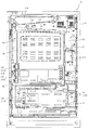
以下、本発明の第1実施形態について、添付図面を参照して説明する。図1は、第1実施形態におけるパチンコ機10の正面図であり、図2はパチンコ機10の遊技盤13の正面図であり、図3はパチンコ機10の背面図である。
<First Embodiment>
Hereinafter, a first embodiment of the present invention will be described with reference to the accompanying drawings. 1 is a front view of a
パチンコ機10は、図1に示すように、略矩形状に組み合わせた木枠により外殻が形成される外枠11と、その外枠11と略同一の外形形状に形成され外枠11に対して開閉可能に支持された内枠12とを備えている。外枠11には、内枠12を支持するために正面視(図1参照)左側の上下2カ所に金属製のヒンジ18が取り付けられ、そのヒンジ18が設けられた側を開閉の軸として内枠12が正面手前側へ開閉可能に支持されている。
As shown in FIG. 1, the
内枠12には、多数の釘や入賞口63,64等を有する遊技盤13(図2参照)が裏面側から着脱可能に装着される。この遊技盤13の前面を球が流下することにより弾球遊技が行われる。なお、内枠12には、球を遊技盤13の前面領域に発射する球発射ユニット112a(図6参照)やその球発射ユニット112aから発射された球を遊技盤13の前面領域まで誘導する発射レール(図示せず)等が取り付けられている。
A game board 13 (see FIG. 2) having a large number of nails, winning
内枠12の前面側には、その前面上側を覆う前面枠14と、その下側を覆う下皿ユニット15とが設けられている。前面枠14及び下皿ユニット15を支持するために正面視(図1参照)左側の上下2カ所に金属製のヒンジ19が取り付けられ、そのヒンジ19が設けられた側を開閉の軸として前面枠14及び下皿ユニット15が正面手前側へ開閉可能に支持されている。なお、内枠12の施錠と前面枠14の施錠とは、シリンダ錠20の鍵穴21に専用の鍵を差し込んで所定の操作を行うことでそれぞれ解除される。
On the front side of the
前面枠14は、装飾用の樹脂部品や電気部品等を組み付けたものであり、その略中央部には略楕円形状に開口形成された窓部14cが設けられている。前面枠14の裏面側には2枚の板ガラスを有するガラスユニット16が配設され、そのガラスユニット16を介して遊技盤13の前面がパチンコ機10の正面側に視認可能となっている。
The
前面枠14には、球を貯留する上皿17が前方へ張り出して上面を開放した略箱状に形成されており、この上皿17に賞球や貸出球などが排出される。上皿17の底面は正面視(図1参照)右側に下降傾斜して形成され、その傾斜により上皿17に投入された球が球発射ユニット112aへと案内される。また、上皿17の上面には、枠ボタン22が設けられている。この枠ボタン22は、例えば、後述する第3図柄表示装置81(図2参照)で表示される演出のステージを変更したり、スーパーリーチの演出内容を変更したりする場合などに、遊技者により操作される。
On the
ステージとは、第3図柄表示装置81に表示される各種演出に統一性を持たせた演出モードのことで、本パチンコ機10では「街中ステージ」,「空ステージ」,「島ステージ」の3つのステージが設けられている。そして、後述する第1入球口64a、または第2入球口64bへの入球(始動入賞)に伴って行われる変動演出やリーチ演出などの各種演出は、それぞれのステージに与えられたテーマに合わせて行われるように設計されている。ステージの変更は、変動演出が行われていない期間や高速変動中に遊技者によって枠ボタン22が操作された場合に行われ、枠ボタン22が操作される度に「街中ステージ」→「空ステージ」→「島ステージ」→「街中ステージ」→・・・の順で繰り返し変更される。また、電源投入後の直後は、初期ステージとして「街中ステージ」が設定される。
The stage is an effect mode in which the various effects displayed on the third
一方、第3図柄表示装置81には、ノーマルリーチ演出が開始された場合に、ノーマルリーチからスーパーリーチに発展させるときは、ノーマルリーチ中にスーパーリーチの演出態様の選択画面が表示されるように構成されており、その選択画面が表示されている間に、枠ボタン22が遊技者に操作されると、スーパーリーチ時の演出内容が変更される。
On the other hand, the 3rd
前面枠14には、その周囲(例えばコーナー部分)に各種ランプ等の発光手段が設けられている。これら発光手段は、大当たり時や所定のリーチ時等における遊技状態の変化に応じて、点灯又は点滅することにより発光態様が変更制御され、遊技中の演出効果を高める役割を果たす。窓部14cの周縁には、LED等の発光手段を内蔵した電飾部29〜33が設けられている。パチンコ機10においては、これら電飾部29〜33が大当たりランプ等の演出ランプとして機能し、大当たり時やリーチ演出時等には内蔵するLEDの点灯や点滅によって各電飾部29〜33が点灯または点滅して、大当たり中である旨、或いは大当たり一歩手前のリーチ中である旨が報知される。また、前面枠14の正面視(図1参照)左上部には、LED等の発光手段が内蔵され賞球の払い出し中とエラー発生時とを表示可能な表示ランプ34が設けられている。
The
また、右側の電飾部32下側には、前面枠14の裏面側を視認できるように裏面側より透明樹脂を取り付けて小窓35が形成され、遊技盤13前面の貼着スペースK1(図2参照)に貼付される証紙等はパチンコ機10の前面から視認可能とされている。また、パチンコ機10においては、より煌びやかさを醸し出すために、電飾部29〜33の周りの領域にクロムメッキを施したABS樹脂製のメッキ部材36が取り付けられている。
In addition, a
窓部14cの下方には、貸球操作部40が配設されている。貸球操作部40には、度数表示部41と、球貸しボタン42と、返却ボタン43とが設けられている。パチンコ機10の側方に配置されるカードユニット(球貸しユニット)(図示せず)に紙幣やカード等を投入した状態で貸球操作部40が操作されると、その操作に応じて球の貸出が行われる。具体的には、度数表示部41はカード等の残額情報が表示される領域であり、内蔵されたLEDが点灯して残額情報として残額が数字で表示される。球貸しボタン42は、カード等(記録媒体)に記録された情報に基づいて貸出球を得るために操作されるものであり、カード等に残額が存在する限りにおいて貸出球が上皿17に供給される。返却ボタン43は、カードユニットに挿入されたカード等の返却を求める際に操作される。なお、カードユニットを介さずに球貸し装置等から上皿17に球が直接貸し出されるパチンコ機、いわゆる現金機では貸球操作部40が不要となるが、この場合には、貸球操作部40の設置部分に飾りシール等を付加して部品構成は共通のものとしても良い。カードユニットを用いたパチンコ機と現金機との共通化を図ることができる。
A ball
上皿17の下側に位置する下皿ユニット15には、その中央部に上皿17に貯留しきれなかった球を貯留するための下皿50が上面を開放した略箱状に形成されている。下皿50の右側には、球を遊技盤13の前面へ打ち込むために遊技者によって操作される操作ハンドル51が配設され、かかる操作ハンドル51の内部には球発射ユニット112aの駆動を許可するためのタッチセンサ51aと、押下操作している期間中には球の発射を停止する押しボタン式の打ち止めスイッチ51bと、操作ハンドル51の回動操作量を電気抵抗の変化により検出する可変抵抗器(図示せず)とが内蔵されている。操作ハンドル51が遊技者によって右回りに回転操作されると、タッチセンサ51aがオンされると共に可変抵抗器の抵抗値が操作量に対応して変化し、操作ハンドル51の回動操作量に応じて変化する可変抵抗器の抵抗値に対応した強さで球が発射され、これにより遊技者の操作に対応した飛び量で遊技盤13の前面へ球が打ち込まれる。また、操作ハンドル51が遊技者により操作されていない状態においては、タッチセンサ51aおよび打ち止めスイッチ51bがオフとなっている。
In the
下皿50の正面下方部には、下皿50に貯留された球を下方へ排出する際に操作するための球抜きレバー52が設けられている。この球抜きレバー52は、常時、右方向に付勢されており、その付勢に抗して左方向へスライドさせることにより、下皿50の底面に形成された底面口が開口して、その底面口から球が自然落下して排出される。かかる球抜きレバー52の操作は、通常、下皿50の下方に下皿50から排出された球を受け取る箱(一般に「千両箱」と称される)を置いた状態で行われる。下皿50の右方には、上述したように操作ハンドル51が配設され、下皿50の左方には灰皿53が取り付けられている。
In the lower part of the front of the
図2に示すように、遊技盤13は、正面視略正方形状に切削加工した木製のベース板60に、球案内用の多数の釘や風車およびレール61,62、一般入賞口63、第1入球口64a、第2入球口64b、可変入賞装置65、可変表示装置ユニット80等を組み付けて構成され、その周縁部が内枠12の裏面側に取り付けられる。一般入賞口63、第1入球口64a、第2入球口64b、可変入賞装置65、可変表示装置ユニット80は、ルータ加工によってベース板60に形成された貫通穴に配設され、遊技盤13の前面側から木ネジ等により固定されている。また、遊技盤13の前面中央部分は、前面枠14の窓部14c(図1参照)を通じて内枠12の前面側から視認することができる。以下に、主に図2を参照して、遊技盤13の構成について説明する。
As shown in FIG. 2, the
遊技盤13の前面には、帯状の金属板を略円弧状に屈曲加工して形成した外レール62が植立され、その外レール62の内側位置には外レール62と同様に帯状の金属板で形成した円弧状の内レール61が植立される。この内レール61と外レール62とにより遊技盤13の前面外周が囲まれ、遊技盤13とガラスユニット16(図1参照)とにより前後が囲まれることにより、遊技盤13の前面には、球の挙動により遊技が行われる遊技領域が形成される。遊技領域は、遊技盤13の前面であって2本のレール61,62と円弧部材70とにより区画して形成される略円形状の領域(入賞口等が配設され、発射された球が流下する領域)である。
An
2本のレール61,62は、球発射ユニット112a(図5参照)から発射された球を遊技盤13上部へ案内するために設けられたものである。内レール61の先端部分(図2の左上部)には戻り球防止部材68が取り付けられ、一旦、遊技盤13の上部へ案内された球が再度球案内通路内に戻ってしまうといった事態が防止される。外レール62の先端部(図2の右上部)には、球の最大飛翔部分に対応する位置に返しゴム69が取り付けられ、所定以上の勢いで発射された球は、返しゴム69に当たって、勢いが減衰されつつ中央部側へ跳ね返される。また、内レール61の右下側の先端部と外レール62の右上側の先端部との間には、レール間を繋ぐ円弧を内面側に設けて形成された樹脂製の円弧部材70がベース板60に打ち込んで固定されている。
The two
本パチンコ機10では、球が第1入球口64a、または第2入球口64bへ入球した場合に特別図柄(第1図柄)の抽選が行われ、球が普通入球口67を通過した場合に普通図柄(第2図柄)の抽選が行われる。第1入球口64a、または第2入球口64bへの入球に対して行われる特別図柄の抽選では、特別図柄の大当たりか否かの当否判定が行われると共に、特別図柄の大当たりと判定された場合にはその大当たり種別の判定も行われる。特別図柄の大当たりになると、パチンコ機10が特別遊技状態へ移行すると共に、通常時には閉鎖されている特定入賞口65aが所定時間(例えば、30秒経過するまで、或いは、球が10個入賞するまで)開放され、その開放が複数回繰り返される。その結果、特定入賞口65aに多量の球が入賞するので、通常時より多量の賞球の払い出しが行われる。特別図柄の大当たり種別としては、「大当たりA」〜「大当たりD」の4種類が設けられており、特別遊技状態の終了後には大当たり終了後の付加価値として、これらの大当たり種別に応じた遊技上の価値(遊技価値)が遊技者に付与される。詳細については後述するが、例えば、大当たり種別が「大当たりA」であった場合は、大当たり終了後に、特別図柄の抽選が100回行われるまで普通図柄の時短状態が継続するという遊技価値が付与され、大当たり種別が「大当たりB」であった場合は、大当たり終了後に特別図柄の高確率状態に移行するという遊技価値が付与される。
In this
また、特別図柄(第1図柄)の抽選が行われると、第1図柄表示装置37において特別図柄の変動表示が開始されて、所定時間(例えば、4秒〜30秒など)が経過した後に、抽選結果を示す特別図柄が停止表示される。第1図柄表示装置37において変動表示が行われている間に球が第1入球口64a、または第2入球口64bへ入球すると、その入球回数は最大4回まで保留され、その保留球数が第1図柄表示装置37により示されると共に、第3図柄表示装置81においても示される。第1図柄表示装置37において変動表示が終了した場合に、第1入球口64a、または第2入球口64bについての保留球数が残っていれば、次の特別図柄の抽選が行われると共に、その抽選に応じた変動表示が開始される。なお、パチンコ機10が特別遊技状態へ移行すると開閉される特定入賞口65aは、第1入球口64aの直ぐ下に設けられている。よって、特別遊技状態中は、遊技者が特定入賞口65aに入賞させようとして球を打つので、第1入球口64aにも球が多く入球する。従って、殆どの場合、パチンコ機10が特別遊技状態に移行している間に、第1入球口64aについての保留球数は最大(4回)になる。
In addition, when the special symbol (the first symbol) is drawn, the special symbol variable display is started on the first
一方、普通入球口67における球の通過に対して行われる普通図柄の抽選では、普通図柄の当たりか否かの当否判定が行われる。普通図柄の当たりになると、所定時間(例えば、0.2秒または1秒)だけ第2入球口64bに付随する電動役物が開放され、第2入球口64bへ球が入球し易い状態になる。つまり、普通図柄の当たりになると、球が第2入球口64bへ入球し易くなり、その結果、特別図柄の抽選が行われ易くなる。
On the other hand, in the normal symbol lottery performed for the passage of the ball at the
また、普通図柄(第2図柄)の抽選が行われると、第2図柄表示装置83において普通図柄の変動表示が開始されて、所定時間(例えば、3秒や30秒など)が経過した後に、抽選結果を示す普通図柄が停止表示される。第2図柄表示装置83において変動表示が行われている間に球が普通入球口67を通過すると、その通過回数は最大4回まで保留され、その保留球数が第1図柄表示装置37により表示されると共に、第2図柄保留ランプ84においても示される。第2図柄表示装置83において変動表示が終了した場合に、普通入球口67についての保留球数が残っていれば、次の普通図柄の抽選が行われると共に、その抽選に応じた変動表示が開始される。
In addition, when the normal symbol (the second symbol) is drawn, the normal symbol variation display is started on the second
上述したように、特別図柄の大当たり種別としては、「大当たりA」〜「大当たりD」の4種類が設けられている。 As described above, there are four types of jackpot types for special symbols: “Big Jack A” to “Big Jack D”.
「通常大当たり」になると、ラウンド数が16ラウンドの特別遊技状態(16ラウンド大当たり)となるが、大当たり終了後には何らの付加価値も付与されることがない。即ち、大当たり終了後は特別図柄の低確率状態へ移行し、「普通図柄の時短状態」(普通図柄の時短中)へ移行することもない。 When “ordinary jackpot” is reached, a special gaming state with 16 rounds (16 round jackpot) is entered, but no added value is given after the jackpot ends. That is, after the jackpot ends, the special symbol shifts to a low probability state and does not shift to the “normal symbol time-short state” (ordinary symbol time-short state).
「大当たりA(時短大当たり)」になると、ラウンド数が8ラウンドの特別遊技状態(8ラウンド大当たり)となり、その後、大当たり終了後の付加価値として、「普通図柄の時短状態」(普通図柄の時短中)へ移行する。具体的には、大当たりの終了後から特別図柄の抽選が100回終了するまでの間は普通図柄の当たり確率がアップする。なお、本実施形態では、特別図柄の抽選回数で普通図柄の時短状態が継続する期間を規定しているが、例えば、特別図柄の変動が終了する回数で規定してもよい。 When the jackpot A (short-term jackpot) is reached, the number of rounds becomes a special game state with eight rounds (8 rounds jackpot). ) Specifically, the probability of winning a normal symbol increases after the end of the jackpot until the special symbol lottery ends 100 times. In the present embodiment, the period in which the short time state of the normal symbol continues is defined by the number of lotteries for the special symbol, but may be defined by the number of times the variation of the special symbol is completed, for example.
また、「大当たりB(確変大当たり)」、「大当たりC(潜伏確変大当たり)」、または「大当たりD(レア潜伏確変大当たり)」に当選すると、いずれもラウンド数が8ラウンドの特別遊技状態(8ラウンド大当たり)となり、その後大当たり終了後の付加価値として、「特別図柄の高確率状態」へ移行する。また、「大当たりB(確変大当たり)」に当選した場合は、遊技者に対して「特別図柄の高確率状態」へと移行したことが報知されるが、「大当たりC(潜伏確変大当たり)」、または「大当たりD(レア潜伏確変大当たり)」では報知が行われない。よって、「特別図柄の高確率状態」へと移行したことが報知されなかったとしても、遊技者に対して、「大当たりC(潜伏確変大当たり)」、または「大当たりD(レア潜伏確変大当たり)」に当選していたことを期待させることができる。即ち、「特別図柄の高確率状態」となっていることを期待させることができる。 In addition, if you win a “big hit B (probable big jackpot)”, “big hit C (latent probability big jackpot)” or “big hit D (rare latent big jackpot)”, all of them are in a special gaming state with 8 rounds (8 rounds) After that, it shifts to the “high probability state of special symbol” as added value after the end of the jackpot. In addition, when winning “big hit B (probability change big win)”, the player is informed that the game has shifted to the “high probability state of special symbol”, but “big hit C (latency probability change big hit)”, Or, the “big hit D (rare latency probability change big hit)” is not notified. Therefore, even if it is not notified that the transition to the “high probability state of the special symbol” is made, it is possible to give the player a “big hit C (latency probability variation big hit)” or “big hit D (rare latent probability variation big hit)”. Can be expected to have won. That is, it can be expected that the state is a “high probability state of special symbol”.
更に、「大当たりC(潜伏確変大当たり)」に当選した場合は、大当たりが報知される場合に選択される変動演出の内容や、大当たりの終了後、特別図柄の外れが報知される場合に選択される変動パターン演出の表示内容は、「大当たりA(時短大当たり)」と同じ内容となる。つまり、「大当たりA(時短大当たり)」に当選したのか「大当たりC(潜伏確変大当たり)」に当選したのかを判別することが困難となるように構成されている。一方、「大当たりD(レア潜伏確変大当たり)」に当選した場合は、「大当たりA(時短大当たり)」や「大当たりB(潜伏確変大当たり)」に当選した場合に比較して、大当たりが報知される際や、大当たり終了後に特別図柄の外れが報知される際に、期待度の高い態様の変動パターン演出が選択されやすくなるように構成されている。よって、「特別図柄の高確率状態」へと移行したことが報知されなかったとしても、期待度の高い態様の変動パターン演出が選択されることで、「大当たりD(レア潜伏確変大当たり)」に当選したことを期待させることができ、遊技者の遊技に対する興趣を向上させることができる。 In addition, when winning the jackpot C (latency probability change jackpot), it is selected when the contents of the fluctuating effect selected when the jackpot is notified or when the special symbol is missed after the jackpot ends. The display content of the fluctuation pattern effect is the same as “big hit A (short-term big hit)”. In other words, it is difficult to determine whether “big hit A (short-term big hit)” or “big hit C (latency probability variation big hit)” is won. On the other hand, if you win the jackpot D (rare latent probability variation jackpot), you will be notified of the jackpot compared to the case where you win the jackpot A (short-term jackpot) or jackpot B (latency probability variation jackpot) At the time, when a special symbol losing is notified after the end of the jackpot, a variation pattern effect having a high expectation is easily selected. Therefore, even if it is not informed that the transition to the “high probability state of the special symbol” is made, it is possible to select “big hit D (rare latency probability big hit)” by selecting a variation pattern effect with a high expectation. It can be expected that the player has won, and the player's interest in games can be improved.
ここで、「特別図柄の高確率状態」とは、特別図柄の大当たり確率がアップした状態、いわゆる特別図柄の高確率状態(特別図柄の確変中)をいい、換言すれば、特別遊技状態(大当たり)へ移行し易い遊技の状態のことである。対して、「特別図柄の高確率状態」でない場合を「特別図柄の低確率状態」といい、これは特別図柄の確変状態よりも大当たり確率が低い状態、即ち、特別図柄の大当たり確率が通常の状態(特別図柄の通常状態)のことを示す。また、「普通図柄の時短状態」(普通図柄の時短中)とは、普通図柄の当たり確率がアップして、第2入球口64bへ球が入球し易い遊技の状態のことをいう。対して、「普通図柄の時短状態」でない時を「普通図柄の通常状態」といい、これは普通図柄の当たり確率が通常の状態、即ち、時短中よりも当たり確率が低い状態のことを示す。
Here, the “high probability state of a special symbol” means a state in which the jackpot probability of a special symbol is increased, that is, a so-called special symbol high probability state (during special symbol change), in other words, a special gaming state (a jackpot) ) Is a game state that is easy to shift to. On the other hand, a case that is not a “high probability state of a special symbol” is called a “low probability state of a special symbol”, which has a lower probability of jackpot than the probability variation state of a special symbol, that is, the jackpot probability of a special symbol is normal. Indicates the state (normal state of special symbol). The “normal symbol time-short state” (ordinary symbol time-short state) means a game state in which the probability of hitting the normal symbol increases and the ball easily enters the
以後、特別図柄の大当たり終了後からパチンコ機10が普通図柄の時短状態になっている期間、即ち、「大当たりA」が終了してから、特別図柄の抽選が100回終了するまでの間のことを、普通図柄の時短期間と称す。なお、本実施形態のパチンコ機10では、特別図柄の確変中にも普通図柄の当たり確率がアップする。上述の通り、「大当たりA」の場合、普通図柄の当たり確率がアップするのは特別図柄の抽選が100回終了するまでに限定されていたが、特別図柄の高確率状態へと移行した場合は、次に大当たりに当選するまで普通図柄の当たり確率がアップした状態のまま維持される。即ち、「大当たりB」〜「大当たりD」に当選した場合は、持ち玉を減らすことなく次の大当たりを待つことができるので、遊技者にとって有利な大当たりとなる。このように、本実施形態のパチンコ機10には、大当たり状態や、普通図柄の時短状態、特別図柄の確変状態等の様々な遊技状態が設けられており、遊技者の興趣向上が図られている。
After that, after the special symbol jackpot ends, the period when the
上述したように、本実施形態では、「大当たりA」に当選した場合に、普通図柄の時短期間は100回としていたが、これに限られるものではない。例えば、普通図柄の時短期間として、20回や150回を選択してもよい。また、特別図柄の抽選回数に代えて、所定時間(例えば、2分から5分など)が経過するまで、普通図柄の時短状態が継続されるようにしても良い。また、「普通図柄の時短状態」とする代わりに、第2入球口64bに付随する電動役物(図示せず)を開放する時間を長くしたり、1回の普通図柄の当たりで電動役物を開放する回数を多くしたりしても良い。また、ラウンド数や特定入賞口(大開放口)65aの閉鎖条件は、本実施形態の態様に限られるものではなく、例えば、4ラウンドの大当たりや16ラウンドの大当たりを設けてもよいし、特定入賞口(大開放口)65aの閉鎖条件として、例えば、「3秒経過するまで、或いは、球が10個入賞するまで」という条件や、「10秒経過するまで、或いは、球が5個入賞するまで」という条件の大当たりを設けてもよい。また、本実施形態では、大当たり終了後に、「特別図柄の高確率状態」、または「普通図柄の時短状態」のうちいずれかの状態へと移行するように構成しているが、大当たりが終了してから特別図柄の抽選が所定回数(例えば、4回)終了するまでの間は必ず「特別図柄の高確率状態」となるように構成し、所定回数の特別図柄の抽選が終了した後で、「特別図柄の低確率状態」へ移行させると共に、「普通図柄の時短状態」、または「普通図柄の通常状態」となるように構成しても良い。
As described above, in the present embodiment, when the “big hit A” is won, the short time period of the normal symbol is 100 times, but this is not a limitation. For example, 20 times or 150 times may be selected as a short time period of a normal symbol. Further, instead of the number of times of drawing a special symbol, the normal symbol time-saving state may be continued until a predetermined time (for example, 2 to 5 minutes) elapses. In addition, instead of setting the “normal symbol time-short state”, the time required to open the electric accessory (not shown) associated with the
更に、本実施形態では大当たりに当選した際の遊技状態によらず、大当たり終了後に遊技者に与えられる付加価値を共通としているが、大当たりに当選した際の遊技状態に応じて、大当たり終了後に遊技者に与えられる付加価値を異ならせてもよい。例えば、普通図柄の時短状態中に「大当たりA」に当選した場合は、普通図柄の時短期間を100回とし、普通図柄の通常状態中に「大当たりA」に当選した場合は、普通図柄の時短期間を50回としてもよい。 Furthermore, in this embodiment, the added value given to the player after the jackpot is shared is common regardless of the gaming state when the jackpot is won, but the game after the jackpot ends depending on the gaming state when the jackpot is won. The added value given to the person may be different. For example, if you win the “big hit A” during the normal symbol time-saving state, the normal symbol time-saving period is 100 times, and if you win the “big hit A” during the normal symbol normal state, The period may be 50 times.
遊技領域の正面視右側上部(図2の右側上部)には、発光手段である複数の発光ダイオード(以下、「LED」と略す。)37aと7セグメント表示器37bとが設けられた第1図柄表示装置37が配設されている。第1図柄表示装置37は、後述する主制御装置110で行われる各制御に応じた表示がなされるものであり、主にパチンコ機10の遊技状態の表示が行われる。複数のLED37aは、第1入球口64a、または第2入球口64bへの入球(始動入賞)に伴って行われる特別図柄の抽選が実行中であるか否かを点灯状態により示すことによって変動表示を行ったり、変動終了後の停止図柄として、その特別図柄の抽選結果に応じた特別図柄(第1図柄)を点灯状態により示したり、第1入球口64a、または第2入球口64bに入球した球のうち変動が未実行である球(保留球)の数である保留球数を点灯状態により示すものである。
A first pattern provided with a plurality of light emitting diodes (hereinafter abbreviated as “LEDs”) 37a and a 7-
この第1図柄表示装置37において特別図柄(第1図柄)の変動表示が行われている間に球が第1入球口64a、または第2入球口64bへ入球した場合、その入球回数は最大4回まで保留され、その保留球数は第1図柄表示装置37により示されると共に、第3図柄表示装置81においても示される。なお、本実施形態においては、第1入球口64a、または第2入球口64bへの入球は、最大4回まで保留されるように構成したが、最大保留回数は4回に限定されるものでなく、3回以下、又は、5回以上の回数(例えば、8回)に設定しても良い。また、第1入球口64aへの入球と、第2入球口64bへの入球をそれぞれ4回まで保留されるように構成してもよい。また、保留球に応じて変動を実行させる場合に、入球口の種別を考慮せずに入球があった順番に変動を実行させても良いし、保留球が存在する場合に、第2入球口64bへの入球を優先して実行させてもよい。また、第1入球口64aと第2入球口64bとで大当たりの当選確率や、各大当たり種別の選択比率を変更してもよい。
When a ball enters the
7セグメント表示器37bは、大当たり中のラウンド数やエラー表示を行うものである。なお、LED37aは、それぞれのLEDの発光色(例えば、赤、緑、青)が異なるよう構成され、その発光色の組み合わせにより、少ないLEDでパチンコ機10の各種遊技状態(特別図柄の高確率状態や、普通図柄の時短中など)を表示することができる。また、LED37aには、変動終了後の停止図柄として特別図柄の抽選結果が大当たりであるか否かが示されるだけでなく、大当たりである場合はその大当たり種別(「大当たりA」〜「大当たりD」)に応じた特別図柄(第1図柄)が示される。
The 7-
また、遊技領域には、球が入賞することにより5個から15個の球が賞球として払い出される複数の一般入賞口63が配設されている。また、遊技領域の中央部分には、可変表示装置ユニット80が配設されている。可変表示装置ユニット80には、液晶ディスプレイ(以下単に「表示装置」と略す。)で構成された第3図柄表示装置81と、LEDで構成された第2図柄表示装置83とが設けられている。この可変表示装置ユニット80には、第3図柄表示装置81の外周を囲むようにして、センターフレーム86が配設されている。
The game area is provided with a plurality of general winning
第3図柄表示装置81は、第1図柄表示装置37の表示に応じた装飾的な表示を行うものである。例えば、第1入球口64a、または第2入球口64bへ球が入球(始動入賞)すると、それをトリガとして、第1図柄表示装置37において特別図柄(第1図柄)の変動表示が実行される。更に、第3図柄表示装置81では、その特別図柄の変動表示に同期して、その特別図柄の変動表示に対応する第3図柄の変動表示が行われる。
The third
第3図柄表示装置81は、8インチサイズの大型の液晶ディスプレイで構成されるものであり、後述する表示制御装置114によって表示内容が制御されることにより、例えば左、中及び右の3つの図柄列が表示される。各図柄列は複数の図柄によって構成され、これらの図柄が図柄列毎に縦スクロールして第3図柄表示装置81の表示画面上にて第3図柄が可変表示されるようになっている。本実施形態では、主制御装置110の制御に伴った遊技状態の表示が第1図柄表示装置37で行われるのに対して、第3図柄表示装置81はその第1図柄表示装置37の表示に応じた装飾的な表示が行われる。なお、表示装置に代えて、例えば、リール等を用いて第3図柄表示装置81を構成するようにしても良い。
The third
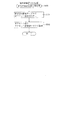
ここで、図4を参照して、第3図柄表示装置81の表示内容について説明する。図4は、第3図柄表示装置81の表示画面を説明するための図面である。図4(a)は、表示画面の領域区分設定と有効ライン設定とを模式的に示した図であり、図4(b)は、実際の表示画面を例示した図である。
Here, with reference to FIG. 4, the display content of the 3rd
第3図柄は、「0」から「9」の数字を付した10種類の主図柄によって構成されている。また、本実施形態のパチンコ機10においては、後述する主制御装置110(図5参照)により行われる特別図柄の抽選結果が大当たりであった場合に、同一の主図柄が揃う変動表示が行われ、その変動表示が終わった後に大当たりが発生するよう構成されている。一方、特別図柄の抽選結果が外れであった場合は、同一の主図柄が揃わない変動表示が行われる。
The third symbol is composed of ten kinds of main symbols with numbers “0” to “9”. Further, in the
例えば、特別図柄の抽選結果が「大当たりA」、「大当たりC」、「大当たりD」のいずれかであれば、偶数番号である「0,2,4,6,8」が付加された主図柄が揃う変動表示が行われる。また、「大当たりB」であれば、奇数番号である「1,3,5,7,9」が付加された主図柄が揃う変動表示が行われる。一方、特別図柄の抽選結果が外れであれば、同一番号の主図柄が揃わない変動表示が行われる。このように構成することにより、揃った主図柄を確認するだけで大当たり種別を認識することができる。 For example, if the lottery result of the special symbol is any one of “Big jackpot A”, “Big jackpot C”, and “Big jackpot D”, the main symbol to which the even number “0, 2, 4, 6, 8” is added. Is displayed. If “big hit B” is selected, a variable display is performed in which the main symbols to which odd numbers “1, 3, 5, 7, 9” are added are arranged. On the other hand, if the lottery result of the special symbol is off, the variable display in which the main symbols of the same number are not aligned is performed. By configuring in this way, it is possible to recognize the jackpot type only by confirming the main symbols that are aligned.
図4(a)に示すように、第3図柄表示装置81の表示画面は、大きくは上下に2分割され、上側の4/5が第3図柄を変動表示する主表示領域Dm、それ以外の下側の1/5が保留球数を表示する副表示領域Dsとなっている。
As shown in FIG. 4 (a), the display screen of the third
主表示領域Dmは、左・中・右の3つの表示領域Dm1〜Dm3に区分けされており、その3つの表示領域Dm1〜Dm3に、それぞれ3つの図柄列Z1,Z2,Z3が表示される。各図柄列Z1〜Z3には、上述した第3図柄が規定の順序で表示される。即ち、各図柄列Z1〜Z3には、数字の昇順または降順に主図柄が配列され、図柄列Z1〜Z3毎に周期性をもって上から下へとスクロールして変動表示が行われる。特に、左図柄列Z1においては主図柄の数字が降順に現れるように配列され、中図柄列Z2及び右図柄列Z3においては主図柄の数字が昇順に現れるように配列されている。 The main display area Dm is divided into three display areas Dm1 to Dm3 of left, middle, and right, and three symbol rows Z1, Z2, and Z3 are displayed in the three display areas Dm1 to Dm3, respectively. In each symbol row Z1 to Z3, the above-described third symbols are displayed in a prescribed order. That is, the main symbols are arranged in ascending or descending numbers in the symbol rows Z1 to Z3, and the symbol rows Z1 to Z3 are scrolled from the top to the bottom with periodicity to perform the variable display. In particular, the left symbol row Z1 is arranged so that the numbers of the main symbols appear in descending order, and the middle symbol row Z2 and the right symbol row Z3 are arranged so that the numbers of the main symbols appear in ascending order.
また、主表示領域Dmには、図柄列Z1〜Z3毎に上・中・下の3段に第3図柄が表示される。この主表示領域Dmの中段部が有効ラインL1として設定されており、毎回の遊技に際して、左図柄列Z1→右図柄列Z3→中図柄列Z2の順に、有効ラインL1上に第3図柄が停止表示される。その第3図柄の停止時に有効ラインL1上に大当たり図柄の組合せ(本実施形態では、同一の主図柄の組合せ)で揃えば大当たりとして大当たり動画が表示される。 In the main display area Dm, the third symbols are displayed in the upper, middle, and lower three rows for each of the symbol rows Z1 to Z3. The middle part of the main display area Dm is set as the active line L1, and in each game, the third symbol stops on the effective line L1 in the order of the left symbol row Z1, the right symbol row Z3, and the middle symbol row Z2. Is displayed. If the combination of jackpot symbols (the same main symbol combination in this embodiment) is arranged on the effective line L1 when the third symbol is stopped, a jackpot moving image is displayed as a jackpot.
一方、副表示領域Dsは、主表示領域Dmよりも下方に横長に設けられている。この副表示領域Dsには、第1入球口64a、または第2入球口64bに入球した球のうち変動が未実行である球(保留球)の数である保留球数が表示される。
On the other hand, the sub display area Ds is provided horizontally long below the main display area Dm. In this sub display area Ds, the number of reserved balls, which is the number of balls that have not been changed (holding balls) among the balls that have entered the
実際の表示画面では、図4(b)に示すように、主表示領域Dmに第3図柄の主図柄が合計9個表示される。第3図柄表示装置81(第1図柄表示装置37)にて変動表示が行われている間に球が第1入球口64a、または第2入球口64bへ入球した場合、その入球回数は最大4回まで保留され、その保留球数は第1図柄表示装置37により示されると共に、副表示領域Dsにおいても示される。副表示領域Dsには、保留球数1球につき1つの保留球数図柄が表示され、その保留球数図柄の表示数に応じて、保留球数が表示される。即ち、副表示領域Dsに1つの保留球数図柄が表示されている場合は、保留球数が1球であることを示し、4つの保留球数図柄が表示されている場合は、保留球数が4球であることを示す。また、副表示領域Dsに保留球数図柄が表示されていない場合は、保留球数が0球である、即ち、保留球が存在しないことを示す。
On the actual display screen, as shown in FIG. 4B, a total of nine main symbols of the third symbol are displayed in the main display area Dm. When a ball enters the
なお、本実施形態においては、第1入球口64a、または第2入球口64bへの入球は、最大4回まで保留されるように構成したが、最大保留球数は4回に限定されるものでなく、3回以下、又は、5回以上の回数(例えば、8回)に設定しても良い。また、副表示領域Dsにおける保留球数図柄の表示に代えて、保留球数を第3図柄表示装置81の一部に数字で、或いは、4つに区画された領域を保留球数分だけ異なる態様(例えば、色や点灯パターン)にして表示するようにしても良い。また、第1図柄表示装置37により保留球数が示されるので、第3図柄表示装置81に保留球数を表示させないものとしてもよい。更に、可変表示装置ユニット80に、保留球数を示す保留ランプを最大保留数分の4つ設け、点灯状態の保留ランプの数に応じて、保留球数を表示するものとしてもよい。
In the present embodiment, the entrance to the
図2に戻って、説明を続ける。第2図柄表示装置83は、球が普通入球口67を通過することに伴って行われる普通図柄の抽選が実行中であるか否かを点灯状態により示すことによって変動表示を行ったり、変動終了後の停止図柄として、その普通図柄の抽選結果に応じた普通図柄(第2図柄)を点灯状態により示したりするものである。
Returning to FIG. 2, the description will be continued. The second
より具体的には、第2図柄表示装置83では、球が普通入球口67を通過する毎に、第2図柄としての「○」の図柄と「×」の図柄とを交互に点灯させる変動表示が行われる。パチンコ機10は、第2図柄表示装置83における変動表示が所定図柄(本実施形態においては「○」の図柄)で停止すると、第2入球口64bに付随する電動役物が所定時間だけ作動状態となり(開放される)、その結果、第2入球口64bに球が入り易い状態となるように構成されている。球が普通入球口67を通過した通過回数は最大4回まで保留され、その保留球数が上述した第1図柄表示装置37により表示されると共に第2図柄保留ランプ84においても点灯表示される。第2図柄保留ランプ84は、最大保留数分の4つ設けられ、第3図柄表示装置81の下方に左右対称に配設されている。
More specifically, in the second
なお、普通図柄(第2図柄)の変動表示は、本実施形態のように、第2図柄表示装置83において複数のランプの点灯と非点灯を切り換えることにより行うものの他、第1図柄表示装置37及び第3図柄表示装置81の一部を使用して行うようにしても良い。同様に、第2図柄保留ランプ84の点灯を第3図柄表示装置81の一部で行うようにしても良い。また、普通入球口67における球の通過は、第1入球口64a、および第2入球口64bと同様に、最大保留球数は4回に限定されるものでなく、3回以下、又は、5回以上の回数(例えば、8回)に設定しても良い。また、第1図柄表示装置37により保留球数が示されるので、第2図柄保留ランプ84により点灯表示を行わないものとしても良い。
The normal symbol (second symbol) variable display is performed by switching on and off of a plurality of lamps in the second
可変表示装置ユニット80の下方には、球が入球し得る第1入球口64aが配設されている。この第1入球口64aへ球が入球すると遊技盤13の裏面側に設けられる第1入球口スイッチ(図示せず)がオンとなり、その第1入球口スイッチのオンに起因して主制御装置110で特別図柄の抽選がなされ、その抽選結果に応じた表示が第1図柄表示装置37のLED37aで示される。また、第1入球口64aは、球が入球すると5個の球が賞球として払い出される入賞口の1つにもなっている。
Below the
第1入球口64aの下方には、球が入球し得る第2入球口64bが配設されている。この第2入球口64bへ球が入球すると遊技盤13の裏面側に設けられる第2入球口スイッチ(図示せず)がオンとなり、その第2入球口スイッチのオンに起因して主制御装置110で特別図柄の抽選がなされ、その抽選結果に応じた表示が第1図柄表示装置37のLED37aで示される。また、第2入球口64bは、第1入球口64aと同様に、球が入球すると5個の球が賞球として払い出される入賞口の1つにもなっている。この第2入球口64bは、上側が第1入球口64aにより遮蔽されているため、通常時は球を入球させることが困難となっている。上述の通り、普通図柄の当たりになることで、第2入球口64bに付随する電動役物が開放され、第2入球口64bへ球が入球し易い状態になる。即ち、普通図柄の当たりとなりやすい特別図柄の確変中や、普通図柄の時短期間中に第2入球口64bへ球が入球し易くなるように構成されている。
A
第2入球口64bの下方には可変入賞装置65が配設されており、その略中央部分に横長矩形状の特定入賞口(大開放口)65aが設けられている。パチンコ機10においては、主制御装置110で行われる特別図柄の抽選が大当たりとなると、所定時間(変動時間)が経過した後に、大当たりの停止図柄となるよう第1図柄表示装置37のLED37aを点灯させると共に、その大当たりに対応した第3図柄の停止図柄を第3図柄表示装置81に表示させて、大当たりの発生が示される。その後、通常時より多量の賞球の払い出しが行われる特別遊技状態に遊技状態が遷移する。この特別遊技状態として、通常時には閉鎖されている特定入賞口65aが、所定時間(30秒経過するまで、若しくは、球が10個入賞するまで、又は、0.5秒経過するまで、若しくは、球が10個入賞するまで)開放される。
A variable winning
この特定入賞口65aは、所定時間が経過すると閉鎖され、その閉鎖後、再度、その特定入賞口65aが所定時間開放される。この特定入賞口65aの開閉動作は、大当たり種別に応じた回数だけ繰り返し可能にされている。この開閉動作が行われている状態が、遊技者にとって有利な特別遊技状態の一形態であり、遊技者には、遊技上の価値(遊技価値)の付与として通常時より多量の賞球の払い出しが行われる。
The
可変入賞装置65は、具体的には、特定入賞口65aを覆う横長矩形状の開閉板と、その開閉板の下辺を軸として前方側に開閉駆動するための大開放口ソレノイド(図示せず)とを備えている。特定入賞口65aは、通常時は、球が入賞できないか又は入賞し難い閉状態になっている。大当たりの際には大開放口ソレノイドを駆動して開閉板を前面下側に傾倒し、球が特定入賞口65aに入賞しやすい開状態を一時的に形成し、その開状態と通常時の閉状態との状態を交互に繰り返すように作動する。
Specifically, the variable winning
なお、特別遊技状態は上記した形態に限定されるものではない。特定入賞口65aとは別に開閉される大開放口を遊技領域に設け、第1図柄表示装置37において大当たりに対応したLED37aが点灯した場合に、特定入賞口65aが所定時間開放され、その特定入賞口65aの開放中に、球が特定入賞口65a内へ入賞することを契機として特定入賞口65aとは別に設けられた大開放口が所定時間、所定回数開放される遊技状態を特別遊技状態として形成するようにしても良い。
The special gaming state is not limited to the above-described form. When the game area is provided with a large opening that is opened and closed separately from the specific winning
遊技盤13の下側における左右の隅部には、証紙や識別ラベル等を貼着するための貼着スペースK1,K2が設けられ、貼着スペースK1に貼られた証紙等は、前面枠14の小窓35(図1参照)を通じて視認することができる。
Adhesive spaces K1, K2 for adhering certificate papers, identification labels, etc. are provided at the left and right corners on the lower side of the
更に、遊技盤13には、アウト口66が設けられている。いずれの入賞口63,64,65aにも入球しなかった球はアウト口66を通って図示しない球排出路へと案内される。遊技盤13には、球の落下方向を適宜分散、調整等するために多数の釘が植設されているとともに、風車等の各種部材(役物)が配設されている。
Further, the
図3に示すように、パチンコ機10の背面側には、制御基板ユニット90,91と、裏パックユニット94とが主に備えられている。制御基板ユニット90は、主基板(主制御装置110)と音声ランプ制御基板(音声ランプ制御装置113)と表示制御基板(表示制御装置114)とが搭載されてユニット化されている。制御基板ユニット91は、払出制御基板(払出制御装置111)と発射制御基板(発射制御装置112)と電源基板(電源装置115)とカードユニット接続基板116とが搭載されてユニット化されている。
As shown in FIG. 3,
裏パックユニット94は、保護カバー部を形成する裏パック92と払出ユニット93とがユニット化されている。また、各制御基板には、各制御を司る1チップマイコンとしてのMPU、各種機器との連絡をとるポート、各種抽選の際に用いられる乱数発生器、時間計数や同期を図る場合などに使用されるクロックパルス発生回路等が、必要に応じて搭載されている。
The
なお、主制御装置110、音声ランプ制御装置113及び表示制御装置114、払出制御装置111及び発射制御装置112、電源装置115、カードユニット接続基板116は、それぞれ基板ボックス100〜104に収納されている。基板ボックス100〜104は、ボックスベースと該ボックスベースの開口部を覆うボックスカバーとを備えており、そのボックスベースとボックスカバーとが互いに連結されて、各制御装置や各基板が収納される。
The
また、基板ボックス100(主制御装置110)及び基板ボックス102(払出制御装置111及び発射制御装置112)は、ボックスベースとボックスカバーとを封印ユニット(図示せず)によって開封不能に連結(かしめ構造による連結)している。また、ボックスベースとボックスカバーとの連結部には、ボックスベースとボックスカバーとに亘って封印シール(図示せず)が貼着されている。この封印シールは、脆性な素材で構成されており、基板ボックス100,102を開封するために封印シールを剥がそうとしたり、基板ボックス100,102を無理に開封しようとしたりすると、ボックスベース側とボックスカバー側とに切断される。よって、封印ユニット又は封印シールを確認することで、基板ボックス100,102が開封されたかどうかを知ることができる。
Further, the substrate box 100 (main control device 110) and the substrate box 102 (dispensing
払出ユニット93は、裏パックユニット94の最上部に位置して上方に開口したタンク130と、タンク130の下方に連結され下流側に向けて緩やかに傾斜するタンクレール131と、タンクレール131の下流側に縦向きに連結されるケースレール132と、ケースレール132の最下流部に設けられ、払出モータ216(図5参照)の所定の電気的構成により球の払出を行う払出装置133とを備えている。タンク130には、遊技ホールの島設備から供給される球が逐次補給され、払出装置133により必要個数の球の払い出しが適宜行われる。タンクレール131には、当該タンクレール131に振動を付加するためのバイブレータ134が取り付けられている。
The
また、払出制御装置111には状態復帰スイッチ120が設けられ、発射制御装置112には可変抵抗器の操作つまみ121が設けられ、電源装置115にはRAM消去スイッチ122が設けられている。状態復帰スイッチ120は、例えば、払出モータ216(図5参照)部の球詰まり等、払出エラーの発生時に球詰まりを解消(正常状態への復帰)するために操作される。操作つまみ121は、発射ソレノイドの発射力を調整するために操作される。RAM消去スイッチ122は、パチンコ機10を初期状態に戻したい場合に電源投入時に操作される。
The
<第1実施形態における電気的構成について>
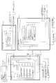
次に、図5を参照して、本パチンコ機10の電気的構成について説明する。図5は、パチンコ機10の電気的構成を示すブロック図である。
<Electrical Configuration in First Embodiment>
Next, the electrical configuration of the
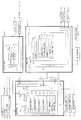
主制御装置110には、演算装置である1チップマイコンとしてのMPU201が搭載されている。MPU201には、該MPU201により実行される各種の制御プログラムや固定値データを記憶したROM202と、そのROM202内に記憶される制御プログラムの実行に際して各種のデータ等を一時的に記憶するためのメモリであるRAM203と、ROM202やRAM203から各種データを読み出したり、RAM203に各種データを書き込んだりする場合に、読み出し、および書き込みに必要なデータを一時的に記憶させるためのレジスタ210と、そのほか、割込回路やタイマ回路、データ送受信回路などの各種回路が内蔵されている。なお、払出制御装置111や音声ランプ制御装置113などのサブ制御装置に対して動作を指示するために、主制御装置110から該サブ制御装置へ各種のコマンドがデータ送受信回路によって送信されるが、かかるコマンドは、主制御装置110からサブ制御装置へ一方向にのみ送信される。
The
次に、図6を参照して、主制御装置110のRAM203について説明する。RAM203には、主制御装置110の処理を制御するための各種カウンタやフラグ、および設定値を格納する記憶領域等が設けられている。ここで、主制御装置110の処理とは、特別図柄の抽選、普通図柄の抽選、第1図柄表示装置37における表示の設定、第2図柄表示装置83における表示の設定、および、第3図柄表示装置81における表示の設定といったパチンコ機10の主要な処理である。
Next, the
図6は、主制御装置110のRAM203内に設けられるカウンタ等を示す図である。これらのカウンタ等は、特別図柄の抽選、普通図柄の抽選、第1図柄表示装置37における表示の設定、第2図柄表示装置83における表示の設定、および、第3図柄表示装置81における表示の設定等を行うために、主制御装置110のMPU201で使用される。
FIG. 6 is a diagram showing a counter and the like provided in the
特別図柄の抽選や、第1図柄表示装置37および第3図柄表示装置81の表示の設定には、特別図柄の抽選に使用する第1当たり乱数カウンタC1と、特別図柄の大当たり種別を選択するために使用する第1当たり種別カウンタC2と、第1当たり乱数カウンタC1の初期値設定に使用する第1初期値乱数カウンタCINI1と、変動パターン選択に使用する変動種別カウンタCS1とが用いられる。また、普通図柄の抽選には、第2当たり乱数カウンタC3が用いられ、第2当たり乱数カウンタC3の初期値設定には第2初期値乱数カウンタCINI2が用いられる。これら各カウンタは、更新の都度、前回値に1が加算され、最大値に達した後0に戻るループカウンタとなっている。
In order to select a special symbol lottery and the first symbol random number counter C1 used for the special symbol lottery and the special symbol lottery for setting the display of the first
各カウンタは、例えば、タイマ割込処理(図24参照)の実行間隔である2ミリ秒間隔で更新され、また、一部のカウンタは、メイン処理(図35参照)の中で不定期に更新されて、その更新値がRAM203の所定領域に設定されたカウンタ用バッファに適宜格納される。RAM203には、1つの実行エリアと4つの保留エリア(保留第1〜第4エリア)とからなる特別図柄保留球格納エリア203aが設けられており、これらの各エリアには、第1入球口64a、または第2入球口64bへの入球タイミングに合わせて、第1当たり乱数カウンタC1、第1当たり種別カウンタC2及び変動種別カウンタCS1の各値がそれぞれ格納される。また、RAM203には、1つの実行エリアと4つの保留エリア(保留第1〜第4エリア)とからなる普通図柄保留球格納エリア203bが設けられており、これらの各エリアには、球が左右何れかの普通入球口(スルーゲート)67を通過したタイミングに合わせて、第2当たり乱数カウンタC3の値が格納される。
Each counter is updated, for example, at an interval of 2 milliseconds, which is the execution interval of the timer interrupt process (see FIG. 24), and some counters are updated irregularly in the main process (see FIG. 35). Then, the updated value is appropriately stored in a counter buffer set in a predetermined area of the
各カウンタについて詳しく説明する。第1当たり乱数カウンタC1は、所定の範囲(例えば、0〜249)内で順に1ずつ加算され、最大値(例えば、0〜249の値を取り得るカウンタの場合は249)に達した後0に戻る構成となっている。特に、第1当たり乱数カウンタC1が1周した場合、その時点の第1初期値乱数カウンタCINI1の値が当該第1当たり乱数カウンタC1の初期値として読み込まれる。 Each counter will be described in detail. The first per-random number counter C1 is incremented by 1 within a predetermined range (for example, 0 to 249) and reaches 0 after reaching the maximum value (for example, 249 for a counter that can take a value of 0 to 249). It is the composition which returns to. In particular, when the first random number counter C1 makes one round, the value of the first initial value random number counter CINI1 at that time is read as the initial value of the first random number counter C1.
また、第1初期値乱数カウンタCINI1は、第1当たり乱数カウンタC1と同一範囲で更新されるループカウンタとして構成される。即ち、例えば、第1当たり乱数カウンタC1が0〜249の値を取り得るループカウンタである場合には、第1初期値乱数カウンタCINI1もまた、0〜249の範囲のループカウンタである。この第1初期値乱数カウンタCINI1は、タイマ割込処理(図24参照)の実行毎に1回更新されると共に、メイン処理(図35参照)の残余時間内で繰り返し更新される。 The first initial value random number counter CINI1 is configured as a loop counter that is updated in the same range as the first random number counter C1. That is, for example, when the first random number counter C1 is a loop counter that can take a value of 0 to 249, the first initial value random number counter CINI1 is also a loop counter in the range of 0 to 249. The first initial value random number counter CINI1 is updated once every execution of the timer interrupt process (see FIG. 24), and is repeatedly updated within the remaining time of the main process (see FIG. 35).
第1当たり乱数カウンタC1の値は、例えば定期的に(本実施形態ではタイマ割込処理毎に1回)更新され、球が第1入球口64a、または第2入球口64bに入賞したタイミングでRAM203の特別図柄保留球格納エリア203aに格納される。そして、特別図柄の大当たりとなる乱数の値は、後述する、主制御装置110のROM202に格納される第1当たり乱数テーブル202a(図7(a)参照)によって設定されており、第1当たり乱数カウンタC1の値が、第1当たり乱数テーブル202aによって設定された大当たりとなる乱数の値と一致する場合に、特別図柄の大当たりと判定する。また、この第1当たり乱数テーブル202aは、特別図柄の低確率時(特別図柄の低確率状態である期間)用と、その低確率時より特別図柄の大当たりとなる確率の高い高確率時(特別図柄の高確率状態である期間)用との2種類に分けられ、それぞれに含まれる大当たりとなる乱数の個数が異なって設定されている。このように、大当たりとなる乱数の個数を異ならせることにより、特別図柄の低確率時と特別図柄の高確率時とで、大当たりとなる確率が変更される。なお、特別図柄の低確率時用の第1当たり乱数テーブル202a1(図示せず)と、特別図柄の高確率時用の第1当たり乱数テーブル202a2(図示せず)とは、主制御装置110のROM202内に設けられている。
The value of the first random number counter C1 is updated, for example, periodically (in this embodiment, once for each timer interrupt process), and the ball has won the
第1当たり種別カウンタC2は、特別図柄の大当たりとなった場合に、第1図柄表示装置37の表示態様を決定するものであり、所定の範囲(例えば、0〜199)内で順に1ずつ加算され、最大値(例えば、0〜199の値を取り得るカウンタの場合は199)に達した後0に戻る構成となっている。第1当たり種別カウンタC2の値は、例えば、定期的に(本実施形態ではタイマ割込処理毎に1回)更新され、球が第1入球口64a、または第2入球口64bに入賞したタイミングでRAM203の特別図柄保留球格納エリア203aに格納される。
The first hit type counter C2 determines the display mode of the first
ここで、特別図柄保留球格納エリア203aに格納された第1当たり乱数カウンタC1の値が、特別図柄の大当たりとなる乱数でなければ、即ち、特別図柄の外れとなる乱数であれば、第1図柄表示装置37に表示される停止図柄に対応した表示態様は、特別図柄の外れ時のものとなる。
Here, if the value of the first per-random number counter C1 stored in the special symbol reserved
一方で、特別図柄保留球格納エリア203aに格納された第1当たり乱数カウンタC1の値が、特別図柄の大当たりとなる乱数であれば、第1図柄表示装置37に表示される停止図柄に対応した表示態様は、特別図柄の大当たり時のものとなる。この場合、その大当たり時の具体的な表示態様は、同じ特別図柄保留球格納エリア203aに格納されている第1当たり種別カウンタC2の値が示す表示態様となる。
On the other hand, if the value of the first per-random number counter C1 stored in the special symbol holding
本実施形態のパチンコ機10における第1当たり乱数カウンタC1は、0〜249の範囲の2バイトのループカウンタとして構成されている。この第1当たり乱数カウンタC1において、特別図柄の低確率時に、特別図柄の大当たりとなる乱数値は3個あり、その乱数値である「7,107,240」は、低確率時用の第1当たり乱数テーブル202aに格納されている。このように特別図柄の低確率時には、乱数値の総数が300ある中で、大当たりとなる乱数値の総数が3なので、特別図柄の大当たりとなる確率は、「1/100」となる。
The first random number counter C1 in the
一方で、特別図柄の高確率時に、特別図柄の大当たりとなる乱数値は30個あり、その値である「4,11,15,28,38,45,52,64,78,83,90,99,106,110,112,122,134,140,151,160,168,176,183,197,207,218,222,231,238,249」は、高確率時用の第1当たり乱数テーブル202aに格納されている。このように特別図柄の高確率時には、乱数値の総数が300ある中で、大当たりとなる乱数値の総数が30なので、特別図柄の大当たりとなる確率は、「1/10」となる。 On the other hand, when there is a high probability of the special symbol, there are 30 random numbers that are jackpots of the special symbol, and the values are “4, 11, 15, 28, 38, 45, 52, 64, 78, 83, 90, 99, 106, 110, 112, 122, 134, 140, 151, 160, 168, 176, 183, 197, 207, 218, 222, 231, 238, 249 ”is a first random number table for high probability. 202a. Thus, when the special symbol has a high probability, the total number of random numbers that are jackpots is 30 among the total number of random number values, so the probability that the special symbol is jackpot is “1/10”.
なお、本実施形態では、低確率時用の第1当たり乱数テーブル202aに格納されている大当たりとなる乱数値と、高確率時用の第1当たり乱数テーブル202aに格納されている大当たりとなる乱数値とで、重複した値とならないように、それぞれの大当たりとなる乱数値を設定している。ここで、大当たりとなる乱数値としてパチンコ機10の状況にかかわらず常に用いられる値が存在すれば、その値が出現するタイミングが解析され、その解析されたタイミングに基づいて不正に大当たりを引き当てられやすくなる虞がある。これに対して、本実施形態のように、状況に応じて(即ち、パチンコ機10が特別図柄の高確率状態か、特別図柄の低確率状態かに応じて)、大当たりとなる乱数値を変えることで、特別図柄の大当たりとなる乱数値が予測され難くすることができるので、不正に対する抑制を図ることができる。
In the present embodiment, the random number that is a big hit stored in the first per-random number table 202a for low probability and the random hit that is stored in the first per-random number table 202a for high probability. Random numbers that are big hits are set so that they do not overlap with numerical values. Here, if there is a value that is always used as a jackpot random value regardless of the situation of the
また、本実施形態のパチンコ機10における第1当たり種別カウンタC2の値は、0〜199の範囲のループカウンタとして構成されている。そして、図7(b)に示すように、この第1当たり種別カウンタC2において、乱数値が「0〜99」であった場合の大当たり種別は、「大当たりA(時短大当たり)」となる。また、値が「100〜179」であった場合の大当たり種別は、「大当たりB(確変大当たり)」となり、値が「180〜194」であった場合の大当たり種別は、「大当たりC(潜伏確変大当たり)」となり、値が「195〜199」であった場合の大当たり種別は、「大当たりD(レア潜伏確変大当たり)」となる。このように、本実施形態のパチンコ機10は、第1当たり種別カウンタC2が示す乱数の値によって、4種類の当たり種別(大当たりA〜大当たりD)のいずれかが決定されるように構成されている。
Further, the value of the first hit type counter C2 in the
変動種別カウンタCS1は、例えば0〜199の範囲内で順に1ずつ加算され、最大値(つまり199)に達した後0に戻る構成となっている。変動種別カウンタCS1によって、例えばリーチの発生しない「完全外れ」や、変動時間が比較的短い「ショートリーチ」、変動時間が比較的長い「ロングリーチ」、変動時間が最長の「スーパーリーチ」等の大まかな表示態様が決定される。表示態様の決定は、具体的には、図柄変動の変動時間の決定である。変動種別カウンタCS1により決定された変動時間に基づいて、音声ランプ制御装置113や表示制御装置114により第3図柄表示装置81で表示される第3図柄のリーチ種別や細かな図柄変動態様が決定される。変動種別カウンタCS1の値は、例えば定期的に(本実施形態ではタイマ割込処理毎に1回)更新され、球が第1入球口64a、または第2入球口64bに入賞したタイミングでRAM203の特別図柄保留球格納エリア203aに格納される。なお、本実施形態のパチンコ機10では、変動種別カウンタCS1の値(乱数値)と、図柄の変動の変動時間を決定するための変動種別データとが対応づけられて変動種別選択テーブル202d(図8(a)参照)に規定されている。この変動種別選択テーブル202d(図8(a)参照)は、主制御装置110のROM202内に設けられている。
For example, the variation type counter CS1 is incremented by 1 within a range of 0 to 199, for example, and reaches a maximum value (that is, 199) and then returns to 0. By the fluctuation type counter CS1, for example, “completely missed” in which reach does not occur, “short reach” in which the fluctuation time is relatively short, “long reach” in which the fluctuation time is relatively long, “super reach” in which the fluctuation time is longest, etc. A rough display mode is determined. Specifically, the display mode is determined by determining the variation time of the symbol variation. Based on the fluctuation time determined by the fluctuation type counter CS1, the voice
詳細については後述するが、変動種別選択テーブル202dには、大当たりに当選した場合に参照されるテーブル(当たり用選択テーブル202d1)と、特別図柄の抽選が外れだった場合に参照されるテーブルとが設けられている。更に、特別図柄の抽選が外れだった場合に参照されるテーブルには2種類存在する。具体的には、球が第1入球口64aに入球し、特別図柄の抽選が外れだった場合に参照されるテーブル(特図1外れ用選択テーブル202d2)と、球が第2入球口64bに入球し、特別図柄の抽選が外れだった場合に参照されるテーブル(特図2外れ用選択テーブル202d3)とが設けられている。また、特図1外れ用選択テーブル202d2から変動種別データを選択する場合に比較して、特図2外れ用選択テーブル202d3から変動種別データを選択する場合は、完全外れに対応する変動種別データが選択される割合が高く設定されている。このように構成することで、第2入球口64bへと入球しやすい状態である特別図柄の確変中、および普通図柄の時短状態中には、特別図柄の抽選に外れた場合に短い変動時間の変動パターン演出を選択されやすくすることができる。外れとなる変動パターン演出の変動時間を短くすることにより、遊技者に対して次の大当たりまでの期間を短く感じさせることができ、大当たりが短い期間で連続するように感じさせることができるので、遊技者の遊技に対する興趣を向上させることができる。
Although details will be described later, in the variation type selection table 202d, there are a table to be referred to when winning the jackpot (a selection table for winning 202d1) and a table to be referred to when the special symbol is not selected. Is provided. Furthermore, there are two types of tables that are referred to when the special symbol lottery is missed. Specifically, a table that is referred to when the ball enters the
第2当たり乱数カウンタC3は、例えば0〜239の範囲内で順に1ずつ加算され、最大値(つまり239)に達した後0に戻るループカウンタとして構成されている。また、第2当たり乱数カウンタC3が1周した場合、その時点の第2初期値乱数カウンタCINI2の値が当該第2当たり乱数カウンタC3の初期値として読み込まれる。第2当たり乱数カウンタC3の値は、本実施形態ではタイマ割込処理毎に、例えば定期的に更新され、球が左右何れかの普通入球口(スルーゲート)67を通過したことが検知された時に取得され、RAM203の普通図柄保留球格納エリア203bに格納される。
For example, the second random number counter C3 is configured as a loop counter that is incremented one by one within a range of 0 to 239 and returns to 0 after reaching the maximum value (that is, 239). When the second random number counter C3 makes one round, the value of the second initial value random number counter CINI2 at that time is read as the initial value of the second random number counter C3. In this embodiment, the value of the second per-random number counter C3 is periodically updated, for example, every timer interrupt process, and it is detected that the ball has passed through the right or left normal entrance (through gate) 67. And is stored in the normal symbol reserved
そして、普通図柄の当たりとなる乱数の値は、主制御装置のROM202に格納される第2当たり乱数テーブル(図7(c)参照)によって設定されており、第2当たり乱数カウンタC3の値が、第2当たり乱数テーブル202cによって設定された当たりとなる乱数の値と一致する場合に、普通図柄の当たりと判定する。また、この第2当たり乱数テーブル202cは、普通図柄の低確率時(普通図柄の通常状態である期間)用と、その低確率時より普通図柄の当たりとなる確率の高い高確率時(普通図柄の時短状態である期間)用との2種類に分けられ、それぞれに含まれる大当たりとなる乱数の個数が異なって設定されている。このように、当たりとなる乱数の個数を異ならせることにより、普通図柄の低確率時と普通図柄の高確率時とで、当たりとなる確率が変更される。
The random number value that is a normal symbol is set by a second random number table (see FIG. 7C) stored in the
図7(c)に示すように、普通図柄の低確率時に、普通図柄の当たりとなる乱数値は24個あり、その範囲は「5〜28」となっている。これら乱数値は、低確率時用の普通図柄当たり乱数テーブルに格納されている。このように普通図柄の低確率時には、乱数値の総数が240ある中で、大当たりとなる乱数値の総数が24なので、特別図柄の大当たりとなる確率は、「1/10」となる。 As shown in FIG. 7 (c), there are 24 random numbers that are hit by the normal symbol when the normal symbol has a low probability, and the range is "5-28". These random values are stored in a random table per normal symbol for low probability. Thus, when the probability of a normal symbol is low, the total number of random numbers that are jackpots is 24 among the total number of random number values, and therefore the probability of jacking a special symbol is “1/10”.
パチンコ機10が普通図柄の低確率時である場合に、球が普通入球口67を通過すると、第2当たり乱数カウンタC3の値が取得されると共に、第2図柄表示装置83において普通図柄の変動表示が30秒間実行される。そして、取得された第2当たり乱数カウンタC3の値が「5〜28」の範囲であれば当選と判定されて、第2図柄表示装置83における変動表示が終了した後に、停止図柄(第2図柄)として「○」の図柄が点灯表示されると共に、第2入球口64bに付随する電動役物が「0.2秒間×1回」だけ開放される。なお、本実施形態では、パチンコ機10が普通図柄の低確率時である場合に、普通図柄の当たりとなったら第2入球口64bに付随する電動役物が「0.2秒間×1回」だけ開放されるが、開放時間や回数は任意に設定すれば良い。例えば、「0.5秒間×2回」開放しても良い。
When the
一方で、普通図柄の高確率時に、普通図柄の大当たりとなる乱数値は200個あり、その範囲は「5〜204」となっている。これらの乱数値は、高確率時用の普通図柄当たり乱数テーブルに格納されている。このように特別図柄の低確率時には、乱数値の総数が240ある中で、大当たりとなる乱数値の総数が200なので、特別図柄の大当たりとなる確率は、「1/1.2」となる。 On the other hand, when there is a high probability of a normal symbol, there are 200 random values that are jackpots of the normal symbol, and the range is “5-204”. These random number values are stored in a random table per symbol for high probability. Thus, when the special symbol has a low probability, the total number of random numbers that are jackpots is 200 among the total number of random number values, and therefore, the probability that the special symbol is jackpot is “1 / 1.2”.
パチンコ機10が普通図柄の高確率時である場合に、球が普通入球口67を通過すると、第2当たり乱数カウンタC3の値が取得されると共に、第2図柄表示装置83において普通図柄の変動表示が3秒間実行される。そして、取得された第2当たり乱数カウンタC3の値が「5〜204」の範囲であれば当選と判定されて、第2図柄表示装置83における変動表示が終了した後に、停止図柄(第2図柄)として「○」の図柄が点灯表示されると共に、第2入球口64bに付随する電動役物が「1秒間×2回」開放される。このように、普通図柄の高確率時には、普通図柄の低確率時と比較して、変動表示の時間が「30秒→3秒」と非常に短くなり、更に、第2入球口64bに付随する電動役物の開放期間が「0.2秒×1回→1秒間×2回」と非常に長くなるので、第2入球口64bへ球が入球し易い状態となる。この、第2当たり乱数カウンタC3の値(乱数値)から、普通図柄の当たりか否かを判定する乱数値を格納した第2当たり乱数テーブル202c(図7(c)参照)は、ROM202内に設けられている。なお、本実施形態では、パチンコ機10が普通図柄の高確率時である場合に、普通図柄の当たりとなったら、第2入球口64bに付随する電動役物が「1秒間×2回」だけ開放されるが、開放時間や回数は任意に設定すれば良い。例えば、「3秒間×3回」開放しても良い。
When the
第2初期値乱数カウンタCINI2は、第2当たり乱数カウンタC3と同一範囲で更新されるループカウンタとして構成され(値=0〜239)、タイマ割込処理(図24参照)毎に1回更新されると共に、メイン処理(図35参照)の残余時間内で繰り返し更新される。 The second initial value random number counter CINI2 is configured as a loop counter that is updated within the same range as the second random number counter C3 (value = 0 to 239), and is updated once every timer interrupt process (see FIG. 24). And repeatedly updated within the remaining time of the main process (see FIG. 35).
このように、RAM203には種々のカウンタ等が設けられており、主制御装置110では、このカウンタ等の値に応じて大当たり抽選や第1図柄表示装置37および第3図柄表示装置81における表示の設定、第2図柄表示装置83における表示結果の抽選といったパチンコ機10の主要な処理を実行することができる。
As described above, the
図5に戻り、説明を続ける。RAM203は、図9に図示した各種カウンタのほか、MPU201のレジスタ210の内容やMPU201により実行される制御プログラムの戻り先番地などが記憶されるスタックエリアと、各種のフラグおよびカウンタ、I/O等の値が記憶される作業エリア(作業領域)とを有している。
Returning to FIG. 5, the description will be continued. In addition to the various counters illustrated in FIG. 9, the
なお、RAM203は、パチンコ機10の電源の遮断後においても電源装置115からバックアップ電圧が供給されてデータを保持(バックアップ)できる構成となっており、RAM203に記憶されるデータは、すべてバックアップされる。
Note that the
停電などの発生により電源が遮断されると、その電源遮断時(停電発生時を含む。以下同様)のスタックポインタや、レジスタ210の各レジスタの値がRAM203に記憶される。一方、電源投入時(停電解消による電源投入を含む。以下同様)には、RAM203に記憶される情報に基づいて、パチンコ機10の状態が電源遮断前の状態に復帰される。RAM203への書き込みはメイン処理(図35参照)によって電源遮断時に実行され、RAM203に書き込まれた各値の復帰は電源投入時の立ち上げ処理(図34参照)において実行される。なお、MPU201のNMI端子(ノンマスカブル割込端子)には、停電等の発生による電源遮断時に、停電監視回路252からの停電信号SG1が入力されるように構成されており、その停電信号SG1がMPU201へ入力されると、停電時処理としてのNMI割込処理(図33参照)が即座に実行される。
When the power is shut down due to the occurrence of a power failure or the like, the stack pointer at the time of power shutdown (including the time of power failure, the same applies hereinafter) and the values of the registers in the
また、RAM203は、図5に示すように、特別図柄保留球格納エリア203aと、普通図柄保留球格納エリア203bと、特別図柄保留球数カウンタ203cと、普通図柄保留球数カウンタ203dと、各種設定値格納エリア203eとを有している。
Further, as shown in FIG. 5, the
特別図柄保留球格納エリア203aは、1つの実行エリアと、4つの保留エリア(保留第1エリア〜保留第4エリア)とを有しており、これらの各エリアには、第1当たり乱数カウンタC1、第1当たり種別カウンタC2、及び変動種別カウンタCS1の各値がそれぞれ格納される。
The special symbol holding
より具体的には、球が第1入球口64a、または第2入球口64bへ入賞(始動入賞)したタイミングで、各カウンタC1,C2,CS1の各値が取得され、その取得されたデータが、4つの保留エリア(保留第1エリア〜保留第4エリア)の空いているエリアの中で、エリア番号(第1〜第4)の小さいエリアから順番に記憶される。つまり、エリア番号の小さいエリアほど、時間的に古い入賞に対応するデータが記憶され、保留第1エリアには、時間的に最も古い入賞に対応するデータが記憶される。なお、4つの保留エリアの全てにデータが記憶されている場合には、新たに何も記憶されない。
More specifically, each value of each of the counters C1, C2, and CS1 is acquired at the timing when the ball wins (start winning) at the
その後、主制御装置110において、特別図柄の抽選が行われる場合には、特別図柄保留球格納エリア203aの保留第1エリアに記憶されている各カウンタC1,C2,CS1の各値が、実行エリアへシフトされ(移動させられ)、その実行エリアに記憶された各カウンタC1,C2,CS1の各値に基づいて、特別図柄の抽選などの判定が行われる。
Thereafter, when the special controller lottery is performed in the
なお、保留第1エリアから実行エリアへデータをシフトすると、保留第1エリアが空き状態となる。そこで、他の保留エリア(保留第2エリア〜保留第4エリア)に記憶されている入賞のデータを、エリア番号の1小さい保留エリア(保留第1エリア〜保留第3エリア)に詰めるシフト処理が行われる。本実施形態では、特別図柄保留球格納エリア203aにおいて、入賞のデータが記憶されている保留エリア(第2保留エリア〜第4保留エリア)についてのみデータのシフトが行われる。
Note that when data is shifted from the reserved first area to the execution area, the reserved first area becomes empty. Therefore, a shift process is performed in which winning data stored in other reserved areas (holding second area to holding fourth area) is packed into a holding area having a smaller area number (holding first area to holding third area). Done. In the present embodiment, in the special symbol reserved
本パチンコ機10では、球が第1入球口64a、または第2入球口64bへ入賞(始動入賞)し、その始動入賞に応じて各カウンタC1,C2,CS1の各値が取得されると直ちに、本来の特別図柄の大当たり抽選とは別に、その取得された各カウンタC1,C2,CS1の各値から、本来の抽選が行われた場合に得られる各種情報が予測(推定)される。このように、本来の特別図柄の抽選が行われる前に、始動入賞に対応するデータ(各カウンタC1,C2,CS1の各値)に基づいて、本来の抽選が行われた場合に得られる各種情報を予測することを、以後、特別図柄の抽選結果を先読みすると記載する。なお、各種情報としては、当否、停止種別、変動パターンなどが該当する。
In the
そして、先読みが終了すると、先読みにより得られた各種情報(当否、停止種別、変動パターン)を含む入賞情報コマンドが音声ランプ制御装置113へ送信される。入賞情報コマンドが音声ランプ制御装置113によって受信されると、音声ランプ制御装置113は、入賞情報コマンドから、当否、停止種別、および変動パターンを抽出し、それらを入賞情報としてRAM223の入賞情報格納エリア223aに格納する。
When the prefetching is completed, a winning information command including various types of information (presence / absence, stop type, variation pattern) obtained by the prefetching is transmitted to the sound
普通図柄保留球格納エリア203bは、特別図柄保留球格納エリア203aと同様に、1つの実行エリアと、4つの保留エリア(保留第1エリア〜保留第4エリア)とを有している。これらの各エリアには、第2当たり乱数カウンタC3が格納される。
Similarly to the special symbol reserved
より具体的には、球が左右何れかの普通入球口67を通過したタイミングで、第2当たり乱数カウンタC3の値が取得され、その取得されたデータが、4つの保留エリア(保留第1エリア〜保留第4エリア)の空いているエリアの中で、エリア番号(第1〜第4)の小さいエリアから順番に記憶される。つまり、特別図柄保留球格納エリア203aと同様に、入賞した順序が保持されつつ、入賞に対応するデータが格納される。なお、4つの保留エリアの全てにデータが記憶されている場合には、新たに何も記憶されない。
More specifically, the value of the second per-random number counter C3 is acquired at the timing when the ball passes the left or right
その後、主制御装置110において、普通図柄の当たりの抽選が行われる場合には、普通図柄保留球格納エリア203bの保留第1エリアに記憶されている第2当たり乱数カウンタC3の値が、実行エリアへシフトされ(移動させられ)、その実行エリアに記憶された第2当たり乱数カウンタC3の値に基づいて、普通図柄の当たりの抽選などの判定が行われる。
Thereafter, when the
なお、保留第1エリアから実行エリアへデータをシフトすると、保留第1エリアが空き状態となるので、特別図柄保留球格納エリア203aの場合と同様に、他の保留エリアに記憶されている入賞のデータを、エリア番号の1小さい保留エリアに詰めるシフト処理が行われる。また、データのシフトも、入賞のデータが記憶されている保留エリアについてのみ行われる。
Note that when the data is shifted from the reserved first area to the execution area, the reserved first area becomes empty. Therefore, as in the case of the special symbol reserved
特別図柄保留球数カウンタ203cは、第1入球口64a、または第2入球口64bへの入球(始動入賞)に基づいて第1図柄表示装置37で行われる特別図柄(第1図柄)の変動表示(第3図柄表示装置81で行われる変動表示)の保留球数(待機回数)を最大4回まで計数するカウンタである。この特別図柄保留球数カウンタ203cは、初期値がゼロに設定されており、第1入球口64a、または第2入球口64bへ球が入球して変動表示の保留球数が増加する毎に、最大値4まで1加算される(図30のS704参照)。一方、特別図柄保留球数カウンタ203cは、新たに特別図柄の変動表示が実行される毎に、1減算される(図25のS205参照)。
The special symbol reservation
この特別図柄保留球数カウンタ203cの値(特別図柄における変動表示の保留回数N)は、保留球数コマンドによって音声ランプ制御装置113に通知される(図25のS206、図30のS705参照)。保留球数コマンドは、特別図柄保留球数カウンタ203cの値が変更される度に、主制御装置110から音声ランプ制御装置113に対して送信されるコマンドである。
The value of the special symbol reserved
音声ランプ制御装置113は、特別図柄保留球数カウンタ203cの値が変更される度に、主制御装置110より送信される保留球数コマンドによって、主制御装置110に保留された変動表示の保留球数そのものの値を取得することができる。これにより、音声ランプ制御装置113の特別図柄保留球数カウンタ223bによって管理される変動表示の保留球数が、ノイズ等の影響によって、主制御装置110に保留された実際の変動表示の保留球数からずれてしまった場合であっても、次に受信する保留球数コマンドによって、そのずれを修正することができる。
The voice
なお、音声ランプ制御装置113は、保留球数コマンドに基づいて保留球数を管理し、保留球数が変化する度に表示制御装置114に対して、保留球数を通知するための表示用保留球数コマンドを送信する。表示制御装置114は、この表示用保留球数コマンドによって通知された保留球数を基に、第3図柄表示装置81の小領域Ds1に保留球数図柄を表示する。
The voice
普通図柄保留球数カウンタ203dは、普通入球口67における球の通過に基づいて第2図柄表示装置83で行われる普通図柄(第2図柄)の変動表示の保留球数(待機回数)を最大4回まで計数するカウンタである。この普通図柄保留球数カウンタ203dは、初期値がゼロに設定されており、球が普通入球口67を通過して変動表示の保留球数が増加する毎に、最大値4まで1加算される(図32のS904参照)。一方、普通図柄保留球数カウンタ203dは、新たに普通図柄(第2図柄)の変動表示が実行される毎に、1減算される(図31のS805参照)。
The normal symbol reserved
球が左右何れかの普通入球口67を通過した場合に、この普通図柄保留球数カウンタ203dの値(普通図柄における変動表示の保留回数M)が4未満であれば、第2当たり乱数カウンタC3の値が取得され、その取得されたデータが、普通図柄保留球格納エリア203bに記憶される(図32のS905)。一方、球が左右何れかの普通入球口67を通過した場合に、この普通図柄保留球数カウンタ203dの値が4であれば、普通図柄保留球格納エリア203bには新たに何も記憶されない(図32のS903:No)。
If the value of the normal symbol reserved
各種設定値格納エリア203eは、パチンコ機10の主要な処理を実行するための様々な設定値やフラグ、カウンタ等が格納されている記憶領域である。MPU201は、各種設定値格納エリア203eに格納されたデータに基づいて制御を行う。この各種設定値格納エリア203eについては、図15を参照して後述する。
The various set
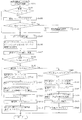
図5に戻って説明を続ける。ROM202には、MPU201により実行される各種の制御プログラムや固定値データが規定されている。このROM202の内容について、図7〜図14を参照して説明する。図7(a)に示すように、主制御装置110のROM202には、上記した固定値データの一部として、第1当たり乱数テーブル202a、第1当たり種別選択テーブル202b、第2当たり乱数テーブル202c、変動種別選択テーブル202d、オフセット設定テーブル202e、変動パターン選択テーブル202f、遊技結果設定テーブル202g、状態設定テーブル202h、大当たり終了時クリアテーブル202iが少なくとも記憶されている。
Returning to FIG. Various control programs executed by the
上述した通り、第1当たり乱数テーブル202a(図示せず)は、第1当たり乱数カウンタC1の大当たり判定値が記憶されているデータテーブルである。この第1当たり乱数テーブル202aに規定されたいずれかの乱数値と、第1当たり乱数カウンタバッファに格納された第1当たり乱数カウンタC1の値とが一致した場合に、特別図柄の大当たりと判別される。 As described above, the first hit random number table 202a (not shown) is a data table in which the jackpot determination value of the first hit random number counter C1 is stored. When any one of the random number values defined in the first random number table 202a matches the value of the first random number counter C1 stored in the first random number counter buffer, it is determined that the special symbol is a big hit. The
第1当たり種別選択テーブル202b(図7(b)参照)は、大当たり種別を決定するための第1当たり種別カウンタC2の判定値が、大当たり種別毎にそれぞれ設定されているデータテーブルである。図7(b)に示した通り、第1当たり種別カウンタバッファに格納された第1当たり種別カウンタC2の値が0〜99の範囲であれば、今回の大当たりは「大当たりA(時短大当たり)」と判定され、第1当たり種別カウンタC2の値が100〜179の範囲であれば、今回の大当たりは「大当たりB(確変大当たり)」と判定される。また、第1当たり種別カウンタC2の値が180〜194範囲であれば、今回の大当たりは「大当たりC(潜伏確変大当たり)」と判定され、第1当たり種別カウンタC2の値が195〜199の範囲であれば、今回の大当たりは「大当たりD(レア潜伏確変大当たり)」と判定される。 The first hit type selection table 202b (see FIG. 7B) is a data table in which determination values of the first hit type counter C2 for determining the big hit type are set for each big hit type. As shown in FIG. 7B, if the value of the first hit type counter C2 stored in the first hit type counter buffer is in the range of 0 to 99, the big hit this time is “big hit A (short-term big hit)”. If the value of the first hit type counter C2 is in the range of 100 to 179, the current big hit is determined as “big hit B (probability big hit)”. Also, if the value of the first hit type counter C2 is in the range of 180 to 194, the current big hit is determined as “big hit C (latency probability variation big hit)”, and the value of the first hit type counter C2 is in the range of 195 to 199. If this is the case, the current jackpot is determined to be a jackpot D (rare latency probability change jackpot).
大当たり終了後に特別図柄の低確率状態へと移行すると共に、普通図柄の時短状態へと移行する大当たりとなる乱数値は、0〜99の100個に設定されている。一方、大当たり終了後に特別図柄の高確率状態へと移行する大当たり(大当たりB〜大当たりD)となる乱数値は、100〜199の100個に設定されている。つまり、大当たり終了後に特別図柄の高確率状態へと移行する大当たりと、特別図柄の低確率状態へと移行する大当たりとの比率は1:1である。また、特別図柄の高確率状態へと移行する大当たりのうち、特別図柄の高確率状態へと移行することが遊技者に報知されない大当たり(大当たりC、大当たりD)となる乱数値は、180〜199の20個に設定されている。即ち、特別図柄の高確率状態へと移行する大当たりに当選する場合の5回に1回は、特別図柄の高確率状態へと移行することが報知されないように構成されている。これにより、特別図柄の高確率状態へと移行することが報知されなかったとしても、遊技者に対して特別図柄の高確率状態へと移行していること(即ち、大当たりC、または大当たりDに当選したこと)を期待させながら遊技を続けさせることができる。 The number of random numbers that are jackpots that shift to the low probability state of the special symbol after the jackpot ends and that shift to the short-time state of the normal symbol are set to 100 from 0 to 99. On the other hand, 100 random numbers of 100 to 199 are set as the jackpots (jackpot B to jackpot D) that shift to the high probability state of the special symbol after the jackpot ends. That is, the ratio of the jackpot that shifts to the high probability state of the special symbol after the end of the jackpot and the jackpot that shifts to the low probability state of the special symbol is 1: 1. In addition, among the jackpots that shift to the high probability state of the special symbol, random numbers that become jackpots (jackpot C, jackpot D) that are not notified to the player that the transition to the special symbol high probability state is 180 to 199. 20 are set. That is, it is configured not to notify the transition to the high probability state of the special symbol once every five times when winning the jackpot to shift to the high probability state of the special symbol. Thereby, even if it is not informed that the transition to the high probability state of the special symbol is made, the player has transitioned to the high probability state of the special symbol (that is, the jackpot C or the jackpot D) The game can be continued with the expectation of winning.
第2当たり乱数テーブル202c(図7(c)参照)は、普通図柄の当たり判定値が記憶されているデータテーブルである。図7(c)に示した通り、普通図柄の低確率時(普通図柄の通常状態中)は、第2当たり乱数カウンタバッファに格納された第2当たり乱数カウンタC3の値が5〜28の範囲の場合に普通図柄の当たりと判定される。なお、上述の通り、普通図柄の当たりと判定された場合は、第2図柄表示装置83における変動表示が終了した後に、停止図柄(第2図柄)として「○」の図柄が点灯表示されると共に、第2入球口64bに付随する電動役物が「0.2秒間×1回」だけ開放される。
The second hit random number table 202c (see FIG. 7C) is a data table in which the hit determination value for the normal symbol is stored. As shown in FIG. 7C, when the normal symbol has a low probability (in the normal state of the normal symbol), the value of the second random number counter C3 stored in the second random number counter buffer is in the range of 5 to 28. In the case of, it is determined that the symbol is a normal symbol. As described above, when it is determined that the symbol is a normal symbol, after the variable display on the second
一方、普通図柄の高確率時(普通図柄の時短状態中)は、第2当たり乱数カウンタC3の値が5〜204の範囲の場合に普通図柄の当たりと判定される。なお、上述の通り、普通図柄の当たりと判定された場合は、第2図柄表示装置83における変動表示が終了した後に、停止図柄(第2図柄)として「○」の図柄が点灯表示されると共に、第2入球口64bに付随する電動役物が「1秒間×2回」開放される。
On the other hand, when the normal symbol has a high probability (during the normal symbol time short state), it is determined that the normal symbol is hit when the value of the second random number counter C3 is in the range of 5 to 204. As described above, when it is determined that the symbol is a normal symbol, after the variable display on the second
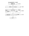
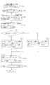
変動種別選択テーブル202d(図8(a)参照)は、変動パターンの大まかな表示態様を決定するための変動種別データと、変動種別カウンタCS1との対応関係が規定されているデータテーブルである。この変動種別選択テーブル202dには、特別図柄の抽選結果や球が入球した入球口の種別に対応した複数の異なるテーブルが規定されている。この変動種別選択テーブル202d(図8(a)参照)から選択した変動種別データを、後述するオフセット設定テーブル202e(図10参照)に基づいてオフセット値(パターン選択オフセット値)に変換する。そして、変動パターン選択テーブル202f(図11参照)の先頭アドレスからオフセット値分だけ先のアドレスに規定されている内容を変動パターン種別として設定する。 The variation type selection table 202d (see FIG. 8A) is a data table in which the correspondence between the variation type data for determining the rough display mode of the variation pattern and the variation type counter CS1 is defined. The variation type selection table 202d defines a plurality of different tables corresponding to the lottery results of special symbols and the types of entrances into which balls have entered. The variation type data selected from the variation type selection table 202d (see FIG. 8A) is converted into an offset value (pattern selection offset value) based on an offset setting table 202e (see FIG. 10) described later. Then, the contents defined in the address ahead of the offset value from the start address of the variation pattern selection table 202f (see FIG. 11) are set as the variation pattern type.
図8(a)に示した通り、変動種別選択テーブル202dは、当たり用選択テーブル202d1と、特図1外れ用選択テーブル202d2と、特図2外れ用選択テーブル202d3とを有して構成されている。当たり用選択テーブル202d1は、特別図柄の抽選結果が大当たりであった場合に変動種別データを選択するためのテーブルである。また、特図1外れ用選択テーブル202d2は、球が第1入球口64aへと入球したことに基づいて行われた特別図柄の抽選(特別図柄1の抽選)が外れであった場合に変動種別データを選択するためのテーブルであり、特図2外れ用選択テーブル202d3は、球が第2入球口64bへと入球したことに基づいて行われた特別図柄の抽選(特別図柄2の抽選)が外れであった場合に変動種別データを選択するためのテーブルである。
As shown in FIG. 8A, the variation type selection table 202d includes a hit selection table 202d1, a special figure 1 off selection table 202d2, and a special figure 2 off selection table 202d3. Yes. The winning selection table 202d1 is a table for selecting variation type data when the special symbol lottery result is a big hit. In addition, the special figure 1 removal selection table 202d2 is used when the special symbol lottery (the
次いで、図8(b)〜図11を参照して、変動パターン選択テーブル202f(図11参照)から変動パターン種別を選択するまでの流れについて具体的に説明する。 Next, with reference to FIG. 8B to FIG. 11, a flow until the variation pattern type is selected from the variation pattern selection table 202f (see FIG. 11) will be specifically described.
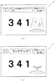
図8(b)は、特別図柄の大当たりと判別された場合に、変動種別カウンタCS1の値に基づいて変動種別データを選択するための当たり用選択テーブル202d1を示した図である。図8(b)に示す通り、特別図柄の大当たりの場合に選択され得る変動パターンの態様は、「当たりショートリーチ」、「当たりロングリーチ」、「当たりスーパーリーチ」の3種類であり、これらに対して変動種別データ00H,01H,02Hがそれぞれ対応付けられている。そして、変動種別カウンタCS1の値が0〜4の範囲であれば変動種別データとして00H(当たりショートリーチ)が選択され、5〜179の範囲であれば変動種別データとして01H(当たりロングリーチ)が選択され、180〜199の範囲であれば変動種別データとして02H(当たりスーパーリーチ)が選択される。これらの変動種別データは、後述するオフセット設定テーブル202eにより、変動パターン種別を選択するために用いる値であるパターン選択オフセット値に変換され、その変動パターン選択オフセット値に基づいて後述する変動パターン選択テーブル202fから変動パターン種別が選択される。
FIG. 8B is a diagram showing a hit selection table 202d1 for selecting the variation type data based on the value of the variation type counter CS1 when it is determined that the special symbol is a big hit. As shown in FIG. 8 (b), there are three types of variation patterns that can be selected in the case of special symbol jackpots: “Short Short Reach”, “Short Long Reach”, and “Short Super Reach”. On the other hand,
図9(a)は、球が第1入球口64aへと入球したことに基づいて行われた特別図柄の抽選(特別図柄1の抽選)が外れであった場合に、変動種別データを選択するための特図1外れ用選択テーブル202d2を示した図である。図9(a)に示す通り、特別図柄1の抽選が外れであった場合に選択され得る変動パターンの態様は、「完全外れ」、「外れショートリーチ」、「外れロングリーチ」、「外れスーパーリーチ」の4種類であり、これらに対して変動種別データ03H,04H,05H,06Hがそれぞれ対応付けられている。
FIG. 9A shows the variation type data when the special symbol lottery (the lottery of the special symbol 1) performed based on the ball entering the
変動種別カウンタCS1の値が0〜164の範囲であれば変動種別データとして03H(完全外れ)が選択され、165〜184の範囲であれば変動種別データとして04H(外れショートリーチ)が選択され、185〜194の範囲であれば変動種別データとして05Hが選択され、195〜199の範囲であれば変動種別データとして06Hが選択される。これらの変動種別データも、大当たりの場合と同様に、オフセット設定テーブル202eを用いてパターン選択オフセット値に変換され、変動パターン選択テーブル202fから変動パターン種別を選択するために用いられる。 If the value of the variation type counter CS1 is in the range of 0 to 164, 03H (completely out) is selected as the variation type data, and if it is in the range of 165 to 184, 04H (out of short reach) is selected as the variation type data. If it is in the range of 185 to 194, 05H is selected as the variation type data, and if it is in the range of 195 to 199, 06H is selected as the variation type data. These variation type data are also converted into pattern selection offset values using the offset setting table 202e and used to select a variation pattern type from the variation pattern selection table 202f, as in the case of jackpot.
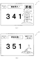
図9(b)は、球が第2入球口64bへと入球したことに基づいて行われた特別図柄の抽選(特別図柄2の抽選)が外れであった場合に、変動種別データを選択するための特図2外れ用選択テーブル202d3を示した図である。図9(b)に示す通り、特別図柄2の抽選が外れであった場合に選択され得る変動パターンの態様は、「完全外れ」、「外れショートリーチ」、「外れロングリーチ」、「外れスーパーリーチ」の4種類であり、これらに対して変動種別データ07H,08H,09H,0AHがそれぞれ対応付けられている。
FIG. 9B shows the variation type data when the special symbol lottery (the lottery of the special symbol 2) performed based on the ball entering the
変動種別カウンタCS1の値が0〜184の範囲であれば変動種別データとして07H(完全外れ)が選択される。即ち、球が第1入球口64aへと入球した場合に比べ、完全外れが選択される割合が高くなるように設定されている。また、185〜194の範囲であれば変動種別データとして08H(外れショートリーチ)が選択され、195〜198の範囲であれば変動種別データとして09Hが選択され、変動種別カウンタCS1の値が199であれば変動種別データとして0AHが選択される。即ち、球が第1入球口64aへ入球した場合に比べ、外れショートリーチ、外れロングリーチ、外れスーパーリーチが選択される割合がそれぞれ低く設定されている。完全外れの割合を高め、各種外れリーチの割合を低くすることにより、特別図柄の高確率状態や、普通図柄の時短状態において変動時間が短い変動パターン演出が選択されやすくなるので、次の大当たりまでの期間を短くすることができ、遊技者に対して大当たりが短期間に連続しているという印象を与えることができる。よって、遊技者の遊技に対する興趣を向上させることができる。なお、特図2外れ用選択テーブル202d3から選択された変動種別データも、大当たりの場合や、球が第1入球口64aに入球した場合と同様に、オフセット設定テーブル202eを用いてパターン選択オフセット値に変換され、変動パターン選択テーブル202fから変動パターン種別を選択するために用いられる。
If the value of the variation type counter CS1 is in the range of 0 to 184, 07H (completely out) is selected as the variation type data. That is, it is set so that the rate at which complete detachment is selected is higher than when the ball enters the
図10は、変動パターン選択テーブル202fから変動パターン種別を選択するためのパターン選択オフセット値を決定するために参照されるオフセット設定テーブル202eを示す図である。 FIG. 10 is a diagram showing an offset setting table 202e that is referred to in order to determine a pattern selection offset value for selecting a variation pattern type from the variation pattern selection table 202f.
図10に示す通り、変動種別選択テーブル202dから選択した変動種別データ値が00H,01H,02Hの場合、オフセット設定テーブル202e(図10参照)から、パターン選択オフセット値として00H,01H,02Hがそれぞれ選択される。一方、選択した変動種別データ値が03H(第1入球口64aでの完全外れ)であった場合、保留球の数に応じて選択されるパターン選択オフセット値が変わるように構成されている。具体的には、保留球数が0の場合には、パターン選択オフセット値として03Hが選択され、保留球数が1の場合は、パターン選択オフセット値として04Hが選択される。また、保留球数が2の場合は、パターン選択オフセット値として05Hが選択され、保留球数が3の場合は、パターン選択オフセット値として06Hが選択される。保留球数に応じて、選択されるパターン選択オフセット値を変更することで、選択される変動パターン種別を保留球数に応じて変更することができる。詳細については後述するが、本実施形態では、保留球数が多いほど、変動期間の短い変動パターン種別が選択されるように構成されている。これにより、変動期間の長い外れの変動パターンばかりが連続してしまうことを抑制することができるので、遊技者の遊技に対するモチベーションを削いでしまうことを抑制することができる。
As shown in FIG. 10, when the variation type data values selected from the variation type selection table 202d are 00H, 01H, and 02H, 00H, 01H, and 02H are respectively selected as the pattern selection offset values from the offset setting table 202e (see FIG. 10). Selected. On the other hand, when the selected variation type data value is 03H (complete deviation from the
なお、変動種別カウンタCS1の値に基づいて変動パターン種別を特定する処理は、保留第1エリアから実行エリアへデータがシフトされた場合に行われる。この場合、他の保留エリアに記憶されている入賞データは、シフト処理によりエリア番号の1小さい保留エリア(保留第1エリア〜保留第3エリア)に詰められているので、パターン選択オフセット値を選択するタイミングにおいて、保留されている入賞データ(保留球数)の最大値は3である。このため、オフセット値設定テーブル202eは、保留球数0〜3の場合について規定している。 The process of specifying the variation pattern type based on the value of the variation type counter CS1 is performed when data is shifted from the reserved first area to the execution area. In this case, the winning data stored in the other reserved areas are packed into the reserved areas with the smaller area numbers (the reserved first area to the reserved third area) by the shift process, so the pattern selection offset value is selected. The maximum value of the winning data (the number of balls to be held) that is held at the timing of holding is 3. For this reason, the offset value setting table 202e defines the case where the number of reserved balls is 0 to 3.
変動種別選択テーブル202dから選択した変動種別データ値が04H(第1入球口64aでの外れショートリーチ)の場合、オフセット設定テーブル202e(図10参照)から、パターン選択オフセット値として07Hが選択される。一方、選択した変動種別データ値が05H(第1入球口64aでの外れロングリーチ)であった場合は、完全外れの場合と同様に、保留球の数に応じて選択されるパターン選択オフセット値が変わる。具体的には、保留球数が0の場合には、パターン選択オフセット値として08Hが選択され、保留球数が1の場合は、パターン選択オフセット値として09Hが選択される。保留球数が2の場合は、パターン選択オフセット値として0AHが選択され、保留球数が3の場合は、パターン選択オフセット値として0BHが選択される。これにより、完全外れの場合と同様に、変動期間の長い外れの変動パターンばかりが連続してしまうことを抑制することができるので、遊技者の遊技に対するモチベーションを削いでしまうことを抑制することができる。
When the variation type data value selected from the variation type selection table 202d is 04H (displacement short reach at the
変動種別選択テーブル202dから選択した変動種別データ値が06H(第1入球口64aでの外れスーパーリーチ)の場合、オフセット設定テーブル202e(図10参照)から、パターン選択オフセット値として0CHが選択される。一方、選択した変動種別データ値が07H(第2入球口64bでの完全外れ)であった場合は、保留球の数に応じて選択されるパターン選択オフセット値が変わる。具体的には、保留球数が0の場合には、パターン選択オフセット値として0DHが選択され、保留球数が1の場合は、パターン選択オフセット値として0EHが選択される。保留球数が2の場合は、パターン選択オフセット値として0FHが選択され、保留球数が3の場合は、パターン選択オフセット値として10Hが選択される。これにより、変動期間の長い外れの変動パターンばかりが連続してしまうことを抑制することができるので、遊技者の遊技に対するモチベーションを削いでしまうことを抑制することができる。
When the variation type data value selected from the variation type selection table 202d is 06H (displacement super reach at the
変動種別選択テーブル202dから選択した変動種別データ値が08H,09H,0AHの場合、オフセット設定テーブル202e(図10参照)から、パターン選択オフセット値として11H,12H,13Hがそれぞれ選択される。上述の通り、オフセット設定テーブル202e(図10参照)から選択されたパターン選択オフセット値は、変動パターン選択テーブル202fから変動パターン種別を選択するために用いられる。 When the variation type data values selected from the variation type selection table 202d are 08H, 09H, and 0AH, 11H, 12H, and 13H are selected as pattern selection offset values from the offset setting table 202e (see FIG. 10), respectively. As described above, the pattern selection offset value selected from the offset setting table 202e (see FIG. 10) is used to select the variation pattern type from the variation pattern selection table 202f.
図11は、パターン選択オフセット値に基づいて変動パターン種別を選択するための変動パターン選択テーブル202fを示した図である。変動パターン選択テーブル202fは、ROM202のアドレス1AF5H〜1B08Hの範囲に割り当てられたデータテーブルであり、各アドレスに、変動パターン種別が1種類ずつ規定されている。具体的には、図11に示すように、変動時間が30秒の「当たりスーパーリーチ」や、変動時間が8秒の「完全外れB(特図1)」、変動時間が19秒の「外れロングリーチB(特図1)」や、変動時間が4秒の「完全外れD(特図2)」等が規定されている。なお、特図1は、球が第1入球口64aへ入球したことに基づく変動を示し、特図2は、球が第2入球口64bへ入球したことに基づく変動を示す。
FIG. 11 is a diagram showing a variation pattern selection table 202f for selecting a variation pattern type based on the pattern selection offset value. The variation pattern selection table 202f is a data table assigned to the range of addresses 1AF5H to 1B08H of the
本実施形態のパチンコ機10では、この変動パターン選択テーブル202fと、パターン選択オフセット値とに基づいて、変動を実行する際の変動パターン種別を決定する。具体的には、変動パターン選択テーブル202fの先頭アドレスである1AF5Hに対して、選択したパターン選択オフセット値の分だけ先のアドレスに規定されている変動パターン種別を、今回の変動パターン種別として決定するように構成されている。
In the
例えば、特別図柄の大当たりとなり、変動種別カウンタCS1の値が100の場合は、当たり用選択テーブル202d1(図8(b)参照)から変動種別データとして01Hが選択される。その変動種別データ値と、オフセット設定テーブル202e(図10参照)とに基づいて、パターン選択オフセット値として01Hが選択される。よって、今回の変動パターン種別として、変動パターン選択テーブル202fの先頭アドレスである1AF5Hに、パターン選択オフセット値の01Hを加えたアドレスである1AF6Hに規定されているデータが選択される。即ち、変動期間が20秒の「当たりロングリーチ」が選択される。 For example, if the special symbol is a big hit and the value of the variation type counter CS1 is 100, 01H is selected as variation type data from the winning selection table 202d1 (see FIG. 8B). Based on the variation type data value and the offset setting table 202e (see FIG. 10), 01H is selected as the pattern selection offset value. Therefore, as the current variation pattern type, data defined in 1AF6H, which is an address obtained by adding 01H of the pattern selection offset value to 1AF5H, which is the first address of the variation pattern selection table 202f, is selected. That is, the “long hit reach” with a variation period of 20 seconds is selected.
また、例えば、球が第1入球口64aへと入球したことに基づく特別図柄の抽選結果が外れであり、変動種別カウンタの値が190であり、且つ、保留球数が2である場合は、特図1外れ用選択テーブル202d2(図9(a)参照)から変動種別データとして05Hが選択される。そして、変動種別データと、保留球数と、オフセット設定テーブル202e(図10参照)とに基づき、パターン選択オフセット値として0AHが選択される。よって、今回の変動パターン種別として、変動パターン選択テーブル202fの先頭アドレスである1AF5に、パターン選択オフセット値の0AHを加えたアドレスである1AFFHに規定されているデータが選択される。即ち、変動時間が17秒の「外れロングリーチC(特図1)」が選択される。
In addition, for example, when the special symbol lottery result based on the ball entering the
また、例えば、球が第2入球口64bへと入球したことに基づく特別図柄の抽選結果が外れであり、変動種別カウンタの値が20であり、且つ、保留球数が3である場合は、特図2外れ用選択テーブル202d3(図9(b)参照)から変動種別データとして07Hが選択される。そして、変動種別データと、保留球数と、オフセット設定テーブル202e(図10参照)とに基づき、パターン選択オフセット値として10Hが選択される。よって、今回の変動パターン種別として、変動パターン選択テーブル202fの先頭アドレスである1AF5に、パターン選択オフセット値の10Hを加えたアドレスである1B05Hに規定されているデータが選択される。即ち、変動時間が4秒の「完全外れD(特図2)」が選択される。
For example, when the lottery result of the special symbol based on the ball entering the
このように、本実施形態のパチンコ機10では、特別図柄の抽選結果、変動種別カウンタ値CS1の値、球が入球した入球口の種別、および保留球の数に応じて変動パターン種別を選択するように構成されている。また、球が入球した入球口が第2入球口64bである場合は、第1入球口64aに球が入球した場合に比較して短い変動期間の変動パターン演出が選択されやすく構成されている。即ち、第2入球口64bへと入球しやすい状態である特別図柄の確変中、および普通図柄の時短状態中に、短い変動時間の変動パターン演出が選択されやすくできる。よって、遊技者に対して次の大当たりまでの期間を短く感じさせることができ、大当たりが短い期間で連続するように感じさせることができるので、遊技者の遊技に対する興趣を向上させることができる。
Thus, in the
また、本実施形態のパチンコ機10では、保留球数が多いほど短い変動時間の変動パターン種別が選択されやすくなるように構成されている。これにより、変動期間の長い外れの変動パターンばかりが連続してしまうことを抑制することができるので、遊技者の遊技に対するモチベーションを削いでしまうことを抑制することができる。
Further, the
本実施形態のパチンコ機10では、同じ変動種別データ値であっても、保留球数に応じて異なる変動時間が選択される外れと、保留球数によらずに同一の変動時間が選択される外れとを設けているが、これに限られるものではない。例えば、すべての外れで、保留球数に応じて変動時間を異ならせるように構成しても良い。また、特別図柄1の抽選で外れとなった場合は、保留球数によらずに同一の変動時間が選択される外れのみが選択される構成とし、特別図柄2の抽選で外れとなった場合は、保留球数に応じて異なる変動時間が選択されるはずれのみが選択される構成としてもよい。これにより、第2入球口64bへと入球しやすい状態である特別図柄の確変中、および普通図柄の時短状態中に、短い変動時間の変動パターン演出が選択されやすくできる。よって、遊技者に対して次の大当たりまでの期間を短く感じさせることができ、大当たりが短い期間で連続するように感じさせることができるので、遊技者の遊技に対する興趣を向上させることができる。
In the
また、本実施形態のパチンコ機10では、保留球数に応じて変動パターン種別を選択するために、オフセット設定テーブル202eを用いて変動種別データからパターン選択オフセット値を決定している。このように、変動種別データとオフセット設定テーブル202eとを比較するという単純な処理により、パターン選択オフセット値を決定することができるので、オフセット設定テーブル202eを設けず、制御処理において変動種別カウンタ値を直接オフセット値に変換する場合に比較して、MPU201の処理負荷を軽減することができる。よって、遊技において最も重要な処理の一つである、変動パターン演出の態様を決定する処置を遅滞なく完了させることができる。従って、変動パターン演出の態様を決定する処理に時間が掛かり、変動パターン演出を第3図柄表示装置81へと表示されなかったり、表示が遅れてしまったりすることにより、遊技者に対して違和感を与えることを抑制することができる。
Further, in the
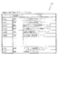
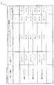
図7に戻ってROM202の説明を続ける。遊技結果設定テーブル202g(図12参照)は、大当たりに当選した場合に、大当たりを示す停止図柄の設定や、大当たり中の特定入賞口(大開放口)65aの動作パターン等の設定値が大当たり種別毎に規定されているデータテーブルである。この遊技結果設定テーブル202gについて、図12を参照して説明する。
Returning to FIG. 7, the description of the
遊技結果設定テーブル202g(図12参照)は、ROM202のアドレス「19D1H」〜「19E8H」の範囲に格納されており、各アドレスに1バイトのデータが格納されている。この遊技結果設定テーブル202g(図12参照)には、各大当たり種別となる判定値(乱数値)の個数(判定値個数)と、複数のLED37aの点灯パターン(表示図柄数)と、特別図柄の停止図柄を示す情報(停止図柄情報)と、特定入賞口(大開放口)65aの作動パターン(大開放口パターン)と、大当たりが終了した後の遊技状態を決定するための情報(オフセット値)とが規定されている。なお、図12には、各データが規定されているROM202のアドレスを括弧書きで記載しているが、アドレスの上位バイトを省略し、下位バイトのみを記載している。
The game result setting table 202g (see FIG. 12) is stored in the addresses “19D1H” to “19E8H” of the
本パチンコ機10では、大当たりに当選することに基づいて、遊技結果設定テーブル202g(図12参照)から、当選した大当たり種別に応じた上記各設定値を、RAM203の各種設定値格納エリア203e(図15参照)に格納する。この各種設定値格納エリア203eの詳細については後述する。そして、各種設定値格納エリア203eに格納された設定値に基づいて、MPU201により大当たりとなる変動パターン演出や大当たりに関する各種制御が行われる。また、各種設定値格納エリア203e(図15参照)には、遊技に関する設定値を格納する記憶領域に加えて、遊技結果設定テーブル202g(図12参照)に規定されているオフセット値を格納するためのオフセット値格納エリアが設けられている。このオフセット値は、大当たり終了後の遊技状態を設定するために用いられる値である。
In the
具体的には、大当たりの終了タイミングと判別された場合に実行される大当たり終了処理(図37参照)において、大当たり終了後の遊技状態に関する各種設定値(特別図柄の高確率状態とするか否かを示す設定値や、普通図柄の時短期間等)を状態設定テーブル202h(図13(a)参照)から選択して各種設定値格納エリア203eに設定するために用いられる。即ち、本実施形態のパチンコ機10では、第1入球口64a、または第2入球口64bへの入球(始動入賞)に伴って取得される乱数値(カウンタ値)そのものを大当たりの終了時点まで保持し続け、その乱数値(カウンタ値)に基づいて大当たり終了後の遊技状態を決定しているわけではなく、第1入球口64a、または第2入球口64bへの入球(始動入賞)に伴って取得される乱数値(カウンタ値)に基づいて選択されるオフセット値のみを大当たり中に保持する構成としている。
Specifically, in the jackpot end process (see FIG. 37) executed when it is determined that the jackpot end timing, various setting values relating to the gaming state after the jackpot end (whether or not to set a high probability state of a special symbol) Is used for selecting from the state setting table 202h (see FIG. 13A) and setting it in various setting
ここで、大当たりとなる乱数値を大当たり当選の際の変動パターン演出中や、その後の大当たり状態中に保持しておく構成とした場合、不正遊技者によって大当たり乱数が読み出されることにより、大当たりとなる乱数値の出現するタイミングが解析され、その解析されたタイミングに基づいて不正に大当たりを引き当てられやすくなる虞がある。これに対して、本実施形態では、取得した乱数値(カウンタ値)を、オフセット値という形に変換して大当たり終了時点まで保持し、そのオフセット値に基づいて大当たり終了後の遊技状態を設定するように構成しているので、特別図柄の大当たりとなる乱数値自体が保持されている期間を短期間に限ることができる。よって、特別図柄の大当たりとなる乱数値を外部から不正に取得され難くすることができるので、大当たりとなる乱数値が出現するタイミングを解析し、その解析したタイミングに基づいて大当たりを引き当てる不正行為を抑制することができる。 Here, if the random number value that is a big hit is configured to be kept during the fluctuation pattern production at the time of winning the big hit or during the subsequent big hit state, it becomes a big hit by reading the big hit random number by an unauthorized player There is a possibility that the timing of appearance of the random number value is analyzed, and that it is easy to illegally win a jackpot based on the analyzed timing. On the other hand, in the present embodiment, the acquired random number value (counter value) is converted into a form of an offset value and held until the jackpot end time, and the gaming state after the jackpot end is set based on the offset value. Since it is configured as described above, the period in which the random number value itself that is a special symbol jackpot is held can be limited to a short time. Therefore, since it is possible to make it difficult for the random number value that is a big jackpot of the special symbol to be illegally acquired from the outside, analyze the timing when the random number value that is a big jackpot appears, and conduct the fraudulent act that allocates the jackpot based on the analyzed timing Can be suppressed.
また、本実施形態のパチンコ機10では、大当たり終了後の遊技状態に関する各種設定値(特別図柄の高確率状態とするか否かを示す設定値や、普通図柄の時短期間等)を保持しておくのではなく、状態設定テーブル202hにおける各種設定値の格納位置を示す値であるオフセット値のみを保持しておく構成としている。RAM203に各種設定値の全てを一時的に記憶しておく記憶エリアを設けておくのではなく、オフセット値を保持する領域を設けておくだけで足りるので、RAM203の記憶領域を効率良く使用することができる。
Further, in the
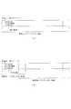
次いで、図13を参照して、ROM202の状態設定テーブル202hについて説明する。この状態設定テーブル202h(図13(a)参照)は、大当たりの終了後に移行し得る遊技状態がオフセット値の順に規定されているテーブルであり、大当たりの終了タイミングであると判別された場合に実行される大当たり終了処理(図37参照)の中で、大当たり終了後の遊技状態を設定するために参照されるデータテーブルである。
Next, the state setting table 202h of the
この状態設定テーブル202h(図13(a)参照)は、ROM202のアドレス1AD8H〜1AE3Hの範囲に格納されており、各アドレスに1バイトのデータが格納されている。この状態設定テーブル202h(図13(a)参照)には、大当たり終了後に特別図柄の高確率状態に移行させるか否かを示す情報(特別図柄の抽選状態)と、大当たり終了後に普通図柄の時短状態に移行させるか否かを示す情報(普通図柄の状態)と、大当たり終了後に付与される普通図柄の時短期間と(時短回数)、変動パターンの態様を選択するための変動パターン選択テーブル202dを大当たり終了後用のテーブルから、状態に応じたテーブルに切り替えるまでに要する特別図柄の抽選回数(変動パターン選択テーブル切替回数)とが規定されている。また、図8には、各データが規定されているROM202のアドレスを括弧書きで記載しているが、ROM202のアドレスの上位バイトを省略し、下位バイトのみを記載している。
This state setting table 202h (see FIG. 13A) is stored in the range of addresses 1AD8H to 1AE3H of the
続いて、図13(b)を参照して、プログラムにおける状態設定テーブル202hの記述内容について説明する。図13(b)は、本実施形態のパチンコ機10の状態設定テーブル202hの記述内容の例を簡略化して示した図である。図13(b)の左側が記述内容の例であり、右側が記述の意味を示している。図13(b)に示す通り、まず、状態設定テーブル202hを示すテーブル名として、「TBL1」というラベルを規定する。ラベル名を規定しておくことで、他の処理において状態設定テーブル202hの先頭アドレスを、「TBL1」と記述するだけで読み出すことができる。即ち、状態設定テーブル202hのアドレス値そのものを他の処理の中で打ち込む必要がない。特に、機種が変わればROM202に記憶される制御処理やデータ数が変わる場合があるので、本パチンコ機10で用いられているプログラムを他の遊技機に転用するような場合、状態設定テーブル202hに割り当てられるアドレス値も変わってしまう場合がある。かかる場合にも、状態設定テーブル202hの先頭アドレスを、「TBL1」というラベルに対応付けておけば、他の機種にプログラムを転用する際に、状態設定テーブル202hを読み出す処理一つ一つにおいてアドレスを打ち込み直す必要がない。よって、プログラムの転用時にプログラムの打ち込みミスが発生することを防止することができるので、プログラムのミスによりパチンコ機10が誤動作してしまうことを抑制することができる。
Next, the description content of the state setting table 202h in the program will be described with reference to FIG. FIG. 13B is a diagram showing a simplified example of the description contents of the state setting table 202h of the
ラベルを規定した行の次の行には、状態設定テーブル202hに規定するためのデータのうち、オフセット値00Hに対応するデータが、格納するアドレスの順番に記述されている。具体的には、アドレス1AD8Hに規定するためのデータである00H、アドレス1AD9Hに規定するためのデータである00H、アドレス1ADAHに規定するためのデータである64H、アドレス1AD9Hに規定するためのデータである64Hが1行にまとめて記述される。なお、オフセット値01Hに対応するデータや、オフセット値02Hに対応するデータに関しても同様に1行にまとめて記述される。つまり、状態設定テーブル202hからデータを読み出してパチンコ機10の遊技状態を設定する1回の処理において、連続的に読み出される一連のデータが1行にまとめて記述される。このように、各オフセット値に対応するデータをそれぞれ1行にまとめて記述することで、各オフセット値に対応するデータに漏れや重複がないか(各オフセット値に対応するデータ数がそれぞれ等しくなっているか)どうかを設計者が容易に確認することができる。よって、データを規定する際に漏れや重複が生じてしまうことにより、パチンコ機10が誤動作してしまうことを抑制することができる。
In the line following the line defining the label, data corresponding to the offset
また、プログラムにおいて、オフセット値00Hに対応するデータを規定した行と、オフセット値01Hに対応するデータを規定した行との間の行に、状態設定テーブル202hの各オフセット値に対応するデータ数として、「D_SIZE」というラベルが定義されている。定義において、「EQU」はイコールを意味し、「$」は現在位置(オフセット値00Hに対応する末尾のデータの次のアドレス)を意味する。つまり、「D_SIZE」が、オフセット値00Hに対応するデータの末尾の次のアドレスと、「TBL1」(状態設定テーブル202hの先頭アドレス)との差分である旨規定している。本実施形態では、状態設定テーブル202hの先頭アドレスが1AD8Hであり、オフセット値00Hに対応するデータの末尾のアドレスが1ADBHであるので、「D_SIZE」は、1ADCHと1AD8Hとの差分である0004Hとなる。
In the program, the number of data corresponding to each offset value in the state setting table 202h is set in a line between a line defining data corresponding to the offset
このように、データ数として「D_SIZE」というラベルを定義することにより、他の処理で状態設定テーブル202hのデータ数を用いる場合に、「D_SIZE」とだけ記述しておけば足りる。即ち、データ数そのものを他の処理の中で規定しておく必要がない。特に、機種が変われば状態設定テーブル202hに規定するデータ数が変わる場合がある。かかる場合にも、データ数として「D_SIZE」というラベルを定義しておけば、他の機種にプログラムを転用する際に、状態設定テーブル202hのデータ数を用いる処理一つ一つにおいてデータ数を書き換える必要がない。よって、プログラムの転用時にプログラムの打ち込みミスが発生することを防止することができるので、プログラムのミスによりパチンコ機10が誤動作してしまうことを抑制することができる。
Thus, by defining the label “D_SIZE” as the number of data, it is sufficient to describe only “D_SIZE” when the number of data in the state setting table 202h is used in other processing. That is, it is not necessary to define the number of data itself in other processes. In particular, if the model changes, the number of data defined in the state setting table 202h may change. Even in such a case, if the label “D_SIZE” is defined as the number of data, the number of data is rewritten in each process using the number of data in the state setting table 202h when the program is transferred to another model. There is no need. Therefore, it is possible to prevent a program input error from occurring when the program is diverted, and thus it is possible to prevent the
更に、本実施形態では、データ数を示すラベルである「D_SIZE」を、データ数の直値で定義するのではなく、ラベル「TBL1」を用いて定義している。これにより、データ数が異なる他の機種にプログラムを転用する場合であっても、「D_SIZE」の定義を書き換える必要が無い。よって、プログラムの転用を行う場合に、「D_SIZE」の定義の書き換えをミスしてしまうことを防止できるので、パチンコ機10が誤動作してしまうことを抑制することができる。
Furthermore, in this embodiment, “D_SIZE”, which is a label indicating the number of data, is not defined by the direct value of the number of data, but is defined using the label “TBL1”. Thereby, even when the program is transferred to another model having a different number of data, it is not necessary to rewrite the definition of “D_SIZE”. Therefore, when the program is diverted, it is possible to prevent mistakes in rewriting the definition of “D_SIZE”, so that the
本実施形態のパチンコ機10では、状態設定テーブル202hの先頭アドレスにのみラベルとして「TBL1」を定義しているが、オフセット値毎(1回の処理において連続的に読み出される一連のデータ毎)に、先頭アドレスに別々のラベルを定義するように構成してもよい。例えば、オフセット値01Hに対応するデータの先頭アドレス(1ADCH)に対してラベル「TBL2」を対応付け、オフセット値02Hに対応するデータの先頭アドレス(1AE0H)に対してラベル「TBL3」を対応付けてもよい。また、この場合において、「D_SIZE」の定義を、「TBL2」と「TBL1」との差分で規定してもよいし、「TBL3」と「TBL2」との差分で規定してもよい。また、「TBL3」と「TBL1」との差分を2で除した値として規定してもよい。
In the
また、各ラベル(「TBL1」や「D_SIZE」等)の名称は本実施形態の名称に限られるものではなく、任意に定めることができる。ラベルの名称は実機の動作に何ら影響を与えないからである。詳述すると、作成したプログラムを、MPU201が理解できる言語(機械語)に翻訳する(アセンブルする)過程で、各処理の中に出現するラベルが、全てアドレスやデータ数そのものの値に変換される。即ち、主制御装置110のMPU201に対してプログラムを反映させた段階で、各種ラベルは全て16進数の機械語に置き換わっている。このため、パチンコ機10の動作にラベルの名称は一切影響しない。
Further, the name of each label (such as “TBL1” and “D_SIZE”) is not limited to the name of the present embodiment, and can be arbitrarily determined. This is because the name of the label does not affect the operation of the actual machine. More specifically, in the process of translating (assembling) the created program into a language (machine language) that can be understood by the
また、アドレスやデータ数にラベルを対応付けて規定するプログラム記述方法は、状態設定テーブル202hに限られるものではなく、例えば、遊技結果設定テーブル202g等、他の処理において参照される可能性があるデータテーブル全てについて、同様の記述方法を踏襲してよい。 Further, the program description method for defining the address and the number of data in association with the label is not limited to the state setting table 202h, and may be referred to in other processes such as the game result setting table 202g. The same description method may be followed for all data tables.
次に、図14を参照して、大当たり終了時クリアテーブル202iについて説明する。大当たり終了時クリアテーブル202iは、ROM202のアドレス「1205H」〜「1212H」の範囲に記憶されたテーブルであり、各アドレスには各種設定値格納エリア203e(図15参照)のアドレスがそれぞれ規定されている。詳細については後述するが、大当たり終了処理の中の1処理であるゼロ設定処理(図38参照)において、主制御装置110のMPU201によって大当たり終了時クリアテーブル202iからROM202のアドレスの並び順に格納データが読み出され、読み出された格納データ(アドレスデータ)の示すアドレスに設定値として「00H」(初期値データ)を設定する。また、大当たり終了時クリアテーブル202iから読み出されたデータが「00H」であった場合は、ゼロ設定処理を終了する。大当たり終了時クリアテーブル202iには設定先アドレスのみを規定し、その設定先アドレスに「00H」を設定するという処理を、MPU201の制御プログラムの中で規定しているので、大当たり終了時クリアテーブル202iのデータ量を減らすことができる。
Next, the jackpot end clear table 202i will be described with reference to FIG. The big hit end clear table 202i is a table stored in the addresses “1205H” to “1212H” of the
次いで、RAM203に設けられた各種設定値格納エリア203eについて説明する。図15は、この各種設定値格納エリア203eを模式的に示した模式図である。図15に示す通り、各種設定値格納エリア203e(図15参照)は、RAM203のアドレス「F000H」〜「F0FFH」の範囲に該当する。この各種設定値格納エリア203e(図15参照)において、RAM203のアドレス「F000H」に割り当てられている発射制御信号設定値格納エリアは、球の発射を制御するための設定値が格納されている記憶領域であり、この領域に格納されている設定値に基づいて遊技領域への球の発射が制御される。
Next, various setting
RAM203のアドレス「F009H」に割り当てられている表示LED設定エリアは、表示LEDを点灯させるための点灯パターンの設定値が格納されている記憶領域であり、この領域に格納されている設定値に基づいて表示LEDを点灯させる。
The display LED setting area assigned to the address “F009H” of the
アドレス「F01DH」,「F01EH」にそれぞれ割り当てられているテスト信号設定エリア1、および、テスト信号設定エリア2は、各種テスト信号を出力するための設定値を格納する記憶領域である。テスト信号としては、例えば、特定入賞口(大開放口)65aの動作テストを行うための信号や、大当たり時の動作テストを行うための信号などがある。テスト信号なので、遊技者がパチンコ機10で遊技を行っている間は信号が出力されない設定(即ち、テスト信号設定エリア1,2共に「00H」が設定値として設定された状態)とされる。
The test
アドレス「F030H」に割り当てられている最大ラウンド数設定エリアは、大当たりのラウンド数を設定するエリアである。本実施形態のパチンコ機10では、全ての大当たりがラウンド数8ラウンドの大当たりであるので、大当たりに当選した場合は、設定値として「08H」が設定される。
The maximum number of rounds setting area assigned to the address “F030H” is an area for setting the number of big hits. In the
RAM203のアドレス「F035H」に割り当てられている遊技状態設定エリアは、現在の遊技状態を示す設定値が格納されている記憶領域であり、例えば、格納されている設定値が「01H」であれば、特別図柄の変動中を示し、「02H」であれば、特別図柄の確定表示中を示し、「03H」であれば、大当たり中、且つ、特定入賞口(大開放口)65aが閉鎖中の状態であることを示し、「04H」であれば、大当たり中、且つ、特定入賞口(大開放口)65aが開放中の状態であることを示す。また、「00H」であれば、上記以外の状態であること(即ち、大当たり終了後から特別図柄の変動が開始されるまでの間の状態や、保留球が無い状態で特別図柄が停止表示されてから一定時間経過した状態)を示している。
The gaming state setting area assigned to the address “F035H” of the
アドレス「F090H」に割り当てられている大当たりフラグは、現在が大当たり状態(特別遊技状態)中であるか否かを示すフラグであり、オンであれば(即ち、格納されているデータが「01H」であれば)、特別図柄の大当たり中であることを示し、オフであれば(即ち、格納されているデータが「00H」であれば)、特別図柄の大当たり中以外の状態(即ち、特別図柄の変動状態や、デモ状態等の状態)を示すものである。また、続くアドレス「F091H」〜「F094H」に割り当てられている記憶領域は、ROM202の状態設定テーブル202hから読み出したデータを設定するための領域である。
The jackpot flag assigned to the address “F090H” is a flag indicating whether or not the current jackpot state (special game state) is on. If the flag is on (that is, the stored data is “01H”). ) Indicates that the special symbol is a big hit, and if it is off (ie, if the stored data is “00H”), a state other than the special symbol big hit (ie, the special symbol). State such as a fluctuation state or a demo state). The storage areas allocated to the subsequent addresses “F091H” to “F094H” are areas for setting data read from the state setting table 202h of the
まず、アドレス「F091H」に割り当てられている確変状態フラグは、現在が特別図柄の確変中であるか否かを示すフラグであり、オンであれば(即ち、格納されているデータが「01H」であれば)、特別図柄の確変中であることを示し、オフであれば(即ち、格納されているデータが「00H」であれば)、特別図柄の低確率状態であることを示している。 First, the probability change state flag assigned to the address “F091H” is a flag indicating whether or not the special symbol is currently being changed, and if it is on (that is, the stored data is “01H”). ) Indicates that the special symbol is being changed, and if it is OFF (that is, if the stored data is “00H”), it indicates that the special symbol is in a low probability state. .
また、アドレス「F092H」に割り当てられている時短状態フラグは、普通図柄の時短中であるか否かを示すと共に、外れ時の変動パターンの態様を選択するためのテーブルを指定するための設定値が格納されている。なお、フラグが「00H」であれば、普通図柄の通常状態であることを示し、フラグが「01H」であれば、普通図柄の時短状態1であることを示す。
Further, the time-short state flag assigned to the address “F092H” indicates whether or not the time of the normal symbol is short, and a setting value for designating a table for selecting a variation pattern mode at the time of detachment Is stored. If the flag is “00H”, it indicates that the normal state is a normal symbol. If the flag is “01H”, it indicates that the normal symbol is in the
アドレス「F093H」に割り当てられている時短状態カウンタは、大当たり終了後に特別図柄の低確率状態へ移行し、且つ、普通図柄の時短状態へと移行した場合に、普通図柄の時短回数が何回分残っているのかを表すカウンタである。なお、大当たり終了後に特別図柄の高確率状態へと移行した場合には、次に大当たりに当選するまで普通図柄の時短状態が継続するが、特別図柄の抽選回数によらず時短状態カウンタは0である。本実施形態のパチンコ機10では、確変状態フラグがオンであるか、時短状態カウンタの値が1以上であれば、普通図柄の時短状態の制御が実行される。
The time-short state counter assigned to the address “F093H” shifts to the low probability state of the special symbol after the jackpot ends, and when the normal symbol shifts to the time-short state, how many times the normal symbol time-short state remains It is a counter that indicates whether or not If the special symbol shifts to a high probability state after the jackpot is over, the normal symbol time-short state continues until the next jackpot is won, but the time-short state counter is 0 regardless of the number of special symbol lotteries. is there. In the
アドレス「F094H」に割り当てられている変動選択状態カウンタは、変動パターン演出を選択するためのテーブルを、別のテーブルに切り替えるまでの、残りの特別図柄の抽選回数を示すカウンタである。このカウンタが1以上であれば、外れ時の変動パターンを選択するためのテーブルとして、大当たり終了後専用の変動パターン選択テーブルが選択される。一方、変動選択状態カウンタの値が0の場合は、時短状態フラグが示す遊技状態に応じたテーブルから変動パターンを決定する。 The variation selection state counter assigned to the address “F094H” is a counter indicating the number of lotteries for the remaining special symbols until the table for selecting the variation pattern effect is switched to another table. If this counter is equal to or greater than 1, a variation pattern selection table dedicated to the end of jackpot is selected as a table for selecting a variation pattern at the time of losing. On the other hand, when the value of the variation selection state counter is 0, the variation pattern is determined from the table corresponding to the gaming state indicated by the time reduction state flag.
アドレス「F095H」に割り当てられているオフセット値格納エリアは、オフセット値を格納するための記憶領域であり、格納されたオフセット値に基づいて状態設定テーブル202hから大当たり終了後の設定値が読み出され、RAM203のアドレス「F091H」〜「F094H」にそれぞれ設定される。このオフセット値は、特別図柄の抽選において大当たりと判別された場合に、遊技結果設定テーブル202gから読み出され、オフセット値格納エリアに記憶される。また、状態設定テーブル202hからの設定値の読み出し、および設定が完了した後で実行されるゼロ設定処理(図38参照)の中で、初期値である「00H」に上書きされる。
The offset value storage area assigned to the address “F095H” is a storage area for storing the offset value, and the set value after the jackpot is read from the state setting table 202h based on the stored offset value. , The addresses “F091H” to “F094H” of the
アドレス「F096H」に割り当てられている大開放口設定エリアは、大当たり中の特定入賞口(大開放口)65aの開放パターンを示す設定値が格納される記憶領域であり、大当たり中に(即ち、大当たりフラグがオンの場合に)参照される。本実施形態のパチンコ機10では、全ての大当たり種別が8ラウンドの大当たりであり、特定入賞口(大開放口)65aの開放パターンは共通であるので、共通の設定値が設定される。
The large opening setting area assigned to the address “F096H” is a storage area in which a setting value indicating an opening pattern of the specific winning opening (large opening) 65a that is a big hit is stored. Referenced when jackpot flag is on). In the
アドレス「F097H」に割り当てられている停止図柄コード情報格納エリアは、特別図柄の抽選結果に基づいて特別図柄の停止図柄の情報を設定するための領域である。特別図柄の抽選結果が外れの場合は、外れに対応した停止図柄を示す停止図柄コードが設定され、抽選結果が当たりの場合は、大当たり種別に応じた停止図柄コードが遊技結果設定テーブル202eから読み出されて設定される。そして、特別図柄の変動終了時に、この停止図柄コード情報格納エリアに設定された設定値に応じた停止図柄が、第1図柄表示装置37に確定表示される。
The stop symbol code information storage area assigned to the address “F097H” is an area for setting stop symbol information of a special symbol based on a special symbol lottery result. If the lottery result of the special symbol is out, a stop symbol code indicating a stop symbol corresponding to the outage is set. If the lottery result is win, the stop symbol code corresponding to the jackpot type is read from the game result setting table 202e. Issued and set. At the end of the change of the special symbol, the stop symbol corresponding to the set value set in the stop symbol code information storage area is fixedly displayed on the first
アドレス「F09FH」〜「F0FFH」までは未使用の領域であり、これらの領域に格納されているデータは「00H」固定とされている。なお、各種設定値格納エリア203eには、上述した以外のアドレスにも様々な設定値が割り当てられている。説明は省略するが、例えば、特定入賞口(大開放口)65aへ入賞した球の個数をカウントする入賞カウンタ等の各種カウンタや、普通図柄の変動演出において、普通図柄の表示を切り替える時間を計測する普通図柄表示切替タイマ等の各種タイマなどが割り当てられている。
Addresses “F09FH” to “F0FFH” are unused areas, and data stored in these areas is fixed to “00H”. Note that various setting values are assigned to addresses other than those described above in the various setting
このように、本実施形態のパチンコ機10では、RAM203のアドレスの上位バイトがF0Hである各種設定値格納エリア203eに、集中的に各種設定値やカウンタ、タイマ等を格納するように構成し、音声ランプ制御装置113等へ出力するコマンド(例えば、変動パターンコマンドや停止種別コマンド等)を格納するためのリングバッファや、特別図柄保留球格納エリア203a、普通図柄保留球数格納エリア203b、スタックエリア等についてはRAM203のアドレスの上位バイトが「F0H」以外のアドレス(例えば、上位バイトが「F1H」であるアドレス)に格納するように構成している。
As described above, the
次いで、図16を参照して、主制御装置110のMPU201に設けられているレジスタ210について説明する。レジスタ210は、ROM202やRAM203からデータを読み出したり、RAM203に設定値を書き込む場合に、アドレスデータや設定値データを一時的に格納したり、格納した設定値に演算処理を行ったりするためのものである。図16に示すように、レジスタ210は、格納したデータに対して演算処理を実行可能なアキュームレータ210aと、アドレスデータや設定値データを格納可能な汎用レジスタ210b1,210b2,210c1,210c2,210d1,210d2と、各種フラグを格納するフラグレジスタ210eと、各種設定値格納エリア203eのアドレスの上位バイト(F0H)を固定値として記憶させておくためのアドレス保持レジスタ210fとが設けられている。なお、アキュームレータ210aは、汎用レジスタ210b1〜210d2と同様に、データを一時的に格納するために用いることもできる。
Next, the
レジスタ210に設けられている各レジスタは、それぞれ1バイトのデータを保持可能に構成されている。また、汎用レジスタ210b1と汎用レジスタ210b2、汎用レジスタ210c1と汎用レジスタ210c2、および汎用レジスタ210d1と汎用レジスタ210d2は、それぞれペアで用いることもできる。即ち、それぞれのペアのレジスタに合計2バイト分のデータを格納することができるように構成されている。2バイト分のデータとしては、例えば、ROM202のアドレスデータや、RAM203のアドレスデータ等が該当する。
Each register provided in the
フラグレジスタ210eは、1バイトの各ビットに異なるフラグが設けられている。設けられているフラグは、例えば、命令を実行した後の演算結果がゼロ以外の値であればオフ、ゼロであればオンとなるゼロフラグや、各種汎用レジスタ210b1〜210d2のいずれかに格納したデータが「00H」以外のデータであればオフ、「00H」であればオンとなるロードフラグ等が設けられている。
The
以下、データの読み書きを行う際の制御について説明する。ここで、本実施形態のパチンコ機10には、主制御装置110の種々の制御を実行させるための様々な命令が設けられており、データの読み書きも、種々の命令の中の一つの命令を用いて実行される。具体的には、例えば、読み出し元と設定先を指定し、転送元に格納されているデータを設定先に転送する転送命令が用意されている。
Hereinafter, control when data is read and written will be described. Here, the
なお、この転送命令では、読み出し元と設定先とのうち、少なくとも一方はレジスタ210に設けられているアキュームレータ210a、または、いずれかの汎用レジスタ(汎用レジスタ210b1〜汎用レジスタ210d2)を指定する必要がある。よって、例えば、ROM202のアドレス「1ADAH」に規定されたデータを読み出して、読み出したデータをRAM203のアドレス「F093H」に格納する場合、例えば、汎用レジスタ210b1を介してデータ転送を行う必要がある。具体的には、まず、アドレス「1ADAH」を読み出し元、汎用レジスタ210b1を設定先とし、転送命令を用いてアドレス「1ADAH」に規定されたデータを汎用レジスタ210b1に格納しておく。そして、次に、汎用レジスタ210b1を読み出し元、アドレス「F093H」を設定先とし、再度転送命令を行って、汎用レジスタ210b1に格納されたデータをアドレス「F093H」に設定する。このように制御することで、ROM202のアドレス「1ADAH」に規定されているデータを、汎用レジスタ210b1を介してRAM203のアドレス「F093H」に転送することができる。
In this transfer instruction, at least one of the reading source and the setting destination needs to designate the
図5に戻って説明を続ける。主制御装置110のMPU201には、アドレスバス、およびデータバスで構成されるバスライン204を介して入出力ポート205が接続されている。入出力ポート205には、払出制御装置111、音声ランプ制御装置113、第1図柄表示装置37、第2図柄表示装置83、第2図柄保留ランプ84、特定入賞口65aの開閉板の下辺を軸として前方側に開閉駆動するための大開放口ソレノイドや電動役物を駆動するためのソレノイドなどからなるソレノイド209が接続され、MPU201は、入出力ポート205を介してこれらに対し各種コマンドや制御信号を送信する。
Returning to FIG. An input /
また、入出力ポート205には、図示しないスイッチ群やセンサ群などからなる各種スイッチ208や、電源装置115に設けられた後述のRAM消去スイッチ回路253が接続され、MPU201は各種スイッチ208から出力される信号や、RAM消去スイッチ回路253より出力されるRAM消去信号SG2に基づいて各種処理を実行する。
The input /
払出制御装置111は、払出モータ216を駆動させて賞球や貸出球の払出制御を行うものである。演算装置であるMPU211は、そのMPU211により実行される制御プログラムや固定値データ等を記憶したROM212と、ワークメモリ等として使用されるRAM213とを有している。
The
払出制御装置111のRAM213は、主制御装置110のRAM203と同様に、MPU211の内部レジスタの内容やMPU211により実行される制御プログラムの戻り先番地などが記憶されるスタックエリアと、各種のフラグおよびカウンタ、I/O等の値が記憶される作業エリア(作業領域)とを有している。RAM213は、パチンコ機10の電源の遮断後においても電源装置115からバックアップ電圧が供給されてデータを保持(バックアップ)できる構成となっており、RAM213に記憶されるデータは、すべてバックアップされる。なお、主制御装置110のMPU201と同様、MPU211のNMI端子にも、停電等の発生による電源遮断時に停電監視回路252から停電信号SG1が入力されるように構成されており、その停電信号SG1がMPU211へ入力されると、停電時処理としてのNMI割込処理(図33参照)が即座に実行される。
The
払出制御装置111のMPU211には、アドレスバス及びデータバスで構成されるバスライン214を介して入出力ポート215が接続されている。入出力ポート215には、主制御装置110や払出モータ216、発射制御装置112などがそれぞれ接続されている。また、図示はしないが、払出制御装置111には、払い出された賞球を検出するための賞球検出スイッチが接続されている。なお、該賞球検出スイッチは、払出制御装置111に接続されるが、主制御装置110には接続されていない。
An input /
発射制御装置112は、主制御装置110により球の発射の指示がなされた場合に、操作ハンドル51の回転操作量に応じた球の打ち出し強さとなるよう球発射ユニット112aを制御するものである。球発射ユニット112aは、図示しない発射ソレノイドおよび電磁石を備えており、その発射ソレノイドおよび電磁石は、所定条件が整っている場合に駆動が許可される。具体的には、遊技者が操作ハンドル51に触れていることをタッチセンサ51aにより検出し、球の発射を停止させるための打ち止めスイッチ51bがオフ(操作されていないこと)を条件に、操作ハンドル51の回動量に対応して発射ソレノイドが励磁され、操作ハンドル51の操作量に応じた強さで球が発射される。
The
音声ランプ制御装置113は、音声出力装置(図示しないスピーカなど)226における音声の出力、ランプ表示装置(電飾部29〜33、表示ランプ34など)227における点灯および消灯の出力、変動演出(変動表示)や連続予告演出といった表示制御装置114で行われる第3図柄表示装置81の表示態様の設定などを制御するものである。演算装置であるMPU221は、そのMPU221により実行される制御プログラムや固定値データ等を記憶したROM222と、ワークメモリ等として使用されるRAM223とを有している。
The sound
音声ランプ制御装置113のMPU221には、アドレスバス及びデータバスで構成されるバスライン224を介して入出力ポート225が接続されている。入出力ポート225には、主制御装置110、表示制御装置114、音声出力装置226、ランプ表示装置227、枠ボタン22などがそれぞれ接続されている。
An input /
音声ランプ制御装置113は、枠ボタン22からの入力を監視し、遊技者によって枠ボタン22が操作された場合は、第3図柄表示装置81で表示されるステージを変更したり、スーパーリーチ時の演出内容を変更したりするように、音声出力装置226、ランプ表示装置227を制御し、また、表示制御装置114へ指示する。ステージが変更される場合は、変更後のステージに応じた背面画像を第3図柄表示装置81に表示させるべく、変更後のステージに関する情報を含めた背面画像変更コマンドを表示制御装置114へ送信する。ここで、背面画像とは、第3図柄表示装置81に表示させる主要な画像である第3図柄の背面側に表示される画像のことである。
The voice
音声ランプ制御装置113は、主制御装置110からのコマンドや、音声ランプ制御装置113に接続された各種装置等の状況に応じてエラーを判定し、そのエラーの種別を含めてエラーコマンドを表示制御装置114へ送信する。表示制御装置114では、受信したエラーコマンドによって示されるエラー種別(例えば、振動エラー)に応じたエラーメッセージ画像を第3図柄表示装置81に遅滞無く表示させる制御が行われる。
The sound
音声ランプ制御装置113のROM222には、第3図柄表示装置81に表示させる変動パターン演出の態様を複数規定した変動パターンテーブル222aが格納されている。主制御装置110から出力される変動パターンコマンドを受信した場合は、対応する変動パターンの態様が、この変動パターンテーブル222aから選択される。また、音声ランプ制御装置113のRAM223には、入賞情報格納エリア223aと、特別図柄保留球数カウンタ223bと、変動開始フラグ223cと、停止種別選択フラグ223dとが少なくとも設けられている。
The
入賞情報格納エリア223aは、1つの実行エリアと、4つのエリア(第1エリア〜第4エリア)とを有しており、これらの各エリアには、入賞情報がそれぞれ格納される。本パチンコ機10では、主制御装置110において始動入賞となった場合に、その始動入賞に応じて取得された第1当たり乱数カウンタC1、第1当たり種別カウンタC2及び変動種別カウンタCS1の各値から、その始動入賞に対応する特別図柄の抽選が行われた場合に得られる各種情報(当否、停止種別、変動パターン)が主制御装置110において予測(推定)され、その予測された各種情報が、主制御装置110から音声ランプ制御装置113へ入賞情報コマンドによって通知される。
The winning
音声ランプ制御装置113では、入賞情報コマンドが受信されると、その入賞情報コマンドにより通知された各種情報(当否、停止種別、変動パターン)が入賞情報として抽出されて、その入賞情報が、入賞情報格納エリア223aに記憶される。より具体的には、抽出された入賞情報が、4つのエリア(第1エリア〜第4エリア)の空いているエリアの中で、エリア番号(第1〜第4)の小さいエリアから順番に記憶される。つまり、エリア番号の小さいエリアほど、時間的に古い入賞に対応するデータが記憶され、第1エリアには、時間的に最も古い入賞に対応するデータが記憶される。
When the winning information command is received, the sound
特別図柄保留球数カウンタ223bは、主制御装置110の特別図柄保留球数カウンタ203cと同様に、第1図柄表示装置37(および第3図柄表示装置81)で行われる変動演出(変動表示)であって、主制御装置110において保留されている変動演出の保留球数(待機回数)を最大4回まで計数するカウンタである。
The special symbol reserved
上述したように、音声ランプ制御装置113は、主制御装置110に直接アクセスして、主制御装置110のRAM203に格納されている特別図柄保留球数カウンタ203cの値を取得することができない。よって、音声ランプ制御装置113では、主制御装置110から送信される保留球数コマンドに基づいて保留球数をカウントし、特別図柄保留球数カウンタ223bにて、その保留球数を管理するようになっている。
As described above, the sound
具体的には、主制御装置110では、第1入球口64a、または第2入球口64bへの入球によって変動表示の保留球数が加算された場合、又は、主制御装置110において特別図柄における変動表示が実行されて保留球数が減算された場合に、加算後または減算後の特別図柄保留球数カウンタ203cの値を示す保留球数コマンドを、音声ランプ制御装置113へ送信する。
Specifically, in the
音声ランプ制御装置113は、主制御装置110より送信される保留球数コマンドを受信すると、その保留球数コマンドから、主制御装置110の特別図柄保留球数カウンタ203cの値を取得して、特別図柄保留球数カウンタ223bに格納する(図41のS1808参照)。このように、音声ランプ制御装置113では、主制御装置110より送信される保留球数コマンドに従って、特別図柄保留球数カウンタ223bの値を更新するので、主制御装置110の特別図柄保留球数カウンタ203cと同期させながら、その値を更新することができる。
When the voice
特別図柄保留球数カウンタ223bの値は、第3図柄表示装置81における保留球数図柄の表示に用いられる。即ち、音声ランプ制御装置113は、保留球数コマンドの受信に応じて、そのコマンドにより示される保留球数を特別図柄保留球数カウンタ223bに格納すると共に、格納後の特別図柄保留球数カウンタ223bの値を表示制御装置114に通知するべく、表示用保留球数コマンドを表示制御装置114に対して送信する。
The value of the special symbol reserved
表示制御装置114では、この表示用保留球数コマンドを受信すると、そのコマンドにより示される保留球数の値、即ち、音声ランプ制御装置113の特別図柄保留球数カウンタ223bの値分の保留球数図柄を第3図柄表示装置81の小領域Ds1に表示するように、画像の描画を制御する。上述したように、特別図柄保留球数カウンタ223bは、主制御装置110の特別図柄保留球数カウンタ203aと同期しながら、その値が変更される。従って、第3図柄表示装置81の小領域Ds1に表示される保留球数図柄の数も、主制御装置110の特別図柄保留球数カウンタ203aの値に同期させながら、変化させることができる。よって、第3図柄表示装置81には、変動表示が保留されている保留球の数を正確に表示させることができる。
When the
変動開始フラグ223cは、主制御装置110から送信される変動パターンコマンドを受信した場合にオンされ(図41のS1802参照)、第3図柄表示装置81における変動表示の設定がなされるときにオフされる(図42のS1902参照)。変動開始フラグ223cがオンになると、受信した変動パターンコマンドから抽出された変動パターンに基づいて、表示用変動パターンコマンドが設定される。
The
ここで設定された表示用変動パターンコマンドは、RAM223に設けられたコマンド送信用のリングバッファに記憶され、MPU221により実行されるメイン処理(図40参照)のコマンド出力処理(S1702)の中で、表示制御装置114に向けて送信される。表示制御装置114では、この表示用変動パターンコマンドを受信することによって、この表示用変動パターンコマンドによって示される変動パターンで、第3図柄表示装置81において第3図柄の変動表示が行われるように、その変動演出の表示制御が開始される。
The display variation pattern command set here is stored in a command transmission ring buffer provided in the
停止種別選択フラグ223dは、主制御装置110から送信される停止種別コマンドを受信した場合にオンされ(図41のS1805参照)、第3図柄表示装置81における停止種別の設定がなされるときにオフされる(図42のS1907参照)。停止種別選択フラグ223dがオンになると、受信した停止種別コマンドから抽出された停止種別(大当たりの場合には大当たり種別)に基づいて、停止種別を設定し、その設定された停止種別が、表示用停止種別コマンドによって、表示制御装置114に通知される。
The stop
表示制御装置114では、この表示用停止種別コマンドを受信することによって、この表示用停止種別コマンドによって示される停止種別に応じた停止図柄が、第3図柄表示装置81で停止表示されるように、変動演出の停止表示が制御される。
In the
RAM223は、その他、主制御装置110より受信したコマンドを、そのコマンドに対応した処理が行われるまで一時的に記憶するコマンド記憶領域(図示せず)などを有している。なお、コマンド記憶領域はリングバッファで構成され、FIFO(First In First Out)方式によってデータの読み書きが行われる。音声ランプ処理装置113のコマンド判定処理(図41参照)が実行されると、コマンド記憶領域に記憶された未処理のコマンドのうち、最初に格納されたコマンドが読み出され、コマンド判定処理によって、そのコマンドが解析されて、そのコマンドに応じた処理が行われる。
In addition, the
表示制御装置114は、音声ランプ制御装置113及び第3図柄表示装置81が接続され、音声ランプ制御装置113より受信したコマンドに基づいて、第3図柄表示装置81における第3図柄の変動表示(変動演出)等を制御するものである。この表示制御装置114の詳細については、図17を参照して後述する。
The
電源装置115は、パチンコ機10の各部に電源を供給するための電源部251と、停電等による電源遮断を監視する停電監視回路252と、RAM消去スイッチ122(図3参照)が設けられたRAM消去スイッチ回路253とを有している。電源部251は、図示しない電源経路を通じて、各制御装置110〜114等に対して各々に必要な動作電圧を供給する装置である。その概要としては、電源部251は、外部より供給される交流24ボルトの電圧を取り込み、各種スイッチ208などの各種スイッチや、ソレノイド209などのソレノイド、モータ等を駆動するための12ボルトの電圧、ロジック用の5ボルトの電圧、RAMバックアップ用のバックアップ電圧などを生成し、これら12ボルトの電圧、5ボルトの電圧及びバックアップ電圧を各制御装置110〜114等に対して必要な電圧を供給する。
The
停電監視回路252は、停電等の発生による電源遮断時に、主制御装置110のMPU201及び払出制御装置111のMPU211の各NMI端子へ停電信号SG1を出力するための回路である。停電監視回路252は、電源部251から出力される最大電圧である直流安定24ボルトの電圧を監視し、この電圧が22ボルト未満になった場合に停電(電源断、電源遮断)の発生と判断して、停電信号SG1を主制御装置110及び払出制御装置111へ出力する。停電信号SG1の出力によって、主制御装置110及び払出制御装置111は、停電の発生を認識し、NMI割込処理を実行する。なお、電源部251は、直流安定24ボルトの電圧が22ボルト未満になった後においても、NMI割込処理の実行に充分な時間の間、制御系の駆動電圧である5ボルトの電圧の出力を正常値に維持するように構成されている。よって、主制御装置110及び払出制御装置111は、NMI割込処理(図33参照)を正常に実行し完了することができる。
The power failure monitoring circuit 252 is a circuit for outputting a power failure signal SG1 to each NMI terminal of the
RAM消去スイッチ回路253は、RAM消去スイッチ122(図3参照)が押下された場合に、主制御装置110へ、バックアップデータをクリアさせるためのRAM消去信号SG2を出力するための回路である。主制御装置110は、パチンコ機10の電源投入時に、RAM消去信号SG2を入力した場合に、バックアップデータをクリアすると共に、払出制御装置111においてバックアップデータをクリアさせるための払出初期化コマンドを払出制御装置111に対して送信する。
The RAM erase
次に、図17を参照して、表示制御装置114の電気的構成について説明する。図17は、表示制御装置114の電気的構成を示すブロック図である。表示制御装置114は、MPU231と、ワークRAM233と、キャラクタROM234と、常駐用ビデオRAM235と、通常用ビデオRAM236と、画像コントローラ237と、入力ポート238と、出力ポート239と、バスライン240,241とを有している。
Next, an electrical configuration of the
入力ポート238の入力側には音声ランプ制御装置113の出力側が接続され、入力ポート238の出力側には、MPU231、ワークRAM233、キャラクタROM234、画像コントローラ237がバスライン240を介して接続されている。画像コントローラ237には、常駐用ビデオRAM235及び通常用ビデオRAM236が接続されると共に、バスライン241を介して出力ポート239が接続されている。また、出力ポート239の出力側には、第3図柄表示装置81が接続されている。
The input side of the
なお、パチンコ機10は、特別図柄の大当たりとなる抽選確率や、1回の特別図柄の大当たりで払い出される賞球数が異なる別機種であっても、第3図柄表示装置81で表示される図柄構成が全く同じ仕様の機種があるので、表示制御装置114は共通部品化されコスト低減が図られている。
It should be noted that the
以下では、先にMPU231、キャラクタROM234、画像コントローラ237、常駐用ビデオRAM235、通常用ビデオRAM236について説明し、次いで、ワークRAM233について説明する。
Hereinafter, the
まず、MPU231は、主制御装置110の変動パターンコマンドに基づく音声ランプ制御装置113から出力された表示用変動パターンコマンドに基づいて、第3図柄表示装置81の表示内容を制御するものである。MPU231は、命令ポインタ231aを内蔵しており、命令ポインタ231aで示されるアドレスに格納された命令コードを読み出してフェッチし、その命令コードに従って各種処理を実行する。MPU231には、電源投入(停電からの復電を含む。以下、同じ。)直後に、電源装置115からシステムリセットがかけられるようになっており、そのシステムリセットが解除されると、命令ポインタ231aは、MPU231のハードウェアによって自動的に「0000H」に設定される。そして、命令コードがフェッチされる度に、命令ポインタ231aは、その値が1ずつ加算される。また、MPU231が命令ポインタの設定命令を実行した場合は、その設定命令により指示されたポインタの値が命令ポインタ231aにセットされる。
First, the
なお、詳細については後述するが、本実施形態において、MPU231によって実行される制御プログラムや、その制御プログラムで使用される各種の固定値データは、第3図柄表示装置81に表示させる画像のデータを記憶させるために設けられたキャラクタROM234に記憶させている。このキャラクタROM234は、小面積で大容量化を図ることが可能なNAND型フラッシュメモリ234aによって構成されているので、画像データだけでなく制御プログラム等を十分に記憶させておくことができる。そして、キャラクタROM234に制御プログラム等を記憶させておけば、制御プログラム等を記憶する専用のプログラムROMを設ける必要がない。よって、表示制御装置114における部品点数を削減することができ、製造コストを削減できるほか、部品数増加による故障発生率の増加を抑制することができる。
Although details will be described later, in the present embodiment, the control program executed by the
一方で、NAND型フラッシュメモリは、特にランダムアクセスを行う場合において読み出し速度が遅くなるという問題点がある。例えば、複数のページに連続して並んだデータの読み出しを行う場合において、2ページ目以降のデータは高速読み出しが可能であるが、最初の1ページ目のデータの読み出しには、アドレスが指定されてからデータが出力されるまでに大きな時間を要する。また、連続していないデータを読み出す場合は、そのデータを読み出す度に大きな時間を要する。このように、NAND型フラッシュメモリは、その読み出しに係る速度が遅いため、MPU231が直接キャラクタROM234から制御プログラムを読み出して各種処理を実行するように構成すると、制御プログラムを構成する命令の読み出しに時間がかかる場合が発生し、MPU231として高性能のプロセッサを用いても、表示制御装置114の処理性能を悪化させてしまうおそれがある。
On the other hand, the NAND flash memory has a problem that the reading speed becomes slow particularly when random access is performed. For example, in the case of reading data continuously arranged on a plurality of pages, the data on the second and subsequent pages can be read at high speed, but an address is specified for reading the data on the first page. It takes a long time for the data to be output. Further, when reading non-continuous data, a long time is required every time the data is read. As described above, since the NAND flash memory is slow in reading, if the
そこで、本実施形態では、MPU231のシステムリセットが解除されると、まず、キャラクタROM234のNAND型フラッシュメモリ234aに記憶されている制御プログラムを、各種データの一時記憶用に設けたワークRAM233に転送して格納する。そして、MPU231はワークRAM233に格納された制御プログラムに従って、各種処理を実行する。ワークRAM233は、後述するようにDRAM(Dynamic RAM)によって構成され、高速でデータの読み書きが行われるので、MPU231は遅滞なく制御プログラムを構成する命令の読み出しを行うことができる。よって、表示制御装置114において高い処理性能を保つことができ、第3図柄表示装置81を用いて、多様化、複雑化させた演出を容易に実行することができる。
Therefore, in this embodiment, when the system reset of the
キャラクタROM234は、MPU231において実行される制御プログラムや、第3図柄表示装置81に表示される画像のデータを記憶したメモリであり、MPU231とバスライン240を介して接続されている。MPU231は、バスライン240を介してシステムリセット解除後にキャラクタROM234に直接アクセスし、そのキャラクタROM234の後述する第2プログラム記憶エリア234a1に記憶された制御プログラムを、ワークRAM233のプログラム格納エリア233aへ転送する。また、バスライン240には画像コントローラ237も接続されており、画像コントローラ237はキャラクタROM234の後述するキャラクタ記憶エリア234a2に格納された画像データを、画像コントローラ237に接続されている常駐用ビデオRAM235や通常用ビデオRAM236へ転送する。
The
このキャラクタROM234は、NAND型フラッシュメモリ234a、ROMコントローラ234b、バッファRAM234c、NOR型ROM234dをモジュール化して構成されている。
The
NAND型フラッシュメモリ234aは、キャラクタROM234におけるメインの記憶部として設けられる不揮発性のメモリであり、MPU231によって実行される制御プログラムの大部分や第3図柄表示装置81を駆動させるための固定値データを記憶する第2プログラム記憶エリア234a1と、第3図柄表示装置81に表示させる画像(キャラクタ等)のデータを格納するキャラクタ記憶エリア234a2とを少なくとも有する。
The
ここで、NAND型フラッシュメモリは、小さな面積で大きな記憶容量が得られる特徴を有しており、キャラクタROM234を容易に大容量化することができる。これにより、本パチンコ機において、例えば2ギガバイトの容量を持つNAND型フラッシュメモリ234aを用いることにより、第3図柄表示装置81に表示させる画像として、多くの画像をキャラクタ記憶エリア234a2に記憶させることができる。よって、遊技者の興趣をより高めるために、第3図柄表示装置81に表示される画像を多様化、複雑化することができる。
Here, the NAND flash memory has a feature that a large storage capacity can be obtained with a small area, and the capacity of the
また、NAND型フラッシュメモリ234aは、多くの画像データをキャラクタ記憶エリア234a2に記憶させた状態で、更に、制御プログラムや固定値データも第2プログラム記憶エリア234a1に記憶させることができる。このように、制御プログラムや固定値データを、従来の遊技機のように専用のプログラムROMを設けて記憶させることなく、第3図柄表示装置81に表示させる画像のデータを記憶させるために設けられたキャラクタROM234に記憶させることができるので、表示制御装置114における部品点数を削減することができ、製造コストを削減できるほか、部品数増加による故障発生率の増加を抑制することができる。
In addition, the
ROMコントローラ234bは、キャラクタROM234の動作を制御するためのコントローラであり、例えば、バスライン240を介してMPU231や画像コントローラ237から伝達されたアドレスに基づいて、NAND型フラッシュメモリ234a等から該当するデータを読み出し、バスライン240を介してMPU231又は画像コントローラ237へ出力する。
The
ここで、NAND型フラッシュメモリ234aは、その性質上、データの書き込み時にエラービット(誤ったデータが書き込まれたビット)が比較的多く発生したり、データを書き込むことができない不良データブロックが発生したりする。そこで、ROMコントローラ234bは、NAND型フラッシュメモリ234aから読み出したデータに対して公知の誤り訂正を施し、また、不良データブロックを避けてNAND型フラッシュメモリ234aへのデータの読み書きが行われるように公知のデータアドレスの変換を実行する。
Here, because of the nature of the
このROMコントローラ234bにより、エラービットを含むNAND型フラッシュメモリ234aから読み出されたデータに対して誤り訂正が行われるので、キャラクタROM234としてNAND型フラッシュメモリ234aを用いたとしても、誤ったデータに基づいてMPU231が処理を行ったり、画像コントローラ237が各種画像を生成したりすることを抑制することができる。
The
また、ROMコントローラ234bによってNAND型フラッシュメモリ234aの不良データブロックが解析され、その不良データブロックへのアクセスが回避されるので、MPU231や画像コントローラ237は、個々のNAND型フラッシュメモリ234aで異なる不良データブロックのアドレス位置を考慮することなく、キャラクタROM234へのアクセスを容易に行うことができる。よって、キャラクタROM234にNAND型フラッシュメモリ234aを用いても、キャラクタROM234へのアクセス制御が複雑化することを抑制することができる。
Further, since the
バッファRAM234cは、NAND型フラッシュメモリ234aから読み出したデータを一時的に記憶するバッファとして用いられるメモリである。MPU231や画像コントローラ237からバスライン240を介してキャラクタROM234に割り振られたアドレスが指定されると、ROMコントローラ234bは、その指定されたアドレスに対応するデータを含む1ページ分(例えば、2キロバイト)のデータがバッファRAM234cにセットされているか否かを判断する。そして、セットされていなければ、その指定されたアドレスに対応するデータを含む1ページ分(例えば、2キロバイト)のデータをNAND型フラッシュメモリ234a(またはNOR型ROM234d)より読み出してバッファRAM234cに一旦セットする。そして、ROMコントローラ234bは、公知の誤り訂正処理を施した上で、指定されたアドレスに対応するデータを、バスライン240を介してMPU231や画像コントローラ237に出力する。
The
このバッファRAM234cは、2バンクで構成されており、1バンク当たりNAND型フラッシュメモリ234aの1ページ分のデータがセットできるようになっている。これにより、ROMコントローラ234bは、例えば、一方のバンクにデータをセットした状態のまま他方のバンクを使用して、NAND型フラッシュメモリ234aのデータを外部に出力したり、MPU231や画像コントローラ237より指定されたアドレスに対応するデータを含む1ページ分のデータをNAND型フラッシュメモリ234aから一方のバンクに転送してセットする処理と、MPU231や画像コントローラ237によって指定されたアドレスに対応するデータを他方のバンクから読み出してMPU231や画像コントローラ237に対して出力する処理とを、並列して処理したりすることができる。よって、キャラクタROM234の読み出しにおける応答性を向上させることができる。
The
NOR型ROM234dは、キャラクタROM234におけるサブの記憶部として設けられる不揮発性のメモリであり、NAND型フラッシュメモリ234aを補完することを目的にそのNAND型フラッシュメモリ234aよりも極めて小容量(例えば、2キロバイト)に構成されている。このNOR型ROM234dには、キャラクタROM234に記憶される制御プログラムのうち、NAND型フラッシュメモリ234aの第2プログラム記憶エリア234a1に記憶されていないプログラム、具体的には、MPU231においてシステムリセット解除後に最初に実行されるブートプログラムの一部を格納する第1プログラム記憶エリア234d1が少なくとも設けられている。
The NOR ROM 234d is a non-volatile memory provided as a sub storage unit in the
ブートプログラムは、第3図柄表示装置81に対する各種制御が実行可能となるように表示制御装置114を起動するための制御プログラムであり、システムリセット解除後にMPU231が先ずこのブートプログラムを実行する。これにより、表示制御装置114において各種制御が実行可能に状態とすることができる。第1プログラム記憶エリア234d1は、このブートプログラムのうち、バッファRAM234cの1バンク分(即ち、NAND型フラッシュメモリ234aの1ページ分)の容量の範囲で、システムリセット解除後にMPU231によって最初に処理すべき命令から所定数の命令(例えば、1ページの容量が2キロバイトであれば、1024ワード(1ワード=2バイト)分の命令)を格納する。なお、第1プログラム記憶エリア234d1に格納されるブートプログラムの命令数は、バッファRAM234cの1バンク分の容量以下に収まっていればよく、表示制御装置114の仕様に合わせて適宜設定されるものであってもよい。
The boot program is a control program for activating the
MPU231は、システムリセットが解除されると、ハードウェアによって命令ポインタ231aの値を「0000H」に設定すると共に、バスライン240に対して命令ポインタ231aにて示されるアドレス「0000H」を指定するように構成されている。一方、キャラクタROM234のROMコントローラ234bは、バスライン240にアドレス「0000H」が指定されたことを検知すると、NOR型ROM234dの第1プログラム記憶エリア234d1に記憶されたブートプログラムをバッファRAM234cの一方のバンクにセットして、対応するデータ(命令コード)をMPU231へ出力する。
When the system reset is released, the
MPU231は、キャラクタROM234から受け取った命令コードをフェッチすると、そのフェッチした命令コードに従って各種処理を実行するとともに、命令ポインタ231aを1だけ加算し、命令ポインタ231aにて示されるアドレスをバスライン240に対して指定する。そして、キャラクタROM234のROMコントローラ234bは、バスライン240によって指定されたアドレスがNOR型ROM234dに記憶されたプログラムを指し示すアドレスである間、先にNOR型ROM234dからバッファRAM234cにセットされたプログラムの中から、対応するアドレスの命令コードをバッファRAM234cより読み出して、MPU231に対して出力する。
When the
ここで、本実施形態において、制御プログラムを全てNAND型フラッシュメモリ234aに格納するのではなく、ブートプログラムのうち、システムリセット解除後にMPU231によって最初に処理すべき命令から所定数の命令をNOR型ROM234dに格納するのは、次の理由による。即ち、NAND型フラッシュメモリ234aは、上述したように、最初の1ページ目のデータの読み出しにおいて、アドレスを指定してからデータが出力されるまでに大きな時間を要する、というNAND型フラッシュメモリ特有の問題がある。
In this embodiment, instead of storing all the control programs in the
このようなNAND型フラッシュメモリ234aに対して制御プログラムを全て格納すると、システムリセット解除後にMPU231が最初に実行すべき命令コードをフェッチするためにMPU231からバスライン240を介してアドレス「0000H」が指定された場合、キャラクタROM234はアドレス「0000H」に対応するデータ(命令コード)を含む1ページ分のデータをNAND型フラッシュメモリ234aから読み出してバッファRAM234cにセットしなければならい。そして、NAND型フラッシュメモリ234aの性質上、その読み出しからバッファRAM234cへのセットに多大な時間を要することになるので、MPU231は、アドレス「0000H」を指定してからアドレス「0000H」に対応する命令コードを受け取るまでに多くの待ち時間を消費する。よって、MPU231の起動にかかる時間が長くなるので、結果として、表示制御装置114における第3図柄表示装置81の制御が即座に開始されない虞がある。
When all the control programs are stored in the
これに対し、NOR型ROMは高速にデータを読み出すことが可能なメモリであるので、ブートプログラムのうち、システムリセット解除後にMPU231によって最初に処理すべき命令から所定数の命令をNOR型ROM234dに格納することによって、システムリセット解除後にMPU231からバスライン240を介してアドレス「0000H」が指定されると、キャラクタROM234は即座にNOR型ROM234dの第1プログラム記憶エリア234d1に記憶されたブートプログラムをバッファRAM234cにセットして、対応するデータ(命令コード)をMPU231へ出力することができる。よって、MPU231は、アドレス「0000H」を指定してから短い時間でアドレス「0000H」に対応する命令コードを受け取ることができ、MPU231の起動を短時間で行うことができる。従って、読み出し速度の遅いNAND型フラッシュメモリ234aで構成されたキャラクタROM234に制御プログラムを格納しても、表示制御装置114における第3図柄表示装置81の制御を即座に開始することができる。
On the other hand, since the NOR-type ROM is a memory that can read data at high speed, a predetermined number of instructions from the first instruction to be processed by the
さて、ブートプログラムは、NAND型フラッシュメモリ234aの第2プログラム記憶エリア234a1に記憶されている制御プログラム、即ち、NOR型ROM234dの第1プログラム記憶エリア234d1に記憶されているブートプログラムを除く制御プログラムや、その制御プログラムで用いられる固定値データ(例えば、後述する表示データテーブル、転送データテーブルなど)を、所定量(例えば、NAND型フラッシュメモリ234aの1ページ分の容量)ずつワークRAM233のプログラム格納エリア233aやデータテーブル格納エリア233bへ転送するようにプログラミングされている。そして、MPU231は、まず、システムリセット解除後に第1プログラム記憶エリア234d1から読み出したブートプログラムに従って、第2プログラム記憶エリア234a1に記憶されている制御プログラムを、第1プログラム記憶エリア234d1のブートプログラムがセットされているバッファRAM234cのバンクとは異なるバンクを使用しながら、所定量だけプログラム格納エリア233aに転送し、格納する。
The boot program is a control program other than the control program stored in the second program storage area 234a1 of the
ここで、第1プログラム記憶エリア234d1に記憶されているブートプログラムは、上述したように、バッファRAM234cの1バンク分に相当する容量で構成されているので、内部バスのアドレスが「0000H」に指定されたことを受けて第1プログラム記憶エリア234d1のブートプログラムがバッファRAM234cにセットされる場合、そのブートプログラムはバッファRAM234cの一方のバンクにのみセットされる。よって、第1プログラム記憶エリア234d1のブートプログラムに従って、第2プログラム記憶エリア234a1に記憶されている制御プログラムをプログラム格納エリア233aに転送する場合は、バッファRAM234cの一方のバンクにセットされた第1プログラム記憶エリア234d1のブートプログラムを残したまま、他方のバンクを使用してその転送処理を実行することができる。従って、その転送処理後に、第1プログラム記憶エリア234d1のブートプログラムを再度バッファRAM234cにセットし直すといった処理が不要であるので、ブート処理に係る時間を短くすることができる。
Here, since the boot program stored in the first program storage area 234d1 has a capacity corresponding to one bank of the
第1プログラム記憶エリア234d1に記憶されているブートプログラムは、第2プログラム記憶エリア234a1に記憶されている制御プログラムを所定量だけプログラム格納エリア233aに転送すると、命令ポインタ231aをプログラム格納エリア233a内の第1の所定番地に設定するようにプログラミングされている。これにより、システムリセット解除後、MPU231によって第2プログラム記憶エリア234a1に記憶されている制御プログラムが所定量だけプログラム格納エリア233aに転送されると、命令ポインタ231aがプログラム格納エリア233aの第1の所定番地に設定される。
When the boot program stored in the first program storage area 234d1 transfers a predetermined amount of the control program stored in the second program storage area 234a1 to the
よって、第2プログラム記憶エリア234a1に記憶されている制御プログラムのうち所定量のプログラムがプログラム格納エリア233aに格納されると、MPU231は、そのプログラム格納エリア233aに格納された制御プログラムを読み出して、各種処理を実行することができる。即ち、MPU231は、第2プログラム記憶エリア234a1を有するNAND型フラッシュメモリ234aから制御プログラムを読み出して命令フェッチするのではなく、プログラム格納エリア233aを有するワークRAM233に転送された制御プログラムを読み出して命令フェッチし、各種処理を実行することになる。後述するように、ワークRAM233はDRAMによって構成されるため、高速に読み出し動作が行われる。よって、制御プログラムの殆どを読み出し速度の遅いNAND型フラッシュメモリ234aに記憶させた場合であっても、MPU231は高速に命令をフェッチし、その命令に対する処理を実行することができる。
Therefore, when a predetermined amount of programs stored in the second program storage area 234a1 is stored in the
ここで、第2プログラム記憶エリア234a1に記憶されている制御プログラムには、第1プログラム記憶エリア234d1に記憶されていない残りのブートプログラムが含まれている。一方、第1プログラム記憶エリア234d1に記憶されているブートプログラムは、ワークRAM233のプログラム格納エリア233aに所定量だけ第2プログラム記憶エリア234a1から転送される制御プログラムの中に、その残りのブートプログラムが含まれるようにプログラミングされていると共に、プログラム格納エリア233aに格納されたその残りのブートプログラムの先頭アドレスを第1の所定番地として命令ポインタ231aを設定するようにプログラミングされている。
Here, the control program stored in the second program storage area 234a1 includes the remaining boot programs that are not stored in the first program storage area 234d1. On the other hand, the boot program stored in the first program storage area 234d1 is the control program transferred from the second program storage area 234a1 by a predetermined amount to the
これにより、MPU231は、第1プログラム記憶エリア234d1に記憶されているブートプログラムによって、第2プログラム記憶エリア234a1に記憶されている制御プログラムを所定量だけプログラム格納エリア233aに転送した後、その転送した制御プログラムに含まれる残りのブートプログラムを実行する。
Accordingly, the
この残りのブートプログラムでは、プログラム格納エリア233aに転送されていない残りの制御プログラムやその制御プログラムで用いられる固定値データ(例えば、後述する表示データテーブル、転送データテーブルなど)を全て第2プログラム記憶エリア234a1から所定量ずつプログラム格納エリア233a又はデータテーブル格納エリア233bに転送する処理を実行する。また、ブートプログラムの最後で、命令ポインタ231aをプログラム格納エリア233a内の第2の所定番地に設定する。具体的には、この第2の所定番地として、プログラム格納エリア233aに格納された、ブートプログラムによるブート処理(図43のS2401参照)の終了後に実行される初期化処理(図43のS2402参照)に対応するプログラムの先頭アドレスを設定する。
In this remaining boot program, the remaining control program that has not been transferred to the
MPU231は、この残りのブートプログラムを実行することによって、第2プログラム記憶エリア234a1に記憶されている制御プログラムや固定値データが全てプログラム格納エリア233a又はデータテーブル格納エリア233bに転送される。そして、ブートプログラムがMPU231により最後まで実行されると、命令ポインタ231aが第2の所定番地に設定され、以後、MPU231は、NAND型フラッシュメモリ234aを参照することなく、プログラム格納エリア233aに転送された制御プログラムを用いて各種処理を実行する。
By executing the remaining boot program, the
よって、制御プログラムの殆どを読み出し速度の遅いNAND型フラッシュメモリ234aによって構成されるキャラクタROM234に記憶させた場合であっても、システムリセット解除後にその制御プログラムをワークRAM233のプログラム格納エリア233aに転送することで、MPU231は、読み出し速度が高速なDRAMによって構成されるワークRAMから制御プログラムを読み出して各種制御を行うことができる。従って、表示制御装置114において高い処理性能を保つことができ、第3図柄表示装置81を用いて、多様化、複雑化させた演出を容易に実行することができる。
Therefore, even when most of the control program is stored in the
また、上述したように、NOR型ROM234dにブートプログラムを全て格納せずに、システムリセット解除後にMPU231によって最初に処理すべき命令から所定数の命令を格納しておき、残りのブートプログラムについては、NAND型フラッシュメモリ234aの第2プログラム記憶エリア234a1に記憶させても、第2プログラム記憶エリア234a1に記憶されている制御プログラムを確実にプログラム格納エリア233aに転送することができる。よって、キャラクタROM234は、極めて小容量のNOR型ROM234dを追加するだけで、MPU231の起動を短時間で行うことができるようになるので、その短時間化に伴うキャラクタROM234のコスト増加を抑制することができる。
Further, as described above, a predetermined number of instructions are stored from the first instruction to be processed by the
画像コントローラ237は、画像を描画し、その描画した画像を所定のタイミングで第3図柄表示装置81に表示させるデジタル信号プロセッサ(DSP)である。画像コントローラ237は、MPU231から送信される後述の描画リスト(図23参照)に基づき1フレーム分の画像を描画して、後述する第1フレームバッファ236bおよび第2フレームバッファ236cのいずれか一方のフレームバッファに描画した画像を展開すると共に、他方のフレームバッファにおいて先に展開された1フレーム分の画像情報を第3図柄表示装置81へ出力することによって、第3図柄表示装置81に画像を表示させる。画像コントローラ237は、この1フレーム分の画像の描画処理と1フレーム分の画像の表示処理とを、第3図柄表示装置81における1フレーム分の画像表示時間(本実施形態では、20ミリ秒)の中で並列処理する。
The
画像コントローラ237は、1フレーム分の画像の描画処理が完了する20ミリ秒毎に、MPU231に対して垂直同期割込信号(以下、「V割込信号」と称す)を送信する。MPU231は、このV割込信号を検出する度に、V割込処理(図45(b)参照)を実行し、画像コントローラ237に対して、次の1フレーム分の画像の描画を指示する。この指示により、画像コントローラ237は、次の1フレーム分の画像の描画処理を実行すると共に、先に描画によって展開された画像を第3図柄表示装置81に表示させる処理を実行する。
The
このように、MPU231は、画像コントローラ237からのV割込信号に伴ってV割込処理を実行し、画像コントローラ237に対して描画指示を行うので、画像コントローラ237は、画像の描画処理および表示処理間隔(20ミリ秒)毎に、画像の描画指示をMPU231より受け取ることができる。よって、画像コントローラ237では、画像の描画処理や表示処理が終了していない段階で、次の画像の描画指示を受け取ることがないので、画像の描画途中で新たな画像の描画を開始したり、表示中の画像情報が格納されているフレームバッファに、新たな描画指示に伴って画像が展開されたりすることを防止することができる。
As described above, the
画像コントローラ237は、また、MPU231からの転送指示や、描画リストに含まれる転送データ情報に基づいて、画像データをキャラクタROM234から常駐用ビデオRAM235や通常用ビデオRAM236に転送する処理も実行する。
The
なお、画像の描画は、常駐用ビデオRAM235および通常用ビデオRAM236に格納された画像データを用いて行われる。即ち、描画の際に必要となる画像データは、その描画が行われる前に、MPU231からの指示に基づき、キャラクタROM234から常駐用ビデオRAM235または通常用ビデオRAM236へ転送される。
The image drawing is performed using image data stored in the
ここで、NAND型フラッシュメモリは、ROMの大容量化を容易にする一方、読み出し速度がその他のROM(マスクROMやEEPROMなど)と比して遅い。これに対し、表示制御装置114では、MPU231が、キャラクタROM234に格納されている画像データのうち一部の画像データを電源投入後に常駐用ビデオRAM235に転送するように、画像コントローラ237に対して指示するよう構成されている。そして、後述するように、常駐用ビデオRAM235に格納された画像データは、上書きされることなく常駐されるように制御される。
Here, the NAND flash memory facilitates an increase in the capacity of the ROM, while the reading speed is slower than other ROMs (mask ROM, EEPROM, etc.). On the other hand, in the
これにより、電源が投入されてから常駐用ビデオRAM235に常駐すべき画像データの転送が終了した後は、常駐用ビデオRAM235に常駐された画像データを使用しながら、画像コントローラ237にて画像の描画処理を行うことができる。よって、描画処理に使用する画像データが常駐用ビデオRAM235に常駐されていれば、画像描画時に読み出し速度の遅いNAND型フラッシュメモリ234aで構成されたキャラクタROM234から対応する画像データを読み出す必要がないため、その読み出しにかかる時間を省略でき、画像の描画を即座に行って第3図柄表示装置81に描画した画像を表示することができる。
Thus, after the transfer of the image data to be resident in the
特に、常駐用ビデオRAM235には、頻繁に表示される画像の画像データや、主制御装置110または表示制御装置114によって表示が決定された後、即座に表示すべき画像の画像データを常駐させるので、キャラクタROM234をNAND型フラッシュメモリ234aで構成しても、第3図柄表示装置81に何らかの画像を表示させるまでの応答性を高く保つことができる。
In particular, the
また、表示制御装置114は、常駐用ビデオRAM235に非常駐の画像データを用いて画像の描画を行う場合は、その描画が行われる前に、キャラクタROM234から通常用ビデオRAM236に対して描画に必要な画像データを転送するように、MPU231が画像コントローラ237に対して指示するよう構成されている。後述するように、通常用ビデオRAM236に転送された画像データは、画像の描画に用いられた後、上書きによって削除される可能性はあるものの、画像描画時には、読み出し速度の遅いNAND型フラッシュメモリ234aで構成されたキャラクタROM234から対応する画像データを読み出す必要がなく、その読み出しにかかる時間を省略できるので、画像の描画を即座に行って第3図柄表示装置81に描画した画像を表示することができる。
Further, when the image is drawn using the non-resident image data in the
また、通常用ビデオRAM236にも画像データを格納することによって、全ての画像データを常駐用ビデオRAM235に常駐させておく必要がないため、大容量の常駐用ビデオRAM235を用意する必要がない。よって、常駐用ビデオRAM235を設けたことによるコスト増大を抑えることができる。
Further, by storing the image data in the
画像コントローラ237は、NAND型フラッシュメモリ234aの1ブロック分の容量である132キロバイトのSRAMによって構成されたバッファRAM237aを有している。
The
MPU231が、転送指示や描画リストの転送データ情報によって画像コントローラ237に対して行う画像データの転送指示には、転送すべき画像データが格納されているキャラクタROM234の先頭アドレス(格納元先頭アドレス)と最終アドレス(格納元最終アドレス)、転送先の情報(常駐用ビデオRAM235及び通常用ビデオRAM236のいずれに転送するかを示す情報)、及び転送先(常駐用ビデオRAM235又は通常用ビデオRAM236)の先頭アドレスが含まれる。なお、格納元最終アドレスに代えて、転送すべき画像データのデータサイズを含めてもよい。
In the image data transfer instruction that the
画像コントローラ237は、この転送指示の各種情報に従って、キャラクタROM234の所定アドレスから1ブロック分のデータを読み出して一旦バッファRAM237aに格納し、常駐用ビデオRAM235または通常用ビデオRAM236の未使用時に、バッファRAM237aに格納された画像データを常駐RAM235または通常用ビデオRAM236に転送する。そして、転送指示により示された格納元先頭アドレスから格納元最終アドレスに格納された画像データが全て転送されるまで、その処理を繰り返し実行する。
The
これにより、キャラクタROM234から時間をかけて読み出された画像データを一旦そのバッファRAM237aに格納し、その後、その画像データをバッファRAM237aから常駐用ビデオRAM235又は通常用ビデオRAM236へ短時間で転送することができる。よって、キャラクタROM234から画像データが常駐用ビデオRAM235又は通常用ビデオRAM236へ転送される間に、常駐用ビデオRAM235又は通常用ビデオRAM236が、その画像データの転送で長時間占有されるのを防止することができる。従って、画像データの転送により常駐用ビデオRAM235や通常用ビデオRAM236が占有されることで、画像の描画処理にそれらのビデオRAM235,236が使用できず、結果として必要な時間までに画像の描画や、第3図柄表示装置81への表示が間に合わなくなることを防止することができる。
Thus, the image data read from the
また、バッファRAM234cから常駐用ビデオRAM235又は通常用ビデオRAM236への画像データへの転送は、画像コントローラ237によって行われるので、常駐用ビデオRAM235及び通常用ビデオRAM236が画像の描画処理や第3図柄表示装置81への表示処理に未使用である期間を容易に判定することができ、処理の単純化を図ることができる。
In addition, since the
常駐用ビデオRAM235は、キャラクタROM234より転送された画像データが、電源投入中、上書きされることがなく保持され続けるように用いられ、電源投入時主画像エリア235a、背面画像エリア235c、キャラクタ図柄エリア235e、エラーメッセージ画像エリア235fが設けられているほか、電源投入時変動画像エリア235b、第3図柄エリア235dが少なくとも設けられている。
The
電源投入時主画像エリア235aは、電源が投入されてから常駐用ビデオRAM235に常駐すべき全ての画像データが格納されるまでの間に第3図柄表示装置81に表示する電源投入時主画像に対応するデータを格納する領域である。また、電源投入時変動画像エリア235bは、第3図柄表示装置81に電源投入時主画像が表示されている間に遊技者によって遊技が開始され、第1入球口64a、または第2入球口64bへの入球が検出された場合に、主制御装置110において行われた抽選結果を変動演出によって表示する電源投入時変動画像に対応する画像データを格納する領域である。
The power-on
MPU231は、電源部251から電源供給が開始されたときに、キャラクタROM234から電源投入時主画像および電源投入時変動画像に対応する画像データを電源投入時主画像エリア235aへ転送するように、画像コントローラ237へ転送指示を送信する(図43のS2403,S2404参照)。
When the power supply from the
ここで、図18を参照して、電源投入時変動画像について説明する。図18は、表示制御装置114が電源投入直後において、常駐用ビデオRAM235に対して格納すべき画像データをキャラクタROM234から転送している間に、第3図柄表示装置81にて表示される電源投入時画像を説明する説明図である。
Here, with reference to FIG. 18, the power-on variation image will be described. FIG. 18 shows that the
表示制御装置114は、電源投入直後に、キャラクタROM234から電源投入時主画像および電源投入時変動画像に対応する画像データを、電源投入時主画像エリア235aおよび電源投入時変動画像エリア235bへ転送すると、続いて、常駐用ビデオRAM235に格納すべき残りの画像データを、キャラクタROM234から常駐用ビデオRAM235に対して転送する。この残りの画像データの転送が行われている間、表示制御装置114は、先に電源投入時主画像エリア235aに格納された画像データを用いて、図18(a)に示す電源投入時主画像を第3図柄表示装置81に表示させる。
The
このとき、変動開始の指示コマンドである主制御装置110からの変動パターンコマンドに基づき音声ランプ制御装置113から送信される表示用変動パターンコマンドを受信すると、表示制御装置114は、図18(b)に示すように、電源投入時主画像の表示画面上に、画面に向かって右下の位置に「○」図柄の電源投入時変動画像と、図18(c)に示すように、「○」図柄と同位置に「×」図柄の電源投入時変動画像とを、変動期間中、交互に繰り返して表示する。そして、主制御装置110からの変動パターンコマンドや停止種別コマンドに基づき音声ランプ制御装置113から送信される表示用変動パターンコマンドおよび表示用停止種別コマンドから、主制御装置110にて行われた抽選の結果を判断し、「特別図柄の大当たり」である場合は図18(b)に示す画像を変動演出の停止後に一定期間表示させ、「特別図柄の外れ」である場合は図17(c)に示す画像を変動演出の停止後に一定期間表示させる。
At this time, when the display variation pattern command transmitted from the sound
MPU231は、常駐用ビデオRAM235に常駐すべき全ての画像データが常駐用ビデオRAM235に対して転送されるまで、画像コントローラ237に対し、電源投入時主画像エリア235aに格納された画像データを用いて電源投入時主画像の描画を行うよう指示する。これにより、残りの常駐すべき画像データが常駐用ビデオRAM235に転送されている間、遊技者やホール関係者は、第3図柄表示装置81に表示された電源投入時主画像を確認することができる。よって、表示制御装置114は、電源投入時主画像を第3図柄表示装置81に表示させている間に、時間をかけて残りの常駐すべき画像データをキャラクタROM234から常駐用ビデオRAM235に転送することができる。また、遊技者等は、電源投入時主画像が第3図柄表示装置81に表示されている間、何らかの処理が行われていることを認識できるので、残りの常駐用ビデオRAM235に常駐すべき画像データが、キャラクタROM234から常駐用ビデオRAM235に転送されるまでの間、動作が停止していないか、といった不安を持つことなく、常駐用ビデオRAM235への画像データの転送が完了するまで待機することができる。
The
また、製造時の工場等における動作チェックにおいても、電源投入時主画像がすぐに第3図柄表示装置81に表示されることによって、第3図柄表示装置81が電源投入によって問題なく動作が開始されていることをすぐに確認することができ、更に、キャラクタROM234に読み出し速度の遅いNAND型フラッシュメモリ234aを用いることにより動作チェックの効率が悪化することを抑制できる。
Also in the operation check at the factory or the like at the time of manufacturing, the main image at the time of turning on the power is immediately displayed on the third
また、電源投入時主画像が第3図柄表示装置81に表示されている間に遊技者が遊技を開始し、第1入口球64a、または第2入球口64bへの入球が検出された場合は、電源投入時変動画像エリア235bに常駐された電源投入時変動画像に対応する画像データを用いて電源投入時変動画像が描画され、図18(b)及び(c)に示す画像が交互に第3図柄表示装置81に表示されるように、MPU231から画像コントローラ237に対して指示される。これにより、電源投入時変動画像を用いて簡単な変動演出を行うことができる。よって、遊技者は、電源投入時主画像が第3図柄表示装置81に表示されている間であっても、その簡単な変動演出によって確実に抽選が行われたことを確認することができる。
In addition, the player started playing while the main image was displayed on the third
また、電源投入時主画像が第3図柄表示装置81に表示される段階で、すでに電源投入時変動演出画像に対応する画像データが電源投入時変動画像エリア235bに常駐されているので、電源投入時主画像が第3図柄表示装置81に表示されている間に第1入口球64に入球が検出された場合は、対応する変動演出を第3図柄表示装置81に即座に表示させることができる。
Further, when the main image at power-on is displayed on the third
図17に戻って、説明を続ける。背面画像エリア235cは、第3図柄表示装置81に表示される背面画像に対応する画像データを格納する領域である。ここで、図19及び図20を参照して、背面画像と、その背面画像のうち、背面画像エリア235cに格納される背面画像の範囲について説明する。図19及び図20は、3種類の背面画像と、各背面画像に対して常駐用ビデオRAM235の背面画像エリア235cに格納される背面画像の範囲を説明する説明図であり、図19(a)は、「街中ステージ」に対応する背面Aに対して、図19(b)は、「空ステージ」に対応する背面Bに対して、図20は、「島ステージ」に対応する背面Cに対してそれぞれ示したものである。
Returning to FIG. 17, the description will be continued. The
各背面A〜Cのうち、背面A及びBに対応する背面画像は、図19に示すように、いずれも第3図柄表示装置81において表示される表示領域よりも水平方向に長い画像が、キャラクタROM234に用意されている。画像コントローラ237は、その画像を水平方向に左から右へスクロールさせながら背面画像が第3図柄表示装置81に表示されるように、画像の描画をおこなう。
Among the back surfaces A to C, the back images corresponding to the back surfaces A and B are images that are longer in the horizontal direction than the display area displayed on the third
各背面A及びBに用意された画像(以下、「スクロール用画像」と称す。)は、いずれも位置aおよび位置cのところで背面画像が連続するように画像が構成されている。そして、位置cから位置dの間の画像および位置aから位置a’の間の画像は、表示領域の水平方向の幅分の画像によって構成されており、位置cから位置dの間にある画像が表示領域として第3図柄表示装置81に表示された後に、位置aから位置a’の間にある画像を表示領域として第3図柄表示装置81に表示させると、第3図柄表示装置81にスムーズなつながりで背面画像がスクロール表示されるようになっている。
The images prepared on the rear surfaces A and B (hereinafter referred to as “scroll images”) are configured such that the rear images are continuous at the positions a and c. The image between the position c and the position d and the image between the position a and the position a ′ are composed of images corresponding to the horizontal width of the display area, and an image between the position c and the position d. Is displayed on the third
遊技者によって枠ボタン22が操作されてステージが「街中ステージ」または「空ステージ」に変更されると、MPU231は、対応する背面画像のまず位置aから位置a’の間を表示領域の初期位置として設定し、その初期位置の画像が第3図柄表示装置81に表示されるように、画像コントローラ237を制御する。そして、時間の経過とともに、表示領域をスクロール用画像に対して左から右に移動させ、順次その表示領域が第3図柄表示装置81に表示されるように画像コントローラ237を制御し、更に、表示領域が位置cから位置dの間の画像に到達した場合、再び表示領域を位置aから位置a’の画像として第3図柄表示装置81に表示されるように画像コントローラ237を制御する。よって、第3図柄表示装置81には、位置a〜位置cの間の画像を、左方向に向かって流れるように、スムーズなつながりで繰り返しスクロールされて表示させることができる。
When the player operates the
一方、背面Cにおける背面画像は、図20に示すように、時間の経過とともに、図20の(a)→(b)→(c)→(a)→・・・の順で、第3図柄表示装置81に表示される。具体的には、背面Cは、島にそびえる山の画像と、山のふもとに広がる砂浜の画像と、島を囲む海の画像とが、その表示される位置が固定された状態で第3図柄表示装置81に表示される。一方、山の上に広がる空の画像は、その色調が時間経過とともに変化する。
On the other hand, as shown in FIG. 20, the back image on the back C is the third pattern in the order of (a) → (b) → (c) → (a) →. It is displayed on the
遊技者による枠ボタン22の操作によりステージが「島ステージ」に変更されると、背面Cの初期背面画像として、図20(a)に示す背面画像が表示される。この図20(a)に示す背面画像では、朝やけを示すオレンジ色の空が表示される。そして、時間の経過とともに空の色調がオレンジ色から徐々に鮮やかな青色に変化して、所定時間経過後、図20(b)に示す背面画像が表示される。図20(b)に示す背面画像では、昼を示す鮮やかな青色の空が表示される。次に、時間の経過とともに空の色調が鮮やかな青色から徐々に黒色に変化して、所定時間経過後、図20(c)に示す背面画像が表示される。図20(c)に示す背面画像では、夜を示す黒色の空が表示される。その後、時間の経過とともに空の色調が黒色から徐々に白みはじめ更にオレンジ色に変化する。そして、所定時間経過後、図20(a)に示す背面画像に戻って、再び図20(a)〜(c)の背面画像が第3図柄表示装置81に表示される。
When the stage is changed to “island stage” by the player's operation of the
次いで、各背面画像において、背面画像エリア235cに格納される背面画像の範囲について説明する。初期ステージである街中ステージに対応する背面Aは、図19(a)に示すように、その背面Aの全範囲、即ち、位置aから位置dに対応する画像データが全て常駐用ビデオRAM235の背面画像エリア235cに格納される。通常、初期ステージである街中ステージを表示させたまま、ステージを変更せずに遊技が行われる場合が多いので、多頻度で表示される街中ステージに対応する背面Aの画像データを全て背面画像エリア235cに常駐させておくことで、キャラクタROM234へのデータアクセス回数を減らすことができ、表示制御装置114にかかる負荷を軽減することができる。
Next, the range of the back image stored in the
一方、空ステージに対応する背面Bは、図19(b)に示すように、その背面の一部領域、即ち、位置aから位置bの間の画像に対応する画像データだけを常駐用ビデオRAM235の背面画像エリア235cに格納する。また、島ステージに対応する背面Cは、図20(a)を含み、図20(b)を除く図20(a)〜(b)の間の背面画像に対応する画像データが、電源投入後の立ち上げ処理の中で常駐用ビデオRAM235の背面画像エリア235cに格納され、常駐される。
On the other hand, as shown in FIG. 19B, the rear surface B corresponding to the empty stage stores only image data corresponding to the partial area of the rear surface, that is, the image between the position a and the position b. Is stored in the
ここで、ステージを変更するために遊技者による行われる枠ボタン22の操作は、遊技者の意思に基づき任意のタイミングで行われるものであるので、任意のタイミングで枠ボタン22が操作されても即座に背面画像を変更するためには、全ての背面画像について全範囲の画像データを常駐用ビデオRAM235に常駐させておくことが理想的であるが、そのようにすると常駐用ビデオRAM235として非常に大きな容量のRAMを用いなければならず、コストの増大につながるおそれがある。
Here, since the operation of the
これに対し、本パチンコ機10では、ステージが変更された場合に最初に表示される背面画像の初期位置を、位置aから位置a’の範囲または図20(a)〜(b)の範囲に固定し、その初期位置を含む位置aから位置bの間の画像または図20(a)〜(b)の間の画像に対応する画像データを常駐用ビデオRAM235の背面画像エリア235cに格納しておくので、キャラクタROM234を読み出し速度の遅いNAND型フラッシュメモリ234aで構成しても、遊技者による枠ボタン22の操作によって任意のタイミングでステージが変更された場合に、常駐用ビデオRAM235の背面画像エリア235cに常駐されている画像データを用いることによって、即座にその背面Bや背面Cの初期位置を第3図柄表示装置81に表示させることができ、また、時間経過とともにスクロール表示または色調を変化させながら表示させることができる。また、背面Bおよび背面Cについては、一部範囲の画像に対応する画像データだけを格納するので、常駐用ビデオRAM235の記憶容量の増大を抑制でき、コストの増大を抑えることができる。
On the other hand, in the
また、背面Bは、初期位置の画像が表示された後、常駐用ビデオRAM235の背面画像エリア235cに常駐された画像データを用いて位置aから位置bの範囲を左から右に向けてスクロールさせている間に、位置b’から位置dの画像に対応する画像データをキャラクタROM234から通常用ビデオRAM236へ転送完了できるように、その位置aから位置bの範囲が設定されている。これにより、位置aから位置bの範囲をスクロールさせる間に位置b’から位置dの画像データを通常用ビデオRAM236へ転送できるので、常駐用ビデオRAM235の背面画像エリア235cに格納された画像データを用いて位置aから位置bの範囲をスクロールさせた後、遅滞なく通常用ビデオRAM236に格納された背面画像に対応する画像データを用いて、位置b’から位置dの範囲をスクロールさせて第3図柄表示装置81に表示させることができる。
On the back B, after the image at the initial position is displayed, the range from the position a to the position b is scrolled from the left to the right using the image data resident in the
同様に、背面Cは、初期位置の画像が表示された後、常駐用ビデオRAM235の背面画像エリア235cに常駐された画像データを用いて図20(a)〜(b)の画像を表示させている間に、図20(b)〜(c)および図20(c)〜(a)に対応する画像の画像データがキャラクタROM234から通常用ビデオRAM236へ転送が完了できるように、図20(a)〜(b)の範囲が設定されている。これにより、図20(a)〜(b)の画像を表示させている間に図20(b)〜(c)および図20(c)〜(a)の画像に対応する画像データを通常用ビデオRAM236へ転送できるので、常駐用ビデオRAM235の背面画像エリア235cに常駐された画像データを用いて図20(a)〜(b)の画像を表示させた後、遅滞なく通常用ビデオRAM236に格納された背面画像に対応する画像データを用いて、図20(b)〜(c)および図20(c)〜(a)の画像を時間経過とともに、順次、第3図柄表示装置81に表示させることができる。
Similarly, after the image at the initial position is displayed on the rear surface C, the images shown in FIGS. 20A to 20B are displayed using the image data resident in the
なお、背面B及び背面Cにおいて、通常用ビデオRAM236に格納される画像データは、通常用ビデオRAM236の画像格納エリア236a(図17参照)に設けられた背面画像専用のサブエリアに格納される。これにより、背面画像専用のサブエリアに格納された背面画像データが、他の画像データによって上書きされることがないので、背面画像を確実に表示させることができる。
Note that on the back B and the back C, the image data stored in the
また、背面Bにおいて、常駐用ビデオRAM235の背面画像エリア235cに格納される画像データと、通常用ビデオRAM236に格納される画像データとでは、位置b’から位置bの間の画像に対応する画像データが重複して格納される。そして、MPU231による画像コントローラ237の制御により、常駐用ビデオRAM235の背面画像エリア235cに格納された画像データを用いて位置bまでの画像を第3図柄表示装置81に表示させ、次いで、通常用ビデオRAM236に格納された画像データを用いて位置b’からの画像を第3図柄表示装置81に表示させることで、第3図柄表示装置81にスムーズなつながりで背面画像がスクロール表示されるようになっている。
Further, on the back surface B, the image data stored in the
更に、MPU231は、通常用ビデオRAM236の画像データを用いて、位置cから位置dの間の画像を表示領域として第3図柄表示装置81に表示されるように画像コントローラ237を制御すると、次いで、MPU231は、常駐用ビデオRAM235の背面画像エリア235cの画像データを用いて、位置aから位置a’の間の画像を表示領域として第3図柄表示装置81に表示されるように画像コントローラ237を制御する。これにより、第3図柄表示装置81には、位置a〜位置cの間の画像が、左方向に向かって流れるように、スムーズなつながりで繰り返しスクロールされて表示させることができる。
Further, the
図17に戻って、説明を続ける。第3図柄エリア235dは、第3図柄表示装置81に表示される変動演出において使用される第3図柄を常駐するためのエリアである。即ち、第3図柄エリア235dには、第3図柄である「0」から「9」の数字を付した上述の10種類の主図柄(図4参照)に対応する画像データが常駐される。これにより、第3図柄表示装置81にて変動演出を行う場合、逐一キャラクタROM234から画像データを読み出す必要がないので、キャラクタROM234にNAND型フラッシュメモリ234aを用いても、第3図柄表示装置81において素早く変動演出を開始することができる。よって、第1入球口64a、または第2入球口64bへの入球が発生してから、第1図柄表示装置37では変動演出が開始されているにも関わらず、第3図柄表示装置81において変動演出が即座に開始されないような状態が発生するのを抑制することができる。
Returning to FIG. 17, the description will be continued. The
また、第3図柄エリア235dには、「0」から「9」の数字が付されていない主図柄として、木箱といった後方図柄からなる主図柄や、後方図柄とかんな、風呂敷、ヘルメット等のキャラクタを模した付属図柄とからなる主図柄に対応する画像データも常駐される。これらの画像データは、一の変動演出が停止してから所定時間経過しても、始動入賞に伴う次の変動演出が開始されない場合に、第3図柄表示装置81に表示されるデモ演出に用いられる。これにより、デモ演出が第3図柄表示装置81に表示されると、そのデモ演出において、第3図柄として数字の付されていない主図柄が表示される。よって、遊技者は、数字の付されていない主図柄を第3図柄表示装置81の表示画像から視認することによって、当該パチンコ機10がデモ状態にあることを容易に認識することができる。
In addition, in the
キャラクタ図柄エリア235eは、第3図柄表示装置81に表示される各種演出で使用されるキャラクタ図柄に対応する画像データを格納する領域である。本パチンコ機10では、様々なキャラクタが各種演出にあわせて表示されるようになっており、これらに対応するデータがキャラクタ図柄エリア235eに常駐されることにより、表示制御装置114は、音声ランプ制御装置113より受信したコマンドの内容に基づいてキャラクタ図柄を変更する場合、キャラクタROM234から対応の画像データを新たに読み出すのではなく、常駐用ビデオRAM235のキャラクタ図柄エリア235eに予め常駐されている画像データを読み出すことによって、画像コントローラ237にて所定の画像を描画できるようになっている。これにより、キャラクタROM234から対応の画像データを読み出す必要がないので、キャラクタROM234に読み出し速度の遅いNAND型フラッシュメモリ234aを用いても、キャラクタ図柄を即座に変更することができる。
The character symbol area 235e is an area for storing image data corresponding to character symbols used in various effects displayed on the third
エラーメッセージ画像エリア235fは、パチンコ機10内にエラーが発生した場合に表示されるエラーメッセージに対応する画像データを格納する領域である。本パチンコ機10では、例えば、遊技盤13の裏面に取り付けられた振動センサ(図示せず)の出力から、音声ランプ制御装置113によって振動を検出すると、音声ランプ制御装置113は振動エラーの発生をエラーコマンドによって表示制御装置114に通知する。また、音声ランプ制御装置113により、その他のエラーの発生が検出された場合にも、音声ランプ制御装置113は、エラーコマンドによって、そのエラーの発生をそのエラー種別と共に表示制御装置114へ通知する。表示制御装置114では、エラーコマンドを受信すると、その受信したエラーに対応するエラーメッセージを第3図柄表示装置81に表示させるように構成されている。
The error
ここで、エラーメッセージは、遊技者の不正防止やエラーに対する遊技者の保護の観点から、エラーの発生とほぼ同時に表示されることが求められる。本パチンコ機10では、エラーメッセージ画像エリア235fに、各種エラーメッセージに対応する画像データが予め常駐されているので、表示制御装置114は、受信したエラーコマンドに基づいて、常駐用ビデオRAM235のエラーメッセージ画像エリア235fに予め常駐されている画像データを読み出すことによって、画像コントローラ237にて各エラーメッセージ画像を即座に描画できるようになっている。これにより、キャラクタROM234から逐次エラーメッセージに対応する画像データを読み出す必要がないので、キャラクタROM234に読み出し速度の遅いNAND型フラッシュメモリ234aを用いても、エラーコマンドを受信してから対応するエラーメッセージを即座に表示させることができる。
Here, the error message is required to be displayed almost simultaneously with the occurrence of the error from the viewpoint of preventing the player's fraud and protecting the player against the error. In the
通常用ビデオRAM236は、データが随時上書きされ更新されるように用いられるもので、画像格納エリア236a、第1フレームバッファ236b、第2フレームバッファ236cが少なくとも設けられている。
The
画像格納エリア236aは、第3図柄表示装置81に表示させる画像の描画に必要な画像データのうち、常駐用ビデオRAM235に常駐されていない画像データを格納するためのエリアである。画像格納エリア236aは、複数のサブエリアに分割されており、サブエリア毎に、そのサブエリアに格納される画像データの種別が予め定められている。
The
MPU231は、常駐用ビデオRAM235に常駐されていない画像データのうち、その後の画像の描画で必要となる画像データを、キャラクタROM234から通常用ビデオRAM236の画像格納エリア236aに設けられたサブエリアのうち、その画像データの種別を格納すべき所定のサブエリアに転送するように、画像コントローラ237に対して指示をする。これにより画像コントローラ237は、MPU231により指示された画像データをキャラクタROM234から読み出し、バッファRAM237aを介して、画像格納エリア236aの指定された所定のサブエリアにその読み出した画像データを転送する。
The
なお、画像データの転送指示は、MPU231が画像コントローラ237に対して画像の描画を指示する後述の描画リストの中に、転送データ情報を含めることによって行われる。これにより、MPU231は、画像の描画指示と、画像データの転送指示とを、描画リストを画像コントローラ237に送信するだけで行うことができるので、処理負荷を低減することができる。
The image data transfer instruction is performed when the
第1フレームバッファ236bおよび第2フレームバッファ236cは、第3図柄表示装置81に表示すべき画像を展開するためのバッファである。画像コントローラ237は、MPU231からの指示に従って描画した1フレーム分の画像を、第1フレームバッファ236bおよび第2フレームバッファ236cのいずれか一方のフレームバッファに書き込むことによって、そのフレームバッファに1フレーム分の画像を展開すると共に、その一方のフレームバッファに画像を展開している間、他方のフレームバッファから先に展開された1フレーム分の画像情報を読み出し、駆動信号と共に第3図柄表示装置81に対してその画像情報を送信することによって、第3図柄表示装置81に、その1フレーム分の画像を表示させる処理を実行する。
The
このように、フレームバッファとして、第1フレームバッファ236bおよび第2フレームバッファ236cの2つを設けることによって、画像コントローラ237は、一方のフレームバッファに描画した1フレーム分の画像を展開しながら、同時に、他方のフレームバッファから先に展開された1フレーム分の画像を読み出して、第3図柄表示装置81にその読み出した1フレーム分の画像を表示させることができる。
As described above, by providing the
そして、1フレーム分の画像を展開するフレームバッファと、第3図柄表示装置81に画像を表示させるために1フレーム分の画像情報が読み出されるフレームバッファとは、1フレーム分の画像の描画処理が完了する20ミリ秒毎に、MPU231によって、それぞれ第1フレームバッファ236bおよび第2フレームバッファ236cのいずれかが交互に入れ替えて指定される。
A frame buffer for developing an image for one frame and a frame buffer for reading out image information for one frame for displaying an image on the third
即ち、あるタイミングで、1フレーム分の画像を展開するフレームバッファとして第1フレームバッファ236bが指定され、1フレーム分の画像情報が読み出されるフレームバッファとして第2フレームバッファ236cが指定されて、画像の描画処理および表示処理が実行されると、1フレーム分の画像の描画処理が完了する20ミリ秒後に、1フレーム分の画像を展開するフレームバッファとして第2フレームバッファ236cが指定され、1フレーム分の画像情報が読み出されるフレームバッファとして第1フレームバッファ236bが指定される。これにより、先に第1フレームバッファ236bに展開された画像の画像情報が読み出されて第3図柄表示装置81に表示させることができると同時に、第2フレームバッファ236cに新たな画像が展開される。
That is, at a certain timing, the
そして、更に次の20ミリ秒後には、1フレーム分の画像を展開するフレームバッファとして第1フレームバッファ236bが指定され、1フレーム分の画像情報が読み出されるフレームバッファとして第2フレームバッファ236cが指定される。これにより、先に第2フレームバッファ236cに展開された画像の画像情報が読み出されて第3図柄表示装置81に表示させることができると同時に、第1フレームバッファ236bに新たな画像が展開される。以後、1フレーム分の画像を展開するフレームバッファと、1フレーム分の画像情報が読み出されるフレームバッファとを、20ミリ秒毎に、それぞれ第1フレームバッファ236bおよび第2フレームバッファ236cのいずれかを交互に入れ替えて指定することによって、1フレーム分の画像の描画処理を行いながら、1フレーム分の画像の表示処理を20ミリ秒単位で連続的に行わせることができる。
Further, after the next 20 milliseconds, the
ワークRAM233は、キャラクタROM234に記憶された制御プログラムや固定値データを格納したり、MPU231による各種制御プログラムの実行時に使用されるワークデータやフラグを一時的に記憶したりするためのメモリであり、DRAMによって構成される。このワークRAM233は、プログラム格納エリア233a、データテーブル格納エリア233b、簡易画像表示フラグ233c、表示データテーブルバッファ233d、転送データテーブルバッファ233e、ポインタ233f、描画リストエリア233g、計時カウンタ233h、格納画像データ判別フラグ233i、描画対象バッファフラグ233jを少なくとも有している。
The
プログラム格納エリア233aは、MPU231によって実行される制御プログラムを格納するためのエリアである。MPU231は、システムリセットが解除されると、キャラクタROM234から制御プログラムを読み出してワークRAM233へ転送し、このプログラム格納エリア233aに格納する。そして、全ての制御プログラムをプログラム格納エリア233aに格納すると、以後、MPU231はプログラム格納エリア233aに格納された制御プログラムを用いて各種制御を実行する。上述したように、ワークRAM233はDRAMによって構成されるため、高速に読み出し動作が行われる。よって、制御プログラムを読み出し速度の遅いNAND型フラッシュメモリ234aによって構成されるキャラクタROM234に記憶させた場合であっても、表示制御装置114において高い処理性能を保つことができ、第3図柄表示装置81を用いて、多様化、複雑化させた演出を容易に実行することができる。
The
データテーブル格納エリア233bは、主制御装置110からのコマンドに基づき表示させる一の演出に対し、時間経過に伴い第3図柄表示装置81に表示すべき表示内容を記載した表示データテーブルと、表示データテーブルにより表示される一の演出において使用される画像データのうち常駐用ビデオRAM235に常駐されていない画像データの転送データ情報ならびに転送タイミングを規定した転送データテーブルとが格納される領域である。
The data
これらのデータテーブルは、通常、キャラクタROM234のNAND型フラッシュメモリ234aに設けられた第2プログラム記憶エリア434に固定値データの一種として記憶されており、システムリセット解除後にMPU231によって実行されるブートプログラムに従って、これらのデータテーブルがキャラクタROM234からワークRAM233へ転送され、このデータテーブル格納エリア233bに格納される。そして、全てのデータテーブルがデータテーブル格納エリア233bに格納されると、以後、MPU231は、データテーブル格納エリア233bに格納されたデータテーブルを用いて第3図柄表示装置81の表示を制御する。上述したように、ワークRAM233はDRAMによって構成されるため、高速に読み出し動作が行われる。よって、各種データテーブルを読み出し速度の遅いNAND型フラッシュメモリ234aによって構成されるキャラクタROM234に記憶させた場合であっても、表示制御装置114において高い処理性能を保つことができ、第3図柄表示装置81を用いて、多様化、複雑化させた演出を容易に実行することができる。
These data tables are normally stored as a kind of fixed value data in the second program storage area 434 provided in the NAND
ここで、各種データテーブルの詳細について説明する。まず、表示データテーブルは、主制御装置110からのコマンドに基づいて第3図柄表示装置81に表示される各演出の演出態様毎に1つずつ用意されるもので、例えば、変動演出、ラウンド演出、デモ演出に対応する表示データテーブルが用意されている。
Here, details of various data tables will be described. First, the display data table is prepared for each effect mode of each effect displayed on the third
変動演出は、音声ランプ制御装置113からの表示用変動パターンコマンドを受信した場合に、第3図柄表示装置81おいて開始される演出である。なお、表示用変動パターンコマンドが受信される場合には、変動演出の停止種別を示す表示用停止種別コマンドも受信される。例えば、変動演出が開始された場合に、その変動演出の停止種別が外れであれば、外れを示す停止図柄が最終的に停止表示される一方、その変動演出の停止種別がいずれかの大当たりであれば、それぞれの大当たり示す停止図柄が最終的に停止表示される。
The variation effect is an effect that is started in the third
ラウンド演出は、これから開始されるラウンド数を遊技者に報知するための演出であり、また、デモ演出は、上述したように、一の変動演出が停止してから所定時間経過しても、始動入賞に伴う次の変動演出が開始されない場合に、第3図柄表示装置81に表示される演出であり、「0」から「9」の数字が付されていない主図柄からなる第3図柄が停止表示されると共に、背面画像のみが変化する。第3図柄表示装置81にデモ演出が表示されていれば、遊技者やホール関係者が、当該パチンコ機10において遊技が行われていないことを認識することができる。
The round effect is an effect for notifying the player of the number of rounds to be started from now on, and the demo effect is started even if a predetermined time elapses after the one fluctuating effect is stopped as described above. This is an effect displayed on the 3rd
データテーブル格納エリア233bには、ラウンド演出、および、デモ演出に対応する表示データテーブルをそれぞれ1つずつ格納する。また、変動演出用の表示データテーブルである変動表示データテーブルは、設定される変動演出パターンが32パターンあれば、1変動演出パターンに1テーブル、合計で32テーブルが用意される。同様に、大当たり状態中演出用の表示データテーブルである擬似変動データテーブルにも、設定される変動演出パターンに応じた数のテーブルが用意される。
In the data
ここで、図21を参照して、表示データテーブルの詳細について説明する。図21は、表示データテーブルのうち、変動表示データテーブルの一例を模式的に示した模式図である。表示データテーブルは、第3図柄表示装置81において1フレーム分の画像が表示される時間(本実施形態では、20ミリ秒)を1単位として表したアドレスに対応させて、その時間に表示すべき1フレーム分の画像の内容(描画内容)を詳細に規定したものである。 Here, the details of the display data table will be described with reference to FIG. FIG. 21 is a schematic diagram schematically showing an example of the variable display data table in the display data table. The display data table should be displayed at the time corresponding to the address in which the time for displaying an image for one frame on the third symbol display device 81 (in this embodiment, 20 milliseconds) is represented as one unit. The content (drawing content) of an image for one frame is defined in detail.
描画内容には、1フレーム分の画像を構成する表示物であるスプライト毎に、そのスプライトの種別を規定すると共に、そのスプライトの種別に応じて、表示位置座標、拡大率、回転角度、半透明値、αブレンディング情報、色情報、フィルタ指定情報といった、スプライトを第3図柄表示装置81に描画させるための描画情報が規定されている。
The drawing content specifies the type of sprite for each sprite that is a display object constituting an image for one frame, and the display position coordinates, magnification, rotation angle, and translucency according to the type of sprite. Drawing information for drawing the sprite on the third
スプライトの種別は、表示すべきスプライトを特定するための情報である。表示位置座標は、そのスプライトを表示すべき第3図柄表示装置81上の座標を特定するための情報である。拡大率は、そのスプライトに対して予め設定された標準的な表示サイズに対する拡大率を指定するための情報で、その拡大率に従って表示されるスプライトの大きさが特定される。尚、拡大率が100%より大きい場合は、そのスプライトが標準的な大きさよりも拡大されて表示され、拡大率が100%未満の場合は、そのスプライトが標準的な大きさもよりも縮小されて表示される。
The type of sprite is information for specifying the sprite to be displayed. The display position coordinates are information for specifying coordinates on the third
回転角度は、スプライトを回転させて表示させる場合の回転角度を特定するための情報である。半透明値は、スプライト全体の透明度を特定するためのものであり、半透明値が高いほど、スプライトの背面側に表示される画像が透けて見えるように画像が表示される。αブレンディング情報は、他のスプライトとの重ね合わせ処理を行う場合に用いられる既知のαブレンディング係数を特定するための情報である。色情報は、表示すべきスプライトの色調を指定するための情報である。そして、フィルタ指定情報は、指定されたスプライトを描画する場合に、そのスプライトに対して施すべき画像フィルタを指定するための情報である。 The rotation angle is information for specifying the rotation angle when the sprite is rotated and displayed. The translucency value is for specifying the transparency of the entire sprite. The higher the translucency value, the more the image is displayed so that the image displayed on the back side of the sprite can be seen through. The α blending information is information for specifying a known α blending coefficient used when performing superimposition processing with other sprites. The color information is information for designating the color tone of the sprite to be displayed. The filter designation information is information for designating an image filter to be applied to the sprite when the designated sprite is drawn.
変動表示データテーブルでは、各アドレスに対応して規定される1フレーム分の描画内容として、1つの背面画像、9個の第3図柄(図柄1,図柄2,・・・)、その画像において光の差し込みなどを表現するエフェクト、少年画像や文字などの各種演出に用いられるキャラクタといった各スプライトに対する描画情報が、アドレス毎に規定されている。尚、エフェクトやキャラクタに関する情報は、そのフレームに表示すべき内容に合わせて、1つ又は複数規定される。
In the variable display data table, as a drawing content for one frame defined corresponding to each address, one back image, nine third symbols (
ここで、背面画像は、表示位置は第3図柄表示装置81の画面全体に固定され、拡大率、回転角度、半透明値、αブレンディング情報、色情報およびフィルタ指定情報は、時間経過に対して一定とされるので、変動表示データテーブルでは、背面画像の種別を特定するための情報である背面種別のみが規定されている。この背面種別は、遊技者によって選択されているステージ(「街中ステージ」、「空ステージ」、「島ステージ」のいずれか)に対応する背面A〜Cのいずれかを表示させるか、背面A〜Cとは異なる背面画像を表示させるかを特定する情報が記載されている。また、背面種別は、背面A〜Cとは異なる背面画像を表示させることを特定する場合、どの背面画像を表示させるかを特定する情報も合わせて記載されている。
Here, the display position of the back image is fixed to the entire screen of the third
MPU231は、この背面種別によって、背面A〜Cのいずれかを表示させることが特定される場合は、背面A〜Cのうち遊技者によって指定されたステージに対応する背面画像を描画対象として特定し、また、そのフレームに対して表示すべき背面画像の範囲を時間経過に合わせて特定する。一方、背面A〜Cとは異なる背面画像を表示させることが特定される場合は、背面種別から表示させるべき背面画像を特定する。
When the
なお、本実施形態では、表示データテーブルにおいて、背面画像の描画内容として背面種別のみを規定する場合について説明するが、これに代えて、背面種別と、その背面種別に対応する背面画像のどの範囲を表示すべきかを示す位置情報とを規定するようにしてもよい。この位置情報は、例えば、初期位置に対応する範囲の背面画像が表示されてからの経過時間を示す情報であってもよい。この場合、MPU231は、そのフレームに対して表示すべき背面画像の範囲を、位置情報により示される初期位置に対応する範囲の背面画像が表示されてからの経過時間に基づいて特定する。
In the present embodiment, the case where only the back surface type is defined as the rendering content of the back image in the display data table will be described, but instead, the back surface type and which range of the back image corresponding to the back surface type is described. Position information indicating whether or not should be displayed may be defined. This position information may be, for example, information indicating the elapsed time since the rear image in the range corresponding to the initial position is displayed. In this case, the
また、位置情報は、この表示データテーブルに基づく画像の描画(もしくは、第3図柄表示装置81の表示)が開始されてからの経過時間を示す情報であってもよい。この場合、MPU231は、そのフレームに対して表示すべき背面画像の範囲を、表示用データベースに基づき画像の描画(もしくは、第3図柄表示装置81の表示)が開始された段階で表示されていた背面画像の位置と、位置情報により示される該画像の描画(もしくは、第3図柄表示装置81の表示)が開始されてからの経過時間とに基づいて特定する。
Further, the position information may be information indicating an elapsed time from the start of image drawing (or display on the third symbol display device 81) based on the display data table. In this case, the
更に、位置情報は、背面種別に応じて、初期位置に対応する範囲の背面画像が表示されてからの経過時間を示す情報および表示データテーブルに基づく画像の描画(もしくは、第3図柄表示装置81の表示)が開始されてからの経過時間を示す情報のいずれかを示すものであってもよいし、背面種別および位置情報とともに、その位置情報の種別情報(例えば、初期位置に対応する範囲の背面画像が表示されてからの経過時間を示す情報であるか、表示用データベースに基づく画像の描画(もしくは、第3図柄表示装置81の表示)が開始されてからの経過時間を示す情報であるかを示す情報)を、背面画像の描画内容として規定してもよい。その他、位置情報は、経過時間を示す情報ではなく、表示すべき背面画像の範囲が格納されたアドレスを示す情報であってもよい。
Further, the position information includes information indicating the elapsed time since the rear image in the range corresponding to the initial position is displayed and the drawing of the image based on the display data table (or the third
第3図柄(図柄1,図柄2,・・・)は、表示すべき第3図柄を特定するための図柄種別情報として、図柄種別オフセット情報が記載されている。このオフセット情報は、各第3図柄に付された数字の差分を表す情報である。第3図柄の種別を直接特定するのではなく、オフセット情報を特定するのは、変動演出における第3図柄の表示は、1つ前に行われた変動演出の停止図柄および今回行われる変動演出の停止図柄に応じて変わるためであり、変動が開始されてから所定時間経過するまでの図柄オフセット情報では、1つ前に行われた変動演出の停止図柄からのオフセット情報を記載する。これにより、1つ前の変動演出における停止図柄から変動演出が開始される。
In the third symbol (
一方、変動が開始されてから所定時間経過後は、音声ランプ制御装置113を介して主制御装置110より受信した停止種別コマンド(表示用停止種別コマンド)に応じて設定される停止図柄からのオフセット情報を記載する。これにより、変動演出を、主制御装置110より指定された停止種別に応じた停止図柄で停止させることができる。
On the other hand, after a lapse of a predetermined time from the start of the fluctuation, an offset from the stop symbol set according to the stop type command (display stop type command) received from the
なお、各第3図柄には固有の数字が付されているので、1つ前の変動演出における変動図柄や、主制御装置110より指定された停止種別に応じた停止図柄を、その第3図柄に付された数字で管理し、また、オフセット情報を、各第3図柄に付された数字の差分で表すことにより、そのオフセット情報から容易に表示すべき第3図柄を特定することができる。
In addition, since a unique number is attached to each 3rd symbol, the 3rd symbol is displayed as a variation symbol in the previous variation effect or a stop symbol corresponding to the stop type specified by the
また、図柄オフセット情報において、1つ前に行われた変動演出の停止図柄のオフセット情報から今回行われている変動演出の停止図柄のオフセット情報に切り替えられる所定時間は、第3図柄が高速に変動表示されている時間となるように設定されている。第3図柄が高速に変動表示されている間は、その第3図柄が遊技者に視認不能な状態であるので、その間に、図柄オフセット情報を1つ前に行われた変動演出の停止図柄のオフセット情報から今回行われている変動演出の停止図柄のオフセット情報に切り替えることによって、第3図柄の数字の連続性が途切れても、その数字の連続性の途切れを遊技者に認識させないようにすることができる。
Also, in the symbol offset information, the third symbol fluctuates at a high speed for a predetermined time during which the offset information of the stop symbol of the variation effect performed immediately before is changed to the offset information of the stop symbol of the variation effect currently performed. It is set to be the displayed time. While the third symbol is variably displayed at a high speed, the third symbol is invisible to the player, and during that time, the symbol of the change effect that was performed immediately before the symbol offset information is displayed. By switching from the offset information to the offset information of the stop symbol of the variation effect currently being performed, even if the continuity of the
表示データテーブルの先頭アドレスである「0000H」には、データテーブルの開始を示す「Start」情報が記載され、表示データテーブルの最終アドレス(図21の例では、「02F0H」)には、データテーブルの終了を示す「End」情報が記載されている。そして、「Start」情報が記載されたアドレス「0000H」と「End」情報が記載されたアドレスとの間の各アドレスに対して、その表示データテーブルで規定すべき演出態様に対応させた描画内容が記載されている。 “Start” information indicating the start of the data table is described in “0000H” which is the top address of the display data table, and the data table is stored in the last address of the display data table (“02F0H” in the example of FIG. 21). "End" information indicating the end of is described. Then, for each address between the address “0000H” in which “Start” information is described and the address in which “End” information is described, the rendering contents corresponding to the rendering mode to be specified in the display data table Is described.
MPU231は、主制御装置110からのコマンド等に基づき音声ランプ制御装置113から送信されるコマンド(例えば、表示用変動パターンコマンド)等に応じて、使用する表示データテーブルを選定し、その選定した表示データテーブルをデータテーブル格納エリア233bから読み出して、表示データテーブルバッファ233dに格納すると共に、ポインタ233fを初期化する。そして、1フレーム分の描画処理が完了する度にポインタ233fを1加算し、表示データテーブルバッファ233dに格納された表示データテーブルにおいて、ポインタ233fが示すアドレスに規定された描画内容に基づき、次に描画すべき画像内容を特定して後述する描画リスト(図23参照)を作成する。この描画リストを画像コントローラ237に送信することで、その画像の描画指示を行う。これにより、ポインタ233fの更新に従って、表示データテーブルで規定された順に描画内容が特定されるので、その表示データテーブルで規定された通りの画像が第3図柄表示装置81に表示される。
The
このように、本パチンコ機10では、表示制御装置114において、主制御装置110からのコマンド等に基づき音声ランプ制御装置113から送信されるコマンド(例えば、表示用変動パターンコマンド)等に応じて、MPU231により実行すべきプログラムを変更するのではなく、表示データテーブルを表示データテーブルバッファ233dに適宜置き換えるという単純な操作だけで、第3図柄表示装置81に表示すべき演出画像を変更することができる。
As described above, in the
次いで、図22を参照して、転送データテーブルの詳細について説明する。図22は、転送データテーブルの一例を模式的に示した模式図である。転送データテーブルは、演出毎に用意された表示データテーブルに対応して用意されるもので、上述したように、表示データテーブルで規定されている演出において使用されるスプライトの画像データのうち、常駐用ビデオRAM235に常駐されていない画像データをキャラクタROM234から通常用ビデオRAM236の画像格納エリア236aに転送するための転送データ情報ならびにその転送タイミングが規定されている。
Next, details of the transfer data table will be described with reference to FIG. FIG. 22 is a schematic diagram schematically showing an example of the transfer data table. The transfer data table is prepared in correspondence with the display data table prepared for each presentation. As described above, the transfer data table is resident among the sprite image data used in the presentation specified in the display data table. Transfer data information and transfer timing for transferring image data not resident in the
なお、表示データテーブルに規定された演出において使用されるスプライトの画像データが、全て常駐用ビデオRAM235に格納されていれば、その表示データテーブルに対応する転送データテーブルは用意されていない。これにより、データテーブル格納エリア233bの容量増大を抑制することができる。
If all the sprite image data used in the production defined in the display data table is stored in the
転送データテーブルは、表示データテーブルにおいて規定されるアドレスに対応させて、そのアドレスで示される時間に転送を開始すべきスプライトの画像データ(以下、「転送対象画像データ」と称す)の転送データ情報が記載されている(図22のアドレス「0001H」及び「0097H」が該当)。ここで、表示データテーブルに従って所定のスプライトの描画が開始されるまでに、その所定のスプライトに対応する画像データが画像格納エリア236aに格納されるように、その転送対象画像データの転送開始タイミングが設定されており、転送データテーブルでは、その転送開始タイミングに対応するアドレスに対応させて、転送対象画像データの転送データ情報が規定される。
The transfer data table corresponds to an address defined in the display data table, and transfer data information of sprite image data (hereinafter referred to as “transfer target image data”) to be transferred at the time indicated by the address. (Addresses “0001H” and “0097H” in FIG. 22 correspond). Here, the transfer start timing of the transfer target image data is set so that the image data corresponding to the predetermined sprite is stored in the
一方、表示データテーブルにおいて規定されるアドレスで示される時間に、転送を開始すべき転送対象画像データが存在しない場合は、そのアドレスに対応して転送を開始すべき転送対象画像データが存在しないことを意味するNullデータが規定される(図22のアドレス「0002H」が該当)。 On the other hand, if there is no transfer target image data to start transfer at the time indicated by the address specified in the display data table, there is no transfer target image data to start transfer corresponding to the address. Is defined (corresponding to the address “0002H” in FIG. 22).
転送データ情報としては、その転送対象画像データが格納されているキャラクタROM234の先頭アドレス(格納元先頭アドレス)と最終アドレス(格納元最終アドレス)、及び、転送先(通常用ビデオRAM236)の先頭アドレスが含まれる。
As the transfer data information, the start address (storage source start address) and the end address (storage source end address) of the
なお、転送データテーブルの先頭アドレスである「0000H」には、表示データテーブルと同様に、データテーブルの開始を示す「Start」情報が記載され、転送データテーブルの最終アドレス(図21の例では、「02F0H」)には、データテーブルの終了を示す「End」情報が記載されている。そして、「Start」情報が記載されたアドレス「0000H」と「End」情報が記載されたアドレスとの間の各アドレスに対して、その転送データテーブルで規定すべき転送対象画像データの転送データ情報が記載されている。 Note that “0000H”, which is the start address of the transfer data table, describes “Start” information indicating the start of the data table, similarly to the display data table, and the last address of the transfer data table (in the example of FIG. 21, “02F0H”) describes “End” information indicating the end of the data table. For each address between the address “0000H” in which “Start” information is described and the address in which “End” information is described, transfer data information of transfer target image data to be defined in the transfer data table Is described.
MPU231は、主制御装置110からのコマンド等に基づき音声ランプ制御装置113から送信されるコマンド(例えば、表示用変動パターンコマンド)等に応じて、使用する表示データテーブルを選定すると、その表示データテーブルに対応する転送データテーブルが存在する場合は、その転送データテーブルをデータテーブル格納エリア233bから読み出して、後述するワークRAM233の転送データテーブルバッファ233eに格納する。そして、ポインタ233fの更新毎に、表示データテーブルバッファ233dに格納された表示データテーブルから、ポインタ233fが示すアドレスに規定された描画内容を特定して、後述する描画リスト(図23参照)を作成すると共に、転送データテーブルバッファ233eに格納された転送データテーブルから、その時点において転送を開始すべき所定のスプライトの画像データの転送データ情報を取得して、その転送データ情報を作成した描画リストに追加する。
When the
例えば、図22の例では、ポインタ233fが「0001H」や「0097H」となった場合に、MPU231は、転送データテーブルの当該アドレスに規定された転送データ情報を、表示データテーブルに基づいて作成した描画リストに追加して、その追加後の描画リストを画像コントローラ237へ送信する。一方、ポインタ233fが「0002H」である場合、転送データテーブルのアドレス「0002H」には、Nullデータが規定されているので、転送を開始すべき転送対象画像データが存在しないと判断し、生成した描画リストに転送データ情報を追加せずに、描画リストを画像コントローラ237へ送信する。
For example, in the example of FIG. 22, when the pointer 233 f becomes “0001H” or “0097H”, the
そして、画像コントローラ237は、MPU231より受信した描画リストに転送データ情報が記載されていた場合、その転送データ情報に従って、転送対象画像データを、キャラクタROM234から画像格納エリア236aの所定のサブエリアに転送する処理を実行する。
When the transfer data information is described in the drawing list received from the
ここで、上述したように、表示データテーブルに従って所定のスプライトの描画が開始されるまでに、その所定のスプライトに対応する画像データが画像格納エリア236aに格納されるように、転送データテーブルでは、転送対象画像データの転送データ情報が所定のアドレスに対して規定されているので、この転送データテーブルに規定された転送データ情報に従って、画像データをキャラクタROM234から画像格納エリア236aに転送することにより、表示データテーブルに従って所定のスプライトを描画する場合に、そのスプライトの描画に必要な常駐用ビデオRAM235に常駐されていない画像データを、必ず画像格納エリア236aに格納させておくことができる。そして、その画像格納エリア236aに格納された画像データを用いて、表示データテーブルに基づき、所定のスプライトの描画を行うことができる。
Here, as described above, in the transfer data table, the image data corresponding to the predetermined sprite is stored in the
これにより、読み出し速度の遅いNAND型フラッシュメモリ234aによってキャラクタROM234を構成しても、遅滞なく表示に必要な画像を予めキャラクタROM234から読み出し、通常用ビデオRAM236へ転送しておくことができるので、表示データテーブルで指定された各スプライトの画像を描画しながら、対応する演出を第3図柄表示装置81に表示させることができる。また、転送データテーブルの記載によって、常駐用ビデオRAM235に非常駐の画像データだけを容易に且つ確実にキャラクタROM234から通常用ビデオRAM236へ転送することができる。
As a result, even if the
また、本パチンコ機10では、表示制御装置114において、主制御装置110からのコマンド等に基づき音声ランプ制御装置113から送信されるコマンド(例えば、表示用変動パターンコマンド)等に応じて、表示データテーブルを表示データテーブルバッファ233dに設定するのに合わせて、その表示データテーブルに対応する転送データテーブルが転送データテーブルバッファ233eに設定されるので、その表示データテーブルで用いられるスプライトの画像データを、所望のタイミングで確実にキャラクタROM234から通常用ビデオRAM236へ転送することができる。
Further, in the
また、転送データテーブルでは、スプライトに対応する画像データ毎にキャラクタROM234から通常用ビデオRAM236へ画像データが転送されるように、その転送データ情報を規定する。これにより、その画像データの転送をスプライト毎に管理し、また、制御することができるので、その転送に係る処理を容易に行うことができる。そして、スプライト単位でキャラクタROM234から通常用ビデオRAM236への画像データの転送を制御することにより、その処理を容易にしつつ、詳細に画像データの転送を制御できる。よって、転送にかかる負荷の増大を効率よく抑制することができる。
In the transfer data table, the transfer data information is defined so that the image data is transferred from the
また、転送データテーブルは、表示データテーブルと同様のデータ構造を有し、表示データテーブルにおいて規定されるアドレスに対応させて、そのアドレスで示される時間に転送を開始すべき転送対象画像データの転送データ情報が規定されているので、表示データテーブルバッファ233dに設定された表示データテーブルに基づいて所定のスプライトの画像データが用いられる前に、確実にその画像データが通常用ビデオRAM236へ格納されるように、転送開始のタイミングを指示することができるので、読み出し速度の遅いNAND型フラッシュメモリ234aによってキャラクタROM234を構成しても、多種多様な演出画像を容易に第3図柄表示装置81に表示させることができる。
The transfer data table has a data structure similar to that of the display data table, and transfers image data to be transferred that should start transfer at the time indicated by the address corresponding to the address defined in the display data table. Since the data information is defined, the image data is surely stored in the
簡易画像表示フラグ233cは、第3図柄表示装置81に、図18(a)〜(c)に示す電源投入時画像(電源投入時主画像および電源投入時変動画像)を表示するか否かを示すフラグである。この簡易画像表示フラグ233cは、電源投入時主画像および電源投入時変動画像に対応する画像データが常駐用ビデオRAMの電源投入時主画像エリア235a又は電源投入時変動画像エリア235bに転送された後に、MPU231により実行されるメイン処理(図43参照)の中でオンに設定される(図43のS2405参照)。そして、画像転送処理の常駐画像転送処理によって、全ての常駐対象画像データが常駐用ビデオRAM235に格納された段階で、第3図柄表示装置81に電源投入時画像以外の画像を表示させるために、オフに設定される(図53(b)のS3405参照)。
The simple
この簡易画像表示フラグ233cは、画像コントローラ237から送信されるV割込信号を検出する毎にMPU231によって実行されるV割込処理の中で参照され(図45(b)のS2701参照)、簡易画像表示フラグ233cがオンである場合は、電源投入時画像が第3図柄表示装置81に表示されるように、簡易コマンド判定処理(図45(b)のS2708参照)および簡易表示設定処理(図45(b)のS2709参照)が実行される。一方、簡易画像表示フラグ233cがオフである場合は、主制御装置110からのコマンド等に基づき音声ランプ制御装置113から送信されるコマンドに応じて、種々の画像が表示されるように、コマンド判定処理(図46〜図49参照)および表示設定処理(図50〜図52参照)が実行される。
The simple
また、簡易画像表示フラグ233cは、V割込処理の中でMPU231により実行される転送設定処理の中で参照され(図53(a)のS3301参照)、簡易画像表示フラグ233cがオンである場合は、常駐用ビデオRAM235に格納されていない常駐対象画像データが存在するため、常駐対象画像データをキャラクタROM234から常駐用ビデオRAM235へ転送する常駐画像転送設定処理(図53(b)参照)を実行し、簡易画像表示フラグ233cがオフである場合は、描画処理に必要な画像データをキャラクタROM234から通常用ビデオRAM236へ転送する通常画像転送設定処理(図54参照)を実行する。
The simple
表示データテーブルバッファ233dは、主制御装置110からのコマンド等に基づき音声ランプ制御装置113から送信されるコマンド等に応じて第3図柄表示装置81に表示させる演出態様に対応する表示データテーブルを格納するためのバッファである。MPU231は、その音声ランプ制御装置113から送信されるコマンド等に基づいて、第3図柄表示装置81に表示させる演出態様を判断し、その演出態様に対応する表示データテーブルをデータテーブル格納エリア233bから選定して、その選定された表示データテーブルを表示データテーブルバッファ233dに格納する。そして、MPU231は、ポインタ233fを1ずつ加算しながら、表示データテーブルバッファ233dに格納された表示データテーブルにおいてそのポインタ233fで示されるアドレスに規定された描画内容に基づき、1フレーム毎に画像コントローラ237に対する画像描画の指示内容を記載した後述の描画リスト(図23参照)を生成する。これにより、第3図柄表示装置81には、表示データテーブルバッファ233dに格納された表示データテーブルに対応する演出が表示される。
The display
MPU231は、ポインタ233fを1ずつ加算しながら、表示データテーブルバッファ233dに格納された表示データテーブルにおいてそのポインタ233fで示されるアドレスに規定された描画内容に基づき、1フレーム毎に画像コントローラ237に対する画像描画の指示内容を記載した後述の描画リスト(図28参照)を生成する。これにより、第3図柄表示装置81には、表示データテーブルバッファ233dに格納された表示データテーブルに対応する演出が表示される。
The
転送データテーブルバッファ233eは、主制御装置110からのコマンド等に基づき音声ランプ制御装置113から送信されるコマンド等に応じて、表示データテーブルバッファ233dに格納された表示データテーブルに対応する転送データテーブルを格納するためのバッファである。MPU231は、表示データテーブルバッファ233dに表示データテーブルを格納するのに合わせて、その表示データテーブルに対応する転送データテーブルをデータテーブル格納エリア233bから選定して、その選定された転送データテーブルを転送データテーブルバッファ233eに格納する。なお、表示データテーブルバッファ233dに格納される表示データテーブルにおいて用いられるスプライトの画像データが全て常駐用ビデオRAM235に格納されている場合は、その表示データテーブルに対応する転送データテーブルが用意されていないので、MPU231は、転送データテーブルバッファ233eに転送対象画像データが存在しないことを意味するNullデータを書き込むことで、その内容をクリアする。
The transfer
そして、MPU231は、ポインタ233fを1ずつ加算しながら、転送データテーブルバッファ233eに格納された転送データテーブルにおいてそのポインタ233fで示されるアドレスに規定された転送対象画像データの転送データ情報が規定されていれば(即ち、Nullデータが記載されていなければ)、1フレーム毎に生成される画像コントローラ237に対する画像描画の指示内容を記載した後述の描画リスト(図23参照)に、その転送データ情報を追加する。
Then, the
これにより、画像コントローラ237は、MPU231より受信した描画リストに転送データ情報が記載されていた場合、その転送データ情報に従って、転送対象画像データを、キャラクタROM234から画像格納エリア236aの所定のサブエリアに転送する処理を実行する。ここで、上述したように、表示データテーブルに従って所定のスプライトの描画が開始されるまでに、その所定のスプライトに対応する画像データが画像格納エリア236aに格納されるように、転送データテーブルでは、転送対象画像データの転送データ情報が所定のアドレスに対して規定されている。よって、この転送データテーブルに規定された転送データ情報に従って、画像データをキャラクタROM234から画像格納エリア236aに転送することにより、表示データテーブルに従って所定のスプライトを描画する場合に、そのスプライトの描画に必要な常駐用ビデオRAM235に常駐されていない画像データを、必ず画像格納エリア236aに格納させておくことができる。
Thereby, when the transfer data information is described in the drawing list received from the
これにより、読み出し速度の遅いNAND型フラッシュメモリ234aによってキャラクタROM234を構成しても、遅滞なく表示に必要な画像を予めキャラクタROM234から読み出し、通常用ビデオRAM236へ転送しておくことができるので、表示データテーブルで指定された各スプライトの画像を描画しながら、対応する演出を第3図柄表示装置81に表示させることができる。また、転送データテーブルの記載によって、常駐用ビデオRAM235に非常駐の画像データだけを容易に且つ確実にキャラクタROM234から通常用ビデオRAM236へ転送することができる。
As a result, even if the
ポインタ233fは、表示データテーブルバッファ233dおよび転送データテーブルバッファ233eの各バッファにそれぞれ格納された表示データテーブルおよび転送データテーブルから、対応する描画内容もしくは転送対象画像データの転送データ情報を取得すべきアドレスを指定するためのものである。MPU231は、表示データテーブルバッファ233dに表示データテーブルが格納されるのに合わせて、ポインタ233fを一旦0に初期化する。そして、画像コントローラ237から1フレーム分の画像の描画処理が完了する20ミリ秒ごとに送信されるV割込信号に基づいてMPU231により実行されるV割込処理の表示設定処理(図45(b)のS2703参照)の中で、ポインタ更新処理(図50のS3005参照)が実行され、ポインタ233fの値が1ずつ加算される。
The pointer 233f is an address at which the corresponding drawing content or transfer data information of the transfer target image data is to be acquired from the display data table and the transfer data table respectively stored in the display
MPU231は、このようなポインタ233fの更新が行われる毎に、表示データテーブルバッファ233dに格納された表示データテーブルから、ポインタ233fが示すアドレスに規定された描画内容を特定して、後述する描画リスト(図23参照)を作成すると共に、転送データテーブルバッファ233eに格納された転送データテーブルから、その時点において転送を開始すべき所定のスプライトの画像データの転送データ情報を取得して、その転送データ情報を作成した描画リストに追加する。
Each time the pointer 233f is updated, the
これにより、表示データテーブルバッファ233dに格納された表示データテーブルに対応する演出が第3図柄表示装置81に表示される。よって、表示データテーブルバッファ233dに格納する表示データテーブルを変更するだけで、容易に第3図柄表示装置81に表示させる演出を変更することができる。従って、表示制御装置341の処理能力に関わらず、多種多様な演出を表示させることができる。
Thereby, the effect corresponding to the display data table stored in the display
また、転送データテーブルバッファ233eに格納された転送データテーブルが格納されている場合は、その転送データテーブルに基づいて、対応する表示データテーブルによって所定のスプライトの描画が開始されるまでに、そのスプライトの描画で用いられる常駐用ビデオRAM235に常駐されていない画像データを、必ず画像格納エリア236aに格納させておくことができる。これにより、読み出し速度の遅いNAND型フラッシュメモリ234aによってキャラクタROM234を構成しても、遅滞なく表示に必要な画像を予めキャラクタROM234から読み出し、通常用ビデオRAM236へ転送しておくことができるので、表示データテーブルで指定された各スプライトの画像を描画しながら、対応する演出を第3図柄表示装置81に表示させることができる。また、転送データテーブルの記載によって、常駐用ビデオRAM235に非常駐の画像データだけを容易に且つ確実にキャラクタROM234から通常用ビデオRAM236へ転送することができる。
Further, when the transfer data table stored in the transfer
描画リストエリア233gは、表示データテーブルバッファ233dに格納された表示データテーブル、及び、転送データテーブルバッファ233eに格納された転送データテーブルに基づいて生成される、1フレーム分の画像の描画を画像コントローラ237に指示する描画リストを格納するためのエリアである。
The
ここで、図23を参照して、描画リストの詳細について説明する。図23は、描画リストの内容を模式的に示した模式図である。描画リストは、画像コントローラ237に対して、1フレーム分の画像の描画を指示する指示表であり、図23に示すように、1フレームの画像で使用する背面画像、第3図柄(図柄1,図柄2,・・・)、エフェクト(エフェクト1,エフェクト2,・・・)、キャラクタ(キャラクタ1,キャラクタ2,・・・,保留球数図柄1,保留球数図柄2,・・・,エラー図柄)といったスプライト毎に、そのスプライトの詳細な描画情報(詳細情報)を記述したものである。また、描画リストには、画像コントローラ237に対して所定の画像データをキャラクタROM234から通常用ビデオRAM236へ転送させるための転送データ情報もあわせて記述される。
Here, the details of the drawing list will be described with reference to FIG. FIG. 23 is a schematic diagram schematically showing the contents of the drawing list. The drawing list is an instruction table for instructing the
各スプライトの詳細な描画情報(詳細情報)には、対応するスプライト(表示物)の画像データが格納されているRAM種別(常駐用ビデオRAM235か、通常用ビデオRAM236か)を示す情報と、そのアドレスとが記述されており、画像コントローラ237は、そのRAM種別およびアドレスによって指定されるメモリ領域から、当該スプライトの画像データを取得する。また、その詳細な描画情報(詳細情報)には、表示位置座標、拡大率、回転角度、半透明値、αブレンディング情報、色情報およびフィルタ指定情報が含まれており、画像コントローラ237は、各種ビデオRAMより読み出した当該スプライトの画像データにより生成される標準的な画像に対し、拡大率に応じて拡大縮小処理を施し、回転角度に応じて回転処理を施し、半透明値に応じて半透明化処理を施し、αブレンディング情報に応じて他のスプライトとの合成処理を施し、色情報に応じて色調補正処理を施し、フィルタ指定情報に応じてその情報により指定された方法でフィルタリング処理を施した上で、表示位置座標に示される表示位置に各種処理を施して得られた画像を描画する。そして、描画した画像は、画像コントローラ237によって、描画対象バッファフラグ233jで指定される第1フレームバッファ236b又は第2フレームバッファ236cのいずれかに展開される。
Detailed drawing information (detailed information) of each sprite includes information indicating the RAM type (
MPU231は、表示データテーブルバッファ233dに格納された表示データテーブルにおいて、ポインタ233fによって示されるアドレスに規定された描画内容と、その他の描画すべき画像の内容(例えば、保留球数図柄を表示する保留画像や、エラーの発生を通知する警告画像など)とに基づき、1フレーム分の画像の描画に用いられる全スプライトに対する詳細な描画情報(詳細情報)を生成すると共に、その詳細情報をスプライト毎に並び替えることによって描画リストを作成する。
In the display data table stored in the display
ここで、各スプライトの詳細情報のうち、スプライト(表示物)のデータの格納RAM種別とアドレスとは、表示データテーブルに規定されるスプライト種別や、その他の画像の内容から特定されるスプライト種別に応じて生成される。即ち、スプライト毎に、そのスプライトの画像データが格納される常駐用ビデオRAM235のエリア、又は、通常用ビデオRAM236の画像格納エリア236aのサブエリアが固定されているので、MPU231は、スプライト種別に応じて、そのスプライトの画像データが格納されている格納RAM種別とアドレスとを即座に特定し、それらの情報を描画リストの詳細情報に容易に含めることができる。
Here, among the detailed information of each sprite, the storage RAM type and address of the data of the sprite (display object) are the sprite type specified in the display data table and the sprite type specified from the contents of other images. Is generated accordingly. That is, for each sprite, the area of the
また、MPU231は、各スプライトの詳細情報のうち、その他の情報(表示位置座標、拡大率、回転角度、半透明値、αブレンディング情報、色情報およびフィルタ指定情報)について、表示データテーブルに規定されるそれらの情報をそのままコピーする。
In addition, the
また、MPU231は、描画リストを生成するにあたり、1フレーム分の画像の中で、最も背面側に配置すべきスプライトから前面側に配置すべきスプライト順に並び替えて、それぞれのスプライトに対する詳細な描画情報(詳細情報)を記述する。即ち、描画リストでは、最初に背面画像に対応する詳細情報が記述され、次いで、第3図柄(図柄1,図柄2,・・・)、エフェクト(エフェクト1,エフェクト2,・・・)、キャラクタ(キャラクタ1,キャラクタ2,・・・,保留球数図柄1,保留球数図柄2,・・・,エラー図柄)の順に、それぞれのスプライトに対応する詳細情報が記述される。
Further, when generating the drawing list, the
画像コントローラ237では、描画リストに記述された順番に従って、各スプライトの描画処理を実行し、フレームバッファにその描画されたスプライトを上書きによって展開していく。従って、描画リストによって生成した1フレーム分の画像において、最初に描画したスプライトが最も背面側に配置させ、最後に描画したスプライトが最も前面側に配置させることができるのである。
The
また、MPU231は、転送データテーブルバッファ233eに格納された転送データテーブルにおいて、ポインタ233fによって示されるアドレスに転送データ情報が記載されている場合、その転送データ情報(転送対象画像データが格納されたキャラクタROM234における格納元先頭アドレスおよび格納元最終アドレスと、その転送対象画像データを格納すべき画像格納エリア236aに設けられたサブエリアの格納先先頭アドレス)を、描画リストの最後に追加する。画像コントローラ237は、描画リストにこの転送データ情報が含まれていれば、その転送データ情報に基づいて、キャラクタROM234の所定の領域(格納元先頭アドレスおよび格納元最終アドレスによって示される領域)から画像データを読み出して、通常用ビデオRAM236の画像格納エリア236aに設けられた所定のサブエリア(格納先アドレス)に、転送対象となる画像データを転送する。
In addition, when the transfer data information is described at the address indicated by the pointer 233f in the transfer data table stored in the transfer
計時カウンタ233hは、表示データテーブルバッファ233dに格納された表示データテーブルにより第3図柄表示装置81にて表示される演出の演出時間をカウントするカウンタである。MPU231は、表示データテーブルバッファ233dに一の表示データテーブルを格納するのに合わせて、その表示データテーブルに基づいて表示される演出の演出時間を示す時間データを設定する。この時間データは、演出時間を第3図柄表示装置81における1フレーム分の画像表示時間(本実施形態では、20ミリ秒)で割った値である。
The
そして、1フレーム分の画像の描画処理および表示処理が完了する20ミリ秒毎に画像コントローラ237から送信されるV割込信号に基づいて、MPU231により実行されるV割込処理(図45(b)参照)の表示設定処理が実行される度に、計時カウンタ233hが1ずつ減算される(図50のS3007参照)。その結果、計時カウンタ233hの値が0以下となった場合、MPU231は、表示データテーブルバッファ233dに格納された表示データテーブルにより表示される演出が終了したことを判断し、演出終了に合わせて行うべき種々の処理を実行する。
Then, the V interrupt process executed by the
格納画像データ判別フラグ233iは、対応する画像データが常駐用ビデオRAM235に常駐されない全てのスプライトに対して、それぞれ、そのスプライトに対応する画像データが通常用ビデオRAM236の画像格納エリア236aに格納されているか否かを表す格納状態を示すフラグである。
The stored image data discrimination flag 233i is stored in the
この格納画像データ判別フラグ233iは、電源投入時にメイン処理の中でMPU231により実行される初期設定処理(図43のS2402参照)によって生成される。ここで生成される格納画像データ判別フラグ233iは、全てのスプライトに対する格納状態が、画像格納エリア236aに格納されていないことを示す「オフ」に設定される。
The stored image data determination flag 233i is generated by an initial setting process (see S2402 in FIG. 43) executed by the
そして、格納画像データ判別フラグ233iの更新は、MPU231により実行される通常画像転送設定処理(図54参照)の中で、一のスプライトに対応する転送対象画像データの転送指示を設定した場合に行われる。この更新では、転送指示が設定された一のスプライトに対応する格納状態を、対応する画像データが画像格納エリア236aに格納されていることを示す「オン」に設定する。また、その一のスプライトと同じ画像格納エリア236aのサブエリアに格納されることになっているその他のスプライトの画像データは、一のスプライトの画像データが格納されることによって必ず未格納状態となるので、その他のスプライトに対応する格納状態を「オフ」に設定する。
The stored image data determination flag 233i is updated when a transfer instruction of transfer target image data corresponding to one sprite is set in the normal image transfer setting process (see FIG. 54) executed by the
また、MPU231は、常駐用ビデオRAM235に画像データが常駐されていないスプライトの画像データをキャラクタROM234から通常用ビデオRAM236へ転送する際に、格納画像データ判別フラグ233iを参照し、転送対象のスプライトの画像データが、既に通常用ビデオRAM236の画像格納エリア236aに格納されているか否かを判断する(図54のS3513参照)。そして、転送対象のスプライトに対応する格納状態が「オフ」であり、対応する画像データが画像格納エリア236aに格納されていなければ、その画像データの転送指示を設定し(図54のS3514参照)、画像コントローラ237に対して、その画像データをキャラクタROM234から画像格納エリア236aの所定サブエリアに転送させる。一方、転送対象のスプライトに対応する格納状態が「オン」であれば、既に対応する画像データが画像格納エリア236aに格納されているので、その画像データの転送処理を中止する。これにより、無駄にキャラクタROM234から通常用ビデオRAM236に対して転送されるのを抑制することができ、表示制御装置114の各部における処理負担の軽減や、バスライン240におけるトラフィックの軽減を図ることができる。
Further, the
描画対象バッファフラグ233jは、2つのフレームバッファ(第1フレームバッファ236bおよび第2フレームバッファ236c)の中から、画像コントローラ237によって描画された画像を展開するフレームバッファ(以下、「描画対象バッファ」と称す)を指定するためのフラグで、描画対象バッファフラグ233jが0である場合は描画対象バッファとして第1フレームバッファ236bを指定し、1である場合は第2フレームバッファ236cを指定する。そして、この指定された描画対象バッファの情報は、描画リストと共に画像コントローラ237に送信される(図55のS3602参照)。
The drawing
これにより、画像コントローラ237は、描画リストに基づいて描画した画像を、指定された描画対象バッファ上に展開する描画処理を実行する。また、画像コントローラ237は、描画処理と同時並列的に、描画対象バッファとは異なるフレームバッファから先に展開済みの描画画像情報を読み出し、駆動信号と共に第3図柄表示装置81に対して、その画像情報を転送することで、第3図柄表示装置81に画像を表示させる表示処理を実行する。
As a result, the
描画対象バッファフラグ233jは、描画対象バッファ情報が描画リストと共に画像コントローラ237に対して送信されるのに合わせて、更新される。この更新は、描画対象バッファフラグ233jの値を反転させることにより、即ち、その値が「0」であった場合は「1」に、「1」であった場合は「0」に設定することによって行われる。これにより、描画対象バッファは、描画リストが送信される度に、第1フレームバッファ236bと第2フレームバッファ236cとの間で交互に設定される。また、描画リストの送信は、1フレーム分の画像の描画処理および表示処理が完了する20ミリ秒毎に画像コントローラ237から送信されるV割込信号に基づいて、MPU231により実行されるV割込処理(図45(b)参照)の描画処理が実行される度に、行われる(図55のS3602参照)。
The drawing
即ち、あるタイミングで、1フレーム分の画像を展開するフレームバッファとして第1フレームバッファ236bが指定され、1フレーム分の画像情報が読み出されるフレームバッファとして第2フレームバッファ236cが指定されて、画像の描画処理および表示処理が実行されると、1フレーム分の画像の描画処理が完了する20ミリ秒後に、1フレーム分の画像を展開するフレームバッファとして第2フレームバッファ236cが指定され、1フレーム分の画像情報が読み出されるフレームバッファとして第1フレームバッファ236bが指定される。これにより、先に第1フレームバッファ236bに展開された画像の画像情報が読み出されて第3図柄表示装置81に表示させることができると同時に、第2フレームバッファ236cに新たな画像が展開される。
That is, at a certain timing, the
そして、更に次の20ミリ秒後には、1フレーム分の画像を展開するフレームバッファとして第1フレームバッファ236bが指定され、1フレーム分の画像情報が読み出されるフレームバッファとして第2フレームバッファ236cが指定される。これにより、先に第2フレームバッファ236cに展開された画像の画像情報が読み出されて第3図柄表示装置81に表示させることができると同時に、第1フレームバッファ236bに新たな画像が展開される。以後、1フレーム分の画像を展開するフレームバッファと、1フレーム分の画像情報が読み出されるフレームバッファとを、20ミリ秒毎に、それぞれ第1フレームバッファ236bおよび第2フレームバッファ236cのいずれかを交互に入れ替えて指定することによって、1フレーム分の画像の描画処理を行いながら、1フレーム分の画像の表示処理を20ミリ秒単位で連続的に行わせることができる。
Further, after the next 20 milliseconds, the
<第1実施形態における主制御装置の制御処理について>
次に、図24から図38のフローチャートを参照して、主制御装置110内のMPU201により実行される各制御処理を説明する。かかるMPU201の処理としては大別して、電源投入に伴い起動される立ち上げ処理と、その立ち上げ処理後に実行されるメイン処理と、定期的に(本実施形態では2m秒間隔で)起動されるタイマ割込処理と、NMI端子への停電信号SG1の入力により起動されるNMI割込処理とがあり、説明の便宜上、はじめにタイマ割込処理とNMI割込処理とを説明し、その後、立ち上げ処理とメイン処理とを説明する。
<Regarding Control Processing of Main Controller in First Embodiment>
Next, each control process executed by the
図24は、主制御装置110内のMPU201により実行されるタイマ割込処理を示すフローチャートである。タイマ割込処理は、例えば2ミリ秒毎に実行される定期処理である。タイマ割込処理では、まず各種入賞スイッチの読み込み処理を実行する(S101)。即ち、主制御装置110に接続されている各種スイッチの状態を読み込むと共に、当該スイッチの状態を判定して検出情報(入賞検知情報)を保存する。
FIG. 24 is a flowchart showing a timer interrupt process executed by the
次に、第1初期値乱数カウンタCINI1と第2初期値乱数カウンタCINI2の更新を実行する(S102)。具体的には、第1初期値乱数カウンタCINI1を1加算すると共に、そのカウンタ値が最大値(本実施形態では249)に達した際、0にクリアする。そして、第1初期値乱数カウンタCINI1の更新値を、RAM203の該当するバッファ領域に格納する。同様に、第2初期値乱数カウンタCINI2を1加算すると共に、そのカウンタ値が最大値(本実施形態では239)に達した際、0にクリアし、その第2初期値乱数カウンタCINI2の更新値をRAM203の該当するバッファ領域に格納する。
Next, the first initial value random number counter CINI1 and the second initial value random number counter CINI2 are updated (S102). Specifically, the first initial value random number counter CINI1 is incremented by 1 and cleared to 0 when the counter value reaches the maximum value (249 in the present embodiment). Then, the updated value of the first initial value random
更に、第1当たり乱数カウンタC1、第1当たり種別カウンタC2、変動種別カウンタCS1、および第2当たり乱数カウンタC3の更新を実行する(S103)。具体的には、第1当たり乱数カウンタC1、第1当たり種別カウンタC2、変動種別カウンタCS1、および第2当たり乱数カウンタC3をそれぞれ1加算すると共に、それらのカウンタ値が最大値(本実施形態ではそれぞれ、249,199,199,239)に達した際、それぞれ0にクリアする。そして、各カウンタC1,C2,CS1,C3の更新値を、RAM203の該当するバッファ領域に格納する。
Further, the first per-random number counter C1, the first per-type counter C2, the variation type counter CS1, and the second per-random number counter C3 are updated (S103). Specifically, the first per-random number counter C1, the first per-type counter C2, the variation type counter CS1, and the second per-random number counter C3 are each incremented by 1 and their counter values are the maximum values (in this embodiment, When 249, 199, 199, 239) are reached, they are cleared to 0, respectively. Then, the updated values of the counters C1, C2, CS1, and C3 are stored in the corresponding buffer area of the
次に、第1図柄表示装置37において表示を行うための処理であると共に、第3図柄表示装置81による第3図柄の変動パターンなどを設定する特別図柄変動処理を実行し(S104)、次いで、第1入球口64a、または第2入球口64bへの入賞(始動入賞)に伴う始動入賞処理を実行する(S105)。なお、特別図柄変動処理、および、始動入賞処理の詳細は、図25〜図30を参照して後述する。
Next, a special symbol variation process for setting a variation pattern of the third symbol by the third
始動入賞処理を実行した後は、第2図柄表示装置83において表示を行うための処理である普通図柄変動処理を実行し(S106)、普通入球口67における球の通過に伴うスルーゲート通過処理を実行する(S107)。なお、普通図柄変動処理、および、スルーゲート通過処理の詳細は、図31および図32を参照して後述する。スルーゲート通過処理を実行した後は、発射制御処理を実行し(S108)、更に、定期的に実行すべきその他の処理を実行して(S109)、タイマ割込処理を終了する。なお、発射制御処理は、遊技者が操作ハンドル51に触れていることをタッチセンサ51aにより検出し、且つ、発射を停止させるための打ち止めスイッチ51bが操作されていないことを条件に、球の発射のオン/オフを決定する処理である。主制御装置110は、球の発射がオンである場合に、発射制御装置112に対して球の発射指示をする。
After executing the start winning process, a normal symbol variation process, which is a process for displaying on the second
次に、図25を参照して、主制御装置110内のMPU201により実行される特別図柄変動処理(S104)について説明する。図14は、この特別図柄変動処理(S104)を示すフローチャートである。この特別図柄変動処理(S104)は、タイマ割込処理(図24参照)の中で実行され、第1図柄表示装置37において行う特別図柄(第1図柄)の変動表示や、第3図柄表示装置81において行う第3図柄の変動表示などを制御するための処理である。
Next, with reference to FIG. 25, the special symbol variation process (S104) executed by the
この特別図柄変動処理では、まず、今現在が、特別図柄の大当たり中であるか否かを判定する(S201)。特別図柄の大当たり中としては、第1図柄表示装置37及び第3図柄表示装置81において特別図柄の大当たり(特別図柄の大当たり遊技中も含む)を示す表示がなされている最中と、特別図柄の大当たり遊技終了後の所定時間の最中とが含まれる。判定の結果、特別図柄の大当たり中であれば(S201:Yes)、そのまま本処理を終了する。
In this special symbol variation process, first, it is determined whether or not the present symbol is a special symbol jackpot (S201). As for the special symbol jackpot, while the first
特別図柄の大当たり中でなければ(S201:No)、第1図柄表示装置37の表示態様が変動中であるか否かを判定し(S202)、第1図柄表示装置37の表示態様が変動中でなければ(S202:No)、特別図柄保留球数カウンタ203cの値(特別図柄における変動表示の保留回数N)を取得する(S203)。次に、特別図柄保留球数カウンタ203cの値(N)が0よりも大きいか否かを判別し(S204)、特別図柄保留球数カウンタ203cの値(N)が0であれば(S204:No)、そのまま本処理を終了する。
If the special symbol is not big hit (S201: No), it is determined whether or not the display mode of the first
一方、特別図柄保留球数カウンタ203cの値(N)が0でなければ(S204:Yes)、特別図柄保留球数カウンタ203cの値(N)を1減算し(S205)、演算により変更された特別図柄保留球数カウンタ203cの値を示す保留球数コマンドを設定する(S206)。ここで設定された保留球数コマンドは、RAM203に設けられたコマンド送信用のリングバッファに記憶され、MPU201により実行される後述のメイン処理(図35参照)の外部出力処理(S1201)の中で、音声ランプ制御装置113に向けて送信される。音声ランプ制御装置113は、保留球数コマンドを受信すると、その保留球数コマンドから特別図柄保留球数カウンタ203cの値を抽出し、抽出した値をRAM223の特別図柄保留球数カウンタ223bに格納する。
On the other hand, if the value (N) of the special symbol reserved
S206の処理により保留球数コマンドを設定した後は、特別図柄保留球格納エリア203aに格納されたデータをシフトする(S207)。S207の処理では、特別図柄保留球格納エリア203aの保留第1エリア〜保留第4エリアに格納されているデータを、実行エリア側に順にシフトさせる処理を行う。より具体的には、保留第1エリア→実行エリア、保留第2エリア→保留第1エリア、保留第3エリア→保留第2エリア、保留第4エリア→保留第3エリアといった具合に各エリア内のデータをシフトする。データをシフトした後は、実行エリアにシフトしたデータに基づいて特別図柄の大当たりか否かの抽選を行う大当たり判定処理を実行する(S208)。なお、大当たり判定処理については、図26を参照して後述する。
After setting the reserved ball number command by the process of S206, the data stored in the special symbol reserved
S202の処理において、第1図柄表示装置37の表示態様が変動中であれば(S202:Yes)、第1図柄表示装置37において実行している変動表示の変動時間が経過したか否かを判別する(S209)。第1図柄表示装置37において実行される変動表示の変動時間は、変動種別カウンタCS1に基づいて、変動パターン選択テーブル202fより選択された変動パターンに応じて決められており(変動パターンコマンドに応じて決められており)、この変動時間が経過していなければ(S209:No)、本処理を終了する。
In the process of S202, if the display mode of the first
一方、S209の処理において、実行している変動表示の変動時間が経過していれば(S209:Yes)、第1図柄表示装置37の停止図柄に対応した表示態様を設定する(S210)。停止図柄の設定は、図27を参照して後述する大当たり時設定処理(S308)、または、図29を参照して後述するはずれ時設定処理(S309)によって予め行われる。
On the other hand, in the process of S209, if the variation time of the variation display being executed has elapsed (S209: Yes), the display mode corresponding to the stop symbol of the first
S210の処理が終了した後は、第1図柄表示装置37において実行中の変動表示が開始されたときに、特別図柄変動開始処理によって行われた特別図柄の抽選結果(今回の抽選結果)が、特別図柄の大当たりであるかを判定する(S211)。今回の抽選結果が特別図柄の大当たりであれば(S211:Yes)、大当り種別に応じた大当たりの開始を設定する(S212)。
After the process of S210 is completed, when the variation display being executed in the first
S211の処理において、今回の抽選結果が特別図柄の外れであれば(S211:No)、各種設定値格納エリア203eに格納された時短状態カウンタの値が1以上であるかを判定し(S213)、時短状態カウンタの値が1以上であれば(S213:Yes)、時短状態カウンタの値を1減算して(S214)、本処理を終了する。一方、時短状態カウンタの値が0であれば(S213:No)、S214の処理をスキップして、本処理を終了する。
In the process of S211, if the current lottery result is out of the special symbol (S211: No), it is determined whether or not the value of the short-time state counter stored in the various setting
次に、図26を参照して、主制御装置110内のMPU201により実行される大当たり判定処理(S208)について説明する。図26は、大当たり判定処理(S208)を示したフローチャートである。この大当たり判定処理(S208)は、タイマ割込処理(図24参照)の特別図柄変動処理(図25参照)の中で実行される処理であり、特別図柄保留球格納エリア203aの実行エリアに格納された各種カウンタの値に基づいて、「特別図柄の大当たり」又は「特別図柄の外れ」の抽選(当否判定)を行うと共に、第1図柄表示装置37および第3図柄表示装置81で行われる変動演出の演出パターン(変動演出パターン)を決定するための処理である。
Next, the jackpot determination process (S208) executed by the
大当たり判定処理では、まず、ROM202に格納されている第1当たり乱数テーブル202aから、低確率時用の第1当たり乱数テーブル202a1(図示せず)を選択し、特別図柄の大当たりか否かを判断するためのテーブルとして設定する(S301)。その後、各種設定値格納エリア203eに格納されている確変状態フラグを読み出し(S302)、確変状態フラグが特別図柄の高確率状態を示す状態であるか否かを判別する(S303)。
In the jackpot determination process, first, the first hit random number table 202a1 (not shown) for low probability is selected from the first hit random number table 202a stored in the
S303の処理の結果、特別図柄の高確率状態であると判別した場合は(S303:Yes)、ROM202に格納されている第1当たり乱数テーブル202aから、高確率時用の第1当たり乱数テーブル202a2(図示せず)を読み出し、特別図柄の大当たりか否かを判断するためのテーブルとして、低確率時用の第1当たり乱数テーブル202a1代えて新たに設定し(S304)、S305の処理に移行する。一方、S303の処理の結果、特別図柄の高確率状態でない(即ち、特別図柄の低確率状態である)と判別した場合は(S303:No)、S304の処理をスキップしてS305の処理に移行する。
As a result of the processing of S303, when it is determined that the special symbol is in a high probability state (S303: Yes), the first per random number table 202a2 for high probability is used from the first per random number table 202a stored in the
S305の処理では、第1当たり乱数カウンタC1の値をRAM203のカウンタ用バッファから読み出し(S305)、読み出した第1当たり乱数カウンタC1の値と、S
301、または、S304の処理で設定した特別図柄の大当たりか否かを判断するためのテーブル(比較元のテーブル)とを比較する(S306)。
In the process of S305, the value of the first per-random number counter C1 is read from the counter buffer of the RAM 203 (S305), and the read value of the first per-random number counter C1 and the S
301 or the table (comparison source table) for determining whether or not the special symbol set in the process of S304 is a big hit (S306).
上述したように、低確率時用の第1当たり乱数テーブル202a1(図示せず)には、特別図柄の大当たりとなる乱数値として、「7,107,240」の3個が設定されており、高確率時用の第1当たり乱数テーブル202a2(図示せず)には、特別図柄の大当たりとなる乱数値として、「4,11,15,28,38,45,52,64,78,83,90,99,106,110,112,122,134,140,151,160,168,176,183,197,207,218,222,231,238,249」の30個が設定されておいる。S306の処理では、これらのテーブルのうち、比較元のテーブルとして設定されているテーブルに規定されている乱数値と、第1当たり乱数カウンタC1の値とを1つ1つ比較する。 As described above, in the first per random number table 202a1 (not shown) for low probability, three random numbers “7, 107, 240” are set as special symbol jackpots. In the first per-random number table 202a2 (not shown) for high probability, “4, 11, 15, 28, 38, 45, 52, 64, 78, 83, 90, 99, 106, 110, 112, 122, 134, 140, 151, 160, 168, 176, 183, 197, 207, 218, 222, 231, 238, 249 ”are set. In the process of S306, the random number values defined in the table set as the comparison source table among these tables are compared with the value of the first random number counter C1 one by one.
この比較を行うことに基づいて、第1当たり乱数カウンタC1の値が、比較元のテーブルに規定されているいずれかの乱数値と一致するか否かを判別し(S307)、一致する乱数値があった場合(即ち、特別図柄の大当たりの場合)は、大当たり時の変動パターンの態様や大当たり中の制御を設定するための大当たり時設定処理を実行し(S308)、S310の処理へと移行する。一方、S307の処理において一致する乱数値がなかった場合(即ち、特別図柄の外れの場合)は、外れ時の変動パターンの態様等を設定するためのはずれ時設定処理を実行し(S309)、S310の処理へと移行する。なお、大当たり時設定処理(S308)、および、はずれ時設定処理(S309)の詳細については、図27〜図29を参照して後述する。 Based on this comparison, it is determined whether or not the value of the first random number counter C1 matches any one of the random values defined in the comparison source table (S307), and the matching random values If there is a big hit (that is, a special symbol jackpot), a big hit time setting process for setting a variation pattern mode or a jackpot control during the jackpot is executed (S308), and the process proceeds to S310. To do. On the other hand, if there is no matching random number value in the process of S307 (that is, when the special symbol is off), the off-time setting process for setting the variation pattern mode etc. at the time of off is executed (S309), The process proceeds to S310. The details of the big hit time setting process (S308) and the lost time setting process (S309) will be described later with reference to FIGS.
次いで、S310の処理では、カウンタバッファに格納した各種カウンタ値をクリアし(S310)、本処理を終了する。S310の処理で各種カウンタ値をクリアするので、大当たりとなる場合であっても、大当たり状態が開始される前に、大当たりとなる乱数値(カウンタ値)をクリアしておくことができる。よって、特別図柄の大当たりとなる乱数値を外部から不正に取得され難くすることができるので、大当たりとなる乱数値が出現するタイミングを解析し、その解析したタイミングに基づいて大当たりを引き当てる不正行為を抑制することができる。具体的には、解析したタイミングを、所謂ぶらさげ基板に設定して、大当たりとなる乱数値が出現するタイミングで乱数を取得し、大当たりの当否を判定させるように制御を行う不正行為を抑制することができる。なお、本実施形態では、大当たり判定処理(図26参照)の中でカウンタバッファに格納した各種カウンタ値をクリアするように構成しているが、これに限られるものではなく、遊技者に大当たり状態となることを認識される前にクリアしておけばよい。よって、例えば、変動演出中や、図柄の停止前等にカウンタバッファをクリアする処理を実行してもよい。 Next, in the process of S310, the various counter values stored in the counter buffer are cleared (S310), and this process ends. Since various counter values are cleared in the process of S310, even if the jackpot is reached, it is possible to clear the random number (counter value) that will be the jackpot before the jackpot state is started. Therefore, since it is possible to make it difficult for the random number value that is a big jackpot of the special symbol to be illegally acquired from the outside, analyze the timing when the random number value that is a big jackpot appears, and conduct the fraudulent act that allocates the jackpot based on the analyzed timing Can be suppressed. Specifically, the analysis timing is set on a so-called hanging board, random numbers are acquired at the timing when a random value that is a jackpot appears, and the fraudulent act of controlling to determine whether or not the jackpot is determined is suppressed. Can do. In the present embodiment, the various counter values stored in the counter buffer are cleared during the jackpot determination process (see FIG. 26). Clear it before it is recognized. Therefore, for example, a process of clearing the counter buffer may be executed during a fluctuating effect or before the symbol is stopped.
本実施形態において、特別図柄の高確率状態であるか否かによらずに、S301の処理で低確率時用の第1当たり乱数テーブルを一旦設定するように構成しているのは、早期に比較用のテーブルを設定しておくためである。即ち、いずれの第1当たり乱数テーブル(低確率時用の第1当たり乱数テーブル202a1、または、高確率時用の第1当たり乱数テーブル202a2)も設定されていない状態とした場合、ノイズ等の影響によって途中の処理であるS303やS304の処理がスキップされてしまう不具合が生じたとしても、大当たり判定処理の最初に設定しておいた低確率時用の第1当たり乱数テーブル202a1に基づいて大当たりの当否を判別することができる。 In the present embodiment, the first random number table for the low probability is set once in the process of S301 regardless of whether or not the special symbol is in a high probability state. This is for setting a table for comparison. That is, when any of the first random number tables (the first random number table 202a1 for low probability or the first random number table 202a2 for high probability) is not set, the influence of noise or the like Even if there is a problem that the processing of S303 and S304, which are intermediate processes, is skipped, the jackpot based on the first hit random number table 202a1 for the low probability set at the beginning of the jackpot determination process It is possible to determine whether it is true or not.
次いで、図27を参照して、主制御装置110内のMPU201により実行される大当たり時設定処理(S308)について説明する。この大当たり時設定処理は、上述の通り、大当たり時の変動パターンの態様や大当たり中の制御を設定するための処理である。
Next, with reference to FIG. 27, the jackpot setting process (S308) executed by the
本処理では、まず、各種設定値格納エリア203eの大当たりフラグをオンに設定し(S401)、その後、第1当たり種別カウンタC2の値をRAM203のカウンタ用バッファから読み出して、今回当選した大当たりの大当たり種別を特定する(S402)。具体的には、第1当たり種別カウンタC2の値に対応する大当たり種別を、第1大当たり種別選択テーブル202b(図7(b)参照)に基づいて特定する。例えば、第1当たり種別カウンタC2の値が「80」であれば、カウンタ値が「0」〜「99」の範囲内にあるので、今回の大当たり種別は大当たりA(時短大当たり)と特定される。また、例えば、第1当たり種別カウンタC2の値が「190」であれば、カウンタ値が「180」〜「194」の範囲内にあるので、今回の大当たり種別は大当たりC(潜伏確変大当たり)と特定される。
In this process, first, the jackpot flag of various setting
次に、特定した大当たり種別に対応する設定値を、ROM202の遊技結果設定テーブル202hから読み出して、RAM203の各種設定値格納エリア203eの対応する記憶領域に読み出した設定値を設定し(S403)、S404の処理へと移行する。ここで、遊技結果設定テーブル202hから読み出して各種設定値格納エリア203eへ設定する設定値としては、LED37aの点灯パターン(表示図柄数)や、特別図柄の停止図柄を示す情報(停止図柄コード)や、特定入賞口(大開放口)65aの制御パターン(大開放口パターン)等が挙げられる。
Next, the setting value corresponding to the identified jackpot type is read from the game result setting table 202h of the
なお、上述の通り、ROM202から設定値データを読み出して、RAM203に設定する場合には、まず、レジスタ210の各汎用レジスタのいずれかに、転送元アドレスのデータと、設定先アドレスのデータとを一時的に格納する。そして、格納した転送元アドレスのデータに基づいてROM202から読み出した設定値データを、各汎用レジスタのうちアドレスデータが格納されていないいずれかの汎用レジスタに一時的に格納した上で、設定先アドレスのデータにより示されるRAM203のアドレスに設定値を転送(設定)する。S403の処理では、このレジスタ210を介した転送制御を、転送する設定値データの個数分だけ繰り返す。
As described above, when setting value data is read from the
S402の処理において、乱数値(カウンタ値)から大当たり種別を特定し、S403の処理において、特定した大当たり種別に基づいて各種の設定値を決定する構成としているが、乱数値(カウンタ値)の範囲と、各種の設定値とを直接対応付けて規定しておいてもよい。つまり、乱数値(カウンタ値)の範囲と、対応する各種の設定値とを規定したテーブルをROM202に設けておき、このテーブルを参照して、乱数値から直接設定値を特定する構成としてもよい。
In the process of S402, the jackpot type is specified from the random value (counter value), and various setting values are determined based on the specified jackpot type in the process of S403, but the range of the random value (counter value) And various setting values may be defined in direct association with each other. In other words, a table defining the range of random number values (counter values) and various corresponding set values may be provided in the
S404の処理では、変動種別カウンタCS1の値をRAM203のカウンタバッファから読み出して、変動種別選択テーブル202dの当たり用選択テーブル202d1と比較することにより、変動種別データを選択する(S404)。例えば、変動種別カウンタCS1の値が「10」であれば、変動種別データとして、当たりロングリーチに対応する値である「01H」が選択される。また、変動種別カウンタCS1の値が「190」であれば、変動種別データとして、当たりスーパーリーチに対応する値である「02H」が選択される。
In the process of S404, the value of the fluctuation type counter CS1 is read from the counter buffer of the
次いで、選択した変動種別データと、オフセット設定テーブル202eとを比較することにより、パターン選択オフセット値を決定する(S405)。具体的には、選択された変動種別データが「00H」であれば、「00H」をパターン選択オフセット値として決定し、変動種別データが「01H」であれば、「01H」をパターン選択オフセット値として決定し、変動種別データが「02H」であれば、「02H」をパターン選択オフセット値として決定する。 Next, the pattern selection offset value is determined by comparing the selected variation type data with the offset setting table 202e (S405). Specifically, if the selected variation type data is “00H”, “00H” is determined as the pattern selection offset value. If the variation type data is “01H”, “01H” is determined as the pattern selection offset value. If the variation type data is “02H”, “02H” is determined as the pattern selection offset value.
そして、決定したパターン選択オフセット値に基づいて、変動パターン選択テーブル202fより変動パターン種別が特定される(S406)。より具体的には、変動パターン選択テーブル202fの先頭アドレスである1AF5Hに対してパターン選択オフセット値の分だけ先のアドレスに規定されている変動パターン種別を、今回の図柄変動における変動パターン種別として特定する。例えば、パターン選択オフセット値が「01H」であれば、アドレス1AF5Hから「01H」だけ先のアドレスである1A6FHに規定されている「当たりロングリーチ」を、今回の変動種別として特定する。 Based on the determined pattern selection offset value, the variation pattern type is specified from the variation pattern selection table 202f (S406). More specifically, the variation pattern type defined in the previous address by the pattern selection offset value with respect to 1AF5H that is the first address of the variation pattern selection table 202f is specified as the variation pattern type in the current symbol variation. To do. For example, if the pattern selection offset value is “01H”, “win long reach” defined in the address 1A6FH, which is the address ahead of “01H” from the address 1AF5H, is specified as the current variation type.
そして、特定した変動パターン種別に基づく変動パターンコマンドを、RAM203に設けられたコマンド送信用のリングバッファに設定する(S407)。ここで設定された変動パターンコマンドは、MPU201により実行される後述のメイン処理(図35参照)の外部出力処理(S1101)で、音声ランプ制御装置113に向けて送信される。
Then, a variation pattern command based on the identified variation pattern type is set in a ring buffer for command transmission provided in the RAM 203 (S407). The variation pattern command set here is transmitted to the audio
変動パターンの設定後は、大当たりの終了時に大当たり終了後の遊技状態を設定するための情報であるオフセット情報を取得して設定するための処理である遊技結果設定値取得処理を実行し(S408)、本処理を終了する。 After the variation pattern is set, a game result setting value acquisition process is executed, which is a process for acquiring and setting offset information, which is information for setting the gaming state after the jackpot at the end of the jackpot (S408). This process is terminated.
続けて、この遊技結果設定値取得処理(S408)について、図28を参照して説明を行う。遊技結果設定値取得処理(S408)は、主制御装置110内のMPU201により実行される処理であり、特別図柄の抽選結果に基づくオフセット値を、RAM203に保持させておくための処理である。
Subsequently, the game result set value acquisition process (S408) will be described with reference to FIG. The game result set value acquisition process (S408) is a process executed by the
遊技結果設定値取得処理(S408)では、まず、遊技結果設定テーブル202g(図12(b)参照)から、今回の大当たり種別に基づくオフセット値の読み出しを行う(S501)。例えば、今回の大当たり種別が大当たりCであれば、オフセット値として「02H」が読み出される。そして、読み出したオフセット値を各種設定値格納エリア203eのオフセット値格納エリアに格納して(S502)、本処理を終了する。
In the game result setting value acquisition process (S408), first, an offset value based on the current jackpot type is read from the game result setting table 202g (see FIG. 12B) (S501). For example, if the jackpot type this time is jackpot C, “02H” is read as the offset value. Then, the read offset value is stored in the offset value storage area of the various set
S502の処理で各種設定値格納エリア203eのオフセット値格納エリアに記憶されたオフセット値は、大当たりの終了タイミングまで保持され、大当たり終了後の状態を設定するための処理である大当たり終了処理(図37参照)において、状態設定テーブル202h(図13(a)参照)から読み出すデータを決定するために用いられる。このように、第1入球口64a、または第2入球口64bへの入球(始動入賞)に伴って取得される乱数値(カウンタ値)を、オフセット値に変換してオフセット値格納エリアに格納しておき、そのオフセット値に基づいて大当たり終了後の遊技状態を設定するように構成しているので、特別図柄の大当たりとなる乱数値自体が保持されている期間を短期間に限ることができる。よって、特別図柄の大当たりとなる乱数値を外部から不正に取得され難くすることができる。
The offset value stored in the offset value storage area of the various set
次に、図29を参照して、大当たり判定処理(S208)において、今回の抽選結果が特別図柄の外れと判断された場合に変動パターンの態様を設定するために実行される、はずれ時設定処理(S309)について説明する。 Next, with reference to FIG. 29, in the big hit determination process (S208), when the current lottery result is determined to be out of the special symbol, it is executed to set the variation pattern mode. (S309) will be described.
はずれ時設定処理では、まず、変動種別選択テーブル202dに規定されている特図1外れ用選択テーブル202d2(図9(a)参照)、または特図2外れ用選択テーブル202d3(図9(b)参照)のうち、球が入球した入球口に対応するテーブルを読み出して、変動種別カウンタCS1の値に対応した変動種別データ値を選択する(S601)。ここで、球が入球した入球口に対応するテーブルとは、球が入球した入球口が第1入球口64aであれば、特図1外れ用選択テーブル202d2(図9(a)参照)であり、球が入球した入球口が第2入球口64bであれば、特図2外れ用選択テーブル202d3(図9(b)参照)である。
In the setting process at the time of loss, first, the special figure 1 off selection table 202d2 (see FIG. 9A) defined in the variation type selection table 202d or the special figure 2 off selection table 202d3 (FIG. 9B). The table corresponding to the entrance into which the ball has entered is read out, and the variation type data value corresponding to the value of the variation type counter CS1 is selected (S601). Here, the table corresponding to the entrance into which the sphere entered is the
S601の処理の終了後は、選択した変動種別データの値と、現在の保留球の数(即ち、特別図柄保留球数カウンタ203cの値)とに基づいて、パターン選択オフセット値をオフセット設定テーブル202e(図10参照)から選択する(S602)。例えば、変動種別データの値が「03H」であり、保留球の数が「2」であれば、パターン選択オフセット値として「05H」が選択される。また、変動種別データの値が「09H」であれば、保留球の数によらず、パターン選択オフセット値として「12H」が選択される。
After the processing of S601 is completed, the pattern selection offset value is set to the offset setting table 202e based on the value of the selected variation type data and the current number of reserved balls (that is, the value of the special symbol reserved
そして、決定したパターン選択オフセット値に基づいて、変動パターン選択テーブル202fより変動パターン種別が特定される(S406)。より具体的には、変動パターン選択テーブル202fの先頭アドレスである1AF5Hに対してパターン選択オフセット値の分だけ先のアドレスに規定されている変動パターン種別を、今回の図柄変動における変動パターン種別として特定する。例えば、パターン選択オフセット値が「05H」であれば、アドレス1AF5Hから「05H」だけ先の、アドレス1AFAHに規定されている「完全外れC(特図1)」が選択される。即ち、変動時間が6秒のリーチが発生しない外れの態様が変動パターン種別として決定される。また、例えば、パターン選択オフセット値が「12H」であれば、アドレス1AF5Hから「12H」だけ先の、アドレス1B07Hに規定されている「外れロングリーチ(特図2)」が選択される。即ち、変動時間が17秒のリーチを伴う外れの態様が変動パターン種別として決定される。 Based on the determined pattern selection offset value, the variation pattern type is specified from the variation pattern selection table 202f (S406). More specifically, the variation pattern type defined in the previous address by the pattern selection offset value with respect to 1AF5H that is the first address of the variation pattern selection table 202f is specified as the variation pattern type in the current symbol variation. To do. For example, if the pattern selection offset value is “05H”, “completely off C (see FIG. 1)” defined in address 1AFAH, which is “05H” ahead of address 1AF5H, is selected. That is, a deviation mode in which the reach of the variation time of 6 seconds does not occur is determined as the variation pattern type. For example, if the pattern selection offset value is “12H”, “outgoing long reach (special figure 2)” defined by address 1B07H, which is “12H” ahead of address 1AF5H, is selected. In other words, a deviation mode with a reach of fluctuation time of 17 seconds is determined as the fluctuation pattern type.
次いで、選択した変動パターン種別に基づく変動パターンコマンドを、RAM203に設けられたコマンド送信用のリングバッファに設定し(S604)、本処理を終了する。ここで設定された変動パターンコマンドは、MPU201により実行される後述のメイン処理(図35参照)の外部出力処理(S1101)の中で、音声ランプ制御装置113に向けて送信される。
Next, a variation pattern command based on the selected variation pattern type is set in a ring buffer for command transmission provided in the RAM 203 (S604), and this process ends. The variation pattern command set here is transmitted to the sound
次に、図30のフローチャートを参照して、主制御装置110内のMPU201により実行される始動入賞処理(S105)を説明する。図19は、この始動入賞処理(S105)を示すフローチャートである。この始動入賞処理(S105)は、タイマ割込処理(図13参照)の中で実行され、第1入球口64a、または第2入球口64bへの入賞(始動入賞)の有無を判断し、始動入賞があった場合に、各種乱数カウンタが示す値の保留処理を実行するための処理である。
Next, the start winning process (S105) executed by the
始動入賞処理が実行されると、まず、球が第1入球口64a、または第2入球口64bに入賞(始動入賞)したか否かを判定する(S601)。ここでは、第1入球口64a、または第2入球口64bへの入球を3回のタイマ割込処理にわたって検出する。そして、球が、第1入球口64a、または第2入球口64bに入賞したと判別されると(S601:Yes)、特別図柄保留球数カウンタ203cの値(特別図柄における変動表示の保留回数N)を取得し(S702)、特別図柄保留球数カウンタ203cの値(N)が上限値(本実施形態では4)未満であるか否かを判定する(S703)。
When the start winning process is executed, first, it is determined whether or not the ball has won (start winning) in the
そして、第1入球口64a、または第2入球口64bへの入賞がないか(S701:No)、或いは、第1入球口64a、または第2入球口64bへの入賞があっても特別図柄保留球数カウンタ203cの値(N)が4未満でなければ(S703:No)、本処理を終了してタイマ割込処理に戻る。一方、第1入球口64a、または第2入球口64bへの入賞があり(S701:Yes)、且つ、特別図柄保留球数カウンタ203cの値(N)が4未満であれば(S703:Yes)、特別図柄保留球数カウンタ203cの値(N)を1加算する(S704)。そして、演算により変更された特別図柄保留球数カウンタ203cの値を示す保留球数コマンドを設定する(S705)。
Then, there is no winning at the
ここで設定された保留球数コマンドは、RAM203に設けられたコマンド送信用のリングバッファに記憶され、MPU201により実行されるメイン処理(図35参照)の外部出力処理(S1101)の中で、音声ランプ制御装置113に向けて送信される。音声ランプ制御装置113は、保留球数コマンドを受信すると、その保留球数コマンドから特別図柄保留球数カウンタ203cの値を抽出し、抽出した値をRAM223の特別図柄保留球数カウンタ223bに格納する。
The reserved ball number command set here is stored in a ring buffer for command transmission provided in the
S705の処理により保留球数コマンドを設定した後は、上述したタイマ割込処理のS103の処理で更新した第1当たり乱数カウンタC1、第1当たり種別カウンタC2及び変動種別カウンタCS1の各値を、RAM203の特別図柄保留球格納エリア203aの空き保留エリア(保留第1エリア〜保留第4エリア)のうち最初のエリアに格納する(S706)。なお、S706の処理では、特別図柄保留球カウンタ203cの値を参照し、その値が0であれば、保留第1エリアを最初のエリアとする。同様に、その値が1であれば保留第2エリアを、その値が2であれば保留第3エリアを、その値が3であれば保留第4エリアを、それぞれ最初のエリアとする。
After setting the pending ball number command by the process of S705, the values of the first per-random number counter C1, the first per-type counter C2, and the variation type counter CS1 updated in the process of S103 of the timer interrupt process described above are It is stored in the first area among the empty reserved areas (the reserved first area to the reserved fourth area) of the special symbol reserved
次いで、S706の処理で格納された各種カウンタ値に基づいて、特別図柄における抽選の当否(大当たりか否か)と、その停止種別(大当たりの場合には大当たり種別)と、その変動パターンとを予測する(S707)。ここで、特別図柄の大当たりか否かは、S606の処理で格納された第1当たり乱数カウンタC1の値と、第1当たり乱数テーブル202aに格納されている乱数値(当たり値)とを1つ1つ比較することによって判定される。上述したように、特別図柄の低確率時に特別図柄の大当たりとなる乱数値は、特別図柄の低確率時用の第1当たり乱数テーブル202a1に格納されている、「7,107,240」の3個であり、特別図柄の高確率時に特別図柄の大当たりとなる乱数値は、高確率時用の第1当たり乱数テーブル202a2に格納されている、「4,11,15,28,38,45,52,64,78,83,90,99,106,110,112,122,134,140,151,160,168,176,183,197,207,218,222,231,238,249」の30個である。 Next, on the basis of the various counter values stored in the processing of S706, prediction of whether or not the lottery for the special symbol (whether it is a big hit), its stop type (a big hit type in the case of a big win), and its fluctuation pattern are predicted. (S707). Here, whether the special symbol is a big hit or not is determined by one of the value of the first per-random number counter C1 stored in the processing of S606 and the random number value (winning value) stored in the first per-random number table 202a. Determined by comparing one. As described above, the random number value that is the big hit of the special symbol at the low probability of the special symbol is stored in the first per random number table 202a1 for the special symbol at the low probability of 3 of “7, 107, 240”. Random numbers that are big numbers of special symbols when there is a high probability of special symbols are stored in the first per random number table 202a2 for high probability, “4, 11, 15, 28, 38, 45, 52, 64, 78, 83, 90, 99, 106, 110, 112, 122, 134, 140, 151, 160, 168, 176, 183, 197, 207, 218, 222, 231, 238, 249 " It is a piece.
また、現在が特別図柄の低確率状態であるか、特別図柄の高確率状態であるかは、各種設定値格納エリア203eに格納されている確変状態フラグを参照することにより判断される。具体的には、確変状態フラグがオンであれば特別図柄の高確率状態であり、確変状態フラグがオフであれば、特別図柄の低確率状態である。S707の処理では、第1当たり乱数カウンタC1の値と、確変状態フラグの状態に応じた第1当たり乱数テーブル202aに格納された乱数値とを比較し、これらの値が一致する場合に、特別図柄の大当たりであると判定する。
Whether the current state is the low probability state of the special symbol or the high probability state of the special symbol is determined by referring to the probability variation state flag stored in the various set
そして、特別図柄の大当たりであると判定された場合には、S706の処理で格納された第1当たり種別カウンタC2の値と、特別図柄大当たり種別テーブルに格納されている乱数値とを比較し、4種類ある特別図柄の大当たり(大当たりA、大当たりB、大当たりC、大当たりD)のうち、いずれの大当たり種別であるかを判定する。上述したように、大当たり種別は、第1当たり種別カウンタC2の値と、第1当たり種別選択テーブル202bとを比較することによって特定する(図7(b)参照)。 Then, if it is determined that the special symbol jackpot, the value of the first hit type counter C2 stored in the processing of S706 and the random number value stored in the special symbol jackpot type table is compared, Of the four types of special symbol jackpots (jackpot A, jackpot B, jackpot C, jackpot D), which jackpot type is determined. As described above, the jackpot type is specified by comparing the value of the first hit type counter C2 with the first hit type selection table 202b (see FIG. 7B).
一方、特別図柄の外れであると判定された場合には、S706の処理で格納された変動種別カウンタCS1の値に基づいて、第3図柄表示装置81において表示させる変動パターン種別として、完全外れであるか、外れショートリーチであるか、外れロングリーチであるか、外れスーパーリーチであるかを判定する。上述したように、外れ時の変動パターン種別は、変動種別カウンタCS1の値をパターン選択オフセット値に変換し、そのパターン選択オフセット値に基づいて変動パターン選択テーブル202f(図11参照)から選択される。
On the other hand, if it is determined that the symbol is out of the special symbol, the variation pattern type to be displayed on the third
S707の処理によって、特別図柄における抽選の当否と、停止種別(大当たりの場合には大当たり種別)と、変動パターンとが予測されたら、次に、予測した抽選の当否と、予測した停止種別と、予測した変動パターンとを含む入賞情報コマンドを設定し(S708)、タイマ割込処理(図24参照)へ戻る。 If the process of S707 predicts whether the lottery is a special symbol, a stop type (a jackpot type in the case of a jackpot), and a variation pattern, then the predicted lottery is predicted, the predicted stop type, A winning information command including the predicted variation pattern is set (S708), and the process returns to the timer interrupt process (see FIG. 24).
次に、図31のフローチャートを参照して、主制御装置110内のMPU201により実行される普通図柄変動処理(S106)について説明する。図31は、この普通図柄変動処理(S106)を示すフローチャートである。この普通図柄変動処理(S106)は、タイマ割込処理(図24参照)の中で実行され、第2図柄表示装置83において行う第2図柄の変動表示や、第2入球口64bに付随する電動役物の開放時間などを制御するための処理である。
Next, the normal symbol variation process (S106) executed by the
この普通図柄変動処理では、まず、今現在が、普通図柄(第2図柄)の当たり中であるか否かを判定する(S801)。普通図柄(第2図柄)の当たり中としては、第2図柄表示装置83において当たりを示す表示がなされている最中と、第2入球口64bに付随する電動役物の開閉制御がなされている最中とが含まれる。判定の結果、普通図柄(第2図柄)の当たり中であれば(S601:Yes)、そのまま本処理を終了する。
In this normal symbol variation process, first, it is determined whether or not the present symbol is being hit by the normal symbol (second symbol) (S801). As a normal symbol (second symbol) hitting, while the second
一方、普通図柄(第2図柄)の当たり中でなければ(S801:No)、第2図柄表示装置83の表示態様が変動中であるか否かを判定し(S802)、第2図柄表示装置83の表示態様が変動中でなければ(S802:No)、普通図柄保留球数カウンタ203dの値(普通図柄における変動表示の保留回数M)を取得する(S803)。次に、普通図柄保留球数カウンタ203dの値(M)が0よりも大きいか否かを判別し(S804)、普通図柄保留球数カウンタ203dの値(M)が0であれば(S804:No)、そのまま本処理を終了する。一方、普通図柄保留球数カウンタ203dの値(M)が0でなければ(S804:Yes)、普通図柄保留球数カウンタ203dの値(M)を1減算する(S805)。
On the other hand, if the normal symbol (second symbol) is not being hit (S801: No), it is determined whether the display mode of the second
次に、普通図柄保留球格納エリア203bに格納されたデータをシフトする(S806)。S806の処理では、普通図柄保留球格納エリア203bの保留第1エリア〜保留第4エリアに格納されているデータを、実行エリア側に順にシフトさせる処理を行う。より具体的には、保留第1エリア→実行エリア、保留第2エリア→保留第1エリア、保留第3エリア→保留第2エリア、保留第4エリア→保留第3エリアといった具合に各エリア内のデータをシフトする。データをシフトした後は、普通図柄保留球格納エリア203bの実行エリアに格納されている第2当たり乱数カウンタC3の値を取得する(S807)。
Next, the data stored in the normal symbol reserved
次に、パチンコ機10が普通図柄の時短状態であるか否かを判別する(S808)。具体的には、RAM203の各種設定値格納エリア203eに格納されている時短状態カウンタの値が1以上であるか、または、確変状態フラグがオンであれば普通図柄の時短状態であると判断する。
Next, it is determined whether or not the
S808の処理において、普通図柄の時短状態と判別された場合は(S808:Yes)、今現在が、特別図柄の大当たり中であるか否かを判定する(S809)。特別図柄の大当たり中としては、第1図柄表示装置37及び第3図柄表示装置81において特別図柄の大当たり(特別図柄の大当たり遊技中も含む)を示す表示がなされている最中と、特別図柄の大当たり遊技終了後の所定時間の最中とが含まれる。判定の結果、特別図柄の大当たり中であれば(S809:Yes)、S811の処理に移行する。本実施形態では、特別図柄の大当たり中は、普通図柄の当たりとなりにくくなるように構成されている。これは、特別図柄の大当たり中(即ち、特別遊技状態中)は、遊技者が特定入賞口65aに入賞させようとして球を打つので、第2入球口64bに付随する電動役物が開放されて、特定入賞口65aに入賞させようとした球が、第2入球口64bに入ってしまうことをできるだけ抑制するためである。なお、特定入賞口65aは、第1入球口64aの直ぐ下に設けられているので、特別図柄の大当たり中に第2入球口64bに球が入ることは抑制されるが、第1入球口64aには球が多く入球する。その結果、殆どの場合、パチンコ機10が特別遊技状態に移行している間に、第1入球口64aについての保留球数は最大(4回)になる。
If it is determined in the processing of S808 that the normal symbol is in the short time state (S808: Yes), it is determined whether or not the special symbol is a big hit (S809). As for the special symbol jackpot, while the first
S809の処理において、特別図柄の大当たり中でなければ(S809:No)、パチンコ機10が特別図柄の大当たり中でなくて、パチンコ機10が普通図柄の時短状態であるので、S807の処理で取得した第2当たり乱数カウンタC3の値と、高確率時用の普通図柄当たり乱数テーブルと基づいて、普通図柄の当たりか否かの抽選結果を取得する(S810)。具体的には、第2当たり乱数カウンタC3の値と、高確率時用の普通図柄当たり乱数テーブルに格納されている乱数値と比較する。上述したように、第2当たり種別カウンタC3の値が「5〜204」の範囲にあれば、普通図柄の当たりであると判定し、「0〜4,205〜239」の範囲にあれば、普通図柄の外れであると判定する(図7(c)参照)。
In the process of S809, if the special symbol jackpot is not being hit (S809: No), the
S808の処理において、普通図柄の時短状態でない(即ち、普通図柄の通常状態である)と判別された場合は(S808:No)、S811の処理へ移行する。S811の処理では、パチンコ機10が特別図柄の大当たり中であるか、又は、パチンコ機10が普通図柄の通常状態であるので、S807の処理で取得した第2当たり乱数カウンタC3の値と、低確率時用の普通図柄当たり乱数テーブルとに基づいて、普通図柄の当たりか否かの抽選結果を取得する(S811)。具体的には、第2当たり乱数カウンタC3の値と、低確率時用の普通図柄当たり乱数テーブルに格納されている乱数値と比較する。上述したように、第2当たり種別カウンタC3の値が「5〜28」の範囲にあれば、普通図柄の当たりであると判定し、「0〜4,29〜239」の範囲にあれば、普通図柄の外れであると判定する(図7(c)参照)。
If it is determined in the processing of S808 that the normal symbol is not in the short time state (that is, the normal symbol is in the normal state) (S808: No), the processing proceeds to S811. In the process of S811, since the
次に、S810またはS811の処理によって取得した普通図柄の抽選結果が、普通図柄の当たりであるかを判定し(S812)、普通図柄の当たりであると判定された場合には(S812:Yes)、当たり時の表示態様を設定する(S813)。このS813の処理では、第2図柄表示装置83における変動表示が終了した後に、停止図柄(第2図柄)として「○」の図柄が点灯表示されるように設定する。
Next, it is determined whether or not the normal symbol lottery result acquired by the processing of S810 or S811 is a normal symbol win (S812). If it is determined that the normal symbol wins (S812: Yes) The display mode for winning is set (S813). In the process of S813, after the variable display on the second
そして、普通図柄の時短状態であるか否かを判別し(S814)、普通図柄の時短状態と判別された場合は(S814:Yes)、今現在が、特別図柄の大当たり中であるか否かを判定する(S815)。判定の結果、特別図柄の大当たり中であれば(S815:Yes)、S817の処理に移行する。本実施形態では、特別図柄の大当たり中は、球が第2入球口64bに入ることをできるだけ抑制するために、普通図柄の当たりになった場合でも、普通図柄の外れとなった場合と同様に、電動役物の開放回数および開放時間が設定される。
Then, it is determined whether or not the normal symbol is in the short time state (S814). If it is determined that the normal symbol is in the short time state (S814: Yes), whether or not the special symbol is a big hit is now. Is determined (S815). If it is determined that the special symbol is a big hit (S815: Yes), the process proceeds to S817. In the present embodiment, during the big hit of the special symbol, in order to suppress the sphere from entering the
S815の処理において、特別図柄の大当たり中でなければ(S815:No)、パチンコ機10が特別図柄の大当たり中でなくて、パチンコ機10が普通図柄の時短状態であるので、第2入球口64bに付随する電動役物の開放期間を1秒間に設定すると共に、その開放回数を2回に設定し(S816)、S819の処理へ移行する。S814の処理において、普通図柄の時短状態でない(即ち、普通図柄の通常状態である)と判別された場合は(S814:No)、S817の処理へ移行する。S817の処理では、パチンコ機10が特別図柄の大当たり中であるか、または、パチンコ機10が普通図柄の通常状態であるので、第2入球口64bに付随する電動役物の開放期間を0.2秒間に設定すると共に、その開放回数を1回に設定し(S817)、S819の処理へ移行する。
In the process of S815, if the special symbol is not big hit (S815: No), the
S812の処理において、普通図柄の外れであると判定された場合には(S812:No)、外れ時の表示態様を設定する(S818)。このS818の処理では、第2図柄表示装置83における変動表示が終了した後に、停止図柄(第2図柄)として「×」の図柄が点灯表示されるように設定する。外れ時の表示態様の設定が終了したら、S819の処理へ移行する。
In the process of S812, when it is determined that the symbol is out of the normal symbol (S812: No), the display mode at the time of disconnection is set (S818). In the process of S818, after the variable display on the second
S819の処理では、普通図柄の時短状態であるか否かを判別し(S819)、普通図柄の時短状態であると判別した場合は(S819:Yes)、第2図柄表示装置83における変動表示の変動時間を3秒間に設定して(S820)、本処理を終了する。一方、普通図柄の時短状態でない(即ち、普通図柄の通常状態である)と判別した場合は(S819:No)、第2図柄表示装置83における変動表示の変動時間を30秒間に設定して(S821)、本処理を終了する。このように、特別図柄の大当たり中を除き、普通図柄の高確率時には、普通図柄の低確率時と比較して、変動表示の時間が「30秒→3秒」と非常に短くなり、更に、第2入球口64bに付随する電動役物の解放期間が「0.2秒×1回→1秒間×2回」と非常に長くなるので、第2入球口64bへ球が入球し易い状態となる。
In the process of S819, it is determined whether or not the normal symbol is in the short time state (S819). If it is determined that the normal symbol is in the short time state (S819: Yes), the variable symbol display on the second
S802の処理において、第2図柄表示装置83の表示態様が変動中であれば(S802:Yes)、第2図柄表示装置83において実行している変動表示の変動時間が経過したか否かを判別する(S822)。なお、ここでの変動時間は、第2図柄表示装置83において変動表示が開始される前に、S820の処理またはS821の処理によって予め設定された時間である。
In the process of S802, if the display mode of the second
S822の処理において、変動時間が経過していなければ(S822:No)、本処理を終了する。一方、S822の処理において、実行している変動表示の変動時間が経過していれば(S822:Yes)、第2図柄表示装置83の停止表示を設定する(S823)。S823の処理では、普通図柄の抽選が当たりとなって、S813の処理により表示態様が設定されていれば、第2図柄としての「○」図柄が、第2図柄表示装置83において停止表示(点灯表示)されるように設定される。一方、普通図柄の抽選が外れとなって、S818の処理により表示態様が設定されていれば、第2図柄としての「×」図柄が、第2図柄表示装置83において停止表示(点灯表示)されるように設定される。S823の処理により、停止表示が設定されると、次にメイン処理(図35参照)の第2図柄表示更新処理(S1207参照)が実行された場合に、第2図柄表示装置83における変動表示が終了し、S813の処理またはS818の処理で設定された表示態様で、停止図柄(第2図柄)が第2図柄表示装置83に停止表示(点灯表示)される。
In the process of S822, if the fluctuation time has not elapsed (S822: No), this process ends. On the other hand, if the variation time of the variation display being executed has elapsed in the process of S822 (S822: Yes), the stop display of the second
次に、第2図柄表示装置83において実行中の変動表示が開始されたときに、普通図柄変動処理によって行われた普通図柄の抽選結果(今回の抽選結果)が、普通図柄の当たりであるかを判定する(S824)。今回の抽選結果が普通図柄の当たりであれば(S824:Yes)、第2入球口64bに付随する電動役物の開閉制御開始を設定し(S825)、本処理を終了する。S825の処理によって、電動役物の開閉制御開始が設定されると、次にメイン処理(図35参照)の電動役物開閉処理(S1205参照)が実行された場合に、電動役物の開閉制御が開始され、S816の処理、または、S817の処理で設定された開放時間および開放回数が終了するまで電動役物の開閉制御が継続される。一方、S824の処理において、今回の抽選結果が普通図柄の外れであれば(S824:No)、S825の処理をスキップして、本処理を終了する。
Next, whether or not the normal symbol lottery result (the current lottery result) performed by the normal symbol variation process is the normal symbol hit when the variation display being executed in the second
次に、図32のフローチャートを参照して、主制御装置110内のMPU201により実行されるスルーゲート通過処理(S107)を説明する。図32は、このスルーゲート通過処理(S107)を示すフローチャートである。このスルーゲート通過処理(S107)は、タイマ割込処理(図24参照)の中で実行され、普通入球口67における球の通過の有無を判断し、球の通過があった場合に、第2当たり乱数カウンタC3が示す値を取得し保留するための処理である。
Next, the through gate passage process (S107) executed by the
スルーゲート通過処理では、まず、球が普通入球口67を通過したか否かを判定する(S901)。ここでは、普通入球口67における球の通過を3回のタイマ割込処理にわたって検出する。そして、球が普通入球口67を通過したと判定されると(S901:Yes)、普通図柄保留球数カウンタ203dの値(普通図柄における変動表示の保留回数M)を取得する(S902)。そして、普通図柄保留球数カウンタ203dの値(M)が上限値(本実施形態では4)未満であるか否かを判定する(S903)。
In the through gate passing process, first, it is determined whether or not the ball has passed through the normal entrance 67 (S901). Here, the passage of the ball at the
球が普通入球口67を通過していないか(S901:No)、或いは、球が普通入球口67を通過していても普通図柄保留球数カウンタ203dの値(M)が4未満でなければ(S903:No)、本処理を終了する。一方、球が普通入球口67を通過し(S901:Yes)、且つ、普通図柄保留球数カウンタ203dの値(M)が4未満であれば(S903:Yes)、普通図柄保留球数カウンタ203dの値(M)を1加算する(S904)。そして、上述したタイマ割込処理のS103で更新した第2当たり乱数カウンタC3の値を、RAM203の普通図柄保留球格納エリア203bの空き保留エリア(保留第1エリア〜保留第4エリア)のうち最初のエリアに格納して(S905)、本処理を終了する。なお、S905の処理では、普通図柄保留球カウンタ203dの値を参照し、その値が0であれば、保留第1エリアを最初のエリアとする。同様に、その値が1であれば保留第2エリアを、その値が2であれば保留第3エリアを、その値が3であれば保留第4エリアを、それぞれ最初のエリアとする。
Whether the ball has not passed through the normal entrance 67 (S901: No), or even if the ball has passed through the
次いで、図33を参照して、主制御装置110内のMPU201により実行されるNMI割込処理について説明する。図33は、このNMI割込処理を示すフローチャートである。NMI割込処理は、停電の発生等によるパチンコ機10の電源遮断時に、主制御装置110のMPU201により実行される処理である。このNMI割込処理により、電源断の発生情報がRAM203に記憶される。即ち、停電の発生等によりパチンコ機10の電源が遮断されると、停電信号SG1が停電監視回路252から主制御装置110内のMPU201のNMI端子に出力される。すると、MPU201は、実行中の制御を中断してNMI割込処理を開始し、電源断の発生情報の設定として、電源断の発生情報をRAM203に記憶し(S1001)、NMI割込処理を終了する。
Next, the NMI interrupt process executed by the
なお、上記のNMI割込処理は、払出制御装置111でも同様に実行され、かかるNMI割込処理により、電源断の発生情報がRAM213に記憶される。即ち、停電の発生等によりパチンコ機10の電源が遮断されると、停電信号SG1が停電監視回路252から払出制御装置111内のMPU211のNMI端子に出力され、MPU211は実行中の制御を中断して、NMI割込処理を開始するのである。
The NMI interrupt process is also executed in the
次に、図34を参照して、主制御装置110に電源が投入された場合に主制御装置110内のMPU201により実行される立ち上げ処理について説明する。図34は、この立ち上げ処理を示すフローチャートである。この立ち上げ処理は電源投入時のリセットにより起動される。立ち上げ処理では、まず、電源投入に伴う初期設定処理を実行する(S1101)。例えば、スタックポインタに予め決められた所定値を設定する。次いで、サブ側の制御装置(音声ランプ制御装置113、払出制御装置111等の周辺制御装置)が動作可能な状態になるのを待つために、ウエイト処理(本実施形態では1秒)を実行する(S1102)。そして、RAM203のアクセスを許可する(S1103)。
Next, a startup process executed by the
その後は、電源装置115に設けたRAM消去スイッチ122(図3参照)がオンされているか否かを判別し(S1104)、オンされていれば(S1104:Yes)、処理をS1112へ移行する。一方、RAM消去スイッチ122がオンされていなければ(S1104:No)、更にRAM203に電源断の発生情報が記憶されているか否かを判別し(S1105)、記憶されていなければ(S1105:No)、前回の電源遮断時の処理が正常に終了しなかった可能性があるので、この場合も、処理をS1112へと移行する。
Thereafter, it is determined whether or not the RAM erase switch 122 (see FIG. 3) provided in the
RAM203に電源断の発生情報が記憶されていれば(S1105:Yes)、RAM判定値を算出し(S1106)、算出したRAM判定値が正常でなければ(S1107:No)、即ち、算出したRAM判定値が電源遮断時に保存したRAM判定値と一致しなければ、バックアップされたデータは破壊されているので、かかる場合にも処理をS1112へと移行する。なお、図35のS1214の処理で後述する通り、RAM判定値は、例えばRAM203の作業領域アドレスにおけるチェックサム値である。このRAM判定値に代えて、RAM203の所定のエリアに書き込まれたキーワードが正しく保存されているか否かによりバックアップの有効性を判断するようにしても良い。
If the power failure occurrence information is stored in the RAM 203 (S1105: Yes), the RAM determination value is calculated (S1106). If the calculated RAM determination value is not normal (S1107: No), that is, the calculated RAM If the determination value does not match the RAM determination value stored at the time of power-off, the backed up data has been destroyed. In such a case as well, the process proceeds to S1112. Note that the RAM determination value is, for example, a checksum value at the work area address of the
S1112の処理では、サブ側の制御装置(周辺制御装置)となる払出制御装置111を初期化するために払出初期化コマンドを送信する(S1112)。払出制御装置111は、この払出初期化コマンドを受信すると、RAM213のスタックエリア以外のエリア(作業領域)をクリアし、初期値を設定して、遊技球の払い出し制御を開始可能な状態となる。主制御装置110は、払出初期化コマンドの送信後は、RAM203の初期化処理(S1113,S1114)を実行する。
In the process of S1112, a payout initialization command is transmitted in order to initialize the
上述したように、本パチンコ機10では、例えばホールの営業開始時など、電源投入時にRAMデータを初期化する場合にはRAM消去スイッチ122を押しながら電源が投入される。従って、立ち上げ処理の実行時にRAM消去スイッチ122が押されていれば、RAMの初期化処理(S1113,S1114)を実行する。また、電源断の発生情報が設定されていない場合や、RAM判定値(チェックサム値等)によりバックアップの異常が確認された場合も同様に、RAM203の初期化処理(S1113,S1114)を実行する。RAMの初期化処理(S1113,S1114)では、RAM203の使用領域を0クリアし(S1113)、RAM203の初期値を設定する(S1114)。RAM203の初期化処理の実行後は、S1110の処理へ移行する。
As described above, in the
一方、RAM消去スイッチ122がオンされておらず(S1104:No)、電源断の発生情報が記憶されており(S1105:Yes)、更にRAM判定値(チェックサム値等)が正常であれば(S1107:Yes)、RAM203にバックアップされたデータを保持したまま、電源断の発生情報をクリアする(S1108)。次に、サブ側の制御装置(周辺制御装置)を駆動電源遮断時の遊技状態に復帰させるための復電時の払出復帰コマンドを送信し(S1109)、S1110の処理へ移行する。払出制御装置111は、この払出復帰コマンドを受信すると、RAM213に記憶されたデータを保持したまま、遊技球の払い出し制御を開始可能な状態となる。
On the other hand, if the RAM erase
S1110の処理では、演出許可コマンドを音声ランプ制御装置113へ送信し、音声ランプ制御装置113および表示制御装置114に対して各種演出の実行を許可する。次いで、割込みを許可して(S1111)、後述するメイン処理に移行する。
In the process of S1110, an effect permission command is transmitted to the sound
次に、図35を参照して、上記した立ち上げ処理後に主制御装置110内のMPU201により実行されるメイン処理について説明する。図35は、このメイン処理を示すフローチャートである。このメイン処理では遊技の主要な処理が実行される。その概要として、4m秒周期の定期処理としてS1201〜S1206の各処理が実行され、その残余時間でS1209のカウンタ更新処理が実行される構成となっている。
Next, with reference to FIG. 35, the main process executed by the
メイン処理においては、まず、タイマ割込処理(図24参照)の実行中に、RAM203に設けられたコマンド送信用のリングバッファに記憶されたコマンド等の出力データをサブ側の各制御装置(周辺制御装置)に送信する外部出力処理を実行する(S1201)。具体的には、タイマ割込処理(図24参照)におけるS101のスイッチ読み込み処理で検出した入賞検知情報の有無を判別し、入賞検知情報があれば払出制御装置111に対して獲得球数に対応する賞球コマンドを送信する。また、特別図柄変動処理(図25参照)や始動入賞処理(図30参照)で設定された保留球数コマンドを音声ランプ制御装置113に送信する。また、始動入賞処理(図30参照)で設定された入賞情報コマンドを音声ランプ制御装置113に送信する。更に、この外部出力処理により、第3図柄表示装置81による第3図柄の変動表示に必要な変動パターンコマンド、停止種別コマンド等を音声ランプ制御装置113に送信する。また、大当たり制御処理(図36参照)で設定されたラウンド数コマンドを音声ランプ制御装置113へ送信する。加えて、球の発射を行う場合には、発射制御装置112へ球発射信号を送信する。
In the main process, first, during execution of the timer interrupt process (see FIG. 24), output data such as commands stored in the command transmission ring buffer provided in the
次に、払出制御装置111より受信した賞球計数信号や払出異常信号を読み込み(S1204)、次いで、特別図柄の大当たり状態である場合に、大当たり演出の実行や、可変入賞装置65の特定入賞口(大開放口)65aを開放又は閉鎖するための大当たり制御処理を実行する(S1203)。ここで、特別図柄の大当たり状態とは、具体的には、大当たりとなる変動パターン演出の変動時間が経過したことを判別し、大当たりの開始が設定されてから、その設定された大当たりの終了を設定するまでの期間を指す。大当たり制御処理では、大当たり状態のラウンド毎に特定入賞口65aを開放し、特定入賞口65aの最大開放時間が経過したか、又は特定入賞口65aに球が規定数入賞したかを判定する。そして、これら何れかの条件が成立すると特定入賞口65aを閉鎖する。この特定入賞口65aの開放と閉鎖とを所定ラウンド数繰り返し実行する。なお、本実施形態では、大当たり制御処理(S1203)をメイン処理において実行しているが、タイマ割込処理において実行しても良い。
Next, the winning ball counting signal and the payout abnormality signal received from the
次に、第2入球口64bに付随する電動役物の開閉制御を行う電動役物開閉処理を実行する(S1204)。電動役物開閉処理では、普通図柄変動処理(図31参照)のS825の処理によって電動役物の開閉制御開始が設定された場合に、電動役物の開閉制御を開始する。なお、この電動役物の開閉制御は、普通図柄変動処理におけるS816の処理またはS817の処理で設定された開放時間および開放回数が終了するまで継続される。
Next, an electric accessory opening / closing process for controlling opening / closing of the electric accessory associated with the
次に、第1図柄表示装置37の表示を更新する第1図柄表示更新処理を実行する(S1205)。第1図柄表示更新処理では、大当たり時設定処理(図27参照)のS407の処理、または、はずれ時設定処理(図29参照)のS604の処理によって変動パターンが設定された場合に、その変動パターンに応じた変動表示を、第1図柄表示装置37において開始する。本実施形態では、第1図柄表示装置37のLED37aの内、変動が開始されてから変動時間が経過するまでは、例えば、現在点灯しているLEDが赤であれば、その赤のLEDを消灯すると共に緑のLEDを点灯させ、緑のLEDが点灯していれば、その緑のLEDを消灯すると共に青のLEDを点灯させ、青のLEDが点灯していれば、その青のLEDを消灯すると共に赤のLEDを点灯させる。
Next, the 1st symbol display update process which updates the display of the 1st
なお、メイン処理は4ミリ秒毎に実行されるが、そのメイン処理の実行毎にLEDの点灯色を変更すると、LEDの点灯色の変化を遊技者が確認することができない。そこで、遊技者がLEDの点灯色の変化を確認することができるように、メイン処理が実行される毎にカウンタ(図示せず)を1カウントし、そのカウンタが100に達した場合に、LEDの点灯色の変更を行う。即ち、0.4s毎にLEDの点灯色の変更を行う。尚、カウンタの値は、LEDの点灯色が変更されたら、0にリセットされる。 The main process is executed every 4 milliseconds, but if the LED lighting color is changed every time the main process is executed, the player cannot confirm the change in the LED lighting color. Therefore, a counter (not shown) is counted once every time the main process is executed so that the player can confirm the change in the lighting color of the LED. Change the lighting color of. That is, the lighting color of the LED is changed every 0.4 s. The counter value is reset to 0 when the lighting color of the LED is changed.
また、第1図柄表示更新処理では、大当たり時設定処理(図27参照)のS407の処理、または、はずれ時設定処理(図29参照)のS604の処理によって設定された変動パターンに対応する変動時間が終了した場合に、第1図柄表示装置37において実行されている変動表示を終了し、大当たり時設定処理(図27参照)のS406の処理、または、はずれ時設定処理(図29参照)のS603の処理によって設定された表示態様で、停止図柄(第1図柄)を第1図柄表示装置37に停止表示(点灯表示)する。
In the first symbol display update process, the variation time corresponding to the variation pattern set by the process of S407 of the big hit time setting process (see FIG. 27) or the process of S604 of the lost time setting process (see FIG. 29). Is ended, the variable display being executed in the first
次に、第2図柄表示装置83の表示を更新する第2図柄表示更新処理を実行する(S1207)。第2図柄表示更新処理では、普通図柄変動開始処理(図31参照)のS820の処理またはS821の処理によって第2図柄の変動時間が設定された場合に、第2図柄表示装置83において変動表示を開始する。これにより、第2図柄表示装置83では、第2図柄としての「○」の図柄と「×」の図柄とを交互に点灯させる変動表示が行われる。また、第2図柄表示更新処理では、普通図柄変動処理(図31参照)のS823の処理によって第2図柄表示装置83の停止表示が設定された場合に、第2図柄表示装置83において実行されている変動表示を終了し、普通図柄変動開始処理(図31参照)のS813の処理またはS818の処理によって設定された表示態様で、停止図柄(第2図柄)を第2図柄表示装置83に停止表示(点灯表示)する。
Next, a second symbol display update process for updating the display of the second
その後は、RAM203に電源断の発生情報が記憶されているか否かを判別し(S1207)、RAM203に電源断の発生情報が記憶されていなければ(S1207:No)、停電監視回路252から停電信号SG1は出力されておらず、電源は遮断されていない。よって、かかる場合には、次のメイン処理の実行タイミングに至ったか否か、即ち今回のメイン処理の開始から所定時間(本実施形態では4m秒)が経過したか否かを判別し(S1208)、既に所定時間が経過していれば(S1208:Yes)、処理をS1201へ移行し、上述したS1201以降の各処理を繰り返し実行する。 After that, it is determined whether or not the power failure occurrence information is stored in the RAM 203 (S1207). If the power failure occurrence information is not stored in the RAM 203 (S1207: No), the power failure monitoring circuit 252 receives the power failure signal. SG1 is not output and the power supply is not shut off. Therefore, in such a case, it is determined whether or not the next main process execution timing has been reached, that is, whether or not a predetermined time (4 msec in the present embodiment) has elapsed since the start of the current main process (S1208). If the predetermined time has already elapsed (S1208: Yes), the process proceeds to S1201, and the processes after S1201 are repeated.
一方、今回のメイン処理の開始から未だ所定時間が経過していなければ(S1208:No)、所定時間に至るまで間、即ち、次のメイン処理の実行タイミングに至るまでの残余時間内において、第1初期値乱数カウンタCINI1と第2初期値乱数カウンタCINI2との更新を実行する(S1209)。具体的には、第1初期値乱数カウンタCINI1と第2初期値乱数カウンタCINI2を1加算すると共に、そのカウンタ値が最大値(本実施形態では249、239)に達した際、0にクリアする。そして、第1初期値乱数カウンタCINI1と第2初期値乱数カウンタCINI2の更新値を、RAM203の該当するバッファ領域にそれぞれ格納する。
On the other hand, if the predetermined time has not yet elapsed from the start of the current main process (S1208: No), the first time is reached until the predetermined time, that is, within the remaining time until the next main process execution timing. The first initial value random number counter CINI1 and the second initial value random number counter CINI2 are updated (S1209). Specifically, 1 is added to the first initial value random number counter CINI1 and the second initial value random number counter CINI2, and when the counter value reaches the maximum value (249, 239 in this embodiment), it is cleared to 0. . Then, the updated values of the first initial value random number counter CINI1 and the second initial value random number counter CINI2 are stored in the corresponding buffer areas of the
ここで、S1201〜S1206の各処理の実行時間は遊技の状態に応じて変化するため、次のメイン処理の実行タイミングに至るまでの残余時間は一定でなく変動する。故に、かかる残余時間を使用して第1初期値乱数カウンタCINI1と第2初期値乱数カウンタCINI2の更新を繰り返し実行することにより、第1初期値乱数カウンタCINI1と第2初期値乱数カウンタCINI2(即ち、第1当たり乱数カウンタC1の初期値、第2当たり乱数カウンタC3の初期値)をランダムに更新することができる。 Here, since the execution time of each process of S1201 to S1206 changes according to the state of the game, the remaining time until the next main process execution timing is not constant and varies. Therefore, by repeatedly executing the update of the first initial value random number counter CINI1 and the second initial value random number counter CINI2 using the remaining time, the first initial value random number counter CINI1 and the second initial value random number counter CINI2 (that is, , The initial value of the first random number counter C1 and the initial value of the second random number counter C3) can be updated at random.
また、S1207の処理において、RAM203に電源断の発生情報が記憶されていれば(S1207:Yes)、停電の発生または電源のオフにより電源が遮断され、停電監視回路252から停電信号SG1が出力された結果、図33のNMI割込処理が実行されたということなので、S1210以降の電源遮断時の処理が実行される。まず、各割込処理の発生を禁止し(S1210)、電源が遮断されたことを示す電源断コマンドを他の制御装置(払出制御装置111や音声ランプ制御装置113等の周辺制御装置)に対して送信する(S1211)。そして、RAM判定値を算出して、その値を保存し(S1212)、RAM203のアクセスを禁止して(S1213)、電源が完全に遮断して処理が実行できなくなるまで無限ループを継続する。ここで、RAM判定値は、例えば、RAM203のバックアップされるスタックエリア、および作業エリアにおけるチェックサム値である。
In the process of S1207, if the occurrence information of the power supply interruption is stored in the RAM 203 (S1207: Yes), the power supply is shut down due to the occurrence of a power failure or power off, and the power failure monitoring circuit 252 outputs the power failure signal SG1. As a result, since the NMI interruption process of FIG. 33 has been executed, the process at the time of power-off after S1210 is executed. First, the generation of each interrupt process is prohibited (S1210), and a power-off command indicating that the power has been cut off is sent to other control devices (peripheral control devices such as the
なお、S1207の処理は、S1201〜S1206で行われる遊技の状態変化に対応した一連の処理が終了するタイミング、又は、残余時間内に行われるS1209の処理の1サイクルが終了するタイミングで実行されている。よって、主制御装置110のメイン処理において、各設定が終わったタイミングで電源断の発生情報を確認しているので、電源遮断の状態から復帰する場合には、立ち上げ処理の終了後、処理をS1201の処理から開始することができる。即ち、立ち上げ処理において初期化された場合と同様に、処理をS1201の処理から開始することができる。よって、電源遮断時の処理において、MPU201が使用している各レジスタの内容をスタックエリアへ退避したり、スタックポインタの値を保存しなくても、初期設定の処理(S1101)において、スタックポインタが所定値(初期値)に設定されることで、S1201の処理から開始することができる。従って、主制御装置110の制御負担を軽減することができると共に、主制御装置110が誤動作したり暴走することなく正確な制御を行うことができる。
The process of S1207 is executed at the timing when a series of processes corresponding to the game state change performed in S1201 to S1206 ends, or at the timing when one cycle of the process of S1209 performed within the remaining time ends. Yes. Therefore, in the main process of the
次に、図36のフローチャートを参照して、主制御装置110内のMPU201により実行される大当たり制御処理(S1203)を説明する。図36は、この大当たり制御処理(S1203)を示すフローチャートである。この大当たり制御処理(S1203)は、メイン割込処理(図35参照)の中で実行され、パチンコ機10が特別図柄の大当たり状態である場合に、大当たりに応じた各種演出の実行や、特定入賞口(大開放口)65aを開放又は閉鎖するための処理である。
Next, the jackpot control process (S1203) executed by the
大当たり制御処理では、まず、特別図柄の大当たりが開始されるかを判定する(S1301)。具体的には、特別図柄変動処理(図25参照)のS212の処理が実行され、特別図柄の大当たりの開始が設定されていれば、特別図柄の大当たりが開始されると判定する。S1301の処理において、特別図柄の大当たりが開始される場合には(S1301:Yes)、オープニングコマンドを設定して(S1302)、本処理を終了する。 In the jackpot control process, first, it is determined whether or not a special symbol jackpot is started (S1301). Specifically, if the special symbol variation process (see FIG. 25) S212 is executed and the start of the special symbol jackpot is set, it is determined that the special symbol jackpot is started. In the process of S1301, when a special symbol jackpot is started (S1301: Yes), an opening command is set (S1302), and this process ends.
ここで設定されたオープニングコマンドは、RAM203に設けられたコマンド送信用のリングバッファに記憶され、MPU201により実行されるメイン処理(図35参照)の外部出力処理(S1201)の中で、音声ランプ制御装置113に向けて送信される。
The opening command set here is stored in a ring buffer for command transmission provided in the
一方、S1301の処理において、特別図柄の大当たりが開始されない場合には(S1301:No)、特別図柄の大当たり中であるかを判定する(S1303)。特別図柄の大当たり中としては、第1図柄表示装置37及び第3図柄表示装置81において特別図柄の大当たり(特別図柄の大当たり遊技中も含む)を示す表示がなされている最中と、特別図柄の大当たり遊技終了後の所定時間の最中とが含まれる。S1303の処理において、特別図柄の大当たり中でなければ(S1303:No)、そのまま本処理を終了する。
On the other hand, if the special symbol jackpot is not started in the processing of S1301 (S1301: No), it is determined whether the special symbol jackpot is being hit (S1303). As for the special symbol jackpot, while the first
一方、S1303の処理において、特別図柄の大当たり中であれば(1303:Yes)、新たなラウンドの開始タイミングであるかを判定する(S1304)。新たなラウンドの開始タイミングであれば(S1304:Yes)、特定入賞口(大開放口)65aを開放し(S1305)、新たに開始するラウンド数を示すラウンド数コマンドを設定する(S1306)。ラウンド数コマンドを設定した後は、本処理を終了する。ここで設定されたラウンド数コマンドは、RAM203に設けられたコマンド送信用のリングバッファに記憶され、MPU201により実行されるメイン処理(図35参照)の外部出力処理(S1201)の中で、音声ランプ制御装置113に向けて送信される。音声ランプ制御装置113は、ラウンド数コマンドを受信すると、そのラウンド数コマンドからラウンド数を抽出する。そして、抽出したラウンド数に応じた表示用ラウンド数コマンドを表示制御装置114へ送信する。表示制御装置114によって表示用ラウンド数コマンドが受信されると、第3図柄表示装置81において新たなラウンド演出が開始される。
On the other hand, in the process of S1303, if the special symbol is a big hit (1303: Yes), it is determined whether it is the start timing of a new round (S1304). If it is the start timing of a new round (S1304: Yes), the specific winning opening (large opening) 65a is opened (S1305), and a round number command indicating the number of newly started rounds is set (S1306). After the round number command is set, this process ends. The round number command set here is stored in a ring buffer for command transmission provided in the
一方、S1304の処理において、新たなラウンドの開始タイミングでなければ(S1304:No)、特定入賞口(大開放口)65aの閉鎖条件が成立したかを判定する(S1307)。具体的には、特定入賞口(大開放口)65aを開放した後に所定時間(例えば、30秒)が経過した場合、または、特定入賞口(大開放口)65aを開放した後に球が10個入賞した場合に、閉鎖条件が成立したと判定する。 On the other hand, if it is not the start timing of a new round in the process of S1304 (S1304: No), it is determined whether the closing condition for the specific winning opening (large opening) 65a is satisfied (S1307). Specifically, when a predetermined time (for example, 30 seconds) has elapsed after opening the specific winning opening (large opening) 65a, or after opening the specific winning opening (large opening) 65a, 10 balls When winning, it is determined that the closing condition is established.
S1307の処理において、特定入賞口(大開放口)65aの閉鎖条件が成立した場合には(S1307:Yes)、特定入賞口(大開放口)65aを閉鎖して(S1308)、本処理を終了する。一方、特定入賞口(大開放口)65aの閉鎖条件が成立していない場合には(S1307:No)、大当たりの終了タイミングであるかを判定する(S1309)。 In the processing of S1307, if the closing condition for the specific winning opening (large opening) 65a is satisfied (S1307: Yes), the specific winning opening (large opening) 65a is closed (S1308), and this processing is terminated. To do. On the other hand, if the closing condition of the specific winning opening (large opening) 65a is not satisfied (S1307: No), it is determined whether it is the big hit end timing (S1309).
S1309の処理において、大当たりの終了タイミングであると判定された場合には(S1309:Yes)、大当たりの終了後の遊技状態に対応する設定値をセットすると共に、大当たり用の設定値をリセットするための大当たり終了処理を実行し(S1310)、大当たりの終了後の遊技状態を設定して、本処理を終了する。なお、詳細については後述するが、大当たり終了処理(図37参照)では、他の設定値とあわせて、大当たりフラグが初期化される(「00H」が設定される)。よって、停電等の発生により、遊技機の電源が突然落とされた場合でも、大当たりフラグのみオフとなり、その他の設定値は大当たり中の設定のままとなってしまうことを抑制することができる。 In the process of S1309, when it is determined that it is the jackpot end timing (S1309: Yes), the setting value corresponding to the gaming state after the jackpot end is set and the setting value for the jackpot is reset. The jackpot end process is executed (S1310), the game state after the jackpot end is set, and the process is terminated. Although details will be described later, in the jackpot end process (see FIG. 37), the jackpot flag is initialized (“00H” is set) together with other set values. Therefore, even when the power of the gaming machine is suddenly turned off due to the occurrence of a power failure or the like, it is possible to prevent only the jackpot flag from being turned off and other set values to remain in the jackpot setting.
また、本実施形態のパチンコ機10では、大当たりの最終ラウンドにおいて、特定入賞口(大開放口)65aの閉鎖条件が成立した後に、大当たりの終了を遊技者に報知するためのエンディング演出が設定される。S1309の処理では、設定したエンディング演出の終了タイミング(エンディング演出を実行するために設定した演出時間を経過した)と判別された場合に、大当たりの終了タイミングであると判別する。
In the
なお、大当たりの終了タイミングは、必ずしもエンディング演出の終了タイミングに限られるものではない。例えば、大当たりの最終ラウンドにおいて、特定入賞口(大開放口)65aの閉鎖条件が成立した場合に、大当たりの終了タイミングであるとして大当たり終了処理(S1310)へと移行するように構成してもよい。 Note that the jackpot end timing is not necessarily limited to the end timing of the ending effect. For example, in the final round of jackpot, when the closing condition of the specific winning opening (large opening) 65a is satisfied, it may be configured to shift to the jackpot end process (S1310) as the jackpot end timing. .
次に、図37、および図38を参照して、主制御装置110のMPU201によって大当たり制御処理(図36参照)の中で実行される、大当たり終了処理(S1310)について説明する。上述の通り、この大当たり終了処理(S1310)は、大当たりの終了後の遊技状態に対応する設定値をセットすると共に、大当たり用の設定値をリセットするための処理である。
Next, with reference to FIGS. 37 and 38, the jackpot end process (S1310) executed in the jackpot control process (see FIG. 36) by the
この大当たり終了処理(S1310)では、まず、ROM202から状態設定テーブル202hを読み出す(S1401)。ここで言う、「読み出し」とは、状態設定テーブル202hの先頭アドレス(1AD8H)の上位バイト(1AH)と下位バイト(D8H)とを、アドレスデータとしていずれかのペアの汎用レジスタ(例えば、汎用レジスタ210b1と汎用レジスタ210b2)に格納することを指す。 In the jackpot end process (S1310), first, the state setting table 202h is read from the ROM 202 (S1401). Here, “read” means that the upper byte (1AH) and the lower byte (D8H) of the head address (1AD8H) of the state setting table 202h are used as any pair of general purpose registers (for example, general purpose registers). 210b1 and general purpose register 210b2).
次いで、今回の大当たりが開始される前に実行された遊技結果設定値取得処理(図28参照)において、各種設定値格納エリア203e(図15参照)のオフセット値格納エリアに予め格納しておいたオフセット値をアキュームレータ210aに格納する。
Next, in the game result set value acquisition process (see FIG. 28) executed before the current jackpot is started, it was previously stored in the offset value storage area of the various set
次いで、アキュームレータ210aに格納したオフセット値に、データ数である「D_SIZE」を掛ける演算処理を行う(S1403)。上述の通り、「D_SIZE」は、状態設定テーブル202h(図13(a)参照)の各オフセット値に対応するデータの種類の数を示している。本実施形態では、特別図柄の抽選状態と、普通図柄の状態と、時短回数と、変動パターン選択モード切替回数の4種類の設定値が状態設定テーブル202h(図13(a)参照)に規定されているので、データ数「D_SIZE」に対応する数値は「0004H」となる。
Next, a calculation process of multiplying the offset value stored in the
図13(a)の括弧書きに示した通り、状態設定テーブル202hには、アドレス値が小さい側から、オフセット値00Hに対応した特別図柄の抽選状態、普通図柄の状態、時短回数、変動パターン選択モード切替回数、オフセット01Hに対応した特別図柄の抽選状態、普通図柄の状態、時短回数、変動パターン選択モード切替回数、オフセット02Hに対応した特別図柄の抽選状態、普通図柄の状態、時短回数、変動パターン選択モード切替回数、という順番にデータが格納されている。つまり、アドレス値が4つ増える毎に、1だけ大きいオフセット値に対応する設定値が格納されている構成となっている。よって、オフセット値に4を掛けた値が、状態設定テーブル202hの先頭アドレスと、今回のオフセット値に対応するデータの格納アドレスとの差分(オフセット)となる。S1403の処理では、この状態設定テーブル202hの先頭アドレスに対するアドレスの差分(オフセット)を求めている。
As shown in parentheses in FIG. 13A, in the state setting table 202h, the special symbol lottery state corresponding to the offset
S1403の処理が終了すると、S1401の処理でペアの汎用レジスタ(例えば、汎用レジスタ210b1と汎用レジスタ210b2)に設定したアドレス値に対して、S1402の処理で算出した状態設定テーブル202hの先頭アドレスに対する差分(オフセット)を加算し、加算後のアドレスを、データの転送元(読み出し元)のアドレスとして設定する(S1404)。 When the processing of S1403 ends, the difference between the address value set in the pair of general-purpose registers (for example, the general-purpose register 210b1 and the general-purpose register 210b2) in the processing of S1401 with respect to the top address of the state setting table 202h calculated in the processing of S1402 (Offset) is added, and the address after the addition is set as the address of the data transfer source (read source) (S1404).
次いで、各種設定値格納エリア203eの確変状態フラグが格納されているアドレスを設定先アドレスとして設定し(S1405)、その設定先アドレスに、S1404の処理で設定した転送元アドレスに格納されているデータを転送する(S1406)。
Next, the address at which the probability change state flag of the various setting
その後、状態設定テーブル202hに規定された4種類のデータを全て各種設定値格納エリア203eに転送し終わったか否かを判別し(S1407)、転送し終わっていない(即ち、未転送のデータ種別が存在する)と判別した場合は(S1407:No)、転送元(読み出し元)アドレスに1加算して、加算後のアドレスに規定されているデータを読み出し(S1408)、更に、設定先アドレスに1加算して、加算後のアドレスに、S1408の処理で読み出したデータを格納する(S1409)。そして、S1407の処理に戻り、再度状態設定テーブル202hに規定された4種類のデータを全て各種設定値格納エリア203eに転送し終わったか否かを判別する(S1407)。つまり、状態設定テーブル202hに規定された4種類のデータが全て各種設定値格納エリア203eに転送されるまで、S1407〜S1409の処理が繰り返し行われる。
Thereafter, it is determined whether or not all four types of data defined in the state setting table 202h have been transferred to the various setting
一方、S1407の処理において、状態設定テーブル202hに規定された4種類のデータを全て各種設定値格納エリア203eに転送し終わったと判別した場合は(S1407:Yes)、各種設定値格納エリア203eへ設定した状態を音声ランプ制御装置113へ通知する状態コマンドを設定し(S1410)、大当たりの設定値をクリアするための処理(S1411,S1412)を実行し、本処理を終了する。
On the other hand, if it is determined in the processing of S1407 that all four types of data defined in the state setting table 202h have been transferred to the various setting
なお、大当たりの設定値をクリアする処理では、ROM202の大当たり終了時クリアテーブル202i(図14参照)の先頭アドレスの1つ前のアドレスをデータの転送元(読み出し元)アドレスとして設定し(S1411)、各種設定値格納エリア203eにおける大当たり中の設定値が設定されているアドレスに0を設定して初期化するゼロ設定処理を実行する(S1412)。
In the process of clearing the jackpot set value, the address immediately before the top address of the jackpot end clear table 202i (see FIG. 14) of the
続いて、図38を参照して、主制御装置110のMPU201によって実行されるゼロ設定処理(図38参照)について説明する。このゼロ設定処理(図38参照)は、各種設定値格納エリア203eに大当たり中の制御を行うために設定された各種設定値に対して0を上書きすることによって初期化する処理である。
Subsequently, a zero setting process (see FIG. 38) executed by the
ゼロ設定処理(図38参照)では、まず、転送元(読み出し元)アドレスに1を加算して新たな転送元(読み出し元)アドレスに設定する(S1501)。 In the zero setting process (see FIG. 38), first, 1 is added to the transfer source (read source) address to set a new transfer source (read source) address (S1501).
次いで、大当たり終了時クリアテーブル202i(図14参照)のうち、転送元(読み出し元)アドレスに設定されているアドレスに格納されているアドレスデータを読み出して、読み出したアドレスデータにより示されるRAM203のアドレスを、設定先アドレスとして設定する(S1502)。
Next, the address data stored in the address set as the transfer source (read source) address in the jackpot end clear table 202i (see FIG. 14) is read, and the address of the
S1502の処理の後は、S1502の処理において、転送元(読み出し元)アドレスから読み出したデータが「00H」であるか否かを判別し(S1503)、読み出したデータが「00H」であると判別した場合は(S1503:Yes)、本処理を終了する。一方、読み出したデータが「00H」でないと判別した場合は(S1503:No)、設定先アドレスとして設定したRAM203のアドレスに「00H」を上書きし(S1504)、S1501の処理に戻る。
After the processing of S1502, in the processing of S1502, it is determined whether or not the data read from the transfer source (reading source) address is “00H” (S1503), and it is determined that the read data is “00H”. If so (S1503: Yes), this process ends. On the other hand, when it is determined that the read data is not “00H” (S1503: No), “00H” is overwritten on the address of the
その後、大当たり終了時クリアテーブル202i(図14参照)から「00H」が読み出されるまで、S1501〜S1504の処理が繰り返される。なお、大当たり終了時クリアテーブル202i(図14参照)は、末尾のアドレスのみに「00H」が格納されており、末尾以外のアドレスには「00H」が格納されていないので、末尾以外に規定されているアドレスデータに対応する全てのアドレスに「00H」を格納するまではS1501〜S1504の処理が繰り返される。 Thereafter, the processes of S1501 to S1504 are repeated until “00H” is read from the jackpot end clear table 202i (see FIG. 14). In the jackpot end clear table 202i (see FIG. 14), “00H” is stored only in the end address, and “00H” is not stored in the addresses other than the end. The processes of S1501 to S1504 are repeated until “00H” is stored in all addresses corresponding to the address data.
本実施形態のパチンコ機10では、ゼロ設定処理(図38参照)を終了させる条件として、RAM203の各種設定値格納エリア203eへデータとして「00H」を設定する設定回数を制御プログラムの中に記述し、設定回数分のデータ設定が終了したと判別した場合に処理を終了させる構成とはせずに、大当たり終了時クリアテーブル202i(図14参照)から「00H」がデータとして読み出されたと判別した場合に処理を終了させるように構成している。
In the
設定回数を制御プログラム中に記述する構成とした場合、他の機種にプログラムを転用する等の事情によって設定値の個数が変わる度に、制御プログラムの設計者が設定値の個数を新たに数え、その数えた個数に合わせて制御プログラムを書き換える必要が生じてしまう。よって、設定値を数える手間がかかる上に、設計者が数え間違いをしてしまった場合には、制御プログラムに誤った繰り返し回数が規定されてしまうので、大当たり終了時の設定を正常に完了させることができず、パチンコ機10に誤動作してしまう場合がある。
When the number of settings is described in the control program, the control program designer newly counts the number of settings each time the number of settings changes due to circumstances such as transferring the program to another model. It becomes necessary to rewrite the control program in accordance with the counted number. Therefore, it takes time to count the set value, and if the designer makes a mistake, the control program will specify the wrong number of repetitions, so the setting at the end of the jackpot is completed normally. The
これに対して、本実施形態のパチンコ機10では、大当たり終了時クリアテーブル202i(図14参照)の末尾に「00H」をデータとして規定しておくだけでよいので、制御プログラムの設計時に設計者がミスを犯してしまう可能性を低減できる。よって、大当たり終了時のデータの設定を、制御プログラムに基づいてより確実に実行することができるので、パチンコ機10の誤動作を抑制することができる。
On the other hand, in the
なお、ゼロ設定処理(図38参照)の終了条件を、「00H」がデータとして読み出された場合としたのは、各種設定値格納エリア203e(図15参照)の中で、アドレスの下位バイトが「00H」であるアドレス(即ち、アドレス「F000H」)は、球の発射に関する設定値を格納する領域であり、大当りの終了前後で設定値が変更されないアドレス(大当たりの終了時に初期化を必要としないアドレス)だからである。大当たりの終了時に初期化を必要としないアドレスなので、大当たり終了時クリアテーブル202i(図14参照)の、初期化対象のアドレスとして規定しておく必要がなく、大当たり終了時クリアテーブル202i(図14参照)の末尾以外に出現する虞がない。よって、全ての設定値の初期化が完了する前に、データとして「00H」が読み出されてしまい、処理が終了してしまうことを抑制することができる。
Note that the end condition of the zero setting process (see FIG. 38) is the case where “00H” is read as data because the lower byte of the address in the various set
<第1実施形態における音声ランプ制御装置の制御処理について>
次に、図39から図42を参照して、音声ランプ制御装置113内のMPU221により実行される各制御処理を説明する。かかるMPU221の処理としては大別して、電源投入に伴い起動される立ち上げ処理と、その立ち上げ処理後に実行されるメイン処理とがある。
<Regarding the Control Processing of the Sound Lamp Control Device in the First Embodiment>
Next, each control process executed by the
まず、図39を参照して、音声ランプ制御装置113内のMPU221により実行される立ち上げ処理を説明する。図39は、この立ち上げ処理を示したフローチャートである。この立ち上げ処理は電源投入時に起動される。
First, a startup process executed by the
立ち上げ処理が実行されると、まず、電源投入に伴う初期設定処理を実行する(S1601)。具体的には、スタックポインタに予め決められた所定値を設定する。その後、電源断処理中フラグがオンしているか否かによって、今回の立ち上げ処理が瞬間的な電圧降下(瞬間的な停電、所謂「瞬停」)によって、電源断処理(図30のS1716参照)の実行途中に開始されたものであるか否かが判断される(S1602)。図40を参照して後述する通り、音声ランプ制御装置113は、主制御装置110から電源断コマンドを受信すると(図40のS1713参照)、S1716の電源断処理を実行する。かかる電源断処理の実行前に、電源断処理中フラグがオンされ、該電源断処理の終了後に、電源断処理中フラグはオフされる。よって、S1716の電源断処理が実行途中であるか否かは、電源断処理中フラグの状態によって判断できる。
When the start-up process is executed, first, an initial setting process associated with power-on is executed (S1601). Specifically, a predetermined value set in advance for the stack pointer is set. Thereafter, depending on whether or not the power-off processing flag is turned on, the current start-up processing is performed due to an instantaneous voltage drop (instantaneous power failure, so-called “instantaneous power outage”). ) Is determined during execution (S1602). As will be described later with reference to FIG. 40, when the sound
電源断処理中フラグがオフであれば(S1602:No)、今回の立ち上げ処理は、電源が完全に遮断された後に開始されたか、瞬間的な停電が生じた後であってS1716の電源断処理の実行を完了した後に開始されたか、或いは、ノイズなどによって音声ランプ制御装置113のMPU221にのみリセットがかかって(主制御装置110からの電源断コマンドを受信することなく)開始されたものである。よって、これらの場合には、RAM223のデータが破壊されているか否かを確認する(S1603)。
If the power-off process flag is off (S1602: No), the current start-up process is started after the power supply is completely shut off, or after a momentary power failure occurs and the power-off process in S1716 It was started after the execution of the process was completed, or started only after the
RAM223のデータ破壊の確認は、次のように行われる。即ち、RAM223の特定の領域には、S1606の処理によって「55AAh」のキーワードとしてのデータが書き込まれている。よって、その特定領域に記憶されるデータをチェックし、該データが「55AAh」であればRAM223のデータ破壊は無く、逆に「55AAh」でなければRAM223のデータ破壊を確認することができる。RAM223のデータ破壊が確認されれば(S1603:Yes)、S1604の処理へ移行して、RAM223の初期化を開始する。一方、RAM223のデータ破壊が確認されなければ(S1603:No)、S1608の処理へ移行する。
Confirmation of data destruction of the
なお、今回の立ち上げ処理が、電源が完全に遮断された後に開始された場合には、RAM223の特定領域に「55AAh」のキーワードは記憶されていないので(電源断によってRAM223の記憶は喪失するから)、RAM223のデータ破壊と判断され(S1603:Yes)、S1604へ移行する。一方、今回の立ち上げ処理が、瞬間的な停電が生じた後であってS1716の電源断処理の実行を完了した後に開始されたか、或いは、ノイズなどによって音声ランプ制御装置113のMPU221にのみリセットがかかって開始された場合には、RAM223の特定領域には「55AAh」のキーワードが記憶されているので、RAM223のデータは正常と判断されて(S1603:No)、S1608へ移行する。
If the current start-up process is started after the power supply is completely shut down, the keyword “55AAh” is not stored in the specific area of the RAM 223 (the memory in the
電源断処理中フラグがオンであれば(S1602:Yes)、今回の立ち上げ処理は、瞬間的な停電が生じた後であって、S1716の電源断処理の実行途中に、音声ランプ制御装置113のMPU221にリセットがかかって開始されたものである。かかる場合は電源断処理の実行途中なので、RAM223の記憶状態は必ずしも正しくない。よって、かかる場合には制御を継続することはできないので、処理をS1604へ移行して、RAM223の初期化を開始する。
If the power-off process in progress flag is on (S1602: Yes), the startup process this time is after the momentary power failure has occurred and during the execution of the power-off process in S1716, the sound
S1604の処理では、RAM223の全範囲の記憶領域をチェックする(S1604)。チェック方法としては、まず、1バイト毎に「0FFh」を書き込み、それを1バイト毎に読み出して「0FFh」であるか否かを確認し、「0FFh」であれば正常と判別する。かかる1バイト毎の書き込み及び確認を、「0FFh」に次いで、「55h」、「0AAh」、「00h」の順に行う。このRAM223の読み書きチェックにより、RAM223のすべての記憶領域が0クリアされる。
In the process of S1604, the entire storage area of the
RAM223のすべての記憶領域について、読み書きチェックが正常と判別されれば(S1605:Yes)、RAM223の特定領域に「55AAh」のキーワードを書き込んで、RAM破壊チェックデータを設定する(S1606)。この特定領域に書き込まれた「55AAh」のキーワードを確認することにより、RAM223にデータ破壊があるか否かがチェックされる。一方、RAM223のいずれかの記憶領域で読み書きチェックの異常が検出されれば(S1605:No)、RAM223の異常を報知して(S1607)、電源が遮断されるまで無限ループする。RAM223の異常は、表示ランプ34により報知される。なお、音声出力装置226により音声を出力してRAM223の異常報知を行うようにしても良いし、表示制御装置114にエラーコマンドを送信して、第3図柄表示装置81にエラーメッセージを表示させるようにしてもよい。
If it is determined that the read / write check is normal for all the storage areas of the RAM 223 (S1605: Yes), the keyword “55AAh” is written in the specific area of the
S1608の処理では、電源断フラグがオンされているか否かを判別する(S1608)。電源断フラグはS1716の電源断処理の実行時にオンされる(図30のS1715参照)。つまり、電源断フラグは、S1716の電源断処理が実行される前にオンされるので、電源断フラグがオンされた状態でS1608の処理に至るのは、今回の立ち上げ処理が、瞬間的な停電が生じた後であってS1716の電源断処理の実行を完了した状態で開始された場合である。従って、かかる場合には(S1608:Yes)、音声ランプ制御装置113の各処理を初期化するためにRAMの作業エリアをクリアし(S1609)、RAM223の初期値を設定した後(S1610)、割込み許可を設定して(S1611)、メイン処理へ移行する。なお、RAM223の作業エリアとしては、主制御装置110から受信したコマンド等を記憶する領域以外の領域をいう。
In the process of S1608, it is determined whether or not the power-off flag is turned on (S1608). The power-off flag is turned on when the power-off process in S1716 is executed (see S1715 in FIG. 30). In other words, since the power-off flag is turned on before the power-off process in S1716 is executed, the current start-up process is instantaneous because the power-off flag is turned on to reach the process in S1608. This is a case where the process is started after a power failure has occurred and the execution of the power-off process in S1716 is completed. Accordingly, in such a case (S1608: Yes), the RAM work area is cleared to initialize each process of the sound lamp control device 113 (S1609), the initial value of the
一方、電源断フラグがオフされた状態でS1608の処理に至るのは、今回の立ち上げ処理が、例えば電源が完全に遮断された後に開始されたためにS1604からS1606の処理を経由してS1608の処理へ至ったか、或いは、ノイズなどによって音声ランプ制御装置113のMPU221にのみリセットがかかって(主制御装置110からの電源断コマンドを受信することなく)開始された場合である。よって、かかる場合には(S1608:No)、RAM223の作業領域のクリア処理であるS1609をスキップして、処理をS1610へ移行し、RAM223の初期値を設定した後(S1610)、割込み許可を設定して(S1611)、メイン処理へ移行する。
On the other hand, the process of S1608 is reached after the power-off flag is turned off because the current start-up process is started after, for example, the power supply is completely shut down, so that the process of S1608 is performed via the processes of S1604 to S1606. This is a case where the processing has been reached, or the
なお、S1609のクリア処理をスキップするのは、S1604からS1606の処理を経由してS1608の処理へ至った場合、S1604の処理によって、既にRAM223のすべての記憶領域はクリアされているし、ノイズなどによって音声ランプ制御装置113のMPU221にのみリセットがかかって、立ち上げ処理が開始された場合、RAM223の作業領域のデータをクリアせず保存しておくことにより、音声ランプ制御装置113の制御を継続できるからである。
The reason for skipping the clear process of S1609 is that when the process from S1604 to S1606 is reached via the process of S1606, all the storage areas of the
次に、図40を参照して、音声ランプ制御装置113の立ち上げ処理後に音声ランプ制御装置113内のMPU221により実行されるメイン処理について説明する。図40は、このメイン処理を示したフローチャートである。メイン処理が実行されると、まず、メイン処理が開始されてから、又は、今回のS1701の処理が実行されてから1m秒以上が経過したか否かが判別され(S1701)、1m秒以上経過していなければ(S1701:No)、S1702〜S1710の処理を行わずにS1711の処理へ移行する。S1701の処理で、1m秒経過したか否かを判別するのは、S1702〜S1710が主に表示(演出)に関する処理であり、短い周期(1m秒以内)で編集する必要がないのに対して、S1711のコマンド判定処理や、S1712の変動表示設定処理を短い周期で実行する方が好ましいからである。S1711の処理が短い周期で実行されることにより、主制御装置110から送信されるコマンドの受信洩れを防止でき、S1712の処理が短い周期で実行されることにより、コマンド判定処理によって受信されたコマンドに基づき、変動演出に関する設定を遅滞なく行うことができる。
Next, a main process executed by the
S1701の処理で1m秒以上経過していれば(S1701:Yes)、まず、S1703〜S1712の処理によって設定された、表示制御装置114に対する各種コマンドを、表示制御装置114に対して送信する(S1702)。次いで、表示ランプ34の点灯態様の設定や後述するS1708の処理で編集されるランプの点灯態様となるよう各ランプの出力を設定し(S1703)、その後電源投入報知処理を実行する(S1704)。電源投入報知処理は、電源が投入された場合に所定の時間(例えば30秒)電源が投入されたことを知らせる報知を行うものであり、その報知は音声出力装置226やランプ表示装置227により行われる。また、第3図柄表示装置81の画面において電源が供給されたことを報知するようコマンドを表示制御装置114に送信するものとしても良い。なお、電源投入時でなければ、電源投入報知処理による報知は行わずにS1705の処理へ移行する。
If 1 msec or more has elapsed in the processing of S1701 (S1701: Yes), first, various commands for the
S1705の処理では客待ち演出処理が実行され、その後、保留個数表示更新処理が実行される(S1706)。客待ち演出処理では、パチンコ機10が遊技者により遊技されない時間が所定時間経過した場合に、第3図柄表示装置81の表示をタイトル画面に切り替える設定などが行われ、その設定がコマンドとして表示制御装置114に送信される。保留個数表示更新処理では、特別図柄保留球数カウンタ223bの値に応じて保留ランプ(図示せず)を点灯させる処理が行われる。
In the process of S1705, a waiting-for-waiting effect process is executed, and then a hold number display update process is executed (S1706). In the customer waiting effect process, when a predetermined period of time elapses when the
その後、枠ボタン入力監視・演出処理が実行される(S1707)。この枠ボタン入力監視・演出処理では、演出効果を高めるために遊技者に操作される枠ボタン22が押されたか否かの入力を監視し、枠ボタン22の入力が確認された場合に対応した演出を行うよう設定する処理である。この処理では、枠ボタン22の遊技者による操作が検出されると、表示制御装置114に対して枠ボタン22が操作されたことを通知する枠ボタン操作コマンドを設定する。
Thereafter, the frame button input monitoring / effect process is executed (S1707). This frame button input monitoring / production process monitors the input of whether or not the
また、変動演出が未実行の期間や、高速変動期間中に枠ボタン22が押された場合は、ステージを変更する処理を行い、表示制御装置114に対する背面画像変更コマンドを設定する。この背面画像変更コマンドに、変更後のステージに対応する背面画像の種別に関する情報を含めることにより、表示制御装置114において、第3図柄表示装置81に表示される背面画像を、ステージに応じた画像に変更する処理が行われる。また、変動表示開始時に予告キャラが出現した場合に枠ボタン22を押すことで今回の変動による大当たりの期待値を表示したり、リーチ演出中に枠ボタン22を押すことで大当たりへの期待感を持てる演出に変更したり、枠ボタン22を複数のリーチ演出のうち1のリーチ演出を選択するための決定ボタンとしても良い。なお、枠ボタン22が配設されていない場合には、S1707の処理は省略される。
Also, when the
枠ボタン入力監視・演出処理が終わると、ランプ編集処理を実行し(S1708)、その後音編集・出力処理を実行する(S1709)。ランプ編集処理では、第3図柄表示装置81で行われる表示に対応するよう電飾部29〜33の点灯パターンなどが設定される。音編集・出力処理では、第3図柄表示装置81で行われる表示に対応するよう音声出力装置226の出力パターンなどが設定され、その設定に応じて音声出力装置226から音が出力される。
When the frame button input monitoring / production process ends, a lamp editing process is executed (S1708), and then a sound editing / output process is executed (S1709). In the lamp editing process, lighting patterns and the like of the
S1709の処理後、液晶演出実行管理処理が実行され(S1710)、S1711の処理へ移行する。液晶演出実行管理処理では、主制御装置110から送信される変動パターンコマンドに基づいて第3図柄表示装置81で行われる変動表示に要する時間と同期した時間が設定される。この液晶演出実行監視処理で設定された時間に基づいてS1708のランプ編集処理が実行される。なお、S1709の音編集・出力処理も第3図柄表示装置81で行われる変動表示に要する時間と同期した時間で実行される。
After the process of S1709, a liquid crystal effect execution management process is executed (S1710), and the process proceeds to S1711. In the liquid crystal effect execution management process, a time synchronized with the time required for the variable display performed by the third
S1711の処理では、主制御装置110より受信したコマンドに応じた処理を行うコマンド判定処理を行う(S1711)。このコマンド判定処理の詳細については、図41を参照して後述する。そして、コマンド判定処理の後、変動表示設定処理が実行される(S1712)。変動表示設定処理では、第3図柄表示装置81において変動演出を実行させるために、主制御装置110より受信した変動パターンコマンドに基づいて表示用変動パターンコマンドが生成されて設定される。その結果、そのコマンドが表示制御装置114に送信される。なお、この変動表示設定処理の詳細については、図42を参照して後述する。
In the process of S1711, a command determination process for performing a process according to the command received from the
変動表示設定処理(S1712)が終わると、ワークRAM233に電源断の発生情報が記憶されているか否かを判別する(S1713)。電源断の発生情報は、主制御装置110から電源断コマンドを受信した場合に記憶される。S1713の処理で電源断の発生情報が記憶されていれば(S1713:Yes)、電源断フラグ及び電源断処理中フラグを共にオンして(S1715)、電源断処理を実行する(S1716)。電源断処理の実行後は、電源断処理中フラグをオフし(S1717)、その後、処理を無限ループする。電源断処理では、割込処理の発生を禁止すると共に、各出力ポートをオフして、音声出力装置226およびランプ表示装置227からの出力をオフする。また、電源断の発生情報の記憶も消去する。
When the variable display setting process (S1712) is completed, it is determined whether or not the information on occurrence of power interruption is stored in the work RAM 233 (S1713). The information on the occurrence of power-off is stored when a power-off command is received from the
一方、S1713の処理で電源断の発生情報が記憶されていなければ(S1713:No)、RAM223に記憶されるキーワードに基づき、RAM223が破壊されているか否かが判別され(S1714)、RAM223が破壊されていなければ(S1714:No)、S1701の処理へ戻り、繰り返しメイン処理が実行される。一方、RAM223が破壊されていれば(S1714:Yes)、以降の処理の実行を停止させるために、処理を無限ループする。ここで、RAM破壊と判別されて無限ループするとメイン処理が実行されないので、その後、第3図柄表示装置81による表示が変化しない。よって、遊技者は、異常が発生したことを知ることができるので、ホールの店員などを呼びパチンコ機10の修復などを頼むことができる。また、RAM223が破壊されていると確認された場合に、音声出力装置226やランプ表示装置227によりRAM破壊の報知を行うものとしても良い。
On the other hand, if the information on occurrence of power interruption is not stored in the process of S1713 (S1713: No), it is determined whether or not the
次に、図41を参照して、音声ランプ制御装置113内のMPU221により実行されるコマンド判定処理(S1711)について説明する。図41は、このコマンド判定処理(S1711)を示したフローチャートである。このコマンド判定処理(S1711)は、音声ランプ制御装置113内のMPU221により実行されるメイン処理(図40参照)の中で実行され、上述したように、主制御装置110から受信したコマンドを判定する処理である。
Next, with reference to FIG. 41, the command determination process (S1711) executed by the
コマンド判定処理では、まず、RAM223に設けられたコマンド記憶領域から、未処理のコマンドのうち主制御装置110より受信した最初のコマンドを読み出し、解析して、主制御装置110より変動パターンコマンドを受信したか否かを判定する(S1801)。変動パターンコマンドを受信した場合には(S1801:Yes)、RAM223に設けられた変動開始フラグ223cをオンし(S1802)、また、受信した変動パターンコマンドから変動パターン種別を抽出して(S1803)、メイン処理に戻る。ここで抽出された変動パターン種別は、RAM223に記憶され、後述の変動表示設定処理(図42参照)が実行される場合に参照される。そして、表示制御装置114に対して変動演出の開始とその変動パターン種別を通知する表示用変動パターンコマンドを設定するために用いられる。
In the command determination process, first, the first command received from the
一方、変動パターンコマンドを受信していない場合には(S1801:No)、次いで、主制御装置110より停止種別コマンドを受信したか否かを判定する(S1804)。そして、停止種別コマンドを受信した場合には(S1804:Yes)、RAM223の停止種別選択フラグ223dをオンに設定し(S1805)、受信した停止種別コマンドから停止種別を抽出して(S1806)、メイン処理に戻る。ここで抽出された停止種別は、RAM223に記憶され、後述の変動表示設定処理(図42参照)が実行される場合に参照される。そして、表示制御装置114に対して変動演出の停止種別を通知する表示用停止種別コマンドを設定するために用いられる。
On the other hand, if a variation pattern command has not been received (S1801: No), it is then determined whether a stop type command has been received from the main control device 110 (S1804). When the stop type command is received (S1804: Yes), the stop
一方、停止種別コマンドを受信していない場合には(S1804:No)、次いで、主制御装置110より保留球数コマンドを受信したか否かを判定する(S1807)。そして、保留球数コマンドを受信した場合には(S1807:Yes)、受信した保留球数コマンドに含まれている値、即ち、主制御装置110の特別図柄保留球数カウンタ203cの値(特別図柄における変動表示の保留回数N)を抽出し、これを音声ランプ制御装置113の特別図柄保留球数カウンタ223bに格納する(S1808)。また、S1808の処理では、更新された特別図柄保留球数カウンタ223bの値を表示制御装置114へ通知するための表示用保留球数コマンドを設定する。S1808の処理の終了後は、メイン処理に戻る。
On the other hand, if the stop type command has not been received (S1804: No), it is then determined whether or not a reserved ball number command has been received from the main controller 110 (S1807). Then, when the reserved ball number command is received (S1807: Yes), the value included in the received held ball number command, that is, the value of the special symbol reserved
ここで、保留球数コマンドは、球が第1入球口64a、または第2入球口64bに入賞(始動入賞)したとき、又は、特別図柄の抽選が行われたときに主制御装置110から送信されるので、始動入賞が検出される毎に、又は、特別図柄の抽選が行われる毎に、S1808の処理によって音声ランプ制御装置113の特別図柄保留球数カウンタ223bの値を主制御装置110の特別図柄保留球数カウンタ203cの値に合わせられる。よって、ノイズなどの影響により、音声ランプ制御装置113の特別図柄保留球数カウンタ223bの値が主制御装置110の特別図柄保留球数カウンタ203cの値とずれてしまっても、始動入賞の検出時や特別図柄の抽選時に、音声ランプ制御装置113の特別図柄保留球数カウンタ223bの値を修正し、主制御装置110の特別図柄保留球数カウンタ203cの値に合わせることができる。なお、S1808の処理が実行されると、更新された特別図柄保留球数カウンタ223bの値を表示制御装置114へ通知するための表示用保留球数コマンドが設定される。これにより、表示制御装置114では、保留球数に応じた保留球数図柄が第3図柄表示装置81に表示される。
Here, the reserved ball number command is the
S1807の処理において、保留球数コマンドを受信していない場合には(S1807:No)、次いで、主制御装置110より入賞情報コマンドを受信したか否かを判定する(S1809)。そして、入賞情報コマンドを受信した場合には(S1809:Yes)、受信した入賞情報コマンドから、各種情報(当否、停止種別、変動パターン)を入賞情報として抽出する(S1810)。S1810の処理が終了したら、次に、S1810の処理で抽出した入賞情報(当否、停止種別、変動パターン)を、入賞情報格納エリア223aの空きエリア(第1エリア〜第4エリア)のうち最初のエリアに格納し(S1811)、
メイン処理に戻る。
In the processing of S1807, when the pending ball number command has not been received (S1807: No), it is then determined whether or not a winning information command has been received from the main controller 110 (S1809). When a winning information command is received (S1809: Yes), various information (whether or not, stop type, variation pattern) is extracted as winning information from the received winning information command (S1810). When the process of S1810 is completed, the winning information (win / no-go, stop type, variation pattern) extracted in the process of S1810 is used as the first free area (first area to fourth area) of the winning
Return to the main process.
S1809の処理において、入賞情報コマンドを受信していない場合には(S1809:No)、次いで、主制御装置110よりラウンド数コマンドを受信したか否かを判定する(S1812)。そして、ラウンド数コマンドを受信した場合には(S1812:Yes)、受信したラウンド数コマンドからラウンド数を抽出し(S1813)、その抽出したラウンド数に応じた表示用ラウンド数コマンドを設定して(S1814)、本処理を終了する。ここで設定された表示用ラウンド数コマンドは、RAM223に設けられたコマンド送信用のリングバッファに記憶され、MPU221により実行されるメイン処理(図40参照)のコマンド出力処理(S1702)の中で、表示制御装置114に向けて送信される。表示制御装置114は、表示用ラウンド数コマンドを受信すると、第3図柄表示装置81において新たなラウンド演出を開始する。
If the winning information command has not been received in the processing of S1809 (S1809: No), it is then determined whether or not a round number command has been received from the main controller 110 (S1812). When the round number command is received (S1812: Yes), the round number is extracted from the received round number command (S1813), and the display round number command corresponding to the extracted round number is set ( S1814), the process ends. The display round number command set here is stored in the command transmission ring buffer provided in the
一方、S1812の処理において、ラウンド数コマンドを受信していない場合には(S1812:No)、その他のコマンドを受信したか否かを判定し、その受信したコマンドに応じた処理を実行して(S1819)、メイン処理に戻る。例えば、その他のコマンドが、音声ランプ制御装置113で用いるコマンドであればそのコマンドに対応した処理を行い、処理結果をRAM223に記憶し、表示制御装置114で用いるコマンドであればそのコマンドを表示制御装置114に送信するように、コマンドの設定を行う。
On the other hand, if the round number command has not been received in the process of S1812 (S1812: No), it is determined whether or not another command has been received, and the process according to the received command is executed ( S1819), the process returns to the main process. For example, if the other command is a command used in the sound
次に、図42を参照して、音声ランプ制御装置113内のMPU221により実行される変動表示設定処理(S1712)について説明する。図32は、この変動表示設定処理(S1712)を示したフローチャートである。この変動表示設定処理(S1712)は、音声ランプ制御装置113内のMPU221により実行されるメイン処理(図40参照)の中で実行され、第3図柄表示装置81において変動演出を実行させるために、主制御装置110より受信した変動パターンコマンドに基づいて表示用変動パターンコマンドを生成し設定する。
Next, with reference to FIG. 42, the variable display setting process (S1712) executed by the
変動表示設定処理では、まず、RAM223に設けられた変動開始フラグ223cがオンか否かを判別する(S1901)。そして、変動開始フラグ223cがオンではない(即ち、オフである)と判別された場合(S1901:No)、主制御装置110より変動パターンコマンドを受信していない状態であるので、S1906の処理へ移行する。一方、変動開始フラグ223cがオンであると判別された場合(S1901:Yes)、変動開始フラグ223cをオフし(S1902)、次いで、コマンド判定処理(図41参照)のS1803の処理において、変動パターンコマンドから抽出した変動演出における変動パターン種別を、RAM223より取得する(S1903)。
In the variation display setting process, first, it is determined whether or not the
そして、取得した変動パターン種別に基づいて、表示制御装置114へ通知するための表示用変動パターンコマンドを生成して、そのコマンドを表示制御装置114へ送信するために設定する(S1904)。表示制御装置114では、この表示用変動パターンコマンドを受信することによって、この表示用変動パターンコマンドによって示される変動パターンで、第3図柄表示装置81において第3図柄の変動表示が行われるように、その変動演出の表示制御が開始される。
Then, based on the obtained variation pattern type, a variation pattern command for display for notification to the
次いで、入賞情報格納エリア223aに格納されたデータをシフトする(S1905)。S1905の処理では、入賞情報格納エリア223aの第1エリア〜第4エリアに格納されているデータを、実行エリア側に順にシフトさせる処理を行う。より具体的には、第1エリア→実行エリア、第2エリア→第1エリア、第3エリア→第2エリア、第4エリア→第3エリアといった具合に各エリア内のデータをシフトする。データをシフトした後は、S1906の処理へ移行する。
Next, the data stored in the winning
S1906の処理では、RAM233に設けられた停止種別選択フラグ223dがオンか否かを判別する(S1906)。そして、停止種別選択フラグ223dがオンではない(即ち、オフである)と判別された場合(S1906:No)、主制御装置110より停止種別コマンドを受信していない状態であるので、この変動表示設定処理を終了し、メイン処理に戻る。一方、停止種別選択フラグ223dがオンであると判別された場合(S1906:Yes)、停止種別選択フラグ223dをオフし(S1907)、次いで、コマンド判定処理(図41参照)のS1806の処理において、停止種別コマンドから抽出された変動演出における停止種別を、RAM223より取得する(S1908)。
In the processing of S1906, it is determined whether or not the stop
次に、主制御装置110からの停止種別コマンドによって指示された停止種別を第3図柄表示装置81における変動演出の停止種別として設定し(S1909)、設定された停止種別に基づいて、表示制御装置114へ通知するための表示用停止種別コマンドを生成して、そのコマンドを表示制御装置114へ送信するために設定して(S1910)、本処理を終了する。表示制御装置114では、この表示用停止種別コマンドを受信することによって、この表示用停止種別コマンドによって示される停止種別に応じた停止図柄が、第3図柄表示装置81で停止表示されるように、変動演出の停止表示が制御される。
Next, the stop type instructed by the stop type command from the
<第1実施形態における表示制御装置の制御処理について>
次に、図43から図55を参照して、表示制御装置114のMPU231により実行される各制御について説明する。かかるMPU231の処理としては、大別して、電源投入後から繰り返し実行されるメイン処理と、音声ランプ制御装置113よりコマンドを受信した場合に実行されるコマンド割込処理と、画像コントローラ237より1フレーム分の画像の描画処理が完了する20ミリ秒毎に送信されるV割込信号をMPU231が検出した場合に実行されるV割込処理とがある。MPU231は、通常、メイン処理を実行し、コマンドの受信やV割込信号の検出に合わせて、コマンド割込処理やV割込処理を実行する。なお、コマンドの受信とV割込信号の検出とが同時に行われた場合は、コマンド受信処理を優先的に実行する。これにより、音声ランプ制御装置113より受信したコマンドの内容を素早く反映して、V割込処理を実行させることができる。
<Regarding Control Process of Display Control Device in First Embodiment>
Next, with reference to FIGS. 43 to 55, each control executed by the
まず、図43を参照して、表示制御装置114内のMPU231により実行されるメイン処理について説明する。図43は、このメイン処理を示したフローチャートである。メイン処理は、電源投入時の初期化処理を実行するものである。
First, the main process executed by the
このメイン処理の起動は、具体的には、以下の流れに従って行われる。電源回路115から表示制御装置114に対して電源が投入され、システムリセットが解除されると、MPU231は、そのハードウェア構成によって、MPU231内に設けられた命令ポインタ231aを「0000H」に設定すると共に、命令ポインタ231aにて示されるアドレス「0000H」をバスライン240に対して指定する。キャラクタROM234のROMコントローラ234bは、バスライン240に指定されたアドレスが「0000H」であることを検知すると、NOR型ROM234dの第1プログラム記憶エリア234d1に記憶されたブートプログラムをバッファRAM234cにセットして、対応するデータ(命令コード)をMPU231へ出力する。そして、MPU231は、キャラクタROM234から受け取った命令コードをフェッチし、そのフェッチした命令に応じた処理の実行を開始することで、メイン処理を起動する。
Specifically, the main process is activated according to the following flow. When power is turned on from the
ここで、仮にシステムリセット解除後にMPU231によって最初に処理されるブートプログラムを全てNAND型フラッシュメモリ234aに記憶させた場合、キャラクタROM234は、バスライン240に指定されたアドレスが「0000H」であることを検知すると、アドレス「0000H」に対応するデータ(命令コード)を含む1ページ分のデータをNAND型フラッシュメモリ234aから読み出してバッファRAM234cにセットしなければならない。そして、NAND型フラッシュメモリ234aの性質上、その読み出しからバッファRAM234cへのセットに多大な時間を要するので、MPU231は、アドレス「0000H」を指定してからアドレス「0000H」に対応する命令コードを受け取るまでに多くの待ち時間を消費することとなる。よって、MPU231の起動にかかる時間が長くなるので、結果として、表示制御装置114における第3図柄表示装置81の制御が即座に開始されないおそれがあるという問題点が生じる。
Here, if all the boot programs processed first by the
これに対し、本実施形態のように、ブートプログラムのうち、システムリセット解除後にMPU231によって最初に処理すべき命令から所定数の命令がNOR型ROM234dに格納されることにより、NOR型ROMは高速にデータを読み出すことが可能なメモリであるため、システムリセット解除後にMPU231からバスライン240を介してアドレス「0000H」が指定されると、キャラクタROM234は即座にNOR型ROM234dの第1プログラム記憶エリア234d1に記憶されたブートプログラムをバッファRAM234cにセットして、対応するデータ(命令コード)をMPU231へ出力することができる。よって、MPU231は、アドレス「0000H」を指定してから短い時間でアドレス「0000H」に対応する命令コードを受け取ることができるので、MPU231においてメイン処理の起動を短時間で行うことができる。従って、読み出し速度の遅いNAND型フラッシュメモリ234aで構成されたキャラクタROM234に制御プログラムを格納しても、表示制御装置114における第3図柄表示装置81の制御を即座に開始することができる。
On the other hand, as in this embodiment, a predetermined number of instructions from the first instruction to be processed by the
以上のようにしてメイン処理が実行されると、まず、ブートプログラムによって実行されるブート処理を実行し(S2401)、第3図柄表示装置81に対する各種制御が実行可能となるように表示制御装置114を起動する。
When the main processing is executed as described above, first, the boot processing executed by the boot program is executed (S2401), and the
ここで、図44を参照して、ブート処理(S2401)について説明する。図44は、表示制御装置114のMPU231において、メイン処理の中で実行されるブート処理(S2401)を示すフローチャートである。
Here, the boot process (S2401) will be described with reference to FIG. FIG. 44 is a flowchart showing a boot process (S2401) executed in the main process in the
上述したように、本実施形態では、MPU231によって実行される制御プログラムや固定値データは、従来の遊技機のように専用のプログラムROMを設けて記憶させるのではなく、第3図柄表示装置81に表示させる画像のデータを記憶させるために設けられたキャラクタROM234に記憶させている。そしてキャラクタROM234は、小面積で大容量化を図ることが可能なNAND型フラッシュメモリ234aによって構成されているため、画像データだけでなく制御プログラム等を十分に記憶させておくことができる一方、制御プログラム等を記憶する専用のプログラムROMを設ける必要がない。よって、表示制御装置114における部品点数を削減することができ、製造コストを削減できるほか、部品数増加による故障発生率の増加を抑制することができる。
As described above, in the present embodiment, the control program and fixed value data executed by the
一方、NAND型フラッシュメモリは、特にランダムアクセスを行う場合において読み出し速度が遅いため、MPU231がNAND型フラッシュメモリ234aに格納された制御プログラムや固定値データを直接読み出して処理していては、MPU231として高性能のプロセッサを用いても、表示制御装置114の処理性能を悪化させてしまうおそれがある。そこで、本ブート処理では、NAND型フラッシュメモリ234aの第2プログラム記憶エリア234a1に記憶されている制御プログラム及び固定値データを、DRAMによって構成されるワークRAM233に設けられたプログラム格納エリア233aやデータテーブル格納エリア233bへ転送し格納する処理を実行する。
On the other hand, the NAND flash memory has a slow read speed especially when random access is performed. Therefore, if the
具体的には、まず、上述のMPU231及びキャラクタROM234のハードウェアによる動作に基づき、システムリセット解除後にNOR型ROM234dの第1プログラム記憶エリア234d1より読み出されバッファRAM234cにセットされたブートプログラムに従って、第2プログラム記憶エリア234a1に記憶されている制御プログラムのうち、所定量だけプログラム格納エリア233aへ転送する(S2501)。ここで転送される所定量の制御プログラムには、第1プログラム記憶エリア234d1に記憶されていない残りのブートプログラムが含まれる。
Specifically, first, based on the hardware operations of the
そして、命令ポインタ231aをプログラム格納エリア233aの第1の所定番地、即ち、プログラム格納エリア233aに格納されたその残りのブートプログラムの先頭アドレスを設定する(S2502)。これにより、MPU231は、S2501の処理によってプログラム格納エリア233aに転送され格納された制御プログラムに含まれる残りのブートプログラムの実行を開始する。
Then, the
また、S2502の処理により命令ポインタ231aをプログラム格納エリア233aの所定番地に設定することで、MPU231は、そのワークRAM233のプログラム格納エリア233aに格納された制御プログラムを読み出しながら、各種処理を実行することになる。即ち、MPU231は、第2プログラム記憶エリア234a1を有するNAND型フラッシュメモリ234aから制御プログラムを読み出して命令フェッチするのではなく、プログラム格納エリア233aを有するワークRAM233に転送された制御プログラムを読み出して命令フェッチし、各種処理を実行する。上述したように、ワークRAM233はDRAMによって構成されるため、高速に読み出し動作が行われる。よって、制御プログラムを読み出し速度の遅いNAND型フラッシュメモリ234aによって構成されるキャラクタROM234に記憶させた場合であっても、MPU231は高速に命令をフェッチし、その命令に対する処理を実行することができる。
Also, by setting the
S2502の処理により命令ポインタ231aが設定されると、続いて、その設定された命令ポインタ231aによって実行が開始される残りのブートプログラムに従って、NAND型フラッシュメモリ234aの第2プログラム記憶エリア234a1に記憶されている制御プログラムのうちプログラム格納エリア233aに未転送である残りの制御プログラムと固定値データとを、所定量ずつプログラム格納エリア233a又はデータテーブル格納エリア233bへ転送する(S2503)。具体的には、制御プログラムおよび一部の固定データを、ワークRAM233のプログラム格納エリア233aに格納し、また、固定値データのうち上述の各種データテーブル(表示データテーブル、転送データテーブル)をデータテーブル格納エリア233bに転送する。
When the
そして、ブート処理に必要なその他の処理を実行(S2504)した後、命令ポインタ231aをプログラム格納エリア233aの第2の所定番地、即ち、このブート処理(図43のS2401参照)の終了後に実行すべき初期化処理(図43のS2402参照)に対応するプログラムの先頭アドレスを設定することで(S2505)、ブートプログラムの実行を終え、本ブート処理を終了する。
Then, after executing other processes necessary for the boot process (S2504), the
このように、ブート処理(S2401)が実行されることによって、NAND型フラッシュメモリ234aの第2プログラム記憶エリア234a1に記憶されている制御プログラム及び固定値データは、全てDRAMによって構成されたワークRAM233のプログラム格納エリア233a及びデータテーブル格納エリア233bに転送され、格納される。そして、ブート処理の終了時に、命令ポインタ231aが上述の第2の所定番地に設定され、以後、MPU231は、NAND型フラッシュメモリ234aを参照することなく、プログラム格納エリア233aに転送された制御プログラムを用いて各種処理を実行する。
As described above, by executing the boot process (S2401), the control program and the fixed value data stored in the second program storage area 234a1 of the
よって、制御プログラムを読み出し速度の遅いNAND型フラッシュメモリ234aによって構成されるキャラクタROM234に記憶させた場合であっても、システムリセット解除後にその制御プログラムや固定値データをワークRAM233のプログラム格納エリア233a及びデータテーブル格納エリア233bに転送することで、MPU231は、読み出し速度が高速なDRAMによって構成されるワークRAMから制御プログラムや固定値データを読み出して各種制御を行うことができるので、表示制御装置114において高い処理性能を保つことができる。従って、補助演出部を用いて、多様化、複雑化させた演出を容易に実行することができる。
Therefore, even when the control program is stored in the
一方、NOR型ROM234dにブートプログラムを全て格納せずに、システムリセット解除後にMPU231によって最初に処理すべき命令から所定数の命令を格納しておき、残りのブートプログラムについては、NAND型フラッシュメモリ234aの第2プログラム記憶エリア234a1に記憶させても、第2プログラム記憶エリア234a1に記憶されている制御プログラムを確実にプログラム格納エリア233aに転送することができる。よって、キャラクタROM234は、極めて小容量のNOR型ROM234dを追加するだけで、MPU231の起動を短時間で行うことができるようになるので、その短時間化に伴うキャラクタROM234のコスト増加を抑制することができる。
On the other hand, the NOR type ROM 234d does not store all the boot programs, but stores a predetermined number of instructions from the instruction to be processed first by the
なお、図44に示すブート処理では、S2501の処理によってプログラム格納エリア233aに転送される所定量の制御プログラムに、第1プログラム記憶エリア234d1に記憶されていない残りのブートプログラムが全て含まれるように構成されているが、必ずしもこれに限られるものではなく、S2501の処理によってプログラム格納エリア233aに転送される所定量の制御プログラムは、S2502の処理に続いて処理すべきブート処理を実行するブートプログラムの一部としてもよい。ここで転送されるブートプログラムは、残りのブートプログラムを全て含む制御プログラムを所定量だけプログラム格納エリア233aに転送し、更に、これによりプログラム格納エリア233aに格納されたブートプログラムの先頭アドレスを命令ポインタ231aに設定する処理を実行するものであってもよい。そして、プログラム格納エリア233aに格納された残り全てのブートプログラムによって、S2503〜S2505の処理を実行するようにしてもよい。
In the boot processing shown in FIG. 44, the predetermined amount of control program transferred to the
また、S2501の処理によって転送されるブートプログラムは、残りのブートプログラムの一部を更に所定量だけプログラム格納エリア233aに転送し、続いて、これによりプログラム格納エリア233aに格納されたブートプログラムの先頭アドレスを命令ポインタ231aに設定する処理を実行するものであってもよい。また、この処理によってプログラム格納エリア233aに格納された一部のブートプログラムは、更に残りのブートプログラムの一部を所定量だけプログラム格納エリア233aに転送し、続いて、これによりプログラム格納エリア233aに格納されたブートプログラムの先頭アドレスを命令ポインタ231aに設定する処理を実行するものであってもよい。そして、残りのブートプログラムの一部を所定量だけプログラム格納エリア233aに転送し、続いて、これによりプログラム格納エリア233aに格納されたブートプログラムの先頭アドレスを命令ポインタ231aに設定する処理を、S2501、および、S2502の処理を含めて複数回繰り返した後、S2503〜S2505の処理を実行するようにしてもよい。
In addition, the boot program transferred by the process of S2501 further transfers a part of the remaining boot program by a predetermined amount to the
これにより、ブートプログラムのプログラムサイズが大きく、第1プログラム記憶エリア234d1に記憶されていない残りのブートプログラムが一度にプログラム格納エリア233aへ転送できなくても、MPU231はプログラム格納エリア233aに既に格納されたブートプログラムを使用して、所定量ずつプログラム格納エリア233aに転送することができる。
Thus, even if the boot program has a large program size and the remaining boot programs not stored in the first program storage area 234d1 cannot be transferred to the
また、本実施形態では、第1プログラム記憶エリア234d1に、ブートプログラムのうち、システムリセット解除時にまずMPU231によって実行されるブートプログラムの一部を記憶させる場合について説明したが、全てのブートプログラムを第1プログラム記憶エリア234d1に記憶させてもよい。この場合、MPU231は、ブート処理を開始すると、S2501、および、S2502の処理を行わずに、S2503〜S2505の処理を実行してもよい。これにより、ブートプログラムをプログラム格納エリア233aへ転送する処理が不要となるので、キャラクタROM234かプログラム格納エリア233aへのプログラムの転送処理回数が減るため、ブート処理の処理時間を減らすことができる。よって、ブート処理後に可能となるMPU231における補助演出部の制御の開始をより早く行うことができる。
In the present embodiment, a case has been described in which a part of the boot program executed by the
ここで、図43の説明に戻る。ブート処理を終了すると、次いで、ワークRAM233のプログラム格納エリア233aに転送され格納された制御プログラムに従って、初期設定処理を実行する(S2402)。具体的には、スタックポインタの値をMPU231内に設定すると共に、MPU231内のレジスタ群や、I/O装置等に対する各種の設定などを行う。また、ワークRAM233、常駐用ビデオRAM235、通常用ビデオRAM236の記憶をクリアする処理などが行われる。更に、ワークRAM233に各種フラグを設け、それぞれのフラグに初期値を設定する。なお、各フラグの初期値として、特に明示した場合を除き、「オフ」又は「0」が設定される。
Now, the description returns to FIG. When the boot process is completed, an initial setting process is executed in accordance with the control program transferred and stored in the
更に、初期設定処理では、画像コントローラ237の初期設定を行った後、第3図柄表示装置81に特定の色の画像が画面全体に表示されるように、画像コントローラ237に対して、画像の描画および表示処理の実行を指示する。これにより、電源投入直後において、第3図柄表示装置81には、まず、特定の色の画像が画面全体に表示される。ここで、電源投入直後に第3図柄表示装置81の画面全体に表示される画像の色が、パチンコ機の機種に応じて異なる色となるように設定されている。これにより、製造時の工場等における動作チェックにおいて、電源投入直後に、その機種に応じた色の画像が第3図柄表示装置81に表示されるか否かを検査することで、パチンコ機10が正常に起動開始できるか否かを簡易かつ即座に判断することができる。
Further, in the initial setting process, after the initial setting of the
次いで、電源投入時主画像に対応する画像データを常駐用ビデオRAM235の電源投入時主画像エリア235aへ転送するように、画像コントローラ237に対して転送指示を送信する(S2403)。この転送指示には、電源投入時主画像に対応する画像データが格納されているキャラクタROM234の先頭アドレスおよび最終アドレスと、転送先の情報(ここでは、常駐用ビデオRAM235)と、転送先である電源投入時主画像エリア235aの先頭アドレスとが含まれており、画像コントローラ237は、この転送指示に従って、電源投入時主画像に対応する画像データがキャラクタROM234から常駐用ビデオRAM235の電源投入時主画像エリア235aに転送される。
Next, a transfer instruction is transmitted to the
そして、転送指示により示された画像データの転送が全て完了すると、画像コントローラ237は、MPU231に対して転送終了を示す転送終了信号を送信する。MPU231はこの転送終了信号を受信することにより、転送指示で指定した画像データの転送が終了したことを把握することができる。なお、画像コントローラ237は、転送指示により示された画像データの転送を全て完了した場合、画像コントローラ237の内部に設けられたレジスタまたは内蔵メモリの一部領域に、転送終了を示す転送終了情報を書き込むようにしてもよい。そして、MPU231は随時このレジスタまたは内蔵メモリの一部領域の情報を読み出し、画像コントローラ237による転送終了情報の書き込みを検出することによって、転送指示で指定した画像データの転送が終了したことを把握するようにしてもよい。
When the transfer of the image data indicated by the transfer instruction is completed, the
電源投入時主画像エリア235aに転送された画像データは、電源が遮断されるまで上書きされないように保持される。S2403の処理により画像コントローラ237に対して送信された転送指示に基づき、電源投入時主画像に対応する画像データの電源投入時主画像エリア235aへの転送が終了すると、次いで、電源投入時変動画像に対応する画像データを常駐用ビデオRAM235の電源投入時変動画像エリア235bへ転送するように、画像コントローラに対して転送指示を送信する(S2404)。この転送指示には、電源投入時変動画像に対応する画像データが格納されているキャラクタROM234の先頭アドレスと、その画像データのデータサイズと、転送先の情報(ここでは、常駐用ビデオRAM235)と、転送先である電源投入時変動画像エリア235bの先頭アドレスとが含まれており、画像コントローラは、この転送指示に従って、電源投入時変動画像に対応する画像データがキャラクタROM234から常駐用ビデオRAM235の電源投入時変動画像エリア235bに転送される。そして、電源投入時変動画像エリア235bに転送された画像データは、電源が遮断されるまで上書きされないように保持される。
The image data transferred to the
S2404の処理により画像コントローラ237に対して送信された転送指示に基づき、電源投入時変動画像に対応する画像データの電源投入時変動画像エリア235bへの転送が終了すると、次いで、簡易画像表示フラグ233cをオンする(S2405)。これにより、簡易画像表示フラグ233cがオンの間は、後述する転送設定処理(図53(a)参照)において、常駐用ビデオRAM235に常駐すべき全ての画像データをキャラクタROM234から常駐用ビデオRAM235へ転送するように画像コントローラ237へ転送を指示する常駐画像転送設定処理が実行される(図53(a)のS3702参照)。
When the transfer of the image data corresponding to the power-on variation image to the power-on
また、簡易画像表示フラグ233cは、この常駐画像転送設定処理による画像コントローラ237への転送指示に基づき、常駐用ビデオRAM235に常駐すべき全ての画像データのキャラクタROM234から常駐用ビデオRAM235への転送が終了するまでの間、オンに維持される。これにより、その間は、V割込処理(図45(b)参照)において、図18に示す電源投入時画像(電源投入時主画像や電源投入時変動画像)が描画されるように、簡易コマンド判定処理(図45(b)のS2708参照)、および簡易表示設定処理(図45(b)のS2709参照)が実行される。
The simple
上述したように、本パチンコ機10では、キャラクタROM234にNAND型フラッシュメモリ234aを用いているため、その読み出し速度が遅いことに起因して、常駐用ビデオRAM235に格納すべき全ての画像データが、キャラクタROM234から常駐用ビデオRAM235に転送されるまでに多くの時間を要する。そこで、本メイン処理のように、電源が投入された後、まず先に電源投入時主画像および電源投入時変動画像をキャラクタROM234から常駐用ビデオRAM235へ転送し、電源投入時主画像を第3図柄表示装置81に表示することで、残りの常駐すべき画像データが常駐用ビデオRAM235に転送されている間、遊技者やホール関係者は、第3図柄表示装置81に表示された電源投入時主画像を確認することができる。よって、表示制御装置114は、電源投入時主画像を第3図柄表示装置114に表示させている間に、時間をかけて残りの常駐すべき画像データをキャラクタROM234から常駐用ビデオRAM235に転送することができる。一方、遊技者等は、電源投入時主画像が第3図柄表示装置81に表示されている間、何らかの初期化処理が行われていることを認識できるので、残りの常駐用ビデオRAM235に常駐すべき画像データがキャラクタROM234から常駐用ビデオRAM235に転送されるまでの間、動作が停止していないか、といった不安を持つことなく、初期化が完了するまで待機することができる。
As described above, since the
また、製造時の工場等における動作チェックにおいても、電源投入時主画像がすぐに第3図柄表示装置81に表示されることによって、第3図柄表示装置81が電源投入によって問題なく動作が開始されていることをすぐに確認することができ、キャラクタROM234に読み出し速度の遅いNAND型フラッシュメモリ234aを用いることにより動作チェックの効率が悪化することを抑制できる。
Also in the operation check at the factory or the like at the time of manufacturing, the main image at the time of turning on the power is immediately displayed on the third
また、パチンコ機10の表示制御装置114では、電源投入後に電源投入時主画像とあわせて電源投入時変動画像もキャラクタROM234から常駐用ビデオRAM235へ転送するので、電源投入時主画像が第3図柄表示装置81に表示されている間に遊技者が遊技を開始したことにより、第1入球口64a、または第2入球口64bへ入球(始動入賞)があり、変動演出の開始指示が主制御装置110より音声ランプ制御装置113を介してあった場合、即ち、表示用変動パターンコマンドを受信した場合は、図18(b),(c)に示す電源投入時変動画像をその変動演出期間中に即座に表示させ、簡単な変動演出を行うことができる。よって、遊技者は、電源投入時主画像が第3図柄表示装置81に表示されている間であっても、その簡単な変動演出によって確実に抽選が行われたことを確認することができる。
In the
また、上述したように、残りの常駐すべき画像データがキャラクタROM234から常駐用ビデオRAM235に転送されている間は、第3図柄表示装置81に電源投入時主画像が表示され続けるが、キャラクタROM234は読み出し速度の遅いNAND型フラッシュメモリ234aによって構成されているので、その転送に時間がかかるので、電源投入後、電源投入時主画像が表示され続ける時間も長くなる。しかしながら、本パチンコ機10では、電源投入後に常駐用ビデオRAM235に転送された電源投入時変動画像を用いて簡易的な変動演出を行うことができるので、電源が投入された直後、例えば、停電復帰直後などにおいて、電源投入時主画像が表示されている間であっても、遊技者に安心して遊技を行わせることができる。
As described above, while the remaining image data to be resident is transferred from the
S2405の処理の後、割込許可を設定し(S2406)、以後、メイン処理は電源が切断されるまで、無限ループ処理を実行する。これにより、S2406の処理によって割込許可が設定されて以降、コマンドの受信およびV割込信号の検出に従って、コマンド割込処理およびV割込処理を実行する。 After the process of S2405, interrupt permission is set (S2406). Thereafter, the main process executes an infinite loop process until the power is turned off. Thereby, after the interrupt permission is set by the process of S2406, the command interrupt process and the V interrupt process are executed in accordance with the reception of the command and the detection of the V interrupt signal.
次いで、図45(a)を参照して、表示制御装置114のMPU231で実行されるコマンド割込処理について説明する。図45(a)は、このコマンド割込処理を示すフローチャートである。上述したように、音声ランプ制御装置113からコマンドを受信すると、MPU231によってコマンド割込処理が実行される。
Next, a command interrupt process executed by the
このコマンド割込処理では、受信したコマンドデータを抽出し、ワークRAM233に設けられたコマンドバッファ領域に、その抽出したコマンドデータを順次格納して(S2601)、終了する。このコマンド割込処理によってコマンドバッファ領域に格納された各種コマンドは、後述するV割込処理のコマンド判定処理または簡易コマンド判定処理によって読み出され、そのコマンドに応じた処理が行われる。 In this command interrupt process, the received command data is extracted, the extracted command data is sequentially stored in the command buffer area provided in the work RAM 233 (S2601), and the process ends. Various commands stored in the command buffer area by the command interrupt process are read by a command determination process or a simple command determination process of a V interrupt process described later, and a process corresponding to the command is performed.
次いで、図45(b)を参照して、表示制御装置114のMPU231で実行されるV割込処理について説明する。図45(b)は、そのV割込処理を示すフローチャートである。このV割込処理では、コマンド割込処理によってコマンドバッファ領域に格納されたコマンドに対応する各種処理を実行すると共に、第3図柄表示装置81に表示させる画像を特定した上で、その画像の描画リスト(図23参照)を作成し、その描画リストを画像コントローラ237に送信することで、画像コントローラ237に対し、その画像の描画処理および表示処理の実行を指示するものである。
Next, with reference to FIG. 45 (b), the V interrupt process executed by the
上述したように、このV割込処理は、画像コントローラ237からのV割込信号が検出されることによって実行が開始される。このV割込信号は、画像コントローラ237において、1フレーム分の画像の描画処理が完了する20ミリ秒毎に生成され、MPU231に対して送信される信号である。よって、このV割込信号に同期させてV割込処理を実行することにより、画像コントローラ237に対して描画指示が、1フレーム分の画像の描画処理が完了する20ミリ秒毎に行われることになる。よって、画像コントローラ237では、画像の描画処理や表示処理が終了していない段階で、次の画像の描画指示を受け取ることがないので、画像の描画途中で新たな画像の描画を開始したり、表示中の画像情報が格納されているフレームバッファに、新たな描画指示に伴って画像が展開されたりすることを防止することができる。
As described above, the execution of this V interrupt process is started when the V interrupt signal from the
ここでは、まず、V割込処理のフローの概略について説明し、次いで、各処理の詳細について他の図面を参照して説明する。このV割込処理では、図45(b)に示すように、まず、簡易画像表示フラグ233cがオンであるか否かを判別し(S2701)、簡易画像表示フラグ233cがオンではない、即ち、オフであれば(S2701:No)、常駐用ビデオRAM235に常駐すべき全ての画像データの転送が完了していることを意味するので、図18に示した電源投入時画像ではなく、通常の演出画像を第3図柄表示装置81に表示させるべく、コマンド判定処理(S2702)を実行し、次いで、表示設定処理(S2703)を実行する。
Here, the outline of the flow of the V interrupt process will be described first, and then the details of each process will be described with reference to other drawings. In this V interrupt process, as shown in FIG. 45B, first, it is determined whether or not the simple
コマンド判定処理(S2702)では、コマンド割込処理によってコマンドバッファ領域に格納された音声ランプ制御装置113からのコマンドの内容を解析し、そのコマンドに応じた処理を実行すると共に、表示用デモコマンドや表示用変動パターンコマンドが格納されていた場合は、デモ用表示データテーブル又は変動パターン種別に応じた変動表示データテーブルを表示データテーブルバッファ233dに設定すると共に、設定された表示データテーブルに対応する転送データテーブルを転送データテーブルバッファ233eに設定する。
In the command determination process (S2702), the content of the command from the voice
このコマンド判定処理では、その時点でコマンドバッファ領域に格納されている全てのコマンドを解析して、処理を実行する。これは、コマンド判定処理が、V割込処理の実行される20ミリ秒間隔で行われるため、その20ミリ秒の間に複数のコマンドがコマンドバッファ領域に格納されている可能性が高いためである。特に、主制御装置110において、変動演出の開始が決定された場合、表示用変動パターンコマンドや表示用停止種別コマンドなどが同時にコマンドバッファ領域に格納されている可能性が高い。従って、これらのコマンドを一度に解析して実行することによって、主制御装置110や音声ランプ制御装置113によって選定された変動演出の態様や停止種別を素早く把握し、その態様に応じた演出画像を第3図柄表示装置81に表示させるように、画像の描画を制御することができる。なお、このコマンド割込処理の詳細については、図46〜図49を参照して後述する。
In this command determination process, all commands stored in the command buffer area at that time are analyzed and the process is executed. This is because the command determination process is performed at intervals of 20 milliseconds when the V interrupt process is executed, and it is highly likely that a plurality of commands are stored in the command buffer area during the 20 milliseconds. is there. In particular, when the
表示設定処理(S2703)では、コマンド判定処理(S2702)などによって表示データテーブルバッファ233dに設定された表示データテーブルの内容に基づき、第3図柄表示装置81において次に表示すべき1フレーム分の画像の内容を具体的に特定する。また、処理の状況などに応じて、第3図柄表示装置81に表示すべき演出態様を決定し、その決定した演出態様に対応する表示データテーブルを表示データテーブルバッファ233dに設定する。なお、この表示設定処理の詳細については、図50〜図52を参照して後述する。
In the display setting process (S2703), an image for one frame to be displayed next on the third
表示設定処理が実行された後、次いで、タスク処理を実行する(S2704)。このタスク処理では、表示設定処理(S2703)もしくは簡易表示設定処理(S2709)によって特定された、第3図柄表示装置81に表示すべき次の1フレーム分の画像の内容に基づき、その画像を構成するスプライト(表示物)の種別を特定すると共に、スプライト毎に、表示座標位置や拡大率、回転角度といった描画に必要な各種パラメータを決定する。
After the display setting process is executed, a task process is then executed (S2704). In this task process, the image is constructed based on the content of the next one frame image to be displayed on the third
次に、転送設定処理を実行する(S2705)。この転送設定処理では、簡易画像表示フラグ233cがオンである間は、画像コントローラ237に対して、常駐用ビデオRAM235に常駐すべき画像データをキャラクタROM234から常駐用ビデオRAM235の所定エリアへ転送させる転送指示を設定する。また、簡易画像表示フラグ233cがオフである間は、転送データテーブルバッファ233eに設定される転送データテーブルの転送データ情報に基づき、画像コントローラ237に対して、所定の画像データをキャラクタROM234から通常用ビデオRAM236の画像格納エリア236aの所定サブエリアへ転送させる転送指示を設定すると共に、音声ランプ制御装置113から連続予告コマンドや背面画像変更コマンドを受信した場合にも、画像コントローラ237に対して、連続予告演出で使用する連続予告画像の画像データや変更後の背面画像の画像データをキャラクタROM234から通常用ビデオRAM236の画像格納エリア236aの所定サブエリアへ転送させる転送指示を設定する。なお、転送設定処理の詳細については、図53および図54を参照して後述する。
Next, a transfer setting process is executed (S2705). In this transfer setting process, while the simple
次いで、描画処理を実行する(S2706)。この描画処理では、タスク処理(S2704)で決定された、1フレームを構成する各種スプライトの種別やそれぞれのスプライトの描画に必要なパラメータと、転送設定処理(S2705)により設定された転送指示とから、図23に示す描画リストを生成し、描画対象バッファ情報と共に、その描画リストを画像コントローラ237に対して送信する。これにより、画像コントローラ237では、描画リストに従って、画像の描画処理を実行する。なお、描画処理の詳細については、図55を参照して後述する。
Next, a drawing process is executed (S2706). In this drawing process, from the types of sprites constituting one frame determined in the task process (S2704), parameters necessary for drawing each sprite, and the transfer instruction set in the transfer setting process (S2705). 23 is generated, and the drawing list is transmitted to the
次いで、表示制御装置114に設けられた各種カウンタの更新処理を実行する(S2707)。そして、V割込処理を終了する。S2707の処理によって更新されるカウンタとしては、例えば、停止図柄を決定するための停止図柄カウンタ(図示せず)がある。この停止図柄カウンタの値は、ワークRAM233に格納され、V割込処理が実行される度に、更新処理が行われる。そして、コマンド判定処理において、表示用停止種別コマンドの受信が検出されると、表示用停止種別コマンドにより示される停止種別(大当たりA、大当たりB、大当たりC、大当たりD、前後外れリーチ、前後外れ以外リーチ、完全外れのいずれか)に対応する停止種別テーブルと停止種別カウンタとが比較され、第3図柄表示装置81に表示される変動演出後の停止図柄が最終的に設定される。
Next, update processing of various counters provided in the
一方、S2701の処理において、簡易画像表示フラグ233cがオンであると判別されると(S2701:Yes)、常駐用ビデオRAM235に常駐すべき全ての画像データの転送が完了していないことを意味するので、図18に示した電源投入時画像を第3図柄表示装置81に表示させるべく、簡易コマンド判定処理(S2708)を実行し、次いで、簡易表示設定処理(S2709)を実行して、S2704の処理へ移行する。
On the other hand, if it is determined in the process of S2701 that the simple
次いで、図46〜図49を参照して、表示制御装置114のMPU231で実行されるV割込処理の一処理である上述のコマンド判定処理(S2702)の詳細について説明する。まず、図46は、このコマンド判定処理を示すフローチャートである。
Next, with reference to FIGS. 46 to 49, details of the above-described command determination process (S2702), which is one process of the V interrupt process executed by the
このコマンド判定処理では、図46に示すように、まず、コマンドバッファ領域に未処理の新規コマンドがあるか否かを判別し(S2801)、未処理の新規コマンドがなければ(S2801:No)、コマンド判定処理を終了してV割込処理に戻る。一方、未処理の新規コマンドがあれば(2801:Yes)、オン状態で新規コマンドを処理したことを表示設定処理(S2703)に通知する新規コマンドフラグをオンに設定し(S2802)、次いで、コマンドバッファ領域に格納されている未処理のコマンドすべてについて、そのコマンドの種別を解析する(S2803)。 In this command determination process, as shown in FIG. 46, first, it is determined whether or not there is an unprocessed new command in the command buffer area (S2801), and if there is no unprocessed new command (S2801: No), The command determination process is terminated and the process returns to the V interrupt process. On the other hand, if there is an unprocessed new command (2801: Yes), the new command flag for notifying the display setting process (S2703) that the new command has been processed in the ON state is set to ON (S2802), and then the command The command types of all unprocessed commands stored in the buffer area are analyzed (S2803).
そして、未処理のコマンドの中に、まず、表示用変動パターンコマンドがあるか否かを判別し(S2804)、表示用変動パターンコマンドがあれば(S2804:Yes)、変動パターンコマンド処理を実行して(S2805)、S2801の処理へ戻る。 First, it is determined whether or not there is a display variation pattern command among the unprocessed commands (S2804). If there is a display variation pattern command (S2804: Yes), the variation pattern command processing is executed. (S2805), the process returns to S2801.
ここで、図47(a)を参照して、変動パターンコマンド処理(S2805)の詳細について説明する。図47(a)は、変動パターンコマンド処理を示すフローチャートである。この変動パターンコマンド処理は、音声ランプ制御装置114より受信した表示用変動パターンコマンドに対応する処理を実行するものである。
Details of the variation pattern command process (S2805) will be described with reference to FIG. FIG. 47A is a flowchart showing the variation pattern command process. This variation pattern command process executes a process corresponding to the display variation pattern command received from the sound
変動パターンコマンド処理では、まず、表示用変動パターンコマンドによって示される変動演出パターンに対応した変動表示データテーブルを決定し、その決定した変動表示データテーブルをデータテーブル格納エリア233bから読み出して、表示データテーブルバッファ233dに設定する(S2901)。
In the variation pattern command processing, first, a variation display data table corresponding to the variation effect pattern indicated by the display variation pattern command is determined, the determined variation display data table is read from the data
ここで、主制御装置110において変動の開始の判断は、必ず数秒以上離れて行われるので、20ミリ秒以内に2以上の表示用変動パターンコマンドを受信することはなく、したがって、コマンド判定処理を実行する場合に、コマンドバッファ領域に2以上の表示用変動パターンコマンドが格納されている場合はあり得ないが、ノイズ等の影響によってコマンドの一部が変化し、別のコマンドが誤って表示用変動パターンコマンドとして解釈されるおそれもあり得る。S2901の処理では、このような場合に備え、2以上の表示用変動パターンコマンドがコマンドバッファ領域に格納されていると判断される場合は、変動時間が最も短い変動パターンに対応する変動表示データテーブルを表示データテーブルバッファ233dに設定する。
Here, since the determination of the start of fluctuation is always performed several seconds or more in the
仮に、変動時間の長い変動パターンに対応する変動表示データテーブルを表示データテーブルバッファ233dに設定してしまうと、実際には、設定した表示データテーブルよりも短い変動時間を有する変動演出が主制御装置110によって指示されていた場合に、設定された変動表示データテーブルに従った変動演出を第3図柄表示装置81に表示させている最中に主制御装置110から次の表示用変動パターンコマンドを受信することとなり、別の変動表示が急に開始されてしまうので、遊技者に対して違和感を持たせるおそれがあった。
If a change display data table corresponding to a change pattern with a long change time is set in the display
これに対し、本実施形態のように、変動時間が最も短い変動パターンに対応する変動表示データテーブルを表示データテーブルバッファ233dに設定することで、実際には、設定した表示データテーブルよりも長い変動時間を有する変動演出が主制御装置110によって指示されていた場合であっても、後述するように、表示データテーブルバッファ233dに従った変動演出が終了したのち、主制御装置110から次の表示用パターンコマンドを受信するまでの間、デモ演出が表示されるように、表示設定処理によって、第3図柄表示装置81の表示が制御されるので、遊技者は違和感なく第3図柄表示装置81における第3図柄の変動を見続けることができる。
On the other hand, as shown in the present embodiment, by setting the display
次いで、S2901で設定された表示データテーブルに対応する転送データテーブルを決定してデータテーブル格納エリア233bから読み出し、それを転送データテーブルバッファ233eに設定する(S2902)。そして、各変動パターンに対応する変動表示データテーブル毎に設けられたデータテーブル判別フラグのうち、S2901の処理によって設定された変動表示データテーブルに対応するデータテーブル判別フラグをオンすると共に、その他の変動表示データテーブルに対応するデータテーブル判別フラグをオフに設定する(S2903)。表示設定処理では、S2903の処理によって設定されるデータテーブル判別フラグを参照することによって、表示データテーブルバッファ233dに設定された変動表示データテーブルが、どの変動パターンに対応するものであるかを容易に判断することができる。
Next, a transfer data table corresponding to the display data table set in S2901 is determined and read from the data
次いで、S2901の処理によって表示データテーブルバッファ233dに設定された変動表示データテーブルに対応する変動パターンの変動時間を基に、その変動時間を表す時間データを計時カウンタ233hに設定し(S2904)、ポインタ233fを0に初期化する(S2905)。そして、デモ表示フラグおよび確定表示フラグをいずれもオフに設定して(S2906)、変動パターンコマンドを終了し、コマンド判定処理に戻る。
Next, based on the fluctuation time of the fluctuation pattern corresponding to the fluctuation display data table set in the display
この変動パターンコマンド処理が実行されることにより、表示設定処理では、S2905の処理によって初期化されたポインタ233fを更新しながら、S2901の処理によって表示データテーブルバッファ233dに設定された変動表示データテーブルから、ポインタ233fに示されるアドレスに規定された描画内容を抽出し、第3図柄表示装置81において次に表示すべき1フレーム分の画像の内容を特定すると同時に、S2902の処理によって転送データテーブルバッファ233eに設定された転送データテーブルから、ポインタ233fに示されるアドレスに規定された転送データ情報を抽出し、設定された変動表示データテーブルにおいて必要なスプライトの画像データが、予めキャラクタROM234から通常用ビデオRAM236の画像格納エリア236aに転送されるように、画像コントローラ237を制御する。
By executing this variation pattern command processing, in the display setting processing, while updating the pointer 233f initialized by the processing of S2905, from the variation display data table set in the display
また、表示設定処理では、S2904の処理によって時間データが設定された計時カウンタ233hを用いて、変動表示データテーブルで規定された変動演出の時間を計時し、変動表示データテーブルにおける変動演出が終了すると判断された場合、主制御装置110からの表示用停止種別コマンドに応じた停止図柄を第3図柄表示装置81に表示するように、その停止表示の設定を制御する。
Further, in the display setting process, the time of the variation effect defined in the variation display data table is measured using the
ここで、図46の説明に戻る。S2804の処理において、表示用変動パターンコマンドがないと判別されると(S2804:No)、次いで、未処理のコマンドの中に、表示用停止種別コマンドがあるか否かを判別し(S2806)、表示用変動種別コマンドがあれば(S2806:Yes)、停止種別コマンド処理を実行して(S2807)、S2801の処理へ戻る。 Now, the description returns to FIG. If it is determined in the processing of S2804 that there is no display variation pattern command (S2804: No), it is then determined whether or not there is a display stop type command among the unprocessed commands (S2806). If there is a display variation type command (S2806: Yes), stop type command processing is executed (S2807), and the processing returns to S2801.
ここで、図47(b)を参照して、停止種別コマンド処理(S2807)の詳細について説明する。図47(b)は、停止種別コマンド処理を示すフローチャートである。この停止種別コマンド処理は、音声ランプ制御装置114より受信した表示用変動種別コマンドに対応する処理を実行するものである。
Details of the stop type command process (S2807) will be described with reference to FIG. FIG. 47B is a flowchart showing stop type command processing. This stop type command process executes a process corresponding to the display variation type command received from the sound
停止種別コマンド処理では、まず、表示用停止種別コマンドによって示される停止種別情報(大当たりA、大当たりB、大当たりC、大当たりD、前後外れリーチ、前後外れ以外リーチ、完全外れのいずれか)に対応する停止種別テーブルを決定し(S3001)、その停止種別テーブルと、V割込処理(図45(b)参照)が実行されるたびに更新される停止種別カウンタの値とを比較して、第3図柄表示装置81に表示される変動演出後の停止図柄を最終的に設定する(S3002)。
In the stop type command processing, first, stop type information (any one of jackpot A, jackpot B, jackpot C, jackpot D, front and rear outreach, reach other than front and rear outreach, complete out) is indicated by the display stop type command. The stop type table is determined (S3001), and the stop type table is compared with the value of the stop type counter that is updated each time the V interrupt process (see FIG. 45B) is executed. The stop symbol after the change effect displayed on the
そして、停止図柄毎に設けられた停止図柄判別フラグのうち、S4002の処理によって設定された停止図柄に対応する停止図柄判別フラグをオンすると共に、その他の停止図柄に対応する停止図柄判別フラグをオフに設定し(S3003)、本処理を終了する。 Then, among the stop symbol discrimination flags provided for each stop symbol, the stop symbol discrimination flag corresponding to the stop symbol set by the processing of S4002 is turned on, and the stop symbol discrimination flags corresponding to other stop symbols are turned off. (S3003), and this process ends.
ここで、上述したように、変動表示データテーブルでは、そのデータテーブルに基づく変動が開始されてから所定時間経過後において、第3図柄表示装置81に表示すべき第3図柄を特定する種別情報として、S3002の処理によって設定された停止図柄からのオフセット情報(図柄オフセット情報)が記載されている。上述のタスク処理(S2704)では、変動が開始されてから所定時間が経過した後、S3003によって設定された停止図柄判別フラグからS3002の処理によって設定された停止図柄を特定すると共に、その特定した停止図柄に対して表示設定処理により取得された図柄オフセット情報を加算することによって、実際に表示すべき第3図柄を特定する。そして、この特定された第3図柄に対応する画像データが格納されたアドレスを特定する。なお、第3図柄に対応する画像データは、上述したように、常駐用ビデオRAM235の第3図柄エリア235dに格納されている。
Here, as described above, in the variation display data table, as the type information for specifying the third symbol to be displayed on the third
図46に戻り、説明を続ける。S2806の処理において、表示用停止種別コマンドがないと判別されると(S2806:No)、次いで、未処理のコマンドの中に、表示用ラウンド数コマンドがあるか否かを判別し(S2808)、表示用ラウンド数コマンドがあれば(S2808:Yes)、ラウンド数コマンド処理を実行して(S2809)、S2801の処理へ戻る。 Returning to FIG. 46, the description will be continued. If it is determined in the process of S2806 that there is no display stop type command (S2806: No), then it is determined whether or not there is a display round number command among the unprocessed commands (S2808). If there is a display round number command (S2808: Yes), round number command processing is executed (S2809), and the process returns to S2801.
ここで、図48を参照して、ラウンド数コマンド処理(S2809)の詳細について説明する。図48は、ラウンド数コマンド処理を示すフローチャートである。このラウンド数コマンド処理は、音声ランプ制御装置114より受信した表示用ラウンド数コマンドに対応する処理を実行するものである。
Details of the round number command processing (S2809) will be described with reference to FIG. FIG. 48 is a flowchart showing round number command processing. This round number command processing is to execute processing corresponding to the display round number command received from the sound
ラウンド数コマンド処理では、まず、表示用ラウンド数コマンドによって示されるラウンド数に対応したラウンド数表示データテーブルを決定し、その決定したラウンド数表示データテーブルをデータテーブル格納エリア233bから読み出して、表示データテーブルバッファ233dに設定する(S3101)。次いで、転送データテーブルバッファ233eにNullデータを書き込むことで、その内容をクリアする(S3102)。
In the round number command processing, first, a round number display data table corresponding to the round number indicated by the display round number command is determined, and the determined round number display data table is read from the data
そして、S3101の処理によって表示データテーブルバッファ233dに設定されたラウンド数表示データテーブルを基に、その演出時間を表す時間データを計時カウンタ233hに設定し(S3103)、ポインタ233fを0に初期化する(S3104)。そして、デモ表示フラグおよび確定表示フラグをいずれもオフに設定して(S3105)、ラウンド数コマンド処理(S2809)を終了し、コマンド判定処理(図46参照)に戻る。
Then, based on the round number display data table set in the display
ここで、図46の説明に戻る。S2808の処理において、表示用ラウンド数コマンドがないと判別されると(S2808:No)、次いで、未処理のコマンドの中に、背面画像変更コマンドがあるか否かを判別し(S2810)、背面画像変更コマンドがあれば(S2810:Yes)、背面画像変更コマンド処理を実行して(S2811)、S2801の処理へ戻る。 Now, the description returns to FIG. If it is determined in step S2808 that there is no display round number command (S2808: No), it is then determined whether there is a back image change command among the unprocessed commands (S2810). If there is an image change command (S2810: Yes), the rear image change command process is executed (S2811), and the process returns to S2801.
ここで、図49(a)を参照して、背面画像変更コマンド処理(S2811)の詳細について説明する。図49(a)は、背面画像変更コマンド処理(S2811)を示すフローチャートである。この背面画像変更コマンド処理は、音声ランプ制御装置114より受信した背面画像変更コマンドに対応する処理を実行するものである。
Here, with reference to FIG. 49A, details of the rear image change command processing (S2811) will be described. FIG. 49A is a flowchart showing the rear image change command process (S2811). This rear image change command processing is to execute processing corresponding to the rear image change command received from the sound
背面画像変更コマンド処理(S2811)では、まず、オン状態で背面画像変更コマンドを受信したことに伴う背面画像の変更を通常画像転送設定処理(S3703)に通知する背面画像変更フラグをオンに設定する(S3201)。そして、背面画像種別(背面A〜C)毎に設けられた背面画像判別フラグのうち、背面画像変更コマンドによって示された背面画像種別に対応する背面画像判別フラグをオンすると共に、その他の背面画像種別に対応する背面画像判別フラグをオフに設定して(S3202)、この背面画像変更コマンド処理を終了し、コマンド判定処理に戻る。 In the back image change command process (S2811), first, the back image change flag for notifying the normal image transfer setting process (S3703) of the change of the back image when the back image change command is received in the ON state is set to ON. (S3201). Then, among the back image discrimination flags provided for each back image type (back A to C), the back image discrimination flag corresponding to the back image type indicated by the back image change command is turned on, and other back images The rear image discrimination flag corresponding to the type is set to OFF (S3202), the rear image change command process is terminated, and the process returns to the command determination process.
通常画像転送設定処理では、S3201の処理により設定される背面画像変更フラグがオンされていることを検出すると、S3202の処理によって設定される背面画像判別フラグから、変更後の背面画像種別を特定する。そして、その特定された背面画像種別が背面B又は背面Cである場合は、上述したように、それらの背面画像に対応する画像データの一部が常駐用ビデオRAM235の背面画像エリア235cに常駐されていないので、所定の範囲の背面画像に対応する画像データをキャラクタROM234から通常用ビデオRAM236の画像格納エリア236aの所定のサブエリアに転送するよう、画像コントローラ237に対する転送指示の設定を行う。
In the normal image transfer setting process, when it is detected that the back image change flag set by the process of S3201 is turned on, the back image type after change is specified from the back image discrimination flag set by the process of S3202. . If the specified back image type is back B or back C, a part of the image data corresponding to the back image is resident in the
また、タスク処理では、表示データテーブルに規定された背面画像の背面種別によって、背面A〜Cのいずれかを表示させることが規定されていた場合、S3202の処理によって設定された背面画像判別フラグから、その時点において表示すべき背面画像種別を特定し、更に、表示すべき背面画像の範囲を時間経過に合わせて特定して、その背面画像の範囲に対応する画像データが格納されているRAM種別(常駐用ビデオRAM235か、通常用ビデオRAM236か)と、そのRAMのアドレスを特定する。
Further, in the task processing, when it is specified that any one of the back surfaces A to C is displayed according to the back surface type of the back image specified in the display data table, from the back image discrimination flag set by the processing of S3202. The rear image type to be displayed at that time is specified, the range of the rear image to be displayed is specified with time, and the RAM type in which the image data corresponding to the rear image range is stored (A
なお、遊技者が枠ボタン22を20ミリ秒以下で連続して操作することはないので、20ミリ秒以内に2以上の背面画像変更コマンドを受信することはなく、したがって、コマンド判定処理を実行する場合に、コマンドバッファ領域に2以上の背面画像変更コマンドが格納されている場合はないはずであるが、ノイズ等の影響によってコマンドの一部が変化し、別のコマンドが誤って背面画像変更コマンドとして解釈されるおそれもあり得る。S3202の処理では、2以上の背面画像コマンドがコマンドバッファ領域に格納されていると判断される場合、先に受信した背面画像コマンドによって示される背面画像種別に対応する背面画像判別フラグをオンしてもよいし、後に受信した背面画像コマンドによって示される背面画像種別に対応する背面画像判別フラグをオンしてもよい。また、任意の1の背面画像変更コマンドを抽出し、そのコマンドによって示される背面画像種別に対応する背面画像判別フラグをオンしてもよい。この背面画像の変更は、パチンコ機10における遊技価値の直接影響を与えるものではないので、パチンコ機10の特性や操作性に応じて、適宜設定するのが好ましい。
Since the player does not continuously operate the
ここで、図46の説明に戻る。S2810の処理において、背面画像変更コマンドがないと判別されると(S2810:No)、次いで、未処理のコマンドの中に、エラーコマンドがあるか否かを判別し(S2812)、エラーコマンドがあれば(S2812:Yes)、エラーコマンド処理を実行して(S2813)、S2801の処理へ戻る。 Now, the description returns to FIG. If it is determined in step S2810 that there is no rear image change command (S2810: No), it is then determined whether there is an error command among unprocessed commands (S2812). If (S2812: Yes), the error command process is executed (S2813), and the process returns to S2801.
ここで、図49(b)を参照して、エラーコマンド処理(S2813)の詳細について説明する。図49(b)は、エラーコマンド処理を示すフローチャートである。このエラーコマンド処理は、音声ランプ制御装置114より受信したエラーコマンドに対応する処理を実行するものである。
Here, the details of the error command process (S2813) will be described with reference to FIG. FIG. 49B is a flowchart showing error command processing. This error command processing is to execute processing corresponding to the error command received from the sound
エラーコマンド処理では、まず、オン状態でエラーが発生していることを示すエラー発生フラグをオンに設定する(S3301)。そして、エラー種別毎に設けられたエラー判別フラグのうち、エラーコマンドによって示されるエラー種別に対応するエラー判別フラグをオンすると共に、その他のエラー判別フラグをオフに設定して(S3302)、エラーコマンド処理を終了し、コマンド判定処理に戻る。 In the error command process, first, an error occurrence flag indicating that an error has occurred in the ON state is set to ON (S3301). Then, among the error determination flags provided for each error type, the error determination flag corresponding to the error type indicated by the error command is turned on, and the other error determination flags are set to OFF (S3302). The process ends, and the process returns to the command determination process.
表示設定処理(S2703)では、S3301の処理によって設定されたエラー発生フラグに基づいて、エラーの発生を検出すると、S3302の処理によって設定されたエラー判別フラグから発生したエラー種別を判断し、そのエラー種別に対応する警告画像を第3図柄表示装置81に表示させるように処理を実行する。
In the display setting process (S2703), when the occurrence of an error is detected based on the error occurrence flag set by the process of S3301, the error type generated from the error determination flag set by the process of S3302 is determined, and the error Processing is executed so that a warning image corresponding to the type is displayed on the third
なお、2以上のエラーコマンドがコマンドバッファ領域に格納されていると判断される場合、S3302の処理では、それぞれのエラーコマンドによって示される全てのエラー種別に対応するエラー判別フラグをオンに設定する。これにより、全てのエラー種別に対応する警告画像が第3図柄表示装置81に表示されるので、遊技者やホール関係者が、エラーの発生状況を正しく把握することができる。
If it is determined that two or more error commands are stored in the command buffer area, the error determination flags corresponding to all error types indicated by the respective error commands are set to ON in the process of S3302. As a result, warning images corresponding to all error types are displayed on the third
ここで、図46の説明に戻る。S2812の処理において、エラーコマンドがないと判別されると(S2812:No)、次いで、その他の未処理のコマンドに対応する処理を実行し(S2819)、S2801の処理へ戻る。 Now, the description returns to FIG. If it is determined that there is no error command in the process of S2812 (S2812: No), then a process corresponding to another unprocessed command is executed (S2819), and the process returns to S2801.
各コマンドの処理が実行された後に再び実行されるS2801の処理では、再度、コマンドバッファ領域に未処理の新規コマンドがあるか否かを判別し、未処理の新規コマンドがあれば(S2801:Yes)、再びS2802〜S2819の処理を実行する。そして、コマンドバッファ領域に未処理の新規コマンドがなくなるまで、S2801〜S2819の処理が繰り返し実行され、S2801の処理で、コマンドバッファ領域に未処理の新規コマンドがないと判別されると、このコマンド判定処理を終了する。 In the process of S2801, which is executed again after the process of each command is executed, it is determined again whether there is an unprocessed new command in the command buffer area, and if there is an unprocessed new command (S2801: Yes) ), The processing of S2802-S2819 is executed again. Then, the processing of S2801 to S2819 is repeatedly executed until there is no unprocessed new command in the command buffer area. When it is determined in S2801 that there is no unprocessed new command, this command determination The process ends.
なお、V割込処理(図45(b)参照)において簡易画像表示フラグ233cがオンの場合に実行される簡易コマンド判定処理(S2708)も、コマンド判定処理と同様の処理が行われる。ただし、簡易コマンド判定処理では、コマンドバッファ領域に格納されている未処理のコマンドから、図18に示す電源投入時画像を表示するのに必要なコマンド、即ち、表示用変動パターンコマンドおよび表示用停止種別コマンドだけを抽出して、それぞれのコマンドに対応する処理である、変動パターンコマンド処理(図47(a)参照)および停止種別コマンド処理(図47(b)参照)を実行すると共に、その他のコマンドについては、そのコマンドに対応する処理を実行せずに破棄する処理を行う。
Note that the simple command determination process (S2708) executed when the simple
ここで、この場合に実行される、変動パターンコマンド処理(図47(a)参照)では、S2901の処理で、電源投入時変動画像の表示に対応した表示データテーブルバッファが表示データテーブルバッファ233dに設定され、また、その場合に必要となる電源投入時主画像および電源投入時変動画像の画像データは常駐用ビデオRAM235の電源投入時主動画像エリア235aおよび電源投入時変動動画像エリア235bに格納されているので、S2902の処理では、転送データテーブルバッファ233bにはNullデータを書き込み、その内容をクリアする処理が行われる。
Here, in the variation pattern command processing (see FIG. 47A) executed in this case, the display data table buffer corresponding to the display of the variation image at power-on is displayed in the display
次いで、図50〜図52を参照して、表示制御装置114のMPU231で実行されるV割込処理の一処理である上述の表示設定処理(S2703)の詳細について説明する。図50は、この表示設定処理を示すフローチャートである。
Next, with reference to FIGS. 50 to 52, the details of the display setting process (S2703) described above, which is one process of the V interrupt process executed by the
この表示設定処理では、図50に示すように、新規コマンドフラグがオンであるか否かを判別し(S3401)、新規コマンドフラグがオンではない、即ち、オフであれば(S3401:No)、先に実行されるコマンド判定処理において新規コマンドが処理されていないと判断して、S3402〜S3404の処理をスキップし、S3405の処理へ移行する。一方、新規フラグがオンであれば(S3401:Yes)、先に実行されるコマンド判定処理おいて新規コマンドが処理されたと判断し、新規コマンドフラグをオフに設定した後(S3402)、S3403,S3404の処理によって、新規コマンドに対応する処理を実行する。 In this display setting process, as shown in FIG. 50, it is determined whether or not the new command flag is on (S3401), and if the new command flag is not on, that is, if it is off (S3401: No), In the command determination process executed first, it is determined that a new command has not been processed, the processes of S3402 to S3404 are skipped, and the process proceeds to S3405. On the other hand, if the new flag is on (S3401: Yes), it is determined that a new command has been processed in the command determination process executed first, and after setting the new command flag to off (S3402), S3403 and S3404. By this process, the process corresponding to the new command is executed.
S3403の処理では、エラー発生フラグがオンであるか否かを判別する(S3403)。そして、エラー発生フラグがオンであれば(S3403:Yes)、警告画像設定処理を実行する(S3404)。 In the process of S3403, it is determined whether or not the error occurrence flag is on (S3403). If the error occurrence flag is on (S3403: Yes), warning image setting processing is executed (S3404).
ここで、図51を参照して、警告画像設定処理の詳細について説明する。図51は、警告画像設定処理を示すフローチャートである。この処理は、発生したエラーに対応する警告画像を第3図柄表示装置81に表示させる画像データを展開するための処理で、まず、エラー判別フラグを参照し、オンが設定された全てのエラー判別フラグに対応したエラーの警告画像を第3図柄表示装置81に表示させる警告画像データを展開する(S3501)。
Here, the details of the warning image setting process will be described with reference to FIG. FIG. 51 is a flowchart showing the warning image setting process. This process is a process for developing image data that causes the third
タスク処理では、この展開された警告画像データを元に、その警告画像を構成するスプライト(表示物)の種別を特定すると共に、スプライト毎に、表示座標位置や拡大率、回転角度といった描画に必要な各種パラメータを決定する。 In task processing, the type of sprite (display object) that composes the warning image is specified based on the developed warning image data, and the display coordinate position, magnification, and rotation angle are drawn for each sprite. Various parameters are determined.
そして、警告画像設定処理では、S3501の処理の後、エラー発生フラグをオフに設定して(S3502)、表示設定処理に戻る。 In the warning image setting process, after the process of S3501, the error occurrence flag is set to OFF (S3502), and the process returns to the display setting process.
ここで、図50の説明に戻る。警告画像設定処理(S3404)の後、又は、S3403の処理において、エラー発生フラグがオンではない、即ち、オフであると判別されると(S3403:No)、次いで、S3405の処理へ移行する。 Now, the description returns to FIG. After the warning image setting process (S3404) or in the process of S3403, if it is determined that the error occurrence flag is not on, that is, is off (S3403: No), the process proceeds to S3405.
S3405では、ポインタ更新処理を実行する(S3405)。ここで、図52を参照して、ポインタ更新処理の詳細について説明する。図52は、ポインタ更新処理を示すフローチャートである。このポインタ更新処理は、表示データテーブルバッファ233dおよび転送データテーブルバッファ233eの各バッファにそれぞれ格納された表示データテーブルおよび転送データテーブルから、対応する描画内容もしくは転送対象画像データの転送データ情報を取得すべきアドレスを指定するポインタ233fの更新を行う処理である。
In S3405, pointer update processing is executed (S3405). Here, the details of the pointer update processing will be described with reference to FIG. FIG. 52 is a flowchart showing the pointer update process. This pointer update processing acquires the corresponding drawing content or transfer data information of the transfer target image data from the display data table and transfer data table respectively stored in the display
このポインタ更新処理では、まず、ポインタ233fに1を加算する(S3601)。即ち、ポインタ233fは、原則、V割込処理が実行される度に1だけ加算されるように更新処理が行われる。また、上述したように、各種データテーブルは、アドレス「0000H」には、Start情報が記載されており、それぞれのデータの実体はアドレス「0001H」以降に規定されているところ、表示データテーブルが表示データテーブルバッファ233dに格納されるのに合わせてポインタ233fの値が0に初期化された場合は、このポインタ更新処理によってその値が1に更新されるので、アドレス「0001H」から順に、それぞれのデータテーブルから実体的なデータを読み出すことができる。
In this pointer update process, first, 1 is added to the pointer 233f (S3601). That is, the update process is performed so that the pointer 233f is incremented by 1 every time the V interrupt process is executed. Further, as described above, in the various data tables, the start information is described in the address “0000H”, and the substance of each data is specified after the address “0001H”. When the value of the pointer 233f is initialized to 0 as it is stored in the
S3601の処理によって、ポインタ233fの値を更新した後、次いで、表示データテーブルバッファ233dに設定された表示データテーブルにおいて、その更新後のポインタ233fで示されるアドレスのデータがEnd情報であるか否かを判別する(S3602)。その結果、End情報であれば(S3602:Yes)、表示データテーブルバッファ233dに設定された表示データテーブルにおいて、その実体データが記載されたアドレスを過ぎてポインタ233fが更新されたことを意味する。
After updating the value of the pointer 233f by the processing of S3601, next, in the display data table set in the display
そこで、表示データテーブルバッファ233dに格納されている表示データテーブルがデモ用表示データテーブルであるか否かを判別して(S3603)、デモ用表示データテーブルであれば(S3603:Yes)、表示データテーブルバッファ233dに設定されているデモ用表示データテーブルの演出時間に対応する時間データを計時カウンタ233hに設定し(S3604)、ポインタ233fを1に設定して初期化し(S3605)、本処理を終了し、表示設定処理に戻る。これにより、表示設定処理では、デモ用表示データテーブルの先頭から順に描画内容を展開することができるので、第3図柄表示装置81には、デモ演出を繰り返し表示させることができる。
Therefore, it is determined whether or not the display data table stored in the display
一方、S3603の処理において、表示データテーブルバッファ233dに格納されている表示データテーブルがデモ用表示データテーブルでないと判別された場合は(S3603:No)、ポインタ233fの値を1だけ減算して(S3606)、本処理を終了し、表示設定処理に戻る。これにより、表示設定処理では、表示データテーブルバッファ233dにデモ用表示データテーブル以外の表示データテーブル、例えば、変動表示データテーブルが設定されている場合は、End情報が記載された1つ前のアドレスの描画内容が常に展開されるので、第3図柄表示装置81には、その表示データテーブルで規定される最後の画像を停止させた状態で表示させることができる。一方、S3602の処理において、更新後のポインタ233fで示されるアドレスのデータがEnd情報でなければ(S3602:No)、本処理を終了し、表示設定処理に戻る。
On the other hand, in the process of S3603, when it is determined that the display data table stored in the display
ここで、図50に戻り説明を続ける。ポインタ更新処理の後、表示データテーブルバッファ233dに設定されている表示データテーブルから、ポインタ更新処理によって更新されたポインタ233fで示されるアドレスの描画内容を展開する(S3406)。タスク処理では、先に展開された警告画像などと共に、S3406の処理で展開された描画内容を元に、画像を構成するスプライト(表示物)の種別を特定すると共に、スプライト毎に、表示座標位置や拡大率、回転角度といった描画に必要な各種パラメータを決定する。
Here, returning to FIG. 50, the description will be continued. After the pointer update process, the drawing contents at the address indicated by the pointer 233f updated by the pointer update process are expanded from the display data table set in the display
次いで、計時カウンタ233hの値を1だけ減算し(S3407)、減算後の計時カウンタ233hの値が0以下であるか否かを判別する(S3408)。そして、計時カウンタ233hの値が1以上である場合は(S3408:No)、そのまま表示設定処理を終了してV割込処理に戻る。一方、計時カウンタ233hの値が0以下である場合は(S3408:Yes)、表示データテーブルバッファ233dに設定されている表示データテーブルに対応する演出の演出時間が経過したことを意味する。このとき、表示データテーブルバッファ233dに変動表示データテーブルが設定されている場合は、その変動表示を終了すると共に停止表示を行うタイミングであるので、確定表示フラグがオンであるか否かを確認する(S3409)。
Next, 1 is subtracted from the value of the
その結果、確定表示フラグがオフであれば(S3409:No)、まだ確定表示の演出を行っておらず、確定表示の演出を行うタイミングなので、まず、確定表示データテーブルを表示データテーブルバッファ233dに設定し(S3410)、次いで、転送データテーブルバッファ233eにNullデータを書き込むことで、その内容をクリアする(S3411)。そして、確定表示データテーブルの演出時間に対応する時間データを計時カウンタ233hに設定し(S3412)、更に、ポインタ233fの値を0に初期化する(S3413)。そして、オン状態で確定表示演出中であることを示す確定表示フラグをオンに設定した後(S3314)、停止図柄判別フラグの内容をそのままワークRAM233に設けられた前回停止図柄判別フラグにコピーして(S3415)、V割込処理に戻る。
As a result, if the confirmed display flag is off (S3409: No), the confirmed display data table has not been performed yet, and it is the timing for performing the confirmed display, so first the confirmed display data table is stored in the display
これにより、表示データテーブルバッファ233dに変動表示データテーブルが設定されている場合などにおいて、その演出の終了に合わせて、変動演出における停止図柄の確定表示演出が第3図柄表示装置81に表示されるように、その描画内容を設定することができる。また、表示データテーブルバッファ233bに設定される表示データテーブルを確定表示データテーブルに変更するだけで、容易に、第3図柄表示装置81に表示させる演出を確定表示演出に変更することができる。そして、従来のように、別のプログラムを起動させることによって表示内容を変更する場合と比較して、プログラムが複雑かつ肥大化することなく、よって、MPU231に多大な負荷がかかることがないので、表示制御装置114の処理能力に関係なく、多種態様な演出画像を第3図柄表示81に表示させることができる。
As a result, when the variable display data table is set in the display
なお、S3415の処理によって設定された前回停止図柄判別フラグは、次に行われる変動演出において第3図柄表示装置81に表示すべき第3図柄を特定するために用いられる。即ち、上述したように、変動演出における第3図柄の表示は、1つ前に行われた変動演出の停止図柄に応じて変わるためであり、変動表示データテーブルでは、そのデータテーブルに基づく変動が開始されてから所定時間経過するまでは、1つ前に行われた変動演出の停止図柄からの図柄オフセット情報が記載されている。タスク処理(S2704)では、変動が開始されてから所定時間が経過するまで、S3415によって設定された前回停止図柄判別フラグから、1つ前に行われた変動演出の停止図柄を特定すると共に、その特定した停止図柄に対して表示設定処理により取得された図柄オフセット情報を加算することによって、実際に表示すべき第3図柄を特定する。これにより、1つ前の変動演出における停止図柄から変動演出が開始される。
The previous stop symbol discrimination flag set by the process of S3415 is used to specify the third symbol to be displayed on the third
一方、S3409の処理において、確定表示フラグがオンであれば(S3409:Yes)、デモ表示フラグがオンであるか否かを判別する(S3416)。そして、デモ表示フラグがオフであれば(S3416:No)、確定表示演出の終了に伴って計時カウンタ233hの値が0以下になったことを意味するので、デモ用表示データテーブルを表示データテーブルバッファ233dに設定し(S3417)、次いで、転送データテーブルバッファ233eにNullデータを書き込むことで、その内容をクリアする(S3418)。そして、デモ表示データテーブルの演出時間に対応する時間データを計時カウンタ233hに設定する(S3419)。そして、ポインタ233fを0に初期化し(S3420)、オン状態でデモ演出中であることを示すデモ表示フラグをオンに設定して(S3421)、本処理を終了し、V割込処理に戻る。
On the other hand, in the process of S3409, if the confirmed display flag is on (S3409: Yes), it is determined whether or not the demo display flag is on (S3416). If the demonstration display flag is off (S3416: No), it means that the value of the
これにより、確定表示演出が終了した後に、次の変動演出開始を示す表示用変動パターンコマンド、または、ファンファーレコマンドを受信しなかった場合には、自動的に、第3図柄表示装置81にデモ演出が表示されるように、その描画内容を設定することができる。
As a result, if the display variation pattern command indicating the start of the next variation effect or the fanfare command is not received after the final display effect is completed, the demonstration effect is automatically displayed on the third
S3416の処理において、デモ表示フラグがオンであれば(S3416:Yes)、確定表示演出が終了した後にデモ演出が行われ、そのデモ演出が終了したことを意味するので、そのまま表示設定処理を終了し、V割込処理に戻る。そして、この場合、次回のV割込処理の中で実行されるポインタ更新処理によって、上述したように、再びデモ演出が開始されるように、各種設定が行われるので、音声ランプ制御装置113より新たな表示用変動パターンコマンドを受信するまでは、デモ演出を繰り返し第3図柄表示装置81に表示させることができる。
In the process of S3416, if the demonstration display flag is on (S3416: Yes), it means that the demonstration effect is performed after the final display effect is finished, and the demonstration effect is finished. Then, the process returns to the V interrupt process. In this case, as described above, various settings are made so that the demonstration effect is started again by the pointer update process executed in the next V interrupt process. The demonstration effect can be repeatedly displayed on the third
なお、V割込処理(図45(b)参照)において簡易画像表示フラグ233cがオンの場合に実行される簡易表示設定処理(S2709)でも、表示設定処理と同様の処理が行われる。ただし、簡易表示設定処理では、電源投入時変動画像による変動演出の演出時間が終了した後、所定時間、表示用停止種別コマンドに基づいて設定された停止図柄に応じた電源投入時変動画像の一方の画像(図18(b)および(c)のいずれか)を停止表示させることを規定した表示データテーブルを、表示データテーブルバッファ233dに設定する処理が行われる。
Note that the same process as the display setting process is also performed in the simple display setting process (S2709) executed when the simple
次いで、図53及び図54を参照して、表示制御装置114のMPU231で実行されるV割込処理の一処理である上述の転送設定処理(S2705)の詳細について説明する。まず、図53(a)は、この転送設定処理を示すフローチャートである。
Next, with reference to FIGS. 53 and 54, details of the above-described transfer setting process (S2705), which is one process of the V interrupt process executed by the
この転送設定処理では、まず、簡易画像表示フラグ233cがオンか否かを判別する(S3701)。そして、簡易画像表示フラグ233cがオンであると判別すれば(S3701:Yes)、常駐用ビデオRAM235に常駐すべき全ての画像データがキャラクタROM234から常駐用ビデオRAM235に転送されていないので、常駐画像転送設定処理を実行して(S3702)、転送設定処理を終了し、V割込処理へ戻る。これにより、画像コントローラ237に対して、常駐用ビデオRAM235に常駐すべき画像データをキャラクタROM234から常駐用ビデオRAM235へ転送させるための転送指示が設定される。なお、常駐画像転送設定処理の詳細については、図53(b)を参照して後述する。
In this transfer setting process, first, it is determined whether or not the simple
一方、S3701の処理の結果、簡易画像表示フラグ233cがオンではない、即ち、オフであると判別すれば(S3701:No)、常駐用ビデオRAM235に常駐すべき全ての画像データがキャラクタROM234から常駐用ビデオRAM235に転送されている。この場合は、通常画像転送設定処理を実行し(S3703)、転送設定処理を終了して、V割込処理へ戻る。これにより、以後のキャラクタROM234からの画像データの転送は、通常用ビデオRAM236に対して行われるように転送指示が設定される。なお、通常画像転送設定処理の詳細については、図54を参照して後述する。
On the other hand, as a result of the process of S3701, if it is determined that the simple
次いで、図53(b)を参照して、表示制御装置114のMPU231で実行される転送設定処理(S2705)の一処理である常駐画像転送設定処理(S3702)について説明する。図53(b)は、この常駐画像転送設定処理(S3702)を示すフローチャートである。
Next, the resident image transfer setting process (S3702), which is one process of the transfer setting process (S2705) executed by the
この常駐画像転送設定処理では、まず、画像コントローラ237に対して、未転送の画像データの転送指示をしているか否かを判別し(S3801)、転送指示を送信していれば(S3801:Yes)、更に、その転送指示に基づき画像コントローラ237により行われる画像データの転送処理が終了したか否かを判別する(S3802)。このS3402の処理では、画像コントローラ237に対して画像データの転送指示を行った後、画像コントローラ237から、転送処理の終了を示す転送終了信号を受信した場合に、転送処理が終了したと判断する。そして、S3802の処理により、転送処理が終了していないと判別される場合(S3802:No)、画像コントローラ237において画像の転送処理が継続して行われているので、この常駐画像転送設定処理を終了する。一方、転送処理が終了したと判別される場合(S3802:Yes)、S3803の処理へ移行する。また、S3801の処理の結果、画像コントローラ237に対して、未転送の画像データの転送指示を送信していない場合も(S3801:No)、S3803の処理へ移行する。
In this resident image transfer setting process, first, it is determined whether or not an instruction to transfer untransferred image data is issued to the image controller 237 (S3801), and if a transfer instruction is transmitted (S3801: Yes). Further, based on the transfer instruction, it is determined whether or not the image data transfer process performed by the
S3803の処理では、常駐用ビデオRAM235に常駐すべき全ての常駐対象画像データを転送したか否かを判別し(S3803)、未転送の常駐対象画像データがあれば(S3803:No)、その未転送の常駐対象画像データをキャラクタROM234から常駐用ビデオRAM235へ転送するように、画像コントローラ237に対する転送指示を設定し(S3804)、常駐画像転送設定処理を終了する。
In the process of S3803, it is determined whether or not all the resident target image data to be resident in the
これにより、描画処理において画像コントローラ237に対して送信される描画リストに、未転送の常駐対象画像データに関する転送データ情報が含められることになり、画像コントローラ237は、その描画リストに記載された転送データ情報を基に、常駐対象画像データをキャラクタROM234から常駐用ビデオRAM235へ転送することができる。尚、転送データ情報には、常駐対象画像データが格納されているキャラクタROM234の先頭アドレスと最終アドレス、転送先の情報(この場合は、常駐用ビデオRAM235)、及び転送先(ここで転送される常駐対象画像データを格納すべき常駐用ビデオRAM235に設けられたエリア)の先頭アドレスが含められる。画像コントローラ237は、この転送データ情報に基づいて画像転送処理を実行し、転送処理で指定された画像データをキャラクタROM234から読み出して一旦バッファRAM237aに格納した後、常駐用ビデオRAM235の未使用期間中に、常駐用ビデオRAM235の指定されたアドレスに転送する。そして、転送が完了すると、MPU231に対して、転送終了信号を送信する。
As a result, transfer data information relating to untransferred resident object image data is included in the drawing list transmitted to the
S3803の処理の結果、全ての常駐対象画像データが転送されていれば(S3803:Yes)、簡易画像表示フラグ233cをオフに設定して(S3805)、常駐画像転送設定処理を終了する。これにより、V割込処理(図45(b)参照)において、簡易コマンド判定処理(図45(b)のS2708参照)および簡易表示設定処理(図45(b)のS2709参照)ではなく、コマンド判定処理(図46〜図49参照)および表示設定処理(図50〜図52参照)が実行されるので、通常時の画像の描画が設定されることになり、第3図柄表示装置81には通常時の画像が表示される。また、以後のキャラクタROM234からの画像データの転送は、通常画像転送設定処理(図54参照)により、通常用ビデオRAM236に対して行われる(図53(a)のS3701:No参照)。
If all the resident target image data has been transferred as a result of the process of S3803 (S3803: Yes), the simple
MPU231は、この常駐画像転送設定処理を実行することにより、既にメイン処理の中で転送されている電源投入時主画像および電源投入時変動画像を除く、常駐用ビデオRAM235に常駐すべき全ての常駐対象画像データをキャラクタROM234から常駐用ビデオRAM235に対して転送することができる。そして、MPU231は、常駐用ビデオRAM235に転送された画像データを、電源投入中、上書きすることなく保持され続けるよう制御する。これにより、常駐画像転送設定処理によって常駐用ビデオRAM235に転送された画像データは、電源投入中、常駐用ビデオRAM235に常駐されることになる。
By executing this resident image transfer setting process, the
よって、常駐用ビデオRAM235に常駐すべき全ての画像データが常駐用ビデオRAM235に転送された後、表示制御装置114は、この常駐用ビデオRAM235に常駐された画像データを使用しながら、画像コントローラ237にて画像の描画処理を行うことができる。これにより、描画処理に使用する画像データが常駐用ビデオRAM235に常駐されていれば、画像描画時に読み出し速度の遅いNAND型フラッシュメモリ234aで構成されたキャラクタROM234から対応する画像データを読み出す必要がないため、その読み出しにかかる時間を省略でき、画像の描画を即座に行って第3図柄表示装置81に描画した画像を表示することができる。
Therefore, after all image data to be resident in the
特に、常駐用ビデオRAM235には、背面画像や、第3図柄、キャラクタ図柄、エラーメッセージといった、頻繁に表示される画像の画像データや、主制御装置110、音声ランプ制御装置113や表示制御装置114などによって表示が決定された後、即座に表示すべき画像の画像データを常駐させるので、キャラクタROM234をNAND型フラッシュメモリ234aで構成しても、遊技者によって任意のタイミングで行われる種々の操作から、第3図柄表示装置81に何らかの画像を表示させるまでの応答性を高く保つことができる。
In particular, in the
次いで、図54を参照して、表示制御装置114のMPU231で実行される転送設定処理(S2705)の一処理である通常画像転送設定処理(S3703)について説明する。図54は、この通常画像転送設定処理(S3703)を示すフローチャートである。
Next, the normal image transfer setting process (S3703), which is one process of the transfer setting process (S2705) executed by the
この通常画像転送設定処理では、まず、転送データテーブルバッファ233eに設定されている転送データテーブルから、先に実行された表示設定処理(S2703)のポインタ更新処理(S3405)によって更新されたポインタ233fで示されるアドレスに記載された情報を取得する(S3901)。そして、取得した情報が転送データ情報であるか否かを判別し(S3902)、転送データ情報であれば(S3902:Yes)、その転送データ情報から、転送対象画像データが格納されているキャラクタROM234の先頭アドレス(格納元先頭アドレス)と最終アドレス(格納元最終アドレス)、及び、転送先(通常用ビデオRAM236)の先頭アドレスを抽出して、ワークRAM233に設けられた転送データバッファに格納し(S3903)、更に、ワークRAM233に設けられ、オン状態で転送開始すべき画像データが存在することを示す転送開始フラグをオンに設定して(S3904)、S3905の処理へ移行する。
In this normal image transfer setting process, first, from the transfer data table set in the transfer
また、S3902の処理において、取得した情報が転送データ情報ではなく、Nullデータであれば(S3902:No)、S3903、および、S3904の処理をスキップして、S3905の処理へ移行する。S3905の処理では、画像コントローラ237に対して、前回行われた画像データの転送が終了した後に、新たに画像データの転送指示を設定したか否かを判別し(S3905)、転送指示を設定していれば(S3905:Yes)、更に、その転送指示に基づき画像コントローラ237により行われる画像データの転送が終了したか否かを判別する(S3906)。
In the process of S3902, if the acquired information is not transfer data information but Null data (S3902: No), the processes of S3903 and S3904 are skipped, and the process proceeds to S3905. In the process of S3905, it is determined whether or not a new image data transfer instruction has been set for the
このS3906の処理では、画像コントローラ237に対して画像データの転送指示を設定した後、画像コントローラ237から、転送処理の終了を示す転送終了信号を受信した場合に、転送処理が終了したと判断する。そして、S3906の処理により、転送処理が終了していないと判別される場合(S3906:No)、画像コントローラ237において画像の転送処理が継続して行われているので、この通常画像転送設定処理を終了する。一方、転送処理が終了したと判別される場合(S3906:Yes)、S3907の処理へ移行する。また、S3905の処理の結果、前回の転送処理の終了後に、画像コントローラ237に対して画像データの転送指示を設定していない場合も(S3905:No)、S3907の処理へ移行する。
In the process of S3906, when an image data transfer instruction is set to the
S3907の処理では、転送開始フラグがオンか否かを判別し(S3907)、転送開始フラグがオンであれば(S3907:Yes)、転送開始すべき画像データが存在しているので、転送開始フラグをオフにし(S3908)、S3903の処理によって転送データバッファに格納した各種情報によって示されるスプライトの画像データを転送対象画像データに設定した上で、S3913の処理へ移行する。一方、転送開始フラグがオンではなく、オフであれば(S3907:No)、次いで、背面画像変更フラグはオンか否かを判別する(S3909)。そして、背面画像変更フラグがオンではなく、オフであれば(S3909:No)、転送開始すべき画像データが存在していないので、そのまま通常画像転送設定処理を終了する。 In the process of S3907, it is determined whether or not the transfer start flag is on (S3907). If the transfer start flag is on (S3907: Yes), there is image data to be transferred, so the transfer start flag is present. Is turned off (S3908), the image data of the sprite indicated by the various information stored in the transfer data buffer by the process of S3903 is set as the transfer target image data, and the process proceeds to S3913. On the other hand, if the transfer start flag is not on but off (S3907: No), it is then determined whether or not the back image change flag is on (S3909). If the back image change flag is not on but off (S3909: No), there is no image data to be transferred, and the normal image transfer setting process is terminated.
一方、背面画像変更フラグがオンであれば(S3909:Yes)、背面画像の変更を意味するので、背面画像変更フラグをオフに設定した後(S3910)、背面画像種別毎に設けられた背面画像判別フラグのうち、オン状態にある背面画像判別フラグに対応する背面画像の画像データを特定し、その画像データを転送対象画像データに設定する(S3911)。更に、オン状態にある背面画像判別フラグに対応する背面画像の画像データが格納されているキャラクタROM234の先頭アドレス(格納元先頭アドレス)と最終アドレス(格納元最終アドレス)、及び、転送先(通常用ビデオRAM236)の先頭アドレスを取得し(S3912)、S3913の処理へ移行する。
On the other hand, if the back image change flag is on (S3909: Yes), it means that the back image is changed. Therefore, after the back image change flag is set to off (S3910), the back image provided for each back image type Among the discrimination flags, the image data of the back image corresponding to the back image discrimination flag in the on state is specified, and the image data is set as the transfer target image data (S3911). Furthermore, the head address (storage source start address) and final address (storage source final address) of the
なお、オン状態にある背面画像判別フラグが背面Aのものである場合、対応する画像データは全て常駐用ビデオRAM235の背面画像エリア235cに常駐されているので、通常用ビデオRAM236に転送すべき画像データが存在しない。よって、S3911の処理では、オン状態にある背面画像判別フラグが背面Aのものであれば、そのまま通常画像転送処理を終了する。
When the back image discrimination flag in the on state is that of the back A, the corresponding image data is all resident in the
S3913の処理では、転送対象画像データが通常用ビデオRAM236に既に格納されているか否かを判別する(S3913)。このS3913の処理における判別では、格納画像データ判別フラグ233iを参照することによって行われる。即ち、転送対象画像データとされたスプライトに対応する格納状態を格納画像データ判別フラグ233iより読み出して、その格納状態が「オン」であれば、転送対象となったスプライトの画像データが通常用ビデオRAM236に格納されていると判断し、格納状態が「オフ」であれば、転送対象となったスプライトの画像データが通常用ビデオRAM236に格納されていないと判断する。
In the process of S3913, it is determined whether or not the transfer target image data is already stored in the normal video RAM 236 (S3913). The determination in the process of S3913 is performed by referring to the stored image data determination flag 233i. That is, when the storage state corresponding to the sprite that is the transfer target image data is read from the stored image data determination flag 233i and the storage state is “ON”, the image data of the sprite that is the transfer target is the normal video. If it is determined that the image is stored in the
そして、S3913の処理の結果、転送対象画像データが通常用ビデオRAM236に格納されていれば(S3913:Yes)、キャラクタROM234から通常用ビデオRAM236に対して、その画像データを転送する必要がないので、そのまま通常画像転送設定処理を終了する。これにより、無駄に画像データがキャラクタROM234から通常用ビデオRAM236に対して転送されるのを抑制することができ、表示制御装置114の各部における処理負担の軽減や、バスライン240におけるトラフィックの軽減を図ることができる。
If the transfer target image data is stored in the
一方、S3913の処理の結果、転送対象画像データが通常用ビデオRAM236に格納されていなければ(S3913:Yes)、その転送対象画像データの転送指示を設定する(S3914)。これにより、描画処理において画像コントローラ237に対して送信される描画リストに、転送対象画像データの転送データ情報が含められることになり、画像コントローラ237は、その描画リストに記載された転送データ情報を基に、転送対象画像の画像データをキャラクタROM234から通常用ビデオRAM236へ転送することができる。なお、転送データ情報には、転送対象画像の画像データが格納されているキャラクタROM234の先頭アドレスと最終アドレス、転送先の情報(この場合は、通常用ビデオRAM236)、及び転送先(ここで転送される転送対象画像の画像データを格納すべき通常用ビデオRAM236の画像格納エリア236aに設けられたサブエリア)の先頭アドレスが含められる。画像コントローラ237は、この転送データ情報に基づいて画像転送処理を実行し、転送処理で指定された画像データをキャラクタROM234から読み出して、指定されたビデオRAM(ここでは、通常用ビデオRAM236)の指定されたアドレスに転送する。そして、転送が完了すると、MPU231に対して、転送終了信号を送信する。
On the other hand, if the transfer target image data is not stored in the
S3914の処理の後、格納画像データ判別フラグ233iを更新し(S3915)、この通常用転送設定処理を終了する。格納画像データ判別フラグ233iの更新は、上述したように、転送対象画像データとなったスプライトに対応する格納状態を「オン」に設定し、また、その一のスプライトと同じ画像格納エリア236aのサブエリアに格納されることになっているその他のスプライトに対応する格納状態を「オフ」に設定することによって行われる。
After the process of S3914, the stored image data discrimination flag 233i is updated (S3915), and the normal transfer setting process is terminated. As described above, the stored image data determination flag 233i is updated by setting the storage state corresponding to the sprite that has become the transfer target image data to “ON”, and also in the same
このように、この通常用画像転送処理を実行することによって、先に実行されたコマンド判定処理の中で、表示用停止種別コマンドに対応する処理が実行され、その結果、表示用停止種別コマンドによって示される停止種別情報が大当たりの停止種別であると判別された場合は、ファンファーレ演出において使用する画像データを遅滞なくキャラクタROM234から通常用ビデオRAM236に転送させることができる。また、先に実行されたコマンド判定処理の中で背面画像変更コマンドの受信に基づいて背面画像の変更が行われた場合は、その背面画像で用いられる画像データのうち、常駐用ビデオRAM235の背面画像エリア235cに格納されていない画像データを、遅滞なく、キャラクタROM234から通常用ビデオRAM236に転送させることができる。
As described above, by executing the normal image transfer process, the process corresponding to the display stop type command is executed in the command determination process executed earlier, and as a result, the display stop type command is used. When it is determined that the stop type information shown is a jackpot stop type, the image data used in the fanfare effect can be transferred from the
また、本実施形態では、主制御装置110からのコマンド等に基づき音声ランプ制御装置113から送信されるコマンド(例えば、表示用変動パターンコマンド)等に応じて、表示データテーブルが表示データテーブルバッファ233dに設定されるのに合わせて、その表示データテーブルに対応する転送データテーブルが転送データテーブルバッファ233eに設定される。そして、MPU231は、通常画像転送設定処理を実行することにより、転送データテーブルバッファ233eに設定された転送データテーブルのポインタ233fで示されるエリアに記載されている転送データ情報に従って、画像コントローラ237に対し転送対象画像データの転送指示を設定するので、表示データテーブルバッファ233dに設定された表示データテーブルで用いられるスプライトの画像データを、所望のタイミングで確実にキャラクタROM234から通常用ビデオRAM236へ転送することができる。
In the present embodiment, the display data table is displayed in the display
ここで、表示データテーブルに従って所定のスプライトの描画が開始されるまでに、その所定のスプライトに対応する画像データが画像格納エリア236aに格納されるように、転送データテーブルでは、転送対象画像データの転送データ情報が所定のアドレスに対して規定されているので、この転送データテーブルに規定された転送データ情報に従って、画像データをキャラクタROM234から画像格納エリア236aに転送することにより、表示データテーブルに従って所定のスプライトを描画する場合に、そのスプライトの描画に必要な常駐用ビデオRAM235に常駐されていない画像データを、必ず画像格納エリア236aに格納させておくことができる。
In the transfer data table, the image data corresponding to the predetermined sprite is stored in the
これにより、読み出し速度の遅いNAND型フラッシュメモリ234aによってキャラクタROM234を構成しても、遅滞なく表示に必要な画像を予めキャラクタROM234から読み出し、通常用ビデオRAM236へ転送しておくことができるので、表示データテーブルで指定された各スプライトの画像を描画しながら、対応する演出を第3図柄表示装置81に表示させることができる。また、転送データテーブルの記載によって、常駐用ビデオRAM235に非常駐の画像データだけを容易に且つ確実にキャラクタROM234から通常用ビデオRAM236へ転送することができる。
As a result, even if the
また、転送データテーブルでは、スプライトに対応する画像データ毎にキャラクタROM234から通常用ビデオRAM236へ画像データが転送されるように、その転送データ情報を規定する。これにより、その画像データの転送をスプライト毎に管理し、また、制御することができるので、その転送に係る処理を容易に行うことができる。そして、スプライト単位でキャラクタROM234から通常用ビデオRAM236への画像データの転送を制御することにより、その処理を容易にしつつ、詳細に画像データの転送を制御できる。よって、転送にかかる負荷の増大を効率よく抑制することができる。
In the transfer data table, the transfer data information is defined so that the image data is transferred from the
次いで、図55を参照して、表示制御装置114のMPU231で実行されるV割込処理の一処理である上述の描画処理(S2706)の詳細について説明する。図55は、この描画処理を示すフローチャートである。
Next, with reference to FIG. 55, the details of the above-described drawing process (S2706), which is one process of the V interrupt process executed by the
描画処理では、タスク処理(S2704)で決定された1フレームを構成する各種スプライトの種別ならびにそれぞれのスプライトの描画に必要なパラメータ(表示位置座標、拡大率、回転角度、半透明値、αブレンディング情報、色情報、フィルタ指定情報)、及び、転送設定処理(S2705)により設定された転送指示から、図23に示す描画リストを生成する(S4001)。即ち、S4001の処理では、タスク処理(S2704)で決定された1フレームを構成する各種スプライトの種別から、スプライト毎に、そのスプライトの画像データが格納されている格納RAM種別とアドレスとを特定し、その特定された格納RAM種別とアドレスとに対して、タスク処理で決定されたそのスプライトに必要なパラメータを対応付ける。そして、各スプライトを、1フレーム分の画像の中で最も背面側に配置すべきスプライトから前面側に配置すべきスプライト順に並び替えた上で、その並び替え後のスプライト順に、それぞれのスプライトに対する詳細な描画情報(詳細情報)として、スプライトの画像データが格納されている格納RAM種別ならびにアドレスおよびそのスプライトの描画に必要なパラメータを記述することで、描画リストを生成する。また、転送設定処理(S2705)により転送指示が設定された場合は、その描画リストの末尾に、転送データ情報として、転送対象画像データが格納されているキャラクタROM234の先頭アドレス(格納元先頭アドレス)と最終アドレス(格納元最終アドレス)、及び、転送先(通常用ビデオRAM236)の先頭アドレスを追記する。
In the drawing process, various sprite types constituting one frame determined in the task process (S2704) and parameters (display position coordinates, enlargement ratio, rotation angle, translucency value, α blending information) necessary for drawing each sprite. , Color information, filter designation information) and the transfer list set by the transfer setting process (S2705), the drawing list shown in FIG. 23 is generated (S4001). That is, in the process of S4001, the storage RAM type and address storing the image data of each sprite are specified for each sprite from the types of various sprites constituting one frame determined in the task process (S2704). The parameters necessary for the sprite determined by the task processing are associated with the specified storage RAM type and address. Then, after rearranging each sprite in the order of the sprite that should be placed on the front side from the sprite that should be placed on the back side in the image for one frame, the details for each sprite in the order of the sprite after the rearrangement As a drawing information (detailed information), a drawing list is generated by describing a storage RAM type and address where sprite image data is stored, and parameters necessary for drawing the sprite. When a transfer instruction is set by the transfer setting process (S2705), the leading address (storage source leading address) of the
尚、上述したように、スプライト毎に、そのスプライトの画像データが格納される常駐用ビデオRAM235のエリア、又は、通常用ビデオRAM236の画像格納エリア236aのサブエリアが固定されているので、MPU231は、スプライト種別に応じて、そのスプライトの画像データが格納されている格納RAM種別とアドレスとを即座に特定し、それらの情報を描画リストの詳細情報に容易に含めることができる。
As described above, since the area of the
描画リストを生成すると、その生成した描画リストと、描画対象バッファフラグ233jによって特定される描画対象バッファ情報とを画像コントローラへ送信する(S4002)。ここでは、描画対象バッファフラグ233jが0である場合は、描画対象バッファ情報として第1フレームバッファ236bに描画された画像を展開するよう指示する情報を含め、描画対象バッファフラグ233jが1である場合は、描画対象バッファ情報として第2フレームバッファ236cに描画された画像を展開するよう指示する情報を含める。
When the drawing list is generated, the generated drawing list and the drawing target buffer information specified by the drawing
画像コントローラ237は、MPU231より受信した描画リストに基づいて、その描画リストの先頭に記述されたスプライトから順に画像を描画し、それを描画対象バッファ情報によって指示されたフレームバッファに上書きによって展開する。これにより、描画リストによって生成された1フレーム分の画像において、最初に描画したスプライトが最も背面側に配置させ、最後に描画したスプライトが最も前面側に配置させることができる。
Based on the drawing list received from the
また、描画リストに転送データ情報が含まれている場合は、その転送データ情報から、転送対象画像データが格納されているキャラクタROM234の先頭アドレス(格納元先頭アドレス)と最終アドレス(格納元最終アドレス)、及び、転送先(通常用ビデオRAM236)の先頭アドレスを抽出し、その格納元先頭アドレスから格納元最終アドレスまでに格納された画像データを順にキャラクタROM234から読み出してバッファRAM237aに一時的に格納した後、通常用ビデオRAM236が未使用状態にあるときを見計らって、バッファRAM237aに格納した画像データを通常用ビデオRAM236の転送先先頭アドレスによって示されるエリアに順次転送する。そして、この通常用ビデオRAM236に格納された画像データは、その後にMPU231より送信される描画リストに基づいて使用され、描画リストに従った画像の描画が行われる。
Further, when transfer data information is included in the drawing list, the start address (storage source start address) and the final address (storage source final address) of the
なお、画像コントローラ237は、描画対象バッファ情報によって指示されたフレームバッファとは異なるフレームバッファから、先に展開された画像の画像情報を読み出して、駆動信号と共にその画像情報を第3図柄表示装置81に送信する。これにより、第3図柄表示装置81に対して、フレームバッファに展開した画像を表示させることができる。また、一方のフレームバッファに描画した画像を展開しながら、一方のフレームバッファから展開した画像を第3図柄表示81に表示させることができ、描画処理と表示処理とを同時並列的に処理することができる。
The
描画処理は、S4002の処理の後、描画対象バッファフラグ233jを更新する(S4003)。そして、描画処理を終了して、V割込処理に戻る。描画対象バッファフラグ233jの更新は、その値を反転させることにより、即ち、値が「0」であった場合は「1」に、「1」であった場合は「0」に設定することによって行われる。これにより、描画対象バッファは、描画リストが送信される度に、第1フレームバッファ236bと第2フレームバッファ236cとの間で交互に設定される。
In the drawing process, after the process of S4002, the drawing
ここで、描画リストの送信は、1フレーム分の画像の描画処理および表示処理が完了する20ミリ秒毎に画像コントローラ237から送信されるV割込信号に基づいて、MPU231により実行されるV割込処理(図45(b)参照)の描画処理が実行される度に、行われることになる。これにより、あるタイミングで、1フレーム分の画像を展開するフレームバッファとして第1フレームバッファ236bが指定され、1フレーム分の画像情報が読み出されるフレームバッファとして第2フレームバッファ236cが指定されて、画像の描画処理および表示処理が実行されると、1フレーム分の画像の描画処理が完了する20ミリ秒後に、1フレーム分の画像を展開するフレームバッファとして第2フレームバッファ236cが指定され、1フレーム分の画像情報が読み出されるフレームバッファとして第1フレームバッファ236bが指定される。よって、先に第1フレームバッファ236bに展開された画像の画像情報が読み出されて第3図柄表示装置81に表示させることができると同時に、第2フレームバッファ236cに新たな画像が展開される。
Here, the drawing list is transmitted based on the V interrupt signal executed by the
そして、更に次の20ミリ秒後には、1フレーム分の画像を展開するフレームバッファとして第1フレームバッファ236bが指定され、1フレーム分の画像情報が読み出されるフレームバッファとして第2フレームバッファ236cが指定される。よって、先に第2フレームバッファ236cに展開された画像の画像情報が読み出されて第3図柄表示装置81に表示させることができると同時に、第1フレームバッファ236bに新たな画像が展開される。以後、1フレーム分の画像を展開するフレームバッファと、1フレーム分の画像情報が読み出されるフレームバッファとを、20ミリ秒毎に、それぞれ第1フレームバッファ236bおよび第2フレームバッファ236cのいずれかを交互に指定することによって、1フレーム分の画像の描画処理を行いながら、1フレーム分の画像の表示処理を20ミリ秒単位で連続的に行わせることができる。
Further, after the next 20 milliseconds, the
<第1実施形態の変形例>
次に、図56〜59を参照して、第1実施形態におけるパチンコ機10の変形例について説明する。第1実施形態では、状態設定テーブル202hから、オフセット値に応じた設定値を読み出すために、プログラムにおいて予め状態設定テーブル202hの先頭アドレスや各オフセット値に対応する設定値の個数に対してラベル「TBL1」、および「D_SIZE」をそれぞれ対応付けていた。すなわち、テーブルの一部を読み出して設定する場合にラベルを用いていた。これに対して、本変形例では、全体をまとめて読み出す必要があるテーブルでの規定方法について説明する。全体をまとめて読み出す必要があるテーブルとしては、例えば、第1当たり乱数テーブル202aや、第2当たり乱数テーブル202cが挙げられる。本変形例では、第1当たり乱数テーブル202aを例に取って説明を行う。
<Modification of First Embodiment>
Next, a modification of the
図56(a)は、低確率時用の第1当たり乱数テーブル202a1を模式的に示した図であり、図56(b)は、高確率時用の第1当たり乱数テーブル202a2を模式的に示した図である。上述の通り、特別図柄の低確率時には、低確率時用の第1当たり乱数テーブル202a1に規定されている乱数値と、第1当たり乱数カウンタバッファに格納された第1当たり乱数カウンタC1の値とを比較して、今回の特別図柄の抽選結果が大当たりであるか否かを判別する。一方、特別図柄の高確率時には、高確率時用の第1当たり乱数テーブル202a2に規定されている乱数値と、第1当たり乱数カウンタバッファに格納された第1当たり乱数カウンタC1の値とを比較して、今回の特別図柄の抽選結果が大当たりであるか否かを判別する。 FIG. 56 (a) is a diagram schematically showing the first per-random number table 202a1 for low probability, and FIG. 56 (b) schematically shows the first per-random number table 202a2 for high probability. FIG. As described above, when the special symbol has a low probability, the random value defined in the first random number table 202a1 for the low probability and the value of the first random number counter C1 stored in the first random number counter buffer Are compared to determine whether or not the lottery result of this special symbol is a big hit. On the other hand, when the special symbol has a high probability, the random number value defined in the first random number table 202a2 for the high probability is compared with the value of the first random number counter C1 stored in the first random number counter buffer. Then, it is determined whether or not the lottery result of this special symbol is a big hit.
上述したように、低確率時用の第1当たり乱数テーブル202a1(図56(a)参照)には、特別図柄の大当たりとなる乱数値として、「7,107,240」の3個が設定されている。これら3個の乱数値は、例えば、ROM202のアドレス1A00H,1A01H,1A02Hにそれぞれ格納されている。
As described above, in the first per random number table 202a1 (see FIG. 56A) for low probability, three random numbers “7, 107, 240” are set as special symbol big hits. ing. These three random number values are stored in, for example, addresses 1A00H, 1A01H, and 1A02H of the
また、高確率時用の第1当たり乱数テーブル202a2(図56(b)参照)には、特別図柄の大当たりとなる乱数値として、「4,11,15,28,38,45,52,64,78,83,90,99,106,110,112,122,134,140,151,160,168,176,183,197,207,218,222,231,238,249」の30個が設定されておいる。これら30個の乱数値は、例えば、ROM202のアドレス1A03H〜1A20Hの範囲にそれぞれ格納されている。即ち、低確率時用の第1当たり乱数テーブル202a1と高確率時用の第1当たり乱数テーブル202a2とは、空きアドレスが生じないように連続的に規定されている。詳細については後述するが、各テーブルを連続的に規定しておくことで、各テーブルの先頭アドレスさえ分かれば、隣接しているテーブルの先頭アドレスとの差分をとることにより、テーブルに規定されているデータの個数を容易に算出することができる。
Further, in the first per random number table 202a2 for high probability (see FIG. 56B), “4, 11, 15, 28, 38, 45, 52, 64” are given as random numbers that are big hits of special symbols. , 78, 83, 90, 99, 106, 110, 112, 122, 134, 140, 151, 160, 168, 176, 183, 197, 207, 218, 222, 231, 238, 249 ”are set. It has been done. These 30 random numbers are stored in the range of addresses 1A03H to 1A20H of the
次いで、図57を参照して、プログラムにおける各テーブルの記述内容について説明する。図57は、低確率時用の第1当たり乱数テーブル202a1、および高確率時用の第1当たり乱数テーブル202a2の記述内容の例を示した図である。 Next, description contents of each table in the program will be described with reference to FIG. FIG. 57 is a diagram illustrating an example of description contents of the first per-random number table 202a1 for low probability and the first per-random number table 202a2 for high probability.
図57に示す通り、まず、低確率時用の第1当たり乱数テーブル202a1を示すラベルとして、「TL_TBL」が規定され、次の行には、低確率時用の第1当たり乱数テーブル202aに規定するデータとして07H,6BH,F0Hが規定されている。この乱数値は、ROM202のアドレス00Hから順に規定される。
As shown in FIG. 57, first, “TL_TBL” is defined as a label indicating the first probability random number table 202a1 for low probability, and the next row defines the first random number table 202a for low probability. 07H, 6BH, and F0H are defined as data to be performed. The random value is defined in order from the
また、低確率時用の第1当たり乱数テーブル202a1に規定するデータ(乱数値)が記述された行の次の行には、高確率時用の第1当たり乱数テーブル202a2を示すラベルとして、「TH_TBL」が規定されている。 In addition, the line next to the line in which the data (random number values) defined in the first per random number table 202a1 for low probability is described is a label indicating the first per random number table 202a2 for high probability. "TH_TBL" is defined.
ラベル「TH_TBL」が規定されている次の行からは、高確率時用の第1当たり乱数テーブル202a2に規定する30個の乱数値が、1行に10個ずつ3行に渡って規定されている。この3行のうち、1行目は、アドレス03Hから0CHの各行に10個の乱数値を1個ずつ対応付けるために記述されており、2行目は、アドレス0DHから16Hの各行に10個の乱数値を1個ずつ対応付けるために記述されており、3行目は、アドレス17Hから20Hの各行に10個の乱数値を1個ずつ対応付けるために記述されている。
From the next line in which the label “TH_TBL” is defined, 30 random values defined in the first per-random number table 202a2 for high probability are defined over 3 lines, 10 per line. Yes. Of these three rows, the first row is described in order to associate one random number value with each row of
なお、乱数値を複数行に分けて記述することにより、プログラムの作成者が、乱数値の記述漏れを発見し易くすることができる。即ち、1行に30個の乱数値をまとめて記述してしまうと、一目で何個の乱数値が規定してあるかを判別することが困難となり、一部の乱数値が漏れていたとしても、見落としてしまう虞がある。これに対して本変形例では、複数行に同じ個数の乱数値を分けて記述しているので、例えば、2行目のみ乱数値の記述が一部漏れていた場合に、行の長さが2行目だけ短くなってしまうので、一目で2行目に誤りがあることを判別することができる。よって、プログラムの記述ミスを抑制することができるので、誤った記述に基づいて遊技機が誤動作してしまうことを抑制することができる。本変形例では、1行当たりの乱数値の記述個数を10個としているが、これに限られるものではなく、記述漏れを発見し易くできるような個数とすればよい。例えば、1行あたりに規定する乱数値を6個として、5行に分けて記述してもよいし、1行当たりに規定する乱数値を15個として、2行に分けて記述してもよい。 In addition, by describing the random number value in a plurality of lines, the creator of the program can easily find the description omission of the random number value. That is, if 30 random numbers are described together in one line, it is difficult to determine how many random values are defined at a glance, and some random values are leaked. There is also a risk of oversight. On the other hand, in this modification, the same number of random number values are described separately in a plurality of lines. For example, if a part of the description of random number values is omitted only in the second line, the line length is Since only the second line is shortened, it can be determined that there is an error in the second line at a glance. Therefore, program description errors can be suppressed, and malfunction of the gaming machine based on incorrect descriptions can be suppressed. In this modified example, the number of description of random number values per line is 10. However, the number of description is not limited to this, and the number may be such that it is easy to find a description omission. For example, 6 random number values defined per line may be described in 5 lines, or 15 random number values defined per line may be described in 2 lines. .
高確率時用の第1当たり乱数テーブル202a2に規定するデータ(乱数値)が記述された行の次の行には、低確率時用の第2当たり乱数テーブル202c(普通図柄当たり乱数テーブル)を示すラベルとして、「FL_TBL」が規定され、次の行からは、普通図柄の低確率時において普通図柄の当たりとなる乱数値が記述されている。図示については省略するが、普通図柄の当たりとなる乱数値も、特別図柄の当たりとなる乱数値と同様に、1行に10個の乱数値を最大値として、複数行に分けて記述している。 In a row next to a row in which data (random number values) defined in the first per random number table 202a2 for high probability is described, a second per random number table 202c (normal random number table per symbol) for low probability is described. As a label to be shown, “FL_TBL” is defined, and from the next line, a random value that is a hit of the normal symbol at the low probability of the normal symbol is described. Although illustration is omitted, the random number value that is a normal symbol is also divided into multiple lines, with 10 random values as the maximum value per line, like the random number value that is a special symbol. Yes.
プログラムにおいて、上記した各テーブル(第1当たり乱数テーブル202a、および第2当たり乱数テーブル202c)の規定箇所と異なる箇所には、各テーブルを構成する乱数値の個数が規定されている。具体的には、低確率時用の第1当たり乱数テーブル202a1に規定された乱数値の個数として、「TL_SIZE」が規定され、更に、高確率時用の第1当たり乱数テーブル202a2に規定された乱数値の個数として、「TH_SIZE」が規定されている。このように、乱数値の個数をラベルに対応付けて定義しているので、乱数値を読み出す全ての処理の中で、乱数値の個数をプログラムの作成者が直接数えて数値により規定する必要がない。特に、プログラムを他機種に転用する場合は、乱数値の個数が変わってしまう場合があるが、本変形例では、個数が変わったとしても、ラベル「TL_SIZE」、および「TH_SIZE」の意味は変わらないので、各処理の中で乱数値の個数を読み出す処理の内容を書き換える必要が無い。よって、プログラムの転用時に書き換え漏れを生じにくくすることができるので、プログラムの書き換えミスにより遊技機が誤動作してしまうことを抑制することができる。また、本変形例では、プログラムにおいて、各テーブルが記述されている箇所、および、各テーブルを構成する乱数値の個数が記述されている箇所をそれぞれ一箇所にまとめて記述している。このように記述内容の種別毎に記述箇所をまとめておくことで、他機種への転用を行う際に、プログラムの作成者による書き換え漏れを生じさせにくくすることができる。よって、プログラムの書き換えミスにより遊技機が誤動作してしまうことを抑制することができる。 In the program, the number of random values constituting each table is defined at a location different from the defined location of each table (the first random number table 202a and the second random number table 202c). Specifically, “TL_SIZE” is defined as the number of random values defined in the first per random number table 202a1 for low probability, and further defined in the first per random number table 202a2 for high probability. “TH_SIZE” is defined as the number of random values. In this way, since the number of random values is defined in association with the label, the number of random values needs to be directly counted by the program creator and specified by numerical values in all the processes for reading the random values. Absent. In particular, when the program is transferred to another model, the number of random numbers may change. In this modification, the meanings of the labels “TL_SIZE” and “TH_SIZE” change even if the number changes. Therefore, it is not necessary to rewrite the contents of the process of reading the number of random values in each process. Therefore, it is possible to make it difficult for omissions to occur during program diversion, so that it is possible to prevent the gaming machine from malfunctioning due to program rewrite errors. Further, in the present modification, in the program, the location where each table is described and the location where the number of random values constituting each table are described are collectively described in one location. In this way, by putting together the description locations for each type of description content, it is possible to make it difficult to cause omission of rewriting by the program creator when diverting to other models. Therefore, it is possible to prevent the gaming machine from malfunctioning due to a program rewriting error.
「TL_SIZE」は、ラベル「TH_TBL」により示されるアドレスと、ラベル「TL_TBL」により示されるアドレスとの差分により定義されている。また、「TH_SIZE」は、ラベル「FL_TBL」により示されるアドレスと、ラベル「TH_TBL」により示されるアドレスとの差分により定義されている。このように、各テーブルに規定されている乱数値の個数を、各テーブルの先頭アドレスに対応付けられたラベルによって定義しておけば、ROM202におけるテーブルの規定位置が変わったり、テーブルに規定する乱数値の個数が変わったりしたとしても、ラベルの定義を書き換える必要がない。よって、プログラムの転用時に書き換え漏れを生じにくくすることができるので、プログラムの書き換えミスにより遊技機が誤動作してしまうことを抑制することができる。また、本変形例では、1つのアドレスに1つの乱数値を格納するように構成し、各テーブルの間には空きアドレスが生じないように乱数値を規定している。これにより、各テーブルが規定されているアドレスの範囲と、乱数値の個数とが一致するので、各テーブルの先頭アドレスに対応付けられたラベルによって、各テーブルに規定されている乱数値を容易に演算することができる。なお、ラベルの定義は、本変形例の内容に限られるものではなく、プログラム作成者が理解しやすいように、任意に定めてよい。
“TL_SIZE” is defined by the difference between the address indicated by the label “TH_TBL” and the address indicated by the label “TL_TBL”. “TH_SIZE” is defined by the difference between the address indicated by the label “FL_TBL” and the address indicated by the label “TH_TBL”. As described above, if the number of random values defined in each table is defined by a label associated with the head address of each table, the specified position of the table in the
次いで、本変形例のパチンコ機10の制御処理について説明する。図58は、本変形例のパチンコ機10の、特別図柄変動処理(S104)を示すフローチャートである。本変形例の特別図柄変動処理(S104)において、S201〜S207の各処理、および、S209〜S214の各処理については、第1実施形態における特別図柄変動処理(S104)のS201〜S207の各処理、および、S209〜S214の各処理と同一の処理が実行される。そして、本変形例のパチンコ機10では、S207の処理により、特別図柄保留格納エリア203aのデータを実行エリアへシフトすると(S207)、大当たり判定処理2を実行し(S221)、本処理を終了する。この大当たり判定処理2(S221)は、第1当たり乱数テーブル202aに規定された乱数値と、第1当たり乱数カウンタバッファに格納された第1当たり乱数カウンタC1の値とに基づいて、特別図柄の大当たりであるか否かを判定する処理である。この大当たり判定処理2(S221)の詳細について、続く図59を参照して説明する。
Next, a control process of the
図59は、本変形例のパチンコ機10における大当たり判定処理2(S221)を示すフローチャートである。この大当たり判定処理2(S221)のうち、S302,S303,S305,およびS307〜S310の各処理では、第1実施形態における大当たり判定処理(図26参照)と同一の処理がそれぞれ実行される。そして、本変形例のパチンコ機10では、S303の処理において、特別図柄の高確率状態であると判別した場合は(S303:Yes)、次いで、「TH_TBL」で表されるアドレス(即ち、高確率時用の第1当たり乱数テーブル202a2の先頭アドレス)を比較元アドレスに設定し(S311)、「TH_SIZE」(即ち、高確率時用の第1当たり乱数テーブル202a2に規定されている乱数値の数)を比較回数として設定し(S312)、S305へと処理を移行する。
FIG. 59 is a flowchart showing jackpot determination processing 2 (S221) in the
一方、S303の処理において、特別図柄の低確率状態であると判別した場合は(S303:No)、次いで、「TH_TBL」で表されるアドレス(即ち、低確率時用の第1当たり乱数テーブル202a1の先頭アドレス)を比較元アドレスに設定し(S313)、「TL_SIZE」(即ち、低確率時用の第1当たり乱数テーブル202a1に規定されている乱数値の数)を比較回数として設定し(S314)、S305へと処理を移行する。 On the other hand, if it is determined in the process of S303 that the special symbol is in a low probability state (S303: No), then the address represented by “TH_TBL” (that is, the first per-random number table 202a1 for low probability time) Is set as the comparison source address (S313), and “TL_SIZE” (that is, the number of random numbers defined in the first random number table 202a1 for low probability) is set as the number of comparisons (S314). ), The process proceeds to S305.
S312、またはS314の処理後に移行するS305の処理において、第1当たり乱数カウンタバッファに格納されている第1当たり乱数カウンタC1の値を読み出すと(S305)、次いで、読み出した第1当たり乱数カウンタC1の値と、比較元アドレスに規定された乱数値とを比較する(S315)。そして、比較元アドレスを1進めると共に、比較回数を1減算し(S316)、減算後の比較回数が0であるか否かを判別して(S317)、判別結果が0であれば(S317:Yes)、処理をS307へと移行する。一方、S317の処理により比較回数が0でない(即ち、1以上である)と判別した場合は(S317:No)、再度処理をS315へと移行し、比較回数が0となるまでS315〜S317の処理を繰り返す。即ち、低確率時用の第1当たり乱数テーブル202a1、または高確率時用の第1当たり乱数テーブル202a2に規定されている一つ一つの乱数値と、第1当たり乱数カウンタC1の値とを、全ての乱数値にわたって一つ一つの比較していく。 When the value of the first per-random number counter C1 stored in the first per-random number counter buffer is read in the processing of S305 that is shifted to after the processing of S312 or S314 (S305), the read first per-random number counter C1 is then read. And the random value defined in the comparison source address are compared (S315). Then, the comparison source address is incremented by 1 and the number of comparisons is decremented by 1 (S316). It is determined whether or not the number of comparisons after subtraction is 0 (S317). If the determination result is 0 (S317: Yes), the process proceeds to S307. On the other hand, if it is determined that the number of comparisons is not 0 (that is, 1 or more) by the process of S317 (S317: No), the process proceeds to S315 again, and the process of S315 to S317 is continued until the number of comparisons becomes 0. Repeat the process. That is, each random number value defined in the first per-random number table 202a1 for low probability time or the first per-random number table 202a2 for high probability time, and the value of the first per-random number counter C1, Compare one by one across all random values.
このように、テーブルを読み出したり、テーブルに規定されている乱数値の個数を読み出したりする場合にラベルを用いることにより、プログラムを他機種へ転用する際に、プログラムにおける大当たり判定処理2(S208)の記述内容の修正を省略できるので、プログラムの修正ミスを抑制することができる。よって、プログラムの修正ミスによりパチンコ機10が誤動作してしまうことを抑制することができる。
As described above, when the table is read or the number of random values specified in the table is read, the label is used to determine whether the program is jackpot determination process 2 (S208) when diverting the program to another model. Since it is possible to omit the correction of the description contents of, it is possible to suppress mistakes in program correction. Therefore, it is possible to prevent the
以上、説明したように、本実施形態のパチンコ機10では、変動種別カウンタCS1の値に基づいて選択される変動種別データの値を選択している。そして、その変動種別データを、オフセット設定テーブル202eを用いてパターン選択オフセット値に変換し、変動パターン選択テーブル202fから変動パターン種別を選択するために用いるよう構成している。また、オフセット設定テーブル202eは、変動種別データの値が同一であっても、所定の変動種別データ値(03H,05H,07H)の場合は、保留球数に応じて異なるパターン選択オフセット値が選択されるように構成している。これにより、保留球数に応じて変動パターンの変動期間を変更できるようにしている。より具体的には、所定の変動種別データ値(03H,05H,07H)が選択された場合には、保留球数が多いほど、変動時間の短い変動パターン種別が選択されるように構成している。
As described above, in the
このように構成することで、保留球が多い(即ち、変動パターン演出が連続する)場合に、変動時間が長く、結果的に外れとなる変動パターン演出ばかりが連続してしまうことを抑制することができる。一般に、変動パターン演出の変動時間が長いほど、遊技者は大当たりに対する期待感を抱きやすくなるため、外れとなった変動パターン演出の変動時間が長いほど、遊技者の落胆も大きなものとなる。よって、本実施形態のように、長い変動時間の外れ変動が連続しにくく構成することで、遊技者の遊技に対する興趣が削がれてしまうことを抑制することができる。 By configuring in this way, when there are many reserved balls (that is, when the variation pattern effects are continuous), it is possible to suppress that the variation time effects are long and the resulting variation pattern effects are not continuous. Can do. In general, the longer the variation time of the variation pattern effect, the easier it is for the player to have a sense of expectation for the jackpot. Therefore, the longer the variation time of the unsuccessful variation pattern effect, the greater the discouragement of the player. Therefore, it can suppress that the interest with respect to a player's game is cut | disconnected by comprising so that the deviation | shift fluctuation | variation of a long fluctuation time does not continue like this embodiment.
また、本実施形態のパチンコ機10では、保留球数に応じて変動パターン種別を選択するために、オフセット設定テーブル202eを用いて変動種別データからパターン選択オフセット値を決定している。このように、変動種別データとオフセット設定テーブル202eとを比較するという単純な処理により、パターン選択オフセット値を決定することができるので、オフセット設定テーブル202eを設けず、制御処理において変動種別カウンタ値を直接オフセット値に変換する場合に比較して、MPU201の処理負荷を軽減することができる。よって、遊技において最も重要な処理の一つである、変動パターン演出の態様を決定する処置を遅滞なく完了させることができる。従って、変動パターン演出の態様を決定する処理に時間が掛かり、変動パターン演出を第3図柄表示装置81へと表示されなかったり、表示が遅れてしまったりすることにより、遊技者に対して違和感を与えることを抑制することができる。
Further, in the
また、本実施形態のパチンコ機10では、状態設定テーブル202hや第1当たり乱数テーブル202aのデータテーブルをプログラム上で規定するにあたり、テーブルの先頭アドレス等の所定のアドレスや、テーブルに規定されているデータの種別数に対して所定の名称(ラベル)を対応付けている。このように構成することで、他の処理においてデータテーブルの所定アドレスやデータ数を読み出させるプログラムを構成する際に、アドレス値を直接記載する必要がない。特に、機種が変わればデータテーブルの処理内容やデータ数が変わる場合があるので、本パチンコ機10で用いられているプログラムを他の遊技機に転用するような場合、各データテーブルに割り当てられるアドレス値や、規定されるデータの種別も変わってしまう場合がある。かかる場合にも、他の処理で読み出されるアドレス対して所定の名称(ラベル)を対応付けておけば、他の機種にプログラムを転用する際に、データテーブルの所定のアドレスや、データの種別数等を読み出す制御が含まれる処理の記述箇所において、データテーブルのアドレスやデータの種別数を打ち込み直す必要がない。よって、プログラムの転用時にプログラムの打ち込みミスが発生することを防止することができるので、プログラムのミスによりパチンコ機10が誤動作してしまうことを抑制することができる。
Further, in the
加えて、本実施形態のパチンコ機10では、データテーブルに規定されているデータの種別数に所定の名称(ラベル)を対応付けて規定するにあたり、データテーブルの中の所定のアドレスに対応付けられたラベルを用いて規定している。これにより、プログラムの作成者は、データテーブルに規定されているデータの種別数を数え、その数えた数値を所定の名称(ラベル)に対応付けて規定する必要がない。即ち、所定のアドレスやデータ種別数が、プログラムの転用等により変更になったとしても、データの種別数はラベルを用いて自動的に転用後のプログラムに対応した値として計算される。よって、プログラムの転用時にプログラムの打ち込みミスが発生することを防止することができるので、プログラムのミスによりパチンコ機10が誤動作してしまうことを抑制することができる。
In addition, in the
<第2実施形態>
次に、図60〜図62を参照して、第2実施形態におけるパチンコ機10について説明する。上述した第1実施形態では、変動種別カウンタCS1の値に基づいて選択される変動種別データの値が同一であったとしても、保留球数に応じて変動パターンの変動期間を変更できるようにするために、オフセット設定テーブル202eにおいて保留球数に応じてパターン選択オフセット値を異ならせて規定していた。そして、パターン選択オフセット値に応じて、変動パターン選択テーブル202f(図11参照)から別々の変動パターン種別が選択されるように構成していた。
Second Embodiment
Next, the
これに対して第2実施形態では、オフセット設定テーブル202eにおいて、変動種別データとパターン選択オフセット値とが1対1の対応関係となるように規定している。つまり、同一の変動種別データが選択された場合は、保留球の数によらずに同一のパターン選択オフセット値が選択されるように構成されている。そして、本実施形態では、パターン選択オフセット値のデータ構成を判別し、所定のデータ構成となっている場合にはパターン選択オフセット値に対して変換を施して新たなオフセット値とする。そして、そのオフセット値に基づいて、変動パターン選択テーブル202f(図11参照)から変動パターン種別を選択するように構成されている。つまり、オフセット選択テーブル202eに保留球数分のオフセット値を規定しておくのでなく、プログラムにおいて保留球数に応じた値に変換するか否か判別するように構成している。これにより、第1実施形態のパチンコ機10に比べて、オフセット設定テーブル202eのデータ容量を削減することができる。なお、上述した「所定のデータ構成」であるか否かの判断は、パターン選択オフセット値の最上位ビットが1であるか否かによって判断する。そして、パターン選択オフセット値の最上位ビットが1であると判断した場合は、最上位ビットを0とした値に対して保留球数を加えるという変換をプログラムにおいて実行する。
On the other hand, in the second embodiment, the offset setting table 202e defines that the variation type data and the pattern selection offset value have a one-to-one correspondence. That is, when the same variation type data is selected, the same pattern selection offset value is selected regardless of the number of reserved balls. In this embodiment, the data configuration of the pattern selection offset value is determined. If the data configuration is a predetermined data configuration, the pattern selection offset value is converted to a new offset value. Based on the offset value, the variation pattern type is selected from the variation pattern selection table 202f (see FIG. 11). That is, instead of prescribing the offset value for the number of reserved balls in the offset selection table 202e, it is determined whether or not the program is converted to a value corresponding to the number of reserved balls. Thereby, compared with the
この第2実施形態におけるパチンコ機10が第1実施形態におけるパチンコ機10と構成上において相違する点は、主制御装置110において、ROM202のオフセット設定テーブル202eの内容が一部変更されている点、およびタイマ割り込み処理(図24参照)に含まれる一部処理が、第1実施形態におけるパチンコ機10と異なっている点である。その他の構成や、主制御装置110によって実行されるその他の処理、音声ランプ制御装置113のMPU221によって実行される各種処理、および表示制御装置114のMPU231によって実行される各種処理については第1実施形態におけるパチンコ機10と同一である。以下、第1実施形態のパチンコ機10と同一の要素には同一の符号を付し、その図示と説明とを省略する。
The difference between the
<第2実施形態における電気的構成について>
まず、図60を参照して、第2実施形態におけるROM202に規定されているオフセット設定テーブル202eについて説明する。図60は、本実施形態におけるオフセット設定テーブル202eを示す図である。第1実施形態におけるオフセット設定テーブル202eでは、変動種別データ値が「03H」,「05H」,「07H」の場合に、保留球数に応じて異なるパターン選択オフセット値が選択されるように構成していたが、本実施形態では、変動種別データ値とパターン選択オフセット値とが1対1の対応関係となるように構成されている。
<Electric Configuration in Second Embodiment>
First, an offset setting table 202e defined in the
具体的には、図60に示す通り、変動種別データ値が「00H」〜「02H」,「04H」,「06H」,「08H」〜「09H」の場合は、パターン選択オフセット値として、それぞれ第1実施形態と同一の値が対応付けられて規定されている。即ち、上記各変動種別データに対して、パターン選択オフセット値として、「00H(2進数表記で00000000B)」〜「02H(2進数表記で00000010B)」,「07H(2進数表記で00000111B)」,「0CH(2進数表記で00001100B)」,「11H(2進数表記で00010001B)」〜「13H(2進数表記で00010011B)」がそれぞれ対応付けられている。言い替えると、上記各変動種別データに対応するパターン選択オフセット値は、いずれも最上位ビットが「0」のデータである。 Specifically, as shown in FIG. 60, when the variation type data values are “00H” to “02H”, “04H”, “06H”, “08H” to “09H”, the pattern selection offset value is The same values as those in the first embodiment are defined in association with each other. That is, for each variation type data, as pattern selection offset values, "00H (00000000B in binary notation)" to "02H (00000010B in binary notation)", "07H (00000011B in binary notation)", "0CH (00001100B in binary notation)", "11H (00010001B in binary notation)" to "13H (00010011B in binary notation)" are associated with each other. In other words, the pattern selection offset value corresponding to each variation type data is data whose most significant bit is “0”.
一方で、変動種別データの値「03H」に対応付けられているパターン選択オフセット値は「83H(2進数表記で10000011B)」であり、変動種別データの値「05H」に対応付けられているパターン選択オフセット値は「88H(2進数表記で10001000B)」であり、変動種別データの値「07H」に対応付けられているパターン選択オフセット値は「8DH(2進数表記で10010001B)」である。即ち、変動種別データ「03H」,「05H」,「07H」(つまり、保留球数に応じて選択される変動パターン種別が異なる変動種別データ)に対応するパターンオフセット値は、いずれも最上位ビットが「1」のデータである。
On the other hand, the pattern selection offset value associated with the variation type data value “03H” is “83H (
本実施形態のパチンコ機10では、後述するはずれ時設定処理2(図62参照)の中で、パターン選択オフセット値の最上位ビットが「1」であるか否かを判別し、変動パターン選択テーブル202f(図11参照)から変動パターン種別を特定するためのオフセット値を算出するように構成されている。即ち、パターン選択オフセット値の最上位ビットが「1」であれば、最上位ビットに格納されているデータ「1」をクリアし、更に、保留球数に応じた数値を加算する(パターン選択オフセット値を保留球数に応じた値に変換する)ように構成されている。オフセット設定テーブル202eに、保留球数分のデータをそれぞれ規定しておく必要がないので、オフセット設定テーブル202eのデータ量を削減することができる。また、保留球数に応じた値に変換するか否かの判断は、第1実施形態では使用していなかった、パターン選択オフセット値の最上位ビット(空きビット)に、データとして「1」が格納されているか否かによって行っている。よって、パターン選択オフセット値のビット数を増加させることなく、保留球数に応じた値に変換するか否かの判断を行うことができる。
In the
本実施形態のパチンコ機10では、変動パターン選択テーブル202fから変動パターン種別を選択するためのオフセット値に対応する情報を、各パターン選択オフセットの下位ビットに格納するように構成している(上位ビットにはオフセットに対応する情報を格納していない)ため、パターン選択オフセットの最上位ビットを利用して保留球数に応じた変換を行うか否かの判別を行うことができる。
The
なお、本実施形態のパチンコ機10では、パターン選択オフセット値の最上位ビットにデータとして「1」が格納されているか否かにより保留球数に応じた値に変換するか否かを判別しているが、これに限られるものではなく、例えば、第6ビット目等に格納する用に構成してもよい。
In the
<第2実施形態における主制御装置の制御処理について>
次いで、図61、図62を参照して、第2実施形態における主制御装置110のMPU201により実行される各種処理について説明する。まず、図61は、第2実施形態における主制御装置110のMPU201によって実行される大当たり判定処理(S208)を示すフローチャートである。この大当たり判定処理(S208)は、主制御装置110のタイマ割込処理(図24参照)の特別図柄変動処理(図25参照)の中で実行され、上述したように、特別図柄保留球格納エリア203aの実行エリアに格納された各種カウンタの値に基づいて、「特別図柄の大当たり」又は「特別図柄の外れ」の抽選(当否判定)を行うと共に、第1図柄表示装置37および第3図柄表示装置81で行われる変動演出の演出パターン(変動演出パターン)を決定するための処理である。
<Regarding Control Process of Main Controller in Second Embodiment>
Next, various processes executed by the
この大当たり判定処理(S208)のうち、S301〜S308、およびS310の各処理では、それぞれ第1実施形態における大当たり判定処理(図26参照)のS301〜S308、およびS310の各処理と同一の処理が実行される。そして、第2実施形態における大当たり判定処理では、第1実施形態におけるはずれ時設定処理(S309)に代えて、はずれ時設定処理2(S311)が実行される。即ち、第2実施形態における大当たり判定処理(S208)では、S307の処理において、第1当たり乱数カウンタC1の値が、比較元のテーブルに規定されているいずれの乱数値とも一致しないと判別された場合に(S307:No)、はずれ時設定処理2を実行し(S311)、処理をS310へと移行する。このはずれ時設定処理2は、第1実施形態におけるはずれ時設定処理(図29参照)と同様に、特別図柄の外れと判別された場合に変動パターンの態様を設定するための処理である。
Of the jackpot determination process (S208), the processes of S301 to S308 and S310 are the same as the processes of S301 to S308 and S310 of the jackpot determination process (see FIG. 26) in the first embodiment, respectively. Executed. Then, in the jackpot determination process in the second embodiment, the
次いで、図62を参照して、上記したはずれ時設定処理2(S311)について説明する。図62は、このはずれ時設定処理2(S311)を示すフローチャートである。この
はずれ時設定処理2(S311)は、主制御装置110のMPU201により大当たり判定処理(図61参照)の中で実行される処理であり、上述の通り、特別図柄の外れと判別された場合に変動パターンの態様を設定するための処理である。
Next, with reference to FIG. 62, the above-described
このはずれ時設定処理2(S311)のうち、S601、およびS604の各処理では、それぞれ第1実施形態におけるはずれ時設定処理(図29参照)のS601、およびS604の各処理と同一の処理が実行される。そして、第2実施形態におけるはずれ時設定処理2(S311)では、S601の処理において、変動種別カウンタCS1の値に基づいて変動種別選択テーブル202dから変動種別データを選択すると(S601)、次に、選択した変動種別データに基づいて、オフセット設定テーブル202eからパターン選択オフセット値を決定し(S611)、決定したパターン選択オフセット値の最上位ビットが「1」であるか否かを判別する(S612)。そして、最上位ビットが「1」であると判別した場合は(S612:Yes)、パターン選択オフセット値の最上位ビットを「0」にクリアした上で、パターン選択オフセット値に現在の保留球の数(即ち、特別図柄保留球数カウンタ203cの値)を加算して新たなオフセット値として設定し(S613)、処理をS615へと移行する。
Of the failure time setting process 2 (S311), the processes in S601 and S604 are the same as the processes in S601 and S604 in the loss time setting process (see FIG. 29) in the first embodiment, respectively. Is done. In the failure time setting process 2 (S311) in the second embodiment, when the variation type data is selected from the variation type selection table 202d based on the value of the variation type counter CS1 in the process of S601 (S601), Based on the selected variation type data, a pattern selection offset value is determined from the offset setting table 202e (S611), and it is determined whether the most significant bit of the determined pattern selection offset value is “1” (S612). . If it is determined that the most significant bit is “1” (S612: Yes), the most significant bit of the pattern selection offset value is cleared to “0”, and the current selection of the currently held ball is added to the pattern selection offset value. The number (that is, the value of the special symbol reserved
一方、S612の処理において、パターン選択オフセット値の最上位ビットが「1」でない(即ち、「0」である)と判別した場合は(S612:No)、S611の処理で決定したパターン選択オフセット値をそのままオフセット値として設定し(S614)、処理をS615へと移行する。S615の処理では、変動パターン選択テーブル202fの先頭アドレスである1AF5Hに対し、S613、またはS614の処理で設定したオフセット値の分だけ先のアドレスに規定されている変動パターン種別を、今回実行する変動パターン演出の変動パターン種別として選択する(S615)。そして、S615の処理の後は、処理をS604へと移行する。 On the other hand, if it is determined in the process of S612 that the most significant bit of the pattern selection offset value is not “1” (that is, “0”) (S612: No), the pattern selection offset value determined in the process of S611 Is set as an offset value as it is (S614), and the process proceeds to S615. In the process of S615, the fluctuation pattern type that is specified this time for the fluctuation pattern type that is specified in the previous address by the offset value set in the process of S613 or S614 is changed for the 1AF5H that is the start address of the fluctuation pattern selection table 202f. The variation pattern type for pattern production is selected (S615). Then, after the process of S615, the process proceeds to S604.
このように、S612の処理においてパターン選択オフセット値の最上位ビットが「1」であるか否かを判断し、最上位ビットが「1」であれば保留球の数に対応した値に変換するように構成することで、オフセット設定テーブル202eに規定するデータ数を削減することができる。 In this way, it is determined whether or not the most significant bit of the pattern selection offset value is “1” in the process of S612. If the most significant bit is “1”, the value is converted to a value corresponding to the number of reserved balls. With this configuration, the number of data defined in the offset setting table 202e can be reduced.
以上説明した通り、第2実施形態のパチンコ機10では、保留球数に応じて変動時間を異ならせる変動パターン種別において、パターン選択オフセット値の最上位ビットが「1」となるように規定している。また、オフセット設定テーブル202eから選択したパターン選択オフセット値に基づいて変動パターン種別を選択する場合は、パターン選択オフセット値の最上位ビットが「1」であるか否かに基づいて、保留球数に応じた値に変換するか否かの判断を行うように構成している。このように構成することで、オフセット設定テーブル202eに保留球数分のパターン選択オフセット値をそれぞれ規定しておく必要がないので、オフセット設定テーブル202eに規定するデータ量を削減することができる。よって、ROM202の大容量化を抑制することができるので、パチンコ機10の生産コストを削減することができる。
As described above, in the
また、本実施形態のパチンコ機10では、第1実施形態におけるパチンコ機10と同様に、オフセット設定テーブル202eを用いて変動種別データからパターン選択オフセット値を決定している。このように、変動種別データとオフセット設定テーブル202eとを比較するという単純な処理により、パターン選択オフセット値を決定することができるので、オフセット設定テーブル202eを設けず、制御処理において変動種別カウンタ値を直接オフセット値に変換する場合に比較して、MPU201の処理負荷を軽減することができる。よって、遊技において最も重要な処理の一つである、変動パターン演出の態様を決定する処置を遅滞なく完了させることができる。従って、変動パターン演出の態様を決定する処理に時間が掛かり、変動パターン演出を第3図柄表示装置81へと表示されなかったり、表示が遅れてしまったりすることにより、遊技者に対して違和感を与えることを抑制することができる。
Further, in the
<第3実施形態>
次に、図63〜図79を参照して、第3実施形態におけるパチンコ機10について説明する。上述した第2実施形態では、大当たり、球が第1入球口64aへ入球した場合の外れ、球が第2入球口64bへ入球した場合の外れのそれぞれについて変動パターン選択テーブル202fから変動パターン種別が選択されるように構成されていた。また、一部の外れでは、変動種別カウンタCS1の値が同じであっても、保留球の数に応じて異なる態様の変動パターン演出が設定されるように構成されていた。
<Third Embodiment>
Next, the
これに加えて第3実施形態のパチンコ機10では、前回の大当たり種別(第1図柄の種別)と、大当たり後の特別図柄の抽選回数とに基づいて異なる変動パターン種別が選択されるように構成されている。これにより、変動パターン演出のバリエーションを多様化させることができるので、演出が単調となってしまうことを抑制することができる。よって、遊技者の遊技に対する興趣を向上させることができる。
In addition to this, the
また、第3実施形態のパチンコ機10では、大当たり終了後に特別図柄の高確率状態へと移行するか否かを、大当たりが終了した後の所定の期間に実行される演出内容に基づいて報知するように構成している。具体的には、大当たりが終了してから、特別図柄の抽選が10回終了するまでの間に、第3図柄表示装置81において、表示画像がランクアップしていく演出が行われ、ランクが最大となった場合に特別図柄の高確率状態へと移行したことが報知される。より詳述すると、第3図柄表示装置81において、画面に表示される植物が成長していく演出が行われ、植物が成長しきって花が咲いた場合に特別図柄の高確率状態へと移行したことが報知されるように構成されている(図71〜図75参照)。このように、ランクアップ演出を所定の期間実行することで、遊技者に対して各演出の結果に一喜一憂させることができるので、遊技者の遊技に対する興趣を向上させることができる。
Moreover, in the
この第3実施形態におけるパチンコ機10が第2実施形態におけるパチンコ機10と構成上において相違する点は、主制御装置110において、ROM202の第1当たり種別選択テーブル202b、変動種別選択テーブル202d、オフセット設定テーブル202e、および変動パターン選択テーブル202fの内容が一部変更され、外れ時選択テーブル202jが新たに追加されている点、主制御装置のRAM203に、当たり種別格納エリア203e、および変動回数カウンタ203gが追加されている点、音声ランプ制御装置113のRAM223に、ランク情報格納エリア223eが追加されている点、主制御装置110のMPU201により実行されるタイマ割り込み処理(図24参照)に含まれる一部処理が、第2実施形態におけるパチンコ機10と異なっている点、音声ランプ制御装置113のMPU221により実行されるメイン処理(図40参照)に含まれる一部処理が、第2実施形態におけるパチンコ機10と異なっている点である。その他の構成や、主制御装置110によって実行されるその他の処理、音声ランプ制御装置113のMPU221によって実行される各種処理、および表示制御装置114のMPU231によって実行される各種処理については第1実施形態におけるパチンコ機10と同一である。以下、第2実施形態のパチンコ機10と同一の要素には同一の符号を付し、その図示と説明とを省略する。
The
<第3実施形態における電気的構成について>
まず、図63〜図70を参照して、第3実施形態におけるパチンコ機10の電気的構成について説明する。図63は、第3実施形態におけるパチンコ機10の電気的構成を示すブロック図である。図63に示した通り、本実施形態のパチンコ機10では、第2実施形態におけるパチンコ機10の構成に加え、主制御装置110のRAM203に、当たり種別格納エリア203f、および変動回数カウンタ203gが設けられている。当たり種別格納エリア203fは、大当たり種別に応じたデータを格納するための領域であり、この領域に格納されたデータに基づいて前回の大当たり種別を特定することができる。また、変動回数カウンタ203gは、大当たり終了後に実行された特別図柄の抽選回数を計数するカウンタであり、大当たりに当選する度に0クリアされる。
<Electrical Configuration in Third Embodiment>
First, the electrical configuration of the
また、第3実施形態におけるパチンコ機10は、音声ランプ制御装置113のRAM223に、ランク情報格納エリア223eが設けられている。本実施形態のパチンコ機10では、上述の通り、第3図柄表示装置81に表示される表示画像がランクアップしていく演出が実行される。このランクを特定するためのデータがランク情報格納エリア223eに記憶され、記憶されたデータに基づいて、現在のランクに応じた適切な演出が実行されるように制御される。
In the
また、図64〜図70は、第3実施形態における主制御装置110のROM202の構成を示すブロック図、およびROM202に規定された各種データを示す図である。図64(a)に示す通り、本実施形態のROM202には、第2実施形態における主制御装置110のROM202に加え、外れ時選択テーブル202jが設けられている。詳細については後述するが、この外れ時選択テーブル202jは、変動種別選択テーブル202dに規定されている複数のテーブルから、前回の大当たり種別(第1図柄の種別)と、大当たり後に実行された特別図柄の抽選の回数とに応じて1のテーブルを選択するために用いられるテーブルである。
FIGS. 64 to 70 are a block diagram showing the configuration of the
次に、図64(b)を参照して、本実施形態における第1当たり種別選択テーブル202bについて説明する。本実施形態では、大当たり種別として、「時短大当たりA」〜「時短大当たりC」、「確変大当たりA」〜「確変大当たりH」、「潜伏確変大当たりA」〜「潜伏確変大当たりC」の14種類の大当たりが設けられている。そして、図64(b)に示した通り、第1当たり種別カウンタC2の値が「0〜69」の範囲にある場合は、「時短大当たりA」が選択され、第1当たり種別カウンタC2の値が「70〜89」の範囲にある場合は、「時短大当たりB」が選択され、第1当たり種別カウンタC2の値が「90〜99」の範囲にある場合は、「時短大当たりC」が選択される。 Next, the first hit type selection table 202b in this embodiment will be described with reference to FIG. In this embodiment, there are 14 types of jackpot types: “time and bonus jackpot A” to “hour and hour jackpot C”, “probability variation jackpot A” to “probability variation jackpot H”, “latency probability variation jackpot A” to “latent probability variation jackpot C”. A jackpot is provided. Then, as shown in FIG. 64 (b), when the value of the first hit type counter C2 is in the range of “0 to 69”, “time and hit hit A” is selected, and the value of the first hit type counter C2 Is in the range of “70 to 89”, “B & C per hour” is selected, and when the value of the first hit type counter C2 is in the range of “90 to 99”, “C / C per hour” is selected. Is done.
また、第1当たり種別カウンタC2の値が「100〜101」の範囲にある場合は、「確変大当たりA」が選択され、第1当たり種別カウンタC2の値が「102〜106」の範囲にある場合は、「確変大当たりB」が選択され、第1当たり種別カウンタC2の値が「107〜111」の範囲にある場合は、「確変大当たりC」が選択され、第1当たり種別カウンタC2の値が「112〜126」の範囲にある場合は、「確変大当たりD」が選択される。更に、第1当たり種別カウンタC2の値が「127〜141」の範囲にある場合は、「確変大当たりE」が選択され、第1当たり種別カウンタC2の値が「142〜151」の範囲にある場合は、「確変大当たりF」が選択され、第1当たり種別カウンタC2の値が「152〜161」の範囲にある場合は、「確変大当たりG」が選択され、第1当たり種別カウンタC2の値が「162〜171」の範囲にある場合は、「確変大当たりH」が選択される。 In addition, when the value of the first hit type counter C2 is in the range of “100 to 101”, “probable variation big hit A” is selected, and the value of the first hit type counter C2 is in the range of “102 to 106”. In this case, “probability variation jackpot B” is selected, and when the value of the first hit type counter C2 is in the range of “107 to 111”, “probability variation jackpot C” is selected and the value of the first hit type counter C2 Is in the range of “112 to 126”, “probability jackpot D” is selected. Further, when the value of the first hit type counter C2 is in the range of “127 to 141”, “probable big hit E” is selected, and the value of the first hit type counter C2 is in the range of “142 to 151”. In this case, “probability variation big hit F” is selected, and when the value of the first hit type counter C2 is in the range of “152 to 161”, “probability big hit G” is selected and the value of the first hit type counter C2 Is in the range of “162 to 171”, “probability big hit H” is selected.
そして、第1当たり種別カウンタC2の値が「172〜176」の範囲にある場合は、「潜伏確変大当たりA」が選択され、第1当たり種別カウンタC2の値が「177〜186」の範囲にある場合は、「潜伏確変大当たりB」が選択され、第1当たり種別カウンタC2の値が「187〜199」の範囲にある場合は、「潜伏確変大当たりA」が選択される。 When the value of the first hit type counter C2 is in the range of “172 to 176”, “latent probability variation big hit A” is selected, and the value of the first hit type counter C2 is in the range of “177 to 186”. In some cases, “latency probability variation jackpot B” is selected, and when the value of the first hit type counter C2 is in the range of “187 to 199”, “latency probability variation jackpot A” is selected.
なお、「時短大当たりA」〜「時短大当たりC」は、大当たり終了後の変動パターン種別の選択方法が互いに異なっているが、それ以外(大当たりのラウンド数や、普通図柄の時短回数等)は第2実施形態の「大当たりA(時短大当たり)」と同一である。また、「確変大当たりA」〜「確変大当たりH」についても、大当たり終了後の変動パターン種別の選択方法が互いに異なるが、大当たりのラウンド数等の他の動作については第2実施形態の「大当たりB(確変大当たり)」と同一である。同様に、「潜伏確変大当たりA」〜「潜伏確変大当たりC」についても、変動パターン種別の選択方法以外の動作については第2実施形態の「大当たりC(潜伏確変大当たり)」と同一である。 “Time and bonus jackpot A” to “time and jackpot bonus C” are different from each other in the selection method of the variation pattern type after the jackpot, but other than that (number of jackpot rounds, hourly number of normal symbols, etc.) This is the same as the “big hit A (short-term big hit)” in the second embodiment. Also, for “probable big hit A” to “probable big hit H”, the selection method of the variation pattern type after the big hit ends is different from each other. (Probable jackpot) ”. Similarly, regarding “latency probability variation jackpot A” to “latency probability variation jackpot C”, operations other than the method of selecting the variation pattern type are the same as “big hit C (latency probability variation jackpot)” of the second embodiment.
このように、変動パターン種別の選択方法が異なる大当たりを多種多様に設けておくことで、様々な変動パターン演出を実行させることができるので、演出が単調になってしまうことを抑制することができる。よって、遊技者の遊技に対する興趣を向上させることができる。 In this way, by providing a variety of jackpots with different variation pattern type selection methods, various variation pattern effects can be executed, so that the effects can be prevented from becoming monotonous. . Therefore, the interest in the game of the player can be improved.
次いで、図65〜図67を参照して、第3実施形態における主制御装置110のROM202に規定されている変動種別選択テーブル202dについて説明する。図65は、変動種別選択テーブル202dの構成を示すブロック図である。第2実施形態の変動種別選択テーブル202dには、当たり用選択テーブル202d1、特図1外れ用選択テーブル202d2、特図2外れ用選択テーブル202d3の3種類のテーブルが規定されていた。本実施形態では、上記3種類のテーブルに加えて、潜伏時用選択テーブル202d4、昇格期間用選択テーブル202d5、昇格期間用選択テーブル202d6、昇格期間用選択テーブル202d7、昇格期間用選択テーブル202d8、昇格期間用選択テーブル202d9、昇格期間用選択テーブル202d10、昇格期間終了時用選択テーブル202d11、昇格期間終了時用選択テーブル202d12の9種類のテーブルが設けられている。
Next, the variation type selection table 202d defined in the
潜伏時用選択テーブル202d4は、大当たり終了後に特別図柄の高確率状態へと移行しているが、ランクアップ演出において特別図柄の高確率状態へと移行したことが遊技者に対して報知されなかった場合に、ランクアップ演出終了の外れ変動演出の態様を選択するために用いられるテーブルである。 Although the selection table 202d4 for latent time has shifted to the high probability state of the special symbol after the end of the jackpot, the player has not been notified of the transition to the high probability state of the special symbol in the rank-up effect. In this case, the table is used to select the mode of the out-of-range variation effect at the end of the rank-up effect.
また、昇格期間用選択テーブル202d5は、ランクアップ演出が実行される期間中に参照されるテーブルであり、ランクアップに対応する変動種別データが選択されないテーブルである。これに対して、昇格期間用選択テーブル202d6は、ランクアップに対応する変動種別データが選択される確率が低確率(30%)に設定されたテーブルである。また、昇格期間用選択テーブル202d7は、ランクアップに対応する変動種別データが選択される確率が中程度(50%)に設定されており、昇格期間用選択テーブル202d8は、ランクアップに対応する変動種別データが選択される確率が高確率(70%)に設定されており、昇格期間用選択テーブル202d9は、ランクアップに対応する変動種別データが選択される確率が最大(90%)に設定されている。また、昇格期間用選択テーブル202d10は、現在のランク状況に関わらず、最大ランクまで一気にランクアップする演出に対応する変動種別データが必ず選択されるテーブルである。 Further, the promotion period selection table 202d5 is a table that is referred to during the period in which the rank-up effect is executed, and is a table in which the variation type data corresponding to the rank-up is not selected. In contrast, the promotion period selection table 202d6 is a table in which the probability that the variation type data corresponding to the rank increase is selected is set to a low probability (30%). The promotion period selection table 202d7 has a medium probability (50%) of the probability that the variation type data corresponding to the rank increase is selected, and the promotion period selection table 202d8 includes the fluctuation corresponding to the rank increase. The probability that the type data is selected is set to a high probability (70%), and in the promotion period selection table 202d9, the probability that the variable type data corresponding to the rank increase is selected is set to the maximum (90%). ing. In addition, the promotion period selection table 202d10 is a table in which variation type data corresponding to effects that are ranked up to the maximum rank at a stretch is always selected regardless of the current rank status.
また、昇格期間終了時用選択テーブル202d11は、ランクアップ演出において、ランクが最大まで上がりきらなかったことを報知する演出に対応する変動種別データが必ず選択されるテーブルであり、昇格期間終了時用選択テーブル202d12は、ランクアップ演出において最大ランクまでランクアップしたこと(即ち、特別図柄の高確率状態へと移行したこと)を報知する演出に対応する変動種別データが必ず選択されるテーブルである。これらの各テーブルを、大当たり種別、および大当たり終了後の特別図柄の抽選回数に応じて選択することにより、多種多様な演出を実行させることができる。よって、遊技者の遊技に対する興趣を向上させることができる。 Further, the promotion period end selection table 202d11 is a table in which variation type data corresponding to the effect informing that the rank has not been fully increased in the rank improvement effect is always selected. The selection table 202d12 is a table in which variation type data corresponding to the effect informing that the rank has been increased to the maximum rank (that is, the transition to the high probability state of the special symbol) is selected. By selecting each of these tables in accordance with the jackpot type and the number of lotteries for special symbols after the jackpot ends, a wide variety of effects can be executed. Therefore, the interest in the game of the player can be improved.
なお、図65では、説明を簡略化するために、各テーブルに対してNo.0〜No.11の数字を対応付けて表記しているが、実際のプログラムでは、各テーブルの先頭アドレスに対して別々のラベルを対応付けて記述する。そして、他の処理でテーブルを読み出す際は、各テーブルに対応付けられたラベルによって各テーブルを読み出している。これにより、プログラムの転用を行う際に、ラベルの定義だけを変更すればよく、テーブルを読み出す処理のそれぞれについてプログラムを修正する必要がないので、プログラム作成者によるデータの打ち間違いを抑制することができる。よって、誤ったデータが規定されることにより、パチンコ機10が誤動作してしまうことを抑制することができる。なお各テーブルに対応付けるラベル名の例としては、例えば、「C_TBL0」〜「C_TBL11」等である。
In FIG. 65, in order to simplify the description, No. 0-No. Although 11 numbers are shown in association with each other, in an actual program, separate labels are described in association with the head addresses of the tables. And when reading a table by another process, each table is read by the label matched with each table. As a result, when the program is diverted, only the definition of the label needs to be changed, and there is no need to modify the program for each process of reading the table. it can. Therefore, it is possible to prevent the
次に、図66(a)を参照して、大当たり終了後に特別図柄の高確率状態へと移行しているが、ランクアップ演出において特別図柄の高確率状態へと移行したことが遊技者に対して報知されなかった場合に、外れ時の変動パターン種別を選択するために用いられる潜伏時用選択テーブル202d4の詳細について説明する。図66(a)は、潜伏時用選択テーブル202d4に規定されている、変動種別カウンタCS1の値毎に選択される変動種別データの値を示す図である。図66(a)に示す通り、変動種別カウンタCS1の値が0〜149の範囲であれば、変動種別データとして「07H」が選択され、変動種別カウンタCS1の値が150〜174の範囲であれば、変動種別データとして「08H」が選択され、変動種別カウンタCS1の値が175〜189の範囲であれば、変動種別データとして「09H」が選択され、変動種別カウンタCS1の値が190〜199の範囲であれば、変動種別データとして「0AH」が選択される。 Next, referring to FIG. 66 (a), after the jackpot ends, the player has shifted to the high probability state of the special symbol. The details of the latent selection table 202d4 used for selecting the variation pattern type at the time of deviation when not notified will be described. FIG. 66A is a diagram showing the value of the variation type data selected for each value of the variation type counter CS1 defined in the selection table 202d4 for latent time. As shown in FIG. 66 (a), if the value of the variation type counter CS1 is in the range of 0 to 149, “07H” is selected as the variation type data, and the value of the variation type counter CS1 is in the range of 150 to 174. For example, “08H” is selected as the variation type data, and if the value of the variation type counter CS1 is in the range of 175 to 189, “09H” is selected as the variation type data and the value of the variation type counter CS1 is 190 to 199. In the range, “0AH” is selected as the variation type data.
この潜伏時用選択テーブル202d4は、特図2外れ用選択テーブル202d3(図9(b))と比較して、完全外れに対応する変動種別データである「07H」の選択比率が低く設定され、外れショートリーチ、外れロングリーチ、外れスーパーリーチに対応する変動種別データが選択される割合が高く設定されている。つまり、潜伏時用選択テーブル202d4が選択された場合、変動時間の長い変動パターン種別が選択されやすくなる。これにより、ランクアップ演出において特別図柄の高確率状態への移行が報知されなかったとしても、変動期間が長い変動パターン演出が連続することにより、内部的に特別図柄の高確率状態に移行していることを遊技者に対して期待させることができる。よって、遊技者の遊技に対する興趣を向上させることができる。 In the selection table 202d4 for latent time, the selection ratio of “07H”, which is variation type data corresponding to complete deviation, is set lower than the selection table 202d3 for deviation from the special figure 2 (FIG. 9B), The ratio at which the variation type data corresponding to the outbreak short reach, outlier long reach, and outlier super reach is selected is set high. That is, when the latent selection table 202d4 is selected, it is easy to select a variation pattern type having a long variation time. As a result, even if the transition to the high probability state of the special symbol is not notified in the rank-up production, the transition to the high probability state of the special symbol is made internally by the continuous variation pattern effect having a long variation period. Can be expected from the player. Therefore, the interest in the game of the player can be improved.
続いて、図66(b)を参照して、ランクアップ演出中に参照されるテーブルである、昇格期間用選択テーブル202d5について説明する。この昇格期間用選択テーブル202d5は、ランクアップが発生しないテーブルである。図66(b)に示した通り、変動種別カウンタCS1の値が0〜99の範囲であれば、変動時間が短く、且つ、ランクアップに失敗する変動パターン種別(昇格期間用ショート変動)に対応する変動種別データである「0BH」が選択され、変動種別カウンタCS1の値が100〜199の範囲であれば、変動時間が比較的長く、且つ、ランクアップに失敗する変動パターン種別(昇格期間用ロング変動A)に対応する変動種別データである「0CH」が選択される。 Next, with reference to FIG. 66B, the promotion period selection table 202d5, which is a table referred to during the rank-up effect, will be described. The promotion period selection table 202d5 is a table in which no rank increase occurs. As shown in FIG. 66 (b), if the value of the variation type counter CS1 is in the range of 0 to 99, it corresponds to the variation pattern type (short-term variation for promotion period) in which the variation time is short and the rank-up fails. If the variation type data “0BH” to be selected is selected and the value of the variation type counter CS1 is in the range of 100 to 199, the variation pattern type (for the promotion period) that has a relatively long variation time and fails to rank up “0CH” which is the variation type data corresponding to the long variation A) is selected.
次いで、図66(c)を参照して、ランクアップ演出中に参照されるテーブルである、昇格期間用選択テーブル202d6について説明する。この昇格期間用選択テーブル202d5は、ランクアップの発生する確率が低確率(30%)に設定されているテーブルである。図66(c)に示した通り、変動種別カウンタCS1の値が0〜79の範囲であれば、変動時間が短く、且つ、ランクアップに失敗する変動パターン種別(昇格期間用ショート変動)に対応する変動種別データである「0BH」が選択され、変動種別カウンタCS1の値が80〜139の範囲であれば、変動時間が比較的長く、且つ、ランクアップに失敗する変動パターン種別(昇格期間用ミドル変動A)に対応する変動種別データである「0CH」が選択される。また、変動種別カウンタCS1の値が140〜199の範囲であれば、変動時間が比較的長く、且つ、ランクアップが成功する変動種別(昇格期間用ミドル変動B)に対応する変動種別データである「0DH」が選択される。 Next, with reference to FIG. 66C, the promotion period selection table 202d6, which is a table referred to during the rank-up effect, will be described. The promotion period selection table 202d5 is a table in which the probability of rank increase occurring is set to a low probability (30%). As shown in FIG. 66 (c), if the value of the variation type counter CS1 is in the range of 0 to 79, it corresponds to the variation pattern type (short-term variation for promotion period) that has a short variation time and fails to rank up. Fluctuation type data “0BH” is selected and the value of the fluctuation type counter CS1 is in the range of 80 to 139, the fluctuation time is relatively long and the fluctuation pattern type (for the promotion period) that fails to rank up “0CH” which is variation type data corresponding to the middle variation A) is selected. Further, if the value of the variation type counter CS1 is in the range of 140 to 199, the variation type data corresponding to the variation type (promotion period middle variation B) for which the variation time is relatively long and the rank is successfully upgraded. “0DH” is selected.
なお、昇格期間用選択テーブル202d7〜昇格期間用選択テーブル202d9については、変動時間が比較的長く、且つ、ランクアップが成功する変動種別(昇格期間用ミドル変動B)に対応する変動種別データである「0DH」が選択される割合が高くなっていくだけであるので図示およびその説明は省略する。 The promotion period selection table 202d7 to the promotion period selection table 202d9 are fluctuation type data corresponding to a fluctuation type (promotion period middle fluctuation B) in which the fluctuation time is relatively long and the rank is successfully upgraded. Since only the rate at which “0DH” is selected increases, illustration and description thereof will be omitted.
次いで、図67(a)を参照して、ランクアップ演出中に参照されるテーブルである、昇格期間用選択テーブル202d10について説明する。上述の通り、昇格期間用選択テーブル202d10は、現在のランクによらずに最高ランクへとランクアップする変動種別が選択されるテーブルである。図67(a)に示す通り、昇格期間用選択テーブル202d10が選択されると、すべての変動種別カウンタCS1の値において、最高ランクへとランクアップする変動種別(昇格期間用ロング変動A)に対応する変動種別データである「0EH」が選択される。 Next, with reference to FIG. 67A, the promotion period selection table 202d10, which is a table referred to during the rank-up effect, will be described. As described above, the promotion period selection table 202d10 is a table in which a variation type that is ranked up to the highest rank is selected regardless of the current rank. As shown in FIG. 67 (a), when the promotion period selection table 202d10 is selected, all the fluctuation type counter CS1 values correspond to the fluctuation type that is ranked up to the highest rank (promotion period long fluctuation A). “0EH” which is the variation type data to be selected is selected.
次いで、図67(b)を参照して、ランクアップ演出の終了時に参照されるテーブルである、昇格期間終了時用選択テーブル202d11について説明する。上述の通り、昇格期間終了時用選択テーブル202d11は、ランクアップ演出において、ランクが最大まで上がりきらなかったことを報知する演出に対応する変動種別データが必ず選択されるテーブルである。図67(b)に示す通り、昇格期間終了時用選択テーブル202d11が選択されると、すべての変動種別カウンタCS1の値において、最大ランクまでランクアップしきらなかったことを報知するための変動種別(昇格期間用ロング変動B)に対応する変動種別データである「0FH」が選択される。 Next, with reference to FIG. 67 (b), the promotion period end selection table 202d11, which is a table referred to at the end of the rank-up effect, will be described. As described above, the promotion period end selection table 202d11 is a table in which the variation type data corresponding to the effect informing that the rank has not been fully increased in the rank-up effect is always selected. As shown in FIG. 67 (b), when the promotion period end selection table 202d11 is selected, the variation type for notifying that all the variation type counters CS1 have not been ranked up to the maximum rank. “0FH”, which is variation type data corresponding to (promotion period long variation B), is selected.
次いで、図67(c)を参照して、ランクアップ演出の終了時に参照されるテーブルである、昇格期間終了時用選択テーブル202d12について説明する。上述の通り、昇格期間終了時用選択テーブル202d12は、最大ランクまでランクアップしたこと(即ち、特別図柄の高確率状態へと移行したこと)を報知する演出に対応する変動種別データが必ず選択されるテーブルである。図67(c)に示す通り、昇格期間終了時用選択テーブル202d12が選択されると、すべての変動種別カウンタCS1の値において、最大ランクまでランクアップしたことを報知するための変動種別(昇格期間用ロング変動C)に対応する変動種別データである「10H」が選択される。 Next, with reference to FIG. 67 (c), the promotion period end selection table 202d12, which is a table referred to at the end of the rank-up effect, will be described. As described above, in the promotion period end selection table 202d12, the variation type data corresponding to the effect informing that the rank has been increased to the maximum rank (that is, the transition to the high probability state of the special symbol) is always selected. It is a table. As shown in FIG. 67 (c), when the promotion period end selection table 202d12 is selected, the fluctuation type (promotion period) for notifying that the rank has been increased to the maximum rank in the values of all the fluctuation type counters CS1. “10H”, which is variation type data corresponding to the long variation C), is selected.
本実施形態のパチンコ機10では、上記した様々なテーブルを参照して、遊技の状況に応じて多種多様な変動パターン演出が選択されるように構成している。これにより、演出が単調となることを抑制し、遊技者の遊技に対する興趣を向上させることができる。
The
次に、図68を参照して、本実施形態のパチンコ機10において、主制御装置110のROM202に規定されているオフセット設定テーブル202eについて説明する。図68は、このオフセット設定テーブル202eの構成を示した図である。図68に示した通り、第3実施形態におけるオフセット設定テーブル202eは、第2実施形態におけるオフセット設定テーブル202eに加えて、ランクアップ期間に選択される変動種別に対応するパターン選択オフセット値と、変動種別データの値との対応関係が規定されている。より具体的には、変動種別データの値「0BH」に対して、パターン選択オフセット値「14H」が対応付けられ、変動種別データの値「0CH」に対して、パターン選択オフセット値「15H」が対応付けられ、変動種別データの値「0DH」に対して、パターン選択オフセット値「16H」が対応付けられ、変動種別データの値「0EH」に対して、パターン選択オフセット値「17H」が対応付けられ、変動種別データの値「0FH」に対して、パターン選択オフセット値「18H」が対応付けられ、変動種別データの値「10H」に対して、パターン選択オフセット値「19H」が対応付けられている。
Next, the offset setting table 202e defined in the
続いて、図69を参照して、パターン選択オフセット値に基づいて変動パターン種別を選択するための、変動パターン選択テーブル202fについて説明する。図69は、この変動パターン選択テーブル202fの構成を示した図である。図69に示した通り、第3実施形態における変動パターン選択テーブル202fは、第2実施形態における変動パターン選択テーブル202fに加えて、ランクアップ期間に選択される変動パターン種別が規定されている。 Next, the variation pattern selection table 202f for selecting the variation pattern type based on the pattern selection offset value will be described with reference to FIG. FIG. 69 is a diagram showing the configuration of the variation pattern selection table 202f. As shown in FIG. 69, in the variation pattern selection table 202f in the third embodiment, in addition to the variation pattern selection table 202f in the second embodiment, the variation pattern type selected in the rank-up period is defined.
より具体的には、アドレス1B09Hに、変動時間が6秒であり、且つ、ランクアップに失敗する変動パターン種別(昇格期間用ショート変動)が規定され、アドレス1B0AHには、変動時間が8秒であり、且つ、ランクアップに失敗する変動パターン種別(昇格期間用ミドル変動A)が規定され、アドレス1B0BHには、変動時間が9秒であり、且つ、ランクアップに成功する変動パターン種別(昇格期間用ミドル変動B)が規定されている。また、アドレス1B0CHには、変動時間が12秒であり、且つ、最大ランクまで昇格する変動パターン種別(昇格期間用ロング変動B)が規定され、アドレス1B0DHには、変動時間が13秒であり、且つ、ランクアップ演出において最大ランクまで昇格できなかったことを報知するための変動パターン種別(昇格期間用ロング変動B)が規定され、アドレス1B0EHには、変動時間が14秒であり、且つ、ランクアップ演出において最大ランクまで昇格したことを報知するための変動パターン種別(昇格期間用ロング変動C)が規定されている。 More specifically, address 1B09H has a variation time of 6 seconds and a variation pattern type (short variation for promotion period) that fails to rank up is defined. Address 1B0AH has a variation time of 8 seconds. There is a variation pattern type (promotion period middle variation A) that fails to be ranked up, and the address 1B0BH has a variation time of 9 seconds. Middle fluctuation B) is defined. Further, the address 1B0CH has a change time of 12 seconds and a change pattern type (long change B for promotion period) that is promoted to the maximum rank is defined, and the address 1B0DH has a change time of 13 seconds. In addition, a variation pattern type (long variation B for promotion period) for notifying that it was not possible to be promoted to the maximum rank in the rank-up effect is defined, and the variation time is 14 seconds at the address 1B0EH. A variation pattern type (elevation period long variation C) for notifying that the player has been promoted to the maximum rank in the up effect is defined.
このように、多種多様な変動パターン種別を規定しておくことで、遊技の状態に応じて様々な変動パターン種別を選択することができるので、演出が単調になってしまうことを抑制することができる。よって、遊技者の遊技に対する興趣を向上させることができる。 In this way, by defining various variation pattern types, it is possible to select various variation pattern types according to the state of the game, so that it is possible to suppress the production from becoming monotonous. it can. Therefore, the interest in the game of the player can be improved.
次いで、図70を参照して、第3実施形態における主制御装置110のROM202に規定されている外れ時選択テーブル202jについて説明する。この外れ時選択テーブル202jは、前回の大当たり種別毎に、大当たり終了後に実行された特別図柄の抽選回数(大当たり終了後の変動回数)と、変動種別データを選択するために参照されるテーブルとの関係を規定したテーブルである。なお、図70において、「No.」は、変動種別選択テーブル202d(図65参照)に規定されている各テーブルに付されている「No.」を表している。
Next, with reference to FIG. 70, the disconnection time selection table 202j defined in the
図70に示した通り、例えば、前回の大当たりが「時短大当たりA」であった場合、その時短大当たりAが終了してから、特別図柄の抽選が9回終了するまでは、特別図柄の抽選に外れる度に、変動種別選択テーブル202dの中からNo.5のテーブルを読み出して、変動種別データを選択するために参照する。なお、No.5のテーブルとは、昇格期間用選択テーブル202d6を意味するので、各特別図柄の抽選において、第3図柄表示装置81によって行われる表示演出では、30%の確率でしかランクアップに成功する演出が行われない。また、10回目の特別図柄の抽選では、No.10のテーブルを読み出して、変動種別データを選択するために参照する。なお、No.10のテーブルとは、昇格期間終了用選択テーブル202d11を意味するので、変動パターン演出において、最大ランクまでランクアップできなかったことを報知するための演出が行われる。そして、11回目以降の特別図柄の抽選では、入球した入球口の種別に応じて、No.1のテーブル、またはNo.2のテーブルのいずれか(即ち、特図1外れ用選択テーブル202d2、または特図2外れ用選択テーブル202d3のいずれか)を読み出して、変動種別データを選択するために参照する。
As shown in FIG. 70, for example, if the previous jackpot was “time and bonus jackpot A”, the special symbol lottery will be held until the special symbol lottery ends nine times after the jackpot bonus A ends. Each time it deviates, No. is selected from the variation type selection table 202d. 5 table is read out and referred to in order to select the variation type data. In addition, No. The table of 5 means the promotion period selection table 202d6. Therefore, in the display effects performed by the third
また、例えば、前回の大当たりが「確変大当たりD」であった場合、その確変大当たりDが終了してから、特別図柄の抽選が9回終了するまでは、特別図柄の抽選に外れる度に、変動種別選択テーブル202dの中からNo.7のテーブルを読み出して、変動種別データを選択するために参照する。なお、No.7のテーブルとは、昇格期間用選択テーブル202d8を意味するので、各特別図柄の抽選において、第3図柄表示装置81によって行われる表示演出では、70%の確率でランクアップに成功する演出が行われる。また、10回目の特別図柄の抽選では、No.11のテーブルを読み出して、変動種別データを選択するために参照する。なお、No.11のテーブルとは、昇格期間終了用選択テーブル202d12を意味するので、変動パターン演出において、最大ランクまでランクアップできたこと(即ち、特別図柄の高確率状態へと移行したこと)を報知するための演出が行われる。そして、11回目以降の特別図柄の抽選では、入球した入球口の種別に応じて、No.1のテーブル、またはNo.2のテーブルのいずれか(即ち、特図1外れ用選択テーブル202d2、または特図2外れ用選択テーブル202d3のいずれか)を読み出して、変動種別データを選択するために参照する。
Also, for example, if the previous jackpot was a “probable bonus jackpot D”, it will change every time the special symbol lottery ends after the probability bonus jackpot D ends, until the special symbol lottery ends nine times. No. is selected from the type selection table 202d. 7 is read and referred to in order to select variation type data. In addition, No. The table 7 means the promotion period selection table 202d8, so that in the display effect performed by the third
また、例えば、前回の大当たりが「確変大当たりG」であった場合、その確変大当たりGが終了してから、特別図柄の抽選が4回終了するまでは、特別図柄の抽選に外れる度に、変動種別選択テーブル202dの中からNo.8のテーブルを読み出して、変動種別データを選択するために参照する。なお、No.8のテーブルとは、昇格期間用選択テーブル202d9を意味するので、各特別図柄の抽選において、第3図柄表示装置81によって行われる表示演出では、90%の確率でランクアップに成功する演出が行われる。また、5回目の特別図柄の抽選では、No.9のテーブルを読み出して、変動種別データを選択するために参照する。なお、No.9のテーブルとは、昇格期間終了用選択テーブル202d10を意味するので、変動パターン演出において、最大ランクまでランクアップする演出が行われる。そして、6回目以降の特別図柄の抽選では、入球した入球口の種別に応じて、No.1のテーブル、またはNo.2のテーブルのいずれか(即ち、特図1外れ用選択テーブル202d2、または特図2外れ用選択テーブル202d3のいずれか)を読み出して、変動種別データを選択するために参照する。
Also, for example, if the previous jackpot was “probable bonus jackpot G”, it will change every time the special symbol lottery ends until the special symbol lottery ends four times after the probability bonus jackpot G ends. No. is selected from the type selection table 202d. The table 8 is read and referred to in order to select the variation type data. In addition, No. The table of 8 means the promotion period selection table 202d9, and therefore, in the display effect performed by the third
なお、前回の大当たりが「時短大当たりA」〜「時短大当たりC」、および「潜伏確変大当たりA」〜「潜伏確変大当たりC」にも関わらず、ランクアップによって最高ランクまで上がってしまうことがないように、音声ランプ制御装置113において、現在のランクが把握できるように構成している。具体的には、ランク情報格納エリア223eに格納されるランク情報に基づいて現在のランクを判別する。そして、ランク情報が最大ランクの1つ下のランクとなっている状態で、変動パターンコマンドにより、ランクアップに対応する変動パターン種別(即ち、変動時間が12秒の昇格期間用ロング変動A)が通知された場合は、変動時間が同一(12秒)で、ランクアップに失敗する変動パターン演出の態様が選択されるように構成している。そして、選択した態様に基づいて、表示用変動パターンコマンドを設定する。
It should be noted that despite the previous jackpots from “Time and Bonus Bonus A” to “Time and Bounty Jackpot C”, and “Hidden Probability Jackpot A” to “Hidden Probability Jackpot C”, the ranks will not increase to the highest rank. In addition, the voice
また、図示については省略したが、外れ時選択テーブル202jには、RAM消去スイッチ122(図3参照)を押下した状態で電源投入を行った場合の特別図柄の抽選回数と、選択されるテーブルとの対応関係についても規定されている。RAM消去スイッチ122(図3参照)を押下した状態で電源投入を行った場合の制御としては、例えば、特別図柄の抽選回数によらず、最初に大当たりに当選するまで、特図1外れ用選択テーブル202d2、または、特図2外れ用選択テーブル202d3のいずれかが選択されるように構成されている。これにより、電源投入直後(即ち、特別図柄の低確率状態、且つ、普通図柄の通常状態)にランクアップ演出が発生してしまうことを抑制することができる。よって、特別図柄の高確率状態へと移行する可能性がないにも関わらずランクアップ演出が発生し、遊技者が混乱してしまったり、ランクアップ演出に対して期待感を抱きにくくなったりすることを抑制することができる。
Although not shown in the figure, the selection table 202j at the time of disconnection includes a lottery number of special symbols when the power is turned on while the RAM erase switch 122 (see FIG. 3) is pressed, and a table to be selected. The correspondence relationship is also stipulated. As a control when the power is turned on while the RAM erase switch 122 (see FIG. 3) is pressed, for example, a
なお、RAM消去スイッチ122(図3参照)を押下した状態で電源を投入した場合の制御についてはこれに限られるものではない。例えば、変動種別選択テーブル202dに、電源投入後、最初に大当たりに当選するまでの期間にのみ選択されるテーブルを用意しておき、専用の変動パターン種別が表示されるように構成してもよい。パチンコ機10のRAM消去スイッチ122(図3参照)が押下されるのは、多くの場合ホールの開店時であるので、専用の変動パターン種別を用意しておくことにより、遊技者にその専用の変動パターン種別を楽しみに感じさせることができる。よって、遊技者に対して開店直後から遊技を開始させることができるので、ホールにおけるパチンコ機10の稼働率を向上させることができる。
The control when the power is turned on while the RAM erase switch 122 (see FIG. 3) is pressed is not limited to this. For example, the variation type selection table 202d may be configured to prepare a table that is selected only during the period from when the power is turned on until the first jackpot is won, so that a dedicated variation pattern type is displayed. . Since the RAM erase switch 122 (see FIG. 3) of the
次に、ランクアップ期間中に、第3図柄表示装置81において実行されるランクアップ演出の具体例について、図71〜図75を参照して説明する。なお、本実施形態のランクアップ演出では、大当たり終了後に、最低ランクであるランクDに設定される。そして、ランクアップに対応する変動パターン種別が選択される度に、ランクC、ランクB、ランクA、ランクSの順にランクアップしていく。また、ランクSまでランクアップすれば、特別図柄の高確率状態へと移行したことが遊技者に対して報知される。
Next, a specific example of the rank-up effect executed in the third
図71(a)は、ランクアップ期間において、最低ランクであるランクDの場合に、第3図柄が変動している状態を示す図である。図71(a)に示した通り、第3図柄の変動中において、第3図柄表示装置81の左上に設けられた長方形の領域に、「ランクD」と表示される。即ち、左上に設けられた長方形の領域は、現在のランク情報を表示するための領域である。
FIG. 71 (a) is a diagram showing a state where the third symbol fluctuates in the rank-up period in the case of rank D, which is the lowest rank. As shown in FIG. 71 (a), “rank D” is displayed in the rectangular area provided at the upper left of the third
また、第3図柄表示装置81の上部中央に設けられた横長略長方形状の領域には、「チャンス目(341)出現でランクアップ」と表示される。この表示内容により、遊技者に対して、変動パターン演出の結果、チャンス目である「3」と「4」と「1」の組み合わせが出現した場合に、ランクアップが行われることを報知している。よって、遊技者に対して、チャンス目が出現することを期待して遊戯させることができる。
In addition, in the horizontally long and substantially rectangular region provided at the upper center of the third
また、第3図柄表示装置81の右上に設けられた長方形の領域には、「昇格チャンス残り9回」と表示される。この回数は、ランクアップ期間が残り何回残っているかを示す数であり、変動パターン演出が1回実行される度に1ずつ減算表示される。
In the rectangular area provided at the upper right of the third
更に、第3図柄表示装置81の右下には、地面の画像が表示される。本実施形態のパチンコ機10では、ランクに応じて地面に植物が育っていき、最高ランクでは植物が開花する状態となる(図74参照)。このように、視覚的にわかりやすい演出を表示することにより、遊技者は、現在のランクを容易に認識することができる。
Further, an image of the ground is displayed at the lower right of the third
図71(b)は、ランクアップ期間中に実行された変動パターン演出の結果、ランクアップしなかった場合に、第3図柄表示装置81に表示される表示内容を示した図である。図71(b)に示した通り、ランクアップしなかった場合(即ち、変動パターン種別として昇格期間用ショート変動、または昇格期間用ミドル変動Aが選択された場合)は、チャンス目である「3」、「4」、「1」以外の組み合わせ(図71(b)の例では「3」、「8」、「1」の組み合わせ)が停止表示される。また、第3図柄表示装置81の右側には、「残念・・・」との文字が表示され、ランクアップできなかったことを遊技者に対して報知するように構成されている。
FIG. 71 (b) is a diagram showing the display contents displayed on the third
次いで、図72〜図74を参照して、ランクアップした場合に第3図柄表示装置81に表示される表示内容について説明する。図72は、最低ランクであるランクDにおいて、ランクアップする場合の表示内容を示した図である。ランクアップする場合、まず、チャンス目の組み合わせである「3」、「4」、「1」の図柄が表示されると共に、第3図柄表示装置81の右下に表示されている地面に対して、上方から光が差し込んでくる演出が表示される(図72(a)参照)。そして、地面に植物の芽が出ると共に、第3図柄表示装置81の上部中央に設けられた領域に、「ランクアップ!!」と表示される(図72(b)参照)。これにより、遊技者は容易にランクアップしたことを認識できる。更に、第3図柄表示装置81の左上に設けられた領域には、「ランクD→C」と表示される(図72(b)参照)。これにより、今回のランクアップによってランクDからランクCにランクアップしたことを、遊技者が容易に把握することができる。
Next, display contents displayed on the third
次に、ランクCからランクBにランクアップする場合に、第3図柄表示装置81に表示される表示内容について、図73(a)を参照して説明する。図73(a)に示した通り、ランクCからランクBにランクアップすると、第3図柄表示装置81の右側に表示されていた芽が成長する。具体的には、植物の葉が4枚に増えると共に、植物の全長がおよそ2倍となる。また、ランクDからランクCへとランクアップした場合と同様に、第3図柄表示装置81の上部中央に設けられた領域に、「ランクアップ!!」と表示される。また、第3図柄表示装置81の左上に設けられた領域には、「ランクC→B」と表示される。これにより、遊技者は、今回のランクアップによってランクBに上がったことを容易に認識することができる。なお、図示については省略したが、植物が成長する前に、植物の芽に対して上方から光が差し込む演出が行われる。即ち、ランクBへとランクアップする場合にも、図72(a)と同様の演出が行われる。なお、ランクAやランクSへとランクアップする際にも、同様の演出が行われるが、図示については省略している。
Next, the display content displayed on the 3rd
次いで、ランクBからランクAへとランクアップする場合について、図73(b)を参照して説明する。図73(b)に示した通り、ランクBからランクAへとランクアップすると、第3図柄表示装置81の右側に表示されていた植物が更に成長して、植物の先端に花の蕾が表示される。また、ランクCやランクBへランクアップした場合と同様に、第3図柄表示装置81の上部中央に設けられた領域に、「ランクアップ!!」と表示される。また、第3図柄表示装置81の左上に設けられた領域には、「ランクB→A」と表示される。これにより、遊技者は、今回のランクアップによってランクAに上がったことを容易に認識することができる。
Next, a case where the rank is increased from rank B to rank A will be described with reference to FIG. As shown in FIG. 73 (b), when the rank is increased from rank B to rank A, the plant displayed on the right side of the third
次に、ランクAからランクSへとランクアップする場合について、図74を参照して説明する。図74に示した通り、ランクAからランクSへとランクアップすると、第3図柄表示装置81の右側に表示されていた植物が開花した状態が表示される。また、他のランクへランクアップした場合と同様に、第3図柄表示装置81の上部中央に設けられた領域に、「ランクアップ!!」と表示される。また、第3図柄表示装置81の左上に設けられた領域には、「ランクA→S」と表示される。これにより、遊技者は、今回のランクアップによってランクSに上がったことを容易に認識することができる。
Next, the case where the rank is increased from rank A to rank S will be described with reference to FIG. As shown in FIG. 74, when the rank is increased from rank A to rank S, a state in which the plant displayed on the right side of the third
次いで、図75を参照して、ランクアップ期間の最後に実行される変動パターン演出において、第3図柄表示装置81に表示される表示内容について説明する。図75(a)は、最高ランクにランクアップした場合に、第3図柄表示装置81に表示される表示内容を示す図であり、図75(b)は、最高ランクまでランクアップしなかった場合に、第3図柄表示装置81に表示される表示内容を示す図である。
Next, with reference to FIG. 75, display contents displayed on the third
図75(a)に示す通り、最高ランクにランクアップし、特別図柄の高確率状態へと移行したことを遊技者に対して報知する場合は、第3図柄の停止図柄として、「3」、「4」、「1」の組み合わせからなるチャンス目が第3図柄表示装置81に表示されると共に、右側の開花した植物が輝きを放つ。また、第3図柄表示装置81の上部中央に設けられた領域には、「確変突入!」との文字が表示され、第3図柄表示装置81の右上の領域には、「昇格」との文字が表示される。実際には、大当たりが終了した時点で特別図柄の高確率状態へと移行しているが、この「昇格」との文字が表示されることにより、遊技者は、ランクアップ期間中の球を打ち出すタイミング等により、自力で特別図柄の高確率状態へと移行させたように感じさせることができる。よって、遊技者の遊技に対する興趣を向上させることができる。
As shown in FIG. 75 (a), when notifying the player that the rank has been increased to the highest rank and the special symbol has shifted to the high probability state, “3”, A chance of a combination of “4” and “1” is displayed on the third
また、図75(b)に示す通り、ランクアップ期間中に最大ランクに到達できなかった場合は、第3図柄の停止図柄として、チャンス目以外の停止図柄が第3図柄表示装置81に表示されると共に(図75(b)の例では「3」、「5」、「1」の組み合わせ)、右側の植物が枯れてしまった状態で表示される。また、第3図柄表示装置81の上部中央に設けられた領域には、「昇格失敗・・・」との文字が表示され、第3図柄表示装置81の右上の領域には、「昇格チャンス残り0回」との文字が表示されるこれらの表示により、遊技者に対して、最大ランクまでランクアップできなかったことを認識させることができる。
In addition, as shown in FIG. 75 (b), when the maximum rank cannot be reached during the rank-up period, a stop symbol other than the chance eye is displayed on the third
<第3実施形態における主制御装置の制御処理について>
次いで、図76〜図78を参照して、第3実施形態における主制御装置110のMPU201により実行される各種処理について説明する。まず、図76は、第3実施形態における主制御装置110のMPU201によって実行される大当たり判定処理(S208)を示すフローチャートである。この大当たり判定処理(S208)は、主制御装置110のタイマ割込処理(図24参照)の特別図柄変動処理(図25参照)の中で実行され、上述したように、特別図柄保留球格納エリア203aの実行エリアに格納された各種カウンタの値に基づいて、「特別図柄の大当たり」又は「特別図柄の外れ」の抽選(当否判定)を行うと共に、第1図柄表示装置37および第3図柄表示装置81で行われる変動演出の演出パターン(変動演出パターン)を決定するための処理である。
<Regarding Control Processing of Main Controller in Third Embodiment>
Next, various processes executed by the
この大当たり判定処理(S208)のうち、S301〜S307、およびS310の各処理では、それぞれ第1実施形態における大当たり判定処理(図26参照)のS301〜S307、およびS310の各処理と同一の処理が実行される。そして、第3実施形態における大当たり判定処理では、第2実施形態における大当たり時設定処理(S308)、およびはずれ時設定処理2(S311)に代えて、大当たり時設定処理2(S321)、およびはずれ時設定処理3(S322)が実行される。 Of the jackpot determination process (S208), the processes of S301 to S307 and S310 are the same as the processes of S301 to S307 and S310 of the jackpot determination process (see FIG. 26) in the first embodiment, respectively. Executed. In the big hit determination process in the third embodiment, instead of the big hit time setting process (S308) and the lost time setting process 2 (S311) in the second embodiment, the big hit time setting process 2 (S321) and the lost time Setting processing 3 (S322) is executed.
即ち、第3実施形態における大当たり判定処理(S208)では、S307の処理において、第1当たり乱数カウンタC1の値が、比較元のテーブルに規定されているいずれかの乱数値と一致すると判別された場合に(S307:Yes)、大当たり時設定処理2(S321)を実行し、処理をS310へと移行する。この大当たり時設定処理2は、第1実施形態における大当たり時設定処理(図27参照)と同様に、特別図柄の大当たりと判別された場合に変動パターンの態様を設定するための処理である。
That is, in the jackpot determination process (S208) in the third embodiment, it is determined in the process of S307 that the value of the first hit random number counter C1 matches one of the random number values specified in the comparison source table. In the case (S307: Yes), the big hit time setting process 2 (S321) is executed, and the process proceeds to S310. This jackpot
一方、S307の処理において、第1当たり乱数カウンタC1の値が、比較元のテーブルに規定されているいずれの乱数値とも一致しないと判別された場合には(S307:No)、はずれ時設定処理3を実行し(S322)、処理をS310へと移行する。このはずれ時設定処理3は、第2実施形態におけるはずれ時設定処理2(図62参照)と同様に、特別図柄の外れと判別された場合に変動パターンの態様を設定するための処理である。
On the other hand, in the process of S307, when it is determined that the value of the first per-random number counter C1 does not match any random value defined in the comparison source table (S307: No), the setting process at the time of
次いで、図77を参照して、上記した大当たり時設定処理2(S321)について説明する。図77は、この大当たり時設定処理2(S321)を示すフローチャートである。この大当たり時設定処理2(S321)のうち、S401〜S408の各処理ではそれぞれ第1実施形態における大当たり時設定処理(図27参照)と同一の処理が実行される。そして、第3実施形態における大当たり時設定処理2では、S402の処理において大当たり種別を決定した後に、大当たり種別に応じたデータを当たり種別格納エリア203fに格納する(S411)。ここで、大当たり種別に応じたデータとしては、例えば、第1当たり種別選択テーブル202bに規定された大当たり種別の順に「00H」〜「0DH」までの値を割り振っておき、今回の大当たり種別に割り当てられた値を当たり種別格納エリア203fに格納すればよい。
Next, the big hit time setting process 2 (S321) will be described with reference to FIG. FIG. 77 is a flowchart showing the big hit time setting process 2 (S321). Of the jackpot setting process 2 (S321), the same processes as the jackpot setting process (see FIG. 27) in the first embodiment are executed in the respective processes of S401 to S408. In the
次いで、変動回数カウンタ203gの値をクリアし(S412)、処理をS403へと移行する。第3実施形態のパチンコ機10では、当たり種別格納エリア203fに格納された大当たり種別に応じたデータと、変動回数カウンタ203gの値とに基づいて、変動パターンの種別を決定するように構成されている。
Next, the value of the
次いで、図78を参照して、上述したはずれ時設定処理2(S311)について説明する。はずれ時設定処理は、主制御装置110のMPU201により大当たり判定処理(図61参照)の中で実行される処理であり、上述の通り、特別図柄の外れと判別された場合に変動パターンの態様を設定するための処理である。このはずれ時設定処理3(S322)のうち、S601,S604、およびS611〜S613の各処理では、それぞれ第2実施形態におけるはずれ時設定処理2(図62参照)と同一の処理が実行される。そして、第3実施形態におけるはずれ時設定処理3では、まず、変動回数カウンタ203gの値に1を加算する(S621)。そして、1を加算後の変動回数カウンタ203gの値と、当たり種別格納エリア203fに格納された前回の大当たりの大当たり種別に基づく情報とから、外れ時選択テーブル202jに基づいて参照すべきテーブルを変動種別選択テーブル202dの中から選択する(S622)。そして、S622の処理が終了すると、処理をS601へと移行する。S621、およびS622の処理によって、前回当選した大当たりの大当たり種別と、大当たりが終了した後に実行された特別図柄の抽選回数とに基づいて多種多様な変動パターンを実行することができるので、遊技者の遊技に対する興趣を向上させることができる。
Next, with reference to FIG. 78, the above-described
なお、本実施形態のはずれ時設定処理3(図78参照)は、遊技機の状態に関係なく、当たり種別格納エリア202fに格納された情報と、変動回数カウンタ202gの値とに基づいて、変動種別データを選択するためのテーブルを選択するように構成しているが、特別図柄の高確率状態、または普通図柄の時短状態にのみ当たり種別格納エリア202fに格納された情報と、変動回数カウンタ202gの値とに基づいて変動種別データを選択するためのテーブルを選択するように構成してもよい。つまり、特別図柄の低確率状態、且つ、普通図柄の通常状態で特別図柄の抽選が外れだった場合には、特図1外れ用選択テーブル202d2、または、特図2外れ用選択テーブル202d3のいずれかが選択されるように構成してもよい。これにより、特別図柄の低確率状態、且つ、普通図柄の通常状態では、球が入球した入球口の種別のみに基づいて変動種別データを選択するためのテーブルを変動種別選択テーブル202dから選択することができるので、判断条件を減らすことができる。即ち、MPU201の処理負荷を軽減することができる。
It should be noted that the loss time setting process 3 (see FIG. 78) of the present embodiment is based on the information stored in the hit
<第3実施形態における音声ランプ制御装置の制御処理について>
次に、図79を参照して、第3実施形態における音声ランプ制御装置のMPU221により実行される変動表示設定処理について説明する。図79は、第3実施形態における音声ランプ制御装置113のMPU221によって実行される変動表示設定処理(S1712)を示すフローチャートである。この変動表示設定処理(S1712)は、音声ランプ制御装置113のメイン処理(図40参照)の中で実行され、上述したように、第3図柄表示装置81において変動演出を実行させるために、主制御装置110より受信した変動パターンコマンドに基づいて表示用変動パターンコマンドを生成して設定するための処理である。
<Regarding Control Processing of Sound Lamp Control Device in Third Embodiment>
Next, with reference to FIG. 79, the variable display setting process executed by the
この変動表示設定処理(S1712)のうち、S1901〜S1903、およびS1905〜S1910の各処理では、それぞれ第1実施形態における変動表示設定処理(図42参照)の各処理と同一の処理が実行される。そして、第3実施形態におけるコマンド判定処理では、S1903の処理において、主制御装置110から受信した変動パターンコマンドから抽出した変動パターンを取得すると(S1903)、その抽出した変動パターンと、ランク情報格納エリア223eに格納された現在のランクに関する情報とに基づいて、ランクに応じた適切な変動パターン演出に対応する表示用変動パターンコマンドを設定する(S1911)。S1911の処理の終了後は、処理をS1905へと移行する。
Of the variable display setting process (S1712), in S1901 to S1903 and S1905 to S1910, the same processes as the variable display setting process (see FIG. 42) in the first embodiment are executed. . In the command determination processing in the third embodiment, when the variation pattern extracted from the variation pattern command received from the
ランク情報格納エリア223eに格納されたランクに関する情報を加味して表示用変動パターンコマンドを設定することにより、ランクアップ演出中に、ランクに応じた適切な表示演出を第3図柄表示装置81へ表示させることができる。
By setting a display variation pattern command in consideration of the rank information stored in the rank
<第3実施形態の変形例>
次いで、図80〜図84を参照して、第3実施形態の変形例について説明する。第3実施形態のパチンコ機10では、特別図柄の抽選が外れであった場合に、前回の大当たりの大当たり種別と、その大当たりの終了後に実行された特別図柄の抽選回数とに応じて異なる変動パターン種別が選択されるように構成していた。本変形例では、これに加えて前回の大当たりを報知する際に選択された変動パターン種別に応じて異なる変動パターン種別が選択されるように構成している。これにより、第3実施形態のパチンコ機10よりも更に多種多様な態様で変動パターン演出を実行することができるので、遊技者の遊技に対する興趣をより向上させることができる。
<Modification of Third Embodiment>
Next, a modification of the third embodiment will be described with reference to FIGS. In the
まず、図80を参照して、本変形例のパチンコ機10の電気的構成を示す。図80は、第3実施形態の変形例におけるパチンコ機10の電気的構成を示すブロック図である。本変形例では、第3実施形態におけるパチンコ機10の構成に加え、RAM203に、前回の大当たりを報知する際の変動パターン種別を識別する情報を格納するための変動種別格納エリア203hが設けられている点が異なっている。詳細に付いては後述するが、特別図柄の抽選に外れた場合は、この変動種別格納エリア203hに格納された情報に基づいて変動パターン種別が設定される。なお、その他の構成については、第3実施形態におけるパチンコ機10と同一である。
First, with reference to FIG. 80, an electrical configuration of the
次に、図81を参照して、本変形例における変動種別選択テーブル202dについて説明する。図81(a)は、本変形例におけるROM202に規定されている変動種別選択テーブル202dを示す図である。図81(a)に示した通り、本変形例では、変動種別選択テーブル202dに、No.13に対応するテーブルとして、特殊モード用選択テーブル202d13が追加されている。詳細については後述するが、特殊モード用選択テーブル202d13は、前回の大当たりを報知する際の変動パターン演出の態様が、いわゆるプレミアムリーチの態様で実行された場合に、その大当たり後の変動パターン演出の態様を選択する際に参照されるテーブルである。この特殊モード用選択テーブルは、特別図柄の高確率状態へと移行する大当たりに当選した場合に、その大当たり終了後に選択される可能性があるテーブルであり、変動時間が極めて短い(例えば、0.5秒)変動パターン種別に対応する変動種別データが規定されている。
Next, the variation type selection table 202d in the present modification will be described with reference to FIG. FIG. 81A shows a variation type selection table 202d defined in the
また、第3実施形態における当たり用選択テーブル202d1に替えて、No.13,No.14にそれぞれ非確変当たり用選択テーブル202d14、および確変当たり用選択テーブル202d15が追加されている。本変形例では、確変大当たりA〜Hに当選するか否かによって、異なるテーブルから変動種別データを選択するように構成している。更に、確変大当たり時に参照されるテーブルにのみ、当たりプレミアムリーチに対応する変動種別データを規定している。これにより確変大当たりの場合にのみプレミアムリーチが発生するので、今回のリーチがプレミアムリーチであると認識した遊技者は、変動パターン演出中に、特別図柄の高確率状態へと移行することを認識することができる。よって、遊技者の遊技に対する興趣を向上させることができる。なお、この当たりプレミアムリーチが設定された場合に、第3図柄表示装置81において行われる表示演出として、例えば、植物が開花する演出を実行してもよい。通常は大当たり終了後のランクアップ期間中に植物が開花するか否かによって特別図柄の高確率状態へと移行していたか否かを報知しているが、当たりプレミアムリーチが表示される場合は、ランクアップ期間に突入する前に植物が開花する演出が表示されることになる。よって、遊技者は、大当たりの終了後に特別図柄の高確率状態へと移行することを大当たり状態へと移行する前に容易に認識することができる。
Further, in place of the winning selection table 202d1 in the third embodiment, No. 13, no. 14, a non-probability variation selection table 202d14 and a probability variation selection table 202d15 are added. In the present modification, the variation type data is selected from different tables depending on whether or not the probability variation jackpots A to H are won. Furthermore, the variation type data corresponding to the hit premium reach is defined only in the table that is referred to at the time of the probability big hit. As a result, a premium reach occurs only in the case of a probable big hit, so a player who recognizes that the current reach is a premium reach will recognize that it will shift to a high probability state with a special symbol during the change pattern production. be able to. Therefore, the interest in the game of the player can be improved. In addition, when this winning premium reach is set, as a display effect performed in the 3rd
図81(b)は、本変形例のパチンコ機10の非確変当たり用選択テーブル202d14を示す図である。図81(b)に示した通り、非確変当たり用選択テーブル202d14では、変動種別カウンタCS1の値が、0〜4の範囲であった場合に、当たりショートリーチに対応する変動種別データとして00Hが選択され、変動種別カウンタCS1の値が、5〜179の範囲であった場合に、当たりロングリーチに対応する変動種別データとして01Hが選択され、変動種別カウンタCS1の値が、180〜199の範囲であった場合に、当たりスーパーリーチに対応する変動種別データとして02Hが選択される。
FIG. 81 (b) is a diagram showing a non-probable hitting selection table 202d14 of the
また、図81(c)は、本変形例のパチンコ機10の確変当たり用選択テーブル202d15を示す図である。図81(c)に示した通り、非確変当たり用選択テーブル202d15では、変動種別カウンタCS1の値が、0〜149の範囲であった場合に、当たりロングリーチに対応する変動種別データとして01Hが選択され、変動種別カウンタCS1の値が、150〜169の範囲であった場合に、当たりスーパーリーチに対応する変動種別データとして02Hが選択され、変動種別カウンタCS1の値が、170〜199の範囲であった場合に、当たりプレミアムリーチに対応する変動種別データとして11Hが選択される。
FIG. 81 (c) is a diagram showing a probability variation hit selection table 202d15 of the
次いで、図82を参照して、本変形例のパチンコ機10の外れ時選択テーブル202jについて説明する。図84は、本変形例の外れ時選択テーブル202jを示す図である。図84に示した通り、本変形例のパチンコ機10では、前回の大当たりが各種確変大当たりであった場合は、その大当たりが報知された変動パターンに応じて、大当たり終了後に選択される変動パターン種別が異なっている。具体的には、前回の大当たり種別が大当たりAであり、その大当たりを報知する際に選択され変動パターン種別が「当たりショートリーチ」、「当たりロングリーチ」、「当たりスーパーリーチ」(非プレミアムリーチ)であった場合は、第3実施形態における外れ時選択テーブル202jと同一のテーブルが変動種別選択テーブル202dから選択される。
Next, the disconnection time selection table 202j of the
一方、前回の大当たり種別が大当たりAであり、その大当たりを報知する際に選択され変動パターン種別が「当たりプレミアムリーチ」であった場合は、大当たり終了後の特別図柄の抽選回数によらずに、No.12のテーブルが選択される。すなわち、変動種別データが特殊モード用選択テーブル202d13から選択される。上述の通り、この特殊モード用選択テーブル202d13には、極めて短い変動時間(例えば、0.5秒)の変動パターン種別に対応する変動種別データが規定されているので、入賞が保留されることなく即座に実行されていくので、遊技をスピーディーに進行することができる。よって、次の大当たりまでの体感時間を短くすることができるので、遊技者に対して、特別図柄の高確率状態において、非常に短い間隔で大当たりが連続したと感じさせることができる。よって、遊技者の遊技に対する興趣を向上させることができる。 On the other hand, if the previous jackpot type is jackpot A and the variation pattern type selected when notifying the jackpot is “winning premium reach”, regardless of the number of lotteries for the special symbol after the jackpot ends, No. Twelve tables are selected. That is, the variation type data is selected from the special mode selection table 202d13. As described above, in the special mode selection table 202d13, variation type data corresponding to a variation pattern type having an extremely short variation time (for example, 0.5 seconds) is defined, so that a winning is not suspended. Since it is executed immediately, the game can be speeded up. Therefore, since the experience time until the next jackpot can be shortened, it is possible to make the player feel that the jackpots are continuous at very short intervals in the high probability state of the special symbol. Therefore, the interest in the game of the player can be improved.
なお、確変大当たりB〜Hに関しても、確変大当たりAと同様に、大当たりを報知する際に選択され変動パターン種別が「当たりショートリーチ」、「当たりロングリーチ」、「当たりスーパーリーチ」(非プレミアムリーチ)であった場合は、第3実施形態における外れ時選択テーブル202jと同一のテーブルが変動種別選択テーブル202dから選択される。そして、大当たりを報知する際に選択され変動パターン種別が「当たりプレミアムリーチ」であった場合は、大当たり終了後の特別図柄の抽選回数によらずに、No.12のテーブルが選択される。また、図示については省略しているが、前回の大当たりが時短大当たりA〜C、および潜伏確変大当たりA〜Cの場合には、大当たりを報知する際の変動パターン種別によらずに、第3実施形態における外れ時選択テーブル202jと同一のテーブルが変動種別選択テーブル202dから選択される。 As for probability variation jackpots B to H, as with probability variation jackpot A, the variation pattern types selected when notifying the jackpot are “hit short reach”, “hit long reach”, “hit super reach” (non-premium reach). ), The same table as the off-time selection table 202j in the third embodiment is selected from the variation type selection table 202d. If the variation pattern type selected when notifying the jackpot is “winning premium reach”, no. Twelve tables are selected. Although illustration is omitted, the third implementation is performed regardless of the variation pattern type when the jackpot is notified when the previous jackpot is a short-term jackpot A to C and a latent probability variation jackpot A to C. The same table as the detachment selection table 202j in the form is selected from the variation type selection table 202d.
本変形例では、当たりプレミアムリーチにより報知された大当たりの終了後に選択されるテーブルを、特別図柄の抽選回数によらずに特殊モード用選択テーブル202d13とし、極めて短い変動時間(例えば、0.5秒)の変動が実行されるように構成していたが、これに限られるものではない。例えば、変動時間が比較的長い(例えば、20秒の)変動パターン種別が選択されるように構成してもよい。更に、第3図柄表示装置81に表示させる表示演出として、当たりプレミアムリーチにより報知された大当たりの終了後(特殊モード)特有の表示演出を実行するように構成してもよい。このように構成することで、遊技者に対して、特殊モードでのみ表示される特有の演出を見ることを一つの楽しみに遊技を行わせることができる。よって、遊技者の遊技に対する興趣を向上させることができる。
In this modification, the table selected after the jackpot notified by the hit premium reach is the special mode selection table 202d13 regardless of the number of special symbol lottery times, and an extremely short variation time (for example, 0.5 seconds). ) Variation is executed, but is not limited to this. For example, a variation pattern type having a relatively long variation time (for example, 20 seconds) may be selected. Further, as a display effect to be displayed on the third
なお、大当たり終了後に実行される変動パターン演出における表示演出の例としては、例えば、開花した状態の植物が果実を実らせる演出を実行するように構成してもよい。即ち、果実が実れば特別図柄の抽選結果が大当たりであったことを示し、果実が実らなければ特別図柄の抽選に外れたことを示す。このように構成することにより、当たりプレミアムリーチが実行され、大当たりの終了後に特別図柄の高確率状態へと移行し、その特別図柄の高確率状態において大当たりに当選するまでの流れの中で、ストーリー性のある一連の表示演出を実行することができる。また、演出の関連性を更に高めるために、大当たり中の表示演出も植物に関連する演出を行ってもよい。例えば、当たりプレミアムリーチにより植物が開花する演出が行われると共に大当たりが報知された場合は、その報知された大当たりにおいて、植物の開花を祝福するために、背景に花火が打ち上がる演出を行ってもよい。このように構成することにより、当たりプレミアムリーチにおいて第3図柄表示装置に表示される演出と、大当たり後の変動パターン演出との繋がりがより分かりやすくなる。よって、遊技者の遊技に対する興趣をより向上させることができる。 In addition, as an example of the display effect in the variation pattern effect executed after the end of the jackpot, for example, it may be configured to execute an effect in which a plant in a flowered state produces fruit. That is, if the fruit is fruit, it indicates that the lottery result of the special symbol is a big hit, and if the fruit is not fruitful, it indicates that the lottery is out of the special symbol lottery. By configuring in this way, a win premium reach is executed, and after the jackpot ends, the story shifts to the high probability state of the special symbol, and in the flow until winning the jackpot in the high probability state of the special symbol, the story A series of characteristic display effects can be executed. In order to further enhance the relevance of the performance, the display effect during the jackpot may be an effect related to plants. For example, if an effect that a plant is flowered by a hit premium reach and a jackpot is notified, even if an effect that the fireworks shine on the background to celebrate the flowering of the plant in the notified jackpot, Good. By comprising in this way, the connection of the production | presentation displayed on a 3rd symbol display apparatus in a hit premium reach, and the fluctuation pattern production | presentation after a big hit becomes easier to understand. Therefore, the interest of the player in the game can be further improved.
本変形例では、大当たり種別が確変大当たりA〜Hであれば、当たりプレミアムリーチの態様で変動パターン演出を選択可能に構成していたが、確変大当たりA〜Hのうち、一部の大当たり(例えば、確変大当たりA)でのみ当たりプレミアムリーチが選択されるように構成してもよい。即ち、変動種別選択テーブル202dにおいて、例えば、確変大当たりB〜Hの場合にも、非確変当たり用選択テーブル202d14を参照して変動種別データを選択し、確変大当たりAの場合にのみ確変当たり用選択テーブル202d15が選択されるように構成してもよい。また、確変大当たりB〜Hの専用のテーブルを設け、当たりプレミアムリーチの態様は選択されないが、時短大当たりA〜Cや、潜伏確変大当たりA〜Cとは異なる形で変動種別データが選択されるように構成してもよい。このように、確変大当たりA〜Hの一部(例えば、大当たりA)でのみ当たりプレミアムリーチが選択されるように構成しておけば、当たりプレミアムリーチや、大当たりAが終了した後の状態(特殊モード)を希少にすることができる。よって、当たりプレミアムリーチや、特殊モードが出現した場合に、遊技者に対して大きな満足感や、達成感を与えることができる。 In this modified example, if the jackpot type is a probable jackpot A to H, the variation pattern effect can be selected in a hit premium reach mode. The premium reach may be selected only in the probability variation jackpot A). That is, in the variation type selection table 202d, for example, even in the case of probability variation jackpots B to H, variation type data is selected with reference to the non-probability variation selection table 202d14, and only when probability variation jackpot A is selected. The table 202d15 may be selected. In addition, a dedicated table for probability variation jackpots B to H is provided, and the mode of winning premium reach is not selected, but the variation type data is selected in a form different from the time and college jackpots A to C and the latent probability variation jackpots A to C. You may comprise. In this way, if the hit premium reach is selected only for a portion of the probable jackpots A to H (for example, the jackpot A), the hit premium reach or the state after the jackpot A has ended (special Mode). Therefore, when a hit premium reach or a special mode appears, the player can be given a great satisfaction and a sense of accomplishment.
次いで、図83、図84を参照して、本変形例の主制御装置110のMPU201により実行される制御処理について説明する。まず、図83は、本変形例のパチンコ機10の大当たり判定処理(S208)を示すフローチャートである。本変形例の大当たり判定処理のうち、S301〜S307,S310,S321の各処理では、第3実施形態における大当たり判定処理(図76参照)のS301〜S307,S310,S321の各処理と同一の処理が実行される。
Next, a control process executed by the
また、本変形例の大当たり判定処理では、第1当たり乱数テーブル202aに規定されている乱数値と、第1当たり乱数カウンタバッファに格納されている第1当たり乱数カウンタC1の値とを比較した結果、一致する乱数値がないと判別された場合に(S307:No)、第3実施形態におけるはずれ時設定処理3(図78参照)に代えて、はずれ時設定処理4を実行し(S331)、処理をS310へと移行する。このはずれ時設定処理4は、特別図柄の抽選が外れであったことを報知するための変動パターン種別を設定するための処理である。このはずれ時設定処理4の詳細について、続く図84を参照して説明を行う。
Further, in the jackpot determination process of the present modification, the result of comparing the random value defined in the first hit random number table 202a with the value of the first hit random number counter C1 stored in the first hit random number counter buffer. When it is determined that there is no matching random number value (S307: No), instead of the failure time setting process 3 (see FIG. 78) in the third embodiment, the loss
図84は、はずれ時設定処理4を示すフローチャートである。このはずれ時設定処理4において、S601,S604,S611〜S614、およびS621の各処理では、第3実施形態におけるはずれ時設定処理3(図78参照)と同一の処理が実行される。また、本変形例のはずれ時設定処理4では、S621の処理において、変動回数カウンタ203gの値に1を加算すると(S621)、次いで、変動回数カウンタ203gの値と、前回大当たりの大当たり種別と、前回の大当たりを報知した際の変動パターン種別とから、外れ時選択テーブル202jの対応する位置に規定されているテーブルを選択する(S631)。なお、前回の大当たりを報知した際の変動パターン種別は、変動種別格納エリア202hに格納されている情報に基づいて判別される。具体的には、大当たりの変動パターン種別を選択する際に、その変動パターン種別を特定可能な情報として、例えばパターン選択オフセット値が格納される。S631の処理が終了すると、処理をS601へと移行する。
FIG. 84 is a flowchart showing the off-
このはずれ時設定処理4により、前回の大当たり種別と、特別図柄の抽選回数に加えて、前回の大当たり時の変動パターン種別を参照して変動パターン種別を選択することができるので、第3実施形態のパチンコ機10よりも更に多種多様な変動パターン演出を実行することができる。よって、遊技者の遊技に対する興趣をより向上させることができる。
In this lost
なお、本変形例のはずれ時設定処理4(図84参照)は、遊技機の状態に関係なく、当たり種別格納エリア202fに格納された情報と、変動回数カウンタ202gの値と、変動種別格納エリア202hに格納された前回の大当たりにおける変動パターン種別に関する情報とに基づいて、変動種別データを選択するためのテーブルを選択するように構成しているが、特別図柄の高確率状態、または普通図柄の時短状態にのみ当たり種別格納エリア202fに格納された情報と、変動回数カウンタ202gの値と、変動種別格納エリア202hに格納された前回の大当たりにおける変動パターン種別に関する情報とに基づいて変動種別データを選択するためのテーブルを選択するように構成してもよい。つまり、特別図柄の低確率状態、且つ、普通図柄の通常状態で特別図柄の抽選が外れだった場合には、特図1外れ用選択テーブル202d2、または、特図2外れ用選択テーブル202d3のいずれかが選択されるように構成してもよい。これにより、特別図柄の低確率状態、且つ、普通図柄の通常状態では、球が入球した入球口の種別のみに基づいて変動種別データを選択するためのテーブルを変動種別選択テーブル202dから選択することができるので、判断条件を減らすことができる。即ち、MPU201の処理負荷を軽減することができる。
It should be noted that the loss time setting process 4 (see FIG. 84) of the present modification is the information stored in the hit
以上説明した通り、第3実施形態、およびその変形例におけるパチンコ機10では、変動パターン演出を設定するにあたり、特別図柄の抽選結果や、球が入球した入球口だけでなく、前回当選した大当たりの大当たり種別や、大当たりが終了してから実行された特別図柄の抽選回数に基づいてテーブルを選択するように構成されている。これにより、多種多様な変動パターン演出を実行することができるので、演出が単調となってしまうことを抑制することができる。よって、遊技者の遊技に対する興趣を向上させることができる。
As described above, in the
また、第3実施形態、およびその変形例のパチンコ機10でも、第1実施形態や第2実施形態と同様に、オフセット設定テーブル202eを用いて変動種別データからパターン選択オフセット値を決定している。このように、変動種別データとオフセット設定テーブル202eとを比較するという単純な処理により、パターン選択オフセット値を決定することができるので、オフセット設定テーブル202eを設けず、制御処理において変動種別カウンタ値を直接オフセット値に変換する場合に比較して、MPU201の処理負荷を軽減することができる。よって、遊技において最も重要な処理の一つである、変動パターン演出の態様を決定する処置を遅滞なく完了させることができる。従って、変動パターン演出の態様を決定する処理に時間が掛かり、変動パターン演出を第3図柄表示装置81へと表示されなかったり、表示が遅れてしまったりすることにより、遊技者に対して違和感を与えることを抑制することができる。
Also in the
第3実施形態、およびその変形例のパチンコ機10では、ランクアップ演出を、最長で特別図柄の抽選が10回行われるまで継続するように構成していたが、これに限られるものではない。例えば、4回抽選が行われるまで継続するように構成してもよいし、20回特別図柄の抽選が行われるまで継続するように構成してもよい。
In the
また、第3実施形態、およびその変形例では、ランクD、ランクC、ランクB、ランクA、ランクSの5段階のランクを設けていたが、これに限られるものではない。例えば、3段階のランクを設けておいてもよいし、10段階のランクを設けておいてもよい。また、ランクアップは必ずしも1段階ずつ行う必要はなく、2段階ずつランクアップしたり、3段階ずつランクアップしたりするパターンを設けてもよい。 In the third embodiment and its modifications, five ranks of rank D, rank C, rank B, rank A, and rank S are provided, but the present invention is not limited to this. For example, three ranks may be provided, or ten ranks may be provided. Further, it is not always necessary to perform rank-up one step at a time, and a pattern of rank-up by two steps or rank-up by three steps may be provided.
第3実施形態、およびその変形例では、最大ランクとなった場合に特別図柄の高確率状態へと移行することが報知されるように構成していたが、報知される内容はこれに限られるものではない。例えば、大当たり後に付与される普通図柄の時短期間として長い期間が選択されていることを報知するものでもよい。 In 3rd Embodiment and its modification, when it became the maximum rank, it was comprised so that it might alert | report that it transfers to the high probability state of a special symbol, However, The content to alert | report is restricted to this. It is not a thing. For example, it may be notified that a long period is selected as the short period of the normal symbol given after the jackpot.
第3実施形態、およびその変形例では、ランクアップ演出の終了後は、変動種別選択テーブル202dから選択されるテーブルが変化しないように構成していたが、これに限られるものではない。例えば、大当たりが終了してから特別図柄の抽選が100回以上行われた場合に、選択されるテーブルを異ならせるように構成してもよい。これにより、100回以上変動パターン演出が実行されると、態様の異なる変動パターン演出が選択されるので、演出が単調になることを抑制することができる。よって、遊技者の遊技に対する興趣を向上させることができる。また、例えば、大当たりが終了してから特別図柄の抽選が500回以上行われた場合や、1000回以上行われた場合に、選択されるテーブルを変更するように構成してもよい。これにより、特別図柄の抽選に500回、若しくは1000回以上連続して外れなければ見ることのできない変動パターン演出の態様を設けることができる。よって、特別図柄の抽選に外れ続けたとしても、遊技者に対して、異なる変動パターン演出の態様を見ることをモチベーションとして遊技を続けさせることができる。 In the third embodiment and its modification, the table selected from the variation type selection table 202d does not change after the end of the rank-up effect, but the present invention is not limited to this. For example, when the special symbol lottery is performed 100 times or more after the jackpot ends, the selected table may be different. Thereby, when a variation pattern effect is executed 100 times or more, a variation pattern effect having a different aspect is selected, and therefore it is possible to suppress the effect from becoming monotonous. Therefore, the interest in the game of the player can be improved. Further, for example, the table to be selected may be changed when the special symbol lottery is performed 500 times or more after the jackpot is completed, or when it is performed 1000 times or more. As a result, it is possible to provide a variation pattern effect form that cannot be seen unless a special symbol is drawn 500 times or 1000 times or more continuously. Therefore, even if the player continues to lose the special symbol lottery, the player can continue to play the game with the motivation to see different modes of variation pattern effects.
第3実施形態、およびその変形例では、特別図柄の抽選結果が外れであった場合に、変動種別データを選択するためのテーブルを、前回の大当たり種別に基づいて変動種別選択テーブル202dから選択していたが、テーブルを選択する条件はこれに限られるものではない。例えば、変動パターン演出を実行する時間帯や、実行する際の背景画像の種別や、普通図柄の時短状態の残り回数等に応じてテーブルを選択するように構成してもよい。これにより、多種多様な態様で変動パターン演出を実行することができるので、演出が単調となってしまうことを抑制することができる。 In the third embodiment and its modified example, when the lottery result of the special symbol is out of place, the table for selecting the variation type data is selected from the variation type selection table 202d based on the previous jackpot type. However, the condition for selecting the table is not limited to this. For example, you may comprise so that a table may be selected according to the time slot | zone which performs a variation pattern production | presentation, the classification of the background image at the time of execution, the remaining frequency of the short state of a normal symbol, etc. Thereby, since the variation pattern effect can be executed in various ways, it is possible to suppress the effect from becoming monotonous.
第3実施形態、およびその変形例では、確変大当たりA〜Hに当選した場合に変動パターン種別を当たりプレミアムリーチの態様で実行するか否かを決定するように構成していたが、これに限られるものではなく、遊技者にとって有利な状態となることを報知するものであればよい。例えば、今回の抽選結果が大当たりであり、且つ、大当たりとなる入賞が保留されている場合に当たりプレミアムリーチが選択されるように構成してもよい。これにより、当たりプレミアムリーチの態様で変動パターン演出が実行することで、極めて短い期間の間に大当たりが連続することを遊技者に対して認識させることができるので、遊技者に対して大きな満足感を与えることができる。よって、遊技者の遊技に対する興趣を向上させることができる。 In the third embodiment and the modification thereof, when the probability variation jackpots A to H are won, it is configured to determine whether or not to execute the variation pattern type in a hit premium reach manner. What is necessary is just to alert | report that it will be in an advantageous state for a player. For example, when the lottery result this time is a big hit and a win that is a big hit is put on hold, a winning premium reach may be selected. This allows the player to recognize that the big hits continue for an extremely short period of time by executing the variation pattern effect in the form of hit premium reach, so the player has a great satisfaction Can be given. Therefore, the interest in the game of the player can be improved.
第3実施形態の変形例では、前回の大当たりが確変大当たりA〜Hの場合に、大当たりを報知した変動パターン演出の態様に応じて、大当たり終了後の特別図柄の抽選結果が外れであった場合に選択される変動パターン種別が異なるように構成していたが、これに限られるものではない。例えば、当たりショートリーチ、または当たりロングリーチにより時短大当たりAに当選した場合は、ランクアップ期間においてランクアップが低確率(30%)で発生する昇格期間用選択テーブル202d6が選択されるように構成し、当たりスーパーリーチにより時短大当たりAに当選した場合は、ランクアップ期間においてランクアップが高確率(70%)で発生する昇格期間用選択テーブル202d8が選択されるように構成してもよい。更に、例えば、当たりショートリーチ、または当たりロングリーチにより確変大当たりAに当選した場合は、ランクアップ期間においてランクアップが高確率(70%)で発生する昇格期間用選択テーブル202d8が選択されるように構成し、当たりスーパーリーチにより確変大当たりAに当選した場合は、ランクアップ期間においてランクアップが低確率(30%)で発生する昇格期間用選択テーブル202d6が選択されるように構成してもよい。 In the modified example of the third embodiment, when the previous jackpot is a probable jackpot A to H, when the lottery result of the special symbol after the jackpot is missed according to the aspect of the variation pattern effect informing the jackpot However, the present invention is not limited to this. For example, in the case of winning a short-term or long-term hit A by winning short reach or winning long reach, the promotion period selection table 202d6 in which the rank increase occurs with a low probability (30%) in the rank increase period is selected. When winning time and college winning A is won by winning super reach, the promotion period selection table 202d8 in which the rank increase occurs with high probability (70%) in the rank increase period may be selected. Further, for example, when winning a promising big hit A by winning short reach or winning long reach, the promotion period selection table 202d8 in which the rank increase occurs with a high probability (70%) in the rank increase period is selected. When the probability variation jackpot A is won by winning super-reach, the promotion period selection table 202d6 in which the rank increase occurs with a low probability (30%) in the rank increase period may be selected.
このように構成することで、当たりショートリーチによって大当たりが報知された場合は、ランクアップが発生するほどに、昇格期間用選択テーブル202d8が選択されている期待度が高まるので、前回の大当たりが確変大当たりAであること(即ち、特別図柄の高確率状態へと移行していること)に対する期待感を高めることができる。また、当たりスーパーリーチによって大当たりが報知された場合は、ランクアップに失敗する演出が発生するほどに、昇格期間用選択テーブル202d6が選択されている期待度が高まるので、前回の大当たりが確変大当たりAであること(即ち、特別図柄の高確率状態へと移行していること)に対する期待感を高めることができる。即ち、前回の大当たりを報知する際の変動パターン種別によって、遊技者に対してランクアップが頻発することを願わせたり、逆に、遊技者に対してランクアップが発生しないことを願わせたりすることができるので、同じランクアップ演出でも異なる遊技性を実現することができる。よって、遊技者の遊技に対する興趣を向上させることができる。 By configuring in this way, when the big hit is notified by the hit short reach, the degree of expectation that the promotion period selection table 202d8 is selected increases as the rank rises. It is possible to increase the expectation for being a jackpot A (that is, shifting to a high probability state of a special symbol). Further, when the big hit is notified by the winning super reach, the degree of expectation that the promotion period selection table 202d6 is selected increases as the production that ranks up fails, so the previous big hit is a promising big hit A (That is, a transition to a high probability state of a special symbol) can be enhanced. In other words, depending on the variation pattern type at the time of informing the previous jackpot, the player is asked that the rank up occurs frequently, or conversely, the player is asked that the rank up does not occur. Therefore, even with the same rank-up effect, different game play can be realized. Therefore, the interest in the game of the player can be improved.
上記各実施形態の遊技機では、特別図柄の抽選結果が外れであった場合に、球が入球した入球口の種別や保留球数等に応じて変動種別データを選択するために参照するテーブルとして異なるテーブルが選択されるように構成していたが、特別図柄の抽選結果が当たりの場合にも、遊技の状況に応じて変動種別選択テーブル202dから異なるテーブルが選択されるように構成してもよい。これにより、特別図柄の大当たりを報知するための変動パターン演出を多様化させることができるので、演出が単調となってしまうことを抑制することができる。 In the gaming machine of each of the above embodiments, when the lottery result of the special symbol is out of the way, it is referred to select the variation type data according to the type of the entrance where the ball entered, the number of reserved balls, etc. The table is configured so that a different table is selected, but even when the lottery result of the special symbol is a win, the table is configured so that a different table is selected from the variation type selection table 202d according to the game situation. May be. Thereby, since the variation pattern effect for informing the jackpot of the special symbol can be diversified, it is possible to suppress the effect from becoming monotonous.
また、本発明を上記実施形態とは異なるタイプのパチンコ機等に実施してもよい。例えば、一度大当たりすると、それを含めて複数回(例えば2回、3回)大当たり状態が発生するまで、大当たり期待値が高められるようなパチンコ機(通称、2回権利物、3回権利物と称される)として実施してもよい。また、大当たり図柄が表示された後に、所定の領域に球を入賞させることを必要条件として遊技者に所定の遊技価値を付与する特別遊技を発生させるパチンコ機として実施してもよい。また、Vゾーン等の特別領域を有する入賞装置を有し、その特別領域に球を入賞させることを必要条件として特別遊技状態となるパチンコ機に実施してもよい。更に、スロットマシンやパチンコ機以外にも、アレパチ、雀球、いわゆるパチンコ機とスロットマシンとが融合した遊技機などの各種遊技機として実施するようにしてもよい。 Further, the present invention may be implemented in a pachinko machine of a type different from the above embodiment. For example, once a big hit, a pachinko machine that raises the expected value of the big hit until a big hit state occurs (for example, two times or three times) including that (for example, a two-time right item, a three-time right item) May also be implemented. Further, after the jackpot symbol is displayed, it may be implemented as a pachinko machine that generates a special game that gives a player a predetermined game value on the condition that a ball is won in a predetermined area. Further, the present invention may be implemented in a pachinko machine that has a special area such as a V zone and has a special gaming state as a necessary condition that a special ball is awarded to the special area. Further, in addition to the slot machine and the pachinko machine, the game machine may be implemented as various game machines such as an alepacchi, a sparrow ball, a game machine in which a so-called pachinko machine and a slot machine are integrated.
パチンコ機とスロットマシンとが融合した遊技機の具体例としては、複数の図柄からなる図柄列を変動表示した後に図柄を確定表示する表示装置を備えており、球打出用のハンドルを備えていないものが挙げられる。この場合、所定の操作(ボタン操作)に基づく所定量の球の投入の後、例えば操作レバーの操作に起因して図柄の変動が開始され、例えばストップスイッチの操作に起因して、或いは、所定時間経過することにより、図柄の変動が停止され、その停止時の確定図柄がいわゆる大当たり図柄であることを必要条件として遊技者に所定の遊技価値を付与する特別遊技が発生させられ、遊技者には、下部の受皿に多量の球が払い出されるものである。かかる遊技機をスロットマシンに代えて使用すれば、遊技ホールでは球のみを遊技価値として取り扱うことができるため、パチンコ機とスロットマシンとが混在している現在の遊技ホールにおいてみられる、遊技価値たるメダルと球との別個の取扱による設備上の負担や遊技機設置個所の制約といった問題を解消し得る。 As a specific example of a gaming machine in which a pachinko machine and a slot machine are integrated, a display device that displays a fixed display of symbols after variably displaying a symbol string composed of a plurality of symbols is provided, and a handle for ball launching is not provided. Things. In this case, after throwing a predetermined amount of spheres based on a predetermined operation (button operation), for example, the change of the symbol is started due to the operation of the operation lever, for example, due to the operation of the stop switch, or With the passage of time, the variation of the symbol is stopped, and a special game that gives a predetermined game value to the player is generated on the condition that the determined symbol at the time of stoppage is a so-called jackpot symbol. In this case, a large amount of balls are paid out to the lower tray. If such a gaming machine is used in place of a slot machine, only a ball can be handled as a gaming value in the gaming hall. Therefore, the gaming value seen in the current gaming hall in which pachinko machines and slot machines are mixed is used. Problems such as the burden on equipment due to the separate handling of medals and balls and restrictions on the location of the gaming machine can be solved.
なお、上記した各実施形態の一部またはすべてをそれぞれ組み合わせたパチンコ機としてもよい。 In addition, it is good also as a pachinko machine which combined a part or all of each above-mentioned embodiment, respectively.
以下に、本発明の遊技機に加えて、上述した実施形態に含まれる各種発明の概念を示す。 Hereinafter, in addition to the gaming machine of the present invention, concepts of various inventions included in the above-described embodiments are shown.
<特徴A群>(ラベルを用いてテーブルに規定されたデータを設定)
所定の制御手順に従って、遊技の制御を行う制御手段と、その制御手段が制御を行うための1又は複数の情報によって構成される情報群を複数記憶した記憶手段と、その記憶手段から、前記制御手段による制御に用いる1の前記情報群を選択する情報群選択手段と、前記複数の情報群が記憶されている記憶領域のうち、所定の情報群の先頭位置を示す先頭位置指定手段とを備え、前記情報群選択手段は、前記先頭位置指定手段により示される先頭位置に基づいて前記1の情報群を選択するものであることを特徴とする遊技機A1。
<Feature A group> (Data specified in the table is set using a label)
Control means for controlling a game according to a predetermined control procedure, storage means for storing a plurality of information groups composed of one or more pieces of information for the control means to control, and the control means from the storage means Information group selecting means for selecting one information group used for control by the means, and a head position specifying means for indicating a head position of a predetermined information group in a storage area in which the plurality of information groups are stored. The gaming machine A1 is characterized in that the information group selecting means selects the one information group based on the head position indicated by the head position specifying means.
遊技機A1によれば、制御手段が制御を行うための1又は複数の情報によって構成される情報群が、記憶手段に複数記憶され、その記憶手段から制御手段による制御に用いる1の情報群が、情報群選択手段によって選択される。複数の情報群が記憶されている記憶領域のうち、所定の情報群の先頭位置が、先頭位置指定手段により示され、その先頭位置指定手段により示される先頭位置に基づいて、情報群選択手段により1の情報群が選択される。 According to the gaming machine A1, a plurality of information groups composed of one or more pieces of information for the control means to control are stored in the storage means, and one information group used for control by the control means from the storage means. Are selected by the information group selection means. Among the storage areas in which a plurality of information groups are stored, the start position of the predetermined information group is indicated by the start position specifying means, and based on the start position indicated by the start position specifying means, the information group selecting means One information group is selected.
これにより、1の情報群を指定する制御処理の中で、所定の情報群の先頭位置を読み出せばよく、情報群を構成する情報を個別にプログラムに記述しておく必要がない。よって、他機種にプログラムを転用する際に、多数の情報をプログラム上で書き換える必要がないため、値の書き換えミスが生じることを抑制することができる。従って、遊技機の誤動作を抑制することができるという効果がある。 As a result, in the control processing for designating one information group, it is only necessary to read the head position of the predetermined information group, and there is no need to individually describe the information constituting the information group in the program. Therefore, when diverting a program to another model, it is not necessary to rewrite a large amount of information on the program, so that it is possible to prevent a value rewriting error from occurring. Therefore, there is an effect that malfunction of the gaming machine can be suppressed.
遊技機A1において、前記記憶手段に記憶されている複数の前記情報群のうち、前記先頭位置指定手段により先頭位置が示される前記所定の情報群の次に記憶されている情報群の先頭位置を示す指定手段と、前記先頭位置指定手段により示される前記所定の情報群の先頭位置と、前記指定手段により示される前記所定の情報群の次に記憶されている情報群の先頭位置とから前記所定の情報群を構成する情報の個数を算出する情報個数算出手段とを備え、前記情報群選択手段は、前記先頭位置指定手段により指定される先頭位置と、前記情報個数算出手段により算出された情報の個数とから1の前記情報群を選択することを特徴とする遊技機A2。 In the gaming machine A1, among the plurality of information groups stored in the storage means, the head position of the information group stored next to the predetermined information group whose head position is indicated by the head position specifying means The predetermined position of the predetermined information group indicated by the start position specifying means and the start position of the information group stored next to the predetermined information group indicated by the specifying means. Information number calculating means for calculating the number of pieces of information constituting the information group, wherein the information group selecting means includes a head position specified by the head position specifying means and information calculated by the information number calculating means. The gaming machine A2 is characterized in that one information group is selected from the number of the game machines.
遊技機A2によれば、遊技機A1の奏する効果に加え、次の効果を奏する。即ち、記憶手段に記憶されている複数の情報群のうち、先頭位置指定手段により先頭位置が示される所定の情報群の次に記憶されている情報群の先頭位置が、指定手段により示される。先頭位置指定手段により示される所定の情報群の先頭位置と、指定手段により示される所定の情報群の次に記憶されている情報群の先頭位置とから、情報個数算出手段により所定の情報群を構成する情報の個数が算出される。先頭位置指定手段により指定される先頭位置と、情報個数算出手段により算出された情報の個数とから、情報群選択手段により1の情報群が選択される。 According to the gaming machine A2, in addition to the effects achieved by the gaming machine A1, the following effects are achieved. That is, among the plurality of information groups stored in the storage means, the designation position indicates the head position of the information group stored next to the predetermined information group whose head position is indicated by the head position designation means. Based on the start position of the predetermined information group indicated by the start position specifying means and the start position of the information group stored next to the predetermined information group indicated by the specifying means, the information number calculating means The number of pieces of information to be configured is calculated. One information group is selected by the information group selecting means from the starting position specified by the starting position specifying means and the number of information calculated by the information number calculating means.
これにより、プログラムにおいて、情報群を構成する情報の個数を数値で規定する必要がないので、情報群を構成する情報の個数が異なる他の機種にプログラムを転用する場合に、情報群を構成する個数を用いる処理において個数を書き換える工程を省略することができる。よって、プログラムの作成者の修正ミスにより、遊技機が誤動作してしまうことを抑制することができるという効果がある。 Thereby, in the program, it is not necessary to specify the number of information constituting the information group numerically. Therefore, the information group is configured when the program is diverted to another model having a different number of information constituting the information group. In the process using the number, the step of rewriting the number can be omitted. Therefore, there is an effect that it is possible to prevent the gaming machine from malfunctioning due to a correction error of the program creator.
遊技機A2において、前記記憶手段は、情報を記憶可能な複数のアドレスから構成されているものであり、その複数のアドレスには、前記複数の情報群を構成する各情報が1つずつ記憶されているものであることを特徴とする遊技機A3。 In the gaming machine A2, the storage means is composed of a plurality of addresses capable of storing information, and each information constituting the plurality of information groups is stored one by one in the plurality of addresses. A gaming machine A3, which is characterized by
遊技機A3によれば、遊技機A2の奏する効果に加え、次の効果を奏する。即ち、記憶手段が情報を記憶可能な複数のアドレスから構成されている。その複数のアドレスには、複数の情報群を構成する各情報が1つずつ記憶されている。 According to the gaming machine A3, in addition to the effects produced by the gaming machine A2, the following effects are produced. That is, the storage means is composed of a plurality of addresses at which information can be stored. Each piece of information constituting a plurality of information groups is stored one by one at the plurality of addresses.
これにより、情報が記憶されているアドレスの数と、情報群を構成する情報の数とが一致するので、情報が記憶されているアドレスの範囲に基づいて情報個数算出手段により容易に情報の個数を算出することができるという効果がある。 As a result, the number of addresses in which information is stored matches the number of information in the information group, so the number of information can be easily calculated by the information number calculation means based on the range of addresses in which information is stored. There is an effect that can be calculated.
遊技機A3において、複数の前記情報群が格納されている前記複数のアドレスのうち先頭のアドレスには、前記情報群を識別するための識別データが対応付けられているものであり、前記先頭位置指定手段と、前記指定手段とは、前記識別データに基づいて前記情報群の先頭アドレスを指定するものであることを特徴とする遊技機A4。 In the gaming machine A3, identification data for identifying the information group is associated with a head address among the plurality of addresses where the plurality of information groups are stored, and the head position The gaming machine A4, wherein the designation means and the designation means designate a head address of the information group based on the identification data.
遊技機A4によれば、遊技機A3の奏する効果に加え、次の効果を奏する。即ち、複数の情報群が格納されている複数のアドレスのうち先頭のアドレスには、情報群を識別するための識別データが対応付けられており、その識別データに基づいて、先頭位置指定手段、および指定手段により情報群の先頭アドレスが指定される。 According to the gaming machine A4, in addition to the effects achieved by the gaming machine A3, the following effects are achieved. That is, identification data for identifying the information group is associated with the head address among the plurality of addresses in which the plurality of information groups are stored. And the start address of the information group is designated by the designation means.
これにより、先頭位置指定手段や指定手段は、アドレスそのもので先頭位置を指定する必要がないため、他機種へのプログラムの転用を行う際に、各情報群の格納アドレスが変更になったとしても、各情報群を読み出す制御処理のプログラムにおいて、先頭位置を書き換える必要がない。よって、プログラムの書き換えミスにより遊技機が誤動作してしまうことを抑制することができるという効果がある。 As a result, since the head position designation means and the designation means do not need to designate the head position by the address itself, even if the storage address of each information group is changed when the program is transferred to another model, In the control processing program for reading each information group, it is not necessary to rewrite the head position. Therefore, there is an effect that it is possible to prevent the gaming machine from malfunctioning due to a program rewriting error.
遊技機A1からA4のいずれかにおいて、ランダムな情報を取得する取得手段と、その取得手段が取得したランダムな情報と、前記情報群選択手段により選択された情報群とを比較する比較手段と、その比較手段による比較結果に基づいて遊技者にとって有利な特典遊技を付与するか否かを決定する特典遊技付与手段とを備えることを特徴とする遊技機A5。 In any of the gaming machines A1 to A4, acquisition means for acquiring random information, random information acquired by the acquisition means, and comparison means for comparing the information group selected by the information group selection means; A gaming machine A5, comprising: bonus game granting means for deciding whether or not to grant a bonus game advantageous to the player based on a comparison result by the comparison means.
遊技機A5によれば、遊技機A1からA4のいずれかが奏する効果に加え、次の効果を奏する。即ち、取得手段により取得されたランダムな情報と、情報群選択手段により選択された情報群とが、比較手段により比較され、その比較手段による比較結果に基づいて遊技者にとって有利な特典遊技を付与するか否かが特典遊技付与手段により決定される。 According to the gaming machine A5, in addition to the effects produced by any of the gaming machines A1 to A4, the following effects are produced. That is, the random information acquired by the acquiring means and the information group selected by the information group selecting means are compared by the comparing means, and a privilege game advantageous for the player is given based on the comparison result by the comparing means. Whether or not to do so is determined by the privilege game granting means.
これにより、特典遊技を付与するか否かをランダムに決定することができるので、遊技者に対して公平感を感じさせることができるという効果がある。 Thereby, since it can be determined at random whether a privilege game is provided, there exists an effect that a player can feel a sense of fairness.
遊技機A5において、前記比較手段は、前記情報群選択手段により選択された情報群を構成する情報を、その情報が記憶されているアドレスの順番に前記ランダムな情報と比較するものであることを特徴とする遊技機A6。 In the gaming machine A5, the comparing means compares the information constituting the information group selected by the information group selecting means with the random information in the order of addresses where the information is stored. Characteristic gaming machine A6.
遊技機A6によれば、遊技機A5の奏する効果に加え、情報群選択手段により選択された情報群を構成する情報が、比較手段によりその情報が記憶されているアドレスの順番にランダムな情報と比較されるので、次にランダムな情報と比較する情報を単純な処理によって特定することができる。よって、比較手段による比較を行う際の処理負荷を軽減することができるという効果がある。 According to the gaming machine A6, in addition to the effects produced by the gaming machine A5, the information constituting the information group selected by the information group selecting means is random information in the order of the addresses where the information is stored by the comparing means. Since the comparison is performed, the information to be compared with the next random information can be specified by a simple process. Therefore, there is an effect that the processing load at the time of performing the comparison by the comparison means can be reduced.
遊技機A6において、前記比較手段は、前記情報個数算出手段により算出された情報の個数に対応する回数だけ前記取得手段により取得された前記ランダムな情報と、前記情報群選択手段により選択された情報群を構成する各情報との比較を行うものであることを特徴とする遊技機A7。 In the gaming machine A6, the comparing means includes the random information acquired by the acquiring means a number of times corresponding to the number of information calculated by the information number calculating means, and the information selected by the information group selecting means. A gaming machine A7, which compares with each piece of information constituting a group.
遊技機A7によれば、遊技機A6の奏する効果に加え、情報個数算出手段により算出された情報の個数に対応する回数だけ取得手段により取得されたランダムな情報と、情報群選択手段により選択された情報群を構成する各情報との比較が、比較手段により行われるので、比較回数を別途決定する処理を行う必要がない。よって、比較手段による比較を行う際の処理負荷を軽減することができるという効果がある。 According to the gaming machine A7, in addition to the effects achieved by the gaming machine A6, the random information acquired by the acquiring unit as many times as the number of information calculated by the information number calculating unit and the information group selecting unit are selected. Since the comparison with each information constituting the information group is performed by the comparison means, it is not necessary to perform a process for separately determining the number of comparisons. Therefore, there is an effect that the processing load at the time of performing the comparison by the comparison means can be reduced.
遊技機A5からA7のいずれかにおいて、前記特典遊技付与手段により前記特典遊技を付与することが決定された場合に、前記特典遊技を付与する前に前記取得手段により取得されたランダムな情報を消去する消去手段を備えることを特徴とする遊技機A8。 In any one of the gaming machines A5 to A7, when it is determined that the bonus game is given by the bonus game granting means, the random information acquired by the acquiring means is deleted before the bonus game is given. A gaming machine A8, comprising an erasing means for performing the above-described operation.
遊技機A8によれば、遊技機A5からA7のいずれかが奏する効果に加え、特典遊技付与手段により特典遊技を付与することが決定された場合に、消去手段により特典遊技を付与する前に取得手段により取得されたランダムな情報が消去されるので、特典遊技の付与に対応する抽選結果が外部から不正に取得されることを抑制することができるという効果がある。 According to the gaming machine A8, in addition to the effect played by any of the gaming machines A5 to A7, when it is determined to give a bonus game by the bonus game granting means, acquired before granting the bonus game by the erasing means Since the random information acquired by the means is deleted, there is an effect that it is possible to suppress the fact that the lottery result corresponding to the provision of the bonus game is illegally acquired from the outside.
<特徴B群>(ラベルを利用してデータ数を演算)
所定の制御手順に従って、遊技の制御を行う制御手段と、複数の情報を記憶する記憶手段と、その記憶手段の一部であり、制御手段が制御を行うために用いられる複数の情報により構成される情報群を複数記憶した記憶領域と、その記憶領域から、制御手段による制御に用いる1の前記情報群を選択する情報群選択手段とを備え、全ての前記情報群は、同数である特定個数の情報から構成されているものであり、前記記憶領域には、前記複数の情報群を構成するそれぞれの情報が、前記記憶領域に対応付けられている複数のアドレスに空きアドレスなく順番に記憶されているものであり、前記情報群選択手段は、前記記憶領域に記憶されている所定の情報群の先頭アドレスと、前記特定個数とに基づいて前記情報群を選択するものであることを特徴とする遊技機B1。
<Feature B group> (Calculate the number of data using labels)
A control means for controlling a game according to a predetermined control procedure, a storage means for storing a plurality of information, and a part of the storage means, and configured by a plurality of information used for the control means to perform control. A storage area storing a plurality of information groups, and information group selection means for selecting one information group used for control by the control means from the storage area, and all the information groups are the same number In the storage area, each piece of information constituting the plurality of information groups is sequentially stored in a plurality of addresses associated with the storage area without empty addresses. And the information group selecting means selects the information group based on a start address of the predetermined information group stored in the storage area and the specific number. Game machine B1 which is characterized.
遊技機B1によれば、所定の制御手順に従って、制御手段により遊技の制御が行われる。複数の情報が記憶手段によって記憶され、その記憶手段の一部である記憶領域に、制御手段が制御を行うために用いられる複数の情報により構成される情報群が複数記憶される。記憶領域から、制御手段による制御に用いる1の情報群が情報群選択手段により選択される。全ての情報群は、同数である特定個数の情報から構成されている。記憶領域には、複数の情報群を構成するそれぞれの情報が、記憶領域に対応付けられている複数のアドレスに空きアドレスなく順番に記憶されている。記憶領域に記憶されている所定の情報群の先頭アドレスと、特定個数とに基づいて情報群選択手段により情報群が選択される。 According to the gaming machine B1, the game is controlled by the control means in accordance with a predetermined control procedure. A plurality of pieces of information are stored by the storage unit, and a plurality of information groups including a plurality of pieces of information used for the control unit to perform control are stored in a storage area that is a part of the storage unit. One information group used for control by the control means is selected by the information group selection means from the storage area. All information groups are composed of the same number of pieces of information. In the storage area, each piece of information constituting a plurality of information groups is stored in order without empty addresses at a plurality of addresses associated with the storage area. The information group is selected by the information group selection means based on the start address of the predetermined information group stored in the storage area and the specific number.
これにより、所定の情報群の先頭アドレスと、特定個数とを規定しておくだけで、情報群を指定することができるので、各情報群の先頭位置をそれぞれプログラム上で規定しておく必要がない。よって、他機種にプログラムを転用する際に、各情報群の先頭位置等の多数の値をプログラム上で書き換える必要がないため、値の書き換えミスが生じることを抑制することができる。従って、遊技機の誤動作を抑制することができるという効果がある。 As a result, the information group can be specified simply by defining the start address of the predetermined information group and the specific number, so it is necessary to define the start position of each information group on the program. Absent. Therefore, when diverting a program to another model, it is not necessary to rewrite a large number of values such as the head position of each information group on the program, so that it is possible to suppress occurrence of a value rewriting error. Therefore, there is an effect that malfunction of the gaming machine can be suppressed.
遊技機B1において、前記記憶領域に順番に記憶されている複数の前記情報群のうち、前記所定の情報群の次に記憶されている情報群の先頭アドレスを示すアドレス指定手段と、前記所定の情報群の先頭アドレスと、前記アドレス指定手段により示されるアドレスとから前記特定個数を算出する特定個数算出手段とを備えることを特徴とする遊技機B2。 In the gaming machine B1, among a plurality of the information groups stored in order in the storage area, an address designating unit indicating a head address of an information group stored next to the predetermined information group; A gaming machine B2 comprising: a specific number calculating means for calculating the specific number from a start address of an information group and an address indicated by the address specifying means.
遊技機B2によれば、遊技機B1の奏する効果に加え、次の効果を奏する。即ち、記憶領域に順番に記憶されている複数の情報群のうち、所定の情報群の次に記憶されている情報群の先頭アドレスが、アドレス指定手段により示される。所定の情報群の先頭アドレスと、アドレス指定手段により示されるアドレスとから、特定個数算出手段により特定個数が算出される。 According to the gaming machine B2, in addition to the effects achieved by the gaming machine B1, the following effects are achieved. That is, the address designation means indicates the head address of the information group stored next to the predetermined information group among the plurality of information groups stored in order in the storage area. The specific number is calculated by the specific number calculating means from the start address of the predetermined information group and the address indicated by the address specifying means.
これにより、プログラムにおいて特定個数を数値で入力しておく必要がないので、プログラムを特定個数の異なる他機種に転用する場合等に、特定個数を用いた制御を行う各処理において、特定個数を打ち込み直す工程を省略することができる。よって、プログラムの修正ミスにより、遊技機が誤動作してしまうことを抑制することができるという効果がある。 As a result, it is not necessary to input a specific number as a numerical value in the program, so when the program is transferred to another model with a different specific number, etc., the specific number is entered in each process for performing control using the specific number. The repairing step can be omitted. Therefore, there is an effect that it is possible to prevent the gaming machine from malfunctioning due to a program correction error.
遊技機B1又はB2において、前記複数の情報群の中から1の情報群を選択するために用いられる複数の識別用データを記憶する識別用情報記憶手段と、その識別用情報記憶手段に記憶された前記複数の識別データから1の識別データを選択する識別用情報選択手段とを備え、前記情報群選択手段は、前記識別用情報選択手段により選択された前記1の識別データと、前記記憶領域の先頭に記憶されている情報群の先頭アドレスと、前記特定個数とに基づいて前記情報群を選択するものであることを特徴とする遊技機B3。 In the gaming machine B1 or B2, identification information storage means for storing a plurality of identification data used for selecting one information group from the plurality of information groups, and stored in the identification information storage means Identification information selection means for selecting one identification data from the plurality of identification data, wherein the information group selection means includes the one identification data selected by the identification information selection means, and the storage area. The game machine B3 is characterized in that the information group is selected based on the head address of the information group stored at the head and the specific number.
遊技機B3によれば、遊技機B1又はB2の奏する効果に加え、次の効果を奏する。即ち、複数の情報群の中から1の情報群を選択するために用いられる複数の識別データが識別用情報記憶手段に記憶され、その識別用情報記憶手段に記憶された複数の識別データから、識別用情報選択手段により1の識別データが選択される。識別用情報選択手段により選択された1の識別データと、記憶領域の先頭に記憶されている情報群の先頭アドレスと、特定個数とに基づいて、情報群選択手段により情報群が選択される。 According to the gaming machine B3, in addition to the effects produced by the gaming machine B1 or B2, the following effects are produced. That is, a plurality of identification data used for selecting one information group from a plurality of information groups is stored in the identification information storage means, and from the plurality of identification data stored in the identification information storage means, One identification data is selected by the identification information selecting means. An information group is selected by the information group selection unit based on the one identification data selected by the identification information selection unit, the head address of the information group stored at the head of the storage area, and the specific number.
これにより、記憶領域に記憶されているいずれかの情報群を各制御処理において参照する場合に、情報群に規定されている情報が格納されているアドレスを個別に特定して参照する必要がない。よって、情報群選択手段により情報群を選択する際の処理負荷を軽減することができるという効果がある。 As a result, when any information group stored in the storage area is referred to in each control process, it is not necessary to individually identify and refer to the address where the information defined in the information group is stored. . Therefore, there is an effect that the processing load when the information group is selected by the information group selection means can be reduced.
遊技機B3において、前記情報群選択手段は、前記記憶領域の先頭に記憶されている情報群の先頭アドレスに対して、前記1の識別データと前記特定個数とから算出される値の分だけ先の位置に規定されている前記情報群を選択するものであることを特徴とする遊技機B4。 In the gaming machine B3, the information group selection means is ahead of the value calculated from the identification data of 1 and the specific number with respect to the head address of the information group stored at the head of the storage area. The game machine B4 is characterized in that the information group defined at the position is selected.
遊技機B4によれば、遊技機B3の奏する効果に加え、記憶領域の先頭に記憶されている情報群の先頭アドレスに対して、1の識別データと特定個数とから算出される値の分だけ先の位置に規定されている情報群が、情報群選択手段により選択されるので、単純な処理により情報群を選択することができる。よって、情報群選択手段により情報群を選択する際の処理負荷を軽減することができるという効果がある。 According to the gaming machine B4, in addition to the effect produced by the gaming machine B3, only the value calculated from one identification data and a specific number with respect to the head address of the information group stored at the head of the storage area Since the information group defined at the previous position is selected by the information group selection means, the information group can be selected by a simple process. Therefore, there is an effect that the processing load when the information group is selected by the information group selection means can be reduced.
遊技機B1からB4のいずれかにおいて、情報を格納可能な情報格納手段と、その情報格納手段へ前記情報群選択手段により選択された1の前記情報群を格納するように制御する情報格納制御手段とを備え、前記制御手段は、前記情報格納手段へと格納された前記情報群に基づいて制御を行うものであることを特徴とする遊技機B5。 In any of the gaming machines B1 to B4, information storage means capable of storing information, and information storage control means for controlling the information storage means to store the one information group selected by the information group selection means The gaming machine B5 is characterized in that the control means performs control based on the information group stored in the information storage means.
遊技機B5によれば、遊技機B1からB4のいずれかが奏する効果に加え、次の効果を奏する。即ち、情報群選択手段により選択された1の情報群が、情報格納制御手段により情報格納手段へと格納されるように制御され、その情報格納手段へと格納された情報群に基づいて、制御手段により制御が行われる。 According to the gaming machine B5, in addition to the effects produced by any of the gaming machines B1 to B4, the following effects are produced. That is, one information group selected by the information group selection unit is controlled to be stored in the information storage unit by the information storage control unit, and control is performed based on the information group stored in the information storage unit. Control is performed by means.
これにより、制御手段は予め情報群格納手段へと格納された情報群に基づく制御を行えばよく、制御手段の処理負荷を軽減することができるという効果がある。 Thereby, the control means only needs to perform control based on the information group stored in the information group storage means in advance, and there is an effect that the processing load of the control means can be reduced.
遊技機B5において、所定の抽選を行う抽選手段と、その抽選手段により所定の抽選結果となることに基づいて遊技者にとって有利な特典遊技を付与する特典遊技付与手段とを備え、前記識別用情報選択手段は、前記抽選手段による抽選結果が前記所定の抽選結果となることに基づいて前記1の識別データを選択するものであり、前記識別用情報選択手段により選択された前記1の識別データを所定条件が成立するまで保持する保持手段を備え、前記情報群選択手段は、前記所定条件が成立することに基づいて前記情報群を選択するものであることを特徴とする遊技機B6。 The gaming machine B5 includes lottery means for performing a predetermined lottery, and bonus game granting means for granting a bonus game advantageous to the player based on the fact that the lottery means obtains a predetermined lottery result. The selecting means is for selecting the first identification data based on the fact that the lottery result by the lottery means is the predetermined lottery result, and the first identification data selected by the identification information selecting means is selected. A gaming machine B6, comprising holding means for holding until a predetermined condition is satisfied, wherein the information group selection means selects the information group based on the predetermined condition being satisfied.
遊技機B6によれば、遊技機B5の奏する効果に加え、次の効果を奏する。即ち、抽選手段により行われる抽選が所定の抽選結果となることに基づいて、特典遊技付与手段により遊技者にとって有利な特典遊技が付与される。また、抽選手段により行われる抽選が所定の抽選結果となることに基づいて、識別用情報選択手段により1の識別データが選択され、その1の識別データが保持手段により所定条件が成立するまで保持される。そして、所定条件が成立することに基づいて、情報群選択手段により情報群が選択される。 According to the gaming machine B6, in addition to the effects produced by the gaming machine B5, the following effects are produced. In other words, based on the fact that the lottery performed by the lottery means results in a predetermined lottery, a privilege game advantageous to the player is awarded by the privilege game granting means. Further, based on the fact that the lottery performed by the lottery means a predetermined lottery result, one identification data is selected by the identification information selecting unit, and the one identification data is held until the predetermined condition is satisfied by the holding unit. Is done. Then, based on the fact that the predetermined condition is satisfied, the information group is selected by the information group selection means.
これにより、所定条件が成立した場合に、保持手段により保持されている1の識別データに基づいて迅速に情報群を選択して設定することができる。よって、情報群の設定が遅れることにより遊技機が誤動作してしまうことを抑制できるという効果がある。 Thereby, when a predetermined condition is satisfied, an information group can be selected and set quickly based on one identification data held by the holding means. Therefore, there is an effect that it is possible to prevent the gaming machine from malfunctioning due to the delay in setting the information group.
遊技機B6において、前記識別用情報選択手段により前記1の識別データが選択されたことに基づいて、前記抽選手段による抽選結果を消去する消去手段を備えることを特徴とする遊技機B7。 In the gaming machine B6, the gaming machine B7 is provided with an erasing unit for erasing a lottery result by the lottery unit based on selection of the one identification data by the identification information selecting unit.
遊技機B7によれば、遊技機B6の奏する効果に加え、識別用情報選択手段により1の識別データが選択されたことに基づいて、抽選手段による抽選結果が消去手段により消去されるので、特典遊技の付与に対応する抽選結果が外部から不正に取得されることを抑制することができるという効果がある。 According to the gaming machine B7, in addition to the effect played by the gaming machine B6, the lottery result by the lottery means is erased by the erasing means based on the fact that one identification data is selected by the identification information selecting means. There is an effect that the lottery result corresponding to the grant of the game can be prevented from being illegally acquired from the outside.
遊技機B7において、前記保持手段は、前記特典遊技の付与を終了する条件が成立するまで前記1の識別データを保持するものであり、前記情報群選択手段は、前記特典遊技の付与を終了する条件が成立することに基づいて前記情報群を選択するものであることを特徴とする遊技機B8。 In the gaming machine B7, the holding means holds the one identification data until a condition for ending granting the privilege game is satisfied, and the information group selecting means finishes granting the privilege game. A gaming machine B8, wherein the information group is selected based on a condition being met.
遊技機B8によれば、遊技機B7の奏する効果に加え、次の効果を奏する。即ち、特典遊技の付与を終了する条件が成立するまで、保持手段により1の識別データが保持される。また、特典遊技の付与を終了する条件が成立することに基づいて、情報群選択手段により情報群が選択される。 According to the gaming machine B8, in addition to the effects achieved by the gaming machine B7, the following effects are achieved. That is, one identification data is held by the holding means until a condition for ending granting of the bonus game is satisfied. In addition, an information group is selected by the information group selection unit based on the fact that the condition for ending the provision of the bonus game is satisfied.
これにより、特典遊技の付与が開始されてから特典遊技の付与が終了されるまでの比較的長い期間の間、所定の抽選結果が保持され続けてしまうことを抑制することができる。よって、特典遊技が付与されている間に外部から不正に所定の抽選結果を取得する不正行為を抑制することができるという効果がある。 Thereby, it can suppress holding a predetermined lottery result for a comparatively long period after grant of privilege game is started until grant of privilege game is ended. Therefore, there is an effect that it is possible to suppress an illegal act of illegally acquiring a predetermined lottery result from the outside while the privilege game is given.
遊技機B3からB8のいずれかにおいて、前記識別データは、前記情報群を構成する前記特定個数の情報よりもデータ量が少ないことを特徴とする遊技機B9。 In any of the gaming machines B3 to B8, the identification data has a data amount smaller than that of the specific number of pieces of information constituting the information group.
遊技機B9によれば、遊技機B3からB8のいずれかが奏する効果に加え、識別データは、情報群を構成する特定個数の情報よりもデータ量が少ないので、保持手段に特定個数の情報を保持しておく場合に比べて、保持手段に保持するデータ量を削減することができる。よって、保持手段の記憶容量を削減することができるという効果がある。 According to the gaming machine B9, in addition to the effects produced by any of the gaming machines B3 to B8, since the identification data has a smaller data amount than the specific number of information constituting the information group, the specific number of information is stored in the holding means. Compared with the case where the data is held, the amount of data held in the holding unit can be reduced. Therefore, the storage capacity of the holding unit can be reduced.
<特徴C群>(最上位ビットが1か否かで保留球の加算可否を決定)
所定の制御手順に従って、遊技の制御を行う制御手段と、複数の所定データを記憶した第1記憶手段と、その第1記憶手段に記憶された所定データに基づいて選択され、前記制御手段が遊技に関する設定を行うための複数の設定値を記憶した第2記憶手段と、前記第1記憶手段から、1の所定データを選択する第1選択手段と、その第1選択手段により選択された所定データに特定の情報が含まれているか否かを判別する特定情報判別手段と、その特定情報判別手段により前記1の所定データに前記特定の情報が含まれていると判別された場合に前記1の所定データに遊技の状況に応じた所定の変換を施す変換手段と、その変換手段により所定の変換が施された前記1の所定データに基づいて前記第2記憶手段から1の前記設定値を選択して設定する第2選択手段とを備えることを特徴とする遊技機C1。
<Characteristic C group> (Determining whether or not a holding ball can be added depends on whether the most significant bit is 1)
In accordance with a predetermined control procedure, a control means for controlling the game, a first storage means for storing a plurality of predetermined data, and a predetermined data stored in the first storage means are selected. Second storage means for storing a plurality of setting values for performing settings relating to the first data, first selection means for selecting one predetermined data from the first storage means, and predetermined data selected by the first selection means Specific information discriminating means for discriminating whether or not specific information is included in the data, and when the specific information determining means determines that the specific information is included in the one predetermined data A conversion unit that performs predetermined conversion on predetermined data according to a game situation, and the setting value of 1 is selected from the second storage unit based on the first predetermined data that has been subjected to predetermined conversion by the conversion unit. do it Gaming machine C1, characterized in that it comprises a second selecting means for constant.
遊技機C1によれば、所定の制御手順に従い、制御手段によって遊技の制御が行われる。複数の所定データが第1記憶手段により記憶され、その第1記憶手段に記憶された所定データに基づいて選択され、制御手段が遊技に関する設定を行うための複数の設定値が第2記憶手段により記憶される。第1選択手段により第1記憶手段から1の所定データが選択され、その第1選択手段により選択された所定データに特定の情報が含まれているか否かが、特定情報判別手段により判別される。その特定情報判別手段により1の所定データに特定の情報が含まれていると判別された場合に、変換手段により1の所定データに所定の変換が施され、その変換手段により所定の変換が施された1の所定データに基づいて、第2選択手段により第2記憶手段から1の設定値が選択されて設定される。 According to the gaming machine C1, the game is controlled by the control means according to a predetermined control procedure. A plurality of predetermined data is stored in the first storage means, selected based on the predetermined data stored in the first storage means, and a plurality of setting values for the control means to make settings related to the game are stored in the second storage means. Remembered. The first selection means selects one predetermined data from the first storage means, and the specific information determination means determines whether or not specific information is included in the predetermined data selected by the first selection means. . When it is determined by the specific information determining means that specific information is included in one predetermined data, the conversion means performs a predetermined conversion on the one predetermined data, and the conversion means performs the predetermined conversion. Based on the one predetermined data, one set value is selected and set from the second storage means by the second selection means.
これにより、1の所定データに対して、変換手段により遊技の状況に応じて異なる変換を行わせることができるので、変換内容に応じて第2選択手段に異なる設定値を選択させることができる。よって、第1記憶手段に記憶される所定データのデータ数を、第2記憶手段に記憶される設定値の数よりも少なくすることができるので、第1記憶手段の容量を削減することができるという効果がある。 Thereby, since the conversion means can perform different conversions on one predetermined data according to the game situation, the second selection means can select different setting values according to the conversion contents. Therefore, since the number of predetermined data stored in the first storage unit can be made smaller than the number of set values stored in the second storage unit, the capacity of the first storage unit can be reduced. There is an effect.
遊技機C1において、前記特定情報判別手段により前記1の所定データに前記特定の情報が含まれていないと判別された場合に、前記1の所定データに基づいて前記第2記憶手段から1の前記設定値を選択して設定する第3選択手段を備えることを特徴とする遊技機C2。 In the gaming machine C1, when it is determined by the specific information determining means that the specific information is not included in the predetermined data, the one of the second storage means from the second storage means A gaming machine C2 comprising third selection means for selecting and setting a set value.
遊技機C2によれば、遊技機C1の奏する効果に加え、特定情報判別手段により1の所定データに特定の情報が含まれていないと判別された場合に、1の所定データに基づいて第3記憶手段により第2記憶手段から1の設定値が選択されて設定されるので、特定の情報が含まれていない1の所定データが選択された場合に、変換手段による変換を省略することができる。よって、1の所定データに特定の情報が含まれていない場合に処理付加を軽減することができるという効果がある。 According to the gaming machine C2, in addition to the effect produced by the gaming machine C1, when the specific information determining means determines that the specific information is not included in the predetermined data, the third information is based on the predetermined data. Since one set value is selected and set from the second storage means by the storage means, when one predetermined data not including specific information is selected, conversion by the conversion means can be omitted. . Therefore, there is an effect that processing addition can be reduced when specific information is not included in one predetermined data.
遊技機C1又はC2において、前記特定情報判別手段は、前記1の所定データの最上位ビットが1である場合に前記1の所定データに前記特定の情報が含まれていると判別するものであることを特徴とする遊技機C3。 In the gaming machine C1 or C2, the specific information determining means determines that the specific information is included in the predetermined data when the most significant bit of the predetermined data is 1. A gaming machine C3 characterized by that.
遊技機C3によれば、遊技機C1又はC2の奏する効果に加え、1の所定データの最上位ビットが1である場合に、特定情報判別手段により1の所定データに特定の情報が含まれていると判別されるので、特定の情報が含まれているか否かの判別を行う際に、最上位ビット以外のビットに規定されているデータを判別する必要がなく、簡素な処理で判別を行うことができる。よって、特定情報判別手段による処理負荷を軽減することができるという効果がある。 According to the gaming machine C3, in addition to the effect produced by the gaming machine C1 or C2, when the most significant bit of 1 predetermined data is 1, specific information is included in the 1 predetermined data by the specific information determining means. Therefore, when determining whether or not specific information is included, it is not necessary to determine the data defined in bits other than the most significant bit, and the determination is performed with simple processing. be able to. Therefore, there is an effect that it is possible to reduce the processing load due to the specific information determining means.
遊技機C3において、遊技球が入球可能な入球口と、その入球口へ遊技球が入球することに基づいて表示手段に識別情報を動的表示する動的表示実行手段と、その動的表示実行手段により表示手段に識別情報が動的表示されている間に新たに前記入球口へ遊技球が入球した場合に、所定値を上限として新たに遊技球が入球した回数を計数する計数手段とを備え、前記変換手段は、前記1の所定データの最上位ビットを0とし、前記1の所定データに前記計数手段の計数値を加算するものであることを特徴とする遊技機C4。 In the gaming machine C3, a dynamic entrance executing means for dynamically displaying identification information on the display means based on the entrance of the game sphere into which the game sphere can enter, and the game sphere entering the entrance, The number of times a new game ball has entered with a predetermined value as the upper limit when a new game ball enters the entrance, while the identification information is dynamically displayed on the display means by the dynamic display execution means And the conversion means sets the most significant bit of the predetermined data of 1 to 0, and adds the count value of the counting means to the predetermined data of 1 Game machine C4.
遊技機C4によれば、遊技機C3の奏する効果に加え、次の効果を奏する。即ち、遊技球が入球可能な入球口へ遊技球が入球することに基づいて、動的表示実行手段により表示手段に識別情報が動的表示され、識別情報が動的表示されている間に新たに入球口へ遊技球が入球した場合に、計数手段により所定値を上限として新たに遊技球が入球した回数が計数される。変換手段により、1の所定データの最上位ビットが0とされ、計数手段の計数値が加算される。 According to the gaming machine C4, in addition to the effects produced by the gaming machine C3, the following effects are produced. That is, the identification information is dynamically displayed on the display means by the dynamic display execution means based on the game balls entering the entrance where the game balls can enter, and the identification information is dynamically displayed. In the meantime, when a new game ball enters the entrance, the number of times the game ball has newly entered is counted by the counting means with a predetermined value as an upper limit. The most significant bit of 1 predetermined data is set to 0 by the converting means, and the count value of the counting means is added.
これにより、計数手段の計数値に応じて第2選択手段により異なる設定値を選択することができる。よって、多様な設定を実現することができるので、遊技が単調となってしまうことを抑制することができるという効果がある。 Thereby, a different set value can be selected by the second selection means according to the count value of the counting means. Therefore, since various settings can be realized, there is an effect that the game can be prevented from becoming monotonous.
遊技機C4において、前記第2記憶手段に記憶された前記複数の設定値には、少なくとも前記動的表示実行手段により実行される前記識別情報の動的表示の表示時間に関する情報が含まれていることを特徴とする遊技機C5。 In the gaming machine C4, the plurality of setting values stored in the second storage means include at least information related to the display time of the dynamic display of the identification information executed by the dynamic display execution means. A gaming machine C5 characterized by that.
遊技機C5によれば、遊技機C4の奏する効果に加え、第2記憶手段に記憶された複数の設定値には、少なくとも動的表示実行手段により実行される識別情報の動的表示の表示時間に関する情報が含まれているので、表示期間の異なる多様な識別情報の動的表示の態様で動的表示を実行することができる。よって、遊技が単調になってしまうことを抑制することができるという効果がある。 According to the gaming machine C5, in addition to the effect produced by the gaming machine C4, the plurality of setting values stored in the second storage means include at least the display time of the dynamic display of the identification information executed by the dynamic display execution means. Therefore, dynamic display can be executed in a manner of dynamic display of various identification information having different display periods. Therefore, there is an effect that the game can be prevented from becoming monotonous.
遊技機C5において、前記第2選択手段は、前記計数手段の計数値が大きい値であるほど、表示時間の短い前記識別情報の動的表示に対応する前記設定値を前記第2記憶手段から選択するものであることを特徴とする遊技機C6。 In the gaming machine C5, the second selection means selects the set value corresponding to the dynamic display of the identification information having a shorter display time from the second storage means, as the count value of the count means is larger. A gaming machine C6, which is characterized by
遊技機C6によれば、遊技機C5の奏する効果に加え、計数手段の計数値が大きい値であるほど、第2選択手段により表示時間の短い識別情報の動的表示に対応する設定値が第2記憶手段から選択されるので、表示時間の長い識別情報の動的表示ばかりが連続することを抑制することができる。よって、表示時間の長く、且つ、外れとなる演出ばかりが連続し、遊技者に対して大きな落胆を連続して与えてしまうことを抑制することができるので、遊技者の遊技に対する興趣を向上させることができるという効果がある。 According to the gaming machine C6, in addition to the effect produced by the gaming machine C5, the larger the count value of the counting means, the more the setting value corresponding to the dynamic display of the identification information having a shorter display time by the second selection means. Since it is selected from the two storage means, it is possible to suppress the continuous dynamic display of identification information having a long display time. Therefore, it is possible to prevent the player from being continuously disappointed with a long display time and an effect of being out of play continuously, and to improve the interest of the player in the game. There is an effect that can be.
遊技機C1からC6のいずれかにおいて、所定条件の成立に基づいてランダムな情報を取得する情報取得手段を備え、前記第1選択手段は、前記情報取得手段により取得された前記ランダムな情報に基づいて前記第1記憶手段から、1の所定データを選択するものであることを特徴とする遊技機C7。 In any of the gaming machines C1 to C6, the game machine includes an information acquisition unit that acquires random information based on the establishment of a predetermined condition, and the first selection unit is based on the random information acquired by the information acquisition unit. The game machine C7 is characterized in that one predetermined data is selected from the first storage means.
遊技機C7によれば、遊技機C1からC6のいずれかが奏する効果に加え、次の効果を奏する。即ち、所定条件の成立に基づいてランダムな情報が情報取得手段によって取得される。そして、情報取得手段により取得されたランダムな情報に基づいて、第1選択手段により第1記憶手段から1の所定データが選択される。 According to the gaming machine C7, in addition to the effects produced by any of the gaming machines C1 to C6, the following effects are produced. That is, random information is acquired by the information acquisition means based on the establishment of the predetermined condition. Then, based on the random information acquired by the information acquisition unit, one predetermined data is selected from the first storage unit by the first selection unit.
これにより、所定データにランダム性を持たせることができるので、その所定データに基づいて選択される設定値にもランダム性を持たせることができる。よって、遊技の設定がランダムに定められるため、遊技者に設定を予測されにくくすることができ、遊技者に対して意外性を与えることができるという効果がある。 Thereby, since the predetermined data can be given randomness, the set value selected based on the predetermined data can also be given randomness. Therefore, since the game setting is determined at random, it is possible to make it difficult for the player to predict the setting, and there is an effect that unexpectedness can be given to the player.
<特徴D群>(図柄と回転数とに基づいて変動パターンテーブルを決定)
所定条件の成立に基づいて表示手段に識別情報を動的表示する動的表示実行手段と、その動的表示実行手段により実行される識別情報の動的表示において複数の予め定めた識別情報の組み合わせのうちいずれかの組み合わせが現出した場合に遊技者にとって有利な特典遊技を付与する特典遊技付与手段と、その特典遊技付与手段により付与された前記特典遊技が終了した後で前記動的表示実行手段により識別情報の動的表示が実行された回数を計数する回数計数手段とを備え、前記動的表示実行手段は、前記回数計数手段により計数された回数と、前記特典遊技付与手段により前回の前記特典遊技が付与される際に決定された情報とに基づいて前記識別情報の動的表示の態様を決定するものであることを特徴とする遊技機D1。
<Characteristic D group> (variation pattern table is determined based on the design and the rotation speed)
Dynamic display executing means for dynamically displaying identification information on the display means based on establishment of a predetermined condition, and a combination of a plurality of predetermined identification information in the dynamic display of the identification information executed by the dynamic display executing means A bonus game granting means for granting a bonus game that is advantageous to the player when any combination appears, and execution of the dynamic display after the bonus game given by the bonus game granting means is finished Means for counting the number of times that the dynamic display of the identification information has been executed by the means, the dynamic display execution means, the number of times counted by the number of times counting means, The gaming machine D1 is characterized in that a mode of dynamic display of the identification information is determined based on information determined when the privilege game is given.
遊技機D1によれば、所定条件の成立に基づいて、動的表示実行手段により表示手段に識別情報が動的表示され、その動的表示実行手段により実行される識別情報の動的表示において予め定めた識別情報の組み合わせのうちいずれかの組み合わせが現出した場合に、特典遊技付与手段により遊技者にとって有利な特典遊技が付与される。その特典遊技付与手段により付与された特典遊技が終了した後で動的表示実行手段により識別情報の動的表示を実行された回数が回数計数手段により計数される。回数計数手段により計数された回数と、特典遊技付与手段により前回の特典遊技が付与される際に決定された情報とに基づいて、動的表示実行手段により識別情報の動的表示の態様が決定される。 According to the gaming machine D1, the identification information is dynamically displayed on the display means by the dynamic display execution means based on the establishment of the predetermined condition, and in the dynamic display of the identification information executed by the dynamic display execution means in advance When any combination of the determined combinations of identification information appears, a privilege game advantageous to the player is awarded by the privilege game giving means. The number of times that the dynamic display execution means executes the dynamic display of the identification information after the bonus game given by the bonus game grant means ends is counted by the number counting means. Based on the number of times counted by the number-of-times counting means and the information determined when the previous privilege game is awarded by the privilege game granting means, the dynamic display mode is determined by the dynamic display executing means. Is done.
これにより、前回の特典遊技が付与される際に決定された情報や、回数計数手段により計数された回数に応じて、識別情報の動的表示の態様を多種多様に決定することができる。よって、識別情報の動的表示の態様が単調となってしまうことを抑制することができるので、遊技者の遊技に対する興趣を向上させることができるという効果がある。 Thereby, various aspects of the dynamic display of the identification information can be determined in accordance with the information determined when the previous award game is given or the number of times counted by the number counting means. Therefore, since it can suppress that the aspect of the dynamic display of identification information becomes monotonous, there exists an effect that the interest with respect to a player's game can be improved.
遊技機D1において、前記動的表示実行手段は、前記回数計数手段により計数された回数と、前回の特典遊技が付与される際に現出した識別情報に基づく特定の情報と、その識別情報を現出させる際に前記動的表示実行手段により実行された前記識別情報の動的表示の態様とに基づいて前記識別情報の動的表示の態様を決定するものであることを特徴とする遊技機D2。 In the gaming machine D1, the dynamic display execution means includes the number of times counted by the number-of-times counting means, the specific information based on the identification information that appears when the previous privilege game is given, and the identification information. A game machine that determines a mode of dynamic display of the identification information based on a mode of dynamic display of the identification information executed by the dynamic display execution means when the display is performed. D2.
遊技機D2によれば、遊技機D1の奏する効果に加え、回数計数手段により計数された回数と、前回の特典遊技が付与される際に現出した識別情報に基づく特定の情報と、その識別情報を現出させる際に動的表示実行手段により実行された識別情報の動的表示の態様とに基づいて、動的表示実行手段により識別情報の動的表示の態様が決定されるので、識別情報の動的表示の態様を多種多様に決定することができる。よって、識別情報の動的表示の態様が単調となってしまうことを抑制することができるので、遊技者の遊技に対する興趣を向上させることができるという効果がある。 According to the gaming machine D2, in addition to the effects played by the gaming machine D1, the number of times counted by the number counting means, the specific information based on the identification information that appeared when the previous privilege game was awarded, and the identification Since the dynamic display execution means determines the dynamic display mode of the identification information based on the dynamic display mode of the identification information executed by the dynamic display execution means when the information is displayed, the identification Various modes of dynamic display of information can be determined. Therefore, since it can suppress that the aspect of the dynamic display of identification information becomes monotonous, there exists an effect that the interest with respect to a player's game can be improved.
遊技機D1又はD2において、前記識別情報の動的表示の態様に関する複数の情報から構成される情報群を、前記特典遊技付与手段により前回の特典遊技が付与される際に決定された情報に対応付けて記憶した情報群記憶手段を備え、前記情報群を構成する複数の情報は、前記回数計数手段の計数値に対応付けて記憶されているものであり、前記動的表示実行手段は、前記回数計数手段により計数された回数と、前記特典遊技付与手段により前回の前記特典遊技が付与される際に決定された情報とに基づいて前記情報群記憶手段から1の情報群を選択して前記識別情報の動的表示の態様を決定するために用いるものであることを特徴とする遊技機D3。 In the gaming machine D1 or D2, an information group composed of a plurality of pieces of information relating to the dynamic display mode of the identification information corresponds to information determined when the previous privilege game is given by the privilege game granting means. A plurality of pieces of information constituting the information group are stored in association with the count value of the number counting unit, and the dynamic display executing unit includes the information group storage unit One information group is selected from the information group storage means based on the number of times counted by the number counting means and the information determined when the previous privilege game is given by the bonus game grant means A gaming machine D3 that is used to determine a mode of dynamic display of identification information.
遊技機D3によれば、識別情報の動的表示の態様に関する複数の情報から構成される情報群が、特典遊技付与手段により前回の特典遊技が付与される際に決定された情報に対応付けて情報群記憶手段により記憶される。情報群を構成する複数の情報は、回数計数手段の計数値に対応付けて記憶されている。回数計数手段により計数された回数と、特典遊技付与手段により前回の特典遊技が付与される際に決定された情報とに基づいて、動的表示実行手段により情報群記憶手段から1の情報群が選択されて識別情報の動的表示の態様を決定するために用いられる。 According to the gaming machine D3, an information group composed of a plurality of pieces of information regarding the dynamic display mode of the identification information is associated with information determined when the previous privilege game is granted by the privilege game granting means. Stored by the information group storage means. A plurality of information constituting the information group is stored in association with the count value of the number counting means. Based on the number of times counted by the number-of-times counting means and the information determined when the previous privilege game is awarded by the privilege game granting means, one information group is stored from the information group storage means by the dynamic display executing means. It is selected and used to determine the mode of dynamic display of identification information.
これにより、動的表示実行手段は予め情報群記憶手段に記憶されていう情報群を選択するだけで識別情報の動的表示の態様を決定することができるので、識別情報の動的表示の態様を決定する処理の処理負荷を軽減することができるという効果がある。 As a result, the dynamic display execution means can determine the dynamic display mode of the identification information simply by selecting the information group stored in the information group storage means in advance. There is an effect that the processing load of the processing to be determined can be reduced.
遊技機D1からD3のいずれかにおいて、遊技球が入球可能な入球口を備え、前記動的表示実行手段は、前記入球口へと遊技球が入球したことに基づいて表示手段に識別情報を動的表示するものであることを特徴とする遊技機D4。 In any one of the gaming machines D1 to D3, a game entrance is provided for allowing a game ball to enter, and the dynamic display executing means is used as a display means based on the game ball entering the entrance. A gaming machine D4 that dynamically displays identification information.
遊技機D4によれば、遊技機D1からD3のいずれかが奏する効果に加え、遊技球が入球可能な入球口へと遊技球が入球したことに基づいて、動的表示実行手段により表示手段に識別情報が動的表示されるので、入球口へと遊技球が入球したか否かを確認するだけで、識別情報の動的表示が実行される契機を遊技者が容易に認識することができるという効果がある。 According to the gaming machine D4, in addition to the effect played by any of the gaming machines D1 to D3, the dynamic display executing means is based on the fact that the gaming ball has entered the entrance where the gaming ball can enter. Since the identification information is dynamically displayed on the display means, the player can easily trigger the dynamic display of the identification information simply by checking whether or not the game ball has entered the entrance. There is an effect that it can be recognized.
遊技機D4において、前記入球口は複数設けられているものであり、前記動的表示実行手段は、遊技球が入球した前記入球口の種別と、前記回数計数手段により計数された回数と、前記特典遊技付与手段により前回の前記特典遊技が付与される際に決定された情報とに基づいて前記識別情報の動的表示の態様を決定するものであることを特徴とする遊技機D5。 In the gaming machine D4, a plurality of the entrances are provided, and the dynamic display executing unit is configured to determine the type of the entrance into which the game ball has entered and the number of times counted by the number counting unit. And a mode of dynamic display of the identification information based on the information determined when the previous award game is given by the award game granting means. .
遊技機D5によれば、遊技機D4の奏する効果に加え、入球口が複数設けられており、遊技球が入球した入球口の種別と、回数計数手段により計数された回数と、特典遊技付与手段により前回の特典遊技が付与される際に決定された情報とに基づいて、動的表示実行手段により識別情報の動的表示の態様が決定されるので、識別情報の動的表示の態様を多種多様に決定することができる。よって、識別情報の動的表示の態様が単調となってしまうことを抑制することができるので、遊技者の遊技に対する興趣を向上させることができるという効果がある。 According to the gaming machine D5, in addition to the effects played by the gaming machine D4, a plurality of entrances are provided, the type of entrance into which the game ball entered, the number of times counted by the number counting means, and the benefits Since the dynamic display executing means determines the dynamic display mode of the identification information based on the information determined when the previous privilege game is given by the game granting means, the dynamic display of the identification information A wide variety of aspects can be determined. Therefore, since it can suppress that the aspect of the dynamic display of identification information becomes monotonous, there exists an effect that the interest with respect to a player's game can be improved.
遊技機D1からD5のいずれかにおいて、前記特典遊技付与手段による前記特典遊技の付与が終了した後で、第1遊技状態か、その第1遊技状態よりも遊技者にとって有利な第2遊技状態のどちらかの遊技状態に設定する遊技状態設定手段を備え、前記動的表示実行手段は、遊技状態が前記第2遊技状態の場合に特定の態様で前記識別情報の動的表示を実行可能なものであることを特徴とする遊技機D6。 In any one of the gaming machines D1 to D5, after the provision of the bonus game by the bonus game granting unit is completed, the first gaming state or the second gaming state that is more advantageous to the player than the first gaming state A game state setting means for setting one of the game states, wherein the dynamic display executing means can execute the dynamic display of the identification information in a specific manner when the game state is the second game state; A gaming machine D6 characterized by being.
遊技機D6によれば、遊技機D1からD5のいずれかが奏する効果に加え、次の効果を奏する。即ち、特典遊技付与手段による特典遊技の付与が終了した後で、遊技状態設定手段により、第1遊技状態か、その第1遊技状態よりも遊技者にとって有利な第2遊技状態のどちらかの遊技状態に設定される。遊技状態が第2遊技状態の場合に、動的表示実行手段により特定の態様で識別情報の動的表示が実行される。 According to the gaming machine D6, in addition to the effects produced by any of the gaming machines D1 to D5, the following effects are produced. That is, after the bonus game granting by the bonus game granting unit is completed, the game state setting unit causes the game to be either the first gaming state or the second gaming state that is more advantageous to the player than the first gaming state. Set to state. When the gaming state is the second gaming state, the dynamic display execution means dynamically displays the identification information in a specific manner.
これにより、識別情報の動的表示が特定の態様で実行されるか否かを確認することで、遊技者は遊技状態が第2遊技状態であるか否かを判断することができるので、識別情報の動的表示の態様について注意深く観察させることができる。よって、遊技者の遊技に対する興趣を向上させることができるという効果がある。 Accordingly, by confirming whether or not the dynamic display of the identification information is executed in a specific manner, the player can determine whether or not the gaming state is the second gaming state. The mode of dynamic display of information can be carefully observed. Therefore, there is an effect that the interest of the player in the game can be improved.
遊技機D6において、前記動的表示実行手段は、前記回数計数手段の計数値が特定の値である場合に前記特定の態様で前記識別情報の動的表示を実行可能なものであることを特徴とする遊技機D7。 In the gaming machine D6, the dynamic display executing means can execute the dynamic display of the identification information in the specific mode when the count value of the number counting means is a specific value. A gaming machine D7.
遊技機D7によれば、遊技機D6の奏する効果に加え、回数計数手段の計数値が特定の値である場合に、動的表示実行手段により特定の態様で識別情報の動的表示が実行されるので、遊技者に対して回数計数値が特定の値の場合に、特定の態様で識別情報の動的表示が実行されることを期待させることができる。よって、メリハリのついた遊技を行わせることができるという効果がある。 According to the gaming machine D7, in addition to the effect of the gaming machine D6, when the count value of the number counting means is a specific value, the dynamic display execution means dynamically displays the identification information in a specific manner. Therefore, it can be expected that the dynamic display of the identification information is executed in a specific manner when the count value is a specific value. Therefore, there is an effect that a sharp game can be performed.
遊技機D7において、前記動的表示実行手段は、前記回数計数手段の計数値が特定の値であり、遊技状態が前記第1遊技状態である場合に、前記特定の態様とは異なる態様で前記識別情報の動的表示を実行するものであることを特徴とする遊技機D8。 In the gaming machine D7, the dynamic display executing means is different from the specific aspect when the count value of the number counting means is a specific value and the gaming state is the first gaming state. A gaming machine D8 that performs dynamic display of identification information.
遊技機D8によれば、遊技機D7の奏する効果に加え、回数計数手段の計数値が特定の値であり、遊技状態が第1遊技状態である場合に、動的表示実行手段により特定の態様とは異なる態様で識別情報の動的表示が実行されるので、第1遊技状態において特定の態様で識別情報の動的表示が実行されることを抑制することができる。よって、特定の態様で識別情報の動的表示が実行されたにも関わらず、遊技者にとって有利な第2遊技状態とならないことにより、遊技者が遊技機やホールに対して不信感を抱いてしまうことを抑制することができるという効果がある。 According to the gaming machine D8, in addition to the effect played by the gaming machine D7, when the count value of the number counting means is a specific value and the gaming state is the first gaming state, a specific mode is provided by the dynamic display execution means. Since the dynamic display of the identification information is executed in a mode different from the above, it is possible to suppress the dynamic display of the identification information in the specific mode in the first gaming state. Therefore, even though the dynamic display of the identification information is executed in a specific manner, the player is distrustful with the gaming machine or the hall because the second gaming state is not advantageous to the player. There is an effect that it can be suppressed.
遊技機D1からD8のいずれかにおいて、特定条件の成立に基づいてランダムな情報を取得する情報取得手段を備え、前記動的表示実行手段は、前記情報取得手段により取得された前記ランダムな情報と、前記回数計数手段により計数された回数と、前記特典遊技付与手段により前回の前記特典遊技が付与される際に決定された情報とに基づいて前記識別情報の動的表示の態様を決定するものであることを特徴とする遊技機D9。 In any one of the gaming machines D1 to D8, the game machine includes an information acquisition unit that acquires random information based on establishment of a specific condition, and the dynamic display execution unit includes the random information acquired by the information acquisition unit The mode of dynamic display of the identification information is determined based on the number of times counted by the number-of-times counting means and the information determined when the previous privilege game is given by the privilege game giving means. A gaming machine D9 characterized by being.
遊技機D9によれば、遊技機D1からD8のいずれかが奏する効果に加え、特定条件の成立に基づいて情報取得手段によりランダムな情報が取得され、その取得されたランダムな情報と、回数計数手段により計数された回数と、特典遊技付与手段により前回の特典遊技が付与される際に決定された情報とに基づいて、動的表示実行手段により識別情報の動的表示の態様が決定されるので、決定される識別情報の動的表示の態様にランダム性を持たせることができる。よって、実行される識別情報の動的表示の態様を遊技者が予測し難くすることができるので、遊技者の予想外の態様で識別情報の動的表示が実行されることにより、遊技者に対して意外性を与えることができるという効果がある。 According to the gaming machine D9, in addition to the effect produced by any of the gaming machines D1 to D8, random information is acquired by the information acquisition means based on the establishment of the specific condition, and the acquired random information and the count Based on the number of times counted by the means and the information determined when the previous privilege game is given by the privilege game giving means, the dynamic display mode of the identification information is decided by the dynamic display executing means. Therefore, it is possible to give randomness to the mode of dynamic display of the identification information to be determined. Therefore, since it is possible for the player to make it difficult to predict the mode of the dynamic display of identification information to be executed, the dynamic display of the identification information is executed in a manner that the player does not expect. There is an effect that unexpectedness can be given.
前記各遊技機は、パチンコ遊技機であることを特徴とする遊技機Z1。中でも、パチンコ遊技機の基本構成としては操作ハンドルを備え、その操作ハンドルの操作に応じて球を所定の遊技領域へ発射し、球が遊技領域内の所定の位置に配設された入賞口に入賞(又は入賞口を通過)することを必要条件として、表示手段において動的表示されている識別情報が所定時間後に確定停止されるものが挙げられる。また、特別遊技状態の発生時には、遊技領域内の所定の位置に配設された可変入賞装置(特定入賞口)が所定の態様で開放されて球を入賞可能とし、その入賞個数に応じた有価価値(景品球のみならず、磁気カードへ書き込まれるデータ等も含む)が付与されるものが挙げられる。 Each gaming machine is a pachinko gaming machine, wherein the gaming machine Z1. Above all, the basic configuration of a pachinko gaming machine is provided with an operation handle, and in response to the operation of the operation handle, a ball is launched into a predetermined game area, and the ball is placed in a winning opening arranged at a predetermined position in the game area. As a necessary condition for winning a prize (or passing through a prize opening), the identification information dynamically displayed on the display means is confirmed and stopped after a predetermined time. In addition, when a special gaming state occurs, a variable winning device (specific winning opening) disposed at a predetermined position in the gaming area is opened in a predetermined manner so that a ball can be won, and a value corresponding to the number of winnings is obtained. Examples include those to which values (including data written on magnetic cards as well as premium balls) are given.
前記各遊技機は、スロットマシンであることを特徴とする遊技機Z2。中でも、スロットマシンの基本構成としては、「複数の識別情報からなる識別情報列を動的表示した後に識別情報を確定表示する可変表示手段を備え、始動用操作手段(例えば操作レバー)の操作に起因して識別情報の動的表示が開始され、停止用操作手段(ストップボタン)の操作に起因して、或いは、所定時間経過することにより、識別情報の動的表示が停止され、その停止時の確定識別情報が特定識別情報であることを必要条件として、遊技者に有利な特別遊技状態を発生させる特別遊技状態発生手段とを備えた遊技機」となる。この場合、遊技媒体はコイン、メダル等が代表例として挙げられる。 Each of the gaming machines is a slot machine, and the gaming machine Z2. Above all, the basic configuration of the slot machine is “equipped with variable display means for confirming and displaying the identification information after dynamically displaying an identification information string composed of a plurality of identification information, and for operating the starting operation means (for example, an operation lever). As a result, the dynamic display of the identification information is started, and the dynamic display of the identification information is stopped due to the operation of the stop operation means (stop button) or after a predetermined time has elapsed. The game machine is provided with special game state generating means for generating a special game state advantageous to the player on the condition that the confirmed identification information is specific identification information. In this case, examples of the game media include coins and medals.
前記各遊技機は、パチンコ遊技機とスロットマシンとを融合させたものであることを特徴とする遊技機Z3。中でも、融合させた遊技機の基本構成としては、「複数の識別情報からなる識別情報列を動的表示した後に識別情報を確定表示する可変表示手段を備え、始動用操作手段(例えば操作レバー)の操作に起因して識別情報の変動が開始され、停止用操作手段(例えばストップボタン)の操作に起因して、或いは、所定時間経過することにより、識別情報の動的表示が停止され、その停止時の確定識別情報が特定識別情報であることを必要条件として、遊技者に有利な特別遊技状態を発生させる特別遊技状態発生手段とを備え、遊技媒体として球を使用すると共に、前記識別情報の動的表示の開始に際しては所定数の球を必要とし、特別遊技状態の発生に際しては多くの球が払い出されるように構成されている遊技機」となる。
<その他>
パチンコ機等の遊技機には、液晶ディスプレイ等の表示手段に複数の図柄を表示させることによって、始動入賞口への遊技球の入賞に基づいて行われる抽選の結果を報知するものがある。かかる遊技機では、変動表示された複数の図柄が予め定められた特定の組み合わせで停止表示された場合に、遊技者にとって有利ないわゆる当たり状態へと移行する。この図柄変動では、あと一つの図柄が揃えば大当たりとなる状態を通常よりも長い時間継続させる、いわゆるリーチ状態を発生させたり、キャラクターを登場させたりする等、多種多様な態様で図柄変動を実行することにより、遊技者の期待感を高めている(例えば、特許文献1:特開2003−230714号公報)。
しかしながら、図柄変動の態様を多様化させるほど、遊技機に記憶しておくデータ量が増加してしまうので、遊技機に搭載する記憶手段の大容量化を招いてしまうという問題点があった。
本技術的思想は、上記例示した問題点を解決するためになされたものであり、記憶手段の容量を削減することができる遊技機を提供することを目的としている。
<手段>
この目的を達成するために技術的思想1の遊技機は、所定の制御手順に従って、遊技の制御を行う制御手段と、複数の所定データを記憶した第1記憶手段と、その第1記憶手段に記憶された所定データに基づいて選択され、前記制御手段が遊技に関する設定を行うための複数の設定値を記憶した第2記憶手段と、前記第1記憶手段から、1の所定データを選択する第1選択手段と、その第1選択手段により選択された所定データに特定の情報が含まれているか否かを判別する特定情報判別手段と、その特定情報判別手段により前記1の所定データに前記特定の情報が含まれていると判別された場合に前記1の所定データに遊技の状況に応じた所定の変換を施す変換手段と、その変換手段により所定の変換が施された前記1の所定データに基づいて前記第2記憶手段から1の前記設定値を選択して設定する第2選択手段とを備える。
技術的思想2の遊技機は、技術的思想1記載の遊技機において、前記特定情報判別手段により前記1の所定データに前記特定の情報が含まれていないと判別された場合に、前記1の所定データに基づいて前記第2記憶手段から1の前記設定値を選択して設定する第3選択手段を備える。
技術的思想3の遊技機は、技術的思想1又は2に記載の遊技機において、前記特定情報判別手段は、前記1の所定データの最上位ビットが1である場合に前記1の所定データに前記特定の情報が含まれていると判別するものである。
<効果>
技術的思想1記載の遊技機によれば、所定の制御手順に従い、制御手段によって遊技の制御が行われる。複数の所定データが第1記憶手段により記憶され、その第1記憶手段に記憶された所定データに基づいて選択され、制御手段が遊技に関する設定を行うための複数の設定値が第2記憶手段により記憶される。第1選択手段により第1記憶手段から1の所定データが選択され、その第1選択手段により選択された所定データに特定の情報が含まれているか否かが、特定情報判別手段により判別される。その特定情報判別手段により1の所定データに特定の情報が含まれていると判別された場合に、変換手段により1の所定データに所定の変換が施され、その変換手段により所定の変換が施された1の所定データに基づいて、第2選択手段により第2記憶手段から1の設定値が選択されて設定される。
これにより、1の所定データに対して、変換手段により遊技の状況に応じて異なる変換を行わせることができるので、変換内容に応じて第2選択手段に異なる設定値を選択させることができる。よって、第1記憶手段に記憶される所定データのデータ数を、第2記憶手段に記憶される設定値の数よりも少なくすることができるので、第1記憶手段の容量を削減することができるという効果がある。
技術的思想2記載の遊技機によれば、技術的思想1記載の遊技機の奏する効果に加え、特定情報判別手段により1の所定データに特定の情報が含まれていないと判別された場合に、1の所定データに基づいて第3記憶手段により第2記憶手段から1の設定値が選択されて設定されるので、特定の情報が含まれていない1の所定データが選択された場合に、変換手段による変換を省略することができる。よって、1の所定データに特定の情報が含まれていない場合に処理付加を軽減することができるという効果がある。
技術的思想3記載の遊技機によれば、技術的思想1又は2に記載の遊技機の奏する効果に加え、1の所定データの最上位ビットが1である場合に、特定情報判別手段により1の所定データに特定の情報が含まれていると判別されるので、特定の情報が含まれているか否かの判別を行う際に、最上位ビット以外のビットに規定されているデータを判別する必要がなく、簡素な処理で判別を行うことができる。よって、特定情報判別手段による処理負荷を軽減することができるという効果がある。
Each gaming machine is a gaming machine Z3, which is a combination of a pachinko gaming machine and a slot machine. Among them, the basic configuration of the merged gaming machine includes “a variable display means for confirming and displaying the identification information after dynamically displaying an identification information string composed of a plurality of identification information, and a starting operation means (for example, an operation lever). Due to the operation of the identification information, the change of the identification information is started, and the dynamic display of the identification information is stopped due to the operation of the operation means for stop (for example, the stop button) or when a predetermined time elapses. Special game state generating means for generating a special game state advantageous to the player on the condition that the fixed identification information at the time of stoppage is specific identification information, and using a ball as a game medium, and the identification information The game machine is configured such that a predetermined number of balls are required at the start of the dynamic display, and a large number of balls are paid out when the special gaming state occurs.
<Others>
Some gaming machines such as pachinko machines notify a result of a lottery performed based on winning a game ball at a start winning opening by displaying a plurality of symbols on a display means such as a liquid crystal display. In such a gaming machine, when a plurality of variably displayed symbols are stopped and displayed in a predetermined combination, the game machine shifts to a so-called hit state that is advantageous to the player. With this symbol variation, symbol variation is performed in a variety of ways, such as a so-called reach state or a character appearing, where the state of a big hit is continued for a longer time than usual when another symbol is aligned. This increases the player's expectation (for example, Patent Document 1: Japanese Patent Laid-Open No. 2003-230714).
However, since the amount of data to be stored in the gaming machine increases as the pattern variation mode is diversified, there is a problem that the capacity of the storage means installed in the gaming machine is increased.
This technical idea has been made in order to solve the above-described problems, and an object thereof is to provide a gaming machine capable of reducing the capacity of the storage means.
<Means>
In order to achieve this object, a gaming machine of
In the gaming machine of
The gaming machine according to
<Effect>
According to the gaming machine described in the
Thereby, since the conversion means can perform different conversions on one predetermined data according to the game situation, the second selection means can select different setting values according to the conversion contents. Therefore, since the number of predetermined data stored in the first storage unit can be made smaller than the number of set values stored in the second storage unit, the capacity of the first storage unit can be reduced. There is an effect.
According to the gaming machine described in the
According to the gaming machine described in the
10 パチンコ機(遊技機)
110 主制御装置(制御手段)
202 ROM(記憶手段、データ群記憶領域)
202h データ群記憶領域の一部
S611 第1選択手段
S612 特定情報判別手段
S613 変換手段
S615 第2選択手段、第3選択手段
S1403 演算手段
S1404 データ群設定手段
10 Pachinko machines (game machines)
110 Main controller (control means)
202 ROM (memorize means, a data group storage area)
202h part of data group storage area S611 first selection means S612 specific information determination means S613 conversion means S615 second selection means, third selection means
S1403 computing means
S1404 data group setting means
Claims (2)
所定の情報を記憶した記憶手段と、
その記憶手段の一部であり、前記制御手段が遊技に関する制御を行うためのデータ群を複数記憶したデータ群記憶領域と、
そのデータ群記憶領域に記憶されている複数の前記データ群のうち、1の前記データ群を構成するデータが前記制御手段による所定の制御に用いられるように設定するデータ群設定手段と、を備え、
前記データ群記憶領域には、複数の前記データ群を構成するそれぞれのデータが、前記データ群記憶領域に対応付けられている複数のアドレスに所定の順序で記憶されているものであり、
前記記憶手段は、所定のアドレスに対応付けて規定された規定情報として、複数の前記データ群のうち特定のデータ群の先頭に対応する第1のアドレスに対応付けて規定された第1規定情報と、前記特定のデータ群の末尾に対応する第2のアドレスに対応付けて規定された第2規定情報と、を少なくとも記憶しているものであり、
前記遊技機は、
前記第1規定情報を用いて特定されたアドレスと、前記第2規定情報を用いて特定されたアドレスとの差分により1の前記データ群を構成するデータの個数である特定個数を演算する演算手段を備え、
前記データ群設定手段は、前記記憶手段に記憶されている前記規定情報と、前記演算手段により演算された前記特定個数とを用いて、1の前記データ群を構成するデータのうち前記特定個数のデータが前記所定の制御に用いられるように設定するものであり、
前記データ群設定手段は、前記特定個数のデータの設定が開始されてから前記特定個数の全てのデータが設定されるよりも前に前記遊技機の電源が遮断されたとしても、前記特定個数の全てのデータが前記所定の制御に用いられるように設定可能に構成されているものであることを特徴とする遊技機。 In a gaming machine having a control means for controlling a game according to a predetermined control procedure,
Storage means for storing predetermined information;
A data group storage area that is a part of the storage means and stores a plurality of data groups for the control means to perform control related to the game;
Data group setting means for setting so that data constituting one data group among the plurality of data groups stored in the data group storage area is used for predetermined control by the control means; ,
In the data group storage area, each data constituting the plurality of data groups is stored in a predetermined order at a plurality of addresses associated with the data group storage area,
The storage unit, as defined information defined in association with the predetermined address, first defined defined in association with the first address that corresponds to the beginning of the particular data group among the plurality of data groups information and a second specified information defined in association with the second address that corresponds to the end of the particular data group, which is at least stored,
The gaming machine is
Arithmetic means for calculating a specific number which is the number of data constituting one data group based on a difference between an address specified using the first specific information and an address specified using the second specific information With
The data group setting means uses the specified information stored in the storage means and the specific number calculated by the calculation means to determine the specific number of data constituting one data group. all SANYO the data set to be used in the predetermined control,
Even if the gaming machine is turned off before setting the specific number of pieces of data before setting the specific number of pieces of data, the data group setting means gaming machine, characterized in der Rukoto that all data is capable of setting to be used in the predetermined control.
Priority Applications (1)
| Application Number | Priority Date | Filing Date | Title |
|---|---|---|---|
| JP2014094267A JP6372153B2 (en) | 2014-04-30 | 2014-04-30 | Game machine |
Applications Claiming Priority (1)
| Application Number | Priority Date | Filing Date | Title |
|---|---|---|---|
| JP2014094267A JP6372153B2 (en) | 2014-04-30 | 2014-04-30 | Game machine |
Related Child Applications (3)
| Application Number | Title | Priority Date | Filing Date |
|---|---|---|---|
| JP2015092480A Division JP6183405B2 (en) | 2015-04-29 | 2015-04-29 | Game machine |
| JP2018134746A Division JP6569783B2 (en) | 2018-07-18 | 2018-07-18 | Game machine |
| JP2018134745A Division JP6607288B2 (en) | 2018-07-18 | 2018-07-18 | Game machine |
Publications (3)
| Publication Number | Publication Date |
|---|---|
| JP2015208646A JP2015208646A (en) | 2015-11-24 |
| JP2015208646A5 JP2015208646A5 (en) | 2017-07-20 |
| JP6372153B2 true JP6372153B2 (en) | 2018-08-15 |
Family
ID=54611337
Family Applications (1)
| Application Number | Title | Priority Date | Filing Date |
|---|---|---|---|
| JP2014094267A Active JP6372153B2 (en) | 2014-04-30 | 2014-04-30 | Game machine |
Country Status (1)
| Country | Link |
|---|---|
| JP (1) | JP6372153B2 (en) |
Cited By (1)
| Publication number | Priority date | Publication date | Assignee | Title |
|---|---|---|---|---|
| JP2018158218A (en) * | 2018-07-18 | 2018-10-11 | 株式会社三洋物産 | Game machine |
Family Cites Families (5)
| Publication number | Priority date | Publication date | Assignee | Title |
|---|---|---|---|---|
| JPH1157170A (en) * | 1997-08-25 | 1999-03-02 | Sankyo Kk | Game machine |
| JP4056150B2 (en) * | 1998-10-26 | 2008-03-05 | 株式会社ソフィア | Game processing unit |
| JP4963354B2 (en) * | 2005-10-14 | 2012-06-27 | 株式会社平和 | Game machine |
| JP5317451B2 (en) * | 2007-09-20 | 2013-10-16 | 株式会社平和 | Game machine |
| JP5538818B2 (en) * | 2009-10-30 | 2014-07-02 | 株式会社ニューギン | Game machine |
-
2014
- 2014-04-30 JP JP2014094267A patent/JP6372153B2/en active Active
Cited By (1)
| Publication number | Priority date | Publication date | Assignee | Title |
|---|---|---|---|---|
| JP2018158218A (en) * | 2018-07-18 | 2018-10-11 | 株式会社三洋物産 | Game machine |
Also Published As
| Publication number | Publication date |
|---|---|
| JP2015208646A (en) | 2015-11-24 |
Similar Documents
| Publication | Publication Date | Title |
|---|---|---|
| JP6115540B2 (en) | Game machine | |
| JP6372151B2 (en) | Game machine | |
| JP6372152B2 (en) | Game machine | |
| JP6685637B2 (en) | Amusement machine | |
| JP2016086927A (en) | Game machine | |
| JP6609901B2 (en) | Game machine | |
| JP6460142B2 (en) | Game machine | |
| JP7115594B2 (en) | game machine | |
| JP6569782B2 (en) | Game machine | |
| JP6607288B2 (en) | Game machine | |
| JP2021126547A (en) | Game machine | |
| JP6766845B2 (en) | Game machine | |
| JP6183405B2 (en) | Game machine | |
| JP6183403B2 (en) | Game machine | |
| JP6070757B2 (en) | Game machine | |
| JP6372153B2 (en) | Game machine | |
| JP6569783B2 (en) | Game machine | |
| JP6183404B2 (en) | Game machine | |
| JP6922941B2 (en) | Pachinko machine | |
| JP7120377B2 (en) | game machine | |
| JP2019136611A (en) | Game machine | |
| JP2019136607A (en) | Game machine | |
| JP2019136609A (en) | Game machine | |
| JP2019147017A (en) | Game machine | |
| JP2018158219A (en) | Game machine |
Legal Events
| Date | Code | Title | Description |
|---|---|---|---|
| RD04 | Notification of resignation of power of attorney |
Free format text: JAPANESE INTERMEDIATE CODE: A7424 Effective date: 20160225 |
|
| RD02 | Notification of acceptance of power of attorney |
Free format text: JAPANESE INTERMEDIATE CODE: A7422 Effective date: 20160311 |
|
| A521 | Request for written amendment filed |
Free format text: JAPANESE INTERMEDIATE CODE: A523 Effective date: 20170428 |
|
| A621 | Written request for application examination |
Free format text: JAPANESE INTERMEDIATE CODE: A621 Effective date: 20170428 |
|
| A521 | Request for written amendment filed |
Free format text: JAPANESE INTERMEDIATE CODE: A523 Effective date: 20170605 |
|
| A977 | Report on retrieval |
Free format text: JAPANESE INTERMEDIATE CODE: A971007 Effective date: 20180119 |
|
| A131 | Notification of reasons for refusal |
Free format text: JAPANESE INTERMEDIATE CODE: A131 Effective date: 20180130 |
|
| A521 | Request for written amendment filed |
Free format text: JAPANESE INTERMEDIATE CODE: A523 Effective date: 20180326 |
|
| TRDD | Decision of grant or rejection written | ||
| A01 | Written decision to grant a patent or to grant a registration (utility model) |
Free format text: JAPANESE INTERMEDIATE CODE: A01 Effective date: 20180619 |
|
| A61 | First payment of annual fees (during grant procedure) |
Free format text: JAPANESE INTERMEDIATE CODE: A61 Effective date: 20180702 |
|
| R150 | Certificate of patent or registration of utility model |
Ref document number: 6372153 Country of ref document: JP Free format text: JAPANESE INTERMEDIATE CODE: R150 |
|
| R250 | Receipt of annual fees |
Free format text: JAPANESE INTERMEDIATE CODE: R250 |
|
| R250 | Receipt of annual fees |
Free format text: JAPANESE INTERMEDIATE CODE: R250 |
|
| R250 | Receipt of annual fees |
Free format text: JAPANESE INTERMEDIATE CODE: R250 |