JP6368314B2 - Improved refrigeration - Google Patents
Improved refrigeration Download PDFInfo
- Publication number
- JP6368314B2 JP6368314B2 JP2015542361A JP2015542361A JP6368314B2 JP 6368314 B2 JP6368314 B2 JP 6368314B2 JP 2015542361 A JP2015542361 A JP 2015542361A JP 2015542361 A JP2015542361 A JP 2015542361A JP 6368314 B2 JP6368314 B2 JP 6368314B2
- Authority
- JP
- Japan
- Prior art keywords
- heat
- refrigeration
- fluid
- heat transfer
- working fluid
- Prior art date
- Legal status (The legal status is an assumption and is not a legal conclusion. Google has not performed a legal analysis and makes no representation as to the accuracy of the status listed.)
- Active
Links
- 238000005057 refrigeration Methods 0.000 title claims description 117
- 239000012530 fluid Substances 0.000 claims description 81
- IJGRMHOSHXDMSA-UHFFFAOYSA-N Atomic nitrogen Chemical compound N#N IJGRMHOSHXDMSA-UHFFFAOYSA-N 0.000 claims description 30
- 239000013529 heat transfer fluid Substances 0.000 claims description 21
- 229910052757 nitrogen Inorganic materials 0.000 claims description 13
- 238000001816 cooling Methods 0.000 claims description 12
- 239000007788 liquid Substances 0.000 claims description 12
- 238000004891 communication Methods 0.000 claims description 9
- CURLTUGMZLYLDI-UHFFFAOYSA-N Carbon dioxide Chemical compound O=C=O CURLTUGMZLYLDI-UHFFFAOYSA-N 0.000 claims description 6
- VNWKTOKETHGBQD-UHFFFAOYSA-N methane Chemical compound C VNWKTOKETHGBQD-UHFFFAOYSA-N 0.000 claims description 6
- 230000006835 compression Effects 0.000 claims description 5
- 238000007906 compression Methods 0.000 claims description 5
- 239000003570 air Substances 0.000 claims description 4
- XKRFYHLGVUSROY-UHFFFAOYSA-N Argon Chemical compound [Ar] XKRFYHLGVUSROY-UHFFFAOYSA-N 0.000 claims description 3
- QVGXLLKOCUKJST-UHFFFAOYSA-N atomic oxygen Chemical compound [O] QVGXLLKOCUKJST-UHFFFAOYSA-N 0.000 claims description 3
- 239000001569 carbon dioxide Substances 0.000 claims description 3
- 229910002092 carbon dioxide Inorganic materials 0.000 claims description 3
- 239000003949 liquefied natural gas Substances 0.000 claims description 3
- 239000003345 natural gas Substances 0.000 claims description 3
- 239000001301 oxygen Substances 0.000 claims description 3
- 229910052760 oxygen Inorganic materials 0.000 claims description 3
- 238000003303 reheating Methods 0.000 claims description 3
- 230000005540 biological transmission Effects 0.000 claims description 2
- 230000008878 coupling Effects 0.000 description 9
- 238000010168 coupling process Methods 0.000 description 9
- 238000005859 coupling reaction Methods 0.000 description 9
- 238000010586 diagram Methods 0.000 description 6
- 229910001873 dinitrogen Inorganic materials 0.000 description 4
- 230000009286 beneficial effect Effects 0.000 description 3
- 230000008901 benefit Effects 0.000 description 3
- 239000003507 refrigerant Substances 0.000 description 3
- LYCAIKOWRPUZTN-UHFFFAOYSA-N Ethylene glycol Chemical compound OCCO LYCAIKOWRPUZTN-UHFFFAOYSA-N 0.000 description 2
- 239000004078 cryogenic material Substances 0.000 description 2
- 230000000694 effects Effects 0.000 description 2
- 239000000446 fuel Substances 0.000 description 2
- 238000000034 method Methods 0.000 description 2
- 239000000203 mixture Substances 0.000 description 2
- 239000004215 Carbon black (E152) Substances 0.000 description 1
- 238000010521 absorption reaction Methods 0.000 description 1
- 239000000654 additive Substances 0.000 description 1
- 230000000996 additive effect Effects 0.000 description 1
- 238000004378 air conditioning Methods 0.000 description 1
- 238000002485 combustion reaction Methods 0.000 description 1
- 230000007423 decrease Effects 0.000 description 1
- 238000006073 displacement reaction Methods 0.000 description 1
- 238000004146 energy storage Methods 0.000 description 1
- 230000007613 environmental effect Effects 0.000 description 1
- 230000005496 eutectics Effects 0.000 description 1
- 238000007710 freezing Methods 0.000 description 1
- 230000008014 freezing Effects 0.000 description 1
- 239000007789 gas Substances 0.000 description 1
- 239000005431 greenhouse gas Substances 0.000 description 1
- 238000010438 heat treatment Methods 0.000 description 1
- 229930195733 hydrocarbon Natural products 0.000 description 1
- 150000002430 hydrocarbons Chemical class 0.000 description 1
- WGCNASOHLSPBMP-UHFFFAOYSA-N hydroxyacetaldehyde Natural products OCC=O WGCNASOHLSPBMP-UHFFFAOYSA-N 0.000 description 1
- 238000009413 insulation Methods 0.000 description 1
- 238000012432 intermediate storage Methods 0.000 description 1
- 239000012782 phase change material Substances 0.000 description 1
- 230000009467 reduction Effects 0.000 description 1
- 239000002002 slurry Substances 0.000 description 1
- 238000001179 sorption measurement Methods 0.000 description 1
- 238000005507 spraying Methods 0.000 description 1
- 238000003860 storage Methods 0.000 description 1
- 239000006200 vaporizer Substances 0.000 description 1
- XLYOFNOQVPJJNP-UHFFFAOYSA-N water Substances O XLYOFNOQVPJJNP-UHFFFAOYSA-N 0.000 description 1
Images


Classifications
-
- B—PERFORMING OPERATIONS; TRANSPORTING
- B60—VEHICLES IN GENERAL
- B60H—ARRANGEMENTS OF HEATING, COOLING, VENTILATING OR OTHER AIR-TREATING DEVICES SPECIALLY ADAPTED FOR PASSENGER OR GOODS SPACES OF VEHICLES
- B60H1/00—Heating, cooling or ventilating [HVAC] devices
- B60H1/32—Cooling devices
- B60H1/3202—Cooling devices using evaporation, i.e. not including a compressor, e.g. involving fuel or water evaporation
-
- F—MECHANICAL ENGINEERING; LIGHTING; HEATING; WEAPONS; BLASTING
- F25—REFRIGERATION OR COOLING; COMBINED HEATING AND REFRIGERATION SYSTEMS; HEAT PUMP SYSTEMS; MANUFACTURE OR STORAGE OF ICE; LIQUEFACTION SOLIDIFICATION OF GASES
- F25B—REFRIGERATION MACHINES, PLANTS OR SYSTEMS; COMBINED HEATING AND REFRIGERATION SYSTEMS; HEAT PUMP SYSTEMS
- F25B9/00—Compression machines, plants or systems, in which the refrigerant is air or other gas of low boiling point
- F25B9/002—Compression machines, plants or systems, in which the refrigerant is air or other gas of low boiling point characterised by the refrigerant
- F25B9/004—Compression machines, plants or systems, in which the refrigerant is air or other gas of low boiling point characterised by the refrigerant the refrigerant being air
-
- F—MECHANICAL ENGINEERING; LIGHTING; HEATING; WEAPONS; BLASTING
- F25—REFRIGERATION OR COOLING; COMBINED HEATING AND REFRIGERATION SYSTEMS; HEAT PUMP SYSTEMS; MANUFACTURE OR STORAGE OF ICE; LIQUEFACTION SOLIDIFICATION OF GASES
- F25B—REFRIGERATION MACHINES, PLANTS OR SYSTEMS; COMBINED HEATING AND REFRIGERATION SYSTEMS; HEAT PUMP SYSTEMS
- F25B11/00—Compression machines, plants or systems, using turbines, e.g. gas turbines
-
- F—MECHANICAL ENGINEERING; LIGHTING; HEATING; WEAPONS; BLASTING
- F25—REFRIGERATION OR COOLING; COMBINED HEATING AND REFRIGERATION SYSTEMS; HEAT PUMP SYSTEMS; MANUFACTURE OR STORAGE OF ICE; LIQUEFACTION SOLIDIFICATION OF GASES
- F25B—REFRIGERATION MACHINES, PLANTS OR SYSTEMS; COMBINED HEATING AND REFRIGERATION SYSTEMS; HEAT PUMP SYSTEMS
- F25B9/00—Compression machines, plants or systems, in which the refrigerant is air or other gas of low boiling point
- F25B9/002—Compression machines, plants or systems, in which the refrigerant is air or other gas of low boiling point characterised by the refrigerant
-
- F—MECHANICAL ENGINEERING; LIGHTING; HEATING; WEAPONS; BLASTING
- F01—MACHINES OR ENGINES IN GENERAL; ENGINE PLANTS IN GENERAL; STEAM ENGINES
- F01K—STEAM ENGINE PLANTS; STEAM ACCUMULATORS; ENGINE PLANTS NOT OTHERWISE PROVIDED FOR; ENGINES USING SPECIAL WORKING FLUIDS OR CYCLES
- F01K25/00—Plants or engines characterised by use of special working fluids, not otherwise provided for; Plants operating in closed cycles and not otherwise provided for
- F01K25/08—Plants or engines characterised by use of special working fluids, not otherwise provided for; Plants operating in closed cycles and not otherwise provided for using special vapours
- F01K25/10—Plants or engines characterised by use of special working fluids, not otherwise provided for; Plants operating in closed cycles and not otherwise provided for using special vapours the vapours being cold, e.g. ammonia, carbon dioxide, ether
-
- F—MECHANICAL ENGINEERING; LIGHTING; HEATING; WEAPONS; BLASTING
- F25—REFRIGERATION OR COOLING; COMBINED HEATING AND REFRIGERATION SYSTEMS; HEAT PUMP SYSTEMS; MANUFACTURE OR STORAGE OF ICE; LIQUEFACTION SOLIDIFICATION OF GASES
- F25B—REFRIGERATION MACHINES, PLANTS OR SYSTEMS; COMBINED HEATING AND REFRIGERATION SYSTEMS; HEAT PUMP SYSTEMS
- F25B19/00—Machines, plants or systems, using evaporation of a refrigerant but without recovery of the vapour
-
- F—MECHANICAL ENGINEERING; LIGHTING; HEATING; WEAPONS; BLASTING
- F25—REFRIGERATION OR COOLING; COMBINED HEATING AND REFRIGERATION SYSTEMS; HEAT PUMP SYSTEMS; MANUFACTURE OR STORAGE OF ICE; LIQUEFACTION SOLIDIFICATION OF GASES
- F25B—REFRIGERATION MACHINES, PLANTS OR SYSTEMS; COMBINED HEATING AND REFRIGERATION SYSTEMS; HEAT PUMP SYSTEMS
- F25B27/00—Machines, plants or systems, using particular sources of energy
- F25B27/02—Machines, plants or systems, using particular sources of energy using waste heat, e.g. from internal-combustion engines
-
- F—MECHANICAL ENGINEERING; LIGHTING; HEATING; WEAPONS; BLASTING
- F25—REFRIGERATION OR COOLING; COMBINED HEATING AND REFRIGERATION SYSTEMS; HEAT PUMP SYSTEMS; MANUFACTURE OR STORAGE OF ICE; LIQUEFACTION SOLIDIFICATION OF GASES
- F25B—REFRIGERATION MACHINES, PLANTS OR SYSTEMS; COMBINED HEATING AND REFRIGERATION SYSTEMS; HEAT PUMP SYSTEMS
- F25B9/00—Compression machines, plants or systems, in which the refrigerant is air or other gas of low boiling point
- F25B9/06—Compression machines, plants or systems, in which the refrigerant is air or other gas of low boiling point using expanders
-
- F—MECHANICAL ENGINEERING; LIGHTING; HEATING; WEAPONS; BLASTING
- F25—REFRIGERATION OR COOLING; COMBINED HEATING AND REFRIGERATION SYSTEMS; HEAT PUMP SYSTEMS; MANUFACTURE OR STORAGE OF ICE; LIQUEFACTION SOLIDIFICATION OF GASES
- F25D—REFRIGERATORS; COLD ROOMS; ICE-BOXES; COOLING OR FREEZING APPARATUS NOT OTHERWISE PROVIDED FOR
- F25D19/00—Arrangement or mounting of refrigeration units with respect to devices or objects to be refrigerated, e.g. infrared detectors
- F25D19/003—Arrangement or mounting of refrigeration units with respect to devices or objects to be refrigerated, e.g. infrared detectors with respect to movable containers
-
- F—MECHANICAL ENGINEERING; LIGHTING; HEATING; WEAPONS; BLASTING
- F25—REFRIGERATION OR COOLING; COMBINED HEATING AND REFRIGERATION SYSTEMS; HEAT PUMP SYSTEMS; MANUFACTURE OR STORAGE OF ICE; LIQUEFACTION SOLIDIFICATION OF GASES
- F25D—REFRIGERATORS; COLD ROOMS; ICE-BOXES; COOLING OR FREEZING APPARATUS NOT OTHERWISE PROVIDED FOR
- F25D19/00—Arrangement or mounting of refrigeration units with respect to devices or objects to be refrigerated, e.g. infrared detectors
- F25D19/006—Thermal coupling structure or interface
-
- F—MECHANICAL ENGINEERING; LIGHTING; HEATING; WEAPONS; BLASTING
- F25—REFRIGERATION OR COOLING; COMBINED HEATING AND REFRIGERATION SYSTEMS; HEAT PUMP SYSTEMS; MANUFACTURE OR STORAGE OF ICE; LIQUEFACTION SOLIDIFICATION OF GASES
- F25B—REFRIGERATION MACHINES, PLANTS OR SYSTEMS; COMBINED HEATING AND REFRIGERATION SYSTEMS; HEAT PUMP SYSTEMS
- F25B2309/00—Gas cycle refrigeration machines
- F25B2309/02—Gas cycle refrigeration machines using the Joule-Thompson effect
- F25B2309/022—Gas cycle refrigeration machines using the Joule-Thompson effect characterised by the expansion element
-
- F—MECHANICAL ENGINEERING; LIGHTING; HEATING; WEAPONS; BLASTING
- F25—REFRIGERATION OR COOLING; COMBINED HEATING AND REFRIGERATION SYSTEMS; HEAT PUMP SYSTEMS; MANUFACTURE OR STORAGE OF ICE; LIQUEFACTION SOLIDIFICATION OF GASES
- F25B—REFRIGERATION MACHINES, PLANTS OR SYSTEMS; COMBINED HEATING AND REFRIGERATION SYSTEMS; HEAT PUMP SYSTEMS
- F25B2327/00—Refrigeration system using an engine for driving a compressor
Description
本発明は、(極)低温エンジン及び冷凍システムを含むシステムに関する。 The present invention relates to a system including a (cryo) cryogenic engine and a refrigeration system.
今日使用されている車両輸送冷凍システムの大多数は、ディーゼル燃料で動く内燃機関により、冷凍トレーラに搭載された補助発電機を用いて直接的に、或いは、オルタネータを介して機械的に若しくは電気的にトラクタエンジンユニットから動力を取り出すことによって間接的に、動力が供給される。そして、標準的な閉ループ冷凍システムを駆動するためにその動力を使用することによって冷却が実現される。 The vast majority of vehicle transport refrigeration systems in use today are either diesel fueled internal combustion engines, either directly using an auxiliary generator mounted on a refrigeration trailer, or mechanically or electrically via an alternator. Power is indirectly supplied by removing power from the tractor engine unit. Cooling is then achieved by using that power to drive a standard closed loop refrigeration system.
典型的には、動力取り出し及び冷凍ユニットの双方は、輸送中のコンパートメントの温度を維持するために通常必要とされる冷却のレベルに対してはオーバースペックである。これは、以下の複数の理由のためである。
1)冷凍ユニットはドアが開かれた後に容器を冷却できなければならない。
2)そのような冷コンパートメントの断熱性能は年毎に3〜5%だけ悪化し、ライフサイクルを通じて必要とされる冷却力は増大する。
3)APTは、30℃の周囲温度で容器壁を通じて伝達される熱の1.35〜1.75倍で熱を除去できなければならないことを義務づける。
Typically, both power take-off and refrigeration units are over-spec for the level of cooling normally required to maintain the compartment temperature during transport. This is for several reasons:
1) The refrigeration unit must be able to cool the container after the door is opened.
2) The thermal insulation performance of such cold compartments deteriorates by 3-5% annually and the cooling power required throughout the life cycle increases.
3) APT mandates that it must be able to remove heat at 1.35 to 1.75 times the heat transferred through the vessel wall at an ambient temperature of 30 ° C.
この結果、移動車両に搭載される冷凍ユニットは、その運用年数のほとんどを、効率の悪い点での動作に費やすこととなる。この結果、移動冷凍ユニットの性能係数は、典型的には、他の冷却装置に比べてかなり低いものとなる(例えば、3℃まで冷却されるコンパートメントに関する1.5〜1.75に対し、−20℃の冷凍コンパートメントに関しては略0.5である。)。 As a result, the refrigeration unit mounted on the mobile vehicle spends most of its operation years in operation at the inefficient point. As a result, the coefficient of performance of a mobile refrigeration unit is typically much lower than other refrigeration devices (eg, -1.5 to 1.75 for compartments cooled to 3 ° C- For a refrigerated compartment at 20 ° C., it is approximately 0.5).
現在、英国の温室効果ガスの総排出量の略0.05%が食品輸送に用いられる冷凍装置に由来すると見積もられている。これは少ない割合に過ぎないがかなりの量である。それ故に、冷凍輸送ユニットからの排出を低減させる必要がある。また、これらの冷凍ユニットのための炭化水素燃料の非効率な使用は不利であり、そのため、この用途での消費を低減させる方法が求められる。 Currently, it is estimated that approximately 0.05% of total greenhouse gas emissions in the UK come from refrigeration equipment used for food transport. This is a small but significant amount. Therefore, there is a need to reduce emissions from the refrigeration transport unit. Also, the inefficient use of hydrocarbon fuels for these refrigeration units is disadvantageous and, therefore, a method is needed that reduces consumption in this application.
多くの他の冷却方法が提案されている。それらは、燃料電池又はバッテリを用いたエネルギ貯蔵を含むが、コスト、インフラ、及び充電時間に関する欠点が望ましくないものとして知られている。相変化物質を採用する共晶梁は冷熱を蓄えるために用いられるが、かなりの重量ペナルティを課す。トラクタ動力ユニットの排熱を利用する吸着及び吸収方法が知られているがかさばる傾向があり、且つ、トラクタ動力ユニットからの高品質の熱に依存する傾向があり、アイドル時には利用できない場合がある。冷コンパートメントからの空気を作動流体として用いる空気循環冷凍システムは、冷媒の必要性を取り除くが、それでもやはり動力源を必要とする。 Many other cooling methods have been proposed. They include energy storage using fuel cells or batteries, but are known to be disadvantageous in terms of cost, infrastructure, and charging time. Eutectic beams that employ phase change materials are used to store cold, but impose significant weight penalties. Adsorption and absorption methods that utilize the exhaust heat of a tractor power unit are known but tend to be bulky and tend to rely on high-quality heat from the tractor power unit and may not be available during idle. An air circulating refrigeration system that uses air from the cold compartment as the working fluid eliminates the need for refrigerant but still requires a power source.
液体窒素のような低温流体が断熱容器に貯蔵され且つ冷熱のソースとして用いられるところの様々な低温システムが説明されている。これらは、国際公開第2011/126581号及び米国特許第3699694号に記載されるような、寒剤(cryogen)を冷コンパートメントに噴霧することで直接的に寒剤を用いるシステム、国際公開第2010/128233号及び国際公開第01/53764号に記載されるような、熱交換器を介して間接的に寒剤を用いるシステム、又は双方の混合として大まかにグループ化される。また、運ばれなければならない寒剤の量を減らすために、個別に動力が供給される冷凍システムで寒剤を用いることも知られている。欧州特許出願公開第0599612号では、寒剤は、スラリータンク内の冷媒と直接的に熱を交換する。空気置換ファンを駆動するために間接的な熱交換からの加熱された或いは放出された蒸気を用いる可能性については、国際公開第2007/116382号及び欧州特許出願公開599626号で考慮されている。 Various cryogenic systems have been described in which a cryogenic fluid such as liquid nitrogen is stored in an insulated container and used as a source of cold heat. These are systems that use a cryogen directly by spraying a cryogen into the cold compartment, as described in WO 2011/1266581 and US Pat. No. 3,699,694, WO 2010/128233. And roughly as a system using cryogens indirectly through heat exchangers, or a mixture of both, as described in WO 01/53764. It is also known to use cryogens in refrigeration systems that are individually powered to reduce the amount of cryogen that must be carried. In EP 0599612, the cryogen exchanges heat directly with the refrigerant in the slurry tank. The possibility of using heated or discharged steam from indirect heat exchange to drive the air displacement fan is considered in WO 2007/116382 and EP 596626.
しかし、寒剤の直接的な使用は、低温流体の選択肢の多くで窒息の危険をもたらし得る。さらに、低温物質を用いる既存の冷却システムは非効率である。それ故に、低温物質の有益な特性を用いる、商業的に実現可能で、効率的で、安全で、且つ、持続可能な冷却システムの必要性が存在する。 However, the direct use of cryogens can pose a choking hazard with many cryogenic fluid options. Furthermore, existing cooling systems that use cryogenic materials are inefficient. Therefore, there is a need for a commercially feasible, efficient, safe and sustainable cooling system that uses the beneficial properties of cryogenic materials.
本発明の目的は上述の問題に対処することにある。 The object of the present invention is to address the above-mentioned problems.
本発明の第1の態様により、作動流体を利用する低温エンジンシステムと、熱交換システムを含む冷凍システムとを含むシステムであって、低温エンジンシステムと冷凍システムは熱交換システムを介して互いに熱的に結合され、低温エンジンシステムにおける作動流体が、冷凍システムから熱を除去するヒートシンクの機能を果たし、且つ、冷凍システムによって生成される熱が低温エンジンシステムにおける作動流体を膨張させるために用いられるようにする、システムが提供される。 According to a first aspect of the present invention, a system includes a cryogenic engine system that utilizes a working fluid and a refrigeration system that includes a heat exchange system, the cryogenic engine system and the refrigeration system being thermally coupled to each other via the heat exchange system. And the working fluid in the cold engine system acts as a heat sink to remove heat from the refrigeration system, and the heat generated by the refrigeration system is used to expand the working fluid in the cold engine system A system is provided.
低温エンジンシステムを冷凍システムに結合することの利点は、冷凍システムが小型化され且つユニット温度を維持するためにのみ使用され、一方で、低温流体が迅速な温度の引き下げ及び静かな作動といった効果を得るために直接的に使用され得ることにある。さらに、冷凍コンパートメントからの熱は、膨張ステップの前に低温流体を温めるために使用され、それ故に低温エンジンの効率を大幅に高め得る。 The advantage of coupling a cryogenic engine system to a refrigeration system is that the refrigeration system is only used to miniaturize and maintain unit temperature, while cryogenic fluid has the effect of rapid temperature reduction and quiet operation. It can be used directly to obtain. Furthermore, the heat from the refrigeration compartment is used to warm the cryogenic fluid prior to the expansion step, and thus can greatly increase the efficiency of the cryogenic engine.
そのシステムは冷凍コンパートメントを含んでいてもよく、その低温エンジンシステムは冷凍コンパートメントから熱を除去する直接的なヒートシンクであってもよい。 The system may include a refrigeration compartment and the cryogenic engine system may be a direct heat sink that removes heat from the refrigeration compartment.
好都合なことには、熱交換システムは第1熱伝達部材を含んでいてもよい。第1熱伝達部材は、コンパートメントの内部と直接的に熱的に接触し、且つ、作動流体を低温エンジンに移動させるために流体的に連通している。 Conveniently, the heat exchange system may include a first heat transfer member. The first heat transfer member is in direct thermal contact with the interior of the compartment and is in fluid communication for moving the working fluid to the cryogenic engine.
別の構成では、そのシステムは冷凍コンパートメントを含んでいてもよく、低温エンジンシステムは、冷凍コンパートメントから熱を除去するための間接的なヒートシンクである。 In another configuration, the system may include a refrigeration compartment, and the cryogenic engine system is an indirect heat sink for removing heat from the refrigeration compartment.
そのような別の構成では、熱交換システムは、低温エンジンシステムにおける膨張させられた作動流体と直接的に熱的に接触する第2熱伝達部材と、コンパートメントの内部と直接的に熱的に接触する第3熱伝達部材とを含み、第2熱伝達部材及び第3熱伝達部材の双方と熱的に接触している中間熱伝達流体循環システムを更に含む。 In another such configuration, the heat exchange system is in direct thermal contact with the second heat transfer member in direct thermal contact with the expanded working fluid in the cryogenic engine system and the interior of the compartment. And an intermediate heat transfer fluid circulation system in thermal contact with both the second heat transfer member and the third heat transfer member.
ある特定の構成では、冷凍システムは、蒸気圧縮サイクルを含んでいてもよい。 In certain configurations, the refrigeration system may include a vapor compression cycle.
ある構成では、中間熱伝達流体循環システムは、該システム内の熱伝達流体を圧縮するためのコンプレッサを含んでいてもよい。そのようなコンプレッサは、低温エンジンの駆動手段によって駆動され得る。 In some configurations, the intermediate heat transfer fluid circulation system may include a compressor for compressing the heat transfer fluid within the system. Such a compressor can be driven by the driving means of a cold engine.
第1熱伝達部材及び/又は第3熱伝達部材は、チャンバの内部と熱を交換するように構成される。 The first heat transfer member and / or the third heat transfer member is configured to exchange heat with the interior of the chamber.
そのシステムは、チャンバの内部から大気を移動させ且つ熱伝達部材の上に大気を向けるための第1導管と、チャンバの内部に大気を戻すための第2導管とを含んでいてもよい。 The system may include a first conduit for moving the atmosphere from the interior of the chamber and directing the atmosphere over the heat transfer member, and a second conduit for returning the atmosphere to the interior of the chamber.
そのシステムは、チャンバの内部から大気を移動させ且つ熱伝達部材の上に大気を向けるための第1導管と、チャンバの内部に大気を戻すための第2導管とを含んでいてもよい。 The system may include a first conduit for moving the atmosphere from the interior of the chamber and directing the atmosphere over the heat transfer member, and a second conduit for returning the atmosphere to the interior of the chamber.
また、そのシステムは、冷凍コンパートメントから第1導管及び/又は第2導管を通じて大気を循環させるためのファンを含んでいてもよい。そのようなファンは、低温エンジンの駆動手段によって駆動されてもよい。 The system may also include a fan for circulating the atmosphere from the refrigeration compartment through the first conduit and / or the second conduit. Such a fan may be driven by driving means of a low temperature engine.
ある構成では、中間熱伝達流体循環システムは、第2熱伝達部材によって形成される凝縮器と、膨張器と、第3熱伝達部材によって形成される蒸発器とを更に含んでいてもよい。 In some configurations, the intermediate heat transfer fluid circulation system may further include a condenser formed by the second heat transfer member, an expander, and an evaporator formed by the third heat transfer member.
コンプレッサは、低温エンジンシステムの駆動手段によって駆動されてもよい。 The compressor may be driven by a drive means of a cold engine system.
ある構成では、そのシステムは、低温エンジンシステムにおける通気口又は排気管と冷凍システムの冷凍コンパートメントとの間に延びる、その通気口又は排気管からの作動流体を冷凍コンパートメントに移すための第2伝達手段を更に含んでいてもよい。 In one configuration, the system includes a second transmission means for transferring working fluid from the vent or exhaust pipe extending between the vent or exhaust pipe in the cryogenic engine system and the refrigeration compartment of the refrigeration system to the refrigeration compartment. May further be included.
別の構成では、冷凍システムは空気循環であってもよい。 In another configuration, the refrigeration system may be air circulation.
空気循環冷凍システムは、冷凍コンパートメントから空気を移動させるための第1導管と、コンプレッサと、膨張に先だって冷凍システムにおける空気を加熱するための冷凍器熱交換器と、膨張器と、膨張させられた冷気を冷凍コンパートメントに戻すための第2導管とを含んでいてもよい。 An air circulation refrigeration system was inflated with a first conduit for moving air from the refrigeration compartment, a compressor, a refrigerator heat exchanger for heating air in the refrigeration system prior to expansion, and an expander And a second conduit for returning cold air to the refrigeration compartment.
空気冷凍サイクルのコンプレッサは、低温エンジンシステムの駆動手段によって駆動されてもよい。 The compressor of the air refrigeration cycle may be driven by driving means of a low temperature engine system.
低温エンジンシステムにおける少なくとも1つの熱交換器は、冷凍システムにおける少なくとも1つの熱交換器に結合され得る。 At least one heat exchanger in the cryogenic engine system may be coupled to at least one heat exchanger in the refrigeration system.
望ましくは、低温エンジンシステムにおける第2熱交換器及び排熱交換器のうちの少なくとも1つは、冷凍器熱交換器に結合される。 Desirably, at least one of the second heat exchanger and the exhaust heat exchanger in the cryogenic engine system is coupled to a refrigerator heat exchanger.
そのシステムは低温エンジンシステムを含んでいてもよい。低温エンジンシステムは、作動流体を蓄えるためのタンクと、駆動手段に機械的に結合され、タンクと流体的に連通し、且つ、駆動手段を介して機械仕事を出力するように作動流体を膨張させるように構成される第1膨張器と、タンクと第1膨張器との間で流体的に連通し、且つ、作動流体が第1膨張器に供給される前に作動流体に熱を伝達するように構成される第1熱交換器とを含む。 The system may include a cryogenic engine system. The cryogenic engine system is mechanically coupled to a tank for storing the working fluid and the drive means, and is in fluid communication with the tank and expands the working fluid to output mechanical work via the drive means. A first expander configured to be in fluid communication between the tank and the first expander and transferring heat to the working fluid before the working fluid is supplied to the first expander 1st heat exchanger comprised.
低温エンジンシステムは、作動流体を第1熱交換器に導入するように構成される第1ポンプを更に含んでいてもよい。そのような第1ポンプは、駆動手段によって駆動されてもよい。 The cryogenic engine system may further include a first pump configured to introduce working fluid into the first heat exchanger. Such a first pump may be driven by driving means.
低温エンジンシステムは、第1膨張器と流体的に連通する第2熱交換器を更に含んでいてもよい。 The cryogenic engine system may further include a second heat exchanger in fluid communication with the first expander.
低温エンジンシステムは、駆動手段及び第2膨張器を更に含んでいてもよい。第2膨張器は、駆動手段に機械的に結合され、第2熱交換器と流体的に連通し、且つ、駆動手段を介して機械仕事を出力するように作動流体を膨張させるように構成され、第2熱交換器は、作動流体WFが第2膨張器に供給される前に作動流体WFに熱を伝達するように構成される。 The cryogenic engine system may further include drive means and a second expander. The second expander is mechanically coupled to the drive means, is in fluid communication with the second heat exchanger, and is configured to expand the working fluid to output mechanical work via the drive means. The second heat exchanger is configured to transfer heat to the working fluid WF before the working fluid WF is supplied to the second expander.
低温エンジンシステムは、排熱交換器と、作動流体が1又は複数の膨張器を通過した後に低温エンジンシステムから作動流体を放出するための通気口とを更に含んでいてもよい。 The cryogenic engine system may further include an exhaust heat exchanger and a vent for releasing the working fluid from the cryogenic engine system after the working fluid has passed through the one or more expanders.
そのエンジンは、熱交換流体を第1膨張器に導入するための導入器を更に含んでいてもよく、第1膨張器は、作動流体と熱交換流体とを混合するように構成され得る。 The engine may further include an introducer for introducing heat exchange fluid into the first expander, and the first expander may be configured to mix the working fluid and the heat exchange fluid.
低温エンジンシステムは、膨張後に熱交換流体から作動流体を分離するために第1膨張器と流体的に連通する相分離器と、熱交換流体を再加熱するための再熱器と、熱交換流体を第1膨張器に戻すための第2ポンプと、を含んでいてもよい。 The cryogenic engine system includes a phase separator that is in fluid communication with a first expander to separate the working fluid from the heat exchange fluid after expansion, a reheater for reheating the heat exchange fluid, and the heat exchange fluid And a second pump for returning the gas to the first expander.
第2ポンプは駆動手段によって駆動されてもよい。 The second pump may be driven by driving means.
低温エンジンシステムは、作動流体が膨張器を通過した後で低温エンジンシステムから作動流体を放出するための通気口を更に含んでいてもよい。 The cryogenic engine system may further include a vent for releasing the working fluid from the cryogenic engine system after the working fluid has passed through the expander.
1又は複数の膨張器の少なくとも1つはレシプロ型膨張器であってもよい。 At least one of the one or more inflator may be a reciprocating type inflator.
或いは、膨張器の少なくとも1つはタービン型膨張器であってもよい。 Alternatively, at least one of the expanders may be a turbine expander.
有利的には、低温エンジンシステムは、冷凍システムの外側にある少なくとも1つの別のシステムを駆動するように構成される。 Advantageously, the cryogenic engine system is configured to drive at least one other system outside the refrigeration system.
低温エンジンシステムにおける作動流体は、液体窒素、液体空気、液化天然ガス、二酸化炭素、酸素、アルゴン、圧縮空気、圧縮天然ガスのうちの少なくとも1つを含んでいてもよい。 The working fluid in the cryogenic engine system may include at least one of liquid nitrogen, liquid air, liquefied natural gas, carbon dioxide, oxygen, argon, compressed air, and compressed natural gas.
これより、本発明は、ほんの一例として、添付図面を参照して説明される。 The present invention will now be described by way of example only with reference to the accompanying drawings.
図面では、同様の特徴は同様の参照数字で表される。 In the drawings, similar features are denoted by similar reference numerals.
図1は、本発明の実施例によるシステム1のボックス図を示す。システム1は、低温エンジンシステム10と冷凍システム60を含む。低温エンジンシステム10は、熱力学的動力サイクル12と、液体窒素、液体空気、液化天然ガス、二酸化炭素、酸素、アルゴン、圧縮空気若しくは圧縮天然ガス、又は、液体空気のような低温流体の混合物等の低温作動流体を蓄えるためのタンク14とを含む。他の任意の適切な低温作動流体が同様に使用され得ることを当業者は理解する。冷凍システム60は、冷凍コンパートメント64を冷やすために用いられる冷凍システム62を含む。熱交換システム90は、低温流体からの冷熱を冷凍コンパートメントの内部64iに移動させ、且つ/或いは、低温流体WFの膨張を支援するために冷凍コンパートメント64の内部64iからの熱を低温流体WFに移動させる1又は複数の任意の構成要素によって形成される。
FIG. 1 shows a box diagram of a
図1に示すように、低温エンジンシステム10及び冷凍システム60は、機械的に且つ/或いは熱的に互いに結合されている。低温エンジンシステム10は、冷凍システム60の冷凍システム62に機械的に結合され、また、冷凍システム62に熱的に結合され、且つ/或いは、冷凍コンパートメント64に直接的に熱的に結合されている。熱的結合は、本書でより詳細に後述する熱交換システム90による。機械的結合は、低温エンジンシステム10が冷凍システム62を機械的に駆動することを意味する。或いは、機械的結合は、冷凍システムを駆動するための発電機を低温エンジンシステムが駆動できるようにし得る。熱的結合は、冷凍システム60によって生成された熱が低温エンジンシステム10における作動流体を膨張させるために用いられ、且つ、低温エンジンシステム10での冷却(低温作動流体の効果)が、冷凍システム60から熱を除去するためのヒートシンクの機能を果たすことを意味する。低温エンジンシステム10は、冷凍コンパートメント64のための直接的な或いは間接的なヒートシンクとなり得る。直接的な構成では、低温エンジンからの冷熱は、容器64内からの大気と直接接している熱交換器に直接移動するが、間接的な構成では、低温エンジンからの冷熱は、最初に中間の熱伝達流体Fに移動し、その後、中間の熱伝達流体Fはその冷熱をコンパートメント64内からの大気に移動させる。これらの構成の双方は本書で詳細に後述する。図7及び図8は間接的な構成を図示する。
As shown in FIG. 1, the
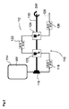
図2は、本発明の第1実施例による低温エンジンシステム110を示す。低温エンジンシステム110の熱力学的動力サイクル112は、断熱された貯蔵タンク114からの加圧された低温作動流体WF(例えば液体窒素)の供給を伴う。これは、タンク114内又は外部に取り付けられた低温ポンプ116を用いて、或いは、例えばヒータ回路を用いたタンク加圧によって実現される。液体窒素は、間接的な熱伝達のために第1熱交換器118に供給され、そこで液体窒素は蒸発して窒素ガスとなり、且つ、第1膨張器120で膨張させられる前に加熱される。膨張はほぼ断熱的であるため、窒素ガスの温度は低下する。それ故に、冷熱は各膨張段階の前後で収集される。第1の膨張の後には更なる熱交換器及び膨張を伴う任意の数の後続の段階が続く。図2に示す実施例は、第2熱交換器122及び第2膨張器124を含む。また、作動流体すなわち窒素ガスは、通気口128を介した大気への放出に先立ち、最後の膨張の後に更なる間接的な排熱交換器126を通過する。各段階における膨張器は、駆動軸130の形で図示される駆動手段を通じて動力を発生させるレシプロ型又はタービン型である。駆動軸130を介した機械力の出力は、詳細を後述する冷凍システムのような他の装置又はシステムに動力を供給するために用いられる。
FIG. 2 shows a
本書では駆動手段130は駆動軸として記載されるが、別の機械的な駆動手段が使用され得ることを当業者は理解する。さらに、液圧的若しくは電気的なポンプ若しくはモータ及び他の非機械的な駆動手段も使用され得る。バッテリのような中間の貯蔵手段も提供され得る。また、各膨張器が個別の駆動手段若しくは駆動軸に結合されてもよく、その場合、それら駆動軸は、例えば電気的結合によって互いに結合されてもよい。 Although the drive means 130 is described herein as a drive shaft, those skilled in the art will appreciate that other mechanical drive means may be used. In addition, hydraulic or electrical pumps or motors and other non-mechanical drive means may be used. An intermediate storage means such as a battery may also be provided. Also, each inflator may be coupled to individual drive means or drive shafts, in which case the drive shafts may be coupled together, for example, by electrical coupling.
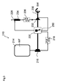
図3は、本発明の第2実施例による低温エンジンシステム210を示す。低温エンジンシステム210は、図2を参照して上述したように、タンク214、第1ポンプ216、第1熱交換器218、第1膨張器220、及び通気口228を含む。しかし、この実施例では、第2ポンプ232及び導入器250を用いて第1膨張器220に導入される(グリコール、水、冷媒、又は空気のような)熱伝達流体を用いて窒素に熱を伝達するために直接接触熱伝達が用いられる。それ故に、窒素は第1膨張器220内で熱伝達流体によって加熱され且つ蒸発させられ得る。膨張後、サイクロン分離器又は他の相分離器234によって熱伝達流体は窒素から分離され、窒素ガスは通気口228を通じて大気中に放出される。窒素から分離されると、熱伝達流体は再熱器236を通過させられ、且つ、再利用のために第2ポンプ232によって第1膨張器220に戻される。
FIG. 3 shows a
図3に示す実施例では、第1膨張器220からの機械力を出力する駆動軸230によって第2ポンプ232が駆動される。しかし、他の任意の都合良く配置された動力源が同様に使用されてもよい。膨張器220はこの場合もやはりレシプロ型又はタービン型であり、駆動軸230を通じて動力出力を発生させる複数の段階又は単一の段階で構成される。或いは、各膨張器は、自身の個別の駆動軸を介して機械仕事を出力してもよく、その場合、それら駆動軸は例えば電気的結合によって互いに結合される。
In the embodiment shown in FIG. 3, the
図2及び図3に示すように、膨張段階からの駆動軸による作業出力は、第1ポンプを駆動するために用いられる。図5〜図8に示す本発明に係るシステムの実施例では、膨張によって生成される機械力及び駆動軸による出力は、冷凍コンパートメントを冷却するための冷凍システムを駆動するために用いられる。冷凍システムは、蒸気圧縮型又は空気循環型のような、軸動力を利用できる任意の公知の構成である。 As shown in FIGS. 2 and 3, the work output from the drive shaft from the expansion stage is used to drive the first pump. In the embodiment of the system according to the invention shown in FIGS. 5 to 8, the mechanical force generated by the expansion and the output by the drive shaft are used to drive a refrigeration system for cooling the refrigeration compartment. The refrigeration system is any known configuration that can utilize shaft power, such as a vapor compression type or an air circulation type.
図4は、駆動軸330を介して冷凍システム360に機械的に結合される、図2に示すシステムのような低温エンジンシステム310を含むシステム300を示す。冷凍システム360は、冷凍コンパートメントから空気を移動させるための第1導管366、コンプレッサ368、冷凍器熱交換器370、膨張器372、及び、冷凍コンパートメントに冷気を戻すための第2導管374を含む空気循環を含む。図4は、駆動軸330が冷凍システム360のコンプレッサ368を駆動することを示す。冷凍システムの膨張器372は駆動軸330の駆動をアシストする。
FIG. 4 shows a
また、低温エンジンシステムと冷凍システムとの間で、機械的結合ばかりでなく、熱的結合を実現することが有利である。図5〜図8は、この利点を実現する本発明の実施例を示す。これらの実施例では、低温エンジンシステムにおける熱交換器は、適切な配管又は他のインタフェース手段を通じ、熱交換システム90における熱交換器に結合される。この目的は、膨張の準備が整った低温エンジンシステムにおける低温流体を温めるためにコンパートメント64からの熱を捕集することにある。また、熱は、大気(周囲の熱)によってもたらされてもよく、例えばICエンジン等の他の任意のソースからもたらされてもよい。このアプローチの他の利点は、冷凍システムからの排熱を増進し、それによってそのシステムの冷凍性能を改善することにある。組み合わされた熱交換器/放熱器における環境での熱伝達に対して付加的であることはこの熱伝達にとって有益となり得る。
It is also advantageous to realize not only mechanical coupling but also thermal coupling between the low temperature engine system and the refrigeration system. 5-8 illustrate an embodiment of the present invention that achieves this advantage. In these embodiments, the heat exchanger in the cryogenic engine system is coupled to the heat exchanger in the
図5は、図4を参照して説明したような空気循環冷凍システムに結合された2段階の熱力学的動力サイクルを有する(図2を参照して上述したシステムのような)低温エンジンシステム410を含むシステム400を示す。低温エンジンシステムにおける第2熱交換器422及び排熱交換器426は、冷凍システムの高温側にある熱交換器470に熱的に結合される。これは付加的であってもよく、或いは、冷凍システムにおける大気との熱交換を置き換えるために用いられてもよい。第1段階の熱交換器418(又は気化器)は、戻り空気流474(すなわち冷凍コンパートメントに戻される冷気)に結合され、冷コンパートメントに戻る前に寒剤によって戻り空気を更に冷却できるようにする。低温流体が液体空気の場合、冷排気を直接そのコンパートメントに放出することも望ましいこととなり得る。前述のように、低温エンジンシステム410の第1ポンプ416、及び、冷凍システム460のコンプレッサ468は全て、低温エンジンシステム410の膨張器によってもたらされる機械仕事を出力する駆動軸430によって駆動される。冷凍システムの膨張器472は駆動軸430の駆動をアシストする。
FIG. 5 shows a cryogenic engine system 410 (such as the system described above with reference to FIG. 2) having a two-stage thermodynamic power cycle coupled to an air circulation refrigeration system as described with reference to FIG. A
図6は、図5のシステムと同様であるが、図3に示すシステムのようなシステム510で置き換えられた低温エンジンシステムを有するシステム500を示す。この構成では、第1膨張器520での膨張中に低温エンジンシステム510における窒素を加熱するために熱交換流体(HEF)が用いられ、有益には、熱交換流体(HEF)の再加熱は冷凍システムの空気循環の高温側からの熱を用いる。導入器550は、HEFが膨張器520に導入されるようにする。これは、窒素膨張において周囲温度より高い温度を可能とし、低温エンジンシステム510の動力サイクルの作業出力を増大させる。
FIG. 6 shows a
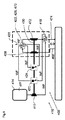
図7は、図2を参照して上述したシステムのような低温エンジンシステム610が蒸気圧縮冷凍システム660と結合される別の実施例を示す。蒸気圧縮冷凍システム660は、冷凍コンパートメント64から空気/大気を移動させるための第1導管666、コンプレッサ668、凝縮器678、膨張弁680、蒸発器682、冷凍コンパートメント64に冷気を戻すための第2導管674、冷凍コンパートメント64から第1及び/又は第2導管を通じて冷却のために空気を循環させるためのファン684を含む。第2熱交換器622及び排熱交換器626は、冷凍システム660の凝縮器678に熱的に結合される。第1段階の熱交換器618と蒸発器682は冷凍コンパートメント64からの冷気と順次的に熱を交換するように配置される。中間熱伝達流体循環システム690は、冷凍システム660の構成要素間で用いられ、且つ、熱伝達流体Fを含む。前述のように、低温エンジンサイクルの第1ポンプ616、及び、冷凍システムのコンプレッサ668は、低温エンジンシステム610の膨張器によってもたらされる機械仕事を出力する駆動軸630によって駆動される。冷却コイルにわたって空気流を送るファン684も駆動軸630によって動力が供給される。
FIG. 7 illustrates another embodiment in which a
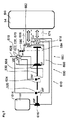
図8は、前述のように熱交換流体(HEF)が低温エンジン装置で用いられる一方で熱伝達流体Fが冷凍回路で用いられるところの更に別の構成を示す。より詳細には、作動流体WFは、膨張器720に導入されるのに先だって膨張させられるように、第1熱交換器718を通過させられる。熱交換流体HEFは個別の回路内に提供される。個別の回路は、HEFを膨張器720に導入するための導入器750と、相分離器734とを含む。相分離器734は、WFからHEFを分離するためのものであり、また、使用済みの作動流体が排気管728を介して大気中に放出されるように、且つ、再利用のためにHEFが膨張器720に送り返される前に再加熱されるところの熱交換器凝縮器722、726、770、778を介してHEFが再循環させられるようにするためのものである。また、熱交換器722は、冷凍システム回路790における凝縮器熱交換器778の機能を果たす。回路790は、図7を参照して上述したものと同様、好適には低温エンジンシ710の駆動手段730によって駆動されるコンプレッサ776と、循環流体Fを膨張させるための膨張器780と、蒸発器782とを更に含む。膨張させられた流体Fは、コンプレッサ776に戻される前に熱交換用蒸発器782を通過する。本構成は、冷凍コンパートメント64からの空気/大気を移動させ、且つ、コンパートメント64からの大気と流体Fとの間で熱を交換できるようにその大気が膨張器熱交換器782を通過するようにさせ、それによって容器64に大気を戻す前にその大気及び第2導管774を冷却できるようにするための第1導管766を更に含む。第1熱交換器718はその大気の流路内に配置されてもよく、好都合には、熱伝達によってその大気を冷却し或いは更に冷却できるように第2導管774内に配置されてもよい。熱交換器782及び718は、導管766、774の一方、他方、又は両方の中で直列に或いは並列に配置されてもよい。
FIG. 8 shows yet another configuration in which the heat transfer fluid (HEF) is used in the low temperature engine device as described above, while the heat transfer fluid F is used in the refrigeration circuit. More specifically, the working fluid WF is passed through the
上述の構成における熱交換器118、122、126、218、236、318、322、326、370、418、422、426、470、518、570、618、622、626、670、718、782、770が個別に且つ/或いは互いに組み合わされ、低温エンジンと、冷凍システム60及び冷凍コンパートメント64自体の一方、他方、又は両方との間で熱を交換するための熱交換システム90を効果的に形成することが理解されるであろう。これらの熱交換器の1又は複数は、熱伝達仕事を実行するときには熱伝達部材として参照され得る。この明細書内では、直接的な熱交換は低温エンジンと冷凍コンパートメント64内からの大気との間での単一の熱交換器を介した熱の交換を参照し、一方で、間接的な熱交換は中間の熱伝達流体を採用する構成を参照する。
上述の実施例の全てでは、(冷凍システム内の何れかの膨張器によってアシストされた)単一の駆動軸又は複数の駆動軸によって出力される低温エンジンからの軸動力は、冷凍システムにおけるコンプレッサ、ポンプ、及び何れかのファンを駆動するために用いられる。別の実施例では、駆動軸によって出力される軸動力の一部又は全部は補助的な動力源として用いられ、それ故に、例えば、照明用オルタネータを駆動するために用いられ、或いは、制御目的で用いられ、或いは、トラクタに動力を供給するための主な動力源として用いられる。 In all of the above embodiments, the shaft power from the cold engine output by a single drive shaft or multiple drive shafts (assisted by any expander in the refrigeration system) is the compressor in the refrigeration system, Used to drive the pump and any fan. In another embodiment, part or all of the shaft power output by the drive shaft is used as an auxiliary power source, and is therefore used, for example, to drive a lighting alternator or for control purposes. Or used as the main power source for powering the tractor.
本発明のシステムの適用例は、重量物運搬車のための冷凍トレーラ、軽量物運搬車及びバンのための冷凍システム、並びに、船舶輸送で用いられる冷凍コンテナのためのシステムを含む。また、そのシステムは、固定された冷凍コンテナ及び建造物のいくつかのクラスにとっても有益である。前述の適用例の全てでは、用語“冷凍”は、腐りやすい商品の輸送のための標準温度(〜0℃)及び冷凍商品のための標準温度(〜−20℃)を含むがそれらには限定されない任意の周囲保持温度(sub-ambient holding temperature)に適用される。また、特に輸送適用例において取り付けられる空調システムの全てのクラスに関し、この発明の潜在用途が存在する。 Applications of the system of the present invention include refrigeration trailers for heavy goods vehicles, refrigeration systems for light weight goods vehicles and vans, and systems for refrigerated containers used in marine transportation. The system is also beneficial for some classes of fixed refrigerated containers and buildings. In all of the aforementioned applications, the term “frozen” includes, but is not limited to, a standard temperature (˜0 ° C.) for the transport of perishable goods and a standard temperature (˜−20 ° C.) for frozen goods. Applies to any sub-ambient holding temperature that is not. There is also the potential use of this invention, especially for all classes of air conditioning systems installed in transportation applications.
本発明は、本発明の実施例を表す添付図面を参照して典型的な形で説明された。本発明の多くの異なる実施例が存在し、且つ、請求項で定められるような発明の範囲内にそれらの実施例の全てが含まれることが理解されるであろう。 The invention has been described in an exemplary manner with reference to the accompanying drawings, which represent embodiments of the invention. It will be appreciated that there are many different embodiments of the invention and that all are included within the scope of the invention as defined in the claims.
Claims (17)
熱交換システム(90)を含む冷凍システム(660);を含むシステムであって、
前記低温エンジンシステム(610、710)と前記冷凍システム(660)は前記熱交換システム(90)を介して互いに熱的に結合され、
前記低温エンジンシステム(610、710)における前記作動流体(WF)及び/又は前記熱交換流体(HEF)が前記冷凍システム(660)から熱を除去するヒートシンクの機能を果たし、且つ、前記冷凍システム(660)によって生成される熱が前記低温エンジンシステム(610、710)における作動流体(WF)を膨張させるために用いられるようにし、
当該システムは、前記熱交換システム(90)に熱的に接続される冷凍コンパートメント(64)を含み、
前記低温エンジンシステム(610、710)は、前記冷凍コンパートメント(64)から熱を除去するための直接的且つ間接的なヒートシンクであり、且つ、
前記熱交換システム(90)は:
前記低温エンジンシステム(610、710)からの作動流体(WF)と直接的に熱的に接触し且つ前記冷凍コンパートメント(64)と直接的に熱的に接触する第1熱伝達部材(618、718)と;
前記低温エンジンシステム(610、710)における膨張させられた作動流体(WF)及び/又は前記熱交換流体(HEF)と直接的に熱的に接触する第2熱伝達部材(622、626、670、678、722、726、770、778)と;
前記冷凍コンパートメント(64)の内部と直接的に熱的に接触する第3熱伝達部材(682、782)と;
前記第2熱伝達部材(622、626、678、722、726、778)及び第3熱伝達部材(682、782)の双方と熱的に接触する中間熱伝達流体循環システム(690、790)と;を有する、
システム。 A cryogenic engine system (610, 710) utilizing a working fluid (WF) and a heat exchange fluid (HEF); and a refrigeration system (660) comprising a heat exchange system (90);
The cryogenic engine system (610, 710) and the refrigeration system (660) are thermally coupled to each other via the heat exchange system (90),
The working fluid (WF) and / or the heat exchange fluid (HEF) in the cryogenic engine system (610, 710) serve as a heat sink that removes heat from the refrigeration system (660), and the refrigeration system ( 660) is used to expand the working fluid (WF) in the cold engine system (610, 710);
The system includes a refrigeration compartment (64) that is thermally connected to the heat exchange system (90);
The cryogenic engine system (610, 710) is a direct and indirect heat sink for removing heat from the refrigeration compartment (64); and
The heat exchange system (90) is:
First heat transfer members (618, 718) in direct thermal contact with the working fluid (WF) from the cryogenic engine system (610, 710) and in direct thermal contact with the refrigeration compartment (64). )When;
A second heat transfer member (622, 626, 670) in direct thermal contact with the expanded working fluid (WF) and / or the heat exchange fluid (HEF) in the cryogenic engine system (610, 710); 678, 722, 726, 770, 778);
A third heat transfer member (682, 782) in direct thermal contact with the interior of the refrigeration compartment (64);
An intermediate heat transfer fluid circulation system (690, 790) in thermal contact with both the second heat transfer member (622, 626, 678, 722, 726, 778) and the third heat transfer member (682, 782); Having
system.
請求項1に記載のシステム。 The refrigeration system (660) includes a vapor compression cycle.
The system of claim 1.
請求項1又は2に記載のシステム。 The intermediate heat transfer fluid circulation system (690, 790) includes a heat transfer fluid (F) and a compressor (676, 776) for compressing the heat transfer fluid (F) in the system.
The system according to claim 1 or 2.
前記コンプレッサ(676、776)は前記駆動手段(630、730)によって駆動される、
請求項3に記載のシステム。 The low temperature engine system (610, 710) includes driving means (630, 730),
The compressor (676, 776) is driven by the driving means (630, 730).
The system according to claim 3.
請求項1乃至4の何れか一項に記載のシステム。 The first heat transfer member (618) and / or the third heat transfer member (682) are configured to exchange heat with the interior (64i) of the refrigeration compartment (64),
The system according to any one of claims 1 to 4.
請求項1乃至5の何れか一項に記載のシステム。 A first conduit (666) for moving the atmosphere from the interior (64i) of the refrigeration compartment (64) and directing the atmosphere over the third heat transfer member (682); and of the refrigeration compartment (64) A second conduit (674) for returning the atmosphere to the interior (64i),
The system according to any one of claims 1 to 5.
請求項6に記載のシステム。 A fan (684, 784) for circulating the atmosphere from the refrigeration compartment (64) through the first conduit (666, 766) and / or the second conduit (674, 774),
The system according to claim 6.
前記第2熱伝達部材(622、722)によって形成される凝縮器(678、778);
膨張器(680、780);及び
前記第3熱伝達部材(682、782)によって形成される蒸発器;
を更に含む、
請求項3乃至6の何れか一項に記載のシステム。 The intermediate heat transfer fluid circulation system (690, 790) is:
A condenser (678, 778) formed by the second heat transfer member (622, 722);
An expander (680, 780); and an evaporator formed by the third heat transfer member (682, 782);
Further including
The system according to any one of claims 3 to 6.
請求項1乃至8の何れか一項に記載のシステム。 Working fluid (from the vent or exhaust pipe to the refrigeration compartment, extending between the vent or exhaust pipe (128, 228) in the cryogenic engine system (110) and the refrigeration compartment (64) of the refrigeration system ( Further comprising a second transmission means for transferring (WF).
The system according to any one of claims 1 to 8.
前記冷凍コンパートメント(64)から空気を移動させるための第1導管(366、466、566);
コンプレッサ(368、468、568);
膨張に先だって前記冷凍システムにおける空気を冷却するための冷凍器熱交換器(370、470、570);
膨張器(372、472、572);及び
膨張させられた冷気を前記冷凍コンパートメント(64)に戻すための第2導管(374、474、574);
を含む、
請求項1に記載のシステム。 The refrigeration system is air circulating, and
A first conduit (366, 466, 566) for moving air from the refrigeration compartment (64);
Compressor (368, 468, 568);
Refrigerator heat exchangers (370, 470, 570) for cooling air in the refrigeration system prior to expansion;
An inflator (372, 472, 572); and a second conduit (374, 474, 574) for returning the inflated cold air to the refrigeration compartment (64);
including,
The system of claim 1.
請求項10に記載のシステム。 The compressor of the refrigeration system is driven by driving means (330, 430, 530) of the low temperature engine system (310, 410, 510).
The system according to claim 10.
請求項10又は11に記載のシステム。 At least one heat exchanger (118, 122, 126, 218, 222, 226, 318, 322, 326) in the cryogenic engine system (110) is at least one heat exchanger (370, 470, 418, 570, 518, 670, 618),
The system according to claim 10 or 11.
請求項12に記載のシステム。 The second heat transfer members (422 , 622, 626, 670, 678, 722, 726, 770, 778 ) in the low temperature engine system (110) are connected to the refrigerator heat exchangers ( 370, 470 , 418, 570, 518, 670, 618 ),
The system of claim 12 .
作動流体(WF)を蓄えるためのタンク(114、214、314、414、514、614、714);
駆動手段(130、230、330、430、530、630、730);
前記駆動手段(130、230、330、430、530、630、730)に結合され、前記タンク(114、214、314、414、514、614、714)と流体的に連通し、且つ、前記駆動手段(130、230、330、430、530、630、730)を介して機械仕事を出力するように前記作動流体(WF)を膨張させるように構成される第1膨張器(120、220、320、330、420、520、620、720);及び
前記タンク(114、214、314、414、514、614、714)と前記第1膨張器(120、220、320、420、520、620、720)との間で流体的に連通し、且つ、前記作動流体(WF)が前記第1膨張器(120、220、320、420、520、620、720)に供給される前に前記作動流体(WF)に熱を伝達するように構成される第1熱交換器(118、218、318、418、518、618、718);を含み、
前記熱交換流体(HEF)を前記第1膨張器(220、520)に導入するための導入器(250、550)を更に含み、
前記第1膨張器(220、520)は、前記作動流体(WF)と前記熱交換流体(HEF)とを混合するように構成される、
請求項1乃至13の何れか一項に記載のシステム。 The cryogenic engine system (110) is:
Tanks (114, 214, 314, 414, 514, 614, 714) for storing working fluid (WF);
Driving means (130, 230, 330, 430, 530, 630, 730);
Coupled to the drive means (130, 230, 330, 430, 530, 630, 730), in fluid communication with the tank (114, 214, 314, 414, 514, 614, 714) and the drive A first inflator (120, 220, 320) configured to inflate the working fluid (WF) to output mechanical work via means (130, 230, 330, 430, 530, 630, 730). , 330, 420, 520, 620, 720); and the tank (114, 214, 314, 414, 514, 614, 714) and the first inflator (120, 220, 320, 420, 520, 620, 720). And the working fluid (WF) is in fluid communication with the first inflator (120, 220, 320, 420, 520, 620, 7). 20) a first heat exchanger (118, 218, 318, 418, 518, 618, 718) configured to transfer heat to the working fluid (WF) before being supplied to 20);
An introducer (250, 550) for introducing the heat exchange fluid (HEF) into the first expander (220, 520);
The first expander (220, 520) is configured to mix the working fluid (WF) and the heat exchange fluid (HEF).
The system according to any one of claims 1 to 13.
膨張後に前記熱交換流体(HEF)から前記作動流体(WF)を分離するために前記第1膨張器(220、520)と流体的に連通する相分離器(234、534);
前記熱交換流体(HEF)を再加熱するための再熱器(236、570);及び
前記熱交換流体(HEF)を前記第1膨張器(220、520)に戻すための第2ポンプ(232、532);
を含む、
請求項14に記載のシステム。 The cryogenic engine system (210, 510) is:
Phase separators (234, 534) in fluid communication with the first expander (220, 520) to separate the working fluid (WF) from the heat exchange fluid (HEF) after expansion;
A reheater (236, 570) for reheating the heat exchange fluid (HEF); and a second pump (232) for returning the heat exchange fluid (HEF) to the first expander (220, 520). 532);
including,
The system according to claim 14.
請求項15に記載のシステム。 The second pump (232, 532) is driven by the driving means (230, 530),
The system according to claim 15.
請求項1乃至16の何れか一項に記載のシステム。 The working fluid (WF) includes at least one of liquid nitrogen, liquid air, liquefied natural gas, carbon dioxide, oxygen, argon, compressed air, and compressed natural gas.
The system according to any one of claims 1 to 16.
Applications Claiming Priority (3)
| Application Number | Priority Date | Filing Date | Title |
|---|---|---|---|
| GB1220788.2A GB2508017A (en) | 2012-11-19 | 2012-11-19 | A cryogenic engine driven refrigeration system |
| GB1220788.2 | 2012-11-19 | ||
| PCT/GB2013/053056 WO2014076508A1 (en) | 2012-11-19 | 2013-11-19 | Improvements in refrigeration |
Publications (3)
| Publication Number | Publication Date |
|---|---|
| JP2016501357A JP2016501357A (en) | 2016-01-18 |
| JP2016501357A5 JP2016501357A5 (en) | 2017-01-05 |
| JP6368314B2 true JP6368314B2 (en) | 2018-08-01 |
Family
ID=47521383
Family Applications (1)
| Application Number | Title | Priority Date | Filing Date |
|---|---|---|---|
| JP2015542361A Active JP6368314B2 (en) | 2012-11-19 | 2013-11-19 | Improved refrigeration |
Country Status (15)
| Country | Link |
|---|---|
| US (1) | US10336159B2 (en) |
| EP (1) | EP2920526B1 (en) |
| JP (1) | JP6368314B2 (en) |
| KR (1) | KR102148680B1 (en) |
| CN (1) | CN104884877B (en) |
| DK (1) | DK2920526T3 (en) |
| ES (1) | ES2947219T3 (en) |
| FI (1) | FI2920526T3 (en) |
| GB (1) | GB2508017A (en) |
| HK (1) | HK1213973A1 (en) |
| HU (1) | HUE062128T2 (en) |
| MY (1) | MY181162A (en) |
| PL (1) | PL2920526T3 (en) |
| PT (1) | PT2920526T (en) |
| WO (1) | WO2014076508A1 (en) |
Families Citing this family (5)
| Publication number | Priority date | Publication date | Assignee | Title |
|---|---|---|---|---|
| GB2542604A (en) * | 2015-09-25 | 2017-03-29 | Linde Ag | Refrigeration apparatus |
| GB201601878D0 (en) * | 2016-02-02 | 2016-03-16 | Highview Entpr Ltd | Improvements in power recovery |
| US10941713B2 (en) | 2016-05-27 | 2021-03-09 | Carrier Corporation | Multi-fuel transport refrigeration unit |
| EP4073357A4 (en) * | 2019-12-13 | 2024-01-24 | Univ Nanyang Tech | Cryogenic energy system for cooling and powering an indoor environment |
| WO2023249815A1 (en) * | 2022-06-19 | 2023-12-28 | Yiding Cao | Air-water thermal power plants |
Family Cites Families (27)
| Publication number | Priority date | Publication date | Assignee | Title |
|---|---|---|---|---|
| GB1038575A (en) * | 1964-05-04 | 1966-08-10 | Fleur Corp | Improvements in or relating to refrigeration systems |
| US3451342A (en) * | 1965-10-24 | 1969-06-24 | Everett H Schwartzman | Cryogenic engine system and method |
| GB1298558A (en) | 1969-10-27 | 1972-12-06 | Shipowners Cargo Res Assoc | Fluidic control apparatus |
| US3842333A (en) * | 1970-12-03 | 1974-10-15 | H Boese | Non-pollution motor units |
| US4311917A (en) * | 1980-03-31 | 1982-01-19 | Thomas R. Hencey, Jr. | Non-pollution motor |
| US5311927A (en) | 1992-11-27 | 1994-05-17 | Thermo King Corporation | Air conditioning and refrigeration apparatus utilizing a cryogen |
| US5267443A (en) | 1992-11-27 | 1993-12-07 | Thermo King Corporation | Air conditioning and refrigeration methods and apparatus utilizing a cryogen |
| CA2178221C (en) * | 1994-10-05 | 2002-05-28 | Isao Nikai | Cold air supply unit |
| JPH1019402A (en) * | 1996-07-04 | 1998-01-23 | Kobe Steel Ltd | Low temperature refrigeration system by gas turbine |
| GB2355511A (en) * | 1999-07-15 | 2001-04-25 | Air Prod & Chem | Freezing products |
| US6345509B1 (en) | 2000-01-21 | 2002-02-12 | Ukram Industries | Refrigeration of a food transport vehicle utilizing liquid nitrogen |
| US6349787B1 (en) * | 2000-05-08 | 2002-02-26 | Farouk Dakhil | Vehicle having a turbine engine and a flywheel powered by liquid nitrogen |
| GB2371107A (en) * | 2001-01-15 | 2002-07-17 | Air Prod & Chem | Freezing products |
| US6751966B2 (en) * | 2001-05-25 | 2004-06-22 | Thermo King Corporation | Hybrid temperature control system |
| US20060000228A1 (en) * | 2004-06-30 | 2006-01-05 | Fisher Craig B | Auxiliary air-conditioning apparatuses and methods for vehicles |
| US7080521B2 (en) * | 2004-08-31 | 2006-07-25 | Thermo King Corporation | Mobile refrigeration system and control |
| GB0506006D0 (en) * | 2005-03-23 | 2005-04-27 | Howes Jonathan S | Apparatus for use as a heat pump |
| GB0513463D0 (en) * | 2005-07-01 | 2005-08-10 | Highview Entpr Ltd | Injection apparatus for cryogenic engines |
| US7401475B2 (en) * | 2005-08-24 | 2008-07-22 | Purdue Research Foundation | Thermodynamic systems operating with near-isothermal compression and expansion cycles |
| US20070163261A1 (en) * | 2005-11-08 | 2007-07-19 | Mev Technology, Inc. | Dual thermodynamic cycle cryogenically fueled systems |
| DE102006016558A1 (en) * | 2006-04-07 | 2007-10-11 | Air Liquide Deutschland Gmbh | Method for monitoring the gas-tightness of a cooling system of a refrigerated vehicle and for operating the same and cooling system for a refrigerated vehicle and refrigerated vehicle |
| DE102006016557A1 (en) | 2006-04-07 | 2007-10-11 | Air Liquide Deutschland Gmbh | Refrigerated vehicle with external cooling module and cooling method |
| CN100565039C (en) * | 2007-04-03 | 2009-12-02 | 中国科学院理化技术研究所 | Be used for the coupling device between the refrigeration machine of thermoacoustic engine and driving thereof |
| US20080314059A1 (en) * | 2007-06-20 | 2008-12-25 | Thermo King Corporation | Double clutch drive system |
| FR2945336B1 (en) | 2009-05-07 | 2013-05-03 | Air Liquide | METHOD AND APPARATUS FOR REGULAR TRANSPORT USING INDIRECT INJECTION OF A CRYOGENIC LIQUID AND CONTROLLING THE EXCHANGER ENHANCING PHENOMENA |
| JP5310289B2 (en) * | 2009-06-17 | 2013-10-09 | アイシン精機株式会社 | Air conditioner |
| WO2011126581A2 (en) | 2010-04-05 | 2011-10-13 | Ukram Industries, Ltd. | System and method for delivering cryogenic fluid to a spray head used to cool an enclosed space |
-
2012
- 2012-11-19 GB GB1220788.2A patent/GB2508017A/en not_active Withdrawn
-
2013
- 2013-11-19 FI FIEP13796132.2T patent/FI2920526T3/en active
- 2013-11-19 JP JP2015542361A patent/JP6368314B2/en active Active
- 2013-11-19 PT PT137961322T patent/PT2920526T/en unknown
- 2013-11-19 CN CN201380060297.4A patent/CN104884877B/en active Active
- 2013-11-19 HU HUE13796132A patent/HUE062128T2/en unknown
- 2013-11-19 MY MYPI2015701591A patent/MY181162A/en unknown
- 2013-11-19 DK DK13796132.2T patent/DK2920526T3/en active
- 2013-11-19 US US14/443,760 patent/US10336159B2/en active Active
- 2013-11-19 EP EP13796132.2A patent/EP2920526B1/en active Active
- 2013-11-19 KR KR1020157016454A patent/KR102148680B1/en active IP Right Grant
- 2013-11-19 WO PCT/GB2013/053056 patent/WO2014076508A1/en active Application Filing
- 2013-11-19 PL PL13796132.2T patent/PL2920526T3/en unknown
- 2013-11-19 ES ES13796132T patent/ES2947219T3/en active Active
-
2016
- 2016-02-23 HK HK16101997.3A patent/HK1213973A1/en unknown
Also Published As
| Publication number | Publication date |
|---|---|
| ES2947219T3 (en) | 2023-08-03 |
| GB201220788D0 (en) | 2013-01-02 |
| FI2920526T3 (en) | 2023-06-14 |
| CN104884877B (en) | 2017-03-08 |
| HK1213973A1 (en) | 2016-07-15 |
| PT2920526T (en) | 2023-06-19 |
| DK2920526T3 (en) | 2023-06-19 |
| JP2016501357A (en) | 2016-01-18 |
| KR20150094647A (en) | 2015-08-19 |
| US20150291007A1 (en) | 2015-10-15 |
| MY181162A (en) | 2020-12-20 |
| EP2920526A1 (en) | 2015-09-23 |
| US10336159B2 (en) | 2019-07-02 |
| HUE062128T2 (en) | 2023-09-28 |
| WO2014076508A1 (en) | 2014-05-22 |
| CN104884877A (en) | 2015-09-02 |
| PL2920526T3 (en) | 2023-08-14 |
| KR102148680B1 (en) | 2020-08-27 |
| GB2508017A (en) | 2014-05-21 |
| EP2920526B1 (en) | 2023-03-15 |
Similar Documents
| Publication | Publication Date | Title |
|---|---|---|
| CN107428223B (en) | Transport refrigeration unit with multiple compressors | |
| JP6368314B2 (en) | Improved refrigeration | |
| US8904818B2 (en) | Refrigerator | |
| EP2796810A1 (en) | Cooling device | |
| CN105531130A (en) | Air conditioning system utilizing thermal capacity from expansion of compressed fluid | |
| EP3218655B1 (en) | Refrigeration system | |
| KR20130031843A (en) | Boil-off gas reliquefaction device | |
| US20150292784A1 (en) | Organic rankine cycle augmented power supply system for mobile refrigeration units | |
| JP2016501357A5 (en) | ||
| EP2921761B1 (en) | Tank internal pressure suppression device | |
| CN106457973A (en) | Dual circuit transportation refrigeration system | |
| US6519946B2 (en) | Cogeneration system using waste-heat gas generated in micro gas turbine | |
| JP2005090636A (en) | Transportation system for liquefied hydrogen | |
| KR101843745B1 (en) | Cooling and heating system for bus vehicle | |
| JP4698526B2 (en) | Refrigeration apparatus and LNG refrigeration vehicle equipped with the same | |
| KR20160004169A (en) | Cargo box or container with self electricity generate refrigeration system | |
| JP2006200841A (en) | Portable refrigeration unit and its using method | |
| CN205536641U (en) | Realize heat endless thermodynamic cycle system through environment working medium | |
| CN105783300A (en) | Thermodynamics circulation system achieving heat circulation through environment working media and application | |
| KR101563856B1 (en) | System for supplying fuel gas in ships | |
| Saeed et al. | CO2 refrigeration system design and optimization for LNG driven cruise ships | |
| WO2016020706A1 (en) | Thermodynamic system for powering an engine using an external thermal energy source | |
| WO2021123484A1 (en) | Method and equipment for refrigeration | |
| KR20240048997A (en) | A refrigeration vehicle using dual DC compressor | |
| BR102020018428A2 (en) | System for reusing the thermal energy of the exhaust gases of a vehicle for cooling or air conditioning |
Legal Events
| Date | Code | Title | Description |
|---|---|---|---|
| A521 | Request for written amendment filed |
Free format text: JAPANESE INTERMEDIATE CODE: A523 Effective date: 20161114 |
|
| A621 | Written request for application examination |
Free format text: JAPANESE INTERMEDIATE CODE: A621 Effective date: 20161114 |
|
| A977 | Report on retrieval |
Free format text: JAPANESE INTERMEDIATE CODE: A971007 Effective date: 20171122 |
|
| A131 | Notification of reasons for refusal |
Free format text: JAPANESE INTERMEDIATE CODE: A131 Effective date: 20171128 |
|
| A521 | Request for written amendment filed |
Free format text: JAPANESE INTERMEDIATE CODE: A523 Effective date: 20180222 |
|
| TRDD | Decision of grant or rejection written | ||
| A01 | Written decision to grant a patent or to grant a registration (utility model) |
Free format text: JAPANESE INTERMEDIATE CODE: A01 Effective date: 20180612 |
|
| A61 | First payment of annual fees (during grant procedure) |
Free format text: JAPANESE INTERMEDIATE CODE: A61 Effective date: 20180706 |
|
| R150 | Certificate of patent or registration of utility model |
Ref document number: 6368314 Country of ref document: JP Free format text: JAPANESE INTERMEDIATE CODE: R150 |
|
| R250 | Receipt of annual fees |
Free format text: JAPANESE INTERMEDIATE CODE: R250 |
|
| R250 | Receipt of annual fees |
Free format text: JAPANESE INTERMEDIATE CODE: R250 |
|
| R250 | Receipt of annual fees |
Free format text: JAPANESE INTERMEDIATE CODE: R250 |