JP6357013B2 - Flush tank with flared inlet insert and method for introducing flow into the flash tank - Google Patents
Flush tank with flared inlet insert and method for introducing flow into the flash tank Download PDFInfo
- Publication number
- JP6357013B2 JP6357013B2 JP2014107648A JP2014107648A JP6357013B2 JP 6357013 B2 JP6357013 B2 JP 6357013B2 JP 2014107648 A JP2014107648 A JP 2014107648A JP 2014107648 A JP2014107648 A JP 2014107648A JP 6357013 B2 JP6357013 B2 JP 6357013B2
- Authority
- JP
- Japan
- Prior art keywords
- inlet tube
- flash tank
- outlet
- section
- insertion inlet
- Prior art date
- Legal status (The legal status is an assumption and is not a legal conclusion. Google has not performed a legal analysis and makes no representation as to the accuracy of the status listed.)
- Active
Links
Images


Classifications
-
- D—TEXTILES; PAPER
- D21—PAPER-MAKING; PRODUCTION OF CELLULOSE
- D21C—PRODUCTION OF CELLULOSE BY REMOVING NON-CELLULOSE SUBSTANCES FROM CELLULOSE-CONTAINING MATERIALS; REGENERATION OF PULPING LIQUORS; APPARATUS THEREFOR
- D21C11/00—Regeneration of pulp liquors or effluent waste waters
-
- B—PERFORMING OPERATIONS; TRANSPORTING
- B01—PHYSICAL OR CHEMICAL PROCESSES OR APPARATUS IN GENERAL
- B01D—SEPARATION
- B01D19/00—Degasification of liquids
- B01D19/0036—Flash degasification
-
- D—TEXTILES; PAPER
- D21—PAPER-MAKING; PRODUCTION OF CELLULOSE
- D21C—PRODUCTION OF CELLULOSE BY REMOVING NON-CELLULOSE SUBSTANCES FROM CELLULOSE-CONTAINING MATERIALS; REGENERATION OF PULPING LIQUORS; APPARATUS THEREFOR
- D21C11/00—Regeneration of pulp liquors or effluent waste waters
- D21C11/04—Regeneration of pulp liquors or effluent waste waters of alkali lye
-
- D—TEXTILES; PAPER
- D21—PAPER-MAKING; PRODUCTION OF CELLULOSE
- D21C—PRODUCTION OF CELLULOSE BY REMOVING NON-CELLULOSE SUBSTANCES FROM CELLULOSE-CONTAINING MATERIALS; REGENERATION OF PULPING LIQUORS; APPARATUS THEREFOR
- D21C11/00—Regeneration of pulp liquors or effluent waste waters
- D21C11/06—Treatment of pulp gases; Recovery of the heat content of the gases; Treatment of gases arising from various sources in pulp and paper mills; Regeneration of gaseous SO2, e.g. arising from liquors containing sulfur compounds
-
- D—TEXTILES; PAPER
- D21—PAPER-MAKING; PRODUCTION OF CELLULOSE
- D21C—PRODUCTION OF CELLULOSE BY REMOVING NON-CELLULOSE SUBSTANCES FROM CELLULOSE-CONTAINING MATERIALS; REGENERATION OF PULPING LIQUORS; APPARATUS THEREFOR
- D21C11/00—Regeneration of pulp liquors or effluent waste waters
- D21C11/10—Concentrating spent liquor by evaporation
Landscapes
- Chemical & Material Sciences (AREA)
- Chemical Kinetics & Catalysis (AREA)
- Paper (AREA)
- Vaporization, Distillation, Condensation, Sublimation, And Cold Traps (AREA)
Description
本開示は、加圧反応槽から抽出された流体をフラッシュすることに一般的に関連し、パルプ化又はバイオマス処理システムにおける加圧反応槽からの黒液をフラッシュするためのフラッシュタンクに特に関する。 The present disclosure relates generally to flushing fluid extracted from a pressurized reaction vessel and specifically relates to a flash tank for flushing black liquor from a pressurized reaction vessel in a pulping or biomass processing system.
フラッシュタンクは、スチーム及び凝縮物を含む高圧の流体薬液流をフラッシュするために一般に使用される。フラッシュタンクは、高圧入口ポート、内部チャンバー、上部のスチーム又は気体排出ポート、及び下部の凝縮物又は液体排出ポートを典型的に有する。フラッシュタンクは、加圧された流体流における圧力を安全且つ効率的に減少させ、上記流体流により生じた蒸気からの熱エネルギーの回収を可能にし、上記流体流のうちの凝縮物から化学薬品を捕集する。 A flash tank is commonly used to flush a high pressure fluid chemical stream containing steam and condensate. A flash tank typically has a high pressure inlet port, an internal chamber, an upper steam or gas outlet port, and a lower condensate or liquid outlet port. The flash tank safely and efficiently reduces the pressure in the pressurized fluid stream, enables recovery of thermal energy from the vapor generated by the fluid stream, and removes chemicals from the condensate in the fluid stream. Collect.
フラッシュタンクはケミカルパルプ化システム、例えばクラフト蒸解システムから化学薬品を回収するために使用される。フラッシュタンクは、ケミカルパルプ化システム及びメカニカル−ケミカルパルプ化システムのための他のタイプの蒸解システムにおいても使用される。木材チップ又は他の細砕セルロース繊維有機材料(本明細書では「セルロース材料」と総称する)をパルプ化するために、セルロース材料は薬液、例えば水及び蒸解化学薬品と混合され、加圧処理槽にポンプ輸送される。水酸化ナトリウム、亜硫酸ナトリウム及び他のアルカリ化学薬品は、例えばクラフト蒸解プロセスにおいて、セルロース材料を「蒸解」するために使用される。これらの化学薬品は、セルロース材料内の、リグニン、並びにヘミセルロース化合物及びセルロース化合物を分解し、可溶化させることに貢献する。クラフト蒸解プロセスはセ氏100度(100℃)〜170℃の範囲の温度、及び大気圧か、大気圧より高い圧力か又は実質的に大気圧より高い圧力、例えば5バールゲージ〜15バールゲージを超える圧力で行われる。他の従来の蒸解プロセスにおいて、セルロース材料は、主にヘミセルロース化合物を可溶化させることを目的として酸加水分解を開始するために水又は酸と処理されている。 Flash tanks are used to recover chemicals from chemical pulping systems, such as kraft cooking systems. Flash tanks are also used in other types of cooking systems for chemical and mechanical-chemical pulping systems. In order to pulp wood chips or other comminuted cellulose fiber organic materials (collectively referred to herein as “cellulosic materials”), the cellulosic material is mixed with a chemical solution, such as water and cooking chemicals, and a pressure treatment tank To be pumped. Sodium hydroxide, sodium sulfite and other alkaline chemicals are used to “cook” the cellulosic material, for example, in a kraft cooking process. These chemicals contribute to the degradation and solubilization of lignin as well as hemicellulose compounds and cellulose compounds in the cellulosic material. The kraft cooking process has a temperature in the range of 100 degrees Celsius (100 ° C.) to 170 ° C., and atmospheric pressure, a pressure higher than atmospheric pressure or a pressure substantially higher than atmospheric pressure, for example, exceeding 5 bar gauge to 15 bar gauge Done with pressure. In other conventional cooking processes, the cellulosic material is treated with water or acid to initiate acid hydrolysis primarily for the purpose of solubilizing the hemicellulose compound.
蒸解(反応)槽は、バッチ式槽又は連続流式槽である。蒸解槽は一般に垂直に配向され、1日につき1,000トン又はそれ以上のセルロース材料を処理するために十分な大きさである。連続流式槽において、セルロース材料は連続的に槽に流入、流出し、槽に数分間又は数時間も滞留する。蒸解槽に加えて、従来のパルプ化システムは、他の反応槽(例えば、大気圧、大気圧近く、又は大気圧超で稼働している槽)を、例えば、蒸解槽に先行してセルロース材料を薬液に含浸させるために含むことがある。含浸槽及び蒸解槽中の大量のセルロース材料を考慮すると、大量の黒液がこれらの槽から典型的に抽出される。 The cooking (reaction) tank is a batch tank or a continuous flow tank. The digester is generally vertically oriented and is large enough to process 1,000 tons or more of cellulosic material per day. In a continuous flow tank, the cellulosic material continuously flows into and out of the tank and stays in the tank for several minutes or hours. In addition to digestion tanks, conventional pulping systems can use other reaction tanks (eg, tanks operating at, near, or above atmospheric pressure), eg, cellulosic material prior to the digestion tank. May be included to impregnate the chemical solution. Considering the large amount of cellulosic material in the impregnation and digester, large amounts of black liquor are typically extracted from these vessels.
黒液は、蒸解化学薬品、及び有機化学薬品若しくは有機化合物、例えば、セルロース供給材料から溶解した、加水分解物、残留アルカリ、リグニン、ヘミセルロース及び他の溶解有機物質を含む。黒液はスチーム及び凝縮物を生成するためにフラッシュタンクで典型的にフラッシュされる。蒸解化学薬品及び有機化合物は、フラッシュ後の液体画分に一般に含まれる。フラッシュにより形成されたスチームは、蒸解化学薬品及び有機化合物を一般に含まない。液体画分は、例えば蒸解化学薬品を回収し、再苛性化するために処理される。スチームはパルプ化システムにおいて熱エネルギーとして使用される。 Black liquor contains cooking chemicals and organic chemicals or organic compounds such as hydrolysates, residual alkali, lignin, hemicellulose and other dissolved organic substances dissolved from cellulose feedstock. Black liquor is typically flushed in a flash tank to produce steam and condensate. Cooking chemicals and organic compounds are generally included in the liquid fraction after flushing. The steam formed by flash is generally free of cooking chemicals and organic compounds. The liquid fraction is processed, for example, to recover cooking chemicals and re-causticize. Steam is used as thermal energy in the pulping system.
従来のフラッシュタンクにおいて、黒液はタンクの側壁上の入口ポートに連結された入口パイプを通って通常流入する。他の従来のフラッシュタンクでは、入口ポートは槽の頂部に位置している。入口ポートは、典型的には、フラッシュタンクの側壁において円形又は楕円形の開口である。黒液は入口パイプからフラッシュタンクに典型的に流入する。入口パイプからフラッシュタンクまでの遷移は断続的(abrupt)であり、これがフラッシュタンクに流入する黒液の分断(disruption)及び乱流(turbulence)を引き起こす。 In conventional flash tanks, black liquor normally flows through an inlet pipe connected to an inlet port on the tank sidewall. In other conventional flash tanks, the inlet port is located at the top of the tank. The inlet port is typically a circular or elliptical opening in the side wall of the flash tank. Black liquor typically flows from the inlet pipe into the flash tank. The transition from the inlet pipe to the flash tank is abrupt, which causes disruption and turbulence of the black liquor entering the flash tank.
例示的な実施形態において、フラッシュタンクが発明され、このフラッシュタンクは、
フラッシュタンクの側壁によって形成された内部表面を有する内部チャンバー、
前記チャンバーの上部部分に連結されている蒸気排出ポート、
前記チャンバーの下部部分に連結されている液体排出ポート、
挿入出口を有し、チャンバーの入口ポートに挿入された挿入入口チューブを含み、
前記挿入入口チューブは側壁の内側に延びており、前記挿入出口はフラッシュタンクの中心垂直軸に対して実質的に平行に、且つフラッシュタンクの半径ラインに対して実質的に垂直に配向された伸長した断面形状を有し、それによって挿入出口は側壁に実質的に接している。
In an exemplary embodiment, a flash tank is invented, the flash tank being
An internal chamber having an internal surface formed by the side walls of the flash tank,
A steam exhaust port connected to the upper portion of the chamber;
A liquid discharge port connected to the lower portion of the chamber;
An insertion inlet tube having an insertion outlet and inserted into an inlet port of the chamber;
The insertion inlet tube extends inside the side wall, and the insertion outlet is elongated substantially parallel to the central vertical axis of the flash tank and substantially perpendicular to the radial line of the flash tank. The insertion outlet is substantially in contact with the side wall.
挿入入口チューブは、フラッシュタンクの垂直軸から半径方向に延びているラインに垂直な長手軸を有する。挿入入口チューブアセンブリは、フラッシュタンクの垂直軸及び挿入入口チューブの長手軸に対して垂直に延びている半径ラインに実質的に位置合わせされた挿入出口を有する。挿入入口チューブは、長手軸を中心とする円形の断面を有する円筒状セクション、及び円形セクションと挿入出口との間のフレア状セクションを含み、フレア状セクションは、円筒状セクションの長手軸から、挿入出口に近接するフラッシュタンクの側壁の方へと徐々にオフセットされている。挿入入口チューブの断面積は挿入入口チューブの長さに沿って実質的に均一である。 The insertion inlet tube has a longitudinal axis perpendicular to the line extending radially from the vertical axis of the flash tank. The insertion inlet tube assembly has an insertion outlet substantially aligned with a radial line extending perpendicular to the vertical axis of the flash tank and the longitudinal axis of the insertion inlet tube. The insertion inlet tube includes a cylindrical section having a circular cross section about the longitudinal axis, and a flared section between the circular section and the insertion outlet, the flared section being inserted from the longitudinal axis of the cylindrical section. It is gradually offset towards the side wall of the flash tank close to the outlet. The cross-sectional area of the insertion inlet tube is substantially uniform along the length of the insertion inlet tube.
別の例示的な実施形態において、側壁及び挿入入口ポートを含むフラッシュタンクのための挿入入口チューブアセンブリが発明され、この挿入入口チューブアセンブリは、入口ポートに挿入されて入口ポートに固定されるように構成されたチューブ状セクション、及びチューブ状セクションの挿入出口を含み、
前記挿入入口チューブアセンブリはチャンバーの入口ポートに挿入されており、
前記挿入入口チューブは側壁の内側に延びており、
前記挿入出口はフラッシュタンクの中心垂直軸に対して実質的に平行に、且つフラッシュタンクの半径ラインに対して実施的に垂直に配向された伸長した断面形状を有し、それによって挿入出口は側壁に実質的に接している。
In another exemplary embodiment, an insertion inlet tube assembly for a flash tank that includes a sidewall and an insertion inlet port is invented such that the insertion inlet tube assembly is inserted into the inlet port and secured to the inlet port. A configured tubular section, and an insertion outlet for the tubular section;
The insertion inlet tube assembly is inserted into the inlet port of the chamber;
The insertion inlet tube extends inside the side wall;
The insertion outlet has an elongated cross-sectional shape oriented substantially parallel to the central vertical axis of the flash tank and substantially perpendicular to the radial line of the flash tank, whereby the insertion outlet is a side wall Substantially touching.
例示的な挿入入口チューブは、挿入入口チューブを通過する供給材料の圧力、温度及び腐蝕性に耐えられるように構成された金属、ポリマー又は他の材料で作製されている。例えば供給材料が黒液であるとき、例示的な挿入入口チューブは、黒液の腐蝕性、及び黒液が挿入入口チューブを通って運ばれる場所での温度及び圧力に耐えられるように構成されたステンレス鋼又は他の適切な材料で作製されている。 Exemplary insertion inlet tubes are made of a metal, polymer, or other material configured to withstand the pressure, temperature, and corrosivity of the feed material that passes through the insertion inlet tube. For example, when the feedstock is black liquor, the exemplary insertion inlet tube was configured to withstand the corrosion properties of black liquor and the temperature and pressure where the black liquor is carried through the insertion inlet tube. Made of stainless steel or other suitable material.
また別の例示的な実施形態において、入口挿入チューブは耐摩耗性材料、例えば長期間に渡って材料流の圧力及び温度に耐えるように構成された金属、ポリマー又は他の材料で作製された耐摩耗性チップ(wear-tip)をさらに含む。例示的な耐摩耗性材料は、ステンレス鋼、チタン及びタングステンである。他の例示的な実施形態において、耐摩耗性材料は挿入入口チューブの材料の表面を被覆してもよい。 In yet another exemplary embodiment, the inlet insertion tube is made of a wear resistant material, e.g., a metal, polymer, or other material constructed to withstand material flow pressures and temperatures for extended periods of time. Further includes a wear-tip. Exemplary wear resistant materials are stainless steel, titanium and tungsten. In other exemplary embodiments, the wear resistant material may cover the surface of the material of the insertion inlet tube.
ある例示的なチューブ状セクションは、円形断面及び長手軸を有するセクションを含む。フレア状セクションは円形セクションと挿入出口との間にあり、フレア状セクションは、長手軸から挿入出口に近接するフラッシュタンクの側壁の方へと徐々にオフセットされている。挿入入口チューブアセンブリは、チューブ状セクションに固定され、チューブ状セクションの部分に沿って長手方向に延びている少なくとも1つの添え板(gusset)をさらに含む。 One exemplary tubular section includes a section having a circular cross section and a longitudinal axis. The flared section is between the circular section and the insertion outlet, and the flared section is gradually offset from the longitudinal axis toward the side wall of the flash tank proximate to the insertion outlet. The insertion inlet tube assembly further includes at least one gusset secured to the tubular section and extending longitudinally along a portion of the tubular section.
また別の例示的なフラッシュタンクにおいて、挿入入口チューブの初期長さ(initial length)の断面積は挿入入口チューブのフレア状セクションより実質的に大きい。 In yet another exemplary flash tank, the cross-sectional area of the initial length of the insertion inlet tube is substantially larger than the flared section of the insertion inlet tube.
加圧された薬液をフラッシュするための例示的な方法が発明され、この方法は、
加圧された薬液をフラッシュタンクの挿入入口チューブに供給する工程;
加圧された薬液を挿入入口チューブから挿入出口を通じて側壁の内側表面上にスムーズに流す工程;
薬液が側壁の内部表面上に流れるとき、加圧された薬液をフラッシュする工程;
フラッシュすることによって形成された蒸気をチャンバーの上部部分を通じて排出する工程;及び
フラッシュすることによって形成された液体をチャンバーの下部部分から排出する工程を含み、
前記挿入入口チューブはフラッシュタンクの側壁の内側表面を越えて延びており、側壁の内側表面に隣接する挿入出口を含んでいる。
An exemplary method for flushing pressurized drug solution has been invented, the method comprising:
Supplying pressurized chemical solution to the insertion tube of the flash tank;
Smoothly flowing the pressurized drug solution from the insertion inlet tube through the insertion outlet onto the inner surface of the side wall;
Flushing the pressurized chemical when the chemical flows on the inner surface of the sidewall;
Evacuating vapor formed by flushing through the upper portion of the chamber; and evacuating liquid formed by flushing from the lower portion of the chamber;
The insertion inlet tube extends beyond the inner surface of the side wall of the flash tank and includes an insertion outlet adjacent to the inner surface of the side wall.
この方法は、加圧された薬液を挿入入口チューブを通じて流すことをさらに含み、挿入入口チューブの初期長さの断面積は、挿入入口チューブのフレア状セクションより実質的に大きい。 The method further includes flowing a pressurized drug solution through the insertion inlet tube, the initial length of the insertion inlet tube having a substantially larger cross-sectional area than the flared section of the insertion inlet tube.
前述のことは、添付図面を参照しての本開示の例示的な実施形態のより詳細な説明から明らかとなるが、添付図面において、同様な参照符号は異なる図面に渡って類似の部材を示すものとする。図面は必ずしも一定の縮尺を表しているものではなく、開示される実施形態を説明することに力点が置かれている。 The foregoing will become apparent from the more detailed description of the exemplary embodiments of the present disclosure with reference to the accompanying drawings, wherein like reference numerals designate similar parts throughout the different views. Shall. The drawings are not necessarily to scale, emphasis instead being placed upon illustrating the disclosed embodiments.
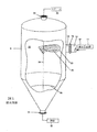
図1は、黒液37の給源11に連結されている従来のフラッシュタンク9の概略図である。黒液37の給源11は母管14、例えば円筒状母管又は混合スプールであり、母管14は、黒液37を受け入れ、黒液37を複数の流れから、フラッシュタンク9に流入する、単一の流れ26に合同させるものであるが、黒液37はパルプを生産するためのクラフト蒸解プロセスにおける加圧されたバッチ式又は連続式の蒸解槽から抽出されることもある。母管14は、黒液37のための、円形断面を有する内部通路(図2参照)を有する。
FIG. 1 is a schematic view of a
黒液37は、母管14からフランジのついた連結部16を通って入口ポート18に流入する。黒液37が従来の出口20を通って入口ポート18を出るとき、黒液37は黒液37の流れ26になる。従来の出口20からフラッシュタンク9の内側側壁面22への遷移は断続的であり、黒液37の流れ26が不均一な態様で従来の出口20を出るときに分断及び乱流が起こる。
The
入口ポート18から、黒液37が従来のフラッシュタンク9の内側側壁面22上にある従来の出口20を通過する。内側側壁面22は一般に円筒状であるか、連続的に湾曲しているか、又は曲線状である表面を有し、それによって内側側壁面は内部チャンバーを規定している。特に入口ポート18の長手軸(図2の40参照)が従来のフラッシュタンク9の中心垂直軸24を横切る半径ラインと同軸であれば、従来の出口20は断面が円形である。入口ポート18が中心垂直軸24に対して実質的に垂直に位置合わせされていなければ、従来の出口20の断面は楕円である。黒液37の流れ26は従来の出口20から流れ、従来の出口20から従来のフラッシュタンク9内の液体の表面28に落下し、それにより従来のフラッシュタンク9における分断及び乱流のさらなる原因となる。
From the
黒液の流れ26が従来のフラッシュタンク9に入るとき、液体の圧力は解放される。母管14における黒液への圧力は実質的に大気圧を超え、例えば5バールゲージ超又は10バールゲージ超である。従来のフラッシュタンク9の内部チャンバー内の圧力は実質的に大気圧であり、例えば0.1〜1.5バールゲージである。黒液37の流れ26が従来のフラッシュタンク9に入るとき、圧力が解放されることによって、黒液37中のスチーム及び他の蒸気が「フラッシュ」されるが、これは液体から蒸気へ相が変化し、黒液の残留液体、例えば凝縮物と分離することを意味する。フラッシュされたスチーム及び他の蒸気30は、従来のフラッシュタンク9の上部部分にある蒸気排出ポート33から排気される。液体を凝縮した黒液32は、従来のフラッシュタンク9の下部部分にある液体排出ポート31から抜き出される。
When the
図2は本開示の例示的なフラッシュタンク10の部分のトップダウンの断面図であり、断面は入口ポート18の高さにおいて取られている。フラッシュタンク10は、入口ポート18において中空の挿入入口チューブ34を付加することにより、図1に示された構成を修正している。挿入入口チューブ34は母管14への入口連結部44を有し、挿入出口36を有する。挿入出口36は狭い隙間61に隣接しているか、又は狭い隙間61により隔てられており、例えば内側側壁面22の領域38から6インチ未満〜1インチ未満(152ミリメートル未満〜25ミリメートル未満)である。
FIG. 2 is a top-down cross-sectional view of a portion of an
領域38は挿入入口チューブの長手軸40に一般に平行である。ある構成において、挿入出口36はフラッシュタンク10の中心垂直軸24を通って延びているライン42にまで延びている。挿入出口36はライン42と位置合わせされることは必要ではないが、本明細書に開示されている例示的な実施形態において、挿入出口36は、ライン42からの距離がフラッシュタンク10の直径の25%未満である。内側側壁面22の領域38の近くに挿入出口36を有することの利点は、挿入出口36からの黒液37の流れが、流れの広範な分断又は乱流なしに、内側側壁面22上に直接的且つスムーズに流れることである。挿入出口36からの黒液37の流れは、内側側壁面22の領域38に実質的に接している。
挿入入口チューブ34の断面積は、チューブの全長(L)に沿って一般に均一である。挿入入口チューブ34の断面の一部は、母管14の入口連結部44からフレアの始点(L1)まで円形である。挿入入口チューブ34の部分(L1)は、長手軸40を有する。挿入入口チューブ34のフレアセクション(L2)(図4の62参照)に沿って、断面は円形から楕円形、競技用トラック、又は他の伸長した形状46に例えば図3に示されるように徐々に変化する。挿入出口36の伸長した形状46の利点は、黒液37が挿入出口36を従来の出口20より速い速度で、及び、従来のフラッシュタンク9よりも内側壁面22にはるかに近接して流出することである。
The cross-sectional area of the
挿入入口チューブ34は、その断面積が挿入入口チューブ34の長さ(L)に沿って実質的に一定であるように設計されている。実質的に一定とは、挿入入口チューブ34の長さ(L)に渡って10%を超えて断面積が変化しないことを意味する。実質的に一定の断面積を維持することは、挿入入口チューブ34を通って流れている黒液37において、分断、例えば乱流及び非層流を最小化することに役立つ。挿入入口チューブ34の長さ(L)に沿って実質的に一定の断面積を維持することは、黒液37が実質的に一定の速度で挿入入口チューブ34を流れることを可能にする。同様に、挿入入口チューブ34の滑らかな内側壁を維持すること、及び挿入入口チューブ34の断面形状を徐々に変化させることにより、黒液37の流れにおける分断が最小化される。さらに、挿入入口チューブ34の初期長さ(L1)の断面積及び直径(D1)を、母管14の断面積及び直径(D1)にマッチングさせることにより、母管14と挿入入口チューブ34との間の遷移部、例えば入口連結部44を通る流れにおける分断が防止される。
The
別の例示的な実施形態において、挿入入口チューブ34の初期長さ(L1)の直径(D1)は、挿入出口36のフレア状セクション(L2)(図4の62参照)の断面積より実質的に大きい断面積を規定する。実質的に大きいとは、断面積が挿入入口チューブ34の長さ(L)に渡って10%を超えて変化することを意味する。
In another exemplary embodiment, the diameter (D 1 ) of the initial length (L 1 ) of the
挿入入口チューブ34は、フラッシュタンク10の従来の入口ポート18に挿入される。入口ポート18の直径(D2)は挿入入口チューブ34の直径(D1)より実質的に大きく、例えば挿入入口チューブ34の直径(D1)の2倍である。挿入入口チューブ34を入口ポート18に取り付けるために、ブラケット及び他の取り付け具が挿入入口チューブ34に固定される。これらの取り付け具は、入口ポート18のフランジの付いた連結部16に連結される円形プレート48を含む。円形プレート48は入口ポート18の末端をシールするものであり、締結具、例えばボルトを受け入れ、円形プレート48をフランジの付いた連結部16に締め付けるための開口52を有する。円形プレート48は、挿入入口チューブ34を受け入れ支持する開口52を有する。開口52は、タンク10の内側側壁面22の領域38に向かう方向に円形プレート48の中心からオフセットしており、挿入入口チューブ34の挿入出口36に隣接している。
The
円形ブレースプレート54は典型的には金属であるが、他の適切な材料でもよく、入口ポート18中にフィットし、入口ポート18の内径(D2)と実質的に同じ直径を有する。円形ブレースプレート54は挿入入口チューブ34のための開口56を有し、例えば溶接されるなどで、挿入入口チューブ34を支持する。円形ブレースプレート54は、挿入入口チューブ34の長手軸40及び入口ポート18に対して一般に垂直である。第1の添え板58、例えば挿入入口チューブ34を支持するのに十分な金属又は他の材料は、三角形のプレートであり、挿入入口チューブ34に対して長手方向の支持を提供し、円形ブレースプレート54から挿入入口チューブ34の長さの一部へ延びている。第1の添え板58は挿入入口チューブ34の外表面に固定、例えば溶接され、挿入入口チューブ34の長手方向の支持を提供する。
The
第2の添え板60は、内側側壁面22の領域38に隣接する挿入入口チューブ34のサイド上、及び挿入入口チューブ34の挿入出口36の近くにある。第2の添え板60は、1インチ(25mm)の高さ及び1インチ(25mm)の幅より小さく(第1の添え板58と比較して)相対的に狭小のリブである。第2の添え板60は、挿入入口チューブ34の補強(stiffening)を提供し、構造的支持を挿入入口チューブ34に提供するために挿入入口チューブ34に固定されている。第2の添え板60はフラッシュタンクの内側壁38、又は入口ポート18に対して着座している。第2の添え板60は、フラッシュタンク10の内側側壁面22に対する挿入出口36の振動を最小化もする。挿入出口36とフラッシュタンク10の内側側壁面22との間の振動を想定して、1インチ(25mm)より小さい狭小の隙間61が、挿入出口36とフラッシュタンク10との間に形成される。狭小の隙間61は第2の添え板60の寸法によって決定される。
The
図3は例示的な挿入入口チューブ34の正面図である。図3の示すように、挿入入口チューブ34のフレア状セクション62は、挿入入口チューブ34の断面部分(L1)における円形の長手軸40からオフセットされている。このオフセット64は、挿入出口36をポジショニングすることに役立ち、その結果、フラッシュタンク10の内側側壁面22及び領域38に近い黒液の流れ(図2における37)をポジショニングすることに役立つ。挿入出口36の形状46は、黒液が挿入出口36からスムーズ且つ直接的に、フラッシュタンク10の内側側壁面22上を流れるように使用される。形状46はフラッシュタンク10の中心垂直軸(図2及び図5における24)に対して平行な方向に伸長されている。形状46は、黒液37がフラッシュタンク10の内部チャンバー(図5参照)に、従来の出口20を通って流れる黒液37よりも高速度で流入することを可能にする。例示的な実施形態において、黒液及び蒸気37は、1秒あたり10フィート(ft/sec)から1秒あたり5000フィートまでの範囲の速度でフラッシュタンク10に流入する。
FIG. 3 is a front view of an exemplary
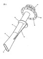
図4は、フラッシュタンク10の入口ポート18に挿入される前の挿入入口チューブ34の例示的な実施形態の斜視図である。挿入入口チューブ34は、前もって製作されたものであり、母管14への入口連結部44のためのフランジ、入口ポート18のフランジ16に取り付けられるための円形プレート48、挿入入口チューブ34へとスライドし、挿入入口チューブ34に対して着座する円形ブレースプレート54、及び挿入入口チューブ34に補強及び長手方向の支持を提供する第1の添え板58及び第2の添え板60を含む。さらに、挿入入口チューブ34は前もって製造されたものであり、フレア状セクション62が競技用トラックの外形を有する形状46を有するように形成されている。挿入出口36の形状46は、挿入入口チューブ34がフラッシュタンク10に挿入される前に、前もって製作されている。
FIG. 4 is a perspective view of an exemplary embodiment of the
別の例示的な実施形態において、フラッシュタンク10は大きな直径の入口ポート18なしで挿入入口チューブ34を直接受け入れるように設計される。挿入入口チューブ34のための適切な支持部材が、挿入入口チューブ34を支持するためにフラッシュタンク10の内側側壁面22の内側及び外側に配置されている。挿入出口36は、挿入入口チューブ34からフラッシュタンク10の内側側壁面22までの黒液の均一な流れを促進するために、例えばフラッシュタンク10に溶接されるなどで、固定されたエッジを有する。
In another exemplary embodiment, the
図5は、フラッシュタンク10の入口ポート18に挿入された後の例示的な挿入入口チューブ34の側面図である。黒液37の流れは母管14に入り、挿入入口チューブ34及びフレア状セクション62をそれぞれ流れる。フレア状領域は、黒液37の流れの圧力、温度及び腐蝕性に耐えるように構成された材料で作製された耐摩耗性チップ72をさらに含む。例示的な実施形態において、耐摩耗性チップ72は全体のフレア状のセクション62を含むことがある。他の例示的な実施形態において、耐摩耗性チップ72は挿入出口36に近接するフレア状領域の一部を含むことがある。さらに他の例示的な実施形態において、耐摩耗性チップ72はフレア状セクション62の全部又は一部を被覆している。挿入出口36は、フラッシュタンク10の中心垂直軸24に実質的に接している。
FIG. 5 is a side view of the exemplary
フラッシュタンク10の中心垂直軸24に対して平行に配向された、競技用トラック、楕円形、又は他の伸長された開口である形状46は、黒液が挿入出口36からフラッシュタンク10の内側側壁面22上へ、スムーズ且つ最小の分断で流れることを補助する。形状46は、黒液37が従来のフラッシュタンクにおける黒液37よりも高速度でフラッシュタンク10に流入することを可能にする。例示的な実施形態において、黒液37は10ft/sec〜5000ft/secの範囲で、かつそれらの間の一つの範囲又は一連の範囲でフラッシュタンクに流入する。黒液37が高速度であり、挿入出口36がフラッシュタンク10の中心垂直軸24と交差する半径ラインに対して垂直に位置していることによって、フラッシュタンク10に流入する黒液が分離流86を形成することが可能になる。この分離流は、フラッシュタンク10における液体の表面28上及び中へと内側側壁面22に沿って接線方向及び下方向に流れる遠心分離流86である。黒液37が内側側壁面22上に流れると、黒液37の流れ26は内側側壁面22に沿って広がり、狭まる。分離流86は、内側側壁表面22に沿って黒液37の鞘(sheaths)又は層(layers)を形成する。分離流86の広がり及び狭まりによって、黒液からのスチーム及び他の蒸気30の放出が促進される。同様に、黒液37の流れにおける乱れ(disturbances)を減少させることによって、黒液37からのスチーム及び他の蒸気30の放出が促進される。
The
本発明は、最も実用的で好ましい実施形態であると現在考えられているものとの関係で説明されたが、本発明は開示された実施形態に限定されるものではなく、種々の修正及び等価な構成が添付の特許請求の範囲内に含まれることを意図していることを理解されたい。
Although the invention has been described in relation to what is presently considered to be the most practical and preferred embodiments, the invention is not limited to the disclosed embodiments, and various modifications and equivalents It is to be understood that such arrangements are intended to be included within the scope of the appended claims.
Claims (15)
フラッシュタンクの側壁によって形成された内部表面を有する内部チャンバー;
前記チャンバーの上部部分に連結されている蒸気排出ポート;
前記チャンバーの下部部分に連結されている液体排出ポート;
挿入出口を有し、前記チャンバーの入口ポートに挿入されたその断面積が挿入入口チューブの長さに沿って実質的に均一である挿入入口チューブを含み、
前記挿入入口チューブは側壁の内側に延びており、前記挿入出口はフラッシュタンクの中心垂直軸に対して実質的に平行に、且つフラッシュタンクの半径ラインに対して実質的に垂直に配向された伸長した断面形状を有し、それによって挿入出口が側壁に実質的に接していることを特徴とするフラッシュタンク。 A flash tank, this flash tank
An internal chamber having an internal surface formed by the sidewalls of the flash tank;
A steam exhaust port connected to the upper portion of the chamber;
A liquid discharge port connected to the lower portion of the chamber;
An insertion inlet tube having an insertion outlet, the cross-sectional area of which is inserted into the inlet port of the chamber being substantially uniform along the length of the insertion inlet tube;
The insertion inlet tube extends inside the side wall, and the insertion outlet is elongated substantially parallel to the central vertical axis of the flash tank and substantially perpendicular to the radial line of the flash tank. A flash tank, characterized in that the insertion outlet is substantially in contact with the side wall.
前記フレア状セクションが、円筒状セクションの長手軸から、挿入出口に近接するフラッシュタンクの側壁の方へ徐々にオフセットされている請求項1に記載のフラッシュタンク。 The insertion inlet tube comprises a cylindrical section having a circular cross section, and a flared section between the circular section and the insertion outlet;
The flash tank of claim 1, wherein the flared section is gradually offset from the longitudinal axis of the cylindrical section toward the side wall of the flash tank proximate to the insertion outlet .
入口ポートに挿入され、入口ポートに固定されるように構成されたその断面積が長さに沿って実質的に均一であるチューブ状セクション、及び
チューブ状セクションの挿入出口を含み、
前記挿入入口チューブアセンブリはチャンバーの入口ポートに挿入されており、
前記挿入入口チューブは側壁の内側に延びており、挿入出口はフラッシュタンクの中心垂直軸に対して実質的に平行に、且つフラッシュタンクの半径ラインに対して実質的に垂直に配向された伸長した断面形状を有し、それによって挿入出口が側壁に実質的に接していることを特徴とする挿入入口チューブアセンブリ。 An insertion inlet tube assembly for a flash tank including a sidewall and an inlet port, the insertion inlet tube assembly comprising:
A tubular section inserted into the inlet port and configured to be secured to the inlet port and having a cross-sectional area that is substantially uniform along the length ; and an insertion outlet of the tubular section;
The insertion inlet tube assembly is inserted into the inlet port of the chamber;
The insertion inlet tube extends inside the sidewall and the insertion outlet extends elongated substantially parallel to the central vertical axis of the flash tank and substantially perpendicular to the radial line of the flash tank. An insertion inlet tube assembly having a cross-sectional shape, whereby the insertion outlet is substantially in contact with the side wall .
前記フレア状セクションが長手軸から、挿入出口に近接するフラッシュタンクの側壁の方へ徐々にオフセットされている請求項5に記載の挿入入口チューブアセンブリ。 The tubular section includes a section having a circular cross section and a longitudinal axis, and a flared section between the circular section and the insertion outlet;
6. The insertion inlet tube assembly of claim 5 , wherein the flared section is gradually offset from the longitudinal axis toward the flash tank sidewall proximate the insertion outlet.
加圧された薬液をフラッシュタンクの挿入入口チューブに供給する工程;
加圧された薬液を挿入入口チューブから挿入出口を通じて側壁の内側表面上にスムーズに流す工程;
加圧された薬液が側壁の内部表面上に流れるとき、加圧された薬液をフラッシュする工程;
フラッシュすることによって形成された蒸気をチャンバーの上部部分を通じて排出する工程;及び
フラッシュすることによって形成された液体をチャンバーの下部部分から排出する工程を含み、
加圧された薬液を挿入入口チューブを通じて流す工程をさらに含み、
前記挿入入口チューブは、加圧された薬液の流路に沿って実質的に均一な断面積を有し、
前記挿入入口チューブがフラッシュタンクの側壁の内側表面を越えて延びており、側壁の内側表面に隣接する挿入出口を含んでいる
ことを特徴とする方法。 A method for flushing pressurized medicinal liquid, the method comprising:
Supplying pressurized chemical solution to the insertion tube of the flash tank;
Smoothly flowing the pressurized drug solution from the insertion inlet tube through the insertion outlet onto the inner surface of the side wall;
Flushing the pressurized chemical when the pressurized chemical flows on the inner surface of the sidewall;
Evacuating vapor formed by flushing through the upper portion of the chamber; and evacuating liquid formed by flushing from the lower portion of the chamber;
Further comprising flowing the pressurized drug solution through the insertion inlet tube,
The insertion inlet tube has a substantially uniform cross-sectional area along the flow path of the pressurized chemical solution;
The method wherein the insertion inlet tube extends beyond the inner surface of the side wall of the flash tank and includes an insertion outlet adjacent to the inner surface of the side wall.
前記挿入入口チューブの初期長さの断面積が、挿入入口チューブのフレア状セクションより実質的に大きい請求項13に記載の方法。 Further comprising flowing the pressurized drug solution through the insertion inlet tube,
14. The method of claim 13 , wherein an initial length cross-sectional area of the insertion inlet tube is substantially larger than a flared section of the insertion inlet tube.
Applications Claiming Priority (4)
| Application Number | Priority Date | Filing Date | Title |
|---|---|---|---|
| US201361827830P | 2013-05-28 | 2013-05-28 | |
| US61/827,830 | 2013-05-28 | ||
| US14/272,941 US9127403B2 (en) | 2013-05-28 | 2014-05-08 | Flash tank with flared inlet insert and method for introducing flow into a flash tank |
| US14/272,941 | 2014-05-08 |
Publications (2)
| Publication Number | Publication Date |
|---|---|
| JP2014231667A JP2014231667A (en) | 2014-12-11 |
| JP6357013B2 true JP6357013B2 (en) | 2018-07-11 |
Family
ID=50841586
Family Applications (1)
| Application Number | Title | Priority Date | Filing Date |
|---|---|---|---|
| JP2014107648A Active JP6357013B2 (en) | 2013-05-28 | 2014-05-26 | Flush tank with flared inlet insert and method for introducing flow into the flash tank |
Country Status (11)
| Country | Link |
|---|---|
| US (2) | US9127403B2 (en) |
| EP (1) | EP2808441B1 (en) |
| JP (1) | JP6357013B2 (en) |
| CN (1) | CN104208889B (en) |
| BR (1) | BR102014012833B1 (en) |
| CA (1) | CA2852258C (en) |
| CL (1) | CL2014001400A1 (en) |
| ES (1) | ES2869946T3 (en) |
| PT (1) | PT2808441T (en) |
| RU (1) | RU2634893C2 (en) |
| ZA (1) | ZA201403534B (en) |
Families Citing this family (8)
| Publication number | Priority date | Publication date | Assignee | Title |
|---|---|---|---|---|
| US9103070B2 (en) * | 2012-02-13 | 2015-08-11 | Andritz Inc. | Flash tank with adjustable inlet |
| US9127403B2 (en) * | 2013-05-28 | 2015-09-08 | Andritz Inc. | Flash tank with flared inlet insert and method for introducing flow into a flash tank |
| DE102015225505A1 (en) * | 2015-12-16 | 2017-06-22 | Rolls-Royce Deutschland Ltd & Co Kg | Wall of a component to be cooled by means of cooling air, in particular a gas turbine combustion chamber wall |
| CN108067009A (en) * | 2018-01-31 | 2018-05-25 | 丹阳同泰化工机械有限公司 | A kind of high efficient gas and liquid separator |
| SE542043C2 (en) * | 2018-05-03 | 2020-02-18 | Valmet Oy | System and method for treatment of a biomass material, a transporting pipe, and a gas separation system |
| EP3623033A1 (en) * | 2018-09-13 | 2020-03-18 | Primetals Technologies Austria GmbH | Device for removing dust from converter gas |
| CN111827998A (en) * | 2019-04-18 | 2020-10-27 | 中国石油天然气集团有限公司 | Real-time sampling device for methane detection in fracturing flow-back fluid |
| WO2021081377A1 (en) * | 2019-10-24 | 2021-04-29 | Johnson Controls Technology Company | Centrifugal flash tank |
Family Cites Families (38)
| Publication number | Priority date | Publication date | Assignee | Title |
|---|---|---|---|---|
| US3081820A (en) | 1958-01-16 | 1963-03-19 | Lummus Co | Pulp preparation |
| FI44746C (en) | 1963-01-11 | 1971-12-10 | Kamyr Ab | Method and device for oxidizing sulphate liquor |
| US3414038A (en) | 1965-06-21 | 1968-12-03 | Kamyr Ab | Heat recovery method and apparatus |
| US4206806A (en) * | 1976-03-15 | 1980-06-10 | Akira Togashi | Heat-conducting oval pipes in heat exchangers |
| US4551198A (en) | 1982-03-30 | 1985-11-05 | Kamyr, Inc. | Method of flashing black liquor |
| CA1209421A (en) | 1982-03-30 | 1986-08-12 | William E. Wiley | Flash tank construction |
| US4501280A (en) | 1983-04-06 | 1985-02-26 | Critikon, Inc. | Automatic identification of cuff size in automated blood pressure monitors |
| JPS60183002U (en) * | 1984-05-17 | 1985-12-04 | 三菱重工業株式会社 | Evaporator |
| US4580324A (en) * | 1984-06-22 | 1986-04-08 | Wynn-Kiki, Inc. | Method for rounding flat-oval tubing |
| US4730669A (en) * | 1986-02-03 | 1988-03-15 | Long Manufacturing Ltd. | Heat exchanger core construction utilizing a diamond-shaped tube-to-header joint configuration |
| US4897157A (en) | 1986-07-08 | 1990-01-30 | Kamyr, Inc. | Make-up liquor and black liquor evaporating processing during pulp production |
| US4981629A (en) * | 1989-07-25 | 1991-01-01 | Cook Jacob J | Method of applying caulking |
| IL91918A0 (en) * | 1989-10-06 | 1990-06-10 | Rosenberg Lior | Fluid drain system for wounds |
| FR2740869B1 (en) * | 1995-11-02 | 1997-12-19 | Valeo Thermique Moteur Sa | HEAT EXCHANGER WITH TUBES OF OVAL OR OBLONG SECTION AND ITS ASSEMBLY METHOD |
| SE511850C2 (en) * | 1997-02-10 | 1999-12-06 | Kvaerner Pulping Tech | Methods and plant for continuous cooking of fiber material |
| US6103058A (en) * | 1997-08-07 | 2000-08-15 | Kvaerner Pulping Ab | Method for the continuous cooking of pulp |
| US6171494B1 (en) | 1997-08-07 | 2001-01-09 | Kvaener Pulping Ab | Hydraulic vessel system having a downwardly feeding separator |
| US6110255A (en) | 1998-04-17 | 2000-08-29 | Barrick Gold Corporation | Nozzle for low pressure flash tanks for ore slurry |
| JP2000176373A (en) * | 1998-12-11 | 2000-06-27 | Saburo Umeda | Tap water pipe with inner surface coated and method |
| JP2000283677A (en) * | 1999-03-30 | 2000-10-13 | Toyo Radiator Co Ltd | Heat exchanger |
| US6346166B1 (en) | 1999-06-14 | 2002-02-12 | Andritz-Ahlstrom Inc. | Flash tank steam economy improvement |
| JP4422305B2 (en) * | 2000-07-27 | 2010-02-24 | 日鉱金属株式会社 | Operation method of copper smelting furnace and blower lance used therefor |
| EP1884296B1 (en) * | 2005-05-27 | 2011-09-21 | Sumitomo Metal Industries, Ltd. | Method of manufacturing ultrathin wall metallic tube by cold working method |
| DE102006003317B4 (en) * | 2006-01-23 | 2008-10-02 | Alstom Technology Ltd. | Tube bundle heat exchanger |
| US20070251256A1 (en) * | 2006-03-20 | 2007-11-01 | Pham Hung M | Flash tank design and control for heat pumps |
| US7549465B2 (en) * | 2006-04-25 | 2009-06-23 | Lennox International Inc. | Heat exchangers based on non-circular tubes with tube-endplate interface for joining tubes of disparate cross-sections |
| US7785514B2 (en) * | 2006-05-18 | 2010-08-31 | Mccarthy Peter T | Snorkels, flexible tubes, mouthpieces and methods |
| US7955421B2 (en) * | 2007-07-17 | 2011-06-07 | Andritz Inc. | Degassing method and apparatus for separating gas from liquids and possibly solids |
| US7493892B1 (en) * | 2007-12-27 | 2009-02-24 | Robert Bosch Gmbh | Self-damping fuel rail |
| AU2008202664A1 (en) * | 2008-06-17 | 2010-01-07 | Rio Tinto Aluminium Limited | Flash tanks |
| FI20090079A (en) | 2009-03-05 | 2010-09-06 | Andritz Inc | Heat recovery from waste cooking liquor at a pulp mill digester |
| US8196909B2 (en) * | 2009-04-30 | 2012-06-12 | Uop Llc | Tubular condensers having tubes with external enhancements |
| US8910702B2 (en) * | 2009-04-30 | 2014-12-16 | Uop Llc | Re-direction of vapor flow across tubular condensers |
| CN201921537U (en) * | 2010-12-20 | 2011-08-10 | 潍坊市元利化工有限公司 | Continuous flash drum |
| DE102011117166A1 (en) * | 2011-10-05 | 2013-04-11 | Sms Meer Gmbh | Plant and method for the continuous molding of longitudinally slit pipes |
| US9103070B2 (en) * | 2012-02-13 | 2015-08-11 | Andritz Inc. | Flash tank with adjustable inlet |
| US8685205B2 (en) * | 2012-07-31 | 2014-04-01 | Andritz Inc. | Flash tank with compact steam discharge assembly |
| US9127403B2 (en) * | 2013-05-28 | 2015-09-08 | Andritz Inc. | Flash tank with flared inlet insert and method for introducing flow into a flash tank |
-
2014
- 2014-05-08 US US14/272,941 patent/US9127403B2/en active Active
- 2014-05-15 ZA ZA2014/03534A patent/ZA201403534B/en unknown
- 2014-05-16 CA CA2852258A patent/CA2852258C/en active Active
- 2014-05-21 RU RU2014120541A patent/RU2634893C2/en active
- 2014-05-23 PT PT141696278T patent/PT2808441T/en unknown
- 2014-05-23 ES ES14169627T patent/ES2869946T3/en active Active
- 2014-05-23 EP EP14169627.8A patent/EP2808441B1/en active Active
- 2014-05-26 JP JP2014107648A patent/JP6357013B2/en active Active
- 2014-05-27 CN CN201410229050.7A patent/CN104208889B/en active Active
- 2014-05-28 BR BR102014012833-6A patent/BR102014012833B1/en active IP Right Grant
- 2014-05-28 CL CL2014001400A patent/CL2014001400A1/en unknown
-
2015
- 2015-07-16 US US14/800,781 patent/US9284684B2/en active Active
Also Published As
| Publication number | Publication date |
|---|---|
| EP2808441A1 (en) | 2014-12-03 |
| RU2014120541A (en) | 2015-11-27 |
| JP2014231667A (en) | 2014-12-11 |
| EP2808441B1 (en) | 2021-04-21 |
| CA2852258C (en) | 2019-12-31 |
| CA2852258A1 (en) | 2014-11-28 |
| US20140352900A1 (en) | 2014-12-04 |
| CN104208889A (en) | 2014-12-17 |
| US9127403B2 (en) | 2015-09-08 |
| US20150315745A1 (en) | 2015-11-05 |
| CN104208889B (en) | 2018-11-16 |
| BR102014012833B1 (en) | 2021-06-22 |
| RU2634893C2 (en) | 2017-11-07 |
| ZA201403534B (en) | 2015-07-29 |
| PT2808441T (en) | 2021-05-21 |
| ES2869946T3 (en) | 2021-10-26 |
| CL2014001400A1 (en) | 2014-12-12 |
| US9284684B2 (en) | 2016-03-15 |
| BR102014012833A2 (en) | 2015-10-13 |
Similar Documents
| Publication | Publication Date | Title |
|---|---|---|
| JP6357013B2 (en) | Flush tank with flared inlet insert and method for introducing flow into the flash tank | |
| JPH11100786A (en) | Removal of floating foreign substance from pulp-feeding system, system and apparatus therefor | |
| UY31102A (en) | TWO CONTAINER REACTOR SYSTEM AND METHOD FOR HYDROLYSIS AND DIGESTION OF WOOD SPLASHES WITH CHEMICAL POTENTIATED WASHING METHOD | |
| FI119553B (en) | Process and apparatus for mass production from sawdust | |
| JP5607751B2 (en) | Method and process for dry discharge in a pressurized pretreatment reactor | |
| US20090020244A1 (en) | Impregnation vessel with convergence side relief and method for heat injection at convergence | |
| CN102844086B (en) | A kind of falling film type stripper decomposed for carbamate | |
| JP6159573B2 (en) | Organic waste treatment equipment | |
| FI78745C (en) | PUMPNING OCH FOERAEDLING AV SAOGSPAON. | |
| US20150176203A1 (en) | Digester apparatus | |
| ZA200805458B (en) | Impregnation vessel with convergence side relief and method for heat injection at convergence | |
| EP3191642B1 (en) | Heating of hydraulic digesters | |
| FI129118B (en) | Method of feeding wood chips to a pre-hydrolysis reactor | |
| US11993895B2 (en) | Method of feeding wood chips to a prehydrolysis reactor | |
| RU2805175C2 (en) | Method for supplying wood chips into preliminary hydrolysis reactor | |
| SE541727C2 (en) | System and method for treating biomass material | |
| JP2006068606A (en) | Treatments equipment of liquid-containing solid | |
| CN202099660U (en) | Bamboo pulp steam heater | |
| US1282635A (en) | Apparatus for the manufacture of cellulose. | |
| US20080271860A1 (en) | Method and apparatus to distribute the inflow of liquors in batch digester | |
| AU2011232752A1 (en) | Impregnation Vessel with Single Convergence with Side Relief at Vessel Bottom Prior to Discharge |
Legal Events
| Date | Code | Title | Description |
|---|---|---|---|
| A621 | Written request for application examination |
Free format text: JAPANESE INTERMEDIATE CODE: A621 Effective date: 20170214 |
|
| A977 | Report on retrieval |
Free format text: JAPANESE INTERMEDIATE CODE: A971007 Effective date: 20171215 |
|
| A131 | Notification of reasons for refusal |
Free format text: JAPANESE INTERMEDIATE CODE: A131 Effective date: 20180105 |
|
| RD02 | Notification of acceptance of power of attorney |
Free format text: JAPANESE INTERMEDIATE CODE: A7422 Effective date: 20180119 |
|
| RD04 | Notification of resignation of power of attorney |
Free format text: JAPANESE INTERMEDIATE CODE: A7424 Effective date: 20180131 |
|
| A521 | Request for written amendment filed |
Free format text: JAPANESE INTERMEDIATE CODE: A523 Effective date: 20180322 |
|
| TRDD | Decision of grant or rejection written | ||
| A01 | Written decision to grant a patent or to grant a registration (utility model) |
Free format text: JAPANESE INTERMEDIATE CODE: A01 Effective date: 20180522 |
|
| A61 | First payment of annual fees (during grant procedure) |
Free format text: JAPANESE INTERMEDIATE CODE: A61 Effective date: 20180615 |
|
| R150 | Certificate of patent or registration of utility model |
Ref document number: 6357013 Country of ref document: JP Free format text: JAPANESE INTERMEDIATE CODE: R150 |
|
| R250 | Receipt of annual fees |
Free format text: JAPANESE INTERMEDIATE CODE: R250 |
|
| R250 | Receipt of annual fees |
Free format text: JAPANESE INTERMEDIATE CODE: R250 |
|
| R250 | Receipt of annual fees |
Free format text: JAPANESE INTERMEDIATE CODE: R250 |