JP6356871B2 - Network system - Google Patents
Network system Download PDFInfo
- Publication number
- JP6356871B2 JP6356871B2 JP2017103072A JP2017103072A JP6356871B2 JP 6356871 B2 JP6356871 B2 JP 6356871B2 JP 2017103072 A JP2017103072 A JP 2017103072A JP 2017103072 A JP2017103072 A JP 2017103072A JP 6356871 B2 JP6356871 B2 JP 6356871B2
- Authority
- JP
- Japan
- Prior art keywords
- communication
- control
- information
- analysis
- mode
- Prior art date
- Legal status (The legal status is an assumption and is not a legal conclusion. Google has not performed a legal analysis and makes no representation as to the accuracy of the status listed.)
- Active
Links
Images


Classifications
-
- H—ELECTRICITY
- H04—ELECTRIC COMMUNICATION TECHNIQUE
- H04L—TRANSMISSION OF DIGITAL INFORMATION, e.g. TELEGRAPHIC COMMUNICATION
- H04L63/00—Network architectures or network communication protocols for network security
- H04L63/14—Network architectures or network communication protocols for network security for detecting or protecting against malicious traffic
- H04L63/1408—Network architectures or network communication protocols for network security for detecting or protecting against malicious traffic by monitoring network traffic
- H04L63/1425—Traffic logging, e.g. anomaly detection
-
- H—ELECTRICITY
- H04—ELECTRIC COMMUNICATION TECHNIQUE
- H04L—TRANSMISSION OF DIGITAL INFORMATION, e.g. TELEGRAPHIC COMMUNICATION
- H04L12/00—Data switching networks
- H04L12/66—Arrangements for connecting between networks having differing types of switching systems, e.g. gateways
-
- H—ELECTRICITY
- H04—ELECTRIC COMMUNICATION TECHNIQUE
- H04L—TRANSMISSION OF DIGITAL INFORMATION, e.g. TELEGRAPHIC COMMUNICATION
- H04L63/00—Network architectures or network communication protocols for network security
- H04L63/02—Network architectures or network communication protocols for network security for separating internal from external traffic, e.g. firewalls
- H04L63/0209—Architectural arrangements, e.g. perimeter networks or demilitarized zones
-
- H—ELECTRICITY
- H04—ELECTRIC COMMUNICATION TECHNIQUE
- H04L—TRANSMISSION OF DIGITAL INFORMATION, e.g. TELEGRAPHIC COMMUNICATION
- H04L63/00—Network architectures or network communication protocols for network security
- H04L63/02—Network architectures or network communication protocols for network security for separating internal from external traffic, e.g. firewalls
- H04L63/029—Firewall traversal, e.g. tunnelling or, creating pinholes
-
- H—ELECTRICITY
- H04—ELECTRIC COMMUNICATION TECHNIQUE
- H04L—TRANSMISSION OF DIGITAL INFORMATION, e.g. TELEGRAPHIC COMMUNICATION
- H04L63/00—Network architectures or network communication protocols for network security
- H04L63/14—Network architectures or network communication protocols for network security for detecting or protecting against malicious traffic
- H04L63/1408—Network architectures or network communication protocols for network security for detecting or protecting against malicious traffic by monitoring network traffic
- H04L63/1416—Event detection, e.g. attack signature detection
-
- H—ELECTRICITY
- H04—ELECTRIC COMMUNICATION TECHNIQUE
- H04L—TRANSMISSION OF DIGITAL INFORMATION, e.g. TELEGRAPHIC COMMUNICATION
- H04L63/00—Network architectures or network communication protocols for network security
- H04L63/14—Network architectures or network communication protocols for network security for detecting or protecting against malicious traffic
- H04L63/1441—Countermeasures against malicious traffic
-
- H—ELECTRICITY
- H04—ELECTRIC COMMUNICATION TECHNIQUE
- H04L—TRANSMISSION OF DIGITAL INFORMATION, e.g. TELEGRAPHIC COMMUNICATION
- H04L45/00—Routing or path finding of packets in data switching networks
- H04L45/64—Routing or path finding of packets in data switching networks using an overlay routing layer
-
- H—ELECTRICITY
- H04—ELECTRIC COMMUNICATION TECHNIQUE
- H04L—TRANSMISSION OF DIGITAL INFORMATION, e.g. TELEGRAPHIC COMMUNICATION
- H04L67/00—Network arrangements or protocols for supporting network services or applications
- H04L67/01—Protocols
- H04L67/10—Protocols in which an application is distributed across nodes in the network
Description
本発明は、ネットワークシステム、制御装置、通信装置、通信制御方法および通信制御プログラムに関する。 The present invention relates to a network system, a control device, a communication device, a communication control method, and a communication control program.
近年、ネットワークを介した攻撃の手法が高度化し、従来の事前防御によるセキュリティ対策では対処が困難になってきている。高性能・高機能のセキュリティ機器によりこれらの攻撃手法に対処しようとしているが、機器の費用や運用・管理の手間を考慮すると一般のユーザ宅や中小企業への導入が難しい。このため、安価な機器の導入で高度なセキュリティ対策を実現することが望ましいが、そのような機器では性能・機能が限られている。 In recent years, attack techniques via networks have become more sophisticated, and it has become difficult to cope with conventional security measures based on prior defense. We are trying to cope with these attack methods with high-performance and high-function security devices, but it is difficult to introduce them into general user homes and small and medium-sized enterprises, considering the cost of the devices and the effort of operation and management. For this reason, it is desirable to implement advanced security measures by introducing inexpensive devices, but such devices have limited performance and functions.
例えば、ホームNW(Network)や中小の企業NW等のユーザNWには、最小限の機能を備える安価な機器のみを導入し、この機器とユーザNWの外部にある機能とが連携することで高度なセキュリティ対策を実現すること、つまりユーザNWのセキュリティのアウトソースが期待される。 For example, a user NW such as a home NW (Network) or a small and medium-sized company NW introduces only an inexpensive device having a minimum function, and this device and a function outside the user NW cooperate with each other. Realization of various security measures, that is, outsourcing of the security of the user NW is expected.
例えば、セキュリティ対策として、ユーザNWと外部NWとの間の通信トラフィック(通信パケット、通信フローも含む)全てをインターネット上のデータセンタなどに配置される外部機能を経由またはミラーリングさせることで、外部機能でユーザNWの通信トラフィックをもれなく監視する技術が考えられる。また、例えば、ユーザNWのトラフィックをサンプリングしてデータセンタなどに配置されている外部機能へ送信して異常検知する技術がある。 For example, as a security measure, all communication traffic (including communication packets and communication flows) between a user NW and an external NW is routed or mirrored via an external function arranged in a data center on the Internet. Therefore, a technique for monitoring all the communication traffic of the user NW can be considered. In addition, for example, there is a technique for detecting anomalies by sampling the traffic of the user NW and transmitting it to an external function arranged in a data center or the like.
また、例えば、ユーザNWの外部でユーザNWから流れてくる通信トラフィックをIDS(Intrusion Detection System)にかけて宛先のアプリケーションサーバ(APサーバ)への不正通信であるか否かを判定して管理者へ通知する技術がある(例えば、特許文献1参照)。具体的には、特定のAPサーバへの不正アクセスが疑われる通信を、当該APサーバを担当するISP(Internet Services Provider)内のIDSを備えるパケット転送装置へ割り振り、そこで悪性と判定された場合は管理者へ通知する。これにより、転送装置は任意のAPサーバへの通信ではなく特定のサーバへの通信に特化してIDS処理を実現できるため、処理負荷が低減される。 Further, for example, communication traffic flowing from the user NW outside the user NW is subjected to IDS (Intrusion Detection System) to determine whether the communication is unauthorized communication to the destination application server (AP server) and notified to the administrator. There is a technique (see, for example, Patent Document 1). Specifically, when communication that is suspected of unauthorized access to a specific AP server is allocated to a packet transfer apparatus having an IDS in an ISP (Internet Services Provider) that is in charge of the AP server, Notify the administrator. As a result, the transfer apparatus can realize the IDS processing specialized for communication to a specific server, not communication to an arbitrary AP server, and thus the processing load is reduced.
しかしながら、上記の従来技術では、ユーザ回線の帯域を圧迫することなく、また、精度を低下させることなく、悪性通信を検知して、ユーザ通信を適切に保護することができないという課題があった。つまり、上記の通信トラフィック全てを監視する技術は、帯域が圧迫されるという問題があった。また、上記の全ての通信トラフィックを対象とせず、単純にサンプリングして異常検知するする技術では、精度が低下するという問題があった。 However, the above-described prior art has a problem that it is not possible to detect malignant communication and appropriately protect user communication without squeezing the bandwidth of the user line and without reducing accuracy. That is, the technology for monitoring all the communication traffic has a problem that the bandwidth is compressed. Further, the technique of simply sampling and detecting an abnormality without targeting all the above-described communication traffic has a problem that accuracy is lowered.
また、特定のAPサーバへの不正アクセスが疑われる通信トラフィックを、当該サーバが属するサービスプロバイダ(ISP、MSSP(Managed Security Service Provider)等)のIDSに転送して悪性を判定する技術では、保護の対象がAPサーバのため、ユーザネットワークの通信が保護できないという問題点があった。 In addition, a technology for judging malignancy by transferring communication traffic suspected of unauthorized access to a specific AP server to the IDS of the service provider (ISP, MSSP (Managed Security Service Provider), etc.) to which the server belongs, Since the target is an AP server, there is a problem that communication of the user network cannot be protected.
上述した課題を解決し、目的を達成するために、本発明のネットワークシステムは、通信装置と、ネットワークを介して前記通信装置と通信する制御装置とを備えたネットワークシステムであって、前記通信装置は、該通信装置を経由する通信を制御する通信制御部と、前記通信に関する情報のうち、一部の情報を部分情報として構成して前記制御装置に送信する収集部と、を備え、前記制御装置は、前記通信装置から受信した部分情報を用いて分析して前記通信に異常があるか否かを判断する分析部と、前記分析部によって前記通信に異常があると判断された場合には、前記通信が前記通信装置から前記制御装置へ送信されるよう、前記通信制御部に対して通信経路を制御する制御判断部と、通信経路の制御により送信されてきた通信が悪性の通信であるか否かを判定する解析部と、を備えたことを特徴とし、前記制御判断部は、さらに、前記解析部によって前記通信が悪性の通信であると判定された場合には、前記通信制御部に対して該悪性の通信を制限するよう制御し、前記制御装置は、前記部分情報を基にして生成される特徴空間を示す情報であって、前記分析部が行う分析に適用されるモデル情報を記憶する記憶部をさらに備え、前記分析部は、さらに、複数の通信装置の各々を経由する通信に対応するモデル情報を共有して構成される共有モデル情報を前記記憶部に記憶させ、前記共有モデル情報を用いて、前記通信に異常があるか否かを判断することを特徴とする。 In order to solve the above-described problems and achieve the object, a network system of the present invention is a network system including a communication device and a control device that communicates with the communication device via a network. Includes a communication control unit that controls communication via the communication device, and a collection unit that configures a part of the information related to the communication as partial information and transmits the partial information to the control device. An apparatus that analyzes using the partial information received from the communication device to determine whether or not the communication is abnormal; and when the analysis unit determines that the communication is abnormal The control judgment unit for controlling the communication path to the communication control unit and the communication transmitted by the control of the communication path are bad so that the communication is transmitted from the communication device to the control device. An analysis unit that determines whether or not the communication is, and the control determination unit further, when the analysis unit determines that the communication is a malignant communication, The communication control unit is controlled to limit the malignant communication, and the control device is information indicating a feature space generated based on the partial information, and is applied to the analysis performed by the analysis unit A storage unit that stores model information to be stored, and the analysis unit further includes shared model information configured to share model information corresponding to communication via each of the plurality of communication devices in the storage unit. Storing, and using the shared model information, it is determined whether or not there is an abnormality in the communication.
本発明によれば、ユーザネットワークの回線の帯域の圧迫や異常・悪性通信の検知に関する精度の低下を抑えて、悪性通信を検知して、ユーザネットワークの通信を適切に保護することができるという効果を奏する。 Advantageous Effects of Invention According to the present invention, it is possible to detect the malignant communication and appropriately protect the communication of the user network by suppressing the decrease in the accuracy related to the compression of the bandwidth of the user network and the detection of the abnormality / malignant communication. Play.
以下に、本願に係るネットワークシステム、制御装置、通信装置、通信制御方法および通信制御プログラムの実施の形態を図面に基づいて詳細に説明する。なお、この実施の形態により本願に係るネットワークシステム、制御装置、通信装置、通信制御方法および通信制御プログラムが限定されるものではない。 Hereinafter, embodiments of a network system, a control device, a communication device, a communication control method, and a communication control program according to the present application will be described in detail with reference to the drawings. Note that the network system, the control device, the communication device, the communication control method, and the communication control program according to the present application are not limited by this embodiment.
[第一の実施の形態]
以下の実施の形態では、第一の実施の形態に係るネットワークシステムの構成、通信装置の構成、制御装置の構成、ネットワークシステムの全体の処理の流れ、通信装置および制御装置それぞれの処理の流れを順に説明し、最後に第一の実施の形態による効果を説明する。
[First embodiment]
In the following embodiment, the configuration of the network system, the configuration of the communication device, the configuration of the control device, the overall processing flow of the network system, the processing flow of each of the communication device and the control device according to the first embodiment These will be described in order, and finally the effects of the first embodiment will be described.
[ネットワークシステムの構成]
図1は、第一の実施の形態に係るネットワークシステムの構成を示す図である。図1に示すネットワークシステム100では、ユーザNW30内に設置された通信装置10と、ユーザNW30の外に設置された制御装置20とを有する。通信装置10と制御装置20とは、外部NW60を介して接続される。
[Network system configuration]
FIG. 1 is a diagram showing a configuration of a network system according to the first embodiment. The
図1に示すように、通信装置10の配置場所は、ユーザNW30側である。例えば、通信装置10は、ユーザNW30側のインターネット通信するための外縁ルータに組込まれてもよいし、外縁ルータとユーザNW30内におけるPCなどの端末40との間に置かれてもよい。後者の場合は、インライン型(トランスペアレント型)の接続となる。つまり、通信装置10を経由する通信、またはその一部が処理の対象となる。また、通信装置10は、収集装置11と通信制御装置12とから構成される。
As illustrated in FIG. 1, the
収集装置11は、ユーザNW30を流れて通信装置10を経由する通信トラフィックの一部を収集して、通信トラフィックの部分情報として制御装置20の収集管理装置21に送信する。なお、収集装置11は、収集した通信トラフィックの一部をそのまま収集管理装置21に送信してもよいし、収集した通信トラフィックの一部のさらにその一部のみを部分情報として送信してもよいし、もしくは、集約または統計化した情報を通信トラフィックの部分情報として外部に送信してもよい。
The
通信制御装置12は、制御装置20から受けた制御命令にしたがって通信トラフィックを制御する。なお、後に詳述するが、通信トラフィックの制御処理として、通信モードの変更に伴う通信モード制御とセキュリティ制御(パケットフィルタリングなど)とがある。
The
制御装置20の配置場所は、ユーザNW30の外部であって、制御NW70側である。例えば、制御装置20は、通信キャリアNWやISPのNW、インターネット上のデータセンタに設置される。また、制御装置20は、収集管理装置21、分析装置22、制御判断装置23、解析装置24、および、通信制御装置25の5つの装置で構成される。なお、制御装置20を一つの装置とし、収集管理装置21、分析装置22、制御判断装置23、解析装置24、および、通信制御装置25それぞれの機能を一台で有してもよい。
The location of the
収集管理装置21は、収集装置11から送信される部分情報を収集し、分析装置22へ送信する。
The
分析装置22は、収集管理装置21から受信した部分情報に対して、例えば、機械学習の異常検知などによる分析を行い、その分析結果を制御判断装置23に出力する。また分析結果を機械学習のモデル情報として記憶して以降の分析に適用する。入力として受け付けた部分情報を用いて構成される特徴ベクトルとモデル情報(たとえば、特徴ベクトル群で構成される、特徴ベクトル群を集約して構成される、特徴ベクトル空間または特徴空間など)を用いて分析し、この特徴ベクトルが異常であるか否かを分析結果として出力する。さらに、機械学習することで、この特徴ベクトルをモデル情報に反映することで更新させて以降の分析の精度を向上させる。
The
制御判断装置23は、分析装置22から受けた分析結果を基に通信モードを決定し、各通信制御装置12、25へ通信モードに従った通信モード制御を行うよう命令する。また、制御判断装置23は、解析装置24から受けた解析結果を基に通信モードやセキュリティ制御の内容を決定し、各通信制御装置12、25へこれらの決定に従った通信制御を行うよう命令する。
The
解析装置24は、受信する通信トラフィックに対して深い解析を行い、マルウェア等に感染した悪性通信であるか否かを判定して判定結果を制御判断装置23に出力する。例えば、解析装置24は、悪性である「黒」、悪性ではない「白」、白黒判定できない「灰」のいずれであるかを判定する。なお、「灰」については、多段階であってもよく、例えばより黒に近い5から白に近い1までの5段階レベルで、判定しても良い。判定結果には、判定対象の通信のプロトコル番号、宛先や送信元アドレス・ポート番号等が含まれており、この情報を用いて各通信制御装置12、25へセキュリティ制御が行われる。
The
通信制御装置25は、制御判断装置23から受けた制御命令にしたがって通信トラフィックを制御する。なお、通信トラフィックの制御処理として、通信モードの変更に伴う通信モード制御とセキュリティ制御とがある。
The
ユーザNW30内には、PCなどの通信機器である端末40とインターネットと通信するためのルータ80(または終端装置)とがある。通信装置10は、端末40とルータ80の間に接続され、端末40がインターネット通信する通信トラフィックはすべて通信装置10を介してルータ経由で外部NW60と送受信されるものとする。
Within the
ここで、各装置について具体例を挙げて説明すると、例えば、収集装置11は、sFlowエージェント、収集管理装置21は、sFlowコレクタ、各通信制御装置12、25は、OpenFlow(例えば、「https://www.opennetworking.org/」参照)対応スイッチ、およびGREやL2TPなどのトンネリング機能を基に構成される。
Here, each device will be described with a specific example. For example, the
また、例えば、分析装置22は、異常検知処理として、オンライン機械学習並列分散処理フレームワークJubatus(例えば、NTT技術ジャーナル 2012.10、pp.30-35、「http://www.ntt.co.jp/journal/1210/files/jn201210030.pdf」参照)の異常検知を行うことができる装置である。また、例えば、解析装置24は、Deep Packet Inspectionを行えるレイヤ2からレイヤ7のアプリケーション通信までを識別して深く解析し、悪性通信の振る舞いを検出、遮断できる装置である。
In addition, for example, the
また、解析装置24は、悪性通信(黒)であると判定した場合は、該当するメッセージログを出力する。また、解析装置24は、怪しい通信(灰)であると判定した場合は、該当するメッセージログを出力し、さらに怪しさにレベルがある場合には、そのレベルを示す情報もあわせて出力する。また、解析装置24は、悪性通信でない(白)と判定した場合は、該当するメッセージログを出力する、またはメッセージログを出力しないことで、悪性通信でないことを外部の制御判断装置23や利用者へ通知する。
If the
制御判断装置23は、分析装置22や解析装置24の結果を基に命令内容を判断してOpenFlowコントローラを介して、OpenFlow対応スイッチ(例えば、Open vSwitch(http://openvswitch.org/))へ命令してもよく、通信制御装置12、25の間のトンネリングの構築と削除は別途命令することとしてもよい。
The
また、OpenFlowコントローラを各通信制御装置12、25に組み込み、制御判断装置23が、各OpenFlowコントローラに対して制御命令を送信し、命令を受信したOpenFlowコントローラが対象のOpenFlow対応スイッチに対してフローエントリの書き込みなどの制御を行うこととしてもよい。
Also, the OpenFlow controller is incorporated in each of the
[通信装置の構成]
次に、図2を用いて、図1に示した通信装置10の構成を説明する。図2は、第一の実施の形態に係る通信装置の構成を示すブロック図である。図2に示すように、この通信装置10は、収集装置11と通信制御装置12とで構成される。
[Configuration of communication device]
Next, the configuration of the
収集装置11は、通信に関する情報のうち、一部の情報を部分情報として構成して制御装置20に送信する。または、ユーザネットワーク内の収集可能な全通信を収集して、その一部を部分情報として構成することとしてもよい。ここで、ユーザネットワーク内の通信とは、通信装置10を経由する通信であって、たとえばユーザネットワーク内に閉じた通信やユーザネットワークとインターネットなどの外部のネットワークの間の通信を示す。収集装置11は、抽出部11aと記憶部11bとを有する。
The
記憶部11bは、部分情報を収集するための規定が定義された収集ルールを記憶する。例えば、記憶部11bは、収集ルールとして、抽出部11aが通信トラフィックを抽出するための条件を規定した抽出ルールや、抽出した部分情報を収集管理装置21へ送信するための条件が規定された送信ルールを記憶する。
The storage unit 11b stores a collection rule in which a rule for collecting partial information is defined. For example, the storage unit 11b transmits, as a collection rule, an extraction rule that defines a condition for the
抽出部11aは、記憶部11bに記憶された収集ルールに基づいて、通信トラフィックを抽出し、必要に応じて一時的に記憶部11bに記憶させる。また、抽出部11aは、抽出ルールの要件を満たす部分情報を抽出し、送信ルールの要件を満たす契機で収集管理装置21へ送信する。例えば、抽出部11aは、所定数のパケットを取得するごとに、収集ルールの要件を満たす部分情報を収集管理装置21へ送信する。
The
通信制御装置12は、記憶部12aとトンネル部12bと通信制御部12cとを有する。記憶部12aは、通信モード制御やセキュリティ制御に必要な制御ルールを記憶する。
The
ここで、抽出部11aの収集ルールについて説明する。収集装置11の記憶部11bに記憶される収集ルールは、異常検知などを行う分析装置22への入力となる特徴ベクトルを構成する各要素の情報(例えば、通信方向ごとの時刻情報、通信セッションの持続時間、ユーザまたはユーザNW30を識別する識別情報、送信元IPアドレス、宛先IPアドレス、送信元ポート番号、宛先ポート番号、アプリケーション識別情報、データサイズ、名前解決のためのDNSクエリ及びレスポンスの内容情報やこの問合せの時間間隔、回数や解決された名前のTTL(Time To Live)など)と、これらの情報をサンプリングやサンプリングに類する形式で集約する、または統計化する計算方法、さらに部分情報を収集管理装置21へ送信させる契機(収集する時間間隔を契機、所定パケット数収集を契機とするなど)を示す情報から構成される。例えば、契機を示す情報として、所定の時間間隔を契機としてもよいし、所定パケット数を収集したことを契機としてもよい。
Here, the collection rule of the
また、通信トラフィックの収集として、例えば、SNMPやsFlow、Netflow、IPFIXで取得できるデータ、及び、そのサンプリング方法が一例として挙げられる。または、OpenFlowで扱える統計情報を取得する仕組みを利用してもよい。この場合には、OpenFlow対応スイッチで収集される統計情報をOpenFlowの仕様に従ってOpenFlowコントローラに送信されることになる。例えば、制御判断装置23にOpenFlowコントローラが組込まれている場合は、統計情報を収集した制御判断装置23は収集管理装置21へ転送し、また各通信制御装置(通信制御装置12と通信制御装置25)にOpenFlowコントローラが組込まれている場合は通信制御装置12上で収集した統計情報を収集管理装置21へ転送する(収集装置11を経由してもよい)。また、通信に利用されているレイヤ7のアプリケーションを識別できる手段が組込まれている場合は、この識別情報を部分情報に含めてもよい。
Further, as an example of the collection of communication traffic, data that can be acquired by SNMP, sFlow, Netflow, IPFIX, and the sampling method thereof can be cited as an example. Alternatively, a mechanism for acquiring statistical information that can be handled by OpenFlow may be used. In this case, statistical information collected by the OpenFlow compatible switch is transmitted to the OpenFlow controller according to the OpenFlow specification. For example, when the OpenFlow controller is incorporated in the
その他にも任意の情報を任意の形式で集約する構成を組込んでもよい。フレームまたはパケットをキャプチャして分解することで必要な要素情報を抽出できる。また、収集ルールに該当する要件を満たす所定の通信トラフィックをそのまま送信させてもよいし、この通信トラフィックの一部を送信させてもよい。この場合は、後述する収集管理装置21側で部分情報を生成するか、または、受信した情報から機械学習などに適用する特徴ベクトルを生成する。例えば、sFlowの技術を適用した場合は、サンプリングベースの技術であり、エージェント(収集装置11に相当)ではなくコレクタ(収集管理装置21に相当)にて特徴ベクトルを生成する。
In addition, a configuration for collecting arbitrary information in an arbitrary format may be incorporated. Necessary element information can be extracted by capturing and disassembling a frame or packet. Further, predetermined communication traffic that satisfies the requirements corresponding to the collection rule may be transmitted as it is, or a part of the communication traffic may be transmitted. In this case, partial information is generated on the
トンネル部12bは、対向の制御装置20の通信制御装置25との間でトンネルを構築する。トンネル部12bは、通信モードがミラーリングモードまたはインラインモードのときに、解析装置24へ通信トラフィックを流すために対向の通信制御装置25の通信制御部25cとの間でトンネルを構築する。通信制御部12cは、通信装置10を経由する通信を制御する。具体的には、通信制御部12cは、通信モードに基づく通信モード制御と、パケットフィルタリングなどのセキュリティ制御を行う。
The
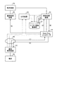
[制御装置の構成]
次に、図3を用いて、図1に示した制御装置20の構成を説明する。図3は、第一の実施の形態に係る制御装置の構成を示すブロック図である。図3に示すように、この制御装置20は、収集管理装置21と分析装置22と制御判断装置23と解析装置24と通信制御装置25とで構成される。
[Configuration of control device]
Next, the configuration of the
制御装置20は、通信装置10を流れる通信トラフィックを観測し、異常な通信(悪性、または悪性と断定できないが正常な通信の振る舞いとは異なる通信)と判定した場合や悪性通信と判定した場合に通信モードを変更することで通信モード制御を、悪性であり通信遮断が必要であると判定した場合はセキュリティ制御を、通信装置10の通信制御装置12および/または制御装置20の通信制御装置25に対して命令する。
When the
収集管理装置21は、収集部21aおよび抽出制御部21bを有する。収集部21aは、通信装置10から部分情報を収集して分析装置22へ送信する。抽出制御部21bは、収集装置11に対して予め収集ルールを送信する。
The
分析装置22は、収集管理装置21を介して通信装置10から受信した部分情報を分析し、分析した分析結果を用いて、ユーザネットワーク内の通信に異常があるか否かを判断する。また、分析装置22は、分析/学習部22aおよび記憶部22bを有する。なお、記憶部22bは、通信の異常を判断する判断基準となるルールを記憶する。
The
分析/学習部22aは、収集管理装置21から受け取った部分情報を異常検知などの機械学習により分析し、その結果を制御判断装置23へ通知する。また、分析/学習部22aは、機械学習の学習結果をモデル情報として更新し、更新したモデル情報を記憶部22bに格納する。
The analysis /
分析/学習部22aは、分析および学習の方法として、例えば密度ベースの外れ値検出法であるLOF(Local Outlier Factor)等を利用してもよい。ここで、分析および機械学習について詳細に説明する。まず、特徴ベクトル化について、特徴ベクトルを構成する要素をあらかじめ定義し、分析装置22に登録しておく。
The analysis /
通信パケットである場合、例えば、送信元/宛先IPアドレスやMACアドレス、プロトコル番号(TCP/UDP等を示す番号)、ポート番号、データ部の認証情報(有りの場合は1、無しの場合は0とする等)、データサイズ、通信に利用されているアプリケーションを識別する識別情報など通信パケットから取得できるあらゆる情報のうち、分析・学習に必要な要素を予め定義しておき、パケットの入力を受付けた場合には、このパケットを分解して定義した必要な要素(IPv4アドレスを例えば8ビットごとの要素とする複数要素で構成してもよい)を抽出し、この要素で構成される特徴ベクトル(要素がn個であればn次元の数値ベクトルとなる)を作成する。 In the case of a communication packet, for example, source / destination IP address or MAC address, protocol number (a number indicating TCP / UDP or the like), port number, and data portion authentication information (1 if present, 0 if not present) Etc.) Among the information that can be acquired from the communication packet, such as data size, identification information that identifies the application used for communication, etc., the elements necessary for analysis and learning are defined in advance, and the packet input is accepted. If necessary, a necessary element (which may be composed of a plurality of elements having an IPv4 address as an element of every 8 bits, for example) extracted by decomposing this packet is extracted, and a feature vector ( If there are n elements, it is an n-dimensional numerical vector).
これは、収集装置11の収集ルールに基づいて抽出部11aで行ってもよく、とにかく特徴ベクトル化に必要な情報を部分情報として収集装置11から収集管理装置21へ送信し、収集管理装置21がこの部分情報から特徴ベクトルを生成することとしてもよい。
This may be performed by the
異常判定(分析)について、分析装置22の記憶部22bが記憶するこれまでの学習結果であるモデル情報(例えば、特徴ベクトル群であって、所定の学習または分類アルゴリズムで分類されている1以上の集合となる)に対して、特徴ベクトル化された入力情報を入力として与えた場合、空間の距離や密度に基づいて異常(またはアノマリ、通常モデルからの逸脱度合いで示されるもの)か非異常かを判定することができる。
For abnormality determination (analysis), model information (for example, a feature vector group, which is stored in the storage unit 22b of the
学習について、特徴ベクトルを所定の記憶部22bに記憶するとともに、記憶された特徴ベクトル群を、所定の学習アルゴリズムに基づいて分類する。異常検知の学習アルゴリズムとして、例えばLOFが適用可能である。ここで学習とは、記憶部22bに特徴ベクトル情報を記憶して、記憶部22bに記憶されている特徴ベクトル情報群から集合の特徴情報(分類であれば集合を分類するために線引きする境界線など)を導出する。この特徴情報を用いることで分析が可能となる。学習により、より多様で多数の特徴ベクトルがモデル情報に反映されることで、モデル情報を用いた分析の精度を高くすることができる。 For learning, feature vectors are stored in a predetermined storage unit 22b, and the stored feature vector group is classified based on a predetermined learning algorithm. As an abnormality detection learning algorithm, for example, LOF can be applied. Here, learning means that feature vector information is stored in the storage unit 22b, and set feature information from the feature vector information group stored in the storage unit 22b (a boundary line that is drawn to classify the set if classification is used) Etc.). Analysis can be performed by using this feature information. By learning, a greater variety of feature vectors are reflected in the model information, so that the accuracy of analysis using the model information can be increased.
制御判断装置23は、判断部23a、制御命令部23bおよび記憶部23cを有する。記憶部23cは、各通信制御装置12、25の状態情報等を記憶する。記憶部23cは、状態情報として、例えば、どのユーザまたはユーザNW30のどの通信トラフィックをどの通信モードで経路制御しているか、また通信モードの遷移の履歴、どのようなセキュリティ制御を実施しているかをユーザまたはユーザNW30ごとに対応付けて記憶する。
The
判断部23aは、分析装置22によって分析された分析結果を用いて、通信モードを判断する。具体的には、判断部23aは、分析装置22から分析結果を受け取ると、分析結果を基に判断して通信制御装置12の通信モードを決定する。
The
制御命令部23bは、分析装置22によって通信に異常があると判断された場合には、該異常と判断された通信に関する情報(分析結果として異常と判定された特徴ベクトルに該当・対応する通信)が通信制御装置12から解析装置24へ転送される(経由する、またはミラーリングされる)ようにユーザNW30内の通信制御装置12に対して通信経路を制御する。また、制御命令部23bは、解析装置24によってユーザNW30内の通信が悪性の通信であると判定された場合には、該悪性の通信を制限するように制御する。
When it is determined by the
例えば、制御命令部23bは、判断部23aが決定した通信モードが現在の通信モードと異なる場合は、各通信制御装置12、25に決定した通信モードに従うよう通信モード制御命令を送信する。また、制御命令部23bは、解析装置24から解析結果を受け取り、セキュリティ制御が必要であると判断した場合には、通信制御装置12(および/または25)にセキュリティ制御命令を送信する。
For example, when the communication mode determined by the
ここで、通信制御装置12、25の記憶部12a、25bに記憶される制御ルールについて説明する。制御ルールは、通信モードに基づく経路制御とセキュリティ制御のためのルールである。図4に示すように、通信モードには、通常モードとミラーリングモードとインラインモードとが規定されており、分析装置22の分析結果を考慮した制御判断装置23の判断結果に応じて、各通信制御装置12、25が各モードに遷移することとなる。
Here, the control rule memorize | stored in the memory |
通信モードが通常モードの場合は、内部NW(ユーザNW30)と通信する通信インターフェース及び外部NW60と通信する通信インターフェースを備える通信装置10の通信制御装置12に対してブリッジ/スイッチ、ルーティング処理により受信した通信トラフィックを宛先へそのまま転送されるように制御する経路制御ルールが設定される。
When the communication mode is the normal mode, the
また、ミラーリングモードおよびインラインモードの場合には、通信制御装置12と対向の通信制御装置25との間でトンネルを構築する。このトンネルは静的に構築されているものでもよく、当該通信モードに切り替わる契機で未構築であれば動的にトンネルが構築されるものでもよい。この場合、通常モードに切り戻す契機で動的に構築済みトンネルを削除することとすればよい。
In the case of the mirroring mode and the inline mode, a tunnel is established between the
ミラーリングモードの場合には、通信装置10の通信制御装置12に対して、内部NWと通信する通信インターフェースや外部NW60と通信する通信インターフェースから受信した通信トラフィックを宛先へそのまま転送するとともに、受信した通信トラフィックをトンネル対向側に向けてミラーリングしてトンネル経由で転送するように制御する経路制御ルールが設定される。一方、制御装置20の通信制御装置25に対して、トンネル対向側からトンネル経由で受信した通信トラフィックを解析装置24へ転送するように制御する経路制御ルールが設定される。
In the mirroring mode, the communication traffic received from the communication interface that communicates with the internal NW or the communication interface that communicates with the
インラインモードの場合には、通信装置10の通信制御装置12に対して、内部NWと通信する通信インターフェースから受信した通信トラフィックをトンネル対向側に向けてトンネル経由で転送するように、外部NW60と通信する通信インターフェースから受信した通信トラフィックをトンネル対向側に向けてトンネル経由で転送するように、トンネル対向側からトンネル経由で受信した通信トラフィックを元の宛先に対して転送するように制御する経路制御ルールが設定される。さらに、通信装置10の通信制御装置12は、制御装置20の通信制御装置25からトンネル経由で受信した通信トラフィックを当該通信トラフィックの宛先へ転送するように制御する経路制御ルールが設定される。
In the case of the inline mode, the
一方、制御装置20の通信制御装置25に対して、トンネル対向側からトンネル経由で受信した通信トラフィックを解析装置24へ転送するように、解析装置24から受信した通信トラフィックをトンネル対向側にトンネル経由で転送するように制御する経路制御ルールが設定される。
On the other hand, the communication traffic received from the
セキュリティ制御は、悪性通信や所定の条件を満たす、あやしい通信(白黒灰の判定において灰に相当)と判定された通信を遮断する。所定の条件を満たすあやしい通信の遮断は、安全サイドに倒して念のための遮断であり、遮断の後で正常通信であると判定された場合は、その時点でこの遮断を解除する制御命令を送信することとなる。制御判断装置23が遮断すべきと判断した通信を遮断するよう通信制御装置12および/または25へ命令する。例えば、レイヤ3のIPアドレスやIPアドレスレンジのレベル、レイヤ4のTCP/UDPやポート番号のレベル、アプリケーションレイヤでの遮断の制御が可能な場合は、通信トラフィックから遮断するべき特定のアプリケーションを識別して該当するアプリケーションを識別可能な情報を用いて当該アプリケーション通信を遮断する。URLフィルタを適用できる場合は、遮断するべき特定のURLやFQDNをフィルタに設定するよう制御してもよい。メールフィルタを適用できる場合は、遮断するべき特定のメールアドレスやドメインをフィルタに設定するよう制御してもよい。遮断等のセキュリティ制御の設定に必要な情報は、解析装置24が出力する解析結果に含まれていて、制御判断装置23は受け取った解析結果を用いて通信制御装置に命令して制御する。
The security control blocks malicious communication or communication determined to be suspicious communication that satisfies a predetermined condition (corresponding to ash in the determination of black and white ash). Blocking a suspicious communication that satisfies a predetermined condition is a safety block by defeating the safety side. If it is determined that the communication is normal after the blocking, a control command for canceling the blocking is issued at that time. Will be sent. The
解析装置24は、制御判断装置23の判断部23aによって通信に異常があると判断された場合には、ミラーリングモードで機能している場合はこれに基づく経路制御によって転送されてくる通信を受信し、この通信に対して解析を行い、ユーザNW30内の通信が悪性の通信であるか否かを判定する。
If the
解析装置24は、詳細解析部24aを有する。詳細解析部24aは、通信トラフィックの内容を深く解析して、通信が、白(正常通信)、黒(悪性通信)、灰(白黒断定できない通信)のいずれであるかを判定し、判定対象の通信を示す送信元・宛先のIPアドレスやポート番号、アプリケーション識別情報などのうち少なくとも1以上からなる組とともに判定結果として制御判断装置23へ送信する。
The
通信制御装置25は、トンネル部25aと記憶部25bと通信制御部25cとを有する。トンネル部25aは、対向の通信装置10の通信制御装置12との間でトンネルを構築する。例えば、トンネル部25aは、ミラーリングモードとインラインモードのときに、解析装置24へ通信トラフィックを流すために対向の通信制御装置12の通信制御部12cとの間でトンネルを構築する。
The
記憶部25bは、通信モード制御やセキュリティ制御に必要な制御ルールを記憶する。通信制御部25cは、通信モードに基づく通信モード制御を行う。また、通信制御部25cは、セキュリティ制御を行う。
The
ここで、図5を用いて、第一の実施の形態に係るネットワークシステム100による通信制御処理の一連の流れを説明する。図5は、第一の実施の形態に係るネットワークシステムによる通信制御処理の一連の流れを説明する図である。
Here, a series of communication control processing by the
図5に示すように、収集装置11は、ユーザNW30を流れて通信制御装置12を経由する通信トラフィックまたはその一部を収集する(図5の(1)参照)。そして、収集装置11は、通信トラフィックの部分情報として制御装置20の収集管理装置21に送信する(図5の(2)参照)。
As illustrated in FIG. 5, the
続いて、収集管理装置21は、収集装置11から送信される部分情報を収集し、分析装置22へ送信する(図5の(3)参照)。そして、分析装置22は、収集管理装置21から受信した部分情報に対して、例えば、機械学習の異常検知などによる分析を行い、その結果を制御判断装置23に出力する(図5の(4)参照)。
Subsequently, the
その後、制御判断装置23は、分析装置22から受けた分析結果を基に通信モードを決定し、各通信制御装置12、25へ通信モードに従った通信モード制御を行うよう命令する(図5の(5)参照)。また、解析装置24は、受信する通信トラフィックに対して深い解析を行い、マルウェア等に感染した悪性通信であるか否かを判定して判定結果を制御判断装置23に出力する(図5の(6)参照)。
Thereafter, the
そして、制御判断装置23は、解析装置24から受けた解析結果を基に通信モードやセキュリティ制御の内容を決定し、各通信制御装置12、25へこれらの決定に従った通信制御を行うよう命令する(図5の(7)参照)。例えば、通信モードが通常モードの場合には、通信制御装置12は、端末40とインターネット上のサイト50との間の通信をそのまま宛先へ転送する(図5の矢印A参照)。また、例えば、通信モードがミラーリングモードの場合には、通信制御装置12は、通信をそのまま宛先(インターネット上のサイト50または端末40)へ転送するとともに、この両方向の通信をミラーリングして制御装置20の通信制御装置25を介して解析装置24へも転送する(図5の矢印B参照)。また、例えば、通信モードがインラインモードの場合には、通信制御装置12は、端末40とインターネット上のサイト50との通信を、通信制御装置12、通信制御装置25および解析装置24を経由させてユーザNW30側の外縁ルータを経て宛先へ転送する。より具体的には、端末40からインターネット上のサイト50宛の通信であれば、端末40から通信制御装置12、通信制御装置25を経て解析装置24を経由して、そこから折り返して通信制御装置25、通信制御装置12を経てインターネット上のサイト50宛に送信される。インターネット上のサイト50から端末40宛の通信であれば、この逆向きの順序の通信となる(図5の矢印C参照)。
The
[ネットワークシステムの処理の一例]
次に、図6を用いて、第一の実施の形態に係るネットワークシステム100における通信制御処理の流れについて説明する。図6は、第一の実施の形態に係るネットワークシステムにおける通信制御処理の流れを示すシーケンス図である。
[Example of network system processing]
Next, the flow of communication control processing in the
図6に示すように、収集装置11は、ユーザNW30を流れて通信制御装置12を経由する通信トラフィックまたはその一部を収集し、通信トラフィックの部分情報として制御装置20の収集管理装置21に送信する(ステップS101)。続いて、収集管理装置21は、収集装置11から送信される部分情報を収集し、分析装置22へ送信する(ステップS102)。
As illustrated in FIG. 6, the
そして、分析装置22は、収集管理装置21から受信した部分情報に対して、例えば、機械学習の異常検知などによる分析を行う(ステップS103)。そして、分析装置22は、分析結果を制御判断装置23に出力する(ステップS104)。
Then, the
その後、制御判断装置23は、分析装置22から受けた分析結果を基に制御内容として通信モードを判断し(ステップS105)、各通信制御装置12、25へ通信モードに従った通信モード制御を行うよう命令して(ステップS106)、各通信制御装置12、25に制御内容を通知する(ステップS107)。そして、各通信制御装置12、25は、通知された通信モード制御を設定する(ステップS108、S109)。
Thereafter, the
ここで、通信制御装置12は、通信モードがミラーリングモードまたはインラインモードの場合には、解析装置24へ通信トラフィックを送信する(ステップS110)。そして、解析装置24は、受信する通信トラフィックに対して深い解析を行い(ステップS111)、マルウェア等に感染した悪性通信であるか否かを判定して解析結果を制御判断装置23に出力する(ステップS112)。
Here, when the communication mode is the mirroring mode or the inline mode, the
そして、制御判断装置23は、解析装置24から受けた解析結果を基に通信モードやセキュリティ制御の内容を判断し(ステップS113)、各通信制御装置12、25へ判断結果に応じた通信制御を行うよう命令して(ステップS114)、通信モードやセキュリティ制御の内容を各通信制御装置12、25に通知する(ステップS115)。そして、各通信制御装置12、25は、通知された通信モードやセキュリティ制御を設定する(ステップS116、S117)。
Then, the
このように、ユーザNW30の外部に配置される制御装置20は、ユーザNW30を流れる通信トラフィックの一部または統計化された情報である部分情報を効率よく収集し、収集した通信トラフィックの部分情報に対して分析を行う。そして、分析により異常な通信の振る舞いであると判定した場合は、監視すべきユーザNW30の通信トラフィックが制御装置20に流れるように通信モードを変更させる。
As described above, the
また、通信モード変更によって、ミラーリングモードやインラインモードで通信の経路制御をすることで部分情報ではない通信トラフィックそのもの(ペイロードも対象としてもよい)を観測することでより深い解析にかける。解析によりマルウェアなどに感染したことを示す悪性通信と判定した場合は、この通信トラフィックを一時的または恒久的に遮断するよう制御する。悪性ではなく、正常な振る舞いの通信であると判断した場合は通信モードを例えば通常モードへ変更する。 Further, by changing the communication mode, the communication path is controlled in the mirroring mode or the inline mode, and the communication traffic itself (which may be the payload) that is not partial information is observed for deeper analysis. If the analysis determines that the communication is malicious communication indicating that it has been infected with malware or the like, the communication traffic is controlled to be temporarily or permanently blocked. If it is determined that the communication is not malignant but has a normal behavior, the communication mode is changed to, for example, the normal mode.
普段はユーザNW30の通信トラフィックのうちの部分情報を観測することで、ユーザNW30の通信性能への影響を低減する。そして、この観測で異常検知の判定を行う。これを所定の契機で継続する。異常であると判断した場合は、該当通信トラフィックを深く解析し、さらに悪性通信であると判定した場合には、当該通信トラフィックに対してセキュリティ制御を実施する。 Usually, the influence on the communication performance of the user NW30 is reduced by observing partial information in the communication traffic of the user NW30. Then, the abnormality detection is determined by this observation. This is continued at a predetermined opportunity. When it is determined that the communication traffic is abnormal, the communication traffic is analyzed deeply, and when it is determined that the communication is malicious communication, security control is performed on the communication traffic.
[収集装置の処理の一例]
次に、図7を用いて、収集装置11における収集処理の流れについて説明する。図7は、第一の実施の形態に係る収集装置における収集処理の流れを示すフローチャートである。
[Example of collection device processing]
Next, the flow of collection processing in the
図7に示すように、収集装置11は、通信トラフィックを観測し(ステップS201)、通信トラフィックが抽出ルールに該当するかを判定する(ステップS202)。この結果、抽出ルールに該当する場合には(ステップS202肯定)、通信に関する情報を抽出し、または、統計化する(ステップS203)。
As illustrated in FIG. 7, the
そして、収集装置11は、通信に関する情報を抽出し、または、統計化した際に、送信ルールに該当するか否かを判定する(ステップS204)。例えば、収集装置11は、送信ルールに規定される所定の時間間隔が経過したか、もしくは、送信ルールに規定される所定パケット数を収集したかを判定する。
And the
この結果、収集装置11は、送信ルールに該当する場合には(ステップS204肯定)、部分情報を収集管理装置21へ送信する(ステップS205)。また、抽出ルールに該当しない場合(ステップS202否定)、または、送信ルールに該当しない場合には(ステップS204否定)、ステップS201の処理に戻って処理を繰り返す。
As a result, when the transmission device corresponds to the transmission rule (Yes at Step S204), the
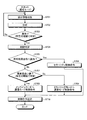
[制御装置の処理の一例]
次に、図8、9、10を用いて、制御装置20における通信制御処理の流れについて説明する。図8は、第一の実施の形態に係る制御装置の通常モードにおける通信制御処理の流れを示すフローチャートである。図9は、第一の実施の形態に係る制御装置のミラーリングモードにおける通信制御処理の流れを示すフローチャートである。図10は、第一の実施の形態に係る制御装置のインラインモードにおける通信制御処理の流れを示すフローチャートである。
[Example of control device processing]
Next, the flow of communication control processing in the
まず、図8を用いて、通常モードにおける通信制御処理について説明する。図8に示すように、まず、制御装置20の収集管理装置21が、収集装置11から送信される部分情報を収集する(ステップS301)。そして、分析装置22は、収集管理装置21から受信した部分情報に対して、例えば、機械学習の異常検知などによる分析を行う(ステップS302)。
First, the communication control process in the normal mode will be described with reference to FIG. As shown in FIG. 8, first, the
そして、分析装置22は、分析した分析結果を用いて、ユーザNW30内の通信に異常があるか否かを判断する(ステップS303)。この結果、分析装置22は、通信に異常がないと判定した場合には(ステップS303否定)、ステップS301の処理に戻る。また、制御判断装置23は、通信に異常があると判定された場合には(ステップS303肯定)、分析装置22から受けた分析結果を基に制御内容として通信モードを判定する(ステップS304)。
Then, the
ここで、制御判断装置23は、通信の異常の度合いが所定の閾値より高いか否かを判定する(ステップS305)。この結果、制御判断装置23は、通信の異常の度合いが所定の閾値より高い場合には(ステップS305肯定)、インラインモードへ遷移する通信モード制御を行うよう各通信制御装置12、25に命令する(ステップS306)。また、制御判断装置23は、通信の異常の度合いが所定の閾値以下である場合には(ステップS305否定)、ミラーリングモードへ遷移する通信モード制御を行うよう各通信制御装置12、25に命令する(ステップS307)。そして、各通信制御装置12、25は、命令された通信モード制御を設定する(ステップS308)。なお、通信モードが通常モードと、ミラーリングモードまたはインラインモードの2つのみで実施される場合は、ステップS305は省略されて、ステップS306またはステップS307のいずれかが択一的に選択されることとなる。
Here, the
次に、図9を用いて、ミラーリングモードにおける通信制御処理について説明する。図9に示すように、解析装置24は、ミラーリングモードにおいて、通信制御装置12から受信する通信トラフィックに対して深い解析を行い(ステップS401)、通信が悪性である「黒」、悪性ではない「白」、白黒判定できない「灰」のいずれであるかを判定する(ステップS402)。
Next, communication control processing in the mirroring mode will be described with reference to FIG. As shown in FIG. 9, in the mirroring mode, the
この結果、解析装置24が「黒」と判定した場合には、制御判断装置23は、パケットフィルタリングなどのセキュリティ制御を行うことを各通信制御装置12、25に命令し(ステップS403)、ステップS407に移行する。
As a result, when the
また、解析装置24が「白」と判定した場合には、制御判断装置23は、通常モードへ遷移する通信モード制御を行うよう各通信制御装置12、25に命令し(ステップS404)、ステップS407に移行する。
If the
また、解析装置24が「灰」と判定した場合には、制御判断装置23は、通信が要注意であるか、すなわち、「灰」という判定結果が所定のレベル以上であるか否かを判定する(ステップS405)。例えば、より黒に近い5から白に近い1までの5段階レベルである場合には、「3」以上であるか否かを判定する。
When the
この結果、制御判断装置23は、所定のレベル以上である場合には(ステップS405肯定)、インラインモードへ遷移する通信モード制御を行うよう各通信制御装置12、25に命令し(ステップS406)、ステップS407に移行する。また、所定のレベル以上でない場合には(ステップS405否定)、ステップS401の処理に戻って、上記の処理を繰り返す。そして、ステップS407において、通信制御装置25は、命令された通信モードやセキュリティ制御を設定して、処理を終了する。なお、通信モードが通常モードとミラーリングモードの2つのみで実施される場合、ステップS405、ステップS406は省略され、ステップ402で灰判定となった場合はステップS401の処理に戻ってもよい。また、あらかじめ設定しておくことで、より安全性を高めるために灰判定を黒判定と同じ扱いとしてもよく、または過剰な通信遮断による弊害を避けるため、灰判定を白判定と同じ扱いとしてもよい。
As a result, if the
次に、図10を用いて、インラインモードにおける通信制御処理について説明する。図10に示すように、解析装置24は、インラインモードにおいて、通信制御装置12から受信する通信トラフィックに対して深い解析を行い(ステップS501)、通信が悪性である「黒」、悪性ではない「白」、白黒判定できない「灰」のいずれであるかを判定する(ステップS502)。
Next, communication control processing in the inline mode will be described with reference to FIG. As shown in FIG. 10, in the inline mode, the
この結果、解析装置24が「黒」と判定した場合には、制御判断装置23は、パケットフィルタリングなどのセキュリティ制御を行うことを各通信制御装置12、25に命令し(ステップS503)、ステップS507に移行する。
As a result, when the
また、解析装置24が「灰」と判定した場合には、制御判断装置23は、通信が要注意であるか、すなわち、「灰」という判定結果が所定のレベル以上であるか否かを判定する(ステップS504)。例えば、より黒に近い5から白に近い1までの5段階レベルである場合には、「3」以上であるか否かを判定する。
When the
この結果、制御判断装置23は、所定のレベル以上でない場合には(ステップS504否定)、ミラーリングモードへ遷移する通信モード制御を行うよう各通信制御装置12、25に命令し(ステップS505)、ステップS507に移行する。また、所定のレベル以上である場合には(ステップS504肯定)、ステップS501の処理に戻って、上記の処理を繰り返す。
As a result, if the level is not equal to or higher than the predetermined level (No at Step S504), the
また、解析装置24が「白」と判定した場合には、制御判断装置23は、通常モードへ遷移する通信モード制御を行うよう各通信制御装置12、25に命令し(ステップS506)、ステップS507に移行する。そして、ステップS507において、通信制御装置25は、命令された通信モードやセキュリティ制御を設定して、処理を終了する。なお、通信モードが通常モードとインラインモードの2つのみで実施される場合、ステップS504、ステップS505は省略され、ステップ502で灰判定となった場合はステップS501の処理に戻ってもよい。また、あらかじめ設定しておくことで、より安全性を高めるために灰判定を黒判定と同じ扱いとしてもよく、または過剰な通信遮断による弊害を避けるため、灰判定を白判定と同じ扱いとしてもよい。
If the
[第一の実施の形態の効果]
このように、第一の実施の形態に係るネットワークシステム100は、通信装置10は、該通信装置10を経由する通信に関する情報のうち、一部の情報または統計化された情報を部分情報として制御装置20に送信する。そして、制御装置20は、通信装置10から受信した部分情報を分析し、分析された分析結果を用いて、ユーザNW30内の通信に異常があるか否かを判断する。そして、制御装置20は、ユーザNW30内の通信に異常があると判断された場合には、通信モードを変更することで経路制御を行い、ユーザNW30を流れる通信を用いて解析を行い、ユーザNW30内の通信が悪性の通信であるか否かを判定する。制御装置20は、ユーザNW30内の通信に異常があると判断された場合には、該異常と判断された通信に関する情報(例えば、異常と判定された特徴を持つ通信トラフィック)が通信装置10から解析装置24へ転送されるようにユーザNW30内の通信装置10を制御する。そして、解析装置24によってユーザNW30内の通信が悪性の通信であると判定された場合には、該悪性の通信を制限するように制御する。
[Effect of the first embodiment]
As described above, in the
これにより、第一の実施の形態に係るネットワークシステム100は、ユーザNW30から外部NW60であるインターネットなどへアクセスするための通信回線の帯域の圧迫や異常・悪性通信の検知に関する精度の低下を抑えて、悪性通信を検知して、ユーザ通信を適切に保護することが可能である。つまり、通常時は、通信装置10で収集した部分情報を制御装置20が分析を行って異常を検知する処理を行い、異常を検知した場合にはユーザNW30の通信に関する情報を解析装置24へ転送させ、転送された全データに対してIDSやIPS(Intrusion Prevention System)等で深い解析を行うことにより悪性通信を判定して悪性通信を対処する。これにより、ユーザNW回線の帯域の圧迫や異常・悪性通信の検知に関する精度の低下を抑えて、悪性通信を判定し、悪性通信を対処することが可能となる。
As a result, the
[第二の実施の形態]
上記の第一の実施の形態では、部分情報を異常検知などの機械学習により分析し、さらに機械学習の結果をモデル情報として更新する場合を説明したが、解析装置24の解析結果を分析装置22のモデル情報に反映または付加することで、モデル情報を更新してもよい。
[Second Embodiment]
In the first embodiment described above, the case where partial information is analyzed by machine learning such as abnormality detection and the result of machine learning is updated as model information has been described. However, the analysis result of the
例えば、分析装置22における異常検知の学習結果であるモデル情報では、モデル情報を構成する特徴ベクトル群の密度や距離などに基づいて所定の閾値により、異常となる空間領域であるか否か判定される。ここで異常とは、通常とは異なるものであって、この時点では必ずしも悪性通信であると断定できるものではない。
For example, in the model information that is the learning result of the abnormality detection in the
そこで、第二の実施の形態では、解析装置24で得られた判定結果であるラベル(白/黒/灰)と、この判定結果に該当する通信トラフィックから構成される特徴ベクトルとを組として、モデル情報にマッピング(写像)させる場合を例にして説明する。なお、第一の実施の形態と同様の処理については説明を省略する。
Therefore, in the second embodiment, a label (white / black / gray) that is a determination result obtained by the
図11は、第二の実施の形態に係るネットワークシステムによる通信制御処理の一連の流れを説明する図である。図11に示すように、第二の実施の形態に係る制御装置20において、分析装置22は、機械学習の異常検知などによる分析を行うと、その結果を制御判断装置23に出力するとともに(図11の(4)参照)、分析結果を機械学習のモデル情報として記憶する。
FIG. 11 is a diagram for explaining a series of communication control processing by the network system according to the second embodiment. As shown in FIG. 11, in the
そして、制御判断装置23は、解析装置24から受けた解析結果を基に通信モードやセキュリティ制御の内容を決定し、各通信制御装置12、25へこれらの決定に従った通信制御を行うよう命令した後(図11の(7)参照)、解析装置24から受け取った解析結果を分析装置22に送信する。そして、分析装置22は、解析装置23から受けた解析結果を分析装置22のモデル情報の空間上にマッピングする(図11の(8)参照)。
The
ここで、解析結果をモデル情報の空間上にマッピングする処理について、図12の例を用いて説明する。図12は、特徴ベクトル空間へのマッピングの概念図である。図12に示すように、特徴ベクトル空間においては、通常モードにおける分析装置22による異常検知の特徴ベクトルと、解析装置24の判定結果に対応する特徴ベクトルとが存在する。
Here, the process of mapping the analysis result on the model information space will be described with reference to the example of FIG. FIG. 12 is a conceptual diagram of mapping to the feature vector space. As shown in FIG. 12, in the feature vector space, there are a feature vector of abnormality detection by the
この解析装置24の判定結果に対応する特徴ベクトルには、解析装置24の判定結果を示すラベルが付されている。そして、解析装置24の判定結果に対応する特徴ベクトルを含む所定の領域に該当する特徴ベクトルは、ラベルに基づく判定基準による制御が行われる。例えば、「異常」と判定された空間領域に「黒」と判定された結果がラベルとしてマッピングされている場合には、異常ではなく悪性通信と判定する。なお、黒、白、灰の全てのラベルを付する場合に限定されるものではなく、黒および/または白と判定されたもののみをラベル付することとしてもよい。
A label indicating the determination result of the
また、例えば、ラベル付された特徴ベクトルと所定の距離や密度を満たす特徴ベクトルに対しては、ラベルに基づいた判定をしてもよい。また、例えば、判断基準を示す制御ルールをあらかじめ決めておき、これに従って制御内容を決定することとしてもよい。 Further, for example, for a feature vector that satisfies a predetermined distance and density from a labeled feature vector, determination based on the label may be performed. Further, for example, a control rule indicating a determination criterion may be determined in advance, and the control content may be determined according to the control rule.
ここで判断基準の一例について図13を用いて説明する。図13は、異常判定処理に用いられる判定基準の一例を示す図である。図13に例示するように、解析装置24の解析結果である「マッピング情報」と、分析装置22の分析結果である「モデル情報」との組み合わせごとに、通信モードが規定されている。
Here, an example of the determination criterion will be described with reference to FIG. FIG. 13 is a diagram illustrating an example of a determination criterion used in the abnormality determination process. As illustrated in FIG. 13, a communication mode is defined for each combination of “mapping information” that is an analysis result of the
例えば、モデル情報が「異常と判定された空間領域」であり、この領域の中に「白判定」を示すマッピング情報が該当している場合には、この領域に該当する通信(特徴ベクトル)を分析により検知した時、「通常モード」による通信モード制御が行われる。つまり、異常と判定された空間領域ではあるが、悪性通信ではない「白」と判定されたラベルであるため、通常モードのままとしている。なお、図13において、括弧に「(またはミラーリングモード)」と記載されており、括弧内の通信モードが決定されてもよく、通常モードとするかミラーリングモードとするかはユーザや管理者に予め選択させておけばよい。 For example, if the model information is a “space area determined to be abnormal” and the mapping information indicating “white determination” corresponds to this area, the communication (feature vector) corresponding to this area is displayed. When detected by analysis, the communication mode control by the “normal mode” is performed. In other words, although it is a spatial region determined to be abnormal, the label is determined to be “white” which is not malignant communication, and thus the normal mode is maintained. In FIG. 13, “(or mirroring mode)” is described in parentheses, and the communication mode in parentheses may be determined. Whether the normal mode or the mirroring mode is set is determined in advance by the user or the administrator. Just let me choose.
また、例えば、モデル情報が「異常と判定されない空間領域」であり、この領域の中に「黒判定」を示すマッピング情報が該当している場合には、この領域に該当する通信(特徴ベクトル)を分析により検知した時、「セキュリティ制御」が行われる。つまり、異常と判定されない空間領域であっても、悪性通信ではある「黒」と判定されたラベルであるため、セキュリティ制御に遷移する。 Further, for example, when the model information is “a space area that is not determined to be abnormal”, and mapping information indicating “black determination” corresponds to this area, communication (feature vector) corresponding to this area When security is detected by analysis, "security control" is performed. That is, even in a spatial region that is not determined to be abnormal, since it is a label that has been determined to be “black” for malicious communication, the process proceeds to security control.
第一の実施の形態では、通常モードからセキュリティ制御へ遷移することはなかったが、第二の実施の形態では、上記したようにラベルを適用することで、異常の内容を反映することが可能となるため、例えば、悪性通信(黒)であるから異常であるなどと判断できるため、通常モードからセキュリティ制御へ遷移させることができる。 In the first embodiment, there is no transition from the normal mode to the security control, but in the second embodiment, the contents of the abnormality can be reflected by applying the label as described above. Therefore, for example, since it is a malignant communication (black), it can be determined that the communication is abnormal. Therefore, the normal mode can be shifted to the security control.
なお、異常検知だけではなく、例えばクラスタリングの機械学習にも適用することができる。セキュリティ判定結果を機械学習によって分類された各クラスタにマッピングさせることで、各クラスタにラベル付けをすることができる。ここで、クラスタリングとは、機械学習において、特徴量の関連性・類似性が高いものをグルーピングすることであり、分類対象の集合を、内的結合と外的分離が達成されるような部分集合に分割する。 Note that the present invention can be applied not only to abnormality detection but also to clustering machine learning, for example. By mapping the security judgment result to each cluster classified by machine learning, each cluster can be labeled. Here, clustering is the grouping of features with high relevance / similarity in machine learning, and the set of classification targets is a subset that achieves internal coupling and external separation. Divide into
このマッピング処理に使用するラベルと特徴ベクトルの組は、解析装置24に別途収集装置11と同等の装置を組込む、または解析装置24の手前(解析装置24と通信制御装置25の間など)にインライン接続の形態で収集装置11を置く、もしくは解析装置24に流れてくる通信トラフィックに対してミラーリング接続の形態で収集装置11を置くことで、解析装置24に流れてくる通信トラフィックに関する情報を収集する。
A set of labels and feature vectors used for this mapping process is separately incorporated in the
そして、収集装置11相当の装置が部分情報を抽出して特徴ベクトルを構成し、さらに、解析装置24のセキュリティ判定結果であるラベル相当の情報を特徴ベクトルに対応付けて、分析装置22のモデル情報にマッピングさせる。この対応付けした特徴ベクトルとラベル情報は、制御判断装置23を介して分析装置22の記憶部22bに記憶してもよい。また制御判断装置23の記憶部23cに記憶してもよく、この場合は分析装置22から出力される分析結果と組み合せてセキュリティ制御判断に適用してもよい。
Then, a device corresponding to the
つまり、分析結果である特徴ベクトルの空間領域に対して意味づけ(ラベルづけ)を行うことによって、異常検知/分析結果を基に通信モードの変更を省略してセキュリティ制御を行うことができる。または、異常検知/分析結果を基に通常モードからミラーリングモード、インラインモードへ遷移するところを、ミラーリングモードを省略して通常モードからインラインモードへ遷移させる判断をとってもよい。 That is, by giving meaning (labeling) to the spatial region of the feature vector that is the analysis result, security control can be performed without changing the communication mode based on the abnormality detection / analysis result. Alternatively, based on the abnormality detection / analysis result, the transition from the normal mode to the mirroring mode or the inline mode may be determined by omitting the mirroring mode and shifting from the normal mode to the inline mode.
次に、図14を用いて、第二の実施の形態にかかるネットワークシステム100における通信制御処理の流れについて説明する。図14は、第二の実施の形態に係るネットワークシステムにおける通信制御処理の流れを示すシーケンス図である。なお、図14におけるステップS601〜S617の処理は、図6で説明した第一の実施の形態に係るネットワークシステム100における通信制御処理のステップS101〜S117と同様であるため、説明を省略する。
Next, the flow of communication control processing in the
各通信制御装置12、25は、通知された通信モードやセキュリティ制御を設定した後(ステップS616、S617)、制御判断装置23は、解析装置24から受け取った解析結果を分析装置22に送信する(ステップS618)。そして、分析装置22は、解析装置24から受けた解析結果を分析装置22のモデル情報の空間上にマッピングする(ステップS619)。
After the
次に、図15を用いて、制御装置20における通信制御処理の流れについて説明する。図15は、第二の実施の形態に係る制御装置の通常モードにおける通信制御処理の流れを示すフローチャートである。
Next, the flow of communication control processing in the
図15に示すように、制御判断装置23は、分析装置22から受けた分析結果を基に制御内容として通信モードを判定する際に(ステップS704)、解析結果照合に該当するか否かを判定する(ステップS705)。ここで、例えば、上記の分析結果である特徴ベクトルによる空間領域(クラスタリングされた空間領域または異常/通常を分ける空間領域)にラベル付された特徴ベクトルが該当する場合は、この空間領域全体またはこの空間領域内であってラベル付された特徴ベクトルから所定の距離・範囲内の空間領域を、そのラベルで代表される空間領域とみなす。この空間領域に該当するか否か、さらに該当するラベルは何なのかを分析装置22が判定する。この結果、解析結果照合に該当する場合には(ステップS705肯定)、パケットフィルタリングなどのセキュリティ制御を行うことを各通信制御装置12、25に命令する(ステップS706)。
As shown in FIG. 15, when determining the communication mode as the control content based on the analysis result received from the analysis device 22 (step S <b> 704), the
つまり、上述したように、解析装置24の解析結果(判定結果)に対応する特徴ベクトルには、さらに、解析装置24の判定結果を示すラベルが付されている。このため、解析装置24の判定結果に対応する特徴ベクトルを含む所定の領域に該当する部分情報の特徴ベクトルは、ラベルに基づく判定基準による制御が行われる。例えば、「異常」と判定された空間領域に「黒」と判定された結果がラベルとしてマッピングされている場合には、異常ではなく悪性通信と判定し、パケットフィルタリングなどのセキュリティ制御を行う。
That is, as described above, the feature vector corresponding to the analysis result (determination result) of the
このように、第二の実施の形態に係るネットワークシステムでは、解析装置24の解析結果と該当する特徴ベクトルを分析装置22のモデル情報に反映し、モデル情報を更新することで、機械学習の結果であるモデル情報に意味づけをして、制御判断の材料にすることが可能となる。
As described above, in the network system according to the second embodiment, the result of machine learning is performed by reflecting the analysis result of the
[第三の実施の形態]
上記の第一の実施の形態では、記憶部11bに記憶された収集ルールに基づいて、通信トラフィックの部分情報を収集管理装置へ送信する場合を説明したが、この収集ルールを適宜更新するようにしてもよい。そこで、以下の第三の実施形態では、制御判断装置23が収集ルールを適宜更新する場合について説明する。なお、第一の実施の形態と同様の処理については説明を省略する。
[Third embodiment]
In the first embodiment described above, the case where partial information of communication traffic is transmitted to the collection management device based on the collection rule stored in the storage unit 11b has been described. However, the collection rule is appropriately updated. May be. Therefore, in the following third embodiment, a case will be described in which the
図16は、第三の実施の形態に係るネットワークシステムによる通信制御処理の一連の流れを説明する図である。図16に示すように、制御判断装置23は、更新した収集ルールを収集管理装置21を介して収集装置11に送信する(図16の(8)参照)。そして、収集装置11は、記憶部11bに記憶している収集ルールを更新する(図16の(9)参照)。その後、収集装置11は、更新された収集ルールに基づいて部分情報を収集管理装置21へ送信する(図16の(2)参照)。
FIG. 16 is a diagram for explaining a series of communication control processing by the network system according to the third embodiment. As shown in FIG. 16, the
このように、第三の実施の形態に係るネットワークシステムでは、より精度の高い判定をするために、制御判断装置23が収集ルールを更新することで、収集すべき部分情報を更新する。
As described above, in the network system according to the third embodiment, the
収集ルールの更新について、例えば、任意の送信元又または宛先IPアドレスを対象としていたところを、自国に割り当てられているIPアドレスではない海外の、または海外の特定国・地域のIPアドレスとの通信を対象とすることとしてもよい。また、特定のISPが管理するIPアドレスとの通信を対象としてもよい。 For updating the collection rule, for example, communication with an IP address of an overseas source that is not an IP address assigned to the home country or a specific country / region of the foreign country, where an arbitrary source or destination IP address is targeted It is good also as targeting. Further, communication with an IP address managed by a specific ISP may be targeted.
また、部分情報を収集する時間間隔や、何パケット毎に、または特定の宛先や送信元毎に何パケット毎に部分情報を収集するかを示すサンプリングレートを更新してもよい。例えば、10分間隔で部分情報を収集していたところを1分間隔で収集することとしてもよいし、サンプリングレートを大きくすることとしてもよい。また、サンプリング対象のプロトコルやポート番号を指定してもよいし、これらのプロトコルやポート番号の通信トラフィックの100パケット毎の収集を10パケット毎にするなどサンプリングレートを高くすることとしてもよい。 Also, the time interval for collecting the partial information and the sampling rate indicating how many packets are collected for every packet or for every specific destination or transmission source may be updated. For example, it may be possible to collect partial information at intervals of 10 minutes at intervals of 1 minute, or to increase the sampling rate. Also, the sampling target protocol and port number may be specified, or the sampling rate may be increased by collecting every 100 packets of communication traffic of these protocols and port numbers every 10 packets.
また、更新するルールの決定方法について、機械学習の学習結果である異常検知のモデル情報を取得することにより、特徴ベクトル空間上において、特徴ベクトルの集合の密度や特徴ベクトル及び特徴ベクトルで構成される集合と集合の間の距離などを基に異常と判定される特徴ベクトルまたは空間領域を特定できるため、この空間領域に該当する特徴ベクトルに該当する通信トラフィックをより多く効率的に収集できるルールへ更新することが考えられる。または、多様な特徴ベクトルにてモデル情報を構成するため、特徴ベクトル空間上においてまだ特徴ベクトルがない、またはまばらな空間に該当する部分情報を収集できるようにする更新することとしてもよい。 In addition, regarding the method for determining the rule to be updated, the model information of abnormality detection, which is the learning result of machine learning, is acquired, and the feature vector space is composed of the density of feature vectors, feature vectors, and feature vectors Since feature vectors or spatial regions that are determined to be abnormal can be identified based on the distance between sets, etc., the rules have been updated to allow more efficient collection of communication traffic corresponding to feature vectors corresponding to this spatial region It is possible to do. Alternatively, since the model information is composed of various feature vectors, it may be updated so that partial information corresponding to a sparse space that does not yet have a feature vector in the feature vector space can be collected.
また、解析結果を基に収集ルールを更新する場合は、例えば、所定期間内に所定回数以上の黒判定を結果として出力された場合を条件として、収集の時間間隔を短くする、またはサンプリングレートを上げることでより多くの部分情報を収集することとしてもよい。また、例えば、所定期間内に同一または類似する種類の黒判定が所定回数以上結果として出力された場合を条件として、この黒判定の種類を特徴づける情報(黒判定となっているアドレスに該当する国のアドレス、サービスを示すポート番号、アプリケーションなど)を抽出し、これらの情報の収集割合を高くする収集ルールに更新して部分情報を収集することとしてもよい。その後、同じまたは別の所定期間黒判定を結果として出力されなかった場合に更新した収集ルールを元に戻すこととしてもよい。また、分析結果と解析結果を組合せて適用して収集ルールを更新してもよい。 In addition, when updating the collection rule based on the analysis result, for example, the collection time interval is shortened or the sampling rate is set on the condition that a predetermined number of black determinations are output as a result within a predetermined period. It is good also as collecting more partial information by raising. Further, for example, on the condition that the same or similar type of black determination is output as a result more than a predetermined number of times within a predetermined period, information characterizing the type of black determination (corresponding to an address having a black determination) It is also possible to extract partial addresses by extracting country addresses, service port numbers, applications, etc.) and updating the collection rules to increase the collection rate of these information. Thereafter, the updated collection rule may be returned to the original when the black determination is not output as a result for the same or another predetermined period. Further, the collection rule may be updated by applying the analysis result and the analysis result in combination.
また、分析装置22のモデル情報および/または解析装置24の判定結果を基にして、一般的に機械学習は固定の特徴ベクトルに基づいて分析・学習の処理されるものが多い。したがって、特徴ベクトルを構成する要素の追加や削除、変更を伴う収集ルールの更新は、これまでの学習結果であるモデル情報と整合しないため学習がうまく機能しなくなる場合がある。ただし、特徴ベクトルを構成する要素の動的な追加や削除、変更を許容できる学習アルゴリズムを適用する場合はこの限りでない。
Further, based on the model information of the
次に、図17を用いて、第三の実施の形態にかかるネットワークシステム100における通信制御処理の流れについて説明する。図17は、第三の実施の形態に係るネットワークシステムにおける通信制御処理の流れを示すシーケンス図である。なお、図17におけるステップS804〜S820の処理は、図6で説明した第一の実施の形態に係るネットワークシステム100における通信制御処理のステップS101〜S117と同様であるため、説明を省略する。
Next, the flow of communication control processing in the
図17に示すように、まず最初に、収集管理装置21が、収集ルールを生成し(ステップS801)、収集ルールを収集装置11に送信する(ステップS802)。そして、収集装置11は、収集ルールを設定し(ステップS803)、設定された収集ルールに基づいて部分情報を収集管理装置21へ送信する(ステップS804)。
As shown in FIG. 17, first, the
その後、各通信制御装置12、25が、通知された通信モードやセキュリティ制御を設定した後(ステップS819、S820)、制御判断装置23は、収集ルールを更新し(ステップS821)、収集ルールを収集装置11に送信する(ステップS822)。そして、収集装置11は、更新された収集ルールを設定する(ステップS823)。
Thereafter, after each
次に、図18を用いて、収集装置11における収集処理の流れについて説明する。図18は、第三の実施の形態に係る収集装置における収集処理の流れを示すフローチャートである。
Next, the flow of collection processing in the
図18に示すように、収集装置11は、制御判断装置23から更新された収集ルールを受け付けると、収集ルールを更新する(ステップS901)。そして、収集装置11は、通信トラフィックを観測し(ステップS902)、通信トラフィックが更新された抽出ルールに該当するかを判定する(ステップS903)。この結果、抽出ルールに該当する場合には(ステップS903肯定)、通信に関する情報を抽出し、または、統計化する(ステップS904)。その後、第一の実施の形態に係る収集装置11と同様の処理を行って、部分情報を収集管理装置21へ送信する(ステップS906)。
As illustrated in FIG. 18, when the
このように、第三の実施の形態に係るネットワークシステムでは、より精度の高い判定をするために、制御判断装置23が収集ルールを動的に更新することで、収集すべき部分情報を適切に収集することが可能である。
As described above, in the network system according to the third embodiment, in order to make determination with higher accuracy, the
[第四の実施の形態]
上記の第一の実施の形態では、1つのユーザNW30の分析結果および/または解析結果を基に判定することとしていたが、各ユーザNW30の分析結果であるモデル情報を統合・共有してもよい。これにより、より多数で多様な特徴ベクトル群にてモデル情報を構成することができ、一般に異常検知の精度の向上が見込まれる。この場合、分析装置22は、各ユーザNW30の特徴ベクトルを1つの機械学習にかけて1つのモデル情報を構築する構成とする。
[Fourth embodiment]
In the first embodiment described above, the determination result is based on the analysis result and / or analysis result of one
そこで、第四の実施の形態では、各ユーザNW30の分析結果であるモデル情報を統合し、分析装置22でユーザごとのモデル情報を共有する場合を例として説明する。なお、第一の実施の形態と同様の処理については説明を省略する。
Therefore, in the fourth embodiment, an example will be described in which model information that is an analysis result of each
図19は、第四の実施の形態に係るネットワークシステムによる通信制御処理の一連の流れを説明する図である。図19に示すように、分析装置22は、各ユーザNW30の特徴ベクトルを1つの機械学習にかけて1つのモデル情報を構築し、ユーザごとのモデル情報を共有する(図19の(8)参照)。
FIG. 19 is a diagram for explaining a series of communication control processing by the network system according to the fourth embodiment. As shown in FIG. 19, the
また、一律に共有するのではなく、各ユーザNW30の分析結果であるモデル情報をクラスタリングして、モデル情報が類似するユーザNW30のモデル情報の間でのみを共有することとしてもよい。元のモデル情報を単純に統合して多様化するのではなく、元のモデル情報に類似するモデル情報、つまり通信の振る舞いが類似するユーザNW30に該当するモデル情報間で共有することで、ユーザNW30の通信の傾向に沿ったモデル情報を構成することができる。ユーザNW30ごとの局所的な通信の傾向や振る舞いの特徴が類似するユーザNW30間のモデル情報を共有することで、この特徴を活かしつつ、学習のための情報を増やすことができ、また異常検知の精度の向上が見込まれる。 Moreover, it is good also as not sharing uniformly but clustering the model information which is the analysis result of each user NW30, and sharing only between the model information of the user NW30 with similar model information. Instead of simply integrating and diversifying the original model information, the model information similar to the original model information, that is, by sharing among the model information corresponding to the user NW30 having similar communication behavior, the user NW30 Model information can be configured in line with the communication trend. By sharing the model information between users NW30 with similar local communication trends and behavioral characteristics for each user NW30, it is possible to increase information for learning while taking advantage of this characteristic, and to detect abnormalities. Improvement in accuracy is expected.
この場合、分析装置22は、ユーザNW30ごとに対応づけてモデル情報を記憶部22bに記憶する。さらに、所定の契機でモデル情報の間の類似度を計算し、類似すると判定したモデル情報を統合して共有する。この場合、ユーザNW30ごとのモデル情報を記憶しつつ、統合されたモデル情報をさらに記憶することとしてもよい。
In this case, the
モデル情報の類似性の判定の際に用いる集合間の類似度の求め方としては、例えば、図20に例示するような計算が挙げられる。分析装置22は、計算した係数「sim」として、ジャッカード係数、ダイス係数、シンプソン係数を求め、計算した係数「sim」が所定の閾値以上であれば、類似すると判定する。なお、ジャッカード係数、ダイス係数、シンプソン係数の3つの係数を求めて類似性を判定しても良いし、いずれか1つまたは2つの係数を求めて類似性を判定しても良い。
As a method of obtaining the similarity between sets used for determining the similarity of model information, for example, calculation illustrated in FIG. The
また、各ユーザNW30の学習モデル、各クラスタの学習モデルを保持ししつつ、ユーザNW30の学習モデル間、クラスタの学習モデル間の傾向分析やモデル情報単位での異常判定をすることにより、モデル情報内の特徴ベクトルの異常判定にとどまらず、モデル情報そのものの異常を判定することも可能となるため、この判定結果を分析結果として適用してもよい。この場合、あるモデル情報内では異常ではない特徴ベクトル群であっても、他のモデル情報と比較することで、このモデル情報そのものが異常な特徴ベクトルが多数を占める集合であるということも検知することができる。 In addition, while maintaining the learning model of each user NW30 and the learning model of each cluster, the model information is obtained by analyzing the trend between learning models of the user NW30 and between the learning models of the cluster and determining abnormality in the model information unit. Since it is possible to determine not only the abnormality determination of the feature vector but also the model information itself, this determination result may be applied as the analysis result. In this case, even if it is a feature vector group that is not abnormal in a certain model information, it can be detected that the model information itself is a set of a large number of abnormal feature vectors by comparing with other model information. be able to.
[第五の実施の形態]
上記の第一の実施の形態では、通信の異常の度合いに応じて、ミラーリングモードへ遷移するかインラインモードへ遷移するかを制御する場合を説明したが、これに限定されるものではない。例えば、分析装置22で異常を検知された通信が、暗号化されている通信である場合には、インラインモードへ遷移させることとし、平文通信である場合には、ミラーリングモードへ遷移させるように各通信制御装置12、25を制御してもよい。
[Fifth embodiment]
In the first embodiment described above, the case where the transition to the mirroring mode or the inline mode is controlled according to the degree of communication abnormality has been described. However, the present invention is not limited to this. For example, when the communication in which an abnormality is detected by the
つまり、分析装置22で異常が検知された通信が、暗号化されている通信である場合には、ミラーリングモードへ遷移して解析装置24に通信を引き込んだとしても、暗号化されているため、解析装置24でDPI(Deep Packet Inspection)による深い解析を実施できない。
That is, if the communication in which an abnormality is detected by the
そこで、第五の実施の形態では、分析装置22で異常を検知された通信が、暗号化されている通信である場合には、インラインモードへ遷移させることとし、平文通信である場合には、ミラーリングモードへ遷移させるように各通信制御装置12、25を制御する場合を例として説明する。また、第五の実施の形態のネットワークシステムでは、端末40から受信した暗号通信を復号し、復号した通信を解析装置22へ送信するとともに、再び暗号化して宛先へ送信する暗号通信検査装置26を新たに有する例を説明する。なお、第一の実施の形態と同様の処理については説明を省略する。
Therefore, in the fifth embodiment, when the communication in which the abnormality is detected by the
制御判断装置23は、暗号通信と平文通信の識別について、例えば、パケットの送信元や宛先のポート番号を用いるようにしてもよい。例えば、HTTPS(Hypertext Transfer Protocol Secure)の通信において、宛先のポート番号が「443」のポート(https(http protocol over TLS/SSL):443)の場合や、FTPS(File Transfer Protocol over SSL/TLS)の通信において、ポート番号が「989」のポート(FTPデータ転送ポート)または「990」のポート(FTP制御ポート)の場合には、暗号通信と判定する。
The
なお、暗号通信検査装置26が復号できない暗号通信があって、復号できないことが既知である場合は、ミラーリングモードへ遷移させることとしてもよい。この既知の復号不可の暗号通信の識別もまたポート番号を用いる。また、特定の宛先とVPN通信をすることが事前に分かっている場合は、宛先IPアドレスを用いて識別することとしてもよい。また、ポート番号やIPアドレスの情報は、例えば制御判断装置23の中の記憶部23cに記憶されている。
If there is encrypted communication that cannot be decrypted by the encrypted
例えば、図21に例示するように、制御判断装置23は、分析装置で異常が検知された通信が、平文通信であると判定した場合には、ミラーリングモードへ遷移させる。ミラーリングモードに遷移した後は、第一の実施の形態と同様に、通信制御装置25が、受信した通信を解析装置24へ転送する。
For example, as illustrated in FIG. 21, the
また、図22に例示するように、制御判断装置23は、分析装置で異常が検知された通信が、暗号通信であると判定した場合には、インラインモードへ遷移させる。ここで、一般的に、ユーザNW30内の端末40に暗号通信検査装置26のCA(認証局:certificate authority)証明書がインポートされていることが前提となる。
Further, as illustrated in FIG. 22, the
インラインモードにおいては、暗号通信検査装置26は、端末40との間、Webサーバ90との間にそれぞれSSL/TLS等の暗号通信のセッションを張る。そして、暗号通信検査装置26は、受信した暗号通信を復号し、復号した通信を解析装置22へ送信するとともに、再び暗号化して宛先であるWebサーバ90へ送信する。なお、暗号通信検査装置26は、一般にSSLインスペクション装置などと呼ばれる装置である。なお、暗号通信検査装置26と解析装置24は同一の装置で構成されるものであってもよい。
In the inline mode, the cryptographic
このように、第5の実施の形態では、分析装置22で異常を検知された通信が、暗号化されている通信である場合には、インラインモードへ遷移させることとし、平文通信である場合には、ミラーリングモードへ遷移させるように各通信制御装置12、25を制御するので、異常を検知された通信が暗号通信である場合であっても、該通信を解析装置24が解析することが可能である。
As described above, in the fifth embodiment, when the communication in which the abnormality is detected by the
[第六の実施の形態]
上記の第一の実施の形態では、通常モードでユーザNW30側の通信制御装置12を流れている通信に関する部分情報を収集し、分析して異常を検出した際に、該当する通信をミラーリングモードまたはインラインモードへ遷移させる場合を説明したが、これに限定されるものではない。例えば、分析装置22において異常通信として過去に検出された情報を蓄積させ、蓄積された情報を用いて、初出のパケットに対して、ミラーリングモードまたはインラインモードへ遷移させる制御を行うようにしてもよい。
[Sixth embodiment]
In said 1st embodiment, when the partial information regarding the communication which is flowing through the
例えば、OpenFlowの仕様に基づく場合、OpenFlow対応スイッチのフローテーブルに該当しない未登録のパケットは、このパケットまたこのパケットの所定の一部の情報をOpenFlowコントローラへ転送することができる。そして、OpenFlowコントローラ側でこのパケットの処理を決定し、この処理に従うようOpenFlow対応スイッチのフローテーブルへフローエントリを設定することができる。このようなOpenFlowの仕様において、OpenFlowコントローラへ転送されたパケットに対して、分析装置22において異常通信として過去に検出された情報を用いてミラーリングモードまたはインラインモードへ遷移させる制御または該当する通信を遮断する制御を行うようにしてもよい。
For example, based on the OpenFlow specification, an unregistered packet that does not correspond to the flow table of the OpenFlow compatible switch can transfer this packet or a predetermined part of information of this packet to the OpenFlow controller. Then, the processing of this packet is determined on the OpenFlow controller side, and a flow entry can be set in the flow table of the OpenFlow compatible switch so as to follow this processing. In such an OpenFlow specification, control for switching to the mirroring mode or inline mode using the information detected in the past as abnormal communication in the
ここで、以下の第六の実施の形態では、OpenFlowの仕様において、OpenFlowコントローラへ転送されたパケットに対して、分析装置22において異常通信として過去に検出された情報を用いてミラーリングモードまたはインラインモードへ遷移させる制御を行う場合について説明する。なお、第一の実施の形態と同様の処理については説明を省略する。
Here, in the following sixth embodiment, in the specification of OpenFlow, a mirroring mode or an inline mode is used for a packet transferred to the OpenFlow controller using information detected in the past as abnormal communication in the
図23を用いて、第六の実施の形態に係るネットワークシステムの一例について説明する。図23は、第六の実施の形態に係るネットワークシステムにおける通信制御処理の一連の流れを説明する図である。図23に示すように、第六の実施の形態に係るネットワークシステムでは、アノマリ情報蓄積部27をさらに有する点が第一の実施の形態と異なる。アノマリ情報蓄積部27は、分析装置22によって分析された結果に基づいて、異常がある通信を示す情報(以下、適宜「アノマリ情報」と記載)を蓄積する。
An example of the network system according to the sixth embodiment will be described with reference to FIG. FIG. 23 is a diagram for explaining a series of communication control processing in the network system according to the sixth embodiment. As shown in FIG. 23, the network system according to the sixth embodiment is different from the first embodiment in that it further includes an anomaly
また、制御判断装置23は、OpenFlow対応スイッチ機能を備える、通信制御装置12からOpenFlowコントローラ14を経由してパケットを受信した場合に、該パケットに含まれる情報がアノマリ情報蓄積部27に蓄積されたアノマリ情報と一致するか否かを判定し、異常があると判断された場合には、ミラーリングモードまたはインラインモードへ遷移させる制御を通信制御装置12、または通信制御装置12、25に対して行うことで、通信が通信制御装置12から解析装置24へ転送されるように通信制御装置12を制御する。なお、通信制御装置25もOpenFlow対応スイッチ機能を備えていることとする。
Further, when the
ここでアノマリ情報について具体的に説明する。アノマリ情報蓄積部27は、例えば、図24に例示するように、各エントリを識別する「ID」と、プロトコル番号、送信元IPアドレス、宛先IPアドレス、送信元ポート番号および宛先ポート番号の「5タプル情報」と、該5タプル情報に該当した場合の制御の内容である「制御内容」とを対応付けて記憶する。図24の具体的を挙げて説明すると、アノマリ情報蓄積部27は、例えば、ID「1」と、プロトコル番号「6(TCP)」と、送信元IPアドレス「A.B.C.D」と、宛先IPアドレス「E.F.G.H」と、送信元ポート番号「10000」と、宛先ポート番号「80」と、制御内容「ミラーリングモード」とを対応付けて記憶する。なお、5タプル情報について、IPアドレスのレンジなどの範囲指定する情報であってもよい。
Here, the anomaly information will be specifically described. For example, as illustrated in FIG. 24, the anomaly
ここで、図24の例において、ID1、2では、プロトコル番号、送信元IPアドレス、宛先IPアドレス、送信元ポート番号、および宛先ポート番号について、それぞれ情報を記憶しており、通信の双方向の情報を記憶していることを意味する。また、ID1、2については、5タプルの全項目と、処理対象のパケットの5タプルの全項目の情報が一致した場合に、異常がある通信に「該当」するとみなす。
In the example of FIG. 24,
また、ID3、5では、プロトコル番号、宛先IPアドレスおよび宛先ポート番号の3つと処理対象のパケットの情報が一致した場合に、異常がある通信に「該当」するとみなす。ID4、6では、プロトコル番号、宛先IPアドレスの2つと処理対象のパケット上の情報が一致した場合に、異常がある通信に「該当」するとみなす。なお、ID3〜6についても、ID1、2と同様に双方向の情報が記憶されていてもよい。
In
通信制御装置12は、フローエントリと呼ばれる規則に従ってパケットの転送処理を行う。フローエントリには、どういったパケットをどう処理するかに関するパケット処理の規則情報が記憶されている。例えば、通信制御装置12が有するフローエントリには、図25に例示するように、フローエントリを識別する「ID」と、受信したパケットにマッチするか否かを判定する条件である「マッチ条件」と、パケットがマッチ条件に合致した場合に行う処理である「アクション」と、パケットに関する統計情報である「カウンタ」とが対応付けて記憶されている。なお、図25のテーブルをフローテーブルと呼び、フローテーブルにおける各行をフローエントリと呼ぶ。統計情報とは、パケット数やバイト数、フローエントリが登録されてからの継続時間等である。
The
マッチ条件には、5タプルの全項目に設定されていてもよく、1以上の任意の項目のみに設定されていてもよい。さらに、マッチ条件には、パケットが入力されたOpenFlow対応スイッチの入力ポートや5タプル以外のパケットヘッダ情報の項目が設定されていてもよい。また、アクションには、主に、マッチ条件にマッチしたパケットの出力先ポート、マッチしたパケットを破棄、マッチしたパケットのヘッダ内の指定のフィードを書き換える、といった処理等が設定されている。なお、フローエントリにおける統計情報については、OpenFlow対応スイッチ機能を有する通信制御スイッチ12からOpenFlowコントローラ14を介して、部分情報として分析装置22に送信され、統計情報以外の部分情報については、収集管理装置21または通信制御装置25を経由して分析装置22に送信される。
The match condition may be set for all items of five tuples, or may be set for only one or more arbitrary items. Further, in the match condition, an item of packet header information other than the input port of the OpenFlow compatible switch to which the packet is input and the 5-tuple may be set. The action mainly includes processing such as an output destination port of a packet that matches the match condition, discarding the matched packet, and rewriting a specified feed in the header of the matched packet. The statistical information in the flow entry is transmitted as partial information from the
図23の説明に戻って、第六の実施の形態に係るネットワークシステムにおける通信制御処理の一連の流れを説明する。図23に示すように、通信制御装置12は、受信したパケットがフローテーブルに該当する規則情報がない未登録の場合(または所定のパケットに対してあらかじめ指定していた場合)、通知メッセージ(Packet Inメッセージ)をOpenFlowコントローラ14へ通知する(図23の(1)参照)。ここで、Packet Inメッセージとは、フローテーブル中にマッチするフローがなかった場合、受信パケットをOpenFlowコントローラ14へと送るメッセージである。
Returning to the description of FIG. 23, a series of communication control processing in the network system according to the sixth embodiment will be described. As shown in FIG. 23, the
そして、OpenFlowコントローラ14は、制御判断装置23へ通知メッセージに含まれる該当パケットの5タプル情報を通知する(図23の(2)参照)。続いて、制御判断装置23は、アノマリ情報蓄積部27のアノマリ情報を参照して、受けた通知と照合する(図23の(3)参照)。
Then, the
そして、制御判断装置23は、5タプル情報がアノマリ情報に該当した場合には、該当する制御(ミラーモード、インラインモード、またはセキュリティ制御)を実行するよう制御命令をOpenFlowコントローラ14へ送り、該当しなかった場合には、通常モードの制御を実行するよう制御命令をOpenFlowコントローラ14へ送る(図23の(4)参照)。
Then, when the 5-tuple information corresponds to the anomaly information, the
そして、OpenFlowコントローラ14は、通知メッセージ(Packet Inメッセージ)を受けたユーザNW30側の通信制御装置12または通信制御装置25へフローエントリを設定するメッセージ(Flow Modメッセージ)を通知する(図23の(5)参照)。そして、通信制御装置12や通信制御装置25は、メッセージ(Flow Modメッセージ)を受け取ると、通信制御装置12や通信制御装置25のフローエントリ/フローテーブルを更新する。さらに、OpenFlowコントローラ14は、通知メッセージを送ってきた通信制御装置12へパケット処理メッセージ(Packet Outメッセージ)を通知する。そして、通信制御装置12は、該パケット処理メッセージ(Packet Outメッセージ)に従った処理をする。
Then, the
以降、通信制御装置12は、更新されたフローテーブルに該当するパケットを受信した場合、OpenFlowコントローラ14へ通知することなくフローテーブルの規則情報に従ったパケット処理をする。ここで、Packet Outメッセージとは、Packet InでOpenFlowコントローラ14に送られてきたパケットを所定の宛先に送る(またはドロップするなど)ために、通信制御装置12側へと送り返す際に用いられるメッセージである。
Thereafter, when receiving a packet corresponding to the updated flow table, the
また、OpenFlowコントローラ14は、必要に応じて、制御NW70側の通信制御装置25に対して該当する制御(ミラーモード、インラインモードまたはセキュリティ制御)に相当するフローエントリを設定するメッセージ(Flow Modメッセージ:フローエントリの追加・更新・削除)を通知する(図23の(6)参照)。制御NW70側の通信制御装置25のフローテーブルに静的に制御(ミラーモード、インラインモード)が設定されている場合はこの通知は不要であるが、動的に制御(ミラーモード、インラインモード)を設定する場合は、通信制御装置12への通知とともに、この通知を行う。
Also, the
なお、図23におけるネットワークシステムの構成は一例であり、これに限定されるものではなく、例えば、アノマリ情報蓄積部27は制御判断装置23に含まれていてもよいし、OpenFlowコントローラ14は制御判断装置23に含まれていてもよいし、両者が制御判断装置23に含まれていてもよい。
The configuration of the network system in FIG. 23 is an example, and the present invention is not limited to this. For example, the anomaly
このように、第六の実施の形態では、分析装置22において異常通信として過去に検出された情報を蓄積させ、蓄積された情報を用いて、ミラーリングモードまたはインラインモードへ遷移させる制御を行うことで、初出のパケットに対しても、適切にミラーリングモードまたはインラインモードへ遷移させる制御を行うことが可能である。
As described above, in the sixth embodiment, information that has been detected in the past as abnormal communication in the
なお、上記した各実施の形態に記載の発明を任意に組合せて適用してよい。また、第一の実施の形態〜第五の実施の形態においても、第六の実施の形態と同様に分析結果であるアノマリを示すアノマリ情報を蓄積しておいてもよく、この蓄積されたアノマリ情報を用いて、制御判断装置23が、通信制御装置12や25に設定を通知して通信を制御してもよい。この場合、制御判断装置23が通信制御装置12から現在有効な通信(OpenFlow対応スイッチのフローテーブルに登録されている通信)に関する情報(5タプル情報など)を定期的にまたは所定の契機毎に収集して、アノマリ情報に該当する通信がある場合は、この通信を制御の対象としてもよい。また、OpenFlow対応スイッチのフローテーブルは、例えば通信制御装置12の記憶部12a、通信制御装置25の25bが該当することとなる。
The inventions described in the above embodiments may be applied in any combination. Also in the first to fifth embodiments, anomaly information indicating anomalies that are analysis results may be accumulated as in the sixth embodiment, and this accumulated anomaly may be accumulated. Using the information, the
以上、本発明をいくつかの実施の形態を用いて説明したが、本発明の技術的範囲は上記実施の形態に記載の範囲には限定されない。上記実施の形態に多様な変更または改良を加えることが可能であることが当業者には明らかである。また、そのような変更または改良を加えた形態も本発明の技術的範囲に含まれ得ることが、特許請求の範囲の記載から明らかである。 As mentioned above, although this invention was demonstrated using some embodiment, the technical scope of this invention is not limited to the range as described in the said embodiment. It will be apparent to those skilled in the art that various modifications or improvements can be made to the above-described embodiment. In addition, it is apparent from the scope of the claims that the embodiments added with such changes or improvements can be included in the technical scope of the present invention.
[セキュリティ制御]
例えば、上記の実施の形態では、通信制御装置12でパケットをフィルタリングすることとしていたが、該当通信を行っている端末を図示しない検疫NWに接続させて、端末内部のセキュリティチェックを実施して、必要に応じてマルウェア除去やセキュリティのアップデートを強制することとしてもよい。
[Security control]
For example, in the above embodiment, the
通常モードとミラーリングモードの場合、セキュリティ制御は、通信装置10の通信制御装置12に対して制御命令を送信し、この通信制御装置12で実施する。一方、インラインモードの場合、悪性通信や怪しい通信と判定された場合、解析装置24でまず遮断してそのあとで、通信装置10の通信制御装置12にセキュリティ制御を反映させる制御命令を送信することとしてもよい。この場合、判定から遮断までのタイムラグがなくなる。または、セキュリティ制御を通信装置10の通信制御装置12で行うこととする場合は、通常モードやミラーリングモードと同様の扱いとしてもよい。また、あるユーザNW30の通信において解析結果で黒判定となった場合のセキュリティ制御は、当該ユーザNW30だけではなく他のユーザNW30にも適用されてもよい。制御判断装置23によりセキュリティ制御の対象を通信制御装置12、25として説明してきたが、少なくとも通信制御装置12のみを対象とするものであってもよい。なお、インラインモードにおける解析装置24の位置は、端末40とインターネット上のサイト50の間にインライン接続する形で配置されるため、解析装置24が受信した通信トラフィックはそのまま透過して送信されるが(解析装置24が悪性通信であると判断した場合は自らその通信を遮断してもよい)、ミラーリングモードでは、ミラーリングコピーされた通信トラフィックを解析装置24が受信するため解析後は破棄されることとなる。
In the normal mode and the mirroring mode, the security control is performed by transmitting a control command to the
[通信モードの遷移]
通信モードの遷移については、通常モードとミラーリングモードとインラインモードの3つのモード間を遷移する構成でもよいし、通常モードとミラーリングモード、通常モードとインラインモードの2つのモード間を遷移する構成でもよい。3つのモード間を遷移する場合には、任意のモードから任意のモードへ遷移する構成でもよく、この任意の遷移の構成から、インラインモードからミラーリングモードへの遷移を除く構成でもよく、また、この任意の遷移の構成から、通常モードからインラインモードへの遷移やインラインモードからミラーリングモードへの遷移を除く構成でもよい。図4中の実線・破線は遷移の推移を示す一例であり、破線の遷移は省略されることとしてもよい。または、これらを組み合わせた構成でもよい。
[Transition of communication mode]
Regarding the transition of the communication mode, it may be configured to transition between the three modes of the normal mode, the mirroring mode, and the inline mode, or may be configured to transition between the two modes of the normal mode and the mirroring mode, and the normal mode and the inline mode. . When transitioning between the three modes, the configuration may be a transition from an arbitrary mode to an arbitrary mode, the configuration of this arbitrary transition may be a configuration excluding the transition from the inline mode to the mirroring mode, and this A configuration excluding the transition from the normal mode to the inline mode and the transition from the inline mode to the mirroring mode may be used from the configuration of any transition. The solid line / broken line in FIG. 4 is an example showing the transition of the transition, and the broken line transition may be omitted. Or the structure which combined these may be sufficient.
また、セキュリティ制御命令の後について、命令に該当する通信を遮断したのち、即時通常モードに戻してもよい。または、該当通信を遮断したあと、インラインモード(またはミラーリング)を継続し、解析装置24において白判定が所定期間続いた場合や黒や灰の判定が所定期間出力されなかった場合に通常モードに戻すこととしてもよい。また、収集装置11と収集管理装置21の間の部分情報や収集ルールに関する通信や、通信制御装置12と25の間の通信は、それぞれ暗号化されていてもよい。
Further, after the security control command, the communication corresponding to the command may be cut off and then immediately returned to the normal mode. Alternatively, after the corresponding communication is interrupted, the inline mode (or mirroring) is continued, and when the white determination is continued for a predetermined period in the
[特徴ベクトルの生成]
上記の実施形態では、収集装置11が特徴ベクトルを生成して、収集管理装置21に送信する場合を説明したが、これに限定されるものではない。例えば、収集装置11が特徴ベクトル化に必要な情報を収集管理装置21に送信し、これを受信した収集管理装置が特徴ベクトル化して分析装置へ渡すこととしてもよい。
[Generate feature vectors]
In the above embodiment, the case has been described in which the
[ミラーリングモードやインラインモード]
通信装置10を経由する全通信トラフィックをこれらの通信モードの通信制御対象としてもよいが、ユーザNW30内の端末同士の通信は安全であるなどとみなして、内部NWと外部NWとの間の通信のみを通信モード制御の対象とすることとしてもよい。また特定の宛先および/または送信元との通信や特定のプロトコル、サービス、アプリケーションの通信のみを通信モード制御の対象とすることとしてもよい。この場合の対象外の通信トラフィックは、通常モードと同様に、送信元と宛先の間を通信装置10を介して通信する。これらは、制御判断装置23からの制御命令の内容に基づいて対象が決定される。なお、収集する通信についても、内部NWと外部NWとの間の通信のみを収集の対象とすることとしてもよく、収集ルールに内部NWと外部NWとの間の通信のみを収集するルールが記述されていてもよい。
[Mirroring mode and inline mode]
Although all communication traffic passing through the
3つの通信モード制御の設定について、制御判断装置23にOpenFlowコントローラが配置され、通信制御装置12、25にOpenFlow対応スイッチが配置されている場合の制御について、説明する。
With regard to the three communication mode control settings, the control in the case where an OpenFlow controller is arranged in the
基本となる通常モードでは、通信制御装置12は一般的なスイッチングの機能を実現する。通常モードでは通信制御装置25は特に動作することはない。ミラーリングモードでは、OpenFlowコントローラからの命令により、通信制御装置12の記憶部12aには、内部NWと通信する通信インターフェースや外部NWと通信する通信インターフェースから受信した通信トラフィックを宛先に転送するとともに、トンネル対向(通信制御装置25側)にも転送するよう制御するためのフローエントリが書き込まれる。通信制御装置25の記憶部25bには、トンネル対向(通信制御装置12側)から受信する通信トラフィックを解析装置24側に転送するよう制御するためのフローエントリが書き込まれる。
In the basic normal mode, the
インラインモードでは、通信制御装置12の記憶部12aには、内部NWと通信する通信インターフェースが受信した通信トラフィックまたは外部NWと通信する通信インターフェースが受信した通信トラフィック(トンネル対向からの通信トラフィックではない)をトンネル対向(通信制御装置25側)へ転送し、トンネル対向(通信制御装置25側)から受信した通信トラフィックを当該通信トラフィックの宛先へ転送するよう制御するためのフローエントリが書き込まれる。通信制御装置25の記憶部25bには、トンネル対向(通信制御装置12側)から受信した通信トラフィックを解析装置24側へ転送し、解析装置24側から戻ってきた通信トラフィックをトンネル対向(通信制御装置12側)へ転送するよう制御するためのフローエントリが書き込まれる。
In the in-line mode, the storage unit 12a of the
ここで、フローエントリとは、OpenFlowコントローラから受け付ける制御ルールであり、マッチングルールとアクションを含む構成であって、入力された通信トラフィックがマッチングルールに設定された条件に該当する場合、この通信トラフィックはこのマッチングルールに対応するアクションに設定されている制御が実行される。例えば、マッチングルールには、主にレイヤ1からレイヤ4の情報である、パケットが入力されたOpenFlow対応スイッチのポート、パケットの送信元や宛先のMACアドレス、IPアドレス、ポート番号といった情報のうちの1以上の組を条件として記述できる。また、アクションには、マッチングルールに該当したパケットを指定した出力先のポートへ転送する、または該当したパケットを転送せずにドロップする等といった動作を指定できる。
Here, the flow entry is a control rule received from the OpenFlow controller, and includes a matching rule and an action. When the input communication traffic satisfies the conditions set in the matching rule, the communication traffic is The control set in the action corresponding to this matching rule is executed. For example, the matching rule mainly includes information from
なお、ミラーリングモードやインラインモードにおいて、全通信トラフィックを制御対象としてもよいが、特定の宛先や送信元、サービス(ポート番号)の通信トラフィックのみを制御の対象としてもよい。フローエントリに設定をすることで個別の制御は可能である。この場合、これらの個別の制御対象以外の通信トラフィックは通常モードとして制御されることになる。 In the mirroring mode or inline mode, all communication traffic may be controlled, but only communication traffic of a specific destination, transmission source, and service (port number) may be controlled. Individual control is possible by setting the flow entry. In this case, communication traffic other than these individual control targets is controlled in the normal mode.
通信トラフィックのパケットの宛先アドレス等を書き換えて変更するのではなく、転送先のポートを指定することで転送の制御を行えるようにするのが望ましい。これはパケットを書き換えてしまうと適切な解析を阻害する可能性があるためである。したがって、例えばトンネル構築にはトンネル用のポートまたは通信インターフェースを用意するのが望ましい。 Instead of rewriting and changing the destination address of a packet of communication traffic, it is desirable to be able to control transfer by designating a transfer destination port. This is because if the packet is rewritten, the appropriate analysis may be hindered. Therefore, for example, for tunnel construction, it is desirable to prepare a tunnel port or communication interface.
通信モードを変更する場合、OpenFlowコントローラは制御したい通信モードに該当するフローエントリを書き込むよう各OpenFlow対応スイッチに命令することなる。 When changing the communication mode, the OpenFlow controller instructs each OpenFlow compatible switch to write a flow entry corresponding to the communication mode to be controlled.
OpenFlowコントローラが制御判断装置23ではなく各通信制御装置に配置される構成の場合は、制御判断装置23は、これらの制御をするよう各OpenFlowコントローラに命令することになる。そして、各OpenFlowコントローラは同じ装置内のOpenFlow対応スイッチに対してフローエントリを書き込むことになる。
In the case where the OpenFlow controller is arranged in each communication control device instead of the
セキュリティ制御では、解析結果として、制限すべきと判定された通信の宛先や送信元のIPアドレスやポート番号などを基にこの通信を遮断するため、これらの情報を用いてフィルタリングの設定をする。OpenFlowの仕様を利用する場合はOpenFlowコントローラからOpenFlow対応スイッチに対してこの設定に該当するフローエントリを書き込むこと、OpenFlow対応スイッチはフィルタリングを実施する。 In security control, in order to block this communication based on the destination of the communication determined to be restricted, the IP address or the port number of the transmission source as an analysis result, filtering is set using these pieces of information. When the OpenFlow specification is used, a flow entry corresponding to this setting is written from the OpenFlow controller to the OpenFlow compatible switch, and the OpenFlow compatible switch performs filtering.
また、上記実施の形態では、異常検知やクラスタリングといった機械学習を基にして適用する通信モードを判断したが、これに限らず、部分情報を基に所定の条件を満たす通信であると分析した場合は、通信モードを変更する構成をとってもよい。例えば、この所定の条件をルールとして記述して、分析装置22の記憶部22bに記憶しておき、分析/学習部22aがこのルールと入力される部分情報を照合することで分析結果を出力し、制御判断装置23がこの分析結果を基に通信モードを判断することとしてもよい。これは明示的なルール、例えば、最近よくサイバー攻撃に悪用されているURLやFQDN、ドメイン、またはIPアドレスやそのレンジ、国や地域やとの通信を示す部分情報を受付けた場合は、このルールに適合するため、通常モードからミラーリングモードまたはインラインモードへ変更することとしてもよい。また、これらも含めて異常として扱うこととしてもよい。機械学習でクラスタリングを適用する場合、特定のクラスタに分類された入力情報を異常として扱うこととしてもよい。
In the above embodiment, the communication mode to be applied is determined based on machine learning such as abnormality detection and clustering. However, the communication mode is not limited to this, and it is analyzed that the communication satisfies a predetermined condition based on partial information. May be configured to change the communication mode. For example, this predetermined condition is described as a rule, stored in the storage unit 22b of the
[部分情報等]
また、部分情報は、ユーザNW30側の通信装置を流れる通信トラヒックの一部の通信であればよい。例えば、5タプルを組として該当する通信の開始時間、終了時間、その間に流れた総パケット数、総データサイズ等の統計情報でもよい。また、例えば、端末A、B間の通信において、通信の向き毎(A→B、B→A)に統計情報を算出してもよい。なお、この情報はOpenFlowの仕様で収集可能な情報であるものとする。
[Partial information, etc.]
The partial information may be a part of communication traffic flowing through the communication device on the
また、部分情報は、端末が送受信する通信のうちの特定の通信そのものでもよい。例えば、DNS等の通信は常に収集管理装置または分析装置へミラーリングされることとしてもよい。この場合、要求パケットと応答パケットから解決したい名前と解決されたIPアドレスを含む情報を対応付けて記憶する。または特徴ベクトルを構成してもよいし、名前やIPアドレスを分析や機械学習の対象とすることとしてもよい。 Further, the partial information may be specific communication itself among the communication transmitted and received by the terminal. For example, communication such as DNS may be always mirrored to the collection management device or the analysis device. In this case, information including the name desired to be resolved from the request packet and the response packet and the resolved IP address is stored in association with each other. Alternatively, a feature vector may be configured, and a name or an IP address may be an object of analysis or machine learning.
また、部分情報は、上記したユーザNW側の通信装置を流れる通信トラヒックの一部の通信と、特定の通信そのものの組み合わせでもよい。また、OpenFlowを基に説明したが、これに限らず代替可能なSDN(Software Defined Networking)技術または本発明を実現できる機能を有する技術であれば代替してもよい。 The partial information may be a combination of a part of communication traffic flowing through the communication device on the user NW side and a specific communication itself. Although described based on OpenFlow, the present invention is not limited to this and may be replaced as long as it is a replaceable SDN (Software Defined Networking) technique or a technique having a function capable of realizing the present invention.
[装置構成等]
通信装置10や制御装置20は、内包する各機能(装置)を物理的・仮想的に分散可能であり、その際は両装置内の各機能(装置)が各々一つの単位として分散されることとしてもよい。また、例えば、収集管理装置21は省略可能であり、収集部21aは分析装置22に、抽出制御部21bは制御判断装置23に組み込まれることとしてもよい。また各装置内の各部は、有効に機能する程度において別の各装置に組み込まれる構成をとってもよい。
[Equipment configuration]
The
[プログラム]
また、上記実施の形態に係る通信装置10や制御装置20が実行する処理をコンピュータが実行可能な言語で記述したプログラムを作成することもできる。この場合、コンピュータがプログラムを実行することにより、上記実施の形態と同様の効果を得ることができる。さらに、かかるプログラムをコンピュータ読み取り可能な記録媒体に記録して、この記録媒体に記録されたプログラムをコンピュータに読み込ませて実行することにより上記実施の形態と同様の処理を実現してもよい。以下に、通信装置10や制御装置20と同様の機能を実現する通信制御プログラムを実行するコンピュータの一例を説明する。
[program]
It is also possible to create a program in which processing executed by the
図26は、通信制御プログラムを実行するコンピュータを示す図である。図26に示すように、コンピュータ1000は、例えば、メモリ1010と、CPU1020と、ハードディスクドライブインタフェース1030と、ディスクドライブインタフェース1040と、シリアルポートインタフェース1050と、ビデオアダプタ1060と、ネットワークインタフェース1070とを有する。これらの各部は、バス1080によって接続される。
FIG. 26 is a diagram illustrating a computer that executes a communication control program. As shown in FIG. 26, the
メモリ1010は、ROM(Read Only Memory)1011およびRAM(Random Access Memory)1012を含む。ROM1011は、例えば、BIOS(Basic Input Output System)等のブートプログラムを記憶する。ハードディスクドライブインタフェース1030は、ハードディスクドライブ1090に接続される。ディスクドライブインタフェース1040は、ディスクドライブ1041に接続される。ディスクドライブ1041には、例えば、磁気ディスクや光ディスク等の着脱可能な記憶媒体が挿入される。シリアルポートインタフェース1050には、例えば、マウス1110およびキーボード1120が接続される。ビデオアダプタ1060には、例えば、ディスプレイ1130が接続される。
The
ここで、図26に示すように、ハードディスクドライブ1090は、例えば、OS1091、アプリケーションプログラム1092、プログラムモジュール1093およびプログラムデータ1094を記憶する。上記実施の形態で説明した各テーブルは、例えばハードディスクドライブ1090やメモリ1010に記憶される。
Here, as shown in FIG. 26, the hard disk drive 1090 stores, for example, an
また、通信制御プログラムは、例えば、コンピュータ1000によって実行される指令が記述されたプログラムモジュールとして、ハードディスクドライブ1090に記憶される。具体的には、上記実施の形態で説明したネットワークシステムの各装置が実行する各処理が記述されたプログラムモジュールが、ハードディスクドライブ1090に記憶される。
Further, the communication control program is stored in the hard disk drive 1090 as a program module in which a command executed by the
また通信制御プログラムによる情報処理に用いられるデータは、プログラムデータとして、例えば、ハードディスクドライブ1090に記憶される。そして、CPU1020が、ハードディスクドライブ1090に記憶されたプログラムモジュール1093やプログラムデータ1094を必要に応じてRAM1012に読み出して、上述した各手順を実行する。
Data used for information processing by the communication control program is stored in the hard disk drive 1090 as program data, for example. Then, the
なお、通信制御プログラムに係るプログラムモジュール1093やプログラムデータ1094は、ハードディスクドライブ1090に記憶される場合に限られず、例えば、着脱可能な記憶媒体に記憶されて、ディスクドライブ1041等を介してCPU1020によって読み出されてもよい。あるいは、通信制御プログラムに係るプログラムモジュール1093やプログラムデータ1094は、LAN(Local Area Network)やWAN(Wide Area Network)等のネットワークを介して接続された他のコンピュータに記憶され、ネットワークインタフェース1070を介してCPU1020によって読み出されてもよい。
The
10 通信装置
11 収集装置
11a 抽出部
11b、12a、22b、23c、25b 記憶部
12、25 通信制御装置
12b、25a トンネル部
12c、25c 通信制御部
14 OpenFlowコントローラ
20 制御装置
21 収集管理装置
21a 収集部
21b 抽出制御部
22 分析装置
22a 分析/学習部
23 制御判断装置
23a 判断部
23b 制御命令部
24 解析装置
24a 詳細解析部
26 暗号通信検査装置
27 アノマリ情報蓄積部
100 ネットワークシステム
DESCRIPTION OF
Claims (1)
前記通信装置は、
該通信装置を経由する通信を制御する通信制御部と、
前記通信に関する情報のうち、一部の情報を部分情報として構成して前記制御装置に送信する収集部と、
を備え、
前記制御装置は、
前記通信装置から受信した部分情報を用いて分析して前記通信に異常があるか否かを判断する分析部と、
前記分析部によって前記通信に異常があると判断された場合には、前記通信が前記通信装置から前記制御装置へ送信されるよう、前記通信制御部に対して通信経路を制御する制御判断部と、
通信経路の制御により送信されてきた通信が悪性の通信であるか否かを判定する解析部と、
を備えたことを特徴とし、
前記制御判断部は、
さらに、前記解析部によって前記通信が悪性の通信であると判定された場合には、前記通信制御部に対して該悪性の通信を制限するよう制御し、
前記制御装置は、
前記部分情報を基にして生成される特徴空間を示す情報であって、前記分析部が行う分析に適用されるモデル情報を記憶する記憶部をさらに備え、
前記分析部は、さらに、複数の通信装置の各々を経由する通信に対応するモデル情報を共有して構成される共有モデル情報を前記記憶部に記憶させ、前記共有モデル情報を用いて、前記通信に異常があるか否かを判断する
ことを特徴とするネットワークシステム。 A network system comprising a communication device and a control device that communicates with the communication device via a network,
The communication device
A communication control unit for controlling communication via the communication device;
Among the information related to the communication, a collection unit configured to transmit a part of information as partial information to the control device;
With
The controller is
Analyzing using the partial information received from the communication device to determine whether there is an abnormality in the communication; and
A control determination unit that controls a communication path for the communication control unit so that the communication is transmitted from the communication device to the control device when the analysis unit determines that the communication is abnormal; ,
An analysis unit that determines whether the communication transmitted by controlling the communication path is a malicious communication;
It is characterized by having,
The control determination unit
Further, when the communication unit determines that the communication is a malignant communication, the communication control unit is controlled to limit the malignant communication,
The controller is
Information indicating a feature space generated based on the partial information, further comprising a storage unit that stores model information applied to the analysis performed by the analysis unit,
The analysis unit further stores, in the storage unit, shared model information configured by sharing model information corresponding to communication via each of the plurality of communication devices, and uses the shared model information to perform the communication A network system characterized by determining whether or not there is an abnormality.
Applications Claiming Priority (2)
| Application Number | Priority Date | Filing Date | Title |
|---|---|---|---|
| JP2014125403 | 2014-06-18 | ||
| JP2014125403 | 2014-06-18 |
Related Parent Applications (1)
| Application Number | Title | Priority Date | Filing Date |
|---|---|---|---|
| JP2016529415A Division JPWO2015194604A1 (en) | 2014-06-18 | 2015-06-17 | Network system, control device, communication device, communication control method, and communication control program |
Publications (2)
| Publication Number | Publication Date |
|---|---|
| JP2017143583A JP2017143583A (en) | 2017-08-17 |
| JP6356871B2 true JP6356871B2 (en) | 2018-07-11 |
Family
ID=54935584
Family Applications (3)
| Application Number | Title | Priority Date | Filing Date |
|---|---|---|---|
| JP2016529415A Withdrawn JPWO2015194604A1 (en) | 2014-06-18 | 2015-06-17 | Network system, control device, communication device, communication control method, and communication control program |
| JP2017103072A Active JP6356871B2 (en) | 2014-06-18 | 2017-05-24 | Network system |
| JP2017203905A Active JP6453976B2 (en) | 2014-06-18 | 2017-10-20 | Network system, control apparatus, communication control method, and communication control program |
Family Applications Before (1)
| Application Number | Title | Priority Date | Filing Date |
|---|---|---|---|
| JP2016529415A Withdrawn JPWO2015194604A1 (en) | 2014-06-18 | 2015-06-17 | Network system, control device, communication device, communication control method, and communication control program |
Family Applications After (1)
| Application Number | Title | Priority Date | Filing Date |
|---|---|---|---|
| JP2017203905A Active JP6453976B2 (en) | 2014-06-18 | 2017-10-20 | Network system, control apparatus, communication control method, and communication control program |
Country Status (5)
| Country | Link |
|---|---|
| US (2) | US10476901B2 (en) |
| EP (1) | EP3145130B1 (en) |
| JP (3) | JPWO2015194604A1 (en) |
| CN (1) | CN106464577B (en) |
| WO (1) | WO2015194604A1 (en) |
Cited By (1)
| Publication number | Priority date | Publication date | Assignee | Title |
|---|---|---|---|---|
| US11463879B2 (en) | 2020-03-19 | 2022-10-04 | Kabushiki Kaisha Toshiba | Communication device, information processing system and non-transitory computer readable storage medium |
Families Citing this family (30)
| Publication number | Priority date | Publication date | Assignee | Title |
|---|---|---|---|---|
| CN104077530A (en) * | 2013-03-27 | 2014-10-01 | 国际商业机器公司 | Method and device used for evaluating safety of data access sentence |
| US20170004188A1 (en) * | 2015-06-30 | 2017-01-05 | Ca, Inc. | Apparatus and Method for Graphically Displaying Transaction Logs |
| JP6499098B2 (en) * | 2016-02-16 | 2019-04-10 | 日本電信電話株式会社 | Transfer control device, application analysis control system, transfer control method, and application analysis control method |
| CN107645478B (en) * | 2016-07-22 | 2020-12-22 | 阿里巴巴集团控股有限公司 | Network attack defense system, method and device |
| CN107809344B (en) * | 2016-09-09 | 2021-01-22 | 中华电信股份有限公司 | Real-time traffic collection and analysis system and method |
| JP6152998B1 (en) * | 2016-09-29 | 2017-06-28 | パナソニックIpマネジメント株式会社 | Video conferencing equipment |
| WO2018066221A1 (en) * | 2016-10-03 | 2018-04-12 | 日本電信電話株式会社 | Classification device, classification method, and classification program |
| JP6764313B2 (en) * | 2016-10-20 | 2020-09-30 | 中華電信股▲分▼有限公司 | Immediate traffic collection / analysis system and method |
| US10425434B2 (en) * | 2017-01-19 | 2019-09-24 | Cisco Technology, Inc. | Statistical fingerprinting of network traffic |
| JP6760110B2 (en) * | 2017-01-30 | 2020-09-23 | 富士通株式会社 | Control device, transfer device, and control method |
| WO2018139458A1 (en) * | 2017-01-30 | 2018-08-02 | 日本電気株式会社 | Security information analysis device, security information analysis method, security information analysis program, security information evaluation device, security information evaluation method, security information analysis system, and recording medium |
| KR101966514B1 (en) * | 2017-03-23 | 2019-04-05 | 한국과학기술원 | Apparatus, method and computer program for malware detection of software defined network |
| CN107493265B (en) * | 2017-07-24 | 2018-11-02 | 南京南瑞集团公司 | A kind of network security monitoring method towards industrial control system |
| JP6813451B2 (en) * | 2017-07-28 | 2021-01-13 | 日本電信電話株式会社 | Anomaly detection system and anomaly detection method |
| JP6746140B2 (en) * | 2017-08-23 | 2020-08-26 | Kyoto Robotics株式会社 | Picking system |
| JP6683673B2 (en) * | 2017-12-12 | 2020-04-22 | 日本電信電話株式会社 | Abnormality detection system, abnormality detection method, and abnormality detection program |
| EP3729766A1 (en) * | 2017-12-24 | 2020-10-28 | Arilou Information Security Technologies Ltd. | System and method for tunnel-based malware detection |
| JP7059726B2 (en) * | 2018-03-19 | 2022-04-26 | 株式会社リコー | Communication system, communication control device, communication control method and communication control program |
| JP7254099B2 (en) * | 2018-05-21 | 2023-04-07 | 華為技術有限公司 | Method and apparatus and storage medium for configuring network devices |
| JP7063185B2 (en) * | 2018-08-15 | 2022-05-09 | 日本電信電話株式会社 | Communication system and communication method |
| IL263956A (en) | 2018-12-24 | 2020-06-30 | Amzel Moshe | Systems and methods for early detection, warning and prevention of cyber threats |
| CN110149239B (en) * | 2019-04-01 | 2022-10-14 | 电子科技大学 | Network flow monitoring method based on sFlow |
| JP7160205B2 (en) * | 2019-07-12 | 2022-10-25 | 日本電信電話株式会社 | Extraction device, extraction method and extraction program |
| EP3989491B1 (en) * | 2019-07-17 | 2024-01-03 | Nippon Telegraph And Telephone Corporation | Generation device, generation method and generation program |
| EP3989490B1 (en) | 2019-07-18 | 2024-04-17 | Mitsubishi Electric Corporation | Network security apparatus, network security system, and network security method |
| JP7319872B2 (en) * | 2019-09-06 | 2023-08-02 | 株式会社日立製作所 | Network security device and learning priority determination method |
| CN110602101B (en) * | 2019-09-16 | 2021-01-01 | 北京三快在线科技有限公司 | Method, device, equipment and storage medium for determining network abnormal group |
| US11316885B1 (en) * | 2019-10-30 | 2022-04-26 | Rapid7, Inc. | Self-learning data collection of machine characteristics |
| WO2023135778A1 (en) * | 2022-01-17 | 2023-07-20 | 日本電気株式会社 | Communication analysis device, communication analysis method, communication analysis system, and recording medium |
| EP4290822A1 (en) * | 2022-06-10 | 2023-12-13 | Sorin Mihai Grigorescu | Method and ai operating system for robotics and complex automation |
Family Cites Families (16)
| Publication number | Priority date | Publication date | Assignee | Title |
|---|---|---|---|---|
| JP3966231B2 (en) | 2003-06-11 | 2007-08-29 | 日本電信電話株式会社 | Network system, unauthorized access control method and program |
| US7457293B2 (en) | 2004-04-05 | 2008-11-25 | Panasonic Corporation | Communication apparatus, method and program for realizing P2P communication |
| US8200700B2 (en) | 2005-02-01 | 2012-06-12 | Newsilike Media Group, Inc | Systems and methods for use of structured and unstructured distributed data |
| JP4715293B2 (en) | 2005-05-10 | 2011-07-06 | ソニー株式会社 | Wireless communication system, wireless communication apparatus, wireless communication method, and computer program |
| CN1878141A (en) * | 2005-05-20 | 2006-12-13 | 阿拉克斯拉网络株式会社 | Network control apparatus and control method |
| JP2006352831A (en) * | 2005-05-20 | 2006-12-28 | Alaxala Networks Corp | Network controller and method of controlling the same |
| JP2007243459A (en) | 2006-03-07 | 2007-09-20 | Nippon Telegraph & Telephone East Corp | Traffic state extracting apparatus and method, and computer program |
| CN101098156B (en) | 2006-06-28 | 2012-05-23 | 鸿富锦精密工业(深圳)有限公司 | Communication equipment having special use mode |
| JP4570652B2 (en) | 2007-11-02 | 2010-10-27 | 日本電信電話株式会社 | Unauthorized access monitoring apparatus and method |
| CN101686235B (en) * | 2008-09-26 | 2013-04-24 | 北京神州绿盟信息安全科技股份有限公司 | Device and method for analyzing abnormal network flow |
| JP2011130238A (en) | 2009-12-18 | 2011-06-30 | Nippon Telegr & Teleph Corp <Ntt> | Abnormal traffic monitoring method, and abnormal traffic monitoring device |
| JP2013192128A (en) * | 2012-03-15 | 2013-09-26 | Fujitsu Telecom Networks Ltd | Relay device and relay method |
| US20150169024A1 (en) | 2012-06-17 | 2015-06-18 | Nation-E Ltd | Disaster recovery system and method |
| JP2014155153A (en) | 2013-02-13 | 2014-08-25 | Panasonic Corp | Secret information transmitter, program for secret information transmitter, secret information transmission system, and secret information transmission method |
| US10944765B2 (en) * | 2014-01-10 | 2021-03-09 | Red Bend Ltd. | Security system for machine to machine cyber attack detection and prevention |
| US9600676B1 (en) | 2014-06-16 | 2017-03-21 | Verily Life Sciences Llc | Application-level wireless security for wearable devices |
-
2015
- 2015-06-17 US US15/319,192 patent/US10476901B2/en active Active
- 2015-06-17 JP JP2016529415A patent/JPWO2015194604A1/en not_active Withdrawn
- 2015-06-17 EP EP15809108.2A patent/EP3145130B1/en active Active
- 2015-06-17 CN CN201580031941.4A patent/CN106464577B/en active Active
- 2015-06-17 WO PCT/JP2015/067519 patent/WO2015194604A1/en active Application Filing
-
2017
- 2017-04-26 US US15/498,138 patent/US10397260B2/en not_active Expired - Fee Related
- 2017-05-24 JP JP2017103072A patent/JP6356871B2/en active Active
- 2017-10-20 JP JP2017203905A patent/JP6453976B2/en active Active
Cited By (1)
| Publication number | Priority date | Publication date | Assignee | Title |
|---|---|---|---|---|
| US11463879B2 (en) | 2020-03-19 | 2022-10-04 | Kabushiki Kaisha Toshiba | Communication device, information processing system and non-transitory computer readable storage medium |
Also Published As
| Publication number | Publication date |
|---|---|
| US10397260B2 (en) | 2019-08-27 |
| CN106464577A (en) | 2017-02-22 |
| JP2018038062A (en) | 2018-03-08 |
| EP3145130A4 (en) | 2018-03-28 |
| EP3145130B1 (en) | 2019-02-27 |
| US20170149808A1 (en) | 2017-05-25 |
| US20170230396A1 (en) | 2017-08-10 |
| WO2015194604A1 (en) | 2015-12-23 |
| CN106464577B (en) | 2019-10-29 |
| US10476901B2 (en) | 2019-11-12 |
| JP2017143583A (en) | 2017-08-17 |
| JP6453976B2 (en) | 2019-01-16 |
| EP3145130A1 (en) | 2017-03-22 |
| JPWO2015194604A1 (en) | 2017-04-27 |
Similar Documents
| Publication | Publication Date | Title |
|---|---|---|
| JP6356871B2 (en) | Network system | |
| EP3306890B1 (en) | Analyzing encrypted traffic behavior using contextual traffic data | |
| US11108810B2 (en) | Malware classification and attribution through server fingerprinting using server certificate data | |
| JP6014280B2 (en) | Information processing apparatus, method, and program | |
| CN108040057B (en) | Working method of SDN system suitable for guaranteeing network security and network communication quality | |
| US20160234094A1 (en) | Streaming method and system for processing network metadata | |
| KR101409563B1 (en) | Method and apparatus for identifying application protocol | |
| US10257213B2 (en) | Extraction criterion determination method, communication monitoring system, extraction criterion determination apparatus and extraction criterion determination program | |
| US10218731B2 (en) | Method and system for data breach and malware detection | |
| JP5870009B2 (en) | Network system, network relay method and apparatus | |
| US20180176139A1 (en) | Correlating discarded network traffic with network policy events through augmented flow | |
| JP6599819B2 (en) | Packet relay device | |
| CA2897664A1 (en) | An improved streaming method and system for processing network metadata | |
| US11863584B2 (en) | Infection spread attack detection device, attack origin specification method, and program | |
| WO2019235403A1 (en) | Infection-spreading attack detection system and method, and program | |
| Kuzniar et al. | PoirIoT: Fingerprinting IoT Devices at Tbps Scale | |
| JP6581053B2 (en) | Flow analysis apparatus, traffic analysis system, and flow analysis method | |
| Krmıcek | Hardware-Accelerated Anomaly Detection in High-Speed Networks |
Legal Events
| Date | Code | Title | Description |
|---|---|---|---|
| A621 | Written request for application examination |
Free format text: JAPANESE INTERMEDIATE CODE: A621 Effective date: 20170524 |
|
| A521 | Request for written amendment filed |
Free format text: JAPANESE INTERMEDIATE CODE: A821 Effective date: 20170525 |
|
| TRDD | Decision of grant or rejection written | ||
| A01 | Written decision to grant a patent or to grant a registration (utility model) |
Free format text: JAPANESE INTERMEDIATE CODE: A01 Effective date: 20180612 |
|
| A61 | First payment of annual fees (during grant procedure) |
Free format text: JAPANESE INTERMEDIATE CODE: A61 Effective date: 20180614 |
|
| R150 | Certificate of patent or registration of utility model |
Ref document number: 6356871 Country of ref document: JP Free format text: JAPANESE INTERMEDIATE CODE: R150 |
|
| R250 | Receipt of annual fees |
Free format text: JAPANESE INTERMEDIATE CODE: R250 |
|
| R250 | Receipt of annual fees |
Free format text: JAPANESE INTERMEDIATE CODE: R250 |
|
| R250 | Receipt of annual fees |
Free format text: JAPANESE INTERMEDIATE CODE: R250 |