JP6355192B2 - Internal combustion engine for vehicle - Google Patents
Internal combustion engine for vehicle Download PDFInfo
- Publication number
- JP6355192B2 JP6355192B2 JP2014111496A JP2014111496A JP6355192B2 JP 6355192 B2 JP6355192 B2 JP 6355192B2 JP 2014111496 A JP2014111496 A JP 2014111496A JP 2014111496 A JP2014111496 A JP 2014111496A JP 6355192 B2 JP6355192 B2 JP 6355192B2
- Authority
- JP
- Japan
- Prior art keywords
- pulley
- belt
- crank
- motor generator
- tension
- Prior art date
- Legal status (The legal status is an assumption and is not a legal conclusion. Google has not performed a legal analysis and makes no representation as to the accuracy of the status listed.)
- Active
Links
- 238000002485 combustion reaction Methods 0.000 title claims description 21
- XLYOFNOQVPJJNP-UHFFFAOYSA-N water Substances O XLYOFNOQVPJJNP-UHFFFAOYSA-N 0.000 description 14
- 230000005540 biological transmission Effects 0.000 description 3
- 230000007423 decrease Effects 0.000 description 3
- 230000000694 effects Effects 0.000 description 3
- 238000005192 partition Methods 0.000 description 3
- 230000002159 abnormal effect Effects 0.000 description 2
- 230000002411 adverse Effects 0.000 description 2
- 238000003754 machining Methods 0.000 description 2
- 238000000034 method Methods 0.000 description 2
- 230000008569 process Effects 0.000 description 2
- 230000009471 action Effects 0.000 description 1
- 238000005452 bending Methods 0.000 description 1
- 230000005484 gravity Effects 0.000 description 1
- 230000006872 improvement Effects 0.000 description 1
- 230000003014 reinforcing effect Effects 0.000 description 1
- 239000007858 starting material Substances 0.000 description 1
- 230000001629 suppression Effects 0.000 description 1
Images


Description
本願発明は、補機駆動ベルトが振り子式のテンションプーリで挟まれている車両用内燃機関に関するものである。 The present invention relates to an internal combustion engine for a vehicle in which an accessory drive belt is sandwiched between pendulum tension pulleys.
車両用の内燃機関において、モータ兼用発電機(モータジェネレータ)を搭載して、これにスタータを兼用させたり、クランク軸の回転をアシストしたりすることが知られている。モータジェネレータとクランク軸との間の動力伝達はベルトで行われており、このため、クランク軸にはクランクプーリを設けて、モータジェネレータには、補機プーリの一例としてのモータジェネレータプーリを設けている。 2. Description of the Related Art It is known that an internal combustion engine for a vehicle is equipped with a motor / generator (motor generator), which also serves as a starter, and assists the rotation of a crankshaft. Power transmission between the motor generator and the crankshaft is performed by a belt. For this reason, the crankshaft is provided with a crank pulley, and the motor generator is provided with a motor generator pulley as an example of an auxiliary pulley. Yes.
クランクプーリとモータジェネレータプーリとに巻き掛けられたベルトの特徴は、モータジェネレータが発電機として機能するときとモータとして機能するときとで、張り側と弛み側とが入れ替わることである。 A feature of the belt wound around the crank pulley and the motor generator pulley is that the tension side and the slack side are switched when the motor generator functions as a generator and when it functions as a motor.
そこで、いずれの使用態様でもベルトとモータジェネレータプーリとの間に必要なフリクションが得られるようにするため、例えば特許文献1に開示されているような一対のテンションプーリを有する振り子式オートテンショナをモータジェネレータの近くに配置して、ベルトをその背面側からテンションプーリで挟み込むことが行われている。
Therefore, in order to obtain necessary friction between the belt and the motor generator pulley in any usage mode, for example, a pendulum type auto tensioner having a pair of tension pulleys as disclosed in
この振り子式のオートテンショナにおいて、一対のテンションプーリはそれぞれアームに取付けられており、両アームは、共通の回動軸心回りに回動するように本体に取付けられている。そして、モータジェネレータ用のオートテンショナは、アームの回動軸心がモータジェネレータプーリの回転軸心と一致するようにしてセットされている。 In this pendulum type auto tensioner, a pair of tension pulleys are each attached to an arm, and both arms are attached to the main body so as to rotate about a common rotation axis. The motor generator auto tensioner is set so that the rotational axis of the arm coincides with the rotational axis of the motor generator pulley.
さて、モータジェネレータのようなオートテンショナを備えて補機は大型でかつ重量も大きいことが多いため、固定強度や内燃機関の振動抑制等の点からは、できるだけ機関本体に近付けて配置するのが好ましい。他方、オートテンショナを機関本体に近付けると、テンションプーリが他のプーリ等の部材に当たったり接近し過ぎたりすることがある。 Now, since an auxiliary machine equipped with an auto tensioner such as a motor generator is often large and heavy, it should be placed as close to the engine body as possible in terms of fixing strength and vibration suppression of the internal combustion engine. preferable. On the other hand, when the auto tensioner is brought close to the engine body, the tension pulley may hit or approach another member such as a pulley.
このため、従来のようにオートテンショナのテンションプーリを補機プーリと同心に回動させる構成では、オートテンショナの配置の制限によってモータジェネレータ等の補機を機関本体に近付けることができず、結果として内燃機関の大型化や補機の固定強度の低下等の問題が生じるおそれがある。 For this reason, in the conventional configuration in which the tension pulley of the auto tensioner is rotated concentrically with the auxiliary pulley, the auxiliary machine such as the motor generator cannot be brought close to the engine body due to the restriction of the arrangement of the auto tensioner. Problems such as an increase in the size of the internal combustion engine and a decrease in the fixing strength of the auxiliary machine may occur.
他方、オートテンショナを構成する2つのテンションプーリは、回転軸心と直交した方向から見て完全に重複するように(同一平面に位置するように)設計されているが、組立工程での誤差や部材の加工誤差により、設計位置に対してクランク軸心方向にずれることがある。すなわち、ミスアライメントが発生することがある。 On the other hand, the two tension pulleys constituting the auto tensioner are designed to completely overlap (located in the same plane) when viewed from the direction orthogonal to the rotational axis, but errors in the assembly process the machining error of the members, may be shifted to the crank axial direction against the design position. That is, misalignment may occur.
そして、ミスアライメント量が大きいと、ベルトがテンションプーリに片当たり状態に
なってベルトに偏磨耗が発生したり、アームのバタ付きによって振動や異音が発生したりするおそれがある。特に、モータジェネレータで機関を始動したり、モータジェネレータを発電機として駆動したりする場合のようにベルトに強い張力が掛かると、偏磨耗や振動・異音が発生しやすい。さりとて、ミスアライメントが生じないようにオートテンショナを精密に組み立てると、作業に手間がかかってコストアップにつながってしまう。
If the misalignment amount is large, the belt may come into contact with the tension pulley and the belt may be unevenly worn, or vibration or noise may occur due to the flap of the arm. In particular, when a strong tension is applied to the belt, such as when an engine is started with a motor generator or when the motor generator is driven as a generator, uneven wear, vibration, or abnormal noise is likely to occur. As a matter of fact, if the auto tensioner is assembled precisely so that misalignment does not occur, the work will be time-consuming and the cost will increase.
本願発明は、このような現状を改善すべく成されたものである。 The present invention has been made to improve the current situation.
本願発明は車両用内燃機関に関し、この内燃機関は、クランク軸のうち機関本体の前面から突出した一端部に固定されたクランクプーリと、前記クランク軸と平行な軸心回りに回転する補機プーリと、これらプーリに巻き掛けられたベルトと、前記ベルトのうち前記補機プーリの近くの部位を当該ベルトの背面側から挟み込む一対のテンションプーリとを備えている。 The present invention relates to an internal combustion engine for a vehicle, and the internal combustion engine includes a crank pulley that is fixed to one end of a crankshaft protruding from the front surface of the engine body, and an auxiliary pulley that rotates about an axis parallel to the crankshaft. And a belt wound around these pulleys, and a pair of tension pulleys that sandwich a portion of the belt near the auxiliary pulley from the back side of the belt.
そして、請求項1の発明は、前記一対のテンションプーリはそれぞれアームに取付けられており、前記両アームは、前記補機プーリの回転軸心と平行な軸心回りに一緒に回動する構成において、前記両アームの回動中心を、クランク軸心方向から見て前記補機プーリと重なった状態を保持しつつ、前記補機プーリの軸心を挟んで機関本体と反対側に向いた方向にずらしている。 In the first aspect of the present invention, the pair of tension pulleys are respectively attached to the arms, and the both arms rotate together around an axis parallel to the rotation axis of the auxiliary pulley. The rotation center of both arms is in a direction facing the engine body across the axis of the auxiliary pulley while maintaining the state of overlapping with the auxiliary pulley when viewed from the crank axis direction. It is shifted.
請求項2の発明は、請求項1において、前記補機は、クランク軸線方向から見て前記機関本体の左又は右の外側に配置されている一方、前記一対のテンションプーリは、クランク軸線と直交した方向から見て前記機関本体の前面の手前に配置されている。 According to a second aspect of the present invention, in the first aspect, the auxiliary machine is disposed on the left or right outside of the engine body as viewed from the crank axis direction, and the pair of tension pulleys are orthogonal to the crank axis line. It is arranged in front of the front surface of the engine body as viewed from the direction.
請求項3の発明は、請求項2において、前記クランク軸の一端部には、当該クランク軸の軸線方向にずれた複数のクランクプーリが固定されており、各クランクプーリに巻き掛けたベルトのうち前記機関本体に最も近い第1ベルトが、前記補機プーリに巻き掛けられていると共に前記一対のテンションプーリで挟み込まれている。 According to a third aspect of the present invention, in the second aspect, a plurality of crank pulleys offset in the axial direction of the crankshaft are fixed to one end of the crankshaft. the closest first belt to the engine body is sandwiched by the pair of tension pulleys with being wound around the auxiliary pulley.
本願発明では、テンションプーリの回動軸心を補機プーリの回転軸心に対して機関本体の外側方向にずらしたことにより、テンションプーリが他の部材に当たることを防止しつつ、補機を機関本体にできるだけ近付けることができる。すなわち、オートテンショナの配置による制約を受けることなく、補機をできるだけ機関本体に近付けることができる。そして、オートテンショナは補機に比べて遥かに小さくかつ軽量であるため、オートテンショナの回動軸心を補機プーリの回転中心に対してずらしても、内燃機関の重心がずれたり、オートテンショナが邪魔になったりすることはない。 In the present invention, the rotation axis of the tension pulley is shifted in the outer direction of the engine body with respect to the rotation axis of the auxiliary pulley, thereby preventing the tension pulley from hitting other members and As close as possible to the main body. That is, the auxiliary machine can be brought as close to the engine body as possible without being restricted by the arrangement of the auto tensioner. Since the auto tensioner is much smaller and lighter than the auxiliary machine, even if the rotation axis of the auto tensioner is shifted with respect to the rotation center of the auxiliary pulley, the center of gravity of the internal combustion engine may be shifted. Will not get in the way.
従って、本願発明によると、内燃機関をコンパクト化できると共に、補機の固定強度を高めて内燃機関の堅牢性を向上できると共に振動の抑制にも貢献できる。特に、請求項2の構成を採用すると、補機は機関本体の横に近付けで配置できるため、コンパクト化や補機の支持強度向上を確実化できる。
Therefore, according to the present invention, the internal combustion engine can be made compact, the fixing strength of the auxiliary machine can be increased, the robustness of the internal combustion engine can be improved, and the vibration can be suppressed. In particular, when the configuration of
また、クランク軸が横向き姿勢となるようにして内燃機関を車両に搭載した場合、機関本体の後面に頑丈な構造の補機があると、車両が衝突したときに補機が機関本体で後ろに押されて隔壁を後ろに押しやったり、隔壁を突き破って車内に突出したりすることが懸念され、そのため搭乗者に悪影響を与えることがあるが、請求項2の発明では、補機をできるだけ機関本体に接近させることができるため、補機の後ろには、車両が何かに衝突したときに補機の後退動を許容する空間を空けることができるのであり、その結果、衝突事故時の安全性も向上できる。
In addition, when an internal combustion engine is mounted on a vehicle with the crankshaft in a sideways posture, if there is an auxiliary machine with a sturdy structure on the rear surface of the engine body, the auxiliary machine will It is feared that the bulkhead will be pushed backward and may break through the bulkhead and protrude into the vehicle, which may adversely affect the passenger. However, in the invention of
さて、図8(A)は、実施形態に準じて、補機プーリとアイドルプーリ30とにベルト19を巻きた状態を表示しており、補機プーリ15が抵抗として作用すると、ベルト19は大きく曲がった状態から一点鎖線で示すように張った状態に移行しようとする(実際には、ピンと張った状態までは移行せず、僅かに屈曲した状態まで移行する。)。
FIG. 8A shows a state in which the
従って、テンションプーリ29はベルト19により、白抜き矢印で示す方向に押されるが、テンションプーリ29の回動中心50が補機プーリ15の回転中心51から外側にずれていると、テンションプーリ29は、必然的に、テンションプーリ29の回動中心が補機プーリ15の回転中心と同心である場合に比べて、補機プーリ15に近づく。
Accordingly, the
すると、ベルト19でテンションプーリ29が押される方向Aとテンションプーリ29の可動方向Bとの乖離角度θ1,θ2は、テンションプーリ29の回動中心50が補機プーリ15の回転中心51からずれている場合の方が大きくなっている。
Then, the deviation angle θ1 between the movable Direction B direction A and the
従って、ベルト19でテンションプーリ29が押される力を(B)に示すようにF0とすると、F0のうちテンションプーリ29の回動に寄与する力は、回動中心50が同心である場合におけるF0・cosθ1に比べて、回動中心50がずれている場合におけるF0・cosθ2の方が小さくなっており、このため、テンションプーリ29は、回動中心50が補機プーリ15と同心であるに場合に比べて、ずれている場合の方が回動しにくくなっている。
Therefore, if the force with which the
従って、本願発明では、例えばモータジェネレータを発電機として働かせることによってベルトに張力が作用した場合のように、ベルトが瞬間的に張ることでテンションプーリを押し出す現象が生じたとき、テンションプーリに対する押し出し力を抑制することで、テンションプーリが跳ね出される現象を防止又は抑制できる。その結果、ベルト及びテンションプーリのバタ付き現象(踊り現象・暴れ現象)を抑制することができる。 Therefore, in the present invention, when a phenomenon occurs in which the tension pulley is pushed out due to the momentary tension of the belt, for example, when the tension is applied to the belt by operating the motor generator as a generator, the pushing force against the tension pulley By suppressing the phenomenon, it is possible to prevent or suppress the phenomenon that the tension pulley is ejected. As a result, it is possible to suppress the fluttering phenomenon (dance phenomenon / rage phenomenon) of the belt and the tension pulley.
さて、組み付け誤差や加工誤差等によってテンションプーリの位置が設計位置からクランク軸線方向にずれるミスアライメントが発生している場合、ミスアライメントの影響は、補機プーリの回転中心からテンションプーリが離れるほど小さくなる。つまり、補機プーリの軸心からの距離が大きくなると、補機プーリの軸心からテンションプーリまでの距離(スパン)に対するミスアライメント量(テンションプーリとベルトとがベルトの巾方向にずれている量)の比率は小さくなるため、ミスアライメントに起因したベルトのねじれ量は小さくなるのであり、このため、偏磨耗や異音の発生など、ミスアライメントによる悪影響を抑制できる。 If misalignment occurs in which the position of the tension pulley deviates from the design position in the crank axis direction due to assembly errors, machining errors, etc., the effect of misalignment decreases as the tension pulley moves away from the rotation center of the auxiliary pulley. Become. In other words, when the distance from the axis of the auxiliary pulley increases, the misalignment amount with respect to the distance (span) from the axis of the auxiliary pulley to the tension pulley (the amount by which the tension pulley and belt are displaced in the belt width direction) ) Ratio is small, and the amount of twisting of the belt due to misalignment is small. For this reason, adverse effects due to misalignment such as the occurrence of uneven wear and abnormal noise can be suppressed.
そして、本願発明では、テンションプーリの位置が補機プーリの軸心回りに回動する場合と同じと過程すると、テンションプーリの回動中心がずれていることにより、ベルトの張りに伴ってテンションプーリが移動するにおいて、図8の2つの回動軌跡から理解できるように、テンションプーリは補機プーリから遠ざかっていくため、テンションプーリの回動量に比例してベルトのねじれ量が小さくなるのであり、従って、ミスアライメントの影響を抑制することができる。 Then, in the present invention, the position of the tension pulley is the same as the processes in the case which rotates about the axis of the auxiliary pulley, by are offset center of rotation of the tension pulley, the tension with the tension of the belt pulleys As the tension pulley moves away from the auxiliary pulley as can be understood from the two rotation trajectories of FIG. 8, the twist amount of the belt decreases in proportion to the rotation amount of the tension pulley. Therefore, the influence of misalignment can be suppressed.
他方、クランク軸に複数のクランクプーリを設けて、複数種類の補機を別々のベルトで駆動すると、トルクの制御等が容易になると共に、ベルトへの負担も軽減できる利点がある。請求項3の発明は、このように複数のクランクプーリを設けた場合において、機関本体に最も近い第1ベルトにテンションプーリを配置したものであり、テンションプーリも機関本体にできるだけ寄せて配置できるため、内燃機関のコンパクト化に一層貢献できる。
On the other hand, when a plurality of crank pulleys are provided on the crankshaft and a plurality of types of auxiliary machines are driven by different belts, there are advantages that torque control and the like can be facilitated and the burden on the belt can be reduced. In the invention of
また、一対のテンションプーリは、補機をベルトで駆動したりベルトを補機で駆動したりするために必要であり、この場合の補機はモータジェネレータのような大型であることが多いが、請求項3の構成とすることで、補機が機関本体の手前に出っ張ることも抑制できるため、コンパクト化に一層貢献可能となる。 The pair of tension pulleys is required belt or drive the accessory belt to or driven by auxiliary, auxiliary in this case it is often a large such as a motor-generator, With the configuration of the third aspect, it is possible to suppress the auxiliary machine from protruding before the engine body, and thus it is possible to further contribute to downsizing.
(1).概要
次に、本願発明の実施形態を図面に基づいて説明する。まず、図1〜3に基づいて概要を説明する。以下の説明では方向を特定するため前後・左右の文言を使用するが、前後方向はクランク軸線O1の方向であり、左右方向は、気筒軸線O2及びクランク軸線O1と直交した方向である。なお、実施形態の内燃機関は、気筒軸線O2は鉛直線O3に対して若干傾斜している(スラントしている)が、図では、便宜的に気筒軸線O2を鉛直姿勢にして表示している。
(1). Outline Next, an embodiment of the present invention will be described with reference to the drawings. First, an outline will be described based on FIGS. In the following description, the front / rear / left / right terms are used to specify the direction. The front / rear direction is the direction of the crank axis O1, and the left / right direction is a direction orthogonal to the cylinder axis O2 and the crank axis O1. In the internal combustion engine of the embodiment, the cylinder axis O2 is slightly inclined (slant) with respect to the vertical line O3, but in the figure, the cylinder axis O2 is displayed in a vertical posture for convenience. .
内燃機関の基本的な構成は従来と同様であり、機関本体1は、主要要素として、シリンダブロック2とその上面に固定されたシリンダヘッド3、並びにこれらの一端面に多数のボルト4で固定されたフロントカバー(チェーンカバー、チェーンケース)5を備えている。シリンダヘッド3の上面にはヘッドカバー6が固定されて、シリンダブロック2の下面にはオイルパン7が固定されている。
The basic configuration of the internal combustion engine is the same as the conventional one. The
クランク軸8の一端部はフロントカバー5の外側に突出している一方、正面視で機関本体1を挟んだ左側には、請求項に記載した補機の一例としてのモータジェネレータ(ISG)9を配置し、右側にはエアコン用コンプレッサ10を配置している。また、フロントカバー5のうち、概ね上下中間部でかつ左寄りの部位にはウォータポンプ11を配置している。
One end of the
機関本体1は、図1に表示しているように、エアコン用コンプレッサ10を設けた側が前を向いて、モータジェネレータ9を設けた側が後ろを向く姿勢で車両のエンジンルームに配置されている。従って、クランク8は、車両の進行方向に向かって左右長手の姿勢になっている(従って、車両の前後方向と機関本体1の前後方向とは、90度相違している。)。
As shown in FIG. 1, the
モータジェネレータ9は複数のブラケット(後述する)を介してシリンダブロック2及びフロントカバー5に固定されており、エアコン用コンプレッサ10は、図示しないブラケットを介してシリンダブロック2(又は/及びフロントカバー5)に固定されている。ウォータポンプ11はポンプハウジングをフロントカバー5で兼用しており、フロントカバー5にポンプカバー12(図1参照)を固定することでウォータポンプ11が構成されている。
The
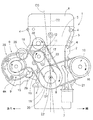
モータジェネレータ9、エアコン用コンプレッサ10、ウォータポンプ11は、それぞれ回転軸に固定されたプーリ15,16,17を備えており、モータジェネレータプーリ15と第1クランクプーリ18とに第1ベルト19が巻き掛けられて、エアコン用コンプレッサ10のプーリ16と第2クランクプーリ20とに第2ベルト21が巻き掛けられて、ウォータポンプ11のプーリ17と第3クランクプーリ22とに第3ベルト23が巻き掛けられている。本実施形態では、モータジェネレータプーリ15が、請求項に記載した補機プーリに相当する。
The
第1クランクプーリ18と第2クランクプーリ20とは略同径であり、モータジェネレータプーリ15は第1クランクプーリ18の略半分の外径になっている。従って、発電機として機能するときは、モータジェネレータ9はクランク軸8の回転数の数倍の回転数で駆動され、モータジェネレータ9がモータとして機能するときは、クランク軸8はモータジェネレータ9の数分の1の回転数で駆動される。
The
第1ベルト19のうちモータジェネレータプーリ15の近くの部位は、振り子式のオートテンショナ28における2個のテンションプーリ29で背面側から挟み込まれている。この場合、オートテンショナ28が機能するには、第1ベルト19がモータジェネレータプーリ15から遠ざかるに従って広がることが必要であり、そこで、第1ベルト19の広がり角度を確保するため、フロントカバー5のうちウォータポンプ11の上側にアイドルプーリ30を取り付けている。従って、ウォータポンプ11は、第1ベルト19で囲われたエリアに配置されている。
A portion of the
モータジェネレータ9は機関本体1の左横に配置しているが、モータジェネレータプーリ15を機関本体1の手前に配置することで、第1ベルト19との間の動力伝達が許容されている。また、オートテンショナ29のテンションプーリ29も、機関本体1の手前に配置されている。更に、第1クランクプーリ18は機関本体1に近い位置に配置しているため、モータジェネレータプーリ15及びテンションプーリ29は、機関本体1の手前に位置しているものの、機関本体1の手前への張り出し寸法はできるだけ小さくなっている。従って、モータジェネレータ9の全体を機関本体1の横に配置できる。
Although the
モータジェネレータ9はクランク軸8よりも上に位置しており、ウォータポンプ11及びアイドルプーリ30は、モータジェネレータ9及び第1クランクプーリ18よりも上に位置している。また、アイドルプーリ30及びウォータポンプ11は、正面視で気筒軸線O2よりもモータジェネレータ9に寄ったエリアに配置されている。
The
図3に示すように、第1クランクプーリ18と第2クランクプーリ20と第3クランクプーリ22とはクランク軸心O1とは一体に形成されており、ボルト32でクランク軸9に固定されている。そして、第1クランクプーリ18が最もフロントカバー5に近くて第3クランクプーリ22がフロントカバー5から最も遠く、第2クランクプーリ20は両者の間に位置している。
As shown in FIG. 3, the
各ベルト19,21,23は、複数の山形リブを有するマルチタイプのVベルトを使用しており、各ベルト19,21,23の溝幅は、第1ベルト19は第2ベルト21よりも幅広で、第2ベルト21は第3ベルト23より幅広になっている。
Each
モータジェネレータ9は、上部と下部との2か所において機関本体1の側面部に取付けられている。上部においては、図2に示すように、モータジェネレータ9のケーシングに設けた左右のリブ33にブラケット34の下部をボルト25で固定し、ブラケット34の上部を、シリンダヘッド3の一側面に突設したボス36にボルト37で固定すると共に、フロントカバー5に設けた横向き張り出し部38にボルト39で固定している。
The
(2).オートテンショナの構成
図4〜6に示すように、オートテンショナ28は、モータジェネレータプーリ15が遊嵌するリング状のベース(本体)41と、テンションプーリ29が回転自在に保持された2つのアーム42とを有しており、2つのアーム42,43を、テンションプーリ29が遠近動し得るように重ねた状態でベース41に装着し、かつ、略U型のばね44で2つのアーム42,43の間隔を保持している。ベース41には、蓋板45を装着している。
(2) Configuration of Auto Tensioner As shown in FIGS. 4 to 6, the
2つのテンションプーリ29は、ばね44と一緒にベース41の軸心回りに回動し得ると共に、ばね44を変形させることで互いに独立して動くことが可能である。ベース41のうちテンションプーリ29と反対側の部位には、複数個(3個)の円筒状足部46を設けており、足部46がモータジェネレータ9の外面にボルト(図示せず)で固定されている。足部46は、図3に一点鎖線で示すトップブラケット板47に固定されている。なお、トップブラケット板47は、リアブラケット板48と補強ロッド49に連結されている。
The two tension pulleys 29 can rotate around the axis of the base 41 together with the
図4に示すように、オートテンショナ28におけるベース41の軸心(アーム42,43の回動中心)50は、クランク軸心方向から見た正面視において、モータジェネレータプーリ15と重なった状態を保持しつつ、モータジェネレータプーリ15の軸心51を挟んで、両テンションプーリ19と反対側に若干の寸法Eだけずれている。換言すると、アーム42,43の回動中心50は、フロントカバー5及びクランク軸8から遠ざかる方向に、モータジェネレータ9におけるプーリ15の軸心51よりも寸法Eだけずれている。
As shown in FIG. 4, the shaft center (the rotation center of the
(3).まとめ
図7において、実線は、機関の運転停止状態及びモータジェネレータ9に負荷が掛かっていない基準状態を示しており、この状態では、2つのテンションプーリ29に作用する第1ベルト19の張力は釣り合っている。
(3) Summary In FIG. 7, the solid lines indicate the engine stop state and the reference state in which no load is applied to the
他方、細かい目の点線は、モータジェネレータ9が発電機として働く場合の状態を示しており、この状態では、第1ベルト19の周回に対してモータジェネレータ9が負荷になるため、第1ベルト19は、モータジェネレータプーリ15とアイドルプーリ30との間での張力が大きくなるため、テンションプーリ29は基準状態よりも上側に移動する。
On the other hand, a fine dotted line indicates a state where the
また、粗い目の点線は、モータジェネレータ9がモータとして働く場合の状態を示しており、この状態では、第1ベルト19がモータジェネレータ9で駆動されるため、第1ベルト19は、モータジェネレータプーリ15と第1クランクプーリ20との間での張力が大きくなって、2つのテンションプーリ29は基準状態よりも下方に移動する。
The rough dotted line indicates a state where the
そして、仮にテンションプーリ29の回動中心50がモータジェネレータプーリ15の回転中心51と同心であると、モータジェネレータ9を機関本体1に寄せるとテンションプーリ29がウォータポンプ11のプーリ17に接近し過ぎてしまうおそれがあるが、回動中心50が回転中心51に対して機関本体1の外側にずれているため、オートテンショナ28のテンションプーリ29とウォータポンプ11のプーリ17との間に必要な間隔を空けつつ、モータジェネレータ9をできるだけ機関本体1に寄せることができる。
If the
従って、内燃機関をできるだけコンパクト化できると共に、モータジェネレータ9の取付け強度を向上できるのである。第1ベルト19のバタ付きを抑制できることと、ミスアライメントの影響を抑制できることは、既に説明したとおりである。
Therefore, the internal combustion engine can be made as compact as possible, and the mounting strength of the
本実施形態では、モータジェネレータ9を機関本体1の横(車両の方向から見ると機関本体1の後ろ)に配置しても、モータジェネレータ9の横(後ろ)に空間を空けることが
できることにより、車両が何かに正面衝突したきに機関本体1が後ろに移動することがあるが、本実施形態では、機関本体1が後ろに移動しても、エンジンルームと車両内部室とを仕切る隔壁とモータジェネレータ9との間の空間をできるだけ大きくできるため、モータジェネレータ9によって隔壁が突き破られたり、後ろに突き出されたりすることを防止又は抑制できる。その結果、衝突時の乗員の安全性を高めることができる。
In the present embodiment, even if the
クランク軸8に3つのクランクプーリ18,20,22を設けて、モータジェネレータ9とエアコン10とウォータポンプ11とを別々のベルト19,21,23で駆動等しているため、各ベルト19,21,23の巾やクランクプーリ18,20,22の外径等は必要な条件に応じて任意に設定できる。このため、各補機は、他の補機の影響を受けることなく適切に駆動等することができる。
Since three crank
更に、最も大きい負荷が掛かる第1ベルト19は機関本体1に最も寄せて配置していることにより、モータジェネレータプーリ15が機関本体1の手前に突出する寸法を最小限度に抑えることができるため、クランク軸8に作用する曲げモーメントやモータジェネレータプーリ15に作用するモーメントをできるだけ抑制できる。その結果、クランク軸8やモータジェネレータ9の回転軸の負担を軽減してその耐久性を向上できる。また、テンションプーリ29も機関本体1に寄せて配置できるため、内燃機関のコンパクト化に一層貢献できることになる。
Further, the
なお、本実施形態では、アイドルプーリ30を気筒軸線O2を挟んだ片側に寄せると共に、モータジェネレータ9も機関本体1の片側の横に寄せており、これにより、モータジェネレータ9を有する動力伝達系をコンパクト化できるが、上下のテンションプーリ29を結ぶ線は、アイドルプーリ30とクランク軸8とを結ぶ線と同じ方向に傾斜しているため、第1ベルト19のうちモータジェネレータプーリ15を挟んだ上下の箇所での張力のバランスを均衡させて、第1ベルト19を適度の曲がり状態に保持できる。この点も、本実施形態の利点の一つである。
In the present embodiment, the
上記の実施形態は、テンションプーリはモータジェネレータ用のベルトに適用されているが、本願発明は、他の補機プーリに巻き掛けたベルトをテンションプーリで挟み込む場合にも適用できる。 In the above embodiment, the tension pulley is applied to a belt for a motor generator, but the present invention can also be applied to a case where a belt wound around another auxiliary pulley is sandwiched between tension pulleys.
本願発明は、車両用内燃機関に具体化できる。従って、産業上利用できる。 The present invention can be embodied in an internal combustion engine for a vehicle. Therefore, it can be used industrially.
1 機関本体
2 機関本体としてのシリンダブロック
3 機関本体としてのシリンダヘッド
9 モータジェネレータ(請求項の補機)
10 エアコン用コンプレッサ
11 ウォータポンプ
15 モータジェネレータプーリ(請求項の補機プーリ)
17 ウォータポンプのプーリ
18 第1クランクプーリ(請求項のクランクプーリ)
19 第1ベルト(請求項のベルト)
28 オートテンショナ
29 テンションプーリ
30 アイドルプーリ
41 ベース
42,43 アーム
44 ばね
50 アームの回動中心
51 補機プーリであるモータジェネレータプーリの軸心
DESCRIPTION OF
10 Compressor for
17 Pulley of
19 First belt (claimed belt)
28
50 Arm rotation center
51 Axis of motor generator pulley, which is an auxiliary pulley
Claims (3)
前記一対のテンションプーリはそれぞれアームに取付けられており、前記両アームは、前記補機プーリの回転軸心と平行な軸心回りに一緒に回動する構成であって、
前記両アームの回動中心を、クランク軸心方向から見て前記補機プーリと重なった状態を保持しつつ、前記補機プーリの軸心を挟んで機関本体と反対側に向いた方向にずらしている、
車両用内燃機関。 A crank pulley fixed to one end of the crankshaft protruding from the front surface of the engine body, an auxiliary pulley that rotates around an axis parallel to the crankshaft, a belt wound around the pulley, and the belt A pair of tension pulleys sandwiching a portion near the auxiliary pulley from the back side of the belt,
Each of the pair of tension pulleys is attached to an arm, and both the arms are configured to rotate together around an axis parallel to a rotation axis of the auxiliary pulley,
The rotation center of both arms is shifted in a direction facing the engine body across the axis of the auxiliary pulley while maintaining the state of overlapping with the auxiliary pulley when viewed from the crank axis direction. ing,
Internal combustion engine for vehicles.
請求項1に記載した車両用内燃機関。 The auxiliary machine is disposed on the left or right outer side of the engine body as viewed from the crank axis direction, while the pair of tension pulleys are located in front of the front surface of the engine body as viewed from the direction orthogonal to the crank axis line. Located in the
The internal combustion engine for a vehicle according to claim 1.
請求項2に記載した車両用内燃機関。 A plurality of crank pulleys offset in the axial direction of the crankshaft are fixed to one end of the crankshaft, and the first belt closest to the engine body among the belts wound around each crank pulley is It is wrapped around an auxiliary machine pulley and sandwiched between the pair of tension pulleys,
An internal combustion engine for a vehicle according to claim 2.
Priority Applications (1)
| Application Number | Priority Date | Filing Date | Title |
|---|---|---|---|
| JP2014111496A JP6355192B2 (en) | 2014-05-29 | 2014-05-29 | Internal combustion engine for vehicle |
Applications Claiming Priority (1)
| Application Number | Priority Date | Filing Date | Title |
|---|---|---|---|
| JP2014111496A JP6355192B2 (en) | 2014-05-29 | 2014-05-29 | Internal combustion engine for vehicle |
Publications (2)
| Publication Number | Publication Date |
|---|---|
| JP2015224613A JP2015224613A (en) | 2015-12-14 |
| JP6355192B2 true JP6355192B2 (en) | 2018-07-11 |
Family
ID=54841566
Family Applications (1)
| Application Number | Title | Priority Date | Filing Date |
|---|---|---|---|
| JP2014111496A Active JP6355192B2 (en) | 2014-05-29 | 2014-05-29 | Internal combustion engine for vehicle |
Country Status (1)
| Country | Link |
|---|---|
| JP (1) | JP6355192B2 (en) |
Families Citing this family (2)
| Publication number | Priority date | Publication date | Assignee | Title |
|---|---|---|---|---|
| JP7200696B2 (en) * | 2019-01-25 | 2023-01-10 | スズキ株式会社 | Mounting structure of auto tensioner for vehicle internal combustion engine |
| WO2022034820A1 (en) * | 2020-08-11 | 2022-02-17 | 三菱自動車工業株式会社 | Belt transmission device |
Family Cites Families (3)
| Publication number | Priority date | Publication date | Assignee | Title |
|---|---|---|---|---|
| EP1437528B1 (en) * | 2003-01-10 | 2010-03-10 | Muhr und Bender KG | Belt tensioner |
| ITTO20030878A1 (en) * | 2003-11-05 | 2005-05-06 | Fiat Ricerche | MOTORCYCLE TRANSMISSION SYSTEM BETWEEN THE CRANKSHAFT OF A MOTOR WITH INTERNAL COMBUSTION OF A MOTOR VEHICLE AND A GROUP OF AUXILIARY DEVICES. |
| WO2005111469A1 (en) * | 2004-05-19 | 2005-11-24 | Dayco Europe S.R.L. Con Unico Socio | Improved pulley for a belt drive of a vehicle |
-
2014
- 2014-05-29 JP JP2014111496A patent/JP6355192B2/en active Active
Also Published As
| Publication number | Publication date |
|---|---|
| JP2015224613A (en) | 2015-12-14 |
Similar Documents
| Publication | Publication Date | Title |
|---|---|---|
| US9850990B2 (en) | Belt tension adjusting device for engine | |
| US20130260932A1 (en) | Tensioner and endless drive arrangement | |
| JP2009530551A (en) | Variable ratio belt transmission system | |
| JP6258749B2 (en) | Internal combustion engine for vehicles | |
| JP6355192B2 (en) | Internal combustion engine for vehicle | |
| JP4544088B2 (en) | Engine front structure | |
| US10626960B2 (en) | Belt connecting structure for vehicle | |
| JP4248204B2 (en) | Belt drive | |
| JP5759344B2 (en) | Auxiliary drive device for internal combustion engine | |
| US10619712B2 (en) | Tensioner mounting structure for vehicle | |
| JP6355193B2 (en) | Internal combustion engine for vehicle | |
| JP2018123709A (en) | Internal combustion engine | |
| JP6813391B2 (en) | Internal combustion engine | |
| JP6270590B2 (en) | Internal combustion engine for vehicles | |
| JP6795427B2 (en) | Internal combustion engine | |
| JP6607067B2 (en) | Auxiliary drive belt tension adjusting device | |
| JP6452191B2 (en) | Internal combustion engine for vehicles | |
| JP6604224B2 (en) | Auxiliary drive belt tension adjusting device | |
| JP2015190449A (en) | internal combustion engine | |
| JP7205095B2 (en) | Mounting structure of tensioner unit for vehicle internal combustion engine | |
| JP6594792B2 (en) | Electronically controlled V-belt type continuously variable transmission | |
| JP6460488B2 (en) | V-type engine supercharger drive mechanism | |
| JPH09280067A (en) | Auxiliary machinery arrangement structure of internal combustion engine | |
| JP4984087B2 (en) | V-type engine accessory drive structure | |
| JP3743454B2 (en) | Cam drive device for internal combustion engine |
Legal Events
| Date | Code | Title | Description |
|---|---|---|---|
| A621 | Written request for application examination |
Free format text: JAPANESE INTERMEDIATE CODE: A621 Effective date: 20170525 |
|
| A977 | Report on retrieval |
Free format text: JAPANESE INTERMEDIATE CODE: A971007 Effective date: 20180315 |
|
| A131 | Notification of reasons for refusal |
Free format text: JAPANESE INTERMEDIATE CODE: A131 Effective date: 20180328 |
|
| A521 | Request for written amendment filed |
Free format text: JAPANESE INTERMEDIATE CODE: A523 Effective date: 20180510 |
|
| TRDD | Decision of grant or rejection written | ||
| A01 | Written decision to grant a patent or to grant a registration (utility model) |
Free format text: JAPANESE INTERMEDIATE CODE: A01 Effective date: 20180606 |
|
| A61 | First payment of annual fees (during grant procedure) |
Free format text: JAPANESE INTERMEDIATE CODE: A61 Effective date: 20180608 |
|
| R150 | Certificate of patent or registration of utility model |
Ref document number: 6355192 Country of ref document: JP Free format text: JAPANESE INTERMEDIATE CODE: R150 |
|
| R250 | Receipt of annual fees |
Free format text: JAPANESE INTERMEDIATE CODE: R250 |
|
| R250 | Receipt of annual fees |
Free format text: JAPANESE INTERMEDIATE CODE: R250 |
|
| R250 | Receipt of annual fees |
Free format text: JAPANESE INTERMEDIATE CODE: R250 |
|
| R250 | Receipt of annual fees |
Free format text: JAPANESE INTERMEDIATE CODE: R250 |