JP6351433B2 - Spool braking device and fishing reel - Google Patents

Spool braking device and fishing reel Download PDF

Info

Publication number
JP6351433B2
JP6351433B2 JP2014162611A JP2014162611A JP6351433B2 JP 6351433 B2 JP6351433 B2 JP 6351433B2 JP 2014162611 A JP2014162611 A JP 2014162611A JP 2014162611 A JP2014162611 A JP 2014162611A JP 6351433 B2 JP6351433 B2 JP 6351433B2
Authority
JP
Japan
Prior art keywords
spool
magnet
conductor
rotation
pole
Prior art date
Legal status (The legal status is an assumption and is not a legal conclusion. Google has not performed a legal analysis and makes no representation as to the accuracy of the status listed.)
Active
Application number
JP2014162611A
Other languages
Japanese (ja)
Other versions
JP2016036308A (en
JP2016036308A5 (en
Inventor
哲史 池袋
哲史 池袋
Current Assignee (The listed assignees may be inaccurate. Google has not performed a legal analysis and makes no representation or warranty as to the accuracy of the list.)
Shimano Inc
Original Assignee
Shimano Inc
Priority date (The priority date is an assumption and is not a legal conclusion. Google has not performed a legal analysis and makes no representation as to the accuracy of the date listed.)
Filing date
Publication date
Application filed by Shimano Inc filed Critical Shimano Inc
Priority to JP2014162611A priority Critical patent/JP6351433B2/en
Priority to KR1020150064612A priority patent/KR102392206B1/en
Priority to TW104118958A priority patent/TWI656838B/en
Priority to US14/813,685 priority patent/US9955678B2/en
Priority to CN201510477855.8A priority patent/CN105360080B/en
Publication of JP2016036308A publication Critical patent/JP2016036308A/en
Publication of JP2016036308A5 publication Critical patent/JP2016036308A5/ja
Application granted granted Critical
Publication of JP6351433B2 publication Critical patent/JP6351433B2/en
Active legal-status Critical Current
Anticipated expiration legal-status Critical

Links

Images

Classifications

    • AHUMAN NECESSITIES
    • A01AGRICULTURE; FORESTRY; ANIMAL HUSBANDRY; HUNTING; TRAPPING; FISHING
    • A01KANIMAL HUSBANDRY; CARE OF BIRDS, FISHES, INSECTS; FISHING; REARING OR BREEDING ANIMALS, NOT OTHERWISE PROVIDED FOR; NEW BREEDS OF ANIMALS
    • A01K89/00Reels
    • A01K89/015Reels with a rotary drum, i.e. with a rotating spool
    • A01K89/0155Antibacklash devices
    • A01K89/01555Antibacklash devices using magnets

Description

本発明は、リール本体に回転自在に支持されたスプールに制動力を付与するスプール制動装置、およびそれを備える魚釣用リールに関する。   The present invention relates to a spool braking device that applies a braking force to a spool that is rotatably supported by a reel body, and a fishing reel that includes the spool braking device.

釣り糸が繰り出されるときに釣り糸が巻かれているスプールが回転する魚釣用リールでは、キャスティング時にスプールの回転速度が糸繰り出し速度より速くなるバックラッシュが生じる場合がある。バックラッシュが生じると、釣り糸がたるむ、いわゆる糸ふけが生じ、糸がらみの原因になる。そこで、回転するスプールに制動力を付与してバックラッシュを防止する制動装置が設けられている。制動装置には一般的に、大別して2つの種類がある。その1つは自由回転するスプールに対し遠心力を利用して摩擦力を作用させるものであり、他の1つは自由回転するスプールに対して磁力を作用させるものである。   In a fishing reel in which a spool around which a fishing line is wound rotates when the fishing line is unwound, backlash in which the rotation speed of the spool becomes faster than the line unwinding speed may occur during casting. When backlash occurs, the fishing line sags, or so-called dandruff, which causes thread sag. Therefore, a braking device is provided that applies a braking force to the rotating spool to prevent backlash. There are generally two types of braking devices. One is to apply a frictional force to the freely rotating spool using centrifugal force, and the other is to apply a magnetic force to the freely rotating spool.

磁力を作用させて、自由回転するスプールに対して制動力を付与する制動装置は、例えば、特許文献1に記載されているように、スプールおよびリール本体のいずれか一方に設けられた導電体と、スプールおよびリール本体のいずれか他方に設けられ、導電体に磁力を作用させることによりスプールの回転を制動する磁石と、スプールの回転速度の増減に応じて磁石が導電体に作用する磁力を増減させ、スプールの回転速度を制御するスプール回転速度制御手段と、スプールの回転速度の増減によりスプール回転速度制御手段が生じさせる制御作用の大きさを調整する制御作用調整手段と、を備える。特許文献1の魚釣用リールでは、スプールの回転速度の増減に応じて導電体および磁石のいずれか一方を他方に対して相対的に移動させることにより、スプールの回転速度に応じて磁石が導電体に作用する磁力を増減させてスプールの回転速度を制御する。これにより、キャスティング開始直後の初期においてスプールの回転速度が比較的大きくなるまでの間は導電体に作用する磁力を減少させてスプールに対する制動力を小さくし、スプールに対する不必要な制動力の負荷をなくすことができる。その結果、スプールからの釣糸の放出速度を高めながら、仕掛けの飛距離を向上させることができる。   A braking device that applies a magnetic force to apply a braking force to a freely rotating spool includes, for example, a conductor provided on one of a spool and a reel body as described in Patent Document 1. A magnet that is provided on either the spool or the reel body and brakes the rotation of the spool by applying a magnetic force to the conductor, and the magnetic force that the magnet acts on the conductor according to the increase or decrease of the rotation speed of the spool. A spool rotation speed control means for controlling the rotation speed of the spool, and a control action adjusting means for adjusting the magnitude of the control action generated by the spool rotation speed control means by increasing or decreasing the rotation speed of the spool. In the fishing reel of Patent Document 1, the magnet is made conductive according to the rotational speed of the spool by moving one of the conductor and the magnet relative to the other according to the increase or decrease of the rotational speed of the spool. The rotational speed of the spool is controlled by increasing or decreasing the magnetic force acting on the body. As a result, the magnetic force acting on the conductor is reduced to reduce the braking force on the spool until the spool rotational speed becomes relatively large at the initial stage immediately after the start of casting, thereby reducing the unnecessary braking force on the spool. Can be eliminated. As a result, the flying distance of the device can be improved while increasing the discharge speed of the fishing line from the spool.

特許文献2には、スプールと連動して回転する導電体と、リール本体に対して軸方向に移動可能、かつ径方向において導電体と対向可能な磁石と、スプールの回転を制動する制動力調整手段と、を備えるスプール制動装置が開示されている。制動力調整手段は、磁石と導電体とが径方向において対向可能な状態で導電体が回転した場合に、導電体に作用する磁石の磁力に基づいて、磁石をリール本体に対して軸方向に移動させることにより、導電体と磁石とが径方向において対向する対向範囲を変化させ、対向範囲の変化により導電体に作用する磁石の磁束数を変化させる。特許文献2のスプール制動装置は、制動力を広範囲で調整できるようにし、スプールの回転に応じた制動力をスプールに適切に付与できるようにしたものである。   Patent Document 2 discloses a conductor that rotates in conjunction with a spool, a magnet that can move in the axial direction relative to the reel body, and that can face the conductor in the radial direction, and a braking force adjustment that brakes the rotation of the spool. And a spool braking device comprising means. The braking force adjusting means moves the magnet in the axial direction relative to the reel body based on the magnetic force of the magnet acting on the conductor when the conductor rotates in a state where the magnet and the conductor can face each other in the radial direction. By moving, the facing range in which the conductor and the magnet face each other in the radial direction is changed, and the number of magnetic fluxes of the magnet acting on the conductor is changed by the change in the facing range. The spool braking device of Patent Document 2 is configured such that the braking force can be adjusted in a wide range, and a braking force according to the rotation of the spool can be appropriately applied to the spool.

特開平10−262518号公報Japanese Patent Laid-Open No. 10-262518 特開2013−236606号公報JP 2013-236606 A

特許文献の技術では、スプール回転速度制御手段(制動力調整手段)は、スプールの回転速度の増減により、導電体もしくは磁石をスプールの回転軸方向に移動させることによって、その磁力による制動力の大きさを調整している。このような制動力調整手段では、導電体もしくは磁石の移動に必要な遠心力を得るために、一定の重量が必要であり、また、移動のための空間も必要となる。そのため、軽量化、小型化の妨げの一因となっており、ひいては、リール自体の軽量化、小型化を妨げる一因となっていた。   In the technique of the patent document, the spool rotation speed control means (braking force adjustment means) moves the conductor or magnet in the direction of the rotation axis of the spool by increasing or decreasing the rotation speed of the spool, thereby increasing the braking force by the magnetic force. It is adjusting. In such a braking force adjusting means, in order to obtain the centrifugal force necessary for the movement of the conductor or the magnet, a certain weight is required, and a space for the movement is also required. For this reason, it has been a factor in hindering weight reduction and size reduction, and in turn has been a factor in hindering weight reduction and size reduction of the reel itself.

本発明は、このような課題を解決するために考案されたものであって、魚釣用リールに用いられるスプール制動装置の軽量化と小型化を図ることを目的とする。   The present invention has been devised to solve such problems, and aims to reduce the weight and size of a spool braking device used in a fishing reel.

本発明の第1の観点に係るスプール制動装置は、リール本体に回転可能に支持されるスプールの回転を制動するスプール制動装置であって、スプールに連動して回転する導電体と、導電体の回転面に向き合う面にN極とS極とを有する磁石と、を備える。そして、導電体の回転によって、導電体に対して磁石の磁気双極子の向きを変化させて、導電体の回転周方向に直交する方向の所定単位幅を有する所定回転面における、磁石が影響する回転周方向の磁束の変化率を変化させる磁束変化率可変機構を備える。 A spool braking device according to a first aspect of the present invention is a spool braking device that brakes rotation of a spool that is rotatably supported by a reel body, and includes a conductor that rotates in conjunction with the spool, A magnet having an N pole and an S pole on a surface facing the rotating surface. Then, by rotating the conductor, the direction of the magnetic dipole of the magnet is changed with respect to the conductor, and the magnet on the predetermined rotation surface having a predetermined unit width in a direction orthogonal to the rotation circumferential direction of the conductor affects. comprising a magnetic flux variation rate varying mechanism for varying the rate of change in the rotational circumferential direction of the magnetic flux.

好ましくは、磁束変化率可変機構は、導電体の移動で磁石によって引き起こされる誘導力の反力で、所定回転面における、導電体の回転周方向の磁束の変化率が大きくなる方向に、磁石を移動させる移動機構を備える。   Preferably, the magnetic flux change rate varying mechanism is configured such that the magnet is moved in a direction in which the rate of change of the magnetic flux in the rotation circumferential direction of the conductor increases on a predetermined rotation surface by a reaction force of the induction force caused by the movement of the conductor. A moving mechanism for moving is provided.

好ましくは、磁束変化率可変機構は、所定回転面における、導電体の回転周方向の磁束の変化率が小さくなる方向に、磁石を移動させる付勢部を備える。   Preferably, the magnetic flux change rate variable mechanism includes an urging unit that moves the magnet in a direction in which the change rate of the magnetic flux in the rotation circumferential direction of the conductor is reduced on a predetermined rotation surface.

好ましくは、磁石は、導電体の磁石に向き合う面に直交する軸の周りに回動可能に支持され、磁束変化率可変機構は、回転面の回転周方向に直交する方向における所定単位幅において、N極とS極とが導電体の回転周方向に並ぶ向きに磁石を回転させる回転機構を備える。 Preferably, the magnet is supported so as to be rotatable about an axis orthogonal to the surface of the conductor facing the magnet, and the magnetic flux change rate varying mechanism is configured to have a predetermined unit width in a direction orthogonal to the rotation circumferential direction of the rotation surface. A rotation mechanism that rotates the magnet in a direction in which the N pole and the S pole are aligned in the rotation circumferential direction of the conductor is provided.

好ましくは、回転機構は、導電体の回転軸の周りに回転可能に支持される回転部材と、磁石を保持し、磁石の導電体に向き合う面の向きを維持しながらN極とS極との中間の周りに回動可能に、回転部材に支持されるカムと、カムに係合し、導電体が回転する周方向の磁石の動きを、カムの回動に変換する係合部材と、を備える。   Preferably, the rotating mechanism includes a rotating member that is rotatably supported around the rotation axis of the conductor, a magnet, and a N-pole and an S-pole while maintaining the orientation of the surface of the magnet facing the conductor. A cam supported by the rotating member so as to be rotatable around the middle, and an engaging member that engages with the cam and converts the movement of the magnet in the circumferential direction in which the conductor rotates into rotation of the cam. Prepare.

回転機構は、導電体の回転軸の周りに回転可能に支持される回転部材と、磁石を保持し、磁石の導電体に向き合う面に向かって周りに外歯を有し、磁石の導電体に向き合う面の向きを維持しながらN極とS極との中間の周りに回動可能に、回転部材に支持されるピニオンと、ピニオンの外歯に噛合する、導電体の回転周方向に一列に形成された平歯を有し、リール本体に固定されたラックと、を備えてもよい。   The rotating mechanism has a rotating member that is rotatably supported around the rotating shaft of the conductor, and a magnet, and has external teeth around a surface facing the conductor of the magnet. The pinion supported by the rotating member and the outer teeth of the pinion mesh with the outer teeth of the pinion so as to be rotatable around the middle of the north and south poles while maintaining the orientation of the facing surfaces. A rack having flat teeth formed and fixed to the reel body.

あるいは、磁石は、導電体の磁石に向き合う面と並行する軸の周りに揺動可能に支持され、磁束変化率可変機構は、回転面の回転周方向に直交する方向おける所定単位幅において、N極とS極の双方が導電体の回転周方向に近接する向きに磁石を揺動させる揺動機構を備えてもよい。 Alternatively, the magnet is swingably supported around an axis parallel to the surface facing the magnet conductor, the magnetic flux variation rate variable mechanism, in a predetermined unit width definitive in the direction perpendicular to the circumferential direction of rotation of the rotating surface, You may provide the rocking | fluctuation mechanism which rocks | fluctuates a magnet in the direction in which both N pole and S pole adjoin to the rotation circumferential direction of a conductor.

好ましくは、2以上の磁石を備え、磁石はそれぞれ、導電体の回転軸を対称軸として回転対称の位置に配置される。   Preferably, two or more magnets are provided, and each of the magnets is disposed at a rotationally symmetric position with respect to the rotational axis of the conductor.

本発明の第2の観点に係る魚釣用リールは、釣り竿に取り付けられるリール本体と、リール本体に回転可能に支持され、釣り糸を外周に巻き取るスプールと、本発明の第1の観点に係るスプール制動装置と、を備える。   A fishing reel according to a second aspect of the present invention relates to a reel main body attached to a fishing rod, a spool that is rotatably supported by the reel main body and winds a fishing line around the outer periphery, and a reel according to the first aspect of the present invention. A spool braking device.

本発明によれば、導電体の回転軸方向の所定単位幅を有する所定回転面における回転周方向の磁束の変化率を、導電体の回転によって変化させるので、導電体および磁石の一方を回転軸の方向に移動させる必要がなく、スプール制動装置の軽量化と小型化を図ることができる。   According to the present invention, the rate of change of the magnetic flux in the rotation circumferential direction on the predetermined rotation surface having the predetermined unit width in the rotation axis direction of the conductor is changed by the rotation of the conductor. Therefore, the spool brake device can be reduced in weight and size.

本発明の実施の形態1に係る魚釣用リールの斜視図である。It is a perspective view of the fishing reel which concerns on Embodiment 1 of this invention. 実施の形態1に係る魚釣用リールの断面図である。1 is a cross-sectional view of a fishing reel according to Embodiment 1. FIG. 実施の形態1に係るスプール制動装置の断面図である。1 is a cross-sectional view of a spool braking device according to Embodiment 1. FIG. 実施の形態1に係るスプール制動装置の分解斜視図である。1 is an exploded perspective view of a spool braking device according to Embodiment 1. FIG. 実施の形態1に係るスプール制動装置の動作を示す図である。FIG. 5 is a diagram illustrating an operation of the spool braking device according to the first embodiment. 実施の形態1に係るスプール制動装置の停止状態における磁束を示す概念図である。It is a conceptual diagram which shows the magnetic flux in the stop state of the spool braking device which concerns on Embodiment 1. FIG. 実施の形態1に係るスプール制動装置の最大制動状態における磁束を示す概念図である。It is a conceptual diagram which shows the magnetic flux in the maximum braking state of the spool braking device which concerns on Embodiment 1. FIG. 実施の形態1の変形例に係るスプール制動装置の動作を示す概念図である。FIG. 10 is a conceptual diagram showing an operation of a spool braking device according to a modification of the first embodiment. 本発明の実施の形態2に係るスプール制動装置の断面図である。It is sectional drawing of the spool braking device which concerns on Embodiment 2 of this invention. 実施の形態2に係るスプール制動装置を回転軸の方向に見た断面図である。It is sectional drawing which looked at the spool braking device which concerns on Embodiment 2 in the direction of the rotating shaft. 実施の形態2に係るスプール制動装置の動作を示す図である。FIG. 10 is a diagram illustrating an operation of a spool braking device according to a second embodiment. 実施の形態2に係るスプール制動装置の作用を示す概念図である。It is a conceptual diagram which shows the effect | action of the spool braking device which concerns on Embodiment 2. FIG. 実施の形態2に係るスプール制動装置の停止状態における磁束を示す概念図である。It is a conceptual diagram which shows the magnetic flux in the stop state of the spool braking device which concerns on Embodiment 2. FIG. 実施の形態2に係るスプール制動装置の制動状態における磁束を示す概念図である。It is a conceptual diagram which shows the magnetic flux in the braking state of the spool braking device which concerns on Embodiment 2. FIG.

[実施の形態1]
図1は、本発明の実施の形態1に係る魚釣用リールの斜視図である。この魚釣用リールは、主にルアーフィッシングに用いられる両軸受リールである。この両軸受リールは、リール本体1と、リール本体1の側方に配置されたハンドル2と、ハンドル2のリール本体1側に配置されたドラグ調整用のスタードラグ3と、を備えている。リール本体1には、釣り糸が巻かれるスプール12が回転可能に支持されている。ハンドル2を回すとスプール12を回転させて、釣り糸を巻き取ることができる。ハンドル2は、板状のアーム部2aと、アーム部2aの両端に回転自在に装着された1対の把手2bとを、有している。
[Embodiment 1]
FIG. 1 is a perspective view of a fishing reel according to Embodiment 1 of the present invention. This fishing reel is a double-bearing reel mainly used for lure fishing. The dual-bearing reel includes a reel body 1, a handle 2 disposed on the side of the reel body 1, and a drag drag adjusting star drag 3 disposed on the reel body 1 side of the handle 2. A spool 12 around which fishing line is wound is rotatably supported on the reel body 1. When the handle 2 is turned, the spool 12 can be rotated to wind up the fishing line. The handle 2 includes a plate-like arm portion 2a and a pair of grips 2b that are rotatably attached to both ends of the arm portion 2a.

釣り糸は通常スプール12から、図1に向かって左手前側に張られている。図1で左手前側をリール本体1の前方、右手奥側を後方という。リール本体1の後方にクラッチ操作レバー17が配置されている。クラッチ操作レバー17を操作すると、ハンドル2とスプール12の間のクラッチを切ることができる。スプール12の前方側を取り巻くようにサムレスト10が装着されている。   The fishing line is usually stretched from the spool 12 toward the left front side in FIG. In FIG. 1, the left front side is referred to as the front side of the reel body 1, and the right hand back side is referred to as the rear side. A clutch operation lever 17 is disposed behind the reel body 1. When the clutch operating lever 17 is operated, the clutch between the handle 2 and the spool 12 can be disconnected. A thumb rest 10 is mounted so as to surround the front side of the spool 12.

キャスティング動作によってスプール12に巻かれた釣り糸が繰り出されるとスプール12が回転する。キャスティング動作時のバックラッシュを防止するために、リール本体1の内部にスプール制動装置20が備えられている。リール本体1のハンドル2とは反対側の側面に、そのスプール制動装置20の制動力を調節する操作つまみ65が配置されている。操作つまみ65を回すことによって、スプール12の制動力を調節することができる。   When the fishing line wound around the spool 12 is fed out by the casting operation, the spool 12 rotates. In order to prevent backlash during the casting operation, a spool braking device 20 is provided inside the reel body 1. An operation knob 65 for adjusting the braking force of the spool braking device 20 is disposed on the side surface of the reel body 1 opposite to the handle 2. By turning the operation knob 65, the braking force of the spool 12 can be adjusted.

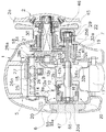
図2は、実施の形態1に係る魚釣用リールの断面図である。図2を文字が正立する向きに見て上が前方、下が後方である。リール本体1は、フレーム5と、フレーム5の両側方に装着された第1側カバー6および第2側カバー7と、を有している。サムレスト10(図1参照)はフレーム5の上部に装着される。フレーム5は、所定の間隔を開けて互いに対向するように配置された1対の第1側板8および第2側板9と、これらの第1側板8および第2側板9を連結する図示しない複数の連結部とを有している。   FIG. 2 is a cross-sectional view of the fishing reel according to the first embodiment. When FIG. 2 is viewed in the direction in which the characters stand upright, the top is the front and the bottom is the back. The reel body 1 includes a frame 5, and a first side cover 6 and a second side cover 7 mounted on both sides of the frame 5. The thumb rest 10 (see FIG. 1) is attached to the upper part of the frame 5. The frame 5 includes a pair of first side plate 8 and second side plate 9 arranged so as to face each other with a predetermined gap therebetween, and a plurality of unillustrated links that connect the first side plate 8 and the second side plate 9. And a connecting portion.

ハンドル2側の第2側カバー7は、ねじにより第2側板9に着脱自在に固定されている。ハンドル2と逆側の第1側板8には、スプール12が通過可能な開口8aが、形成されている。ハンドル2と逆側の第1側カバー6には、ブレーキケース55が、ねじにより固定されている。   The second side cover 7 on the handle 2 side is detachably fixed to the second side plate 9 with screws. An opening 8a through which the spool 12 can pass is formed in the first side plate 8 opposite to the handle 2. A brake case 55 is fixed to the first side cover 6 opposite to the handle 2 with screws.

フレーム5内には、スプール12と、レベルワインド機構15と、クラッチ操作レバー17と、が配置されている。レベルワインド機構15は、スプール12に釣り糸を均一に巻き付けるための機構である。クラッチ操作レバー17は、サミングを行う場合の親指の当てとなる。   A spool 12, a level wind mechanism 15, and a clutch operation lever 17 are disposed in the frame 5. The level wind mechanism 15 is a mechanism for uniformly winding the fishing line around the spool 12. The clutch operating lever 17 serves as a thumb rest for summing.

フレーム5の第2側板9と第2側カバー7との間には、ギア機構18と、クラッチ機構13と、クラッチ係脱機構19と、ドラグ機構21と、キャスティングコントロール機構22と、が、配置されている。ギア機構18は、ハンドル2からの回転力を、スプール12およびレベルワインド機構15に伝える。クラッチ係脱機構19は、クラッチ操作レバー17の操作に応じて、クラッチ機構13の係脱を行う。ドラグ機構21は、糸繰り出し時にスプール12を制動する。キャスティングコントロール機構22は、スプール軸16を両端で挟んで制動する。また、開口8aには、キャスティング時のバックラッシュを抑えるためのスプール制動装置20が、配置されている。   A gear mechanism 18, a clutch mechanism 13, a clutch engagement / disengagement mechanism 19, a drag mechanism 21, and a casting control mechanism 22 are arranged between the second side plate 9 and the second side cover 7 of the frame 5. Has been. The gear mechanism 18 transmits the rotational force from the handle 2 to the spool 12 and the level wind mechanism 15. The clutch engagement / disengagement mechanism 19 engages / disengages the clutch mechanism 13 in accordance with the operation of the clutch operation lever 17. The drag mechanism 21 brakes the spool 12 when the yarn is fed. The casting control mechanism 22 brakes with the spool shaft 16 sandwiched between both ends. A spool braking device 20 for suppressing backlash during casting is disposed in the opening 8a.

スプール12は、例えばアルミニウム合金製であり、非磁性の電気的導電体である。スプール12は、スプール12に連動して回転する導電体ともいえる。スプール12は、筒状の糸巻胴部12bとその両端に連続する両側部に皿状のフランジ部12aを有している。スプール12は、糸巻胴部12bの内周側に一体に形成された筒状のボス部12cを、有している。スプール12は、ボス部12cを貫通するスプール軸16に相対回転しないように、例えばセレーション結合により固定されている。   The spool 12 is made of, for example, an aluminum alloy and is a nonmagnetic electric conductor. The spool 12 can be said to be a conductor that rotates in conjunction with the spool 12. The spool 12 has a cylindrical bobbin trunk 12b and dish-shaped flanges 12a on both sides continuous to both ends thereof. The spool 12 has a cylindrical boss portion 12c integrally formed on the inner peripheral side of the bobbin trunk 12b. The spool 12 is fixed by, for example, serration coupling so as not to rotate relative to the spool shaft 16 penetrating the boss portion 12c.

スプール軸16は、第2側板9を貫通して第2側カバー7の外方に延びている。スプール軸16のハンドル2に近い端は、第2側カバー7に形成されたボス部29に対して回転自在に、軸受35bで支持されている。スプール軸16の第1側カバー6に近い端は、ブレーキケース55の内筒部55a内で、軸受35aにより回転自在に支持されている。   The spool shaft 16 extends through the second side plate 9 to the outside of the second side cover 7. The end of the spool shaft 16 near the handle 2 is supported by a bearing 35b so as to be rotatable with respect to a boss portion 29 formed on the second side cover 7. The end of the spool shaft 16 close to the first side cover 6 is rotatably supported by the bearing 35a in the inner cylinder portion 55a of the brake case 55.

レベルワインド機構15は、第1側板8および第2側板9の間に固定されたガイド筒25と、ガイド筒25内に回転自在に配置された螺軸26と、ラインガイド27とを有している。螺軸26の端部には、ギア機構18を構成するギア28aが固定されている。螺軸26には、螺旋状溝26aが形成されている。この螺旋状溝26aには、ラインガイド27が噛み合っている。ギア機構18を介して螺軸26が回転させられることにより、ラインガイド27は、ガイド筒25に沿って往復移動する。このラインガイド27内に釣り糸が挿通される。螺軸26はスプール軸16と同期して回転するので、釣り糸がスプール12に均一に巻き付けられる。   The level wind mechanism 15 includes a guide tube 25 fixed between the first side plate 8 and the second side plate 9, a screw shaft 26 rotatably disposed in the guide tube 25, and a line guide 27. Yes. A gear 28 a constituting the gear mechanism 18 is fixed to the end of the screw shaft 26. A spiral groove 26 a is formed in the screw shaft 26. A line guide 27 is engaged with the spiral groove 26a. The line guide 27 reciprocates along the guide cylinder 25 by rotating the screw shaft 26 via the gear mechanism 18. A fishing line is inserted into the line guide 27. Since the screw shaft 26 rotates in synchronization with the spool shaft 16, the fishing line is uniformly wound around the spool 12.

ギア機構18は、ギア28aと、ギア28aに噛み合うギア28bと、ドライブギア31と、ドライブギア31に噛み合う筒状のピニオンギア32とから構成される。ギア28aは前述の螺軸26端部に固定され、ギア28aに噛み合うギア28bはハンドル軸30に相対回転しないように固定される。ハンドル軸30の回転は、ギア28bおよびギア28aで螺軸26に伝達される。ドライブギア31は、ハンドル軸30に回転自在に装着され、ハンドル軸30の回転がドラグ機構21を介して伝達される。   The gear mechanism 18 includes a gear 28 a, a gear 28 b that meshes with the gear 28 a, a drive gear 31, and a cylindrical pinion gear 32 that meshes with the drive gear 31. The gear 28a is fixed to the end portion of the screw shaft 26, and the gear 28b meshing with the gear 28a is fixed so as not to rotate relative to the handle shaft 30. The rotation of the handle shaft 30 is transmitted to the screw shaft 26 by the gear 28b and the gear 28a. The drive gear 31 is rotatably mounted on the handle shaft 30, and the rotation of the handle shaft 30 is transmitted via the drag mechanism 21.

ピニオンギア32は、第2側板9を貫通して配置されている。ピニオンギア32は、筒状部材である。ピニオンギア32の中心には、スプール軸16が挿通される。ピニオンギア32は、スプール軸16に軸方向に移動自在に装着されている。ピニオンギア32は、図2右端部外周に形成されドライブギア31に噛み合う歯部32aと、他端側に形成された噛み合い部32bとを、有している。歯部32aと噛み合い部32bとの間には、くびれ部32cが設けられている。   The pinion gear 32 is disposed through the second side plate 9. The pinion gear 32 is a cylindrical member. The spool shaft 16 is inserted through the center of the pinion gear 32. The pinion gear 32 is attached to the spool shaft 16 so as to be movable in the axial direction. The pinion gear 32 has a tooth portion 32a formed on the outer periphery of the right end portion in FIG. 2 and meshing with the drive gear 31, and a meshing portion 32b formed on the other end side. A constricted portion 32c is provided between the tooth portion 32a and the meshing portion 32b.

噛み合い部32bは、ピニオンギア32の端面に形成された凹溝から構成されている。この凹溝には、スプール軸16を径方向に貫通するクラッチピン16aが嵌まり込んで係合する。ピニオンギア32がハンドル2の方に移動すると、噛み合い部32bの凹溝とスプール軸16のクラッチピン16aとが離脱して係合が解除され、ピニオンギア32の回転はスプール12に伝達されなくなる。この噛み合い部32bの凹溝とクラッチピン16aとにより、クラッチ機構13が構成される。   The meshing portion 32 b is configured by a concave groove formed on the end surface of the pinion gear 32. A clutch pin 16a that penetrates the spool shaft 16 in the radial direction is fitted into and engaged with the concave groove. When the pinion gear 32 moves toward the handle 2, the concave groove of the meshing portion 32b and the clutch pin 16a of the spool shaft 16 are disengaged and the engagement is released, and the rotation of the pinion gear 32 is not transmitted to the spool 12. The clutch mechanism 13 is configured by the concave groove of the meshing portion 32b and the clutch pin 16a.

クラッチ操作レバー17は、1対の第1側板8および第2側板9の間で、スプール12の後方に配置されている。クラッチ係脱機構19は、クラッチヨーク40とクラッチ操作レバー17に固定される図示しないクラッチカムを有している。クラッチ係脱機構19は、クラッチ操作レバー17の回動により、図示しないクラッチカムを介してクラッチヨーク40をスプール軸の軸芯と平行に移動させる。また、クラッチ係脱機構19は、ハンドル軸30が糸巻き取り方向に回転すると、クラッチ機構13が自動的につながるように、クラッチヨーク40を移動させる。   The clutch operating lever 17 is disposed behind the spool 12 between the pair of the first side plate 8 and the second side plate 9. The clutch engagement / disengagement mechanism 19 has a clutch cam (not shown) fixed to the clutch yoke 40 and the clutch operation lever 17. The clutch engagement / disengagement mechanism 19 moves the clutch yoke 40 in parallel with the axis of the spool shaft via a clutch cam (not shown) as the clutch operation lever 17 rotates. The clutch engagement / disengagement mechanism 19 moves the clutch yoke 40 so that the clutch mechanism 13 is automatically connected when the handle shaft 30 rotates in the yarn winding direction.

釣り糸を巻き取ることができる通常状態では、ピニオンギア32はスプール12側のクラッチ係合位置に位置している。このクラッチ係合位置において、ピニオンギア32の噛み合い部32bとスプール軸16のクラッチピン16aとが係合して、クラッチをつないだ状態となっている。クラッチヨーク40によってピニオンギア32がハンドル2側に移動されると、噛み合い部32bとクラッチピン16aとの係合が外れ、クラッチを切った状態となる。   In a normal state where the fishing line can be taken up, the pinion gear 32 is located at the clutch engagement position on the spool 12 side. At this clutch engagement position, the meshing portion 32b of the pinion gear 32 and the clutch pin 16a of the spool shaft 16 are engaged and the clutch is engaged. When the pinion gear 32 is moved to the handle 2 side by the clutch yoke 40, the engagement portion 32b and the clutch pin 16a are disengaged and the clutch is disengaged.

キャスティングコントロール機構22は、有底筒状のキャップ45と、キャップ45の底部に装着された摩擦プレート46と、ブレーキケース55に装着された摩擦プレート47とを備えている。キャップ45は、第2側カバー7のボス部29の外周側に形成された雄ネジ部に螺合する。摩擦プレート46および摩擦プレート47はそれぞれ、スプール軸16の端に接触して、スプール軸16を挟持する。例えば、キャップ45が回転された場合、摩擦プレート46および摩擦プレート47によって発生する挟持力が調整される。これにより、スプール12の制動力が調整される。   The casting control mechanism 22 includes a bottomed cylindrical cap 45, a friction plate 46 attached to the bottom of the cap 45, and a friction plate 47 attached to the brake case 55. The cap 45 is screwed into a male screw portion formed on the outer peripheral side of the boss portion 29 of the second side cover 7. Each of the friction plate 46 and the friction plate 47 comes into contact with the end of the spool shaft 16 and clamps the spool shaft 16. For example, when the cap 45 is rotated, the clamping force generated by the friction plate 46 and the friction plate 47 is adjusted. Thereby, the braking force of the spool 12 is adjusted.

図3は、実施の形態1に係るスプール制動装置の断面図である。ブレーキケース55は、有底筒状の部材である。ブレーキケース55は、外周部が第1側板8の開口8aにバヨネット構造14によって装着される。ブレーキケース55のスプール12側の中央部には、筒状に突出する内筒部55aが形成されている。内筒部55aの外周部には、スプール制動装置20の筒部60が装着される。内筒部55aの内周部は、軸受35aの外輪を支持している。内筒部55aの基端部外周部には、複数の貫通孔55bが形成されている。貫通孔55bには、操作つまみ65の押圧部65bが挿通される。   FIG. 3 is a cross-sectional view of the spool braking device according to the first embodiment. The brake case 55 is a bottomed cylindrical member. The outer periphery of the brake case 55 is attached to the opening 8 a of the first side plate 8 by the bayonet structure 14. An inner cylinder portion 55 a that protrudes in a cylindrical shape is formed at the center portion of the brake case 55 on the spool 12 side. A cylindrical portion 60 of the spool braking device 20 is attached to the outer peripheral portion of the inner cylindrical portion 55a. The inner peripheral part of the inner cylinder part 55a supports the outer ring of the bearing 35a. A plurality of through holes 55b are formed in the outer peripheral portion of the base end portion of the inner cylinder portion 55a. The pressing portion 65b of the operation knob 65 is inserted into the through hole 55b.

操作つまみ65は、図1に示されるように円形のつまみ部65aと、複数の押圧部65bとを有している。つまみ部65aは、第1側カバー6に形成された開口6aから露出する部分である。複数の押圧部65bは、つまみ部65aのスプール12側に突出して設けられている。押圧部65bは、貫通孔55bに挿通され、スプール制動装置20の筒部60を押圧可能に筒部60の底面に当接している。以下、スプール制動装置20の構成を説明する。   As shown in FIG. 1, the operation knob 65 includes a circular knob portion 65a and a plurality of pressing portions 65b. The knob portion 65 a is a portion exposed from the opening 6 a formed in the first side cover 6. The plurality of pressing portions 65b are provided to protrude toward the spool 12 of the knob portion 65a. The pressing portion 65b is inserted into the through hole 55b, and abuts the bottom surface of the cylindrical portion 60 so as to be able to press the cylindrical portion 60 of the spool braking device 20. Hereinafter, the configuration of the spool braking device 20 will be described.

スプール制動装置20は、筒部60、磁石51、保持部材61、支持リング62および係合部材63を有する。筒部60は、その中心軸がスプール軸16の中心軸と一致するように配置される。図2および図3では、内筒部55aの上下でスプール制動装置20の異なる部分の断面が示されている。内筒部55aの上側(レベルワインド機構15側)では磁石51のある部分の断面を、下側(クラッチ操作レバー17側)では磁石51のない部分の断面を示す。   The spool braking device 20 includes a cylindrical portion 60, a magnet 51, a holding member 61, a support ring 62, and an engaging member 63. The cylindrical portion 60 is disposed such that the central axis thereof coincides with the central axis of the spool shaft 16. 2 and 3 show different sections of the spool braking device 20 above and below the inner cylinder portion 55a. The cross section of the part with the magnet 51 is shown on the upper side (level wind mechanism 15 side) of the inner cylinder part 55a, and the cross section of the part without the magnet 51 is shown on the lower side (clutch operation lever 17 side).

図4は、実施の形態1に係るスプール制動装置の分解斜視図である。支持リング62は、筒部60の内周底部に配置される。支持リング62は筒部の内周底部からスプール軸16の軸方向に移動しないように、例えばピン64(図3参照)で規制されている。図4では、支持リング62を軸方向に規制する部材が省略されている。支持リング62は筒部60に対して軸方向には移動しないが、中心軸の回りに回転可能である。支持リング62には、保持部材61の数だけ回転対称の位置でかつ等間隔に孔62aが形成されている。   FIG. 4 is an exploded perspective view of the spool braking device according to the first embodiment. The support ring 62 is disposed on the inner peripheral bottom portion of the cylindrical portion 60. The support ring 62 is regulated by, for example, a pin 64 (see FIG. 3) so as not to move in the axial direction of the spool shaft 16 from the inner peripheral bottom portion of the cylindrical portion. In FIG. 4, a member for restricting the support ring 62 in the axial direction is omitted. The support ring 62 does not move in the axial direction with respect to the cylindrical portion 60, but can rotate around the central axis. Holes 62 a are formed in the support ring 62 at positions that are rotationally symmetric and equally spaced by the number of the holding members 61.

磁石51は保持部材61にはめ込まれて固定され、磁石51と保持部材61は一体になっている。磁石51はスプール12の回転面に向き合う面にN極とS極とを有する。回転面はこの場合、スプール12の糸巻胴部12bの内周面である。磁石51を保持する保持部材61は、筒部60の側面に形成された案内孔60aに収容される。保持部材61には、支持部61aと係合部61bが形成されている。支持部61aは、支持リング62の孔62aに嵌合し、保持部材61は支持リング62に対して回動可能に支持される。支持リング62が筒部60に対して回転しながら、保持部材61を回動可能に支持するように、支持リング62の孔62aの周囲は平面になっている。   The magnet 51 is fitted and fixed to the holding member 61, and the magnet 51 and the holding member 61 are integrated. The magnet 51 has an N pole and an S pole on the surface facing the rotation surface of the spool 12. In this case, the rotating surface is the inner peripheral surface of the bobbin trunk 12b of the spool 12. The holding member 61 that holds the magnet 51 is accommodated in a guide hole 60 a formed on the side surface of the cylindrical portion 60. The holding member 61 is formed with a support portion 61a and an engaging portion 61b. The support portion 61 a is fitted into the hole 62 a of the support ring 62, and the holding member 61 is supported to be rotatable with respect to the support ring 62. The periphery of the hole 62a of the support ring 62 is a flat surface so that the holding member 61 is rotatably supported while the support ring 62 rotates with respect to the cylindrical portion 60.

保持部材61の係合部61bは、係合部材63の係合孔63aにはめ込まれる。係合部61bと係合孔63aには遊びがあり、係合部61bは係合孔63aの中で自由に回転できる。係合部材63は、筒部60に収容される。係合部材63は筒部60に対して、軸方向には移動するが、回転できないように支持される。例えば、係合部材63の外周の面取りされた平面部分が、筒部60の内周面に形成された平面部分に対向するようにはめ込まれて、筒部60に対して係合部材63が回転できないように規制される。   The engaging portion 61 b of the holding member 61 is fitted into the engaging hole 63 a of the engaging member 63. There is play in the engaging portion 61b and the engaging hole 63a, and the engaging portion 61b can freely rotate in the engaging hole 63a. The engaging member 63 is accommodated in the cylindrical portion 60. The engaging member 63 moves in the axial direction with respect to the cylindrical portion 60, but is supported so as not to rotate. For example, the chamfered flat portion of the outer periphery of the engaging member 63 is fitted so as to face the flat portion formed on the inner peripheral surface of the cylindrical portion 60, and the engaging member 63 rotates with respect to the cylindrical portion 60. It is regulated so that it cannot.

筒部60の内周底面と係合部材63の間には図示しない押圧バネが配置され、係合部材63を筒部60から飛び出る方向に付勢する。係合部材63の係合孔63aは保持部材61の係合部61bに係合し、保持部材61は筒部60の案内孔60aに収容され、かつ、保持部材61の支持部61aは支持リング62の孔62aに嵌合されている。そして、支持リング62は筒部60に対して軸方向に移動しないように規制されているので、係合部材63は押圧バネで付勢されても、筒部60から抜け出ることはない。この状態で保持部材61は、支持部61aと係合部61bを結ぶ線が筒部60の軸方向になるように付勢される。   A pressing spring (not shown) is disposed between the inner peripheral bottom surface of the cylindrical portion 60 and the engaging member 63, and urges the engaging member 63 in the direction of protruding from the cylindrical portion 60. The engaging hole 63a of the engaging member 63 engages with the engaging portion 61b of the holding member 61, the holding member 61 is accommodated in the guide hole 60a of the cylindrical portion 60, and the support portion 61a of the holding member 61 is a support ring. 62 is fitted in the hole 62a. Since the support ring 62 is regulated so as not to move in the axial direction with respect to the cylindrical portion 60, the engaging member 63 does not come out of the cylindrical portion 60 even when urged by the pressing spring. In this state, the holding member 61 is urged so that a line connecting the support portion 61 a and the engagement portion 61 b is in the axial direction of the cylindrical portion 60.

スプール制動装置20を組み立てるには、例えば、以下のようにする。筒部60の内周底面に支持リング62を配置し、支持リング62が抜け出ないように、例えば図3のピン64で規制する。押圧バネを筒部60の内周底面と係合部材63で挟みながら、係合部材63を筒部60に押し込む。支持リング62の孔62aと係合部材63の係合孔63aが、筒部60の案内孔60aから見える位置で、保持部材61の支持部61aと係合部61bの距離になるように保持し、磁石51を保持する保持部材61を案内孔60aから挿入し、支持部61aを支持リング62の孔62aに、係合部61bを係合孔63aにはめ込む。すべての保持部材61を同様にはめ込んで、組み立てを完了する。   For example, the spool braking device 20 is assembled as follows. A support ring 62 is disposed on the inner peripheral bottom surface of the cylindrical portion 60, and is regulated by, for example, a pin 64 in FIG. The engaging member 63 is pushed into the cylindrical portion 60 while the pressing spring is sandwiched between the inner peripheral bottom surface of the cylindrical portion 60 and the engaging member 63. The hole 62a of the support ring 62 and the engagement hole 63a of the engagement member 63 are held so that the distance between the support portion 61a and the engagement portion 61b of the holding member 61 is at a position where it can be seen from the guide hole 60a of the cylindrical portion 60. The holding member 61 that holds the magnet 51 is inserted from the guide hole 60a, and the support portion 61a is inserted into the hole 62a of the support ring 62, and the engagement portion 61b is inserted into the engagement hole 63a. All the holding members 61 are fitted in the same manner to complete the assembly.

図5は、実施の形態1に係るスプール制動装置の動作を示す図である。図5は、筒部60の案内孔60aの部分を外周面から中心軸の方向に見たものである。図5では、スプール12の軸方向が上下であり、スプール12の回転する周方向が左右である。実線で表された保持部材61および磁石51は、スプール12が回転していない状態を示す。二点鎖線で表された保持部材61および磁石51はスプール12が回転している状態を示す。筒部60は円筒面なので、案内孔60aの両側の側面が見えている。釣り糸をキャストしたときに、スプール12の磁石51に対向する面が図5の左方向に移動するようにスプール12が回転する。   FIG. 5 is a diagram illustrating the operation of the spool braking device according to the first embodiment. FIG. 5 shows the guide hole 60a portion of the cylindrical portion 60 as viewed from the outer peripheral surface in the direction of the central axis. In FIG. 5, the axial direction of the spool 12 is up and down, and the circumferential direction in which the spool 12 rotates is left and right. A holding member 61 and a magnet 51 represented by a solid line indicate a state where the spool 12 is not rotating. A holding member 61 and a magnet 51 represented by a two-dot chain line indicate a state in which the spool 12 is rotating. Since the cylindrical part 60 is a cylindrical surface, the side surfaces on both sides of the guide hole 60a are visible. When the fishing line is cast, the spool 12 rotates so that the surface of the spool 12 that faces the magnet 51 moves to the left in FIG.

スプール12が回転していない状態では、保持部材61は、係合部材63を介して押圧バネで支持部61aと係合部61bを結ぶ線が筒部60の軸方向になるように付勢される。その状態で、磁石51はN極とS極がスプール12の軸方向に並ぶ向きに配置されている。このとき、スプール12の回転面の一部を周方向にみると、対向する1つの磁石51の磁極はN極またはS極だけである。   In a state where the spool 12 is not rotating, the holding member 61 is urged by a pressing spring via the engagement member 63 so that a line connecting the support portion 61a and the engagement portion 61b is in the axial direction of the cylindrical portion 60. The In this state, the magnet 51 is arranged so that the N pole and the S pole are aligned in the axial direction of the spool 12. At this time, when a part of the rotating surface of the spool 12 is viewed in the circumferential direction, the magnetic poles of the one magnet 51 facing each other are only the N pole or the S pole.

スプール12が回転すると、スプール12の回転面に対向する磁石51の磁束によって、スプール12にはその回転速度に応じた渦電流が発生する。この渦電流によってスプール12には回転方向と逆方向の誘導力がかかる。これにより、スプール12は制動される。スプール12の回転(スプール面の移動)で磁石51によって引き起こされる誘導力の反力で、逆に磁石51はスプール12の回転する方向に引きずられる。磁石51を保持する保持部材61は、支持部61aで支持リング62に回動可能に支持され、係合部61bが軸方向にしか移動しないように係合部材63で規制されている。そして支持リング62は軸の回りに回転するが軸方向には移動しない。また、案内孔60aの突出部60bで係合部61bの基部が抑えられるので、保持部材61は図5の左に移動しながら時計回りに回転する。その結果磁石51は、N極とS極がスプール12の回転する周方向に並ぶ向きに回転しながら移動させられる。このとき、スプール12の回転面の一部を周方向に見ると、対向する1つの磁石51の磁極はN極とS極が並んでいる。   When the spool 12 rotates, an eddy current corresponding to the rotation speed is generated in the spool 12 by the magnetic flux of the magnet 51 facing the rotation surface of the spool 12. Due to the eddy current, an induction force in the direction opposite to the rotation direction is applied to the spool 12. Thereby, the spool 12 is braked. On the contrary, the magnet 51 is dragged in the direction in which the spool 12 rotates due to the reaction force of the induction force caused by the rotation of the spool 12 (movement of the spool surface). The holding member 61 that holds the magnet 51 is rotatably supported by the support ring 62 by the support portion 61a, and is restricted by the engagement member 63 so that the engagement portion 61b moves only in the axial direction. The support ring 62 rotates around the axis but does not move in the axial direction. Moreover, since the base part of the engaging part 61b is restrained by the protrusion part 60b of the guide hole 60a, the holding member 61 rotates clockwise while moving to the left in FIG. As a result, the magnet 51 is moved while rotating in a direction in which the N pole and the S pole are aligned in the circumferential direction in which the spool 12 rotates. At this time, when a part of the rotating surface of the spool 12 is viewed in the circumferential direction, the magnetic poles of one opposing magnet 51 are arranged with N and S poles.

図6Aは、実施の形態1に係るスプール制動装置の停止状態における磁束を示す概念図である。図6Aの白抜き矢印は、スプール12の回転する方向を示す。それぞれの磁石51のN極とS極はスプール12の回転軸の方向に並んでいる。磁石51に対向するスプール12の一点を通る回転面(円)について見れば、対向する磁石51の磁極はN極またはS極だけである。1つの磁極の大きさより十分小さい微小幅の回転面における磁束は、図6Aの上のグラフのように表すことができる。N極またはS極だけの磁束なので、グラフは回転周方向を示す磁束基準線の片側だけに表されている。   FIG. 6A is a conceptual diagram showing a magnetic flux in a stopped state of the spool braking device according to the first embodiment. The white arrow in FIG. 6A indicates the direction in which the spool 12 rotates. The N pole and S pole of each magnet 51 are aligned in the direction of the rotation axis of the spool 12. If it sees about the rotation surface (circle) which passes along one point of the spool 12 which opposes the magnet 51, the magnetic pole of the magnet 51 which opposes is only N pole or S pole. The magnetic flux on the rotating surface having a minute width sufficiently smaller than the size of one magnetic pole can be expressed as shown in the upper graph of FIG. 6A. Since the magnetic flux is only N-pole or S-pole, the graph is shown only on one side of the magnetic flux reference line indicating the rotational circumferential direction.

図6Bは、実施の形態1に係るスプール制動装置の最大制動状態における磁束を示す概念図である。それぞれの磁石51のN極とS極はスプール12の回転する周方向に並んでいる。磁石51に対向するスプール12の一点を通る回転面について見れば、対向する磁石51の磁極はN極とS極が並んでいる。図6Aと同じ微小幅の回転面における磁束は、図6Bの上のグラフのように表すことができる。N極およびS極が周方向に交互に現れるので、グラフは回転周方向を示す磁束基準線の両側に表されている。図6Aに比べて、磁束変化の振幅が大きく、また周方向の磁束の変化率が大きくなっている。すなわち、スプール12の磁石51に向き合う面における磁束の、スプール12の回転周方向の変化率が大きくなっている。誘導力は磁束の変化率に比例するので、回転周方向の磁束の変化率が大きくなれば、誘導力すなわち制動力が大きくなる。   FIG. 6B is a conceptual diagram showing the magnetic flux in the maximum braking state of the spool braking device according to the first embodiment. The N pole and S pole of each magnet 51 are arranged in the circumferential direction in which the spool 12 rotates. If it sees about the rotating surface which passes along one point of the spool 12 which opposes the magnet 51, as for the magnetic pole of the magnet 51 which opposes, the N pole and the S pole are located in a line. The magnetic flux on the rotation surface having the same minute width as that of FIG. 6A can be expressed as the upper graph of FIG. 6B. Since the N pole and the S pole appear alternately in the circumferential direction, the graph is shown on both sides of the magnetic flux reference line indicating the rotational circumferential direction. Compared to FIG. 6A, the amplitude of the magnetic flux change is large, and the rate of change of the magnetic flux in the circumferential direction is large. That is, the rate of change of the magnetic flux on the surface of the spool 12 facing the magnet 51 in the rotational circumferential direction of the spool 12 is large. Since the induction force is proportional to the rate of change of the magnetic flux, if the rate of change of the magnetic flux in the rotational circumferential direction increases, the induction force, that is, the braking force increases.

実施の形態1に係るスプール制動装置20では、磁石51は、保持部材61と支持リング62で、スプール12の磁石51に向き合う面における磁束の、スプール12の回転周方向の変化率が変化する方向に、回動可能に支持される。係合部材63は、押圧バネによって、スプール12の磁石51に向き合う面における磁束の、スプール12の回転周方向の変化率が小さくなる方向に、磁石51を付勢する。そして、支持リング62、カムとしての保持部材61および係合部材63は、スプール12の回転で磁石51によって引き起こされる誘導力の反力で、スプール12の磁石51に向き合う面における磁束の、スプール12の回転周方向の変化率が大きくなる方向に、磁石51を回転させている。   In the spool braking device 20 according to the first embodiment, the magnet 51 is the holding member 61 and the support ring 62, and the direction in which the rate of change in the rotational circumferential direction of the spool 12 of the magnetic flux on the surface of the spool 12 facing the magnet 51 changes. And is rotatably supported. The engaging member 63 biases the magnet 51 in a direction in which the rate of change in the rotational circumferential direction of the spool 12 of the magnetic flux on the surface of the spool 12 facing the magnet 51 is reduced by the pressing spring. The support ring 62, the holding member 61 as a cam, and the engaging member 63 are formed by the reaction of the induction force caused by the magnet 51 by the rotation of the spool 12, and the spool 12 generates magnetic flux on the surface of the spool 12 facing the magnet 51. The magnet 51 is rotated in the direction in which the rate of change in the rotational circumferential direction increases.

係合部材63は、所定回転面における、スプールの回転周方向の磁束の変化率が小さくなる方向に、磁石51を移動させる付勢部を構成する。支持リング62、カムとしての保持部材61および係合部材63は、スプール12の移動で磁石51によって引き起こされる誘導力の反力で、スプール12の所定回転面における、スプール12の回転周方向の磁束の変化率が大きくなる方向に、磁石51を移動させる移動機構と言える。いわば、スプール制動装置20は、スプール12の回転面に平行でかつ回転周方向に直交する方向、すなわち回転軸方向の所定単位幅を有する所定回転面における、磁石51が影響する回転周方向の磁束の変化率を、スプール12の回転によって変化させている。より厳密に言えば、回転面に鎖交する磁束の磁束密度の回転周方向の変化率を変化させている。支持リング62、保持部材61および係合部材63は、磁束変化率可変機構を構成する。   The engaging member 63 constitutes an urging portion that moves the magnet 51 in a direction in which the rate of change of the magnetic flux in the rotational circumferential direction of the spool becomes small on the predetermined rotation surface. The support ring 62, the holding member 61 as a cam, and the engaging member 63 are the reaction force of the induction force caused by the magnet 51 due to the movement of the spool 12, and the magnetic flux in the rotational circumferential direction of the spool 12 on the predetermined rotation surface of the spool 12. It can be said that this is a moving mechanism that moves the magnet 51 in the direction in which the rate of change increases. In other words, the spool braking device 20 is a magnetic flux in the rotational circumferential direction that is affected by the magnet 51 in a predetermined rotational surface that is parallel to the rotational surface of the spool 12 and orthogonal to the rotational circumferential direction, that is, having a predetermined unit width in the rotational axis direction. The rate of change is changed by the rotation of the spool 12. Strictly speaking, the rate of change in the rotational circumferential direction of the magnetic flux density linked to the rotating surface is changed. The support ring 62, the holding member 61, and the engaging member 63 constitute a magnetic flux change rate variable mechanism.

図3に示されるように、実施の形態1では、磁石51の半分、すなわちスプール12が停止している状態で1つの磁極だけがスプール12の回転面に対向している。それでも、磁石51が回転して図6Bの状態になれば、磁束の周方向の変化率が大きくなるので、制動力はスプール12の回転速度に応じて大きくなる。同じ磁石51でも、スプール12に対向する磁石51の面を大きくすればそれだけ制動力は全体として大きくなる。磁石51の全面をスプールに対向させても、図6Aと図6Bの状態で、磁束の周方向の変化率が大きくなることに変わりはないので、制動力はスプールの回転速度に応じて大きくなる。そこで、スプール制動装置20全体を軸方向に移動させれば、制動力を全体的に変えることができる。   As shown in FIG. 3, in the first embodiment, half of the magnet 51, that is, only one magnetic pole faces the rotating surface of the spool 12 when the spool 12 is stopped. Still, if the magnet 51 rotates to the state shown in FIG. 6B, the rate of change of the magnetic flux in the circumferential direction increases, so that the braking force increases in accordance with the rotational speed of the spool 12. Even with the same magnet 51, if the surface of the magnet 51 facing the spool 12 is made larger, the braking force becomes larger as a whole. Even if the entire surface of the magnet 51 is opposed to the spool, the rate of change in the circumferential direction of the magnetic flux remains the same in the state of FIGS. 6A and 6B, so that the braking force increases according to the rotational speed of the spool. . Therefore, if the spool braking device 20 is moved in the axial direction, the braking force can be changed as a whole.

図3のつまみ部65aは、開口6aに回転自在に支持されている。操作つまみ65は、つまみ部65aの回転を押圧部65bの軸方向の移動に変換する図示しないカム機構を有している。例えば、操作つまみ65を時計回りに回すと、カム作用により、筒部60がスプール12に接近する方向(図3右側)に移動する。すなわち、磁石51がスプール12に接近する。この結果、スプール12を通過する磁束の数が増加して、スプール12に対する制動力が強くなる。   The knob 65a in FIG. 3 is rotatably supported by the opening 6a. The operation knob 65 has a cam mechanism (not shown) that converts the rotation of the knob portion 65a into the axial movement of the pressing portion 65b. For example, when the operation knob 65 is turned clockwise, the cylinder portion 60 moves in the direction approaching the spool 12 (right side in FIG. 3) by cam action. That is, the magnet 51 approaches the spool 12. As a result, the number of magnetic fluxes passing through the spool 12 increases and the braking force on the spool 12 becomes stronger.

操作つまみ65を反時計回りに回すと、カム作用により、筒部60および磁石51がスプール12から離反する方向(図3左側)に移動する。すなわち、磁石51がスプール12から離反する。この結果、スプール12を通過する磁束の数が減少して、全体の制動力が弱くなる。このように、操作つまみ65を回転することによって、スプール12の初期制動力が設定される。   When the operation knob 65 is turned counterclockwise, the cylinder portion 60 and the magnet 51 are moved away from the spool 12 (left side in FIG. 3) by cam action. That is, the magnet 51 is separated from the spool 12. As a result, the number of magnetic fluxes passing through the spool 12 is reduced and the overall braking force is weakened. Thus, the initial braking force of the spool 12 is set by rotating the operation knob 65.

また、スプール12が停止している状態で、係合部材63を筒部60の内周底面方向に近づければ、初期の制動力を大きくできる。言い換えれば、スプール12が回転しているときの最大制動力と、回転し始めるときの最小制動力との比を変化させることができる。   Further, the initial braking force can be increased if the engaging member 63 is brought closer to the inner peripheral bottom surface of the cylindrical portion 60 while the spool 12 is stopped. In other words, the ratio between the maximum braking force when the spool 12 is rotating and the minimum braking force when starting to rotate can be changed.

実施の形態1のスプール制動装置20によれば、導電体(スプール12)の回転軸方向の所定単位幅を有する所定回転面における回転周方向の磁束の変化率を、導電体の回転によって変化させるので、導電体および磁石51の一方を回転軸の方向に移動させる必要がなく、スプール制動装置20の軽量化と小型化を図ることができる。   According to the spool braking device 20 of the first embodiment, the rate of change of the magnetic flux in the rotation circumferential direction on the predetermined rotation surface having the predetermined unit width in the rotation axis direction of the conductor (spool 12) is changed by the rotation of the conductor. Therefore, it is not necessary to move one of the conductor and the magnet 51 in the direction of the rotation axis, and the spool braking device 20 can be reduced in weight and size.

実施の形態1では、スプール12が導電体である場合を例に挙げて説明した。スプール12に連動する導電体があれば、スプール12は導電体でなくてもよい。例えば、非導電体で形成されたスプール12の内周面に、導電体の円筒を貼り合わせた構成でもよい。その場合、スプール制動装置20は、スプール12に連動する導電体に磁石51を対向させて配置される。   In the first embodiment, the case where the spool 12 is a conductor has been described as an example. As long as there is a conductor linked to the spool 12, the spool 12 may not be a conductor. For example, the structure which bonded the cylinder of the conductor to the inner peripheral surface of the spool 12 formed of the non-conductor may be used. In that case, the spool braking device 20 is disposed with the magnet 51 facing the conductor that is interlocked with the spool 12.

また、実施の形態1では、導電体が円筒である構成を説明した。導電体がスプール12に連動して回転するものであればスプール制動装置20を適用することができる。例えば、導電体が円板の場合でも、実施の形態1の構成を変形して適用することができる。円板は例えば、スプール12のフランジ部12aである。その場合、回転面は、円板面である。磁石51は円板面に対向して配置され、円板の磁石51に向き合う面における磁束の、円板の回転周方向の変化率が変化する方向に、回動可能に支持される。係合部材63は、円板の磁石51に向き合う面における磁束の、円板の回転周方向の変化率が小さくなる方向に、磁石51を付勢する。そして、支持リングおよび係合部材は、円板に平行な平面上の同心円状に配置される。支持リング、保持部材および係合部材は、円板の回転で磁石51によって引き起こされる誘導力の反力で、円板の磁石51に向き合う面における磁束の、円板の回転周方向の変化率が大きくなる方向に、磁石51を回転させる。その場合、円板の回転面に平行でかつ回転周方向に直交する方向、すなわち半径方向の所定単位幅を有する所定回転面における、磁石51が影響する回転周方向の磁束の変化率を、導体である円板の回転によって変化させている。   In the first embodiment, the configuration in which the conductor is a cylinder has been described. The spool braking device 20 can be applied as long as the conductor rotates in conjunction with the spool 12. For example, even when the conductor is a disk, the configuration of Embodiment 1 can be modified and applied. The disc is, for example, the flange portion 12 a of the spool 12. In that case, the rotation surface is a disk surface. The magnet 51 is disposed so as to face the disk surface and is rotatably supported in a direction in which the rate of change of the magnetic flux in the surface of the disk facing the magnet 51 changes in the rotation circumferential direction of the disk. The engaging member 63 biases the magnet 51 in a direction in which the rate of change of the magnetic flux on the surface of the disk facing the magnet 51 becomes smaller in the rotational circumferential direction of the disk. The support ring and the engagement member are arranged concentrically on a plane parallel to the disk. The support ring, the holding member, and the engaging member are the reaction force of the induction force caused by the magnet 51 due to the rotation of the disk, and the rate of change of the magnetic flux on the surface of the disk facing the magnet 51 in the rotational circumferential direction of the disk is The magnet 51 is rotated in the increasing direction. In that case, the rate of change of the magnetic flux in the rotational circumferential direction affected by the magnet 51 in the predetermined rotational surface having a predetermined unit width in the radial direction parallel to the rotational surface of the disk and perpendicular to the rotational circumferential direction is expressed by the conductor It is changed by the rotation of the disc.

実施の形態1では、磁石51が4つの場合を例に取り上げた。磁石51は導電体の回転面に向き合う面にN極とS極とを有していれば、1つ以上いくつでもよい。ただし、制動力の加わる位置がスプール12の回転軸に関して対称になるように、2つ以上の磁石51を備えて回転対称の位置に配置することが好ましい。さらに、磁石51を等間隔に配置することが好ましい。なお、磁石51のN極とS極の並びは図4〜図7と逆でもよい。また、磁石51のN極とS極の並びをすべての磁石51で同じにしなくてもよい。例えば、N極とS極の並びが逆である磁石を、導電体の回転する周方向に交互に配置してもよい。   In the first embodiment, the case where there are four magnets 51 is taken as an example. One or more magnets 51 may be used as long as they have an N pole and an S pole on the surface facing the rotating surface of the conductor. However, it is preferable to provide two or more magnets 51 and arrange them at rotationally symmetric positions so that the position where the braking force is applied is symmetric with respect to the rotation axis of the spool 12. Furthermore, it is preferable to arrange the magnets 51 at equal intervals. The arrangement of the N pole and the S pole of the magnet 51 may be opposite to that shown in FIGS. Further, the N poles and the S poles of the magnets 51 may not be the same for all the magnets 51. For example, magnets in which the arrangement of the N pole and the S pole are reversed may be alternately arranged in the circumferential direction in which the conductor rotates.

[変形例]
図7は、実施の形態1の変形例に係るスプール制動装置の動作を示す概念図である。この変形例では、磁石51を回転させるのにカムとしての保持部材61および係合部材63の代わりにラックとピニオンを用いる。図7では、歯形が略画法で表されている。歯先は太い実線、ピッチは一点鎖線、歯底は細い実線でそれぞれ表されている。
[Modification]
FIG. 7 is a conceptual diagram showing an operation of the spool braking device according to the modification of the first embodiment. In this modification, a rack and a pinion are used instead of the holding member 61 and the engaging member 63 as cams to rotate the magnet 51. In FIG. 7, the tooth profile is represented by a substantially drawing method. The tooth tip is represented by a thick solid line, the pitch is represented by a one-dot chain line, and the tooth bottom is represented by a thin solid line.

磁石51を保持する保持部材71は、スプール12の回転面に向かって周りに外歯71aが形成されたピニオンになっている。磁石51は最大で90°回転すればよいので、全周に外歯71aを形成しなくてもよい。保持部材71は、実施の形態1と同様に磁石51の中心を通る軸(支持部)で支持リング62に回動可能に支持されている。支持リング62は図3および図4と同様に、筒部70に対して軸方向には移動せず軸の周りに回転可能に支持されている。変形例では、支持リング62が図示しないトーションバネなどで筒部70に対して、図7の右方向に付勢されている。   The holding member 71 that holds the magnet 51 is a pinion in which external teeth 71 a are formed around the rotation surface of the spool 12. Since the magnet 51 has only to be rotated 90 ° at the maximum, the external teeth 71a need not be formed on the entire circumference. The holding member 71 is rotatably supported by the support ring 62 by an axis (support part) passing through the center of the magnet 51 as in the first embodiment. 3 and 4, the support ring 62 is supported so as to be rotatable around the axis without moving in the axial direction with respect to the cylindrical portion 70. In the modification, the support ring 62 is urged to the right in FIG. 7 with respect to the cylindrical portion 70 by a torsion spring or the like (not shown).

筒部70の案内孔70aには、ピニオンの外歯71aに噛合する、スプール12の回転周方向に一列に形成された平歯70bが形成されている。筒部70はリール本体1に対して位置が調節されるが、スプール12の動作中は固定されていると考えてよい。案内孔70aの平歯70bはラックを構成する。   Flat teeth 70b formed in a row in the rotational circumferential direction of the spool 12 are formed in the guide hole 70a of the cylindrical portion 70 and mesh with the external teeth 71a of the pinion. Although the position of the cylindrical portion 70 is adjusted with respect to the reel body 1, it may be considered that the cylindrical portion 70 is fixed during the operation of the spool 12. The flat teeth 70b of the guide hole 70a constitute a rack.

図7では図5と同様に、実線で表された保持部材71および磁石51は、スプール12が回転していない状態を示す。二点鎖線で表された保持部材71および磁石51はスプール12が回転している状態を示す。筒部70は円筒面なので、案内孔70aの両側の側面が見えている。釣り糸をキャストしたときに、スプール12の磁石51に対向する面が図7の左方向に移動するようにスプール12が回転する。   In FIG. 7, as in FIG. 5, the holding member 71 and the magnet 51 represented by a solid line indicate a state where the spool 12 is not rotating. A holding member 71 and a magnet 51 represented by a two-dot chain line indicate a state in which the spool 12 is rotating. Since the cylindrical part 70 is a cylindrical surface, the side surfaces on both sides of the guide hole 70a are visible. When the fishing line is cast, the spool 12 rotates so that the surface of the spool 12 facing the magnet 51 moves to the left in FIG.

スプール12が回転していない状態では、保持部材71は、支持リング62を介してトーションバネでN極とS極がスプール12の軸方向に並ぶ向きが軸方向になるように付勢される。スプール12が回転すると、スプール12の回転(スプール面の移動)で磁石51によって引き起こされる誘導力の反力で、磁石51はスプール12の回転する方向に引きずられる。磁石51を保持する保持部材71は、支持部で支持リング62に回動可能に支持され、外歯71aが案内孔70aの平歯70bに噛み合っているので、保持部材71は図7の左に移動しながら時計回りに回転する。その結果磁石51は、N極とS極がスプール12の回転する周方向に並ぶ向きに回転しながら移動させられる。   When the spool 12 is not rotating, the holding member 71 is urged by the torsion spring via the support ring 62 so that the direction in which the N pole and the S pole are aligned in the axial direction of the spool 12 is the axial direction. When the spool 12 rotates, the magnet 51 is dragged in the direction in which the spool 12 rotates by the reaction force of the induction force caused by the magnet 51 due to the rotation of the spool 12 (movement of the spool surface). The holding member 71 that holds the magnet 51 is rotatably supported by the support ring 62 at the support portion, and the outer teeth 71a mesh with the spur teeth 70b of the guide hole 70a. Rotates clockwise while moving. As a result, the magnet 51 is moved while rotating in a direction in which the N pole and the S pole are aligned in the circumferential direction in which the spool 12 rotates.

磁石の動きは図5と同様なので、変形例でも図6Aおよび図6Bに示されるように、スプール12の回転周方向の磁束の変化率が、スプール12の回転速度に応じて大きくなり、制動力がスプール12の回転速度に応じて大きくなる。支持リング62、ピニオンとしての保持部材71およびラックである筒部70の平歯70bは、磁束変化率可変機構を構成する。   Since the movement of the magnet is the same as in FIG. 5, in the modified example, as shown in FIGS. 6A and 6B, the rate of change of the magnetic flux in the rotational circumferential direction of the spool 12 increases according to the rotational speed of the spool 12, and the braking force Increases in accordance with the rotational speed of the spool 12. The support ring 62, the holding member 71 as a pinion, and the spur teeth 70b of the cylindrical portion 70, which is a rack, constitute a magnetic flux change rate variable mechanism.

スプール制動装置20の制動力を全体的に調節できることは、実施の形態1と同様である。制動力の最大と最小の比を変えるには、スプール12が回転していないときの支持リング62の初期位置を変えられるようにすればよい。その他、導電体の構成、磁石の個数と配置、およびN極とS極の並びについては、実施の形態1と同様である。   As in the first embodiment, the overall braking force of the spool braking device 20 can be adjusted. In order to change the maximum and minimum ratio of the braking force, the initial position of the support ring 62 when the spool 12 is not rotating may be changed. In addition, the configuration of the conductor, the number and arrangement of the magnets, and the arrangement of the N and S poles are the same as in the first embodiment.

[実施の形態2]
図8は、本発明の実施の形態2に係るスプール制動装置の断面図である。実施の形態2では、磁石51は、導電体の磁石51に向き合う面と並行する軸の周りに揺動可能に支持される。そして、導電体の回転によってN極とS極の双方が導電体の回転周方向に近接する向きに磁石51を揺動させる。磁石51は、実施の形態1と同様、導電体の磁石51に向き合う面にN極とS極を有する。実施の形態2でも、スプール12が導電体である。
[Embodiment 2]
FIG. 8 is a cross-sectional view of a spool braking device according to Embodiment 2 of the present invention. In the second embodiment, the magnet 51 is supported so as to be swingable around an axis parallel to the surface of the conductor facing the magnet 51. Then, the magnet 51 is swung in a direction in which both the N pole and the S pole are close to the rotation circumferential direction of the conductor by the rotation of the conductor. The magnet 51 has an N pole and an S pole on the surface facing the magnet 51 of the conductor as in the first embodiment. Also in the second embodiment, the spool 12 is a conductor.

図8では、磁石51と保持部材81などの部分は断面になっていない。磁石51はスプール12の回転面に向き合う面にN極とS極を有し、保持部材81に保持されている。回転面は、スプール12の糸巻胴部12bの内周面である。保持部材81には、支持部81aが形成されている。支持部81aは支持板82の孔に嵌合し、保持部材81は、支持板82によってスプール12の回転軸と並行する軸の周りに揺動可能に支持されている。支持板82は、筒部80に支持されている。   In FIG. 8, portions such as the magnet 51 and the holding member 81 are not in cross section. The magnet 51 has an N pole and an S pole on the surface facing the rotation surface of the spool 12 and is held by a holding member 81. The rotation surface is the inner peripheral surface of the bobbin trunk 12b of the spool 12. The holding member 81 is formed with a support portion 81a. The support portion 81 a is fitted into the hole of the support plate 82, and the holding member 81 is supported by the support plate 82 so as to be swingable around an axis parallel to the rotation axis of the spool 12. The support plate 82 is supported by the cylindrical portion 80.

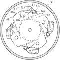
図9は、実施の形態2に係るスプール制動装置を回転軸の方向に見た断面図である。図9は、図8のA−A線断面を示す。磁石51を保持する保持部材81は、支持部81aが支持板82の孔82aに嵌合することによって、磁石51の中心とスプール12の回転軸を通る面から離隔した、スプール12の回転面に平行でかつ回転周方向に直交する軸の周りに揺動可能に支持される。磁石51は、磁石51の回転面に向き合う面とは反対の背面側で揺動可能に支持される。支持板82はスプール12が回転してもリール本体1に対して動かない。   FIG. 9 is a cross-sectional view of the spool braking device according to the second embodiment when viewed in the direction of the rotation axis. FIG. 9 shows a cross section taken along line AA of FIG. The holding member 81 for holding the magnet 51 is formed on the rotation surface of the spool 12 separated from the surface passing through the center of the magnet 51 and the rotation axis of the spool 12 by the support portion 81a fitting into the hole 82a of the support plate 82. It is supported so as to be swingable around an axis that is parallel and orthogonal to the circumferential direction of rotation. The magnet 51 is swingably supported on the back side opposite to the surface facing the rotation surface of the magnet 51. The support plate 82 does not move relative to the reel body 1 even when the spool 12 rotates.

保持部材81には、係合部81bが形成されている。係合部81bは、板バネ83の先端部にある係合孔83aに係合している。板バネ83は、保持部材81を支持部81aの周りに、磁石51のスプール12に向き合う面をスプール12の回転面から遠ざける向きに付勢する。板バネ83は、筒部80(図8参照)に支持されている。図9は、スプール12が回転していない状態を示す。釣り糸をキャストしたときに、スプール12は図9で反時計回りに回転する。   The holding member 81 has an engaging portion 81b. The engaging portion 81 b is engaged with an engaging hole 83 a at the tip of the leaf spring 83. The leaf spring 83 urges the holding member 81 around the support portion 81 a so that the surface of the magnet 51 facing the spool 12 is away from the rotation surface of the spool 12. The leaf spring 83 is supported by the cylinder portion 80 (see FIG. 8). FIG. 9 shows a state where the spool 12 is not rotating. When the fishing line is cast, the spool 12 rotates counterclockwise in FIG.

図10は、実施の形態2に係るスプール制動装置の動作を示す図である。実線で表された保持部材81および磁石51は、スプール12が回転していない状態を示す。二点鎖線で表された保持部材81および磁石51はスプールが回転している状態を示す。スプールが回転していない状態では、保持部材81は、板バネ83で付勢されて、スプール12の回転面に対向する面、特に磁石51の支持部81aの軸から遠い磁極が、スプール12の回転面から遠ざかっている。   FIG. 10 is a diagram illustrating the operation of the spool braking device according to the second embodiment. The holding member 81 and the magnet 51 represented by a solid line indicate a state where the spool 12 is not rotating. The holding member 81 and the magnet 51 represented by a two-dot chain line indicate a state where the spool is rotating. In a state where the spool is not rotating, the holding member 81 is urged by the leaf spring 83, and the surface facing the rotation surface of the spool 12, particularly the magnetic pole far from the axis of the support portion 81 a of the magnet 51, It is away from the plane of rotation.

スプール12が回転すると、スプール12の回転面に対向する磁石51の磁束によって、スプール12にはその回転速度に応じた渦電流が発生する。この渦電流によってスプール12には回転方向と逆方向の誘導力がかかる。これにより、スプール12は制動される。スプール12の回転(スプール面の移動)で磁石51によって引き起こされる誘導力の反力で、逆に磁石51はスプール12の回転する方向に引きずられる。磁石51を保持する保持部材81は、支持部81aで支持板82(図9参照)に揺動可能に支持されているので、保持部材81は支持部81aの周りに図10で反時計回りに回転する。その結果磁石51のスプール12の回転面に対向する面、特に支持部81aから遠い磁極が、スプール12の回転面に近づいていく。   When the spool 12 rotates, an eddy current corresponding to the rotation speed is generated in the spool 12 by the magnetic flux of the magnet 51 facing the rotation surface of the spool 12. Due to the eddy current, an induction force in the direction opposite to the rotation direction is applied to the spool 12. Thereby, the spool 12 is braked. On the contrary, the magnet 51 is dragged in the direction in which the spool 12 rotates due to the reaction force of the induction force caused by the rotation of the spool 12 (movement of the spool surface). Since the holding member 81 that holds the magnet 51 is swingably supported by the support plate 82 (see FIG. 9) by the support portion 81a, the holding member 81 rotates around the support portion 81a counterclockwise in FIG. Rotate. As a result, the surface of the magnet 51 that faces the rotation surface of the spool 12, in particular, the magnetic pole far from the support portion 81 a approaches the rotation surface of the spool 12.

図11は、実施の形態2に係るスプール制動装置の作用を示す概念図である。スプール12が回転していない状態では、磁石51はスプール12の回転面から遠くにあるので、スプール12の回転面に交わる磁束Bは少なく、回転面における磁界のピークは小さい。スプール12が回転して磁石51が近づくと、スプール12の回転面に交わる磁束Bが多く、回転面における磁界のピークは大きくなる。すなわち、スプール12の磁石51に向き合う面における磁束Bの、スプールの回転周方向の変化率が大きくなる。   FIG. 11 is a conceptual diagram illustrating the operation of the spool braking device according to the second embodiment. In the state where the spool 12 is not rotating, the magnet 51 is far from the rotating surface of the spool 12, so that the magnetic flux B intersecting the rotating surface of the spool 12 is small, and the magnetic field peak on the rotating surface is small. When the spool 12 rotates and the magnet 51 approaches, the magnetic flux B that intersects the rotating surface of the spool 12 increases, and the magnetic field peak on the rotating surface increases. That is, the rate of change in the circumferential direction of the spool of the magnetic flux B on the surface of the spool 12 facing the magnet 51 increases.

図12Aは、実施の形態2に係るスプール制動装置の停止状態における磁束を示す概念図である。図12Bは、実施の形態2に係るスプール制動装置の制動状態における磁束を示す概念図である。図12Aおよび図12Bの白抜き矢印は、スプール12の回転する方向を示す。図11に示されるように、スプール12が回転していない状態では磁石51はスプール12の回転面から離れ、S極の方がN極より遠くにある。そのため、スプール12が回転している場合に比べて回転面における磁界のピークは小さく、かつ、S極側の磁束がN極側の磁束より小さい。図12Aに示されるように、磁束は振幅が小さく、回転周方向を示す磁束基準線の一方に偏っている。その結果、回転周方向の磁束の変化率は小さい。スプール12が回転すると、磁石51はスプール12の回転面に近づき、S極とN極から回転面までの距離の差が小さくなる。そのため、回転面における磁界のピークが大きくなり、S極側とN極側とで磁束の差が小さくなる。図12Bに示されるように、磁束の振幅が大きくなり、回転周方向を示す磁束基準線の両側にほぼ同じ大きさで表される。その結果、回転周方向の磁束の変化率は大きくなる。誘導力は磁束の変化率に比例するので、回転周方向の磁束の変化率が大きくなれば、誘導力すなわち制動力が大きくなる。 FIG. 12A is a conceptual diagram showing a magnetic flux in a stopped state of the spool braking device according to the second embodiment. FIG. 12B is a conceptual diagram showing magnetic flux in the braking state of the spool braking device according to the second embodiment. The white arrows in FIGS. 12A and 12B indicate the direction in which the spool 12 rotates. As shown in FIG. 11, in the state in which the spool 12 is not rotating magnet 51 is rotating surface or et away are the spool 12, towards the S pole is farther from the N pole. Therefore, the magnetic field peak on the rotating surface is smaller than when the spool 12 is rotating, and the magnetic flux on the S pole side is smaller than the magnetic flux on the N pole side. As shown in FIG. 12A, the magnetic flux has a small amplitude and is biased to one of the magnetic flux reference lines indicating the rotational circumferential direction. As a result, the rate of change of magnetic flux in the rotational circumferential direction is small. When the spool 12 rotates, the magnet 51 approaches the rotating surface of the spool 12, and the difference in distance from the S pole and the N pole to the rotating surface is reduced. Therefore, the peak of the magnetic field on the rotating surface is increased, and the difference in magnetic flux between the S pole side and the N pole side is reduced. As shown in FIG. 12B, the amplitude of the magnetic flux increases, and is represented by substantially the same size on both sides of the magnetic flux reference line indicating the rotational circumferential direction. As a result, the rate of change of magnetic flux in the rotational circumferential direction increases. Since the induction force is proportional to the rate of change of the magnetic flux, if the rate of change of the magnetic flux in the rotational circumferential direction increases, the induction force, that is, the braking force increases.

実施の形態2に係るスプール制動装置20では、磁石51は、磁石51の中心とスプール12の回転軸を通る面から離隔した、スプール12の回転面に平行でかつ回転周方向に直交する軸の周りに回動可能に支持される。板バネ83は、磁石51のスプール12に向き合う面がスプール12の回転面から遠ざかる向きに磁石51を付勢する。そして、スプール12の回転で磁石51によって引き起こされる誘導力の反力で、磁石51のスプール12に向き合う面がスプール12の回転面に近づく向きに磁石51を回転させるので、スプール12の磁石51に向き合う面における磁束の、スプール12の回転周方向の変化率が大きくなる。   In the spool braking device 20 according to the second embodiment, the magnet 51 has an axis parallel to the rotation surface of the spool 12 and perpendicular to the rotation circumferential direction, which is separated from the surface passing through the center of the magnet 51 and the rotation axis of the spool 12. It is supported so as to be rotatable around. The leaf spring 83 urges the magnet 51 so that the surface of the magnet 51 facing the spool 12 moves away from the rotation surface of the spool 12. The magnet 51 is rotated in such a direction that the surface of the magnet 51 facing the spool 12 approaches the rotation surface of the spool 12 by the reaction force of the induction force caused by the magnet 51 due to the rotation of the spool 12. The rate of change of the magnetic flux in the facing surfaces in the rotational circumferential direction of the spool 12 increases.

板バネ83は、所定回転面における、スプール12の回転周方向の磁束の変化率が小さくなる方向に、磁石51を移動させる付勢部を構成する。支持板82、保持部材81および係合部81bは、スプール12の移動で磁石51によって引き起こされる誘導力の反力で、スプール12の所定回転面における、スプール12の回転周方向の磁束の変化率が大きくなる方向に、磁石51を移動させる移動機構と言える。いわば、スプール制動装置20は、スプール12の回転軸方向の所定単位幅を有する所定回転面における、磁石51が影響する回転周方向の磁束の変化率を、スプール12の回転によって変化させている。   The leaf spring 83 constitutes an urging portion that moves the magnet 51 in a direction in which the rate of change of the magnetic flux in the rotational circumferential direction of the spool 12 decreases on a predetermined rotation surface. The support plate 82, the holding member 81, and the engaging portion 81b are the reaction force of the induction force caused by the magnet 51 due to the movement of the spool 12, and the rate of change of the magnetic flux in the circumferential direction of the spool 12 on the predetermined rotation surface of the spool 12. It can be said that this is a moving mechanism that moves the magnet 51 in the direction in which the angle increases. In other words, the spool braking device 20 changes the rate of change of the magnetic flux in the circumferential direction affected by the magnet 51 on a predetermined rotation surface having a predetermined unit width in the rotation axis direction of the spool 12 by the rotation of the spool 12.

図8では、磁石51は全面がスプール12の回転面に対向しているが、実施の形態1と同様に、スプール制動装置20をスプールの回転軸方向に移動させることによって、制動力を全体的に変えることができる。実施の形態2では、支持板82をスプール12の回転軸の周りに回転させて、保持部材81の支持部81aの位置を変えることによって、スプール12が回転し始める初期の制動力を変えることができる。例えば、図9で支持板82を反時計回りに回転させると、板バネ83の係合孔83aに対して支持部81aが遠ざかるので、磁石51はスプール12の回転面からさらに遠ざかる。支持板82を時計回りに回転させれば、磁石51はスプール12の回転面に近づく。これによって、スプール12が回転しているときの最大制動力と、回転し始めるときの最小制動力との比を変化させることができる。保持部材81、支持板82および板バネ83は、磁束変化率可変機構を構成する。   In FIG. 8, the entire surface of the magnet 51 is opposed to the rotating surface of the spool 12. However, as in the first embodiment, the entire braking force is increased by moving the spool braking device 20 in the direction of the rotating shaft of the spool. Can be changed to In the second embodiment, the initial braking force at which the spool 12 starts to rotate can be changed by rotating the support plate 82 around the rotation axis of the spool 12 and changing the position of the support portion 81a of the holding member 81. it can. For example, when the support plate 82 is rotated counterclockwise in FIG. 9, the support portion 81 a moves away from the engagement hole 83 a of the leaf spring 83, so that the magnet 51 moves further away from the rotation surface of the spool 12. If the support plate 82 is rotated clockwise, the magnet 51 approaches the rotation surface of the spool 12. Thereby, the ratio of the maximum braking force when the spool 12 is rotating and the minimum braking force when the spool 12 starts to rotate can be changed. The holding member 81, the support plate 82, and the leaf spring 83 constitute a magnetic flux change rate variable mechanism.

実施の形態2のスプール制動装置20によれば、導電体(スプール12)の回転軸方向の所定単位幅を有する所定回転面における回転周方向の磁束の変化率を、導電体の回転によって変化させるので、導電体および磁石51の一方を回転軸の方向に移動させる必要がなく、スプール制動装置20の軽量化と小型化を図ることができる。   According to the spool braking device 20 of the second embodiment, the rate of change of the magnetic flux in the rotation circumferential direction on the predetermined rotation surface having the predetermined unit width in the rotation axis direction of the conductor (spool 12) is changed by the rotation of the conductor. Therefore, it is not necessary to move one of the conductor and the magnet 51 in the direction of the rotation axis, and the spool braking device 20 can be reduced in weight and size.

実施の形態2では、スプール12が導電体である場合を例に挙げて説明した。スプール12に連動する導電体があれば、スプール12は導電体でなくてもよい。例えば、非導電体で形成されたスプール12の内周面に、導電体の円筒を貼り合わせた構成でもよい。その場合、スプール制動装置20は、スプール12に連動する導電体に磁石51を対向させて配置される。   In the second embodiment, the case where the spool 12 is a conductor has been described as an example. As long as there is a conductor linked to the spool 12, the spool 12 may not be a conductor. For example, the structure which bonded the cylinder of the conductor to the inner peripheral surface of the spool 12 formed of the non-conductor may be used. In that case, the spool braking device 20 is disposed with the magnet 51 facing the conductor that is interlocked with the spool 12.

また、実施の形態2では、導電体が円筒である構成を説明した。導電体がスプール12に連動して回転するものであればスプール制動装置20を適用することができる。例えば、導電体が円板の場合でも、実施の形態2の構成を変形して適用することができる。円板は例えば、スプール12のフランジ部12aである。その場合、磁石51は、円板面に対向して配置され、磁石51の中心と円板の回転軸を通る面から離隔した位置で、円板面に平行でかつ回転周方向に直交する軸の周りに揺動可能に支持される。磁石51は、円板の磁石51に向き合う面における磁束の、円板の回転周方向の変化率が小さくなる方向に付勢される。   In the second embodiment, the configuration in which the conductor is a cylinder has been described. The spool braking device 20 can be applied as long as the conductor rotates in conjunction with the spool 12. For example, even when the conductor is a disc, the configuration of Embodiment 2 can be modified and applied. The disc is, for example, the flange portion 12 a of the spool 12. In this case, the magnet 51 is disposed opposite to the disk surface, and is an axis parallel to the disk surface and orthogonal to the rotational circumferential direction at a position separated from the surface passing through the center of the magnet 51 and the rotation axis of the disk. Is supported so as to be able to swing around. The magnet 51 is biased in a direction in which the rate of change of the magnetic flux on the surface of the disk facing the magnet 51 decreases in the rotational circumferential direction of the disk.

実施の形態2では、磁石51が4つの場合を例に取り上げた。磁石51は導電体の回転面に向き合う面にN極とS極とを有していれば、1つ以上いくつでもよい。ただし、制動力の加わる位置がスプール12の回転軸に関して対称になるように、2つ以上の磁石51を備えて回転対称の位置に配置することが好ましい。さらに、磁石51を等間隔に配置することが好ましい。なお、磁石51のN極とS極の並びは図9〜図12と逆でもよい。また、磁石51のN極とS極の並びをすべての磁石51で同じにしなくてもよい。例えば、N極とS極の並びが逆である磁石を、導電体の回転する周方向に交互に配置してもよい。   In the second embodiment, the case where there are four magnets 51 is taken as an example. One or more magnets 51 may be used as long as they have an N pole and an S pole on the surface facing the rotating surface of the conductor. However, it is preferable to provide two or more magnets 51 and arrange them at rotationally symmetric positions so that the position where the braking force is applied is symmetric with respect to the rotation axis of the spool 12. Furthermore, it is preferable to arrange the magnets 51 at equal intervals. The arrangement of the N pole and the S pole of the magnet 51 may be the reverse of that shown in FIGS. Further, the N poles and the S poles of the magnets 51 may not be the same for all the magnets 51. For example, magnets in which the arrangement of the N pole and the S pole are reversed may be alternately arranged in the circumferential direction in which the conductor rotates.

1 リール本体
2 ハンドル
12 スプール
12a フランジ部
12b 糸巻胴部
16 スプール軸
20 スプール制動装置
60 筒部
60a 案内孔(実施の形態1)
61 保持部材(実施の形態1)
61a 支持部
61b 係合部
62 支持リング
62a 孔
63 係合部材
63a 係合孔
64 ピン
65 操作つまみ
65a つまみ部
65b 押圧部
70 筒部(変形例)
70a 案内孔(変形例)
70b 平歯(変形例)
71 保持部材(変形例)
71a 外歯(変形例)
80 筒部
81 保持部材(実施の形態2)
81a 支持部
81b 係合部
82 支持板
82a 孔
83 板バネ
83a 係合孔
DESCRIPTION OF SYMBOLS 1 Reel body 2 Handle 12 Spool 12a Flange part 12b Bobbin trunk 16 Spool shaft 20 Spool brake device 60 Cylinder part 60a Guide hole (Embodiment 1)
61 Holding member (Embodiment 1)
61a support part 61b engagement part 62 support ring 62a hole 63 engagement member 63a engagement hole 64 pin 65 operation knob 65a knob part 65b pressing part 70 cylinder part (modified example)
70a Guide hole (modified example)
70b flat teeth (modified)
71 Holding Member (Modification)
71a external teeth (modified example)
80 cylinder part 81 holding member (Embodiment 2)
81a Support portion 81b Engagement portion 82 Support plate 82a Hole 83 Leaf spring 83a Engagement hole

Claims (9)

リール本体に回転可能に支持されるスプールの回転を制動するスプール制動装置であって、
前記スプールに連動して回転する導電体と、
前記導電体の回転面に向き合う面にN極とS極とを有する磁石と、
前記導電体の回転によって、前記導電体に対して前記磁石の磁気双極子の向きを変化させて、前記導電体の回転周方向に直交する方向の所定単位幅を有する所定回転面における、前記磁石が影響する回転周方向の磁束の変化率を変化させる磁束変化率可変機構と、
を備えるスプール制動装置。
A spool braking device that brakes rotation of a spool rotatably supported by a reel body,
A conductor that rotates in conjunction with the spool;
A magnet having an N pole and an S pole on a surface facing the rotating surface of the conductor;
The magnet on a predetermined rotation surface having a predetermined unit width in a direction orthogonal to a rotation circumferential direction of the conductor by changing a direction of a magnetic dipole of the magnet with respect to the conductor by rotation of the conductor. and the magnetic flux variation rate varying mechanism but to change the rate of change of the rotational circumferential direction of the magnetic flux that affects,
A spool braking device comprising:
前記磁束変化率可変機構は、
前記導電体の移動で前記磁石によって引き起こされる誘導力の反力で、前記所定回転面における、前記導電体の回転周方向の磁束の変化率が大きくなる方向に、前記磁石を移動させる移動機構を
備える請求項1記載のスプール制動装置。
The magnetic flux change rate variable mechanism is:
A moving mechanism for moving the magnet in a direction in which the rate of change of the magnetic flux in the rotational circumferential direction of the conductor increases on the predetermined rotation surface by a reaction force of an induction force caused by the magnet by the movement of the conductor; The spool braking device according to claim 1 provided.
前記磁束変化率可変機構は、
前記所定回転面における、前記導電体の回転周方向の磁束の変化率が小さくなる方向に、前記磁石を移動させる付勢部を
備える請求項2記載のスプール制動装置。
The magnetic flux change rate variable mechanism is:
The spool braking device according to claim 2, further comprising: an urging portion that moves the magnet in a direction in which a rate of change in magnetic flux in a rotation circumferential direction of the conductor is reduced on the predetermined rotation surface.
前記磁石は、
前記導電体の前記磁石に向き合う面に直交する軸の周りに回動可能に支持され、
前記磁束変化率可変機構は、
前記回転面の回転周方向に直交する方向における所定単位幅において、前記N極と前記S極とが前記導電体の回転周方向に並ぶ向きに前記磁石を回転させる回転機構を備える、
請求項1から3のいずれか1項に記載のスプール制動装置。
The magnet
Supported around a shaft orthogonal to the surface of the conductor facing the magnet;
The magnetic flux change rate variable mechanism is:
A rotation mechanism for rotating the magnet in a direction in which the N pole and the S pole are aligned in the rotation circumferential direction of the conductor in a predetermined unit width in a direction orthogonal to the rotation circumferential direction of the rotation surface;
The spool braking device according to any one of claims 1 to 3.
前記回転機構は、
前記導電体の回転軸の周りに回転可能に支持される回転部材と、
前記磁石を保持し、前記磁石の前記導電体に向き合う面の向きを維持しながら前記N極と前記S極との中間の周りに回動可能に、前記回転部材に支持されるカムと、
前記カムに係合し、前記導電体が回転する周方向の前記磁石の動きを、前記カムの回動に変換する係合部材と、
を備える請求項4記載のスプール制動装置。
The rotation mechanism is
A rotating member that is rotatably supported around a rotation axis of the conductor;
A cam that is supported by the rotating member so as to be rotatable about the middle of the N pole and the S pole while holding the magnet and maintaining the orientation of the surface of the magnet facing the conductor;
An engaging member that engages with the cam and converts the movement of the magnet in the circumferential direction in which the conductor rotates to rotation of the cam;
A spool braking device according to claim 4.
前記回転機構は、
前記導電体の回転軸の周りに回転可能に支持される回転部材と、
前記磁石を保持し、前記磁石の前記導電体に向き合う面に向かって周りに外歯を有し、前記磁石の前記導電体に向き合う面の向きを維持しながら前記N極と前記S極との中間の周りに回動可能に、前記回転部材に支持されるピニオンと、
前記ピニオンの前記外歯に噛合する、前記導電体の回転周方向に一列に形成された平歯を有し、前記リール本体に固定されたラックと、
を備える請求項4記載のスプール制動装置。
The rotation mechanism is
A rotating member that is rotatably supported around a rotation axis of the conductor;
Holding the magnet, having external teeth around the surface of the magnet facing the conductor, and maintaining the orientation of the surface of the magnet facing the conductor between the N pole and the S pole A pinion supported by the rotating member so as to be rotatable around the middle;
A rack that meshes with the external teeth of the pinion and has flat teeth formed in a row in the rotational circumferential direction of the conductor, and is fixed to the reel body;
A spool braking device according to claim 4.
前記磁石は、
前記導電体の前記磁石に向き合う面と並行する軸の周りに揺動可能に支持され、
前記磁束変化率可変機構は、
前記回転面の回転周方向に直交する方向おける所定単位幅において、前記N極と前記S極の双方が前記導電体の回転周方向に近接する向きに前記磁石を揺動させる揺動機構を備える、
請求項1から3のいずれか1項に記載のスプール制動装置。
The magnet
Supported around a shaft parallel to the surface of the conductor facing the magnet, and swingable.
The magnetic flux change rate variable mechanism is:
In predetermined unit width definitive in the direction perpendicular to the circumferential direction of rotation of the rotating surface, the swinging mechanism for swinging the magnet in a direction in which both the S pole and the N pole is close to the circumferential direction of rotation of the conductor Prepare
The spool braking device according to any one of claims 1 to 3.
2以上の前記磁石を備え、
前記磁石はそれぞれ、前記導電体の回転軸を対称軸として回転対称の位置に配置される、
請求項1から7のいずれか1項に記載のスプール制動装置。
Comprising two or more magnets;
Each of the magnets is disposed at a rotationally symmetric position with respect to the rotational axis of the conductor.
The spool braking device according to any one of claims 1 to 7.
釣り竿に取り付けられるリール本体と、
前記リール本体に回転可能に支持され、釣り糸を外周に巻き取るスプールと、
請求項1から8のいずれか1項に記載のスプール制動装置と、
を備える魚釣用リール。
A reel body attached to a fishing rod;
A spool that is rotatably supported by the reel body and winds a fishing line around the outer circumference;
The spool braking device according to any one of claims 1 to 8,
Fishing reel equipped with.
JP2014162611A 2014-08-08 2014-08-08 Spool braking device and fishing reel Active JP6351433B2 (en)

Priority Applications (5)

Application Number Priority Date Filing Date Title
JP2014162611A JP6351433B2 (en) 2014-08-08 2014-08-08 Spool braking device and fishing reel
KR1020150064612A KR102392206B1 (en) 2014-08-08 2015-05-08 Brake mechanism for spool and fishing reel
TW104118958A TWI656838B (en) 2014-08-08 2015-06-11 Roll brake device and fishing reel
US14/813,685 US9955678B2 (en) 2014-08-08 2015-07-30 Spool braking device and fishing reel
CN201510477855.8A CN105360080B (en) 2014-08-08 2015-08-06 Spool brake device and fishing reel

Applications Claiming Priority (1)

Application Number Priority Date Filing Date Title
JP2014162611A JP6351433B2 (en) 2014-08-08 2014-08-08 Spool braking device and fishing reel

Publications (3)

Publication Number Publication Date
JP2016036308A JP2016036308A (en) 2016-03-22
JP2016036308A5 JP2016036308A5 (en) 2017-08-10
JP6351433B2 true JP6351433B2 (en) 2018-07-04

Family

ID=55266400

Family Applications (1)

Application Number Title Priority Date Filing Date
JP2014162611A Active JP6351433B2 (en) 2014-08-08 2014-08-08 Spool braking device and fishing reel

Country Status (5)

Country Link
US (1) US9955678B2 (en)
JP (1) JP6351433B2 (en)
KR (1) KR102392206B1 (en)
CN (1) CN105360080B (en)
TW (1) TWI656838B (en)

Families Citing this family (17)

* Cited by examiner, † Cited by third party
Publication number Priority date Publication date Assignee Title
JP6543041B2 (en) * 2015-02-12 2019-07-10 株式会社シマノ Spool brake and fishing reel
JP6688679B2 (en) * 2016-05-24 2020-04-28 株式会社シマノ Double bearing reel
KR101790778B1 (en) * 2016-06-08 2017-10-26 유한책임회사 도요엔지니어링 Bait casting reel
US10602730B2 (en) * 2017-06-23 2020-03-31 Shimano Inc. Dual-bearing reel
JP6979844B2 (en) * 2017-10-06 2021-12-15 株式会社シマノ Rotation transmission mechanism and spinning reel for fishing equipped with it
JP7032225B2 (en) * 2018-04-26 2022-03-08 シマノコンポネンツ マレーシア エスディーエヌ.ビーエッチディー. Torque limiting device for fishing reels and spinning reels
KR102095305B1 (en) * 2018-05-31 2020-04-01 유한책임회사 도요엔지니어링 Bait casting reel
JP7046743B2 (en) * 2018-07-06 2022-04-04 株式会社シマノ Spinning reel
JP7164450B2 (en) 2019-01-29 2022-11-01 グローブライド株式会社 Double bearing type reel
KR102233310B1 (en) * 2019-01-30 2021-03-29 유한책임회사 도요엔지니어링 Fishing reel with movable magnet brake
KR102280541B1 (en) * 2019-03-28 2021-07-26 유한책임회사 도요엔지니어링 Fishing reel
KR102292063B1 (en) * 2019-10-07 2021-08-20 유한책임회사 도요엔지니어링 Fishing reel
CN111328777A (en) * 2020-04-24 2020-06-26 深圳波赛冬网络科技有限公司 Double-brake structure, water droplet wheel and fishing tackle
JP2022022175A (en) * 2020-07-23 2022-02-03 ピュア・フィッシング・インコーポレーテッド Magnetic casting brake
JP2023028978A (en) * 2021-08-20 2023-03-03 グローブライド株式会社 Brake force controller and fishing reel comprising the same
KR20230061807A (en) 2021-10-29 2023-05-09 유한책임회사 도요엔지니어링 Fishing reel
CN114451371B (en) * 2021-11-05 2023-01-24 宁波市西赛德渔具有限公司 Fishing reel with magnetic slow-descending structure

Family Cites Families (21)

* Cited by examiner, † Cited by third party
Publication number Priority date Publication date Assignee Title
JPS5880869U (en) * 1981-11-26 1983-06-01 株式会社シマノ double shaft reel
US4561605A (en) * 1981-12-25 1985-12-31 Shimano Industrial Company Limited Brake for a fishing reel
US4544111A (en) * 1982-03-09 1985-10-01 Shimano Industrial Company Limited Brake for a fishing reel
JPS58165727A (en) * 1982-03-26 1983-09-30 株式会社シマノ Dual bearing reel
JPS59154055U (en) * 1983-03-30 1984-10-16 株式会社シマノ double bearing reel
JPS59166666U (en) * 1983-04-20 1984-11-08 株式会社シマノ fishing reel
JPS59170469U (en) * 1983-04-27 1984-11-14 株式会社シマノ double bearing reel
JPS6120165U (en) * 1984-07-11 1986-02-05 株式会社シマノ fishing reel
JPS6163228A (en) * 1984-09-03 1986-04-01 ダイワ精工株式会社 Backrash preventing apparatus of fishing reel
DE4125895C2 (en) * 1990-08-07 2002-08-08 Shimano Kk Bait casting reel
JPH0713164U (en) * 1993-08-04 1995-03-07 ダイワ精工株式会社 Double bearing reel with backlash prevention device
JPH0717064U (en) * 1993-09-14 1995-03-28 ダイワ精工株式会社 Backlash prevention device for dual-bearing reels for fishing
JP2929517B2 (en) * 1994-04-01 1999-08-03 ダイワ精工株式会社 Backlash prevention device for fishing reels
JP3325773B2 (en) * 1996-05-16 2002-09-17 株式会社シマノ Dual bearing reel braking system
JP3515875B2 (en) 1997-03-21 2004-04-05 ダイワ精工株式会社 Fishing reel
JPH11299403A (en) * 1998-04-24 1999-11-02 Ryobi Ltd Backlash preventing device in double bearing reel
JP3576385B2 (en) * 1998-06-04 2004-10-13 ダイワ精工株式会社 Double bearing reel for fishing
JP3955725B2 (en) * 2000-11-10 2007-08-08 ダイワ精工株式会社 Double bearing reel for fishing
JP2008245552A (en) * 2007-03-29 2008-10-16 Daiwa Seiko Inc Spinning reel
JP2011206013A (en) * 2010-03-30 2011-10-20 Globeride Inc Spinning reel
JP5944742B2 (en) * 2012-05-17 2016-07-05 株式会社シマノ Spool brake device for double-bearing reel and double-bearing reel

Also Published As

Publication number Publication date
US20160037759A1 (en) 2016-02-11
CN105360080B (en) 2020-12-22
TW201605341A (en) 2016-02-16
KR102392206B1 (en) 2022-04-29
JP2016036308A (en) 2016-03-22
CN105360080A (en) 2016-03-02
TWI656838B (en) 2019-04-21
KR20160018336A (en) 2016-02-17
US9955678B2 (en) 2018-05-01

Similar Documents

Publication Publication Date Title
JP6351433B2 (en) Spool braking device and fishing reel
JP6543041B2 (en) Spool brake and fishing reel
JP5944742B2 (en) Spool brake device for double-bearing reel and double-bearing reel
JP3325773B2 (en) Dual bearing reel braking system
JP6829020B2 (en) Double bearing reel
JP6240398B2 (en) Spool brake device for double-bearing reel and double-bearing reel
CN110710499B (en) Dual-bearing reel
JP6739593B2 (en) Fishing reel
JP6739594B2 (en) Fishing reel
JP6829018B2 (en) Double bearing reel
JP6200189B2 (en) Spool brake device for double-bearing reel and double-bearing reel
JP2014233260A (en) Spool brake device of double-bearing reel
JP2001017044A (en) Brake for reel supported with bearings at both ends
JPH10155402A (en) Spool for double bearing reel
JP2002125544A (en) Spool braking device of double bearing reel
JPH11299403A (en) Backlash preventing device in double bearing reel

Legal Events

Date Code Title Description
A521 Request for written amendment filed

Free format text: JAPANESE INTERMEDIATE CODE: A523

Effective date: 20170628

A621 Written request for application examination

Free format text: JAPANESE INTERMEDIATE CODE: A621

Effective date: 20170628

A131 Notification of reasons for refusal

Free format text: JAPANESE INTERMEDIATE CODE: A131

Effective date: 20180123

A977 Report on retrieval

Free format text: JAPANESE INTERMEDIATE CODE: A971007

Effective date: 20180124

A521 Request for written amendment filed

Free format text: JAPANESE INTERMEDIATE CODE: A523

Effective date: 20180306

TRDD Decision of grant or rejection written
A01 Written decision to grant a patent or to grant a registration (utility model)

Free format text: JAPANESE INTERMEDIATE CODE: A01

Effective date: 20180529

A61 First payment of annual fees (during grant procedure)

Free format text: JAPANESE INTERMEDIATE CODE: A61

Effective date: 20180605

R150 Certificate of patent or registration of utility model

Ref document number: 6351433

Country of ref document: JP

Free format text: JAPANESE INTERMEDIATE CODE: R150

R250 Receipt of annual fees

Free format text: JAPANESE INTERMEDIATE CODE: R250

R250 Receipt of annual fees

Free format text: JAPANESE INTERMEDIATE CODE: R250

R250 Receipt of annual fees

Free format text: JAPANESE INTERMEDIATE CODE: R250