JP6351246B2 - Image shake correction apparatus, control method therefor, optical apparatus, and imaging apparatus - Google Patents
Image shake correction apparatus, control method therefor, optical apparatus, and imaging apparatus Download PDFInfo
- Publication number
- JP6351246B2 JP6351246B2 JP2013257050A JP2013257050A JP6351246B2 JP 6351246 B2 JP6351246 B2 JP 6351246B2 JP 2013257050 A JP2013257050 A JP 2013257050A JP 2013257050 A JP2013257050 A JP 2013257050A JP 6351246 B2 JP6351246 B2 JP 6351246B2
- Authority
- JP
- Japan
- Prior art keywords
- shake
- panning
- frequency
- low
- signal
- Prior art date
- Legal status (The legal status is an assumption and is not a legal conclusion. Google has not performed a legal analysis and makes no representation as to the accuracy of the status listed.)
- Active
Links
Images


Classifications
-
- G—PHYSICS
- G02—OPTICS
- G02B—OPTICAL ELEMENTS, SYSTEMS OR APPARATUS
- G02B7/00—Mountings, adjusting means, or light-tight connections, for optical elements
- G02B7/02—Mountings, adjusting means, or light-tight connections, for optical elements for lenses
- G02B7/023—Mountings, adjusting means, or light-tight connections, for optical elements for lenses permitting adjustment
-
- G—PHYSICS
- G02—OPTICS
- G02B—OPTICAL ELEMENTS, SYSTEMS OR APPARATUS
- G02B27/00—Optical systems or apparatus not provided for by any of the groups G02B1/00 - G02B26/00, G02B30/00
- G02B27/64—Imaging systems using optical elements for stabilisation of the lateral and angular position of the image
- G02B27/646—Imaging systems using optical elements for stabilisation of the lateral and angular position of the image compensating for small deviations, e.g. due to vibration or shake
-
- H—ELECTRICITY
- H04—ELECTRIC COMMUNICATION TECHNIQUE
- H04N—PICTORIAL COMMUNICATION, e.g. TELEVISION
- H04N23/00—Cameras or camera modules comprising electronic image sensors; Control thereof
- H04N23/60—Control of cameras or camera modules
- H04N23/68—Control of cameras or camera modules for stable pick-up of the scene, e.g. compensating for camera body vibrations
- H04N23/681—Motion detection
- H04N23/6812—Motion detection based on additional sensors, e.g. acceleration sensors
-
- H—ELECTRICITY
- H04—ELECTRIC COMMUNICATION TECHNIQUE
- H04N—PICTORIAL COMMUNICATION, e.g. TELEVISION
- H04N23/00—Cameras or camera modules comprising electronic image sensors; Control thereof
- H04N23/60—Control of cameras or camera modules
- H04N23/68—Control of cameras or camera modules for stable pick-up of the scene, e.g. compensating for camera body vibrations
- H04N23/681—Motion detection
- H04N23/6815—Motion detection by distinguishing pan or tilt from motion
-
- H—ELECTRICITY
- H04—ELECTRIC COMMUNICATION TECHNIQUE
- H04N—PICTORIAL COMMUNICATION, e.g. TELEVISION
- H04N23/00—Cameras or camera modules comprising electronic image sensors; Control thereof
- H04N23/60—Control of cameras or camera modules
- H04N23/68—Control of cameras or camera modules for stable pick-up of the scene, e.g. compensating for camera body vibrations
- H04N23/682—Vibration or motion blur correction
- H04N23/685—Vibration or motion blur correction performed by mechanical compensation
- H04N23/687—Vibration or motion blur correction performed by mechanical compensation by shifting the lens or sensor position
Description
本発明は、光学機器や撮像装置等における像振れ補正技術に関する。 The present invention relates to an image blur correction technique in an optical apparatus, an imaging apparatus, or the like.
デジタルカメラ等の撮像装置で撮像された画像には、例えば撮像時にカメラ本体部を保持するユーザの手振れ等より像振れを生じる場合がある。このため、カメラ本体部に加えられた振動を検出して、被写体の像振れを補正する機能をもつ装置がある。光学式像振れ補正処理や電子式像振れ補正処理が知られている。光学式像振れ補正処理では、角速度センサ等でカメラ本体部の振れを検出し、撮影光学系内の光学部材(補正レンズ)を移動させて撮影光学系の光軸方向を変化させる。これにより撮像素子の受光面に結像される像を移動して振れを補正できる。また、電子式像振れ補正処理では、撮像画像に画像処理を施して擬似的に像振れが補正される。 An image captured by an imaging device such as a digital camera may cause image blur due to, for example, camera shake of a user holding the camera body during imaging. For this reason, there is a device having a function of correcting vibration of a subject by detecting vibration applied to the camera body. Optical image blur correction processing and electronic image blur correction processing are known. In the optical image shake correction process, the shake of the camera body is detected by an angular velocity sensor or the like, and the optical member (correction lens) in the shooting optical system is moved to change the optical axis direction of the shooting optical system. Thereby, the image formed on the light receiving surface of the image sensor can be moved to correct the shake. In the electronic image blur correction process, image processing is performed on the captured image to artificially correct the image blur.
角速度センサ等から出力される振れ検出信号は、手振れ等の補正すべき振動に起因する信号の他に、パンニング操作のような撮影者の意図的なカメラ操作に起因する信号等も含む。よって、単に振れ検出信号に基づいて補正レンズを駆動すると、パンニングやチルティングの操作(以下、パン操作等という)時のような大きな振れに対しても像振れ補正が行われる。そのため、補正レンズの目標位置が可動範囲を超えてしまう可能性がある。あるいは、パン操作等の後に画像揺れ(揺れ戻し)が生じ、ユーザがカメラ操作や映像に違和感を抱く可能性がある。揺れ戻し補正処理では、角速度センサの振れ検出信号がパン操作等によるものであると判断した場合、像振れ補正を停止する。補正レンズは可動範囲の中心(変位量0とする基準位置)に戻して停止される。 The shake detection signal output from the angular velocity sensor or the like includes a signal caused by an intentional camera operation of the photographer such as a panning operation, in addition to a signal caused by vibration to be corrected such as camera shake. Therefore, when the correction lens is driven simply based on the shake detection signal, image shake correction is performed even for large shakes during panning or tilting operations (hereinafter referred to as panning operations or the like). Therefore, the target position of the correction lens may exceed the movable range. Alternatively, image shaking (back shaking) may occur after panning or the like, and the user may feel uncomfortable with camera operation or video. In the shake back correction process, when it is determined that the shake detection signal of the angular velocity sensor is due to a pan operation or the like, the image shake correction is stopped. The correction lens is returned to the center of the movable range (a reference position where the displacement amount is 0) and stopped.
ところで、パン操作等の終了時に角速度の急激な変化が生じた際、検出信号処理系のハイパスフィルタ(HPF)や積分器の残留信号等により振れ検出信号が厳密には0にならず、漸進的に0に近づくことがある。このため、像振れ補正の再開の際に補正レンズが振れ検出信号により大きく動き、画像の揺れ戻しが発生する。その対策として、特許文献1に開示の装置は、角速度の信号処理系フィルタのカットオフ周波数をパン操作等の終了時に段階的に変化させる像振れ補正を行う。また、特許文献2では、揺れ戻しの原因となっている角速度の信号処理系フィルタに極低域のカットオフ周波数を持つHPFやLPF(積分器)を使用せずに、補正レンズの駆動を角速度に応じた速度制御で行う方法を開示する。また、特許文献3に開示の装置は、角速度センサで検出した振れ信号に基づき補正レンズにより振れを補正し、低周波成分の振れ信号に基づき電子式像振れ補正により振れを補正する。これにより、パン操作等での大きな振れに対して補正レンズの駆動域を十分に確保できる。
By the way, when an abrupt change in angular velocity occurs at the end of the pan operation or the like, the shake detection signal does not become strictly zero due to the high-pass filter (HPF) of the detection signal processing system or the residual signal of the integrator, but gradually. May approach 0. For this reason, when the image blur correction is restarted, the correction lens moves greatly due to the shake detection signal, and the image is shaken back. As a countermeasure, the apparatus disclosed in
特許文献1に記載の技術では、パン操作等の直後の像振れ補正効果が弱くなってしまうという課題がある。また、特許文献2に記載の技術では、露光時以外では補正レンズを位置制御によりセンタリングする動作となるため、ユーザの体の揺れ等の、振れ検出信号の低域成分に対する像振れ補正効果が弱くなる。また、HPFを用いないため、角速度センサのオフセットや温度変動が大きい場合に、補正レンズの位置が可動範囲の中心から乖離してしまうという課題もある。オフセットや温度変動の少ない水晶ジャイロセンサ等を使用すると、コスト上昇を招く原因となる。また、特許文献3に記載の技術では、電子式像振れ補正を行うことができない場合、露光時の低周波数の像振れ補正性能が低下するという課題がある。
本発明は、パン操作等の際に大きな振れが生じた場合でも良好な像振れ補正を実現する像振れ補正装置の提供を目的とする。
The technique described in
SUMMARY OF THE INVENTION An object of the present invention is to provide an image shake correction apparatus that realizes good image shake correction even when a large shake occurs during a pan operation or the like.
本発明の像振れ補正装置は、振れ検出信号を複数の周波数成分に分割する分割手段と、前記振れ検出信号からパンニングまたはチルティングが判定された場合、パンニングまたはチルティングの速度を検出し、検出した前記速度に基づいて、前記分割された複数の周波数成分に対するそれぞれのフィルタ演算のカットオフ周波数または当該フィルタ演算にて算出される中間値を独立に変更し、前記フィルタ演算を行った信号を合成して振れ補正手段の制御信号を生成する制御手段と、を備え、前記制御手段は、パンニングまたはチルティングの速度が閾値以下である場合、前記振れ補正手段に係る低周波の目標位置を収束させ、前記振れ補正手段に係る高周波の目標位置を収束させる制御を行わず、パンニングまたはチルティングの速度が前記閾値より大きい場合、前記振れ補正手段に係る低周波及び高周波の目標位置をともに収束させる。 An image shake correction apparatus according to the present invention includes a dividing unit that divides a shake detection signal into a plurality of frequency components, and detects panning or tilting speed when panning or tilting is determined from the shake detection signal. Based on the speed, the cut-off frequency of each filter operation for the divided frequency components or the intermediate value calculated by the filter operation is independently changed, and the signal subjected to the filter operation is synthesized. And a control means for generating a control signal for the shake correction means, and the control means converges a low frequency target position related to the shake correction means when the speed of panning or tilting is equal to or less than a threshold value. The control of converging the high frequency target position related to the shake correction means is not performed, and the panning or tilting speed is Larger than the threshold, Ru together converges the target position of the low and high frequency according to the shake correction means.
本発明の像振れ補正装置によれば、パン操作等の際に大きな振れが生じた場合でも良好な像振れ補正を実現することができる。 According to the image blur correction apparatus of the present invention, it is possible to realize good image blur correction even when a large blur occurs during a pan operation or the like.
以下、本発明の好適な実施形態について添付図面を参照して詳細に説明する。本発明は、デジタル一眼レフカメラに装着される交換レンズやレンズ鏡筒のような光学機器、デジタルビデオカメラ、監視カメラ、Webカメラ等の撮影装置、携帯電話やタブレット端末等の撮影装置を具備する電子機器に適用できる。尚、本発明は以下の実施形態に限定されるものではなく、本発明の実施に有利な具体例を示すにすぎない。また、以下の実施形態の中で説明されている特徴の組み合わせの全てが本発明の課題解決のために必須のものであるとは限らない。 DESCRIPTION OF EMBODIMENTS Hereinafter, preferred embodiments of the present invention will be described in detail with reference to the accompanying drawings. The present invention includes an optical device such as an interchangeable lens and a lens barrel attached to a digital single lens reflex camera, a photographing device such as a digital video camera, a surveillance camera, and a Web camera, and a photographing device such as a mobile phone and a tablet terminal. Applicable to electronic equipment. In addition, this invention is not limited to the following embodiment, It shows only the specific example advantageous for implementation of this invention. Moreover, not all combinations of features described in the following embodiments are indispensable for solving the problems of the present invention.
図1は、本発明の実施形態に係る撮像装置の機能構成例を示すブロック図である。本実施形態に係る撮像装置として、デジタルスチルカメラを例示するが、動画撮影機能を有するカメラでもよい。 FIG. 1 is a block diagram illustrating a functional configuration example of an imaging apparatus according to an embodiment of the present invention. Although a digital still camera is illustrated as an imaging apparatus according to the present embodiment, a camera having a moving image shooting function may be used.
撮影光学系(結像光学系)を構成するズームユニット101は、倍率が可変な撮影レンズ装置の一部であり、撮影レンズ装置の倍率を変更するズームレンズを含む。ズーム駆動制御部102は、システム制御部119の制御指令に従ってズームユニット101の駆動を制御する。振れ補正レンズ(以下、補正レンズという)103は、像振れ補正部材として撮影光学系の一部を構成する光学部材である。補正レンズ103は、撮影光学系の光軸と異なる方向、例えば光軸と直交する方向に移動可能なシフトレンズである。振れ補正レンズ駆動制御部104は、システム制御部119の制御指令に従って補正レンズ103を駆動する。
The
絞り・シャッタユニット105は、絞り機能を有するメカニカルシャッタを有する。絞り・シャッタ駆動制御部106は、システム制御部119の制御指令に従って絞り・シャッタユニット105を駆動する。フォーカスユニット107は撮影レンズの一部であり、撮影レンズの光軸に沿って位置を変更可能なフォーカスレンズを有する。フォーカス駆動制御部108は、システム制御部119の制御指令に従ってフォーカスユニット107を駆動し、焦点調節動作を行う。
The aperture /
撮像部109は、CCD(電荷結合素子)イメージセンサやCMOS(相補型金属酸化膜半導体)イメージセンサ等の撮像素子を備える。撮像素子は、撮影光学系により結像される光学像を、画素単位の電気信号に光電変換する。撮像信号処理部110は、撮像部109が出力した電気信号に対して、A(アナログ)/D(デジタル)変換、相関二重サンプリング、ガンマ補正、ホワイトバランス補正、色補間処理等を行い、映像信号に変換する。映像信号処理部111は、撮像信号処理部110から出力された映像信号を、用途に応じて加工する。具体的には、映像信号処理部111は表示用の映像信号を生成し、記録用に符号化処理やデータのファイル化処理を行う。
The
表示部112は、映像信号処理部111が出力する表示用の映像信号に基づいて、必要に応じて画像表示を行う。電源部115は、撮像装置全体に、用途に応じて電源を供給する。外部入出力端子部116は、外部装置との間で通信信号及び映像信号の入出力に使用する。操作部117はユーザが撮像装置を操作する際に使用し、撮像装置に指示を与えるためのボタンやスイッチ等を有する。記憶部118は、映像情報等の様々なデータを記憶する。カメラシステムを制御するシステム制御部119はCPU(中央演算処理装置)、ROM(リード・オンリ・メモリ)、RAM(ランダム・アクセス・メモリ)等を有する。ROMに記憶された制御プログラムをRAMに展開してCPUが実行することによって、撮像装置の各部が制御され、以下に説明する様々な動作が実現される。
The
操作部117は、レリーズボタンの押し込み量に応じて第1スイッチ(SW1と記す)及び第2スイッチ(SW2と記す)が順にオンするように構成されたレリーズスイッチを含む。レリーズボタンが約半分押し込まれたときにSW1がオンし、レリーズボタンが最後まで押し込まれたときにSW2がオンする。SW1がオンすると、システム制御部119は、AF(オートフォーカス)評価値に基づいてフォーカス駆動制御部108を制御することにより焦点調節を行う。AF評価値は、例えば映像信号処理部111が表示部112に出力する表示用の映像信号に基づいて生成される。
The
システム制御部119は映像信号の輝度情報を取得し、AE(自動露出)処理を行う。例えば予め定められたプログラム線図に基づいて適切な露光量を得るための絞り値及びシャッタ速度が決定される。SW2がオンすると、システム制御部119は決定した絞り及びシャッタ速度での撮影動作を行い、撮像部109によって得られた画像データを記憶部118に記憶させる制御等を行う。
The
操作部117は、像振れ補正モードを選択するための像振れ補正スイッチを含む。像振れ補正スイッチの操作により像振れ補正モードが選択された場合、システム制御部119は振れ補正レンズ駆動制御部104に対して振れ補正動作を指示する。この指示を受けた振れ補正レンズ駆動制御部104は像振れ補正のオフ指示がなされるまで振れ補正動作を続行する。また、操作部117は、静止画撮影モードや動画撮影モード等を選択するためのモード選択スイッチを含む。選択された各撮影モードにおいて振れ補正レンズ駆動制御部104の動作条件を変更することができる。また、操作部117には再生モードを選択するための再生モード選択スイッチも含まれており、再生モード時には振れ補正動作を停止する。操作部117は、ズーム倍率変更の指示を行うための倍率変更スイッチを含む。倍率変更スイッチの操作によりズーム倍率変更の指示があった場合、システム制御部119はズーム駆動制御部102に指示を出してズームユニット101を駆動する。ズームレンズは指示された位置に移動して変倍動作が行われる。
The
次に、図2(A)を参照して、振れ補正レンズ駆動制御部104の構成を説明する。図2(A)は、振れ補正レンズ駆動制御部104の機能構成例を示すブロック図である。振れ検出部は、複数の方向におけるそれぞれの振れを検出するために、第1振れセンサ201及び第2振れセンサ202を備える。
Next, the configuration of the shake correction lens
第1振れセンサ201は、例えば角速度センサであり、通常の姿勢(画像の長手方向が水平方向とほぼ一致する基準姿勢)における、撮像装置の垂直方向(ピッチ方向)の振れを検出する。第1振れセンサ201は、振れ検出信号を第1振れ補正制御部203に出力する。第2振れセンサ202は、例えば角速度センサであり、通常の姿勢における撮像装置の水平方向(ヨー方向)の振れを検出する。第2振れセンサ202は、振れ検出信号を第2振れ補正制御部204に出力する。
The
第1及び第2振れ補正制御部203,204はそれぞれ、ピッチ方向、ヨー方向における補正レンズ103の目標位置を決定し、目標位置に関する補正位置制御信号を出力し、補正レンズ103の駆動を制御する。第1振れ補正制御部203は補正位置制御信号を第1レンズ位置制御部205に出力し、第2振れ補正制御部204は補正位置制御信号を第2レンズ位置制御部206に出力する。
The first and second shake
第1レンズ位置制御部205は、フィードバック制御によって、例えばアクチュエータを含む第1ドライブ部207の駆動制御を行う。このフィードバック制御は、第1振れ補正制御部203からのピッチ方向における補正位置制御信号と、後述する位置検出信号に基づいて実行される。同様に、第2レンズ位置制御部206は、フィードバック制御によって、アクチュエータを含む第2ドライブ部208の駆動制御を行う。このフィードバック制御は、第2振れ補正制御部204からのヨー方向における補正位置制御信号と、後述する位置検出信号に基づいて実行される。
The first lens
補正レンズ103の位置検出部は、2つの方向に対応する位置情報を取得するために、第1ホール素子209及び第2ホール素子210を備える。第1ホール素子209は、補正レンズ103のピッチ方向における位置検出を行い、検出した位置情報を第1レンズ位置制御部205に出力する。また、第2ホール素子210は、補正レンズ103のヨー方向における位置検出を行い、検出した位置情報を第2レンズ位置制御部206に出力する。
The position detection unit of the
次に、振れ補正レンズ駆動制御部104が行う補正レンズ103の駆動制御について説明する。第1及び第2振れ補正制御部203,204はそれぞれ、第1及び第2振れセンサ201,202から、撮像装置のピッチ方向、ヨー方向の振れを表す振れ検出信号(角速度信号)を取得する。第1及び第2振れ補正制御部203,204は、振れ検出信号に基づいて、ピッチ方向及びヨー方向に補正レンズ103を駆動する補正位置制御信号を生成し、第1及び第2レンズ位置制御部205,206にそれぞれ出力する。
Next, drive control of the
第1及び第2ホール素子209,210はそれぞれ、補正レンズ103を含むユニットに設けられた磁石による磁場の強さに応じた電圧信号を、補正レンズ103のピッチ方向及びヨー方向における位置情報として出力する。各位置情報は第1及び第2レンズ位置制御部205,206に出力される。第1及び第2レンズ位置制御部205,206はそれぞれ第1及び第2ドライブ部207,208の駆動制御を行う。つまり、第1及び第2ホール素子209,210からの各信号値は補正レンズ103の位置を表す。各信号値が、第1及び第2振れ補正制御部203,204からの補正位置制御信号値(補正レンズ103の目標位置を表す。)にそれぞれ収束するようにフィードバック制御が実現される。尚、第1及び第2ホール素子209,210から出力される位置信号値にはばらつきがある。そのため、所定の補正位置制御信号に対して補正レンズ103が所定の位置に移動するように、第1及び第2ホール素子209,210の出力調整が行われる。
Each of the first and
第1及び第2振れ補正制御部203,204は、第1及び第2振れセンサ201,202からの振れ検出情報に基づき、像振れを打ち消すように補正レンズ103の位置を移動させる補正位置制御信号をそれぞれ出力する。例えば、第1及び第2振れ補正制御部203,204は、振れ検出情報をもつ角速度信号または該信号にフィルタ処理等を施した信号から補正速度や補正位置の制御信号を生成する。
First and second shake
以上の動作により、撮影時において撮像装置に手振れ等の振動が加わった場合でも、ある程度の振動に対して像振れを補正できる。また第1及び第2振れ補正制御部203,204は、第1及び第2振れセンサ201,202の検出情報と、第1及び第2ホール素子209,210の出力に基づいて撮像装置の振れ状態を検出してパンニング(またはチルティング)制御を行う。
With the above operation, even when vibration such as camera shake is applied to the image pickup apparatus during photographing, the image shake can be corrected with respect to a certain degree of vibration. Further, the first and second shake
次に図3を参照して、振れ補正機構部を説明する。図3は、振れ補正機構部の具体的な構成例を示す分解斜視図である。振れ補正機構部は、補正レンズ103、振れ補正レンズ駆動制御部104、絞り・シャッタユニット105、絞り・シャッタ駆動制御部106に相当する部分である。
Next, the shake correction mechanism unit will be described with reference to FIG. FIG. 3 is an exploded perspective view showing a specific configuration example of the shake correction mechanism. The shake correction mechanism unit corresponds to the
ベース301は振れ補正機構部の基台であり、絞り・シャッタユニット105及びND(Neutral Density)フィルタ機構がベース301に固定される。ベース301には一体的に2つのフォロワピン302及び不図示の可動フォロワピンが設けられている。ベース301の径方向の外側に配置される、不図示のカム筒の3本のカム溝にこれら3つのフォロワピンが嵌合し、カム溝に沿って光軸方向に進退するように構成される。
A
補正レンズ103はホルダ316に不図示のカシメ爪によって保持される。レンズカバー303は補正レンズ103を通過する光束を制限する開口部を有する。レンズカバー303は、側面の3箇所に腕部304を有する。腕部304は開口部305を有しており、ホルダ316の側面の3箇所に設けた突起315と嵌合することで、レンズカバー303がホルダ316に一体的に保持される。ホルダ316には磁石312,313が一体的に保持されている。
The
ホルダ316は3つのボール307を介してベース301に圧接されており、ボール307により転動支持されることにより、光軸に垂直な面内の任意方向に移動可能である。ボール307によりホルダ316を保持する構成は、ガイドバーでホルダをガイドする構成に比べて、より微小な振幅で、かつ高速の移動を実現できる。このため、高画素数の撮像素子を有する撮像装置においても良好な像振れ補正が可能になる。
The
スラストスプリング314は、その一端がホルダ316の突起315に係合し、他端がベース301に設けた不図示の突起に係合する。スラストスプリング314は伸張状態で保持され、ホルダ316をベース301に向けて付勢する。ラジアルスプリング317,318はホルダ316の回転を防ぐ役目をもつ。樹脂製のボビン310,311の先端には金属製のピンが一体的に構成されており、コイル308,309の端部が取り付けられている。フレキシブル基板(FPC)324は、そのランド325がボビン310,311のピンと半田付け等により電気的に接続され、コイル308,309への電力供給回路を形成している。
One end of the
第1及び第2ホール素子209,210は磁石312,313の近傍に配置され、磁石312,313による磁界をそれぞれ検出する。第1及び第2ホール素子209,210はFPC324に実装され、FPC324を通じて電力が供給される。FPC327は絞り・シャッタユニット105及びNDフィルタ駆動部に電力を供給する回路を形成する。FPC324,327は、突起321によってホルダ320に固定される。
The first and
次に、図2(B)、図4を参照して、第1振れ補正制御部203及び第1レンズ位置制御部205の内部構成を説明する。尚、第2振れ補正制御部204及び第2レンズ位置制御部206についても、同様の内部構成を有しているため、それらの説明は省略する。
Next, the internal configuration of the first shake
図2(B)において、振れ検出手段としての第1振れセンサ201は、撮像装置に加わる振れを検出し、振れに応じた振れ信号(角速度信号)を出力する。振れ信号は、第1振れ補正制御部203で処理された後、減算部406に出力される。第1振れ補正制御部203の構成については図4を用いて後述する。
In FIG. 2B, a
減算部406は、第1振れ補正制御部203により生成される信号から、第1ホール素子209による位置検出信号を減算し、補正レンズ目標位置の信号をレンズ位置制御部407へ出力する。レンズ位置制御部407は制御演算器を備え、例えばPID制御器により、P(比例)制御、I(積分)制御、D(微分)制御の演算を行う。レンズ位置制御部407は第1ドライブ部207に補正レンズ103の駆動信号を出力する。補正レンズ目標位置に対する、第1ホール素子209で検出された位置情報のフィードバック制御により、像振れ補正動作が実行される。
The subtracting
図4は、第1振れ補正制御部203の構成例を示すブロック図である。
ハイパスフィルタ(以下、HPFと記す)501は、第1振れセンサ201から出力された振れ信号から、比較的低周波のオフセット成分を除去するためのデジタルフィルタであり、カットオフ周波数が変更可能である。HPF501でオフセット成分を除去した振れ信号は、減算部517にて、オフセット成分を除去する前の振れ信号から減算することで、振れ信号のオフセット成分が抽出される。抽出された振れ信号のオフセット成分は、オフセット記憶部502に保持される。
FIG. 4 is a block diagram illustrating a configuration example of the first shake
A high-pass filter (hereinafter referred to as HPF) 501 is a digital filter for removing a relatively low-frequency offset component from the shake signal output from the
オフセット記憶部502の出力は減算部518にて、第1振れセンサ201から出力された振れ信号から減算されることで、振れ信号からオフセット成分を除去した振れ信号が算出される。本実施形態では、オフセット記憶部502への入力を予め計算しておき、制御開始と同時にオフセット記憶部502で保持するオフセット値の更新を停止する。これ以後、HPF501を使用せずに振れ信号から固定のオフセット値を除去する。オフセット値を除去した振れ信号は、減算部515及びローパスフィルタ(以下、LPFと記す)508に出力される。
The
LPF508は、フィルタ演算の収束時定数が可変なフィルタであり、振れ信号の低周波成分を抽出する。そして、減算部515は、オフセット除去後の振れ信号から、LPF508により抽出された振れ信号の低周波成分を減算する。これにより、振れ信号の高周波成分を取得できる。すなわち本実施形態では、LPF508と減算部515により、振れ信号を低周波成分と高周波成分とに分割する分割手段が構成される。低周波成分の振れ信号(以下、低周波振れ信号という)はLPF508から減算部519に出力される。
The
高周波成分の振れ信号(以下、高周波振れ信号という)は減算部515から高周波リミッタ506に出力される。高周波振れ信号は、高周波リミッタ506により制限される。つまり、所定値以上の大きな振れ信号が高周波LPF507に入力されないように信号レベルが制限される。高周波リミッタ506の出力は、カットオフ周波数を変更可能な高周波LPF507で積分処理される。高周波振れ信号を積分処理する高周波LPF507(第1ローパスフィルタ)はフィルタ演算の収束時定数が可変である。この積分処理により、角速度情報から角度情報に変換され、高周波成分のみ抽出された振れ角度信号が生成される。
A high-frequency component shake signal (hereinafter referred to as a high-frequency shake signal) is output from the
一方、LPF508(第3ローパスフィルタ)により抽出された、低周波振れ信号に対し、減算部519はオフセット算出部514が算出したオフセット値を減算する。オフセット減算後の低周波振れ信号は、低周波リミッタ510により制限され、さらに低周波LPF511(第2ローパスフィルタ)で積分処理される。低周波LPF511はカットオフ周波数が変更可能であり、低周波成分のみを抽出した振れ角度信号を生成する。低周波成分を積分処理する低周波LPF511はフィルタ演算の収束時定数が可変である。
On the other hand, the
オフセット算出部514は低周波LPF511の出力からオフセット値を算出する。LPF508により分割された低周波振れ信号に振れが発生していない状態での定常的なオフセット成分が乗っている場合に、オフセット成分が低周波リミッタ510の入力端で0となるように減算するオフセット値が算出される。これによって、低周波LPF511で積分された低周波振れ角度信号が単調増加してしまうために補正レンズ103が制御可能な範囲外に駆動されることを防止できる。
高周波LPF507及び低周波LPF511の各出力は加算部520にて加算されて、補正レンズの目標位置として出力される。
The offset
The outputs of the
パン・チルト判定部504は、振れ信号、HPF501の出力、及び加算部520の出力、三脚判定部516の判定結果を用いて、パンニングやチルティングの状態か否かを判定する。以下の場合にパン操作中又はチルト操作中と判定される。
(1)撮像装置が、パン操作等で大きく振られた際に、振れ信号またはHPF501によるオフセット除去後の振れ信号が所定の判定基準値(閾値)より大きくなった場合。
(2)補正レンズ103の位置が可動範囲の中心位置から所定値以上に大きく離れた場合。
(3)片軸のみ三脚状態と判定された場合。
The pan /
(1) A case where the shake signal or the shake signal after offset removal by the
(2) When the position of the
(3) When only one axis is determined to be in a tripod state.
前記(1)の条件判断では、HPF501のカットオフ周波数が高い値に設定される。また、高周波LPF507、低周波LPF511については、前記(2)の条件判断にてカットオフ周波数が高い値に設定される。また前記(3)の条件判断では、三脚判定部516による判定結果を使用する。三脚判定部516は、撮像装置が三脚等の支持部材に設置された静止状態にあるか否かを判定する状態判定処理を行う。例えば三脚判定部516は、所定時間中に所定値以下のHPF501の出力信号を検出したことにより、カメラを三脚に固定した状態を検出する。また三脚判定部516は、所定時間中に所定値以上のHPF501の出力信号を検出したことにより、三脚状態の解除と判定する。
In the condition determination of (1), the cutoff frequency of the
三脚状態の検出については、撮像装置の正位置に対して、ピッチ方向、ヨー方向に対して別々に判定される。ピッチ方向、ヨー方向のいずれかの方向のみ三脚状態を検出した際、パン・チルト判定部504は、パン操作中またはチルト操作中と判定する。この場合、パン・チルト判定部504は、高周波リミッタ506、低周波リミッタ510で入力を制限する。その際、LPF508、高周波LPF507、低周波LPF511のフィルタ中間値に対して、前記(1)の条件判断結果に応じて、所定値が加算または減算される。これにより、中間値をゼロに向かう方向へ収束させる処理が行われる。
About the detection of a tripod state, it determines separately with respect to the pitch direction and a yaw direction with respect to the positive position of an imaging device. When the tripod state is detected only in either the pitch direction or the yaw direction, the pan /
図10は、再帰型1次デジタルフィルタの構成を示すブロック図である。一例として加算部ADD1とADD2、ゲイン部(乗算部)a,b,c及び遅延部(一時記憶部)Z-1からなる構成例を示す。
サンプリング回数をnで表し、今回のサンプリング時点での入力値をX[n]とし、前回のサンプリング時点における中間値をZ[n-1]とする。今回のサンプリング時点における中間値をZ[n]とする。入力値X[n]とゲイン部aの出力は加算部ADD1にて加算され、中間値Z[n]が算出されて遅延部Z-1に記憶される。
FIG. 10 is a block diagram showing the configuration of the recursive primary digital filter. As an example, a configuration example including addition units ADD1 and ADD2, gain units (multiplication units) a, b, and c and a delay unit (temporary storage unit) Z-1 is shown.
The number of times of sampling is represented by n, the input value at the current sampling time is X [n], and the intermediate value at the previous sampling time is Z [n−1]. Let the intermediate value at the current sampling time be Z [n]. The input value X [n] and the output of the gain unit a are added by the adding unit ADD1, and an intermediate value Z [n] is calculated and stored in the delay unit Z-1.
フィルタ演算における記憶値である中間値Z[n]は、ゲイン部bを介して加算部ADD2に出力される。加算部ADD2は、ゲイン部bの出力に対してゲイン部cの負出力を加算する。このゲイン部cの出力は、前回における中間値Z[n-1]にゲイン係数を乗算した信号出力である。こうして、今回のサンプリング時点における中間値Z[n]と、前回のサンプリング時点における中間値Z[n-1]から、今回のサンプリング時点における出力値Y[n]が算出される。本例ではデジタルフィルタの周波数におけるゲイン及び位相特性を決定する各ゲイン部の定数(ゲイン係数)をa,b,cと記す。 The intermediate value Z [n], which is a stored value in the filter calculation, is output to the adding unit ADD2 via the gain unit b. The adding unit ADD2 adds the negative output of the gain unit c to the output of the gain unit b. The output of the gain section c is a signal output obtained by multiplying the previous intermediate value Z [n-1] by a gain coefficient. Thus, the output value Y [n] at the current sampling time is calculated from the intermediate value Z [n] at the current sampling time and the intermediate value Z [n−1] at the previous sampling time. In this example, the constants (gain coefficients) of the gain units that determine the gain and phase characteristics at the frequency of the digital filter are denoted as a, b, and c.
直接的に中間値を減らす方法は、デジタルフィルタのカットオフ周波数を高周波側に変更する方法に比べて、設定したカットオフ周波数の時定数に依存しない。このため、中間値をゼロに収束させる速度を制御しやすく、またパン・チルト処理の終了後において、フィルタ出力に係る揺れ戻しを低減できるというメリットがある。本処理により、大きな振れが撮像装置に加わった場合でも、補正レンズ103が可動範囲以上に駆動してしまうことを防止できる。またパンニング動作直後の揺れ戻しにより撮影画像が不安定になることを防止できる。
The method of directly reducing the intermediate value does not depend on the time constant of the set cutoff frequency as compared with the method of changing the cutoff frequency of the digital filter to the high frequency side. For this reason, there are advantages that it is easy to control the speed at which the intermediate value converges to zero, and that the shake back related to the filter output can be reduced after the pan / tilt processing is completed. This processing can prevent the
以上のように生成された低周波及び高周波振れ角度信号が合成されて補正レンズ103の目標位置信号がレンズ位置制御部407へ入力される。レンズ位置制御部407は、補正レンズ目標位置及びホール素子209が検出した位置情報に基づくフィードバック制御により像振れ補正動作を行う。
The low frequency and high frequency shake angle signals generated as described above are combined, and the target position signal of the
次に、撮像装置のパンニング(またはチルティング)の速度や静止状態に応じた補正レンズ目標位置の算出方法の変更について説明する。本実施形態では、パン・チルト判定部504は、撮影者が意図的に行ったパン操作等の動作速度を閾値と比較する。動作速度が速い場合と遅い場合の2種類を別々に検出し、各場合に応じて低周波、高周波の像振れ補正量の演算処理が変更される。
Next, a change in the correction lens target position calculation method according to the panning (or tilting) speed and the stationary state of the imaging apparatus will be described. In the present embodiment, the pan /
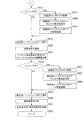
図7のフローチャートを参照して、パン操作等の動作速度が速い場合のパンニングの検出方法について説明する。パン・チルト判定部504が行うパンニング検知の判定処理では、一定周期で同一の処理が、第1軸及び第2軸に対して別々に実行される。
With reference to the flowchart of FIG. 7, a method of detecting panning when the operation speed such as pan operation is high will be described. In the panning detection determination process performed by the pan /
まず、速いパンニング判定処理が開始すると(S701)、振れ情報及び判定基準値を使用して撮像装置の姿勢がパンニング等により不安定な状態であるか否かが判定される(S702)。パン・チルト判定部504は、撮像装置の姿勢が不安定な状態であると判定した場合、S712に進んでパン検知判定処理を行う。また、撮像装置の姿勢が安定な状態であると判定された場合にはS703に進む。
First, when fast panning determination processing is started (S701), it is determined whether or not the posture of the imaging apparatus is unstable due to panning or the like using shake information and a determination reference value (S702). If the pan /
パン検知判定処理から説明すると、S712で、第1フラグ(以下、「初回パン検知フラグ」という)がセットされているか否かが判定される。初回パン検知フラグは、パン検知用の第2フラグ(以下、「パン検知フラグ」という)がセットされてから、クリアされるまでの間に複数回セットされることを防止するためのフラグである。初回パン検知フラグがセットされていなければ、S706へ移行する。また、初回パン検知フラグがセットされている場合には、S713に進む。S713では高周波振れ信号のレベルが第3閾値(「所定値3」と記す)と比較される。高周波振れ信号のレベルが所定値3以上である場合、S714に進むが、所定値3より小さい場合にはパンニング中ではないと判定され、S706へ移行する。 Explaining from the pan detection determination process, in S712, it is determined whether or not the first flag (hereinafter referred to as "first pan detection flag") is set. The initial pan detection flag is a flag for preventing the second pan detection flag (hereinafter referred to as “pan detection flag”) from being set a plurality of times after being set. . If the initial pan detection flag is not set, the process proceeds to S706. If the initial pan detection flag is set, the process proceeds to S713. In S713, the level of the high-frequency shake signal is compared with a third threshold value (denoted as “predetermined value 3”). If the level of the high-frequency shake signal is equal to or greater than the predetermined value 3, the process proceeds to S714. If it is smaller than the predetermined value 3, it is determined that panning is not being performed, and the process proceeds to S706.
S714にて、高周波向けの速いパン検知フラグ(第3フラグ)がセットされる。次のS715にて、低周波向けの速いパン検知フラグ(第4フラグ)がセットされ、さらにS716では、初回パン検知フラグがクリアされる。そして安定カウンタの値がゼロにクリアされる(S717)。安定カウンタとは、撮像装置の振れ量が所定時間に亘って小さいか否かを判断するためのカウント変数であり、S708で使用する。S717の後、S706(高周波向けの速いパンフラグのクリア判定処理)へ移行する。 In S714, a fast pan detection flag (third flag) for high frequency is set. In the next S715, a fast pan detection flag (fourth flag) for low frequency is set, and in S716, the initial pan detection flag is cleared. Then, the value of the stability counter is cleared to zero (S717). The stability counter is a count variable for determining whether or not the shake amount of the imaging apparatus is small over a predetermined time, and is used in S708. After S717, the process proceeds to S706 (fast pan flag clear determination process for high frequency).
一方、S702にて撮像装置の姿勢が安定であると判定された場合、S703に進み、パン検知終了の判定処理が行われる。S703にて高周波振れ信号が第1閾値(「所定値1」と記す)と比較される。高周波振れ信号が所定値1以下である場合、S704に進むが、所定値1を超える場合にはパンニング状態であると判定されてS706へ移行する。
On the other hand, if it is determined in S702 that the posture of the imaging apparatus is stable, the process proceeds to S703, and a pan detection end determination process is performed. In S703, the high frequency shake signal is compared with a first threshold value (denoted as "
S704では、パンニングが終了したと判定され、低周波向けの速いパン検知フラグがクリアされる。そして、初回パン検知フラグがセットされ(S705)、再度パンニングを検知した場合に備える。次のS706にて、高周波振れ信号が第2閾値(「所定値2」と記す)と比較される。高周波振れ信号が所定値2を超える場合、パンニング状態であると判定し、速いパンニング判定を終了する(S711)。 In S704, it is determined that panning has ended, and the fast pan detection flag for low frequencies is cleared. Then, the initial pan detection flag is set (S705) to prepare for the case where panning is detected again. In next step S706, the high-frequency shake signal is compared with a second threshold value (denoted as “predetermined value 2”). When the high frequency shake signal exceeds the predetermined value 2, it is determined that the panning state is set, and the fast panning determination is terminated (S711).
また、S706にて高周波振れ信号が所定値2以下の場合には、パンニング終了の条件を満たすので、S707に進む。S707にて安定カウンタの値がインクリメントにより1だけ加算される。次に、安定カウンタの値が所定値(閾値)と比較される(S708)。安定カウンタの値が所定値以上であると判定された場合、S709に進むが、所定値未満の場合には、まだパンニングが終了していないと判定されてS711へ移行する。 If the high frequency shake signal is less than or equal to the predetermined value 2 in S706, the panning end condition is satisfied, and the process proceeds to S707. In S707, the value of the stability counter is incremented by 1 by increment. Next, the value of the stability counter is compared with a predetermined value (threshold value) (S708). If it is determined that the value of the stability counter is equal to or greater than the predetermined value, the process proceeds to S709. If it is less than the predetermined value, it is determined that panning has not been completed, and the process proceeds to S711.
S708で安定カウンタの値が所定値以上になった場合、振れ状態が所定時間に亘って小さいと判断され、パンニングが終了したと判定される。この場合、高周波向けの速いパン検知フラグがクリアされ(S709)、安定カウンタに所定値がセットされる(S710)。そして、速いパンニング判定を終了する(S711)。 When the value of the stability counter becomes equal to or larger than the predetermined value in S708, it is determined that the shake state is small for a predetermined time, and it is determined that panning is completed. In this case, the fast pan detection flag for high frequency is cleared (S709), and a predetermined value is set in the stability counter (S710). Then, the fast panning determination is finished (S711).
このように、補正レンズ103の低周波の振れ目標値と高周波の振れ目標値の演算に対して別々のパン検知判定とパン検知終了判定が実行される。尚、速いチルティングの検知判定及び検知終了判定についても前記と同様に行われる。
In this manner, separate pan detection determination and pan detection end determination are executed for the calculation of the low-frequency shake target value and the high-frequency shake target value of the
図9は速いパンニング判定を説明するタイミングチャートである。高周波振れ信号の時間的変化と、低周波及び高周波向けの各パン検知フラグについてのセット及びクリアのタイミングを例示する。図9には、パンニング判定に使用する高周波振れ信号は、振れ量が上昇して所定値1、所定値2、所定値3の順に超えた後にピーク値を示してから、徐々に低下していく例を示す。パンニングの検知を行うための所定値3と、低周波向けパンニング終了判定を行うための所定値1、及び高周波向けパンニング終了判定を行うための所定値2は、「所定値3>所定値2>所定値1」の関係とする。
FIG. 9 is a timing chart for explaining fast panning determination. The time change of a high frequency shake signal and the timing of setting and clearing each pan detection flag for low frequency and high frequency are illustrated. In FIG. 9, the high-frequency shake signal used for the panning determination shows a peak value after the shake amount increases and exceeds the
各パン検知フラグは、高周波振れ信号の振れ量が所定値3に到達した時点でセットされる。つまり、高周波、低周波のパンニング検知は同じタイミングである。しかし、低周波向けパン検知フラグ(第4フラグ)は、高周波振れ信号の振れ量が低下して所定値1に達する時点でクリアされる。また高周波向けパン検知フラグ(第3フラグ)は、高周波振れ信号の振れ量が低下して所定値2に達する時点でクリアされる。パンニング終了判定については、高周波向けパン検知フラグの方が早いタイミングで判定され、低周波向けパン検知フラグは、振れ信号が十分小さくなった遅いタイミングで判定される。このように、低周波と高周波とでパンニング終了の判定タイミングには時間差がある。
Each pan detection flag is set when the shake amount of the high-frequency shake signal reaches a predetermined value 3. That is, high frequency and low frequency panning detection is at the same timing. However, the low frequency pan detection flag (fourth flag) is cleared when the shake amount of the high frequency shake signal decreases and reaches a
次に、図8のフローチャートを参照して、遅いパンニングの検出方法について説明する。パン検知の判定処理は一定周期で同一の処理が、第1軸及び第2軸に対して別々に実行される。例えば、第1軸回りの方向をピッチ方向とし、第2軸回りの方向をヨー方向とする。 Next, a slow panning detection method will be described with reference to the flowchart of FIG. In the pan detection determination process, the same process is executed separately for the first axis and the second axis at a constant cycle. For example, the direction around the first axis is the pitch direction, and the direction around the second axis is the yaw direction.
まず、遅いパンニング判定処理が開始すると(S801)、振れ情報及び判定基準値を使用して撮像装置が三脚に設置されている静止状態(以下、「三脚おき状態」という)であるか否かが判定される(S802)。三脚おき状態以外を、「非三脚状態」という。撮像装置の正位置に対して、第1軸について三脚おき状態であって、かつ第2軸について非三脚状態であると判定された場合、S803に処理を進めるが、判定条件を満たさない場合、S807に移行する。 First, when the slow panning determination process is started (S801), it is determined whether or not the imaging device is in a stationary state (hereinafter, referred to as “tripod trip state”) using the shake information and the determination reference value. It is determined (S802). A state other than a tripod is called “non-tripod state”. When it is determined that the tripod is in the alternate state with respect to the first axis and the non-tripod state is in the second axis with respect to the normal position of the imaging device, the process proceeds to S803, but the determination condition is not satisfied, The process proceeds to S807.
S803にて、第5フラグである、第1軸の遅いパン検知フラグがクリアされ、S804にて、第6フラグである、第1軸の三脚時の遅いパン検知フラグがクリアされる。さらにS805にて、第7フラグである、第2軸の遅いパン検知フラグがセットされる。S806にて、第8フラグである、第2軸の三脚時の遅いパン検知フラグがセットされる。そして遅いパンニング判定を終了する(S825)。 In S803, the fifth flag, the slow pan detection flag for the first axis, is cleared, and in S804, the slow pan detection flag for the tripod of the first axis, which is the sixth flag, is cleared. In S805, the second axis slow pan detection flag, which is the seventh flag, is set. In S806, a slow pan detection flag for the second axis tripod, which is the eighth flag, is set. Then, the slow panning determination is finished (S825).
S807にて、第2軸について三脚おき状態であって、かつ第1軸について非三脚状態であるか否かが判定される。判定条件を満たす場合、S808に進むが、判定条件を満たさない場合、S812に移行する。S808にて第1軸の遅いパン検知フラグがセットされ、S809にて第1軸の三脚時の遅いパン検知フラグがセットされる。さらにS810にて第2軸の遅いパン検知フラグがクリアされ、S811にて第2軸の三脚時の遅いパン検知フラグがクリアされ、遅いパンニング判定を終了する(S825)。 In S807, it is determined whether or not the second axis is in the tripod alternate state and the first axis is in the non-tripod state. If the determination condition is satisfied, the process proceeds to S808. If the determination condition is not satisfied, the process proceeds to S812. In S808, the slow pan detection flag for the first axis is set, and in S809, the slow pan detection flag for the first axis tripod is set. Further, the slow pan detection flag for the second axis is cleared in S810, the slow pan detection flag for the tripod of the second axis is cleared in S811, and the slow panning determination is terminated (S825).
S802、S807にて、片軸が三脚おき状態であり、かつ、もう片軸がパンニング状態であると判定されなかった場合、パン・チルト判定部504は、両軸にて三脚おき状態であるか、または手持ち撮影状態であると判断し、S812に処理を移行する。S812では、振れ信号のレベルが所定値4と比較され、所定値4以上であるか否かが判定される。振れ信号のレベルが所定値4以上の場合、ゆっくりした遅いパンニング状態の可能性があると判断され、S813に進み、所定値4未満の場合にはS818に移行する。
In S802 and S807, if it is not determined that one axis is in the tripod state and the other axis is in the panning state, is the pan /
S813では、遅いパン検知カウンタの値に1が加算される(インクリメント)。次に、遅いパン検知カウンタの値が所定値(閾値)以上であるか否かが判定される(S814)。遅いパン検知カウンタの値が、所定値未満の場合、遅いパンニング判定を終了する(S825)。また、S814にて遅いパン検知カウンタの値が所定値以上の場合、S815に進む。この場合、所定時間中に連続して、ある振れが発生していると判断され、遅いパン検知フラグがセットされる(S815)。遅いパン検知カウンタに所定値がセットされる(S816)。さらに遅いパン検知解除カウンタの値がゼロにクリアされ(S817)、遅いパン検知フラグのクリアに備えた後、遅いパンニング判定を終了する(S825)。 In S813, 1 is added to the value of the slow pan detection counter (increment). Next, it is determined whether or not the value of the slow pan detection counter is greater than or equal to a predetermined value (threshold) (S814). If the value of the slow pan detection counter is less than the predetermined value, the slow panning determination is terminated (S825). If the value of the slow pan detection counter is greater than or equal to the predetermined value in S814, the process proceeds to S815. In this case, it is determined that a certain shake has occurred continuously during a predetermined time, and a slow pan detection flag is set (S815). A predetermined value is set in the slow pan detection counter (S816). Further, the value of the slow pan detection cancellation counter is cleared to zero (S817), and after preparing for clearing of the slow pan detection flag, the slow panning determination is terminated (S825).
一方、S818では振れ信号のレベルが所定値5以下であるか否かが判定される。判定条件を満たさない場合、撮像装置の振れが大きく、遅いパンニングが終了していないと判断され、S825へ進む。また振れ信号のレベルが所定値5以下である場合には、S819に処理を進める。この場合、遅いパン検知解除カウンタのインクリメントが行われる(S819)。次に、遅いパン検知解除カウンタの値が所定値以上であるか否かが判定される(S820)。判定条件を満たさない場合、S825へ進んで処理を終了する。また、判定条件を満たす場合には、所定時間に亘り連続して振れが小さいと判断され、S821に進み、遅いパン検知フラグがクリアされる。さらに、S822で遅いパン検知解除カウンタに所定値がセットされた後、遅いパン検知カウンタの値がゼロにクリアされる(S823)。S824にて三脚時の遅いパン検知フラグがクリアされた後、遅いパンニング判定処理を終了する。 On the other hand, in S818, it is determined whether or not the level of the shake signal is a predetermined value 5 or less. If the determination condition is not satisfied, it is determined that the shake of the imaging apparatus is large and the slow panning is not completed, and the process proceeds to S825. If the level of the shake signal is equal to or less than the predetermined value 5, the process proceeds to S819. In this case, the slow pan detection cancellation counter is incremented (S819). Next, it is determined whether or not the value of the slow pan detection cancellation counter is greater than or equal to a predetermined value (S820). If the determination condition is not satisfied, the process proceeds to S825 to end the process. If the determination condition is satisfied, it is determined that the shake is small continuously for a predetermined time, and the process proceeds to S821, where the slow pan detection flag is cleared. Further, after a predetermined value is set in the slow pan detection cancellation counter in S822, the value of the slow pan detection counter is cleared to zero (S823). After the slow pan detection flag for the tripod is cleared in S824, the slow panning determination process is terminated.
このように、遅いパンニング判定では、所定時間に亘って連続して、所定値4以上の大きな振れ信号を検出した場合にフラグがセットされる。また所定時間に亘って連続して所定値5以下の振れ信号の状態が継続したことを検出した場合、フラグがクリアされる。パンニング検知判定に用いる所定値4と、パンニング検知解除の判定に用いる所定値5は、「所定値4>所定値5」の関係を満たす。 Thus, in the slow panning determination, a flag is set when a large shake signal of a predetermined value 4 or more is detected continuously for a predetermined time. Further, when it is detected that the state of the shake signal having a predetermined value of 5 or less continues for a predetermined time, the flag is cleared. The predetermined value 4 used for the panning detection determination and the predetermined value 5 used for the panning detection cancellation determination satisfy the relationship of “predetermined value 4> predetermined value 5”.
手持ち状態に比べて三脚おき状態でのパンニング動作では、撮像装置が振れ状態にないため、パンニング直後の揺り戻しが目立ちやすい。この場合、手持ち状態と同様に、三脚おき状態でのパンニング検出を、所定時間の振れ状態によって判定したのでは検知が遅すぎる可能性がある。そこで、片軸にて三脚おき状態であって、もう片軸にてパンニング操作が行われた場合には、即座に遅いパンニングと判定される。これにより、三脚おき状態でのパンニングによる揺り戻しを抑えることができる。尚、遅いチルティングの検知判定及び検知終了判定についても前記と同様に行われる。 Compared to the hand-held state, in the panning operation in the state where the tripod is placed, the image pickup apparatus is not in a shake state, so that the swingback immediately after the panning is conspicuous. In this case, as in the case of the hand-held state, it may be too late to detect the panning detection in the every other tripod state based on the shake state for a predetermined time. Therefore, when the tripod is on the other axis and the panning operation is performed on the other axis, it is immediately determined that the panning is slow. As a result, it is possible to suppress rocking back due to panning in the state of every tripod. The slow tilting detection determination and detection end determination are performed in the same manner as described above.
次に、図4と、図5及び図6のフローチャートを参照して、速いパンニング及び遅いパンニング時の低周波、高周波の振れ補正演算について説明する。この振れ補正制御演算は一定周期で実行される。 Next, low-frequency and high-frequency shake correction computations during fast panning and slow panning will be described with reference to FIG. 4 and the flowcharts of FIGS. 5 and 6. This shake correction control calculation is executed at a constant cycle.
処理が開始すると(S601)、HPF501は、振れセンサ201から振れ信号を取得し(S602)、その低域周波数成分を除去する(S603)。次に、減算部517は、振れ信号からHPF501の出力を減算し(S604)、振れ信号に含まれる低域のオフセット成分が算出される。S605にて防振制御(像振れ補正制御)の開始が判定される。防振制御の開始前には、S633に進み、S604で算出された低域のオフセット成分の値がオフセット記憶部502に保持されることで更新される。そして、処理を終了する。
When the process starts (S601), the
S605にて防振制御が開始すると、S606に進む。この場合、S604で算出された低域のオフセット成分の値がオフセット記憶部502に保持され、更新を停止する。これにより、制御開始時のオフセット成分を固定値として保持することができる。次に、減算部518は、振れ信号から、オフセット記憶部502に記憶されたオフセット値を減算し(S607)、オフセット除去後の値を保持する(S608)。つまり振れ信号のオフセット演算を停止することで、HPF501による低域成分除去を行わない振れ信号が、像振れ補正に使用されることになる。こうすることで、カットオフ周波数の低いデジタルフィルタ演算による揺れ戻し動作を抑制できる。
When the image stabilization control is started in S605, the process proceeds to S606. In this case, the value of the low frequency offset component calculated in S604 is held in the offset
パン・チルト判定部504は、撮像装置がパンニング中またはチルティング中であるか否かを判定する(S609)。以下、パンニング判定を例にして説明する(具体的な処理については図6から図8参照)。撮像装置がパンニング中であると判定された場合、S611に進み、パンニング中でないと判定された場合、S610に移行する。
The pan /
S611でパン・チルト判定部504は、LPF508の中間値から所定値を減算する。これは、パンニング動作時の大きな振れに対して、LPF508の中間値が増加しすぎるのを抑制するためである。そしてLPF508は演算を行い(S610)、演算値を保持することで(S612)、振れ量の低周波成分を抽出する。次にオフセット算出部514は、低周波LPF511の入力端にてオフセットが発生しないように、オフセット量を算出する(S614)。減算部519は、LPF508の出力である、振れ量の低周波成分から、オフセット量を減算する(S616)。そして図6のS617に処理を進める。
In step S <b> 611, the pan /
次のS617にて、パン・チルト判定部504は、再度パンニング中であるか否かを判定する。撮像装置がパンニング中である場合、S619に進み、パンニング中でない場合、S618に移行する。S619で低周波リミッタ510は、低周波LPF511への入力が所定値以上にならないように制限する。パン・チルト判定部504は、補正レンズ103の目標位置と駆動中心位置との距離に基づいて、補正レンズ103が駆動範囲から外れないように低周波LPF511のカットオフ周波数を変更して高く設定する(S620)。さらにパン・チルト判定部504は、低周波LPF511の中間値から所定値を減算することで、中間値の増加を抑える演算を行う(S621)。
In next step S617, the pan /
S618で低周波LPF511は演算を行って演算結果を保持し(S622)、低周波の振れ量に対する補正レンズ103の目標位置を算出する。次にS608、S612で保持しておいたオフセット除去後の振れ量から、LPF508の演算値が減算され(S623)、振れ量の高周波成分が抽出される。S624にてパン・チルト判定部504は、パンニング中であるか否かを判定する。撮像装置がパンニング中の場合、S627に進み、パンニング中でない場合、S625に移行する。
In step S618, the
S627で高周波リミッタ506は、高周波LPF507への入力を制限する。パン・チルト判定部504は、補正レンズ103の目標位置と駆動中心位置との距離に基づいて、補正レンズ103が駆動範囲から外れないように、高周波LPF507のカットオフ周波数を高周波側へ変更する(S628)。さらにパン・チルト判定部504は、高周波LPF507の中間値から所定値を減算することで、中間値の増加を抑える演算を行う(S629)。S625で高周波LPF507は演算を行い、演算結果を保持する(S630)。高周波の振れ量に対する補正レンズ103の目標位置が算出される。S631で加算部520は、S622,S630でそれぞれ保持された、低周波の振れ量に対する補正レンズ103の目標位置と、高周波の振れ量に対する補正レンズ103の目標位置を加算する。こうして、最終的な補正レンズの目標位置が算出され、S632で処理を終える。
In step S627, the
このように演算された目標位置に対して、補正レンズ103の位置が追従するようにフィードバック制御が実行される結果、撮像装置に加わる手振れ等の影響が除去される。振れ信号を周波数で分割するLPF508のカットオフ周波数は、手振れの影響が大きい周波数帯が高周波側に含まれるように決定される。例えば、振れ信号が主に3Hz〜5Hz程度の周波数に多く含まれる場合には、カットオフ周波数は少なくとも3Hz以下に設定される。
As a result of performing feedback control so that the position of the
本実施形態では、パンニング(またはチルティング)の速度を閾値と比較し、閾値より大きい速いパンニングと閾値以下の遅いパンニングの検出を別々に行い、検出結果に応じてフィルタ演算の処理内容を変更する。また、振れ信号を低周波と高周波に分割して、2種類の検出における各パンニング速度条件に応じて、低周波の振れ、高周波の振れを別々に処理することで、補正レンズの目標位置が算出される。速いパンニングの場合、低周波、高周波の振れ補正レンズ目標値ともに所定値(例えば、ゼロまたはゼロ近傍)に収束させる処理が実行される。低周波、高周波ともに補正レンズの目標位置が可動範囲の中心にセンタリングされる。その後、振れ信号(角速度信号)から補正レンズ目標位置である振れ角度信号を算出するための積分演算が行われる。低周波側の演算よりも高周波側の演算を先に開始させることで、パンニング直後の振れ補正が行われていない時間を短くし、またパンニングによる揺れ戻しを抑制できる。 In this embodiment, the panning (or tilting) speed is compared with a threshold, fast panning larger than the threshold and slow panning below the threshold are separately detected, and the processing content of the filter operation is changed according to the detection result. . In addition, the target position of the correction lens is calculated by dividing the shake signal into low frequency and high frequency, and separately processing low frequency shake and high frequency shake according to each panning speed condition in the two types of detection. Is done. In the case of fast panning, processing is performed to converge both the low-frequency and high-frequency shake correction lens target values to predetermined values (for example, zero or near zero). The target position of the correction lens is centered at the center of the movable range for both low and high frequencies. Thereafter, an integration operation for calculating a shake angle signal that is a correction lens target position from the shake signal (angular velocity signal) is performed. By starting the calculation on the high frequency side earlier than the calculation on the low frequency side, the time during which the shake correction immediately after panning is not performed can be shortened, and the shake back due to panning can be suppressed.
一方、パンニング速度が閾値以下で遅い場合には、補正レンズが駆動可能範囲外に駆動されやすい低周波のみについて補正レンズの目標位置を所定値に収束させる処理が実行される。この場合、補正レンズに係る高周波の目標位置を収束させる制御は行わない。高周波側の振れ補正を継続させることで、パンニング時の像振れ補正効果の低下を抑えることができる。また、手持ち撮影時と、カメラが三脚等に設置された静止状態(三脚おき状態等)でのパンニングとで、遅いパンニングの判定方法が変更される。よって、揺り戻しが目立ちやすい三脚おき状態等にて、パンニング動作後の揺れ戻しによる撮影画像の変化を低減し、違和感のない画像を出力することができる。 On the other hand, when the panning speed is lower than the threshold value and slow, a process for converging the target position of the correction lens to a predetermined value is executed only for low frequencies where the correction lens is likely to be driven out of the driveable range. In this case, control for converging the high frequency target position related to the correction lens is not performed. By continuing the high-frequency shake correction, it is possible to suppress a reduction in the image shake correction effect during panning. In addition, the slow panning determination method is changed between hand-held shooting and panning in a stationary state where the camera is installed on a tripod or the like (triple tripping state or the like). Therefore, it is possible to reduce the change in the captured image due to the swing back after the panning operation and output an image without a sense of incongruity in a tripod state where the swing back is easily noticeable.
本実施形態によれば、パン操作等による大きな振れが生じても良好な像振れ補正を実現できる。尚、本実施形態では、振れ検出信号を高周波成分と低周波成分の2種類に分割する例を説明したが、3以上の周波数成分に分割する構成にも本発明を適用可能である。 According to the present embodiment, good image blur correction can be realized even if a large shake due to a pan operation or the like occurs. In the present embodiment, the example in which the shake detection signal is divided into two types of the high frequency component and the low frequency component has been described. However, the present invention can also be applied to a configuration in which the shake detection signal is divided into three or more frequency components.
[その他の実施形態]
また、本発明は、以下の処理を実行することによっても実現される。即ち、上述した実施形態の機能を実現するソフトウェア(プログラム)を、ネットワーク又は各種記憶媒体を介してシステム或いは装置に供給し、そのシステム或いは装置のコンピュータ(またはCPUやMPU等)がプログラムを読み出して実行する処理である。この場合、そのプログラム、及び該プログラムを格納したコンピュータ読み取り可能な記憶媒体は本発明を構成することになる。
[Other Embodiments]
The present invention can also be realized by executing the following processing. That is, software (program) that realizes the functions of the above-described embodiments is supplied to a system or apparatus via a network or various storage media, and a computer (or CPU, MPU, or the like) of the system or apparatus reads the program. It is a process to be executed. In this case, the program and a computer-readable storage medium storing the program constitute the present invention.
103 補正レンズ
201,202 振れセンサ
203,204 振れ補正制御部
205,206 レンズ位置制御部
207,208 ドライブ部
504 パン・チルト判定部
507 高周波LPF
508 LPF
511 低周波LPF
515 減算部
516 三脚判定部
520 加算部
103
508 LPF
511 LPF
515
Claims (12)
前記振れ検出信号からパンニングまたはチルティングが判定された場合、パンニングまたはチルティングの速度を検出し、検出した前記速度に基づいて、前記分割された複数の周波数成分に対するそれぞれのフィルタ演算のカットオフ周波数または当該フィルタ演算にて算出される中間値を独立に変更し、前記フィルタ演算を行った信号を合成して振れ補正手段の制御信号を生成する制御手段と、を備え、
前記制御手段は、パンニングまたはチルティングの速度が閾値以下である場合、前記振れ補正手段に係る低周波の目標位置を収束させ、前記振れ補正手段に係る高周波の目標位置を収束させる制御を行わず、パンニングまたはチルティングの速度が前記閾値より大きい場合、前記振れ補正手段に係る低周波及び高周波の目標位置をともに収束させることを特徴とする像振れ補正装置。 A dividing means for dividing the shake detection signal into a plurality of frequency components;
When panning or tilting is determined from the shake detection signal, the panning or tilting speed is detected, and based on the detected speed, the cutoff frequency of each filter operation for the divided frequency components Or a control means for independently changing the intermediate value calculated in the filter calculation, and synthesizing the signals subjected to the filter calculation to generate a control signal of the shake correction means ,
The control means does not perform control to converge the low frequency target position related to the shake correction means and converge the high frequency target position related to the shake correction means when the panning or tilting speed is equal to or less than a threshold value. , if the speed of the panning or tilting is larger than the threshold value, the image blur correction apparatus, characterized in Rukoto both converges the target position of the low and high frequency according to the shake correction means.
前記制御手段は、
パンニングまたはチルティングの速度を判定する判定手段と、
前記高周波成分を積分処理するとともにフィルタ演算の収束時定数が可変の第1ローパスフィルタと、
前記低周波成分を積分処理するとともにフィルタ演算の収束時定数が可変の第2ローパスフィルタと、
前記判定手段により判定されたパンニングまたはチルティングの速度により前記カットオフ周波数または中間値が変更される、前記第1ローパスフィルタおよび第2ローパスフィルタの出力信号を加算して、前記振れ補正手段の目標位置の制御信号を出力する合成手段を有することを特徴とする請求項1に記載の像振れ補正装置。 The dividing unit divides the shake detection signal into a low frequency component and a high frequency component,
The control means includes
A determination means for determining a panning or tilting speed;
A first low-pass filter that integrates the high-frequency component and has a variable convergence time constant of the filter operation;
A second low-pass filter that integrates the low-frequency component and has a variable convergence time constant of the filter operation;
The cut-off frequency or the intermediate value is changed according to the panning or tilting speed determined by the determination means, and the output signals of the first low-pass filter and the second low-pass filter are added, and the target of the shake correction means The image blur correction apparatus according to claim 1, further comprising a combining unit that outputs a position control signal.
前記低周波成分を抽出する第3ローパスフィルタと、
前記振れ検出信号から、前記第3ローパスフィルタが抽出する前記低周波成分を減算して前記高周波成分を出力する減算手段を備えることを特徴とする請求項2に記載の像振れ補正装置。 The dividing means includes
A third low pass filter for extracting the low frequency component;
3. The image blur correction device according to claim 2, further comprising subtracting means for subtracting the low frequency component extracted by the third low-pass filter from the shake detection signal and outputting the high frequency component.
前記振れ検出信号を取得して前記補正レンズの目標位置を決定して、前記補正レンズの位置を前記目標位置に収束させるフィードバック制御を行う位置制御手段を備えることを特徴とする請求項9に記載の撮像装置。 The shake correction means is a correction lens that can move in a direction different from the optical axis of the photographing optical system,
Determines the target position of the correction lens to obtain the shake detection signal, wherein the position of the correcting lens to claim 9, characterized in that it comprises a position control means for performing the cause feedback control converges to the target position Imaging device.
前記三脚判定手段によりピッチ方向およびヨー方向にて撮像装置が静止状態でないと判定された場合、前記制御手段はフィルタ演算の入力を制限することを特徴とする請求項10に記載の撮像装置。 A tripod determining means for acquiring the shake detection signal and determining whether the imaging apparatus is in a stationary state installed on a tripod;
11. The imaging apparatus according to claim 10 , wherein when the imaging apparatus is determined not to be stationary in the pitch direction and the yaw direction by the tripod determination unit, the control unit limits input of filter calculation.
分割手段が振れ検出信号を複数の周波数成分に分割する工程と、
制御手段により、前記振れ検出信号を取得してパンニングまたはチルティングが判定された場合、パンニングまたはチルティングの速度を検出し、検出した前記速度に基づいて、前記分割された複数の周波数成分に対するそれぞれのフィルタ演算のカットオフ周波数または当該フィルタ演算にて算出される中間値を独立に変更する工程と、
前記制御手段により、前記フィルタ演算を行った信号を合成して振れ補正手段の制御信号を生成する工程と、を有し、
前記制御手段は、パンニングまたはチルティングの速度が閾値以下である場合、前記振れ補正手段に係る低周波の目標位置を収束させ、前記振れ補正手段に係る高周波の目標位置を収束させる制御を行わず、パンニングまたはチルティングの速度が前記閾値より大きい場合、前記振れ補正手段に係る低周波及び高周波の目標位置をともに収束させることを特徴とする制御方法。 A control method executed by the image shake correction apparatus,
A dividing unit that divides the shake detection signal into a plurality of frequency components;
When panning or tilting is determined by acquiring the shake detection signal by the control means, a panning or tilting speed is detected, and each of the divided frequency components is detected based on the detected speed. Independently changing the cutoff frequency of the filter operation or the intermediate value calculated by the filter operation;
Wherein the control means, have a, generating a control signal of the signal combining to shake correcting means performing the filtering operation,
The control means does not perform control to converge the low frequency target position related to the shake correction means and converge the high frequency target position related to the shake correction means when the panning or tilting speed is equal to or less than a threshold value. , if the speed of the panning or tilting is larger than the threshold value, the control method comprising Rukoto both converges the target position of the low and high frequency according to the shake correction means.
Priority Applications (3)
| Application Number | Priority Date | Filing Date | Title |
|---|---|---|---|
| JP2013257050A JP6351246B2 (en) | 2013-12-12 | 2013-12-12 | Image shake correction apparatus, control method therefor, optical apparatus, and imaging apparatus |
| US14/557,689 US9749533B2 (en) | 2013-12-12 | 2014-12-02 | Image shake correcting device and control method therefor, optical apparatus, and image pickup apparatus |
| CN201410758373.5A CN104714353B (en) | 2013-12-12 | 2014-12-10 | Image dithering correcting equipment and its control method, Optical devices and camera device |
Applications Claiming Priority (1)
| Application Number | Priority Date | Filing Date | Title |
|---|---|---|---|
| JP2013257050A JP6351246B2 (en) | 2013-12-12 | 2013-12-12 | Image shake correction apparatus, control method therefor, optical apparatus, and imaging apparatus |
Publications (3)
| Publication Number | Publication Date |
|---|---|
| JP2015114534A JP2015114534A (en) | 2015-06-22 |
| JP2015114534A5 JP2015114534A5 (en) | 2017-01-19 |
| JP6351246B2 true JP6351246B2 (en) | 2018-07-04 |
Family
ID=53370022
Family Applications (1)
| Application Number | Title | Priority Date | Filing Date |
|---|---|---|---|
| JP2013257050A Active JP6351246B2 (en) | 2013-12-12 | 2013-12-12 | Image shake correction apparatus, control method therefor, optical apparatus, and imaging apparatus |
Country Status (3)
| Country | Link |
|---|---|
| US (1) | US9749533B2 (en) |
| JP (1) | JP6351246B2 (en) |
| CN (1) | CN104714353B (en) |
Families Citing this family (12)
| Publication number | Priority date | Publication date | Assignee | Title |
|---|---|---|---|---|
| JP6482197B2 (en) | 2014-07-16 | 2019-03-13 | キヤノン株式会社 | Image shake correction apparatus, control method thereof, and imaging apparatus |
| JP6587534B2 (en) * | 2015-12-14 | 2019-10-09 | キヤノン株式会社 | Angle of view control device, imaging device, and angle of view control program |
| CN109791342B (en) | 2016-09-15 | 2021-02-02 | 富士胶片株式会社 | Image pickup apparatus, and shake detection apparatus, shake correction apparatus, and shake detection method therefor |
| WO2018070468A1 (en) | 2016-10-13 | 2018-04-19 | 富士フイルム株式会社 | Shake correction device, imaging device, and shake correction method |
| US10805539B2 (en) * | 2016-12-02 | 2020-10-13 | Hangzhou Hikvision Digital Technology Co., Ltd. | Anti-shake method for camera and camera |
| KR20180070264A (en) * | 2016-12-16 | 2018-06-26 | 삼성전자주식회사 | Obtaining method for Panning shot image and Electronic device supporting the same |
| CN106998426B (en) * | 2017-03-01 | 2020-07-14 | 惠州Tcl移动通信有限公司 | Dynamic photographing processing method and system based on mobile terminal |
| US10165170B2 (en) * | 2017-03-06 | 2018-12-25 | Semiconductor Components Industries, Llc | Methods and apparatus for autofocus |
| JP6869771B2 (en) * | 2017-03-30 | 2021-05-12 | 日本電産サンキョー株式会社 | Optical unit with runout correction function |
| JP2020056953A (en) * | 2018-10-03 | 2020-04-09 | キヤノン株式会社 | Anti-shake device, image processing apparatus, and detection method |
| JP7150555B2 (en) * | 2018-10-16 | 2022-10-11 | キヤノン株式会社 | Image blur correction device and its control method, imaging device |
| CN111866395B (en) * | 2020-08-07 | 2022-05-13 | 苏州臻迪智能科技有限公司 | Stability augmentation processing module, unmanned aerial vehicle camera system and image stability augmentation processing method |
Family Cites Families (19)
| Publication number | Priority date | Publication date | Assignee | Title |
|---|---|---|---|---|
| JP2000039640A (en) * | 1998-07-24 | 2000-02-08 | Canon Inc | Image pickup device and shake correction device and method |
| JP2002158927A (en) * | 2000-11-21 | 2002-05-31 | Hitachi Kokusai Electric Inc | Image signal synthesizer |
| JP2004215189A (en) * | 2003-01-08 | 2004-07-29 | Sony Corp | Blurring compensation device and imaging apparatus having the blurring compensation device |
| US7486879B2 (en) * | 2004-05-11 | 2009-02-03 | Fujinon Corporation | Image blur correcting device |
| JP2006113264A (en) | 2004-10-14 | 2006-04-27 | Fujinon Corp | Image blur correcting apparatus |
| JP4552782B2 (en) * | 2005-07-06 | 2010-09-29 | コニカミノルタオプト株式会社 | Shake detection device, shake correction device, and imaging device |
| JP4306679B2 (en) * | 2005-12-28 | 2009-08-05 | ソニー株式会社 | Shake detection device, shake correction device, imaging device |
| JP4900939B2 (en) * | 2006-11-28 | 2012-03-21 | キヤノン株式会社 | Method for controlling imaging apparatus |
| JPWO2008117584A1 (en) * | 2007-03-23 | 2010-07-15 | 株式会社東芝 | Camera shake correction apparatus, imaging apparatus, camera shake correction program, imaging program, camera shake correction method, and imaging method |
| JP4969508B2 (en) * | 2008-04-25 | 2012-07-04 | オンセミコンダクター・トレーディング・リミテッド | Vibration correction control circuit and imaging apparatus equipped with the same |
| JP4518197B2 (en) | 2008-06-20 | 2010-08-04 | ソニー株式会社 | Imaging apparatus, image blur correction method, and program |
| JP5230398B2 (en) | 2008-12-19 | 2013-07-10 | キヤノン株式会社 | Imaging apparatus and control method thereof |
| JP2011118073A (en) | 2009-12-02 | 2011-06-16 | Panasonic Corp | Image blur correcting apparatus |
| JP5441679B2 (en) | 2009-12-28 | 2014-03-12 | キヤノン株式会社 | Imaging device |
| JP5501119B2 (en) * | 2010-06-29 | 2014-05-21 | キヤノン株式会社 | Imaging apparatus and control method thereof |
| JP5744442B2 (en) * | 2010-08-30 | 2015-07-08 | キヤノン株式会社 | Optical device and control method of optical device |
| JP5869812B2 (en) | 2011-09-13 | 2016-02-24 | キヤノン株式会社 | Image blur correction apparatus, image pickup apparatus including the same, and method for controlling image blur correction apparatus |
| US9300873B2 (en) * | 2012-06-22 | 2016-03-29 | Apple Inc. | Automated tripod detection and handling in video stabilization |
| JP5539490B2 (en) * | 2012-12-28 | 2014-07-02 | キヤノン株式会社 | Image shake correction apparatus, optical apparatus including the same, imaging apparatus, and image shake correction apparatus control method |
-
2013
- 2013-12-12 JP JP2013257050A patent/JP6351246B2/en active Active
-
2014
- 2014-12-02 US US14/557,689 patent/US9749533B2/en active Active
- 2014-12-10 CN CN201410758373.5A patent/CN104714353B/en active Active
Also Published As
| Publication number | Publication date |
|---|---|
| JP2015114534A (en) | 2015-06-22 |
| US20150172546A1 (en) | 2015-06-18 |
| CN104714353A (en) | 2015-06-17 |
| CN104714353B (en) | 2017-09-22 |
| US9749533B2 (en) | 2017-08-29 |
Similar Documents
| Publication | Publication Date | Title |
|---|---|---|
| JP6351246B2 (en) | Image shake correction apparatus, control method therefor, optical apparatus, and imaging apparatus | |
| JP5869812B2 (en) | Image blur correction apparatus, image pickup apparatus including the same, and method for controlling image blur correction apparatus | |
| JP6351247B2 (en) | Image shake correction apparatus, control method therefor, optical apparatus, and imaging apparatus | |
| JP6074298B2 (en) | Imaging apparatus, image processing apparatus, and control method thereof | |
| JP6242145B2 (en) | Image shake correction apparatus, control method thereof, and imaging apparatus | |
| JP6600163B2 (en) | Image blur correction apparatus and control method thereof | |
| JP6530602B2 (en) | Image pickup apparatus and control method thereof | |
| JP6448184B2 (en) | Image blur correction apparatus and control method thereof | |
| JP6465560B2 (en) | Image blur correction apparatus, control method therefor, program, and storage medium | |
| JP6423658B2 (en) | Imaging apparatus, control method therefor, program, and storage medium | |
| JP2015102775A (en) | Image tremor correction device and control method of the same | |
| JP6558891B2 (en) | Image shake correction apparatus and imaging apparatus | |
| US9811891B2 (en) | Image shake correction device, optical apparatus, imaging apparatus, and control method | |
| JP6482197B2 (en) | Image shake correction apparatus, control method thereof, and imaging apparatus | |
| JP2012128202A (en) | Optical instrument and imaging device with the same and control method for optical instrument | |
| JP6173134B2 (en) | Image blur correction apparatus and control method thereof | |
| JP6395401B2 (en) | Image shake correction apparatus, control method therefor, optical apparatus, and imaging apparatus | |
| JP2017032653A (en) | Image blur correction device, control method thereof, imaging apparatus, and optical apparatus | |
| JP6742819B2 (en) | Image blur correction device, optical device, imaging device, and control method | |
| JP5967885B2 (en) | Optical apparatus, imaging apparatus including the same, and control method of optical apparatus | |
| JP5746775B2 (en) | Optical apparatus and control method thereof |
Legal Events
| Date | Code | Title | Description |
|---|---|---|---|
| A521 | Request for written amendment filed |
Free format text: JAPANESE INTERMEDIATE CODE: A523 Effective date: 20161201 |
|
| A621 | Written request for application examination |
Free format text: JAPANESE INTERMEDIATE CODE: A621 Effective date: 20161201 |
|
| A977 | Report on retrieval |
Free format text: JAPANESE INTERMEDIATE CODE: A971007 Effective date: 20170818 |
|
| A131 | Notification of reasons for refusal |
Free format text: JAPANESE INTERMEDIATE CODE: A131 Effective date: 20170905 |
|
| A521 | Request for written amendment filed |
Free format text: JAPANESE INTERMEDIATE CODE: A523 Effective date: 20171101 |
|
| TRDD | Decision of grant or rejection written | ||
| A01 | Written decision to grant a patent or to grant a registration (utility model) |
Free format text: JAPANESE INTERMEDIATE CODE: A01 Effective date: 20180508 |
|
| A61 | First payment of annual fees (during grant procedure) |
Free format text: JAPANESE INTERMEDIATE CODE: A61 Effective date: 20180605 |
|
| R151 | Written notification of patent or utility model registration |
Ref document number: 6351246 Country of ref document: JP Free format text: JAPANESE INTERMEDIATE CODE: R151 |