JP6350947B2 - lighting equipment - Google Patents
lighting equipment Download PDFInfo
- Publication number
- JP6350947B2 JP6350947B2 JP2014209999A JP2014209999A JP6350947B2 JP 6350947 B2 JP6350947 B2 JP 6350947B2 JP 2014209999 A JP2014209999 A JP 2014209999A JP 2014209999 A JP2014209999 A JP 2014209999A JP 6350947 B2 JP6350947 B2 JP 6350947B2
- Authority
- JP
- Japan
- Prior art keywords
- base
- light source
- plate
- base portion
- source unit
- Prior art date
- Legal status (The legal status is an assumption and is not a legal conclusion. Google has not performed a legal analysis and makes no representation as to the accuracy of the status listed.)
- Active
Links
Images


Description
本発明は、照明器具に関し、特に、器具本体に対して光源ユニットが着脱可能に取り付けられる照明器具に関する。 The present invention relates to a lighting fixture, and more particularly to a lighting fixture in which a light source unit is detachably attached to a fixture body.
従来例として、特許文献1記載の照明器具を例示する。この従来例は、天井材に設けた埋込孔を通して天井裏に設置される天井埋込型の照明器具であり、吊ボルトを用いて天井裏に設置される支持部材と、支持部材に取り付けられる反射板と、反射板に対して着脱自在に取り付けられる光源ユニットとを備える。
As a conventional example, a lighting apparatus described in
光源ユニットは、2個のLED基板と、LED基板が取り付けられる取付部材と、LED基板を覆うようにして取付部材に取り付けられるカバー部材と、LED基板に所定の点灯電力を供給する電源装置とを有する。LED基板は、前後方向に長い矩形板状に形成されたプリント基板からなり、プリント基板の下面には複数のLED(発光ダイオード)が前後方向(長手方向)に沿って実装されている。 The light source unit includes two LED substrates, an attachment member to which the LED substrate is attached, a cover member attached to the attachment member so as to cover the LED substrate, and a power supply device that supplies predetermined lighting power to the LED substrate. Have. The LED board is a printed board formed in a rectangular plate shape that is long in the front-rear direction, and a plurality of LEDs (light emitting diodes) are mounted on the lower surface of the printed board along the front-rear direction (longitudinal direction).
反射板は、板金に曲げ加工を施すことで長尺且つ下面が開口する扁平な箱状に形成される。反射板の底面部には、光源ユニットを収容するための矩形の収容凹部が反射板の全長に亘って設けられている。また、反射板の開口端縁には、側方に延出する鍔部が全周に亘って設けられており、天井裏に設置された支持部材に反射板を取り付けた状態では、鍔部が天井材の下面に接している。つまり、特許文献1記載の従来例では、反射板により器具本体が構成されている。
The reflecting plate is formed into a flat box shape having a long and open bottom by bending the sheet metal. A rectangular accommodating recess for accommodating the light source unit is provided on the bottom surface of the reflecting plate over the entire length of the reflecting plate. Moreover, the opening edge of the reflecting plate is provided with a flange extending laterally over the entire circumference, and when the reflecting plate is attached to the support member installed on the back of the ceiling, the flange is It is in contact with the lower surface of the ceiling material. That is, in the conventional example described in
また、光源ユニットの取付部材には、係止金具及び係止ばねが取り付けられている。係止金具は、矩形板状の金具本体と、金具本体の片側の端縁から側方に延出する矩形板状の係止板とを有する。また、係止板の先端には、引掛け部が設けられている。さらに、金具本体には、係止ばねを保持するための保持部と、係止ばねの一方の腕部が係止される係止部とが設けられている。 Further, a locking member and a locking spring are mounted on the mounting member of the light source unit. The locking metal fitting has a rectangular plate-shaped metal fitting main body and a rectangular plate-shaped locking plate that extends laterally from one edge of the metal fitting main body. A hooking portion is provided at the tip of the locking plate. Furthermore, the metal fitting body is provided with a holding portion for holding the locking spring and a locking portion where one arm portion of the locking spring is locked.
係止ばねは、ねじりコイルばねからなる基端部と、基端部の両端から互いに離れる方向に延設された一対の腕部とを有する。この係止ばねは、基端部が係止金具の保持部に保持され、さらに一方の腕部が係止部に係止された状態で係止金具に取り付けられる。そして、これらの係止金具及び係止ばねは、取付部材の長手方向における両端寄りの位置に、取付ねじを用いてそれぞれ1組ずつ取り付けられる。 The locking spring has a base end portion made of a torsion coil spring and a pair of arm portions extending in directions away from both ends of the base end portion. This locking spring is attached to the locking metal fitting in a state where the base end portion is held by the holding portion of the locking metal fitting and one arm portion is locked to the locking portion. Each of these locking metal fittings and locking springs is attached to a position near both ends in the longitudinal direction of the mounting member by using a mounting screw.
一方、器具本体には、係止ばねの腕部が係止される係止金具が取り付けられている。この係止金具は、器具本体の底面部に取り付けるための取付片と、係止ばねの腕部を係止するための係止片とを有し、側面視の形状がU字状に形成されている。そして、この係止金具は、取付ねじを用いて器具本体の底面部に取り付けられる。 On the other hand, a lock fitting for locking the arm portion of the lock spring is attached to the instrument body. This locking metal fitting has a mounting piece for mounting on the bottom surface portion of the instrument body and a locking piece for locking the arm portion of the locking spring, and the shape of the side view is formed in a U shape. ing. And this latching metal fitting is attached to the bottom face part of an instrument main body using an attachment screw.
光源ユニットは、器具本体の収納凹部の側面に設けられる挿通孔に係止金具の係止板がそれぞれ挿入され、各係止板の引掛部が挿通孔の端縁に係止されることで器具本体に吊り下げられる。そして、係止ばねの腕部の先端部分が、係止金具の係止片にそれぞれ係止された後、光源ユニットが回転しながら持ち上げられると、各係止ばねの腕部の先端に設けられた引掛部が、器具本体側の係止金具の係止片に設けられた内側の溝の端縁にそれぞれ係止させる。そしてこの状態から、光源ユニットがさらに回転されると、各係止ばねの腕部が対応する係止金具の係止片の裏面に摺動しながら移動し、光源ユニットが器具本体1に取り付けられる。なおこのとき、各係止金具に対して対応する係止ばねより下向きのばね力が加えられ、この反力により光源ユニットが上向き(器具本体側)に押し上げられており、カバー部材の両端部分が器具本体の収容凹部の開口端縁に当接した状態で保持される。
In the light source unit, the locking plate of the locking bracket is inserted into the insertion hole provided in the side surface of the storage recess of the instrument body, and the hooking portion of each locking plate is locked to the edge of the insertion hole. It can be hung on the body. Then, after the distal end portions of the arm portions of the locking springs are respectively locked to the locking pieces of the locking metal fittings, when the light source unit is lifted while rotating, it is provided at the distal ends of the arm portions of the respective locking springs. The hooking portions are respectively engaged with the end edges of the inner grooves provided in the locking pieces of the locking fittings on the device body side. When the light source unit is further rotated from this state, the arm portion of each locking spring moves while sliding on the back surface of the locking piece of the corresponding locking metal, and the light source unit is attached to the
ところで、上記従来例のような照明器具においては、更なるコスト削減が求められている。 By the way, in the lighting fixture like the said prior art example, the further cost reduction is calculated | required.
本発明は、上記課題に鑑みて為されたものであり、更なるコスト削減を図ることを目的とする。 The present invention has been made in view of the above problems, and aims to further reduce costs.
本発明の照明器具は、光源ユニットと、前記光源ユニットが着脱可能に取り付けられる器具本体とを備え、前記光源ユニットは、ねじりコイルばねからなる取付ばねを有し、前記器具本体は、矩形板状のベース板と、前記ベース板に固定される取付金具とを有し、前記取付金具は、平板状のベース部と、前記ベース部の側縁から立ち上がる起立部と、前記起立部の先端部分に設けられて前記取付ばねの端部が引っ掛かる引掛部とを有し、前記ベース板は、前記ベース部の両端と嵌合する一対の嵌合部と、前記ベース部を固定する固定部と、前記ベース部を前記固定部の固定位置に案内する案内部とを有することを特徴とする。 The lighting fixture of the present invention includes a light source unit and a fixture main body to which the light source unit is detachably attached. The light source unit has a mounting spring made of a torsion coil spring, and the fixture main body has a rectangular plate shape. A base plate, and a mounting bracket fixed to the base plate, wherein the mounting bracket is formed on a flat base portion, a rising portion rising from a side edge of the base portion, and a tip portion of the rising portion. A hook portion that is provided and engages with an end portion of the mounting spring, the base plate includes a pair of fitting portions that are fitted to both ends of the base portion, a fixing portion that fixes the base portion, And a guide portion for guiding the base portion to a fixed position of the fixing portion.
本発明の照明器具は、更なるコスト削減を図ることができるという効果がある。 The lighting fixture of the present invention has an effect that further cost reduction can be achieved.
本発明に係る照明器具の実施形態について、図面を参照して詳細に説明する。ただし、以下の説明では、特に断りのない限り、図1において上下、左右、前後の各方向を規定する。 An embodiment of a lighting fixture according to the present invention will be described in detail with reference to the drawings. However, in the following description, unless otherwise specified, the vertical, horizontal, and front-rear directions are defined in FIG.
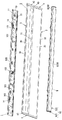
本実施形態の照明器具は、図1〜図5に示すように、光源ユニット6と、光源ユニット6が着脱可能に取り付けられる器具本体1とを備える。また、本実施形態の照明器具は、器具本体1に取り付けられて光源ユニット6から放射される光の配光を制御するための反射板ユニット2を備えることが好ましい。
The lighting fixture of this embodiment is provided with the
本実施形態における光源ユニット6は、特許文献1記載の従来例における光源ユニットと共通の構成を有している。光源ユニット6は、図1、図2及び図5に示すように、光源モジュール60と、取付部材61と、カバー62と、係止金具63と、取付ばね64と、電源ユニット65とを有することが好ましい。
The
光源モジュール60は、長尺の矩形平板状に形成される基板601と、基板601の下面に実装される複数個の固体発光素子(発光ダイオード)600とを有する。複数個の発光ダイオード600は、基板601の下面における短手方向の中央に、長手方向に沿って等間隔且つ2列に並べて実装される(図5参照)。
The
取付部材61は、板金に曲げ加工を施すことにより、長尺且つ矩形板状の底壁部610と、底壁部610の左右方向(短手方向)における両端から上下方向に延出する一対の側壁部611とを有する角樋状に形成されることが好ましい。底壁部610の下面の中央部に、光源モジュール60が取り付けられる。なお、各側壁部611の先端には、外向き且つ円筒形に巻かれた円筒部612がそれぞれ全長に亘って設けられている。
The
カバー62は、カバー本体620と、一対のカバーエンド621とで構成されることが好ましい。カバー本体620は、アクリル樹脂などの透光性を有する材料により、略半円筒形の主部6200と、主部6200の短手方向(前後方向)の両端部より互いに並行するように上向きに突出した一対の突壁部6201とが一体に形成されている。なお、各突壁部6201の先端(上端)には、図5に示すように、内向きに突出する突起部6202がそれぞれ一体に設けられている。また、主部6200の短手方向の両端部には、主部6200と連なるように各突壁部6201の外側まで延出された延出部6203がそれぞれ一体に形成されている。そして、カバー本体620は、各突壁部6201の突起部6202が、取付部材61の各円筒部612に引っ掛かることにより、光源モジュール60の下方を覆うように取付部材61の下面側に取り付けられる(図5参照)。なお、カバー本体620は乳白色の拡散材が混入され、光源モジュール60から放射される光を拡散させて照明空間へ照射するように構成されることが好ましい。
The
カバーエンド621は、カバー本体620と同じ材料で半円板状に形成され、カバー本体620及び取付部材61の長手方向の両端に取り付けられる(図2参照)。
The
電源ユニット65は、交流の電圧・電流を直流の電圧・電流に変換する電力変換回路や入力端子部、複数の出力端子部、信号端子部などが実装されたプリント配線板が金属製のケース650に収納されて構成される(図1参照)。電源ユニット65は、取付部材61の底壁部610の上面に、ねじ止めなどの適宜の方法で取り付けられる。ただし、入力端子部、出力端子部及び信号端子部は、端子台若しくはレセプタクルコネクタで構成されることが好ましい。
The
係止金具63は、取付部材61にねじ止めされる固定片630と、固定片630と一体に形成されて取付部材61の側方(図1においては後方)に突出する係止片631とを有する。係止片631は、取付部材61の外に飛び出した先端部分が下向きに折り曲げられている。
The locking metal fitting 63 includes a fixing
取付ばね64は、コイル部640と、一対の腕641とを有するねじりコイルばねで構成される。取付ばね64は、保持金具15を介して、取付部材61にコイル部640が保持される。また、取付ばね64の一対の腕641のうちの片方の腕641は、保持金具15に引っ掛けられる。そして、これらの係止金具63及び取付ばね64は、図1に示すように、取付部材61の左右方向における両端寄りの位置に、それぞれ1組ずつ設けられる。
The
器具本体1は、図1に示すように、矩形板状のベース板10と、ベース板10の長手方向に沿った両側(前側及び後側)の端縁から垂れ下がる一対の側板11とを有する。そして、器具本体1は、図5に示すように、ベース板10と一対の側板11に囲まれた空間に、光源ユニット6の少なくとも一部(電源ユニット65及び取付部材61)を収めるように構成される。ただし、ベース板10と一対の側板11とは、亜鉛鋼板などの金属板が曲げ加工されて一体に形成されることが好ましい。
As shown in FIG. 1, the
ベース板10には、電源ケーブルを通すための孔100が長手方向(左右方向)におけるほぼ中央に設けられている(図2参照)。また、ベース板10には、長手方向における両端寄りの位置に、吊りボルトを通すための孔101がそれぞれ設けられている。さらに、ベース板10の下面には、電源ケーブルと電気的に接続される端子台102が取り付けられる(図2参照)。また、端子台102には中継ケーブルが電気的に接続される。そして、中継ケーブルが電源ユニット65の入力端子部と電気的に接続されることにより、外部電源(商用の交流電源)から電源ユニット65に交流電力が供給される。
The
側板11の先端(下端)には、図5に示すように、U字形状の支持部12が一体に設けられることが好ましい。また、側板11は、長手方向に沿って階段状に折り曲げられて構成されることが好ましい。
As shown in FIG. 5, it is preferable that a
反射板ユニット2は、一対の反射板3と、一対のエンド板4とで構成される。反射板3は、図1及び図5に示すように、反射部30と、側壁部31と、突壁部32とを有する。また、反射板3は、反射部30の先端(下端)に枠部33を有することが好ましい。反射部30は、一面(下面)を反射面とする長尺の矩形板状に形成される。側壁部31は、長尺の矩形板状であって、反射部30の長手方向(左右方向)に沿った一端縁(上端縁)から立ち上がるように構成される。突壁部32は、長尺の矩形板状であって、側壁部31の長手方向に沿った先端縁(上端縁)から反射部30と対向する向きに突出するように構成される。また、突壁部32の先端部分は、長手方向に沿って、下向き且つ鈎形に折り曲げられている。枠部33は、長手方向(左右方向)から見た形状がL字形であって、反射部30の長手方向に沿った他端縁(下端縁)から外側に突出するように構成される。ただし、反射部30、側壁部31、突壁部32及び枠部33は、亜鉛鋼板などの金属板が曲げ加工されて一体に形成されることが好ましい。また、反射板3は、白色の塗料で塗装されることが好ましい。すなわち、反射部30の反射面(下面)は、白色塗料の塗膜によって反射率の向上が図られることが好ましい。
The
エンド板4は、図4に示すように、台形状の壁部40と、壁部40の2つの斜辺からそれぞれ一対ずつ突出する結合片41と、壁部40の下端縁から外向きに突出する枠部42とを有する。なお、枠部42の周縁部分は上向きに立ち上がるように構成されている。ただし、壁部40、結合片41及び枠部42は、亜鉛鋼板などの金属板によって一体に形成されることが好ましい。
As shown in FIG. 4, the
而して、反射板ユニット2は、エンド板4の結合片41と反射板3の反射部30とがスポット溶接されることにより、矩形の枠状に形成される。そして、反射板ユニット2においては、図1及び図11に示すように、一対の反射板3の側壁部31同士が前後方向に対向するように配置される。
Thus, the reflecting
ここで、器具本体1と反射板ユニット2を組み立てる手順を説明する。まず、作業者は、各反射板3の突壁部32の先端を、長手方向の一端側から一対の支持部12の内側にそれぞれ挿入する。そして、作業者は、反射板ユニット2に対して、器具本体1を長手方向に沿ってスライドさせる。側板11の長手方向の両端には、切り起こし片からなる結合部13がそれぞれ設けられている。一方、反射板3の突壁部32の先端部分には、切欠がそれぞれ設けられている。そして、作業者は、側板11の結合部13を、突壁部32の切欠にかしめることにより、反射板ユニット2(反射板3)に対して器具本体1を抜け止めし且つ固定する(図11参照)。以上のような手順により、器具本体1と反射板ユニット2が組み立てられる。なお、結合部13が切欠にかしめられると、切欠の部分の塗膜が剥がれ、結合部13と突壁部32が電気的に導通する。
Here, the procedure for assembling the
本実施形態における器具本体1は、特許文献1記載の従来例と同様に、光源ユニット6を取り付けるための一対の取付金具14を備えている。一対の取付金具14は、器具本体1のベース板10の下面における長手方向の両端寄りの位置にそれぞれ取り付けられる(図2参照)。
The instrument
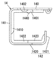
取付金具14は、図6A、図6B及び図7に示すように、平板状のベース部140と、ベース部140の側縁から立ち上がる起立部141と、起立部141の先端部分に設けられて取付ばね64の腕641が引っ掛かる引掛部142とを有する。ただし、ベース部140、起立部141及び引掛部142は、金属板が加工されることで一体に形成されることが好ましい。
As shown in FIGS. 6A, 6B, and 7, the mounting
ベース部140は、左右方向を長手方向とする矩形の平板状に形成される。ベース部140は、長手方向の両端近傍に、それぞれ凹部1400、1401が設けられることが好ましい。凹部1400、1401は、ベース部140の短手方向(前後方向)と平行且つ真っ直ぐに設けられることが好ましい。また、ベース部140の長手方向の中央部分がC字状に切り欠かれることにより、厚み方向に撓み可能な撓み片144が設けられることが好ましい。さらに、撓み片144には、起立部141から離れる方向に、下向き(図6Bにおける上向き)に傾斜して突出する爪1440が形成されることが好ましい。なお、ベース部140の長手方向の両端の隅には、半円形の切り起こし片1402がそれぞれ設けられることが好ましい。
The
起立部141は、台形状に形成されることが好ましい。また、起立部141には、ベース部140の凹部1400、1401と繋がる凹部1410が設けられることが好ましい。凹部1410は、円弧状に設けられることが好ましい。
The
引掛部142は、連結片1420と引掛片1421の2つの部位を有する。連結片1420は、台形状に形成され、幅広な底辺側で起立部141と連結されることが好ましい。また、引掛片1421は、連結片1420の先端に連結され、且つベース部140に近付く向きに曲げ起こされることが好ましい。さらに、引掛片1421は、連結片1420との連結箇所の左右両側に、半円形の切欠1424がそれぞれ設けられることが好ましい。ここで、引掛部142には、起立部141の凹部1410と繋がり、且つ互いに交差する一対の凹部1422、1423が設けられることが好ましい。なお、ベース部140、起立部141及び引掛部142は、金属板が打ち抜き加工及び曲げ加工されることで一体に形成されるが、曲げ加工前の絞り加工によって、各凹部1400、1401、1410、1422、1423が形成されることが好ましい。このように取付金具14を構成する各部140、141、142に凹部1400、…が設けられると、取付金具14の曲げ強度やねじり強度の向上を図ることができる。
The hooking
一方、器具本体1のベース板10は、図8に示すように、ベース部140の両端と嵌合する一対の嵌合部103と、ベース部140を固定する固定部104と、ベース部140を固定部104の固定位置に案内する案内部105とを有する。嵌合部103は、ベース板10の下面との間に隙間を確保するように、ベース板10から切り起こして形成される。すなわち、嵌合部103は、ベース板10との間に確保した前記隙間に、ベース部140の長手方向の端部が挿入されて嵌合するように構成される。
On the other hand, as shown in FIG. 8, the
固定部104は、ベース板10の下面との間に隙間を確保するように、ベース板10が角錐台状に切り起こされて構成されることが好ましい。また、固定部104の底面には、矩形の孔1040が貫通している。すなわち、固定部104は、ベース板10との間に確保した前記隙間に、取付金具14の撓み片144が差し込まれ、且つ撓み片144に設けられた爪1440と孔1040を嵌合させるように構成される。
The fixing
一対の案内部105は、ベース板10の下面側に突出する微少な突起で構成されることが好ましい。そして、これら一対の案内部105は、一対の嵌合部103よりも後方、且つ取付金具14のベース部140に設けられる一対の凹部1400、1401の間隔とほぼ同じ間隔を空けて設けられることが好ましい。
The pair of
次に、図8〜図10を参照して、取付金具14をベース板10に取り付ける手順を説明する。ただし、この取付作業は、器具本体1が反射板ユニット2に組み付けられる前に行われることが好ましい。
Next, with reference to FIGS. 8-10, the procedure which attaches the attachment metal fitting 14 to the
まず、作業者は、ベース板10の下面に沿ってベース部140をスライドさせながら、ベース部140の長手方向の端部を、それぞれ嵌合部103に嵌合させる。このとき、ベース板10の一対の案内部105は、ベース部140の一対の凹部1400、1401内に各別に挿入されることにより、ベース部140を固定部104の固定位置(爪1440と孔1040が嵌合する位置)まで案内することができる。
First, the operator causes the end portions in the longitudinal direction of the
作業者は、ベース部140をスライドさせながら、取付金具14の撓み片144を固定部104とベース板10の間の隙間に挿入する(図9参照)。作業者は、さらにベース部140をスライドさせ、撓み片144の爪1440を固定部104の孔1040に嵌合させる(図10参照)。ここで、一対の案内部105は、取付金具14がスライドされる過程で凹部1400、1401から離脱し、ベース部140を乗り越える。故に、ベース部140が固定位置に在る場合、ベース部140の後端面と一対の案内部105が対向することにより、取付金具14の移動が一対の案内部105によって規制される(図10参照)。上述のようにして、作業者は、取付金具14を器具本体1(のベース板10)に取り付けることができる。なお、器具本体1に取り付けられた取付金具14は、一対の切り起こし片1402をそれぞれ嵌合部103に接触させることで器具本体1との電気的な導通を図るように構成されることが好ましい。
The operator inserts the
従来例においては、取付金具14に相当する係止金具が、取付ねじを用いて、ベース板10に相当する底面部に取り付けられる。一方、本実施形態の照明器具では、取付ねじが用いられること無く、取付金具14がベース板10に取り付けられるので、部品(取付ねじ)が削減されるとともに、ドライバを使ったねじ締めの作業が不要になる。その結果、本実施形態の照明器具は、従来例と比較して、部品点数の削減及び作業性の向上により、更なるコスト削減を図ることができる。
In the conventional example, a locking metal fitting corresponding to the
続いて、本実施形態の照明器具の施工手順を説明する。施工者は、天井裏に先行配線された電源ケーブルを器具本体1の孔100に挿通し、さらに室内側に露出する吊りボルトを孔101に通した後、吊りボルトにナットをねじ込んで器具本体1を吊りボルトに固定する。その後、施工者は、電源ケーブルを端子台102に電気的に接続し、さらに端子台102に電気的に接続されている中継ケーブルを電源ユニット65の入力端子部に電気的に接続する。
Then, the construction procedure of the lighting fixture of this embodiment is demonstrated. The installer inserts the power cable previously wired on the back of the ceiling into the
そして、施工者は、後側の反射板3の側壁部31に設けられた一対の挿通孔310(図1参照)に、光源ユニット6の係止金具63の係止片631の先端を引っ掛けた後、取付ばね64の腕641を、取付金具14の引掛部142に引っ掛ける。最後に、施工者は、係止金具63の係止片631を支点として光源ユニット6を持ち上げるように回転させる。すると、取付ばね64の腕641が引掛部142に引っ掛かったままで元の状態に戻ることにより、取付ばね64のばね力で光源ユニット6が器具本体1に保持される(図5参照)。以上のような手順で照明器具が天井に施工される。
Then, the installer hooks the tip of the
本実施形態の照明器具は上述のように、光源ユニット6と、光源ユニット6が着脱可能に取り付けられる器具本体1とを備える。光源ユニット6は、ねじりコイルばねからなる取付ばね64を有する。器具本体1は、矩形板状のベース板10と、ベース板10に固定される取付金具14とを有する。取付金具14は、平板状のベース部140と、ベース部140の側縁から立ち上がる起立部141と、起立部141の先端部分に設けられて取付ばね64の端部(腕641)が引っ掛かる引掛部142とを有する。ベース板10は、ベース部140の両端と嵌合する一対の嵌合部103と、ベース部140を固定する固定部104と、ベース部140を固定部104の固定位置に案内する案内部105とを有する。
As described above, the lighting fixture of the present embodiment includes the
本実施形態の照明器具は上述のように構成され、取付ねじが用いられること無く、取付金具14がベース板10に取り付けられるので、部品(取付ねじ)が削減されるとともに、ドライバを使ったねじ締めの作業が不要になる。その結果、本実施形態の照明器具は、従来例と比較して、部品点数の削減及び作業性の向上により、更なるコスト削減を図ることができる。
The lighting fixture of the present embodiment is configured as described above, and the mounting
また、本実施形態の照明器具において、ベース部140に凹溝(凹部1400、1401)が設けられることが好ましい。案内部105は、ベース板10の表面から突出して凹溝(凹部1400、1401)に嵌まるように構成されることが好ましい。
Moreover, in the lighting fixture of this embodiment, it is preferable that the
本実施形態の照明器具が上述のように構成されれば、器具本体1のベース板10に対する取付金具14の取付作業の作業性の向上を図ることができる。
If the lighting fixture of this embodiment is comprised as mentioned above, the workability | operativity of the attachment operation | work of the
さらに、本実施形態の照明器具において、案内部105は、ベース部140が前記固定位置に在るとき、ベース部140の移動を規制するように構成されることが好ましい。
Furthermore, in the lighting fixture of this embodiment, it is preferable that the
本実施形態の照明器具が上述のように構成されれば、取付金具14が固定位置から移動することを抑制することができる。 If the lighting fixture of this embodiment is comprised as mentioned above, it can suppress that the attachment metal fitting 14 moves from a fixed position.
また、本実施形態の照明器具において、取付金具14は、ベース部140、起立部141、引掛部142のうちの少なくとも何れか1つに、補強用の凹部1400、1401、1410、1422、1423が形成されることが好ましい。
In addition, in the lighting fixture of the present embodiment, the mounting
本実施形態の照明器具が上述のように構成されれば、取付金具14の強度の向上を図ることができる。 If the lighting fixture of this embodiment is comprised as mentioned above, the improvement of the intensity | strength of the attachment metal fitting 14 can be aimed at.
1 器具本体
6 光源ユニット
10 ベース板
14 取付金具
64 取付ばね
103 嵌合部
104 固定部
105 案内部
140 ベース部
141 起立部
142 引掛部
1400 凹部(凹溝)
1401 凹部(凹溝)
1410 凹部
1422 凹部
1423 凹部
DESCRIPTION OF
1401 Concave part (concave groove)
1410
Claims (4)
前記光源ユニットは、ねじりコイルばねからなる取付ばねを有し、
前記器具本体は、矩形板状のベース板と、前記ベース板に固定される取付金具とを有し、
前記取付金具は、平板状のベース部と、前記ベース部の側縁から立ち上がる起立部と、前記起立部の先端部分に設けられて前記取付ばねの端部が引っ掛かる引掛部とを有し、
前記ベース板は、前記ベース部の両端と嵌合する一対の嵌合部と、前記ベース部を固定する固定部と、前記ベース部を前記固定部の固定位置に案内する案内部とを有することを特徴とする照明器具。 A light source unit, and an instrument body to which the light source unit is detachably attached,
The light source unit has a mounting spring composed of a torsion coil spring,
The instrument body has a rectangular plate-shaped base plate and a mounting bracket fixed to the base plate,
The mounting bracket has a flat base portion, an upright portion that rises from a side edge of the base portion, and a hook portion that is provided at a tip portion of the upright portion and on which an end portion of the mounting spring is hooked.
The base plate includes a pair of fitting portions that are fitted to both ends of the base portion, a fixing portion that fixes the base portion, and a guide portion that guides the base portion to a fixing position of the fixing portion. Lighting equipment characterized by
Priority Applications (1)
| Application Number | Priority Date | Filing Date | Title |
|---|---|---|---|
| JP2014209999A JP6350947B2 (en) | 2014-10-14 | 2014-10-14 | lighting equipment |
Applications Claiming Priority (1)
| Application Number | Priority Date | Filing Date | Title |
|---|---|---|---|
| JP2014209999A JP6350947B2 (en) | 2014-10-14 | 2014-10-14 | lighting equipment |
Publications (2)
| Publication Number | Publication Date |
|---|---|
| JP2016081642A JP2016081642A (en) | 2016-05-16 |
| JP6350947B2 true JP6350947B2 (en) | 2018-07-04 |
Family
ID=55958945
Family Applications (1)
| Application Number | Title | Priority Date | Filing Date |
|---|---|---|---|
| JP2014209999A Active JP6350947B2 (en) | 2014-10-14 | 2014-10-14 | lighting equipment |
Country Status (1)
| Country | Link |
|---|---|
| JP (1) | JP6350947B2 (en) |
Families Citing this family (3)
| Publication number | Priority date | Publication date | Assignee | Title |
|---|---|---|---|---|
| JP6635379B2 (en) * | 2016-05-30 | 2020-01-22 | パナソニックIpマネジメント株式会社 | lighting equipment |
| JP6918127B2 (en) * | 2017-09-26 | 2021-08-11 | 三菱電機株式会社 | Elevator light emitting device |
| JP6970934B2 (en) * | 2018-03-15 | 2021-11-24 | パナソニックIpマネジメント株式会社 | Lighting equipment and lighting equipment |
Family Cites Families (3)
| Publication number | Priority date | Publication date | Assignee | Title |
|---|---|---|---|---|
| JP4132983B2 (en) * | 2002-05-29 | 2008-08-13 | 矢崎総業株式会社 | Clip mounting structure |
| JP5954665B2 (en) * | 2012-10-11 | 2016-07-20 | パナソニックIpマネジメント株式会社 | lighting equipment |
| JP6111494B2 (en) * | 2012-12-05 | 2017-04-12 | パナソニックIpマネジメント株式会社 | lighting equipment |
-
2014
- 2014-10-14 JP JP2014209999A patent/JP6350947B2/en active Active
Also Published As
| Publication number | Publication date |
|---|---|
| JP2016081642A (en) | 2016-05-16 |
Similar Documents
| Publication | Publication Date | Title |
|---|---|---|
| JP6575900B2 (en) | Light source unit and lighting fixture | |
| JP5954665B2 (en) | lighting equipment | |
| JP5954664B2 (en) | lighting equipment | |
| JP6350947B2 (en) | lighting equipment | |
| JP2015141759A (en) | Lighting fixture | |
| JP2022019916A (en) | Lighting fixture | |
| JP6811431B2 (en) | lighting equipment | |
| JP6575897B2 (en) | Light source unit and lighting apparatus | |
| JP5866527B2 (en) | Light source unit and lighting apparatus | |
| JP6887105B2 (en) | lighting equipment | |
| JP6350946B2 (en) | lighting equipment | |
| JP6695060B2 (en) | lighting equipment | |
| JP6531932B2 (en) | lighting equipment | |
| JP6541062B2 (en) | lighting equipment | |
| JP2020024858A (en) | Lighting fixture | |
| JP6218076B2 (en) | lighting equipment | |
| JP2014137932A (en) | Light source device and lighting fixture using the same | |
| JP6528303B2 (en) | Light source unit and lighting apparatus | |
| JP6410172B2 (en) | Power supply device and lighting apparatus | |
| JP2018018608A (en) | Lighting fixture | |
| JP6811809B2 (en) | Lighting device | |
| JP7012246B2 (en) | lighting equipment | |
| JP6854446B2 (en) | lighting equipment | |
| JP6213874B2 (en) | lighting equipment | |
| JP2017224489A (en) | Lighting device |
Legal Events
| Date | Code | Title | Description |
|---|---|---|---|
| RD02 | Notification of acceptance of power of attorney |
Free format text: JAPANESE INTERMEDIATE CODE: A7422 Effective date: 20170209 |
|
| A621 | Written request for application examination |
Free format text: JAPANESE INTERMEDIATE CODE: A621 Effective date: 20170724 |
|
| A977 | Report on retrieval |
Free format text: JAPANESE INTERMEDIATE CODE: A971007 Effective date: 20180418 |
|
| TRDD | Decision of grant or rejection written | ||
| A01 | Written decision to grant a patent or to grant a registration (utility model) |
Free format text: JAPANESE INTERMEDIATE CODE: A01 Effective date: 20180501 |
|
| A61 | First payment of annual fees (during grant procedure) |
Free format text: JAPANESE INTERMEDIATE CODE: A61 Effective date: 20180525 |
|
| R151 | Written notification of patent or utility model registration |
Ref document number: 6350947 Country of ref document: JP Free format text: JAPANESE INTERMEDIATE CODE: R151 |