JP6346309B2 - Fixing structure of vehicle floor mat and fixing structure to member - Google Patents

Fixing structure of vehicle floor mat and fixing structure to member Download PDF

Info

Publication number
JP6346309B2
JP6346309B2 JP2016566096A JP2016566096A JP6346309B2 JP 6346309 B2 JP6346309 B2 JP 6346309B2 JP 2016566096 A JP2016566096 A JP 2016566096A JP 2016566096 A JP2016566096 A JP 2016566096A JP 6346309 B2 JP6346309 B2 JP 6346309B2
Authority
JP
Japan
Prior art keywords
mat
floor
fixing member
fixing
locking
Prior art date
Legal status (The legal status is an assumption and is not a legal conclusion. Google has not performed a legal analysis and makes no representation as to the accuracy of the status listed.)
Active
Application number
JP2016566096A
Other languages
Japanese (ja)
Other versions
JPWO2016104143A1 (en
Inventor
後藤 剛
剛 後藤
岩下 和樹
和樹 岩下
龍 服部
龍 服部
Current Assignee (The listed assignees may be inaccurate. Google has not performed a legal analysis and makes no representation or warranty as to the accuracy of the list.)
Piolax Inc
Honda Access Corp
Original Assignee
Piolax Inc
Honda Access Corp
Priority date (The priority date is an assumption and is not a legal conclusion. Google has not performed a legal analysis and makes no representation as to the accuracy of the date listed.)
Filing date
Publication date
Application filed by Piolax Inc, Honda Access Corp filed Critical Piolax Inc
Publication of JPWO2016104143A1 publication Critical patent/JPWO2016104143A1/en
Application granted granted Critical
Publication of JP6346309B2 publication Critical patent/JP6346309B2/en
Active legal-status Critical Current
Anticipated expiration legal-status Critical

Links

Images
Classifications

    • BPERFORMING OPERATIONS; TRANSPORTING
    • B60VEHICLES IN GENERAL
    • B60NSEATS SPECIALLY ADAPTED FOR VEHICLES; VEHICLE PASSENGER ACCOMMODATION NOT OTHERWISE PROVIDED FOR
    • B60N3/00Arrangements or adaptations of other passenger fittings, not otherwise provided for
    • B60N3/04Arrangements or adaptations of other passenger fittings, not otherwise provided for of floor mats or carpets

Landscapes

  • Engineering & Computer Science (AREA)
  • Transportation (AREA)
  • Mechanical Engineering (AREA)
  • Passenger Equipment (AREA)

Description

本発明は、車両にフロアマットを固定する車両用フロアマットの固定構造及び部材への固定構造に関する。   The present invention relates to a vehicle floor mat fixing structure and a member fixing structure for fixing a floor mat to a vehicle.

従来、この種のものとして、マット本体と、このマット本体を車両に固定する固定構造とを備えた車両用フロアマットにおいて、前記固定構造は、前記車両に固定した第一固定部材(本発明のフロア固定部材又は固定部材に相当)と、前記マット本体に固定した第二固定部材(本発明の第一マット固定部材又は第一部材に相当)とを備え、前記第一固定部材は、上下方向を軸とした回転ノブを備え、前記第二固定部材に前記回転ノブを挿入する挿入受け部を設け、この挿入受け部に挿入した前記回転ノブの回転により前記挿入受け部に前記回転ノブが係止し、前記第二固定部材は前記回転ノブの回転を阻止する回転阻止部材を備える車両用フロアマット(例えば特許文献1)が提案されている。   Conventionally, in this type of vehicle floor mat including a mat main body and a fixing structure for fixing the mat main body to a vehicle, the fixing structure is a first fixing member fixed to the vehicle (of the present invention). A floor fixing member or a fixing member) and a second fixing member (corresponding to the first mat fixing member or the first member of the present invention) fixed to the mat body. And a rotation receiving knob for inserting the rotation knob into the second fixing member, and the rotation knob is engaged with the insertion receiving portion by rotation of the rotation knob inserted into the insertion receiving portion. A vehicle floor mat (for example, Patent Document 1) is proposed in which the second fixing member includes a rotation blocking member that blocks rotation of the rotary knob.

また、防水性に優れたフロアマットとして、熱可塑性樹脂、熱可塑性エラストマー、熱硬化性樹脂、或いは天然又は合成ゴムからなる車両用フロアマット(例えば特許文献2)がある。   Moreover, as a floor mat excellent in waterproofness, there is a vehicle floor mat (for example, Patent Document 2) made of thermoplastic resin, thermoplastic elastomer, thermosetting resin, or natural or synthetic rubber.

上記特許文献1の車両用フロアマットでは、マット本体の車両に対する固定機構を回転ノブとレバーにより二段階で固定することで強固な固定が可能となる。   The vehicle floor mat disclosed in Patent Document 1 can be firmly fixed by fixing the fixing mechanism of the mat body to the vehicle in two stages with a rotary knob and a lever.

ところで、特許文献1のような車両用フロアマットにおいて、マット本体の汚れを防止するため、該マット本体に特許文献2のようなゴム製などのフロアマットを重ねる使用者が多数存在している。   By the way, in the vehicle floor mat as disclosed in Patent Document 1, in order to prevent the mat body from being soiled, there are many users who overlap the mat body with a rubber floor mat as disclosed in Patent Document 2.

しかし、上記特許文献1の固定構造では、フロアマットの上にさらにフロアマットを重ねた場合、その上のフロアマットを固定する構造がないため、上のフロアマットがずれるなどして不便であった。   However, in the fixing structure of Patent Document 1, when a floor mat is further stacked on the floor mat, there is no structure for fixing the floor mat on the floor mat, which is inconvenient because the upper floor mat is shifted. .

これに対して、車両の床面に2枚のマットを敷設するものとして、以下の先行技術が開示されている。   On the other hand, the following prior art is disclosed as laying two mats on the floor of a vehicle.

例えば、フロアマットに穿設された貫通穴に、樹脂製アイレットを固定し、旋回腕の一端部下面に突設した割り軸を、前記樹脂製アイレットに弾性を利用して嵌合係着するとともに、前記旋回腕の他端部上面に突出した擬宝珠形軸を、オプションマットの貫通穴に固定した樹脂製アイレットに係止するもの(例えば特許文献3)や、純正マットの下方に挿入される板状の基部と、この基部の端部に上方に突設され、純正マットの周縁部に当接する係合部とを備え、この係合部の上部に、汎用のマットを着脱自在に上下方向から挟んで保持するクリップ部を設けたもの(例えば特許文献4)や、第2フロアマットと、前記第2フロアマットを前記自動車用フロアカーペットに固定するフロアマット固定具とを備え、前記第2フロアマットは、周囲に壁面を有する容器状であり、底面部から前方又は後方に延設した延設部に設けた貫通孔を備え、また、フロアマット固定具は、前記自動車用フロアカーペットに固定する固定部を備えた基部と、前記基部の上方に第1フロアマット挿入空間を形成するように連設部を介して配置された第1フロアマット挟持部とを備えており、前記第1フロアマット挟持部の上面には、フックを備えるもの(例えば特許文献5)などが提案されている。   For example, a resin eyelet is fixed to a through-hole drilled in a floor mat, and a split shaft projecting from the lower surface of one end of a swivel arm is fitted and engaged with the resin eyelet using elasticity. , A quasi-jewel-shaped shaft projecting from the upper surface of the other end of the swivel arm, which is engaged with a resin eyelet fixed to the through hole of the option mat (for example, Patent Document 3), or a plate inserted below the genuine mat And a mating base that protrudes upward at the end of the base and abuts against the peripheral edge of the genuine mat. A general-purpose mat is detachably attached to the top of the mating part from above and below. A second floor mat, and a floor mat fixture for fixing the second floor mat to the automobile floor carpet. Matt And a through-hole provided in an extending portion extending forward or backward from the bottom surface portion, and the floor mat fixture includes a fixing portion for fixing to the automobile floor carpet. And a first floor mat sandwiching portion disposed via a continuous portion so as to form a first floor mat insertion space above the base, and an upper surface of the first floor mat sandwiching portion Has been proposed that includes a hook (for example, Patent Document 5).

特許第5478592号公報Japanese Patent No. 5478592 特開2011−79446号公報JP 2011-79446 A 実用新案登録第2583948号公報Utility Model Registration No. 2583948 実用新案登録第3148696号公報Utility Model Registration No. 3148696 特開2011−240861号公報JP2011-240861A

上記特許文献3では、オプションマットの貫通穴に固定した樹脂製アイレットに係止するものであるから、オプションマットの上下方向の抜け止めがなされておらず、上記特許文献4では、上のマットをクリップ部に挟む構造であるから、クリップ部からマットが外れる虞があり、上記特許文献5では、フック部に第2フロアマットを係止する構造であるから、第2フロアマットの上下方向の抜け止めを防止できない。   In the above Patent Document 3, the option mat is locked to the resin eyelet fixed in the through hole of the option mat, so that the option mat is not secured in the vertical direction. Since the structure is sandwiched between the clip portions, the mat may come off from the clip portions. In Patent Document 5, the second floor mat is locked to the hook portion. Stop cannot be prevented.

また、上記特許文献3〜5では、上のマットを用いない場合でも、特許文献3では上部に擬宝珠形軸が突出し、特許文献4ではクリップ部が上部に突出し、特許文献5ではフックが上部に突出するから突出部分が邪魔になる。尚、特許文献4のクリップ部は一応取り外すことができるが、ある程度以上の力でクリップ部を上方に引き上げる必要があるため、通常の使用においては、クリップ部を簡便に取り外すことはできなかった。   Further, in Patent Documents 3 to 5, even if the upper mat is not used, in Patent Document 3, the pseudo jewel-shaped shaft protrudes upward, in Patent Document 4, the clip portion protrudes upward, and in Patent Document 5, the hook extends upward. Since it protrudes, the protruding part gets in the way. In addition, although the clip part of patent document 4 can be removed temporarily, since it is necessary to pull up a clip part upwards with a certain amount of force or more, in normal use, the clip part was not able to be removed simply.

ところで、特許文献1の固定構造では、前記第二固定部材に前記回転ノブを挿入する挿入受け部を設け、この挿入受け部に挿入した前記回転ノブの回転により前記挿入受け部に前記回転ノブが係止するため、マット本体を確実に固定することができるが、第二固定部材の内部に砂や土などが侵入する虞がある。   By the way, in the fixing structure of Patent Document 1, an insertion receiving portion for inserting the rotating knob is provided in the second fixing member, and the rotating knob is inserted into the insertion receiving portion by the rotation of the rotating knob inserted into the insertion receiving portion. Since the mat body can be securely fixed because of the locking, there is a possibility that sand, soil, or the like may enter the inside of the second fixing member.

そこで、本発明は上記した問題点に鑑み、車両の床面に第一マット本体を固定することができ、第一マット固定部材の内部への砂や土等の侵入を防止する ことができる車両用フロアマットの固定構造を提供することを目的とする。   Therefore, in view of the above-described problems, the present invention can fix the first mat body to the floor surface of the vehicle, and can prevent intrusion of sand, soil, or the like into the first mat fixing member. An object of the present invention is to provide a floor mat fixing structure.

また、本発明は上記した問題点に鑑み、第一固定部材の内部への砂や土等の侵入を防止することができ、また、回転ノブによる係止状態を確認することができる部材への固定構造を提供することを目的とする。   In addition, in view of the above-described problems, the present invention can prevent sand or earth from entering the inside of the first fixing member, and can be used to check the locking state of the rotary knob. The object is to provide a fixed structure.

上記目的を達成するために、請求項1に係る発明は、第一マット本体を車両の床面に設けられたフロア固定部材に固定する車両用フロアマットの固定構造において、前記車両の床面に設けた前記フロア固定部材と、前記第一マット本体に固定した第一マット固定部材と、前記第一マット固定部材に着脱自在に固定する中間部材とを備え、前記フロア固定部材は上下方向を軸としたフロア回転ノブを備え、前記第一マット固定部材には前記フロア回転ノブを挿入する第一挿入受け部を設け、前記第一マット固定部材の前記第一挿入受け部に挿入した前記フロア回転ノブの回転により前記第一挿入受け部に該フロア回転ノブが係止して前記車両に前記第一マット本体が固定され、前記第一マット固定部材の上部には前記中間部材と係止可能な第一係止部を設け、前記中間部材の下部には前記第一係止部と係止可能な中間係止受け部を設け、前記中間係止受け部と前記第一係止部が係止して前記第一マット固定部材に前記中間部材が固定されることを特徴とする。また、前記中間部材は、前記フロア回転ノブと略同軸となる軸を中心とした回転操作を行うことにより、前記中間係止受け部と前記第一係止部とを係止できることを特徴とする。 In order to achieve the above object, the invention according to claim 1 is directed to a vehicle floor mat fixing structure for fixing a first mat body to a floor fixing member provided on a vehicle floor surface. The floor fixing member is provided, a first mat fixing member fixed to the first mat body, and an intermediate member that is detachably fixed to the first mat fixing member. The first mat fixing member is provided with a first insertion receiving portion for inserting the floor rotation knob, and the floor rotation knob is inserted into the first insertion receiving portion of the first mat fixing member. The floor rotation knob is locked to the first insertion receiving portion by rotation of the knob to fix the first mat body to the vehicle, and the intermediate member can be locked to the upper portion of the first mat fixing member. first An intermediate latch receiving portion that can be engaged with the first engaging portion, and the intermediate engaging receiving portion and the first engaging portion are engaged with each other. The intermediate member is fixed to the first mat fixing member. Further, the intermediate member is capable of locking the intermediate locking receiving portion and the first locking portion by performing a rotation operation around an axis that is substantially coaxial with the floor rotation knob. .

請求項1の構成によれば、固定構造の上部に中間部材を配置することにより、固定構造内部の目隠しとすることができる。また、固定構造の内部への砂,土や塵埃等の侵入を防止することができる。また、フロア回転ノブを第一挿入受け部に係止する操作と、中間部材を取り付ける操作とを同様の回転操作としたことにより、第一マット固定部材と中間部材との係止操作を直感的で判り易いものとすることができる。 According to the structure of Claim 1, it can be set as the blindfold inside a fixed structure by arrange | positioning an intermediate member on the upper part of a fixed structure. In addition, it is possible to prevent sand, earth, dust, and the like from entering the fixed structure. In addition, the operation of locking the floor rotation knob to the first insertion receiving portion and the operation of attaching the intermediate member are the same rotation operation, so that the operation of locking the first mat fixing member and the intermediate member is intuitive. It can be made easy to understand.

請求項に係る発明は、第一マット本体を車両の床面に設けられたフロア固定部材に固定する車両用フロアマットの固定構造において、前記車両の床面に設けた前記フロア固定部材と、前記第一マット本体に固定した第一マット固定部材と、前記第一マット固定部材に着脱自在に固定する中間部材とを備え、前記フロア固定部材は上下方向を軸としたフロア回転ノブを備え、前記第一マット固定部材には前記フロア回転ノブを挿入する第一挿入受け部を設け、前記第一マット固定部材の前記第一挿入受け部に挿入した前記フロア回転ノブの回転により前記第一挿入受け部に該フロア回転ノブが係止して前記車両に前記第一マット本体が固定され、前記第一マット固定部材の上部には前記中間部材と係止可能な第一係止部を設け、前記中間部材の下部には前記第一係止部と係止可能な中間係止受け部を設け、前記中間係止受け部と前記第一係止部が係止して前記第一マット固定部材に前記中間部材が固定され、前記第一マット本体に重ねる第二マット本体と、前記第二マット本体に固定した第二マット固定部材とを備え、前記中間部材の上部には前記フロア回転ノブと略同軸となる中間回転ノブを設け、前記第二マット固定部材には前記中間回転ノブを挿入する第二挿入受け部を設け、前記第二マット固定部材の前記第二挿入受け部に挿入した前記中間回転ノブの回転により前記第二挿入受け部に該中間回転ノブが係止して前記車両に前記第二マット本体が固定されることを特徴とする。 The invention according to claim 2 is the vehicle floor mat fixing structure for fixing the first mat body to the floor fixing member provided on the floor of the vehicle, and the floor fixing member provided on the floor of the vehicle; A first mat fixing member fixed to the first mat main body, and an intermediate member fixed to the first mat fixing member in a detachable manner, the floor fixing member includes a floor rotation knob about the vertical direction; The first mat fixing member is provided with a first insertion receiving portion for inserting the floor rotation knob, and the first insertion is performed by rotation of the floor rotation knob inserted in the first insertion receiving portion of the first mat fixing member. The floor rotation knob is locked to a receiving portion, and the first mat body is fixed to the vehicle. A first locking portion that can be locked to the intermediate member is provided on an upper portion of the first mat fixing member. Intermediate member An intermediate locking receiving portion that can be locked with the first locking portion is provided at a lower portion, and the intermediate locking receiving portion and the first locking portion are locked to the intermediate member to the first mat fixing member. A second mat body that is fixed to the first mat body, and a second mat fixing member that is fixed to the second mat body, and the upper portion of the intermediate member is substantially coaxial with the floor rotation knob. An intermediate rotation knob is provided, the second mat fixing member is provided with a second insertion receiving portion for inserting the intermediate rotation knob, and the intermediate rotation knob inserted into the second insertion receiving portion of the second mat fixing member is provided. The intermediate rotation knob is locked to the second insertion receiving portion by rotation, and the second mat body is fixed to the vehicle.

請求項の構成によれば、固定構造の上部に中間部材を配置することにより、固定構造内部の目隠しとすることができる。また、固定構造の内部への砂,土や塵埃等の侵入を防止することができる。また、第一マット固定部材の上部に中間部材を取り付け、これに第二マット本体を取り付ける構成としたので、固定構造の内部への砂,土や塵埃等の侵入を防止することができるとともに、前記中間部材を介して第二マット本体を車両に固定することができる。 According to the structure of Claim 2 , it can be set as the blindfold inside a fixed structure by arrange | positioning an intermediate member in the upper part of a fixed structure. In addition, it is possible to prevent sand, earth, dust, and the like from entering the fixed structure. In addition, since the intermediate member is attached to the upper portion of the first mat fixing member and the second mat main body is attached to the intermediate member, it is possible to prevent intrusion of sand, earth, dust, etc. into the fixing structure, The second mat body can be fixed to the vehicle via the intermediate member.

また、中間回転ノブはフロア回転ノブと略同軸としたため、同軸状に固定構造を配置することができ、コンパクトな設計とすることができる。   Further, since the intermediate rotation knob is substantially coaxial with the floor rotation knob, the fixing structure can be arranged coaxially, and a compact design can be achieved.

さらに、フロア固定部材、第一マット固定部材、中間部材、第二マット固定部材をそれぞれ連結して固定する構造としたため、強固な固定構造とすることができる。   Furthermore, since the floor fixing member, the first mat fixing member, the intermediate member, and the second mat fixing member are connected and fixed, respectively, a strong fixing structure can be obtained.

請求項に係る発明は、第一マット本体を車両の床面に設けられたフロア固定部材に固定する車両用フロアマットの固定構造において、前記車両の床面に設けた前記フロア固定部材と、前記第一マット本体に固定した第一マット固定部材と、前記第一マット固定部材に着脱自在に固定する中間部材とを備え、前記フロア固定部材は上下方向を軸としたフロア回転ノブを備え、前記第一マット固定部材には前記フロア回転ノブを挿入する第一挿入受け部を設け、前記第一マット固定部材の前記第一挿入受け部に挿入した前記フロア回転ノブの回転により前記第一挿入受け部に該フロア回転ノブが係止して前記車両に前記第一マット本体が固定され、前記第一マット固定部材の上部には前記中間部材と係止可能な第一係止部を設け、前記中間部材の下部には前記第一係止部と係止可能な中間係止受け部を設け、前記中間係止受け部と前記第一係止部が係止して前記第一マット固定部材に前記中間部材が固定され、前記第一マット固定部材の前記第一係止部は、前記第一マット固定部材の上部に設けた外向き鍔部であり、前記外向き鍔部を部分的に切り欠いて挿通部を設け、前記中間部材の前記中間係止受け部は、前記中間部材の下部に設けられ前記挿通部に上方から挿通可能で、前記中間部材の回転により前記外向き鍔部の下面に係止することを特徴とする。 The invention according to claim 3 is the vehicle floor mat fixing structure for fixing the first mat body to the floor fixing member provided on the floor surface of the vehicle, and the floor fixing member provided on the floor surface of the vehicle; A first mat fixing member fixed to the first mat main body, and an intermediate member fixed to the first mat fixing member in a detachable manner, the floor fixing member includes a floor rotation knob about the vertical direction; The first mat fixing member is provided with a first insertion receiving portion for inserting the floor rotation knob, and the first insertion is performed by rotation of the floor rotation knob inserted in the first insertion receiving portion of the first mat fixing member. The floor rotation knob is locked to a receiving portion, and the first mat body is fixed to the vehicle. A first locking portion that can be locked to the intermediate member is provided on an upper portion of the first mat fixing member. Intermediate member An intermediate locking receiving portion that can be locked with the first locking portion is provided at a lower portion, and the intermediate locking receiving portion and the first locking portion are locked to the intermediate member to the first mat fixing member. Is fixed, and the first locking portion of the first mat fixing member is an outward flange provided on an upper portion of the first mat fixing member, and is partially inserted through the outward flange. The intermediate locking receiving portion of the intermediate member is provided at the lower portion of the intermediate member and can be inserted through the insertion portion from above, and is locked to the lower surface of the outward flange portion by the rotation of the intermediate member. It is characterized by doing.

請求項の構成によれば、固定構造の上部に中間部材を配置することにより、固定構造内部の目隠しとすることができる。また、固定構造の内部への砂,土や塵埃等の侵入を防止することができる。また、回転操作により中間部材を第一マット固定部材と固定する構造としたため、上方から荷重が掛かっても係止が容易に解除されることが無い。 According to the structure of Claim 3 , it can be set as the blindfold inside a fixed structure by arrange | positioning an intermediate member in the upper part of a fixed structure. In addition, it is possible to prevent sand, earth, dust, and the like from entering the fixed structure. Further, since the intermediate member is fixed to the first mat fixing member by the rotation operation , the locking is not easily released even when a load is applied from above.

請求項に係る発明は、前記第一挿入受け部と前記第二挿入受け部とが略同一であり、前記フロア回転ノブが前記第二マット固定部材の前記第二挿入受け部に係止可能なことを特徴とする。 In the invention according to claim 4 , the first insertion receiving portion and the second insertion receiving portion are substantially the same, and the floor rotation knob can be locked to the second insertion receiving portion of the second mat fixing member. It is characterized by that.

請求項の構成によれば、第一挿入受け部と第二挿入受け部が略同一構造であり、且つ、前記フロア回転ノブが前記第二マット固定部材の第二挿入受け部に係止可能なため、従来から行われているフロア固定部材と第一マット本体の固定はもちろん、フロア固定部材と第二マット固定部材による第二マット本体のみの車両への固定を行うことができる。 According to the configuration of the fourth aspect , the first insertion receiving portion and the second insertion receiving portion have substantially the same structure, and the floor rotation knob can be locked to the second insertion receiving portion of the second mat fixing member. Therefore, the floor fixing member and the first mat main body, which have been conventionally used, can be fixed, and only the second mat main body can be fixed to the vehicle by the floor fixing member and the second mat fixing member.

請求項係る発明は、前記中間部材の下部中央には、前記フロア回転ノブと略同軸であると共に該フロア回転ノブと係止可能なノブ係止受け部を設け、前記フロア回転ノブと前記ノブ係止受け部とが係止した状態で前記中間部材を回転操作することにより、前記フロア回転ノブが前記第一挿入受け部に係止して前記車両に前記第一マット本体が固定されると共に、前記第一係止部に前記中間係止受け部が係止して前記中間部材が前記第一マット固定部材に固定されることを特徴とする。 According to a fifth aspect of the present invention, a knob engagement receiving portion that is substantially coaxial with the floor rotation knob and engageable with the floor rotation knob is provided at the lower center of the intermediate member, and the floor rotation knob and the knob are provided. By rotating the intermediate member in a state in which the latch receiving portion is locked, the floor rotation knob is locked to the first insertion receiving portion, and the first mat body is fixed to the vehicle. The intermediate locking receiving portion is locked to the first locking portion, and the intermediate member is fixed to the first mat fixing member.

請求項の構成によれば、中間部材を第一マット固定部材に固定する回転操作により、フロア回転ノブを連動して回転することができるため、第一マット本体とフロア固定部材との固定を同時に行うことができる。 According to the configuration of the fifth aspect , the rotation operation for fixing the intermediate member to the first mat fixing member can be rotated in conjunction with the floor rotation knob, so that the first mat body and the floor fixing member can be fixed. Can be done simultaneously.

また、通常、カバーを設けた場合、第一マット本体とフロア固定部材との係止状態を確認することができないが、上記構造としたことにより、中間部材の第一マット固定部材への固定と、第一マット本体のフロア固定部材への固定とが同時に行われ、確実に第一マット本体を床面に固定されていることを確認できる。   Also, normally, when a cover is provided, it is not possible to confirm the locking state between the first mat body and the floor fixing member, but by adopting the above structure, the intermediate member can be fixed to the first mat fixing member. The first mat body is fixed to the floor fixing member at the same time, and it can be confirmed that the first mat body is securely fixed to the floor surface.

請求項に係る発明は、前記第一マット固定部材に前記中間部材を軸方向上方から被せることにより、前記フロア回転ノブに前記ノブ係止受け部が係止され、前記フロア回転ノブが前記第一挿入受け部との係止解除位置にあるときに、前記中間部材を上方から被せることが可能なことを特徴とする。 According to a sixth aspect of the present invention, the intermediate member is covered with the first mat fixing member from above in the axial direction, whereby the knob locking receiving portion is locked to the floor rotation knob, and the floor rotation knob is The intermediate member can be covered from above when in the unlocking position with respect to the one insertion receiving portion.

請求項の構成によれば、フロア回転ノブが第一マット固定部材に係止した位置にあるときに中間部材が第一マット固定部材に係止してしまった場合、中間部材の回転操作によりフロア回転ノブと第一マット固定部材との係止状態が解除されてしまう問題がある。これに対して、フロア回転ノブが係止解除位置にあるときに中間部材が係止する構造のため、上記問題が発生しない。 According to the configuration of claim 6 , when the intermediate member is locked to the first mat fixing member when the floor rotation knob is at the position locked to the first mat fixing member, There is a problem that the locked state between the floor rotation knob and the first mat fixing member is released. On the other hand, since the intermediate member is locked when the floor rotation knob is in the unlocking position, the above problem does not occur.

請求項に係る発明は、前記ノブ係止受け部は、前記係止解除位置の前記フロア回転ノブに係止可能な係止用突起部と、前記係止解除位置以外の前記フロア回転ノブに当接し、前記第一係止部と前記中間係止受け部との係止を規制する規制部とを備えることを特徴とする。 According to a seventh aspect of the present invention, the knob lock receiving portion includes a locking projection that can be locked to the floor rotation knob at the lock release position, and the floor rotation knob other than the lock release position. It comprises a restricting portion that abuts and restricts the locking between the first locking portion and the intermediate locking receiving portion.

請求項の構成によれば、規制部により、フロア回転ノブが係止解除位置にあるときにのみ中間部材を軸上方から被せることが可能になる。さらに、フロア回転ノブが係止解除位置以外のときは、規制部がフロア回転ノブに当接することにより前記第一係止部と前記中間係止受け部の係止が規制される。 According to the configuration of the seventh aspect , the restricting portion allows the intermediate member to be covered from above the shaft only when the floor rotation knob is in the unlocking position. Further, when the floor rotation knob is at a position other than the unlocking position, the locking of the first locking portion and the intermediate locking receiving portion is restricted by the restriction portion coming into contact with the floor rotation knob.

請求項に係る発明は、前記係止用突起部は縦壁、もしくは複数のピンにより前記フロア回転ノブの外周部に係止することを特徴とする。 The invention according to claim 8 is characterized in that the locking projection is locked to the outer peripheral portion of the floor rotation knob by a vertical wall or a plurality of pins.

請求項の構成によれば、係止用突起部の形状変更が容易で、安価な構成とすることができる。 According to the configuration of the eighth aspect , the shape of the locking projection can be easily changed, and the configuration can be made inexpensive.

さらに、フロア固定部材、第一マット固定部材、中間部材、第二マット固定部材をそれぞれ連結して固定する構造としたため、強固な固定構造とすることができる。   Furthermore, since the floor fixing member, the first mat fixing member, the intermediate member, and the second mat fixing member are connected and fixed, respectively, a strong fixing structure can be obtained.

請求項に係る発明は、前記中間係止受け部と前記第一係止部とが係止位置にあることを確認可能な係止位置確認構造を備えることを特徴とする。 The invention according to claim 9 is provided with a locking position confirmation structure capable of confirming that the intermediate locking receiving portion and the first locking portion are in the locking position.

請求項の構成によれば、第一マット固定部材は中間部材の下方に位置し、回転操作により係止されるため、正規の回転位置で係止しているか否か確認しづらいが、係止位置確認構造を設けたため、中間部材が第一マット固定部材に係止された状態でも、確実に係止状態であることを確認することができる。 According to the configuration of the ninth aspect , since the first mat fixing member is located below the intermediate member and is locked by the rotation operation, it is difficult to confirm whether or not the first mat fixing member is locked at the regular rotation position. Since the stop position confirmation structure is provided, it is possible to confirm that the intermediate member is securely locked even when the intermediate member is locked to the first mat fixing member.

請求項10に係る発明は、クリック感により前記係止位置を確認する前記係止位置確認構造は、前記第一マット固定部材と前記中間部材の一方にクリック凹部を設けると共に、他方にクリック凸部を設け、前記係止位置で前記クリック凹部と前記クリック凸部が係合することを特徴とする。 The invention according to claim 10 is characterized in that the locking position confirmation structure for confirming the locking position by a click feeling is provided with a click concave portion in one of the first mat fixing member and the intermediate member and a click convex portion in the other. And the click concave portion and the click convex portion are engaged at the locking position.

請求項10の構成によれば、回転操作により第一マット固定部材と中間部材とが係止状態となるときに、クリック感が発生するため係止位置を確実に認識することができる。 According to the configuration of the tenth aspect , when the first mat fixing member and the intermediate member are brought into the locked state by the rotation operation, a click feeling is generated, so that the locked position can be surely recognized.

請求項11に係る発明は、視認により前記係止位置を確認する前記係止位置確認構造は、前記第一マット固定部材との回転位置を確認できる開口部を前記中間部材に設け、前記第一マット固定部材には、前記中間部材と係止状態で前記開口部から視認不可能な位置に目印を設けたことを特徴とする。 According to an eleventh aspect of the present invention, in the locking position confirmation structure for confirming the locking position by visual recognition, an opening for confirming a rotation position with the first mat fixing member is provided in the intermediate member. The mat fixing member is characterized in that a mark is provided at a position where the mat fixing member is not visible from the opening in a locked state with the intermediate member.

請求項11の構成によれば、開口部から目印が視認される場合には正規の係止位置でないことが確認できる。 According to the structure of Claim 11 , when a mark is visually recognized from an opening part, it can confirm that it is not a regular latching position.

請求項12に係る発明は、視認により前記係止位置を確認する前記係止位置確認構造は、前記第一マット固定部材との回転位置を確認できる開口部を前記中間部材に設け、前記第一マット固定部材には、前記中間部材と係止状態で前記開口部から視認可能な位置に目印を設けたことを特徴とする。 According to a twelfth aspect of the present invention, in the locking position confirmation structure for confirming the locking position by visual recognition, an opening for confirming a rotational position with respect to the first mat fixing member is provided in the intermediate member. The mat fixing member is characterized in that a mark is provided at a position that is visible from the opening in a locked state with the intermediate member.

請求項12の構成によれば、開口部から目印がずれて視認された場合には正規の係合位置でないことが確認できる。 According to the configuration of the twelfth aspect , when the mark is visually recognized with a deviation from the opening, it can be confirmed that the position is not a normal engagement position.

請求項13に係る発明は、視認により前記係止位置を確認する前記係止位置確認構造は、前記第一マット固定部材との回転位置を確認できる開口部を前記中間部材に設け、前記第一マット固定部材は、係止状態で前記開口部から視認可能な位置の色と他の部位の色とが異なることを特徴とする。 According to a thirteenth aspect of the present invention, in the locking position confirmation structure for confirming the locking position by visual recognition, an opening is provided in the intermediate member so that the rotation position with respect to the first mat fixing member can be confirmed. The mat fixing member is characterized in that the color of the position visible from the opening in the locked state is different from the color of other parts.

請求項13の構成によれば、開口部に現われる色を確認することにより、正規の係止位置であるか否かを判断することができる。 According to the configuration of the thirteenth aspect , it is possible to determine whether or not the position is a normal locking position by confirming the color appearing in the opening.

請求項14に係る発明は、第一部材を部材に設けられた固定部材に固定する固定構造において、前記第一部材に固定した第一固定部材と、前記第一固定部材に着脱自在に固定する中間部材とを備え、前記固定部材は軸状の回転ノブを備え、前記第一固定部材には前記回転ノブを挿入する第一挿入受け部を設け、前記第一固定部材の前記第一挿入受け部に挿入した前記回転ノブの回転により前記第一挿入受け部に該回転ノブが係止して前記部材に前記第一固定部材が固定され、前記第一固定部材には前記中間部材と係止可能な第一係止部を設け、前記中間部材には前記第一係止部と係止可能な中間係止受け部を設け、前記中間部材の回転操作を行うことにより、前記中間係止受け部と前記第一係止部が係止して前記第一固定部材に前記中間部材が固定され、前記中間係止受け部と前記第一係止部とが係止位置にあることを確認可能な係止位置確認構造を備えることを特徴とする。 According to a fourteenth aspect of the present invention, in the fixing structure for fixing the first member to the fixing member provided on the member, the first fixing member fixed to the first member and the first fixing member are detachably fixed. An intermediate member, the fixing member includes an axial rotation knob, the first fixing member is provided with a first insertion receiving portion into which the rotation knob is inserted, and the first insertion receiver of the first fixing member is provided. When the rotary knob inserted into the part is rotated, the rotary knob is locked to the first insertion receiving part, and the first fixing member is fixed to the member. The first fixing member is locked to the intermediate member. The intermediate member is provided with an intermediate latch receiving portion that can be latched with the first latching portion, and the intermediate member is rotated, whereby the intermediate latch receiver The intermediate member is fixed to the first fixing member by locking the portion and the first locking portion. Fixed, characterized in that said intermediate latch receiving portion and the first locking portion comprises a verifiable locking orientation structure that in a locked position.

請求項14の構成によれば、第一固定部材は中間部材の下方に位置し、回転操作により係止されるため、正規の回転位置で係止しているか否か確認しづらいが、係止位置確認構造を設けたため、中間部材が第一固定部材に係止された状態でも、確実に係止状態であることを確認することができる。 According to the configuration of the fourteenth aspect , the first fixing member is located below the intermediate member and is locked by the rotation operation. Therefore, it is difficult to confirm whether or not the first fixing member is locked at the regular rotation position. Since the position confirmation structure is provided, even when the intermediate member is locked to the first fixing member, it can be surely confirmed that the intermediate member is in the locked state.

請求項15に係る発明は、クリック感により前記係止位置を確認する前記係止位置確認構造は、前記第一固定部材と前記中間部材の一方にクリック凹部を設けると共に、他方にクリック凸部を設け、前記係止位置で前記クリック凹部と前記クリック凸部が係合することを特徴とする。 According to a fifteenth aspect of the present invention, in the locking position confirmation structure for confirming the locking position by a click feeling, a click concave portion is provided on one of the first fixing member and the intermediate member, and a click convex portion is provided on the other. And the click concave portion and the click convex portion are engaged with each other at the locking position.

請求項15の構成によれば、回転操作により第一固定部材と中間部材とが係止状態となるときに、クリック感が発生するため係止位置を確実に認識することができる。 According to the configuration of the fifteenth aspect , when the first fixing member and the intermediate member are brought into the locked state by the rotation operation, a click feeling is generated, so that the locked position can be reliably recognized.

請求項16に係る発明は、視認により前記係止位置を確認する前記係止位置確認構造は、前記第一固定部材との回転位置を確認できる開口部を前記中間部材に設け、前記第一固定部材には、前記中間部材と係止状態で前記開口部から視認不可能な位置に目印を設けたことを特徴とする。 According to a sixteenth aspect of the present invention, in the locking position confirmation structure for confirming the locking position by visual recognition, an opening is provided in the intermediate member so that a rotational position with respect to the first fixing member can be confirmed. The member is characterized in that a mark is provided at a position invisible from the opening in a locked state with the intermediate member.

請求項16の構成によれば、開口部から目印が視認される場合には正規の係止位置でないことが確認できる。 According to the structure of Claim 16 , when a mark is visually recognized from an opening part, it can confirm that it is not a regular latching position.

請求項17に係る発明は、視認により前記係止位置を確認する前記係止位置確認構造は、前記第一固定部材との回転位置を確認できる開口部を前記中間部材に設け、前記第一固定部材には、前記中間部材と係止状態で前記開口部から視認可能な位置に目印を設けたことを特徴とする。 The invention according to claim 17 is characterized in that the locking position confirmation structure for confirming the locking position by visual recognition is provided with an opening in the intermediate member for confirming a rotational position with respect to the first fixing member, and the first fixing. The member is characterized in that a mark is provided at a position that is visible from the opening in a locked state with the intermediate member.

請求項17の構成によれば、開口部から目印がずれて視認された場合には正規の係合位置でないことが確認できる。 According to the structure of Claim 17 , it can confirm that it is not a regular engagement position, when a mark is visually recognized from the opening.

請求項18に係る発明は、視認により前記係止位置を確認する前記係止位置確認構造は、前記第一固定部材との回転位置を確認できる開口部を前記中間部材に設け、前記第一固定部材は、係止状態で前記開口部から視認可能な位置の色と他の部位の色とが異なることを特徴とする。 According to an eighteenth aspect of the present invention, in the locking position confirmation structure for confirming the locking position by visual recognition, an opening is provided in the intermediate member so that a rotational position with respect to the first fixing member can be confirmed. The member is characterized in that the color of the position visible from the opening in the locked state is different from the color of the other part.

請求項18の構成によれば、開口部に現われる色を確認することにより、正規の係止位置であるか否かを判断することができる。 According to the structure of Claim 18 , it can be judged whether it is a regular locking position by confirming the color which appears in an opening part.

請求項19係る発明は、第一マット本体を車両の床面に設けられたフロア固定部材に固定する車両用フロアマットの固定構造において、前記車両の床面に設けた前記フロア固定部材と、前記第一マット本体に固定した第一マット固定部材と、前記第一マット固定部材に着脱自在に固定する中間部材とを備え、前記フロア固定部材は上下方向を軸としたフロア回転ノブを備え、前記第一マット固定部材には前記フロア回転ノブを挿入する第一挿入受け部を設け、前記第一マット固定部材の前記第一挿入受け部に挿入した前記フロア回転ノブの回転により前記第一挿入受け部に該フロア回転ノブが係止して前記車両に前記第一マット本体が固定され、前記第一マット固定部材の上部には前記中間部材と係止可能な第一係止部を設け、前記中間部材の下部には前記第一係止部と係止可能な中間係止受け部を設け、前記中間係止受け部と前記第一係止部が係止して前記第一マット固定部材に前記中間部材が固定され、前記第一マット固定部材の前記第一係止部は、前記第一マット固定部材の上部に設けた外向き鍔部であり、前記外向き鍔部を部分的に切り欠いて挿通部を設け、前記中間部材の前記中間係止受け部は、前記中間部材の下部に設けられ前記挿通部に上方から挿通可能で、前記中間部材の回転により前記外向き鍔部の下面に係止する内向き鍔部であり、前記中間部材の下部には前記内向き鍔部とは異なる位置に固定用凸部が設けられ、前記内向き鍔部が前記外向き鍔部の前記挿通部に挿通された状態で、前記中間部材を回転させることにより前記固定用凸部が前記外向き鍔部の前記挿通部に回り止め状態で嵌合することを特徴とする。 The invention according to claim 19, in the fixed structure of a vehicle floor mat be fixed to the floor fixing member provided with first mat body on the floor of the vehicle, and the floor fixing member provided on the floor of the vehicle, A first mat fixing member fixed to the first mat main body, and an intermediate member fixed to the first mat fixing member in a detachable manner, the floor fixing member includes a floor rotation knob about the vertical direction; The first mat fixing member is provided with a first insertion receiving portion for inserting the floor rotation knob, and the first insertion is performed by rotation of the floor rotation knob inserted in the first insertion receiving portion of the first mat fixing member. The floor rotation knob is locked to a receiving portion, and the first mat body is fixed to the vehicle. A first locking portion that can be locked to the intermediate member is provided on an upper portion of the first mat fixing member. Middle part An intermediate locking receiving portion that can be locked with the first locking portion is provided at a lower portion of the first locking portion, and the intermediate locking receiving portion and the first locking portion are locked to the first mat fixing member. A member is fixed, and the first locking portion of the first mat fixing member is an outward flange provided on an upper portion of the first mat fixing member, and the outward flange is partially cut away. An insertion portion is provided, and the intermediate locking receiving portion of the intermediate member is provided at a lower portion of the intermediate member and can be inserted into the insertion portion from above, and is engaged with a lower surface of the outward flange portion by rotation of the intermediate member. A fixing convex portion provided at a position different from the inward flange portion at a lower portion of the intermediate member, and the inward flange portion serving as the insertion portion of the outward flange portion. In the inserted state, by rotating the intermediate member, the fixing convex portion of the outward flange portion Characterized in that it fits in a detent state serial insertion portion.

請求項19の構成によれば、固定構造の上部に中間部材を配置することにより、固定構造内部の目隠しとすることができる。また、固定構造の内部への砂,土や塵埃等の侵入を防止することができる。また、固定用凸部が外向き鍔部の挿通部に嵌合することにより中間部材が所定の回転位置で位置決め固定される。 According to the configuration of the nineteenth aspect , the intermediate member is arranged on the upper portion of the fixed structure, whereby the inside of the fixed structure can be blinded. In addition, it is possible to prevent sand, earth, dust, and the like from entering the fixed structure. Further, the intermediate member is positioned and fixed at a predetermined rotational position by fitting the fixing convex portion into the insertion portion of the outward flange portion.

請求項20係る発明は、前記中間部材の上面に対をなす切り込みを設けることにより前記対をなす切り込みの間に弾性片を設け、前記弾性片の外端側に前記固定用凸部を設けたことを特徴とする。 According to claim 20 the invention, the elastic piece is provided between the cuts forming the pair by providing a notch forming a top pair of the intermediate member, the convex fixing part provided on the outer end side of the elastic piece It is characterized by that.

請求項20の構成によれば、弾性を有する弾性片の弾性復元力により固定用凸部を挿通部方向に付勢することができ、この付勢により嵌合が維持されるため、乗員の足の接触等による予期せぬ固定解除を防ぐことができる。 According to the structure of the twentieth aspect, the fixing convex portion can be urged in the direction of the insertion portion by the elastic restoring force of the elastic piece having elasticity, and the fitting is maintained by this urging. Unexpected unlocking due to contact or the like can be prevented.

請求項21係る発明は、前記弾性片の外端側を引き上げることにより、前記固定用凸部と前記外向き鍔部の前記挿通部との嵌合が解除され、この嵌合が解除された状態で前記中間部材を回動することにより前記第一マット固定部材と前記中間部材との係止が解除されるように構成したことを特徴とする。 The invention according to claim 21, by pulling the outer end side of the elastic pieces, fitting between the insertion portion of the outward flange portion and the convex fixing part is released, the fitting is released In this state, the intermediate member is rotated to release the engagement between the first mat fixing member and the intermediate member.

請求項21の構成によれば、弾性片の外端側を引き上げ、回転操作することにより、第一マット固定部材と中間部材との組み付けを容易に解除することができる。 According to the structure of Claim 21, the assembly of the first mat fixing member and the intermediate member can be easily released by pulling up the outer end side of the elastic piece and rotating it.

請求項22係る発明は、前記中間部材の前記固定用凸部には、前記内向き鍔部が前記外向き鍔部の前記挿通部に挿通された状態で、前記外向き鍔部に当接して前記弾性片の外端側が上側になるように該弾性片を弾性変形させる当接部を設けたことを特徴とする。 The invention according to claim 22, the convex fixing part of the intermediate member, in a state where the inward flange portion is inserted into the insertion portion of the outward flange portion abutting said outwardly flanged portion And a contact portion for elastically deforming the elastic piece so that the outer end side of the elastic piece is on the upper side.

請求項22の構成によれば、内向き鍔部を外向き鍔部の挿通部に挿通すると、当接部が外向き鍔部に当接して弾性片の外端側が持ち上がるように該弾性片が弾性変形する。ここから中間部材を回し、内向き鍔部が挿通部の位置に来ると、弾性片の弾性復元力により固定用凸部が挿通部に嵌合する。 According to the structure of claim 22 , when the inward flange portion is inserted into the insertion portion of the outward flange portion, the elastic piece is brought into contact with the outward flange portion so that the outer end side of the elastic piece is lifted. Elastically deforms. When the intermediate member is turned from here and the inward flange comes to the position of the insertion portion, the fixing convex portion is fitted into the insertion portion by the elastic restoring force of the elastic piece.

請求項23係る発明は、前記第一マット固定部材の上面には、前記固定用凸部と前記外向き鍔部の前記挿通部とが嵌合位置にあることを確認できる確認手段が設けられていることを特徴とする。 The invention according to claim 23, wherein the upper surface of the first mat fixing member, confirmation means is provided which can ensure that the said convex fixing part and the outward collar portion the insertion portion of the are in the fitting position It is characterized by.

請求項23の構成によれば、中間部材を第一マット固定部材の上面に取り付けた状態では、固定用凸部が挿通部との嵌合位置にあるか否かを確認することが困難である。これに対して確認手段を設けることにより前記嵌合を確認することができる。 According to the structure of Claim 23 , in the state which attached the intermediate member to the upper surface of the 1st mat fixing member, it is difficult to confirm whether the convex part for fixing exists in a fitting position with an insertion part. . On the other hand, the fitting can be confirmed by providing confirmation means.

請求項24係る発明は、前記確認手段は前記第一マット固定部材の上面に設けられた凹部であり、該凹部は前記固定用凸部と前記外向き鍔部の前記挿通部とが嵌合した状態で前記中間部材の弾性片の外端側が位置する近傍に設けられていることを特徴とする。 Invention, the confirmation means is a recess provided in the upper surface of the first mat fixing member, the recess is a the insertion portion of the said fixing projection outward collar portion is fitted according to claim 24 In this state, the intermediate member is provided in the vicinity where the outer end side of the elastic piece is located.

請求項24の構成によれば、固定状態では凹部に対応した位置に弾性片の外端側が位置することとなり、この状態を確認することにより第一マット固定部材と中間部材とが固定状態にあることを確認することができる。 According to the structure of Claim 24 , in the fixed state, the outer end side of the elastic piece is positioned at a position corresponding to the concave portion, and by confirming this state, the first mat fixing member and the intermediate member are in the fixed state. I can confirm that.

請求項25係る発明は、前記第一固定部材の前記第一係止部は、前記第一固定部材の上部に設けた外向き鍔部であり、前記外向き鍔部を部分的に切り欠いて挿通部を設け、前記中間部材の前記中間係止受け部は、前記中間部材の下部に設けられ前記挿通部に上方から挿通可能で、前記中間部材の回転により前記外向き鍔部の下面に係止する内向き鍔部であり、前記中間部材の下部には前記内向き鍔部とは異なる位置に固定用凸部が設けられ、前記内向き鍔部が前記外向き鍔部の前記挿通部に挿通された状態で、前記中間部材を回転させることにより前記固定用凸部が前記外向き鍔部の前記挿通部に回り止め状態で嵌合することを特徴とする。 The invention according to claim 25, wherein the first locking portion of the first fixing member is outwardly flanged portion provided on the upper portion of the first fixing member, notching the outward flange portion partially The intermediate locking receiving portion of the intermediate member is provided in a lower portion of the intermediate member and can be inserted through the insertion portion from above, and is rotated on the lower surface of the outward flange by rotation of the intermediate member. An inward hook part to be locked, and a fixing convex part is provided at a position different from the inward hook part at a lower portion of the intermediate member, and the inward hook part is the insertion part of the outward hook part When the intermediate member is rotated in a state of being inserted into the fixing member, the fixing convex portion is fitted to the insertion portion of the outward flange portion in a non-rotating state.

請求項26係る発明は、前記中間部材の上面に対をなす切り込みを設けることにより前記対をなす切り込みの間に弾性片を設け、前記弾性片の外端側に前記固定用凸部を設けたことを特徴とする。 According to Claim 26 invention, the elastic piece is provided between the cuts forming the pair by providing a notch forming a top pair of the intermediate member, the convex fixing part provided on the outer end side of the elastic piece It is characterized by that.

請求項27に係る発明は、前記弾性片の外端側を引き上げることにより、前記固定用凸部と前記外向き鍔部の前記挿通部との嵌合が解除され、この嵌合が解除された状態で前記中間部材を回動することにより前記第一固定部材と前記中間部材との係止が解除されるように構成したことを特徴とする。 The invention according to claim 27, by pulling the outer end side of the elastic pieces, fitting between the insertion portion of the outward flange portion and the convex fixing part is released, the fitting is released In this state, the intermediate member is rotated to release the engagement between the first fixing member and the intermediate member.

請求項28係る発明は、前記中間部材の前記固定用凸部には、前記内向き鍔部が前記外向き鍔部の前記挿通部に挿通された状態で、前記外向き鍔部に当接して前記弾性片の外端側が上側になるように該弾性片を弾性変形させる当接部を設けたことを特徴とする。 The invention according to claim 28, the convex fixing part of the intermediate member, in a state where the inward flange portion is inserted into the insertion portion of the outward flange portion abutting said outwardly flanged portion And a contact portion for elastically deforming the elastic piece so that the outer end side of the elastic piece is on the upper side.

請求項29係る発明は、前記第一固定部材の上面には、前記固定用凸部と前記外向き鍔部の前記挿通部とが嵌合位置にあることを確認できる確認手段が設けられていることを特徴とする。 The invention according to claim 29, wherein the upper surface of the first fixing member, and confirmation means that can be confirmed provided that said fixing protrusion and said outwardly the insertion portion of the flange portion is in a fitting position It is characterized by being.

請求項30係る発明は、前記確認手段は前記第一固定部材の上面に設けられた凹部であり、該凹部は前記固定用凸部と前記外向き鍔部の前記挿通部とが嵌合した状態で前記中間部材の弾性片の外端側が位置する近傍に設けられていることを特徴とする。 The invention according to claim 30, wherein the confirmation means is a recess provided in the upper surface of the first fixing member, the recess fitted with the insertion portion of the outward flange portion and the convex fixing part In the state, it is provided in the vicinity where the outer end side of the elastic piece of the intermediate member is located.

前記請求項2530の構成によれば、前記請求項1924に対応した効果を奏する。 According to the configuration of the claims 25-30, the effect corresponding to the claims 19-24.

本発明の車両用フロアマットの固定構造によれば、車両の床面に第一マット本体を固定することができ、また、第一マット固定部材の内部への砂や土等の侵入を防止することができる。   According to the vehicle floor mat fixing structure of the present invention, the first mat body can be fixed to the floor surface of the vehicle, and sand or earth can be prevented from entering the first mat fixing member. be able to.

さらに、本発明の部材への固定構造によれば、第一固定部材の内部への砂や土等の侵入を防止することができ、また、フロア回転ノブによる係止状態を確認することができる。   Furthermore, according to the fixing structure to the member of the present invention, it is possible to prevent sand or earth from entering the inside of the first fixing member, and it is possible to confirm the locked state by the floor rotating knob. .

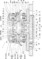
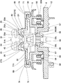
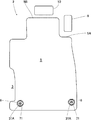
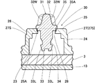
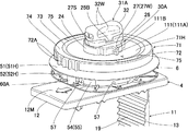
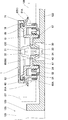
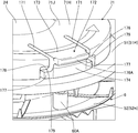
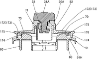
本発明の実施例1を示す固定構造の全体断面図である。It is a whole sectional view of the fixed structure which shows Example 1 of the present invention. 同上、中間回転ノブが非ロック位置の全体断面図である。FIG. 6 is an overall cross-sectional view of the intermediate rotation knob in the unlocked position. 同上、フロア回転ノブがロック位置の断面図である。The floor rotation knob is a cross-sectional view of the lock position. 同上、フロア回転ノブが非ロック位置の断面図である。FIG. 5 is a cross-sectional view of the floor rotation knob in the non-lock position. 同上、貫通孔の平面図である。It is a top view of a through-hole same as the above. 同上、第一マット本体を敷設した状態の平面図である。It is a top view of the state which laid the 1st mat main body same as the above. 同上、第一マット固定部材の要部の断面図である。It is a sectional view of the important section of the 1st mat fixation member same as the above. 同上、第一挿入受け部にフロア回転ノブを係止した状態の断面図である。It is sectional drawing of the state which latched the floor rotation knob to the 1st insertion receiving part same as the above. 同上、分解斜視図である。It is an exploded perspective view same as the above. 同上、第一マット及び第二マット固定部材の下部半体の斜視図である。It is a perspective view of the lower half of a 1st mat and a 2nd mat fixing member same as the above. 同上、フロア固定部材の斜視図である。It is a perspective view of a floor fixing member same as the above. 同上、フロア固定部材と第一マット固定部材の斜視図である。It is a perspective view of a floor fixing member and a 1st mat fixing member same as the above. 同上、フロア固定部材と第一マット固定部材と中間部材の斜視図である。It is a perspective view of a floor fixing member, a 1st mat fixing member, and an intermediate member same as the above. 同上、全体斜視図である。It is a whole perspective view same as the above. 同上、位置決め突起と係合溝部周りの拡大断面説明図である。It is an expanded sectional explanatory view around a positioning protrusion and an engaging groove part same as the above. 同上、中間部材を下から見た斜視図である。It is the perspective view which looked at the intermediate member from the bottom same as the above. 同上、一部を切り欠いた係止構造の斜視図である。It is a perspective view of the locking structure which a part cut out same as the above. 同上、第一マット固定部材の上部半体の斜視図である。It is a perspective view of the upper half of a 1st mat fixing member same as the above. 同上、ノブ係止受け部周りの斜視図である。It is a perspective view around a knob latching receiving part same as the above. 同上、ノブ係止受け部の規制用突起部にフロア回転ノブが当接した状態の斜視図である。It is a perspective view of the state which the floor rotation knob contact | abutted to the projection part for regulation of a knob latching receiving part same as the above. 同上、ノブ係止受け部にフロア回転ノブが係止した状態の斜視図である。It is a perspective view of the state which the floor rotation knob latched to the knob latching receiving part same as the above. 同上、フロア固定部材への第一マット固定部材と中間部材の取付を説明する平面である。It is a plane explaining the attachment of the 1st mat fixing member and intermediate member to a floor fixing member same as the above. 同上、中間回転ノブの操作を説明する平面図である。It is a top view explaining operation of an intermediate rotation knob same as the above. 本発明の実施例2を示すノブ係止受け部の規制用突起部にフロア回転ノブが係止した状態の斜視図である。It is a perspective view in the state where the floor rotation knob was locked to the restricting projection of the knob lock receiving portion showing Embodiment 2 of the present invention. 本発明の実施例3を示すノブ係止受け部の規制用突起部にフロア回転ノブが係止した状態の斜視図である。It is a perspective view in the state where the floor rotation knob locked to the projection for regulation of the knob locking receiving part which shows Example 3 of the present invention. 本発明の実施例4を示す係止位置確認構造を説明する平面図である。It is a top view explaining the locking position confirmation structure which shows Example 4 of this invention. 同上、第一マット固定部材の平面図である。It is a top view of a 1st mat fixing member same as the above. 本発明の実施例5を示す係止位置確認構造を説明する平面図である。It is a top view explaining the locking position confirmation structure which shows Example 5 of this invention. 同上、第一マット固定部材の平面図である。It is a top view of a 1st mat fixing member same as the above. 本発明の実施例6を示す係止位置確認構造を説明する平面図である。It is a top view explaining the latching position confirmation structure which shows Example 6 of this invention. 本発明の実施例7を示す中間部材の変形例を示す斜視図である。It is a perspective view which shows the modification of the intermediate member which shows Example 7 of this invention. 本発明の実施例8を示す固定構造の断面図である。It is sectional drawing of the fixing structure which shows Example 8 of this invention. 同上、固定構造を備えた容器本体の斜視図である。It is a perspective view of the container main body provided with the fixing structure same as the above. 本発明の実施例9を示す分解斜視図である。It is a disassembled perspective view which shows Example 9 of this invention. 同上、弾性片回りの斜視図である。It is a perspective view around an elastic piece same as the above. 同上、中間部材の平面図である。It is a top view of an intermediate member same as the above. 同上、中間部材の底面図である。It is a bottom view of an intermediate member same as the above. 同上、第一マット固定部材の平面図である。It is a top view of a 1st mat fixing member same as the above. 同上、挿通部に中間係止受け部を挿通した状態の平面図である。It is a top view of the state which inserted the intermediate | middle latching receiving part in the insertion part same as the above. 同上、挿通部に中間係止受け部を挿通した状態の第一マット固定部材の上部半体と中間部材の断面図である。FIG. 6 is a cross-sectional view of the upper half of the first mat fixing member and the intermediate member in a state where the intermediate latch receiving portion is inserted through the insertion portion. 同上、第一係止部に固定用凸部の下端を当接した状態の断面図である。It is sectional drawing of the state which contact | abutted the lower end of the convex part for fixation to the 1st latching | locking part same as the above. 同上、挿通部に固定用凸部を嵌合した状態の平面図であるIt is a top view of the state which fitted the convex part for fixation to the insertion part same as the above. 同上、一部を切り欠いた弾性片周りの斜視図である。It is a perspective view around the elastic piece which a part cut out same as the above. 同上、挿通部に固定用凸部を嵌合した状態の第一マット固定部材の上部半体と中間部材の断面図である。FIG. 5 is a cross-sectional view of the upper half and the intermediate member of the first mat fixing member in a state where the fixing convex portion is fitted to the insertion portion. 本発明の実施例10を示す弾性片周りの斜視図である。It is a perspective view around an elastic piece showing Example 10 of the present invention. 同上、確認手段周りの斜視図である。It is a perspective view around a confirmation means same as the above. 同上、第一マット固定手段に中間部材を取り付けた状態の平面図である。It is a top view of the state which attached the intermediate member to the 1st mat fixing means same as the above. 本発明の実施例11を示す第一固定手段に中間部材を取り付けた状態の平面図である。It is a top view of the state which attached the intermediate member to the 1st fixing means which shows Example 11 of this invention.

以下、図面を参照して、本発明の車両用フロアマットの固定構造及び部材への固定構造の実施例について説明する。   DESCRIPTION OF EMBODIMENTS Hereinafter, embodiments of a vehicle floor mat fixing structure and member fixing structure according to the present invention will be described with reference to the drawings.

図1〜図23は本発明の実施例1を示し、同図に示すように、車両用フロアマットの固定構造1は、車両のフロア2に設けた車両側カーペット3に固定したフロア固定部材4と、前記車両側カーペット3上に着脱可能に敷設する第一マット本体5と、この第一マット本体5に固定され前記フロア固定部材4に着脱可能に固定される第一マット固定部材6と、前記第一マット本体5上に着脱可能に敷設する第二マット本体7と、この第二マット本体7に固定され前記第一マット固定部材6に着脱可能に固定される第二マット固定部材8と、前記フロア固定部材4と第一マット固定部材6の間に設けるアタッチメントたる中間部材71とを備える。   1 to 23 show a first embodiment of the present invention. As shown in FIG. 1, a vehicle floor mat fixing structure 1 is a floor fixing member 4 fixed to a vehicle side carpet 3 provided on a vehicle floor 2. A first mat body 5 detachably laid on the vehicle-side carpet 3; a first mat fixing member 6 fixed to the first mat body 5 and detachably fixed to the floor fixing member 4; A second mat body 7 detachably laid on the first mat body 5; a second mat fixing member 8 fixed to the second mat body 7 and detachably fixed to the first mat fixing member 6; And an intermediate member 71 serving as an attachment provided between the floor fixing member 4 and the first mat fixing member 6.

また、前記フロア固定部材4,第一マット固定部材6,第二マット固定部材8及び中間部材71は合成樹脂製であって、この合成樹脂としては、POM(ポリアセタール)などが例示される。また、前記フロア固定部材4,第一マット固定部材6及び第二マット固定部材8,フロア回転ノブ31及び中間回転ノブ31Aにより、第一,第二マット本体5,7の固定構造1を構成している。尚、車両側カーペット3は車両に固定されている。   The floor fixing member 4, the first mat fixing member 6, the second mat fixing member 8 and the intermediate member 71 are made of synthetic resin. Examples of the synthetic resin include POM (polyacetal). The floor fixing member 4, the first mat fixing member 6 and the second mat fixing member 8, the floor rotation knob 31 and the intermediate rotation knob 31A constitute a fixing structure 1 for the first and second mat bodies 5 and 7. ing. The vehicle side carpet 3 is fixed to the vehicle.

車両側カーペット3が板状の部材であり、フロア固定部材4が固定部材であり、また、第一マット本体5が板状の第一部材であり、第一マット固定部材6が第一固定部材である。さらに、フロア回転ノブ31が回転ノブである。   The vehicle side carpet 3 is a plate-like member, the floor fixing member 4 is a fixing member, the first mat body 5 is a plate-like first member, and the first mat fixing member 6 is a first fixing member. It is. Further, the floor rotation knob 31 is a rotation knob.

また、第二マット本体7が板状の第二部材であり、第二マット固定部材8が第二固定部材である。尚、中間部材71がカバー部材である。   The second mat body 7 is a plate-like second member, and the second mat fixing member 8 is a second fixing member. The intermediate member 71 is a cover member.

図2ではフロア固定部材4のフロア回転ノブ31により、フロア固定部材4に第一マット固定部材6が固定され、第一マット固定部材6に中間部材71が固定され、一方、中間部材71の中間回転ノブ31Aに対して第二マット固定部材8は非固定状態である。   In FIG. 2, the first mat fixing member 6 is fixed to the floor fixing member 4 by the floor rotation knob 31 of the floor fixing member 4, and the intermediate member 71 is fixed to the first mat fixing member 6. The second mat fixing member 8 is not fixed to the rotation knob 31A.

また、前記第一マット本体5は、下部に設けられたゴムなどからなるシート状のベース層(図示せず)と、上部に設けられたパイルや毛からなるカーペット(図示せず)とを備え、そのパイルや毛の上端は自由端に形成されている。   The first mat body 5 includes a sheet-like base layer (not shown) made of rubber or the like provided in the lower part, and a carpet (not shown) made of pile or hair provided in the upper part. The upper ends of the piles and hairs are formed at the free ends.

さらに、第二マット本体7は合成樹脂又はゴムなどからなり、熱可塑性樹脂(例えば、ポリ塩化ビニル、エチレン−酢酸ビニル共重合体、ポリエチレンなど)、熱可塑性エラストマー(例えば、スチレン系熱可塑性エラストマー、ポリオレフィン系熱可塑性エラストマー、ポリ塩化ビニル系エラストマーなど)、熱硬化性樹脂(例えば、フェノール樹脂、ポリウレタン、不飽和ポリエステル樹脂など)、或いは天然又は合成ゴム(例えば、スチレン−ブタジエンゴム、ブタジエンゴム、イソプレンゴム、ニトリル−ブタジエンゴムなど)などを挙げることができる。これらの中でも、軽量かつリサイクルし易い熱可塑性エラストマーからなるのが好まく、さらに、弾力性を備えることが好ましい。また、第二マット本体7の硬度(ショアーA硬度)は、50〜90程度であるのが好ましく、65〜75程度であるのがより好ましい。   Further, the second mat body 7 is made of a synthetic resin or rubber, and is made of a thermoplastic resin (for example, polyvinyl chloride, ethylene-vinyl acetate copolymer, polyethylene, etc.), a thermoplastic elastomer (for example, a styrenic thermoplastic elastomer, Polyolefin thermoplastic elastomer, polyvinyl chloride elastomer, etc.), thermosetting resin (eg, phenol resin, polyurethane, unsaturated polyester resin, etc.), or natural or synthetic rubber (eg, styrene-butadiene rubber, butadiene rubber, isoprene). Rubber, nitrile-butadiene rubber, etc.). Among these, it is preferable to be made of a thermoplastic elastomer that is lightweight and easy to recycle, and more preferably has elasticity. Moreover, it is preferable that the hardness (Shore A hardness) of the 2nd mat main body 7 is about 50-90, and it is more preferable that it is about 65-75.

また、第二マット本体7は第一マット本体5より防水性に優れると共に、第二マット本体7の上面は第一マット本体5の上面より濡れ性が低い。即ち、第一マット本体5の上面は、カーペットのパイルや毛により濡れ易く、第二マット本体7は合成樹脂やゴムからなるため第一マット本体5より撥水性に優れる。   The second mat body 7 is more waterproof than the first mat body 5, and the upper surface of the second mat body 7 is less wettable than the upper surface of the first mat body 5. That is, the upper surface of the first mat body 5 is easily wetted by carpet piles and hairs, and the second mat body 7 is made of a synthetic resin or rubber, so that it has better water repellency than the first mat body 5.

図6において、前記第一マット本体5は、車両の運転席側のフロア2に敷設されるものを例示している。前記フロア2の運転側には、右側に前後方向(一側方向)に長いアクセルペダル9が配置され、このアクセルペダル9の左側には、左右方向(他側方向)に長いブレーキペダル10が配置されている。また、前記第一マット本体5の前右角部には、前記アクセルペダル9に対応して凹部5Aが設けられている。さらに、前記第一マット本体5の前端縁5Bが前記ブレーキペダル10に近接配置されていると共に、前記第一マット本体5の前端縁5Bと前記ブレーキペダル10との間に間隔を設けており、この間隔により第一マット本体5と前記ブレーキペダル10が干渉しないように配置されている。   In FIG. 6, the first mat body 5 is laid on the floor 2 on the driver's seat side of the vehicle. On the driving side of the floor 2, a long accelerator pedal 9 is disposed on the right side in the front-rear direction (one side direction), and on the left side of the accelerator pedal 9, a long brake pedal 10 is disposed in the left-right direction (the other side direction). Has been. Further, a concave portion 5 </ b> A is provided at the front right corner of the first mat body 5 corresponding to the accelerator pedal 9. Furthermore, the front end edge 5B of the first mat body 5 is disposed close to the brake pedal 10, and a space is provided between the front end edge 5B of the first mat body 5 and the brake pedal 10. The first mat body 5 and the brake pedal 10 are arranged so as not to interfere with each other due to this interval.

図3に示すように、前記フロア固定部材4は、車両側カーペット3に固定するカーペット固定部11を備える。このカーペット固定部11は、車両側カーペット3の上面に配置する平板状の上ベース部12と、車両側カーペット3の下面に配置され前記上ベース部12との間に車両側カーペット3を挟む下挟着部13とを備える。前記上ベース部12の平面形状は略長方形であり、前記下挟着部13の平面形状は前記上ベース部12と同一方向に長い略長方形であり、前記下挟着部13は前記上ベース部12より小さく形成されている。また、図11に示すように、前記上ベース部12の上面には向きを示す印12Mが設けられ、この印12Mは矢印の形をなすものであって、車両の前方を示している。   As shown in FIG. 3, the floor fixing member 4 includes a carpet fixing portion 11 that fixes the vehicle side carpet 3. The carpet fixing portion 11 is disposed on the upper surface of the vehicle-side carpet 3 and the lower surface of the vehicle-side carpet 3. And a sandwiching portion 13. The planar shape of the upper base portion 12 is substantially rectangular, the planar shape of the lower sandwiching portion 13 is a substantially rectangular shape that is long in the same direction as the upper base portion 12, and the lower sandwiching portion 13 is the upper base portion. It is smaller than 12. Further, as shown in FIG. 11, a mark 12M indicating a direction is provided on the upper surface of the upper base portion 12, and this mark 12M has an arrow shape and indicates the front of the vehicle.

前記上ベース部12の下面には、長さ方向一側に挿通部14が突設され、この挿通部14の下端に前記下挟着部13の長さ方向一端を連結し、前記挿通部14と前記下挟着部13との間には薄肉状のヒンジ部15が設けられている。また、前記下挟着部13の長さ方向他端側には、弾性爪片16を上向きに突設し、この弾性爪片16が弾発的に連結する爪受け部17が、前記上ベース部12の下面に設けられている。さらに、その爪受け部17より外側に位置して、前記下挟着部13の他端には上側に屈曲した立上り部18を設けており、固定状態で前記立上り部18の内側に前記爪受け部17が隠れる。また、前記下挟着部13の上面には複数の凹凸部19が形成され、左右方向の凹凸部19が前後方向に並んで設けられている。そして、前記弾性爪片16と前記爪受け部17とにより、上ベース部12と下挟着部13の他側を弾発的に連結するフロア固定部材4の連結部20を構成している。   On the lower surface of the upper base portion 12, an insertion portion 14 projects from one side in the length direction, and one end in the length direction of the lower sandwiching portion 13 is connected to the lower end of the insertion portion 14, and the insertion portion 14 A thin-walled hinge portion 15 is provided between the lower sandwiching portion 13 and the lower sandwiching portion 13. Further, an elastic claw piece 16 protrudes upward on the other end in the lengthwise direction of the lower clamping part 13, and a claw receiving part 17 to which the elastic claw piece 16 is elastically connected is provided on the upper base. It is provided on the lower surface of the part 12. Furthermore, a rising portion 18 that is bent upward is provided at the other end of the lower sandwiching portion 13 that is located outside the claw receiving portion 17, and the claw receiving portion 18 is provided inside the rising portion 18 in a fixed state. Part 17 is hidden. A plurality of uneven portions 19 are formed on the upper surface of the lower sandwiching portion 13, and the uneven portions 19 in the left-right direction are provided side by side in the front-rear direction. The elastic claw piece 16 and the claw receiving portion 17 constitute a connecting portion 20 of the floor fixing member 4 that elastically connects the upper base portion 12 and the other side of the lower sandwiching portion 13.

図3に示すように、前記フロア固定部材4の取付位置に対応して、車両側カーペット3には、前後で対をなす一方及び他方の挿通孔21,22が穿設されている。   As shown in FIG. 3, corresponding to the mounting position of the floor fixing member 4, one and the other insertion holes 21, 22 that form a pair in the front and rear are formed in the vehicle side carpet 3.

そして、車両側カーペット3の上方から一方の挿通孔21に前記下挟着部13を挿通すると共に、他方の挿通孔22に前記爪受け部17を挿入し、この挿通した前記下挟着部13を、前記ヒンジ部15を中心にカーペット3の下面側に折曲げ、先端の前記弾性爪片16を前記爪受け部17に弾発的に係止することにより、前記上ベース部12と前記下挟着部13が車両側カーペット3を上下から挟着し、フロア固定部材4が車両側カーペット3に固定される。   Then, the lower clamping part 13 is inserted into one insertion hole 21 from above the vehicle side carpet 3, and the claw receiving part 17 is inserted into the other insertion hole 22, and the inserted lower clamping part 13 is inserted. Is bent to the lower surface side of the carpet 3 with the hinge portion 15 as the center, and the elastic claw piece 16 at the tip is elastically locked to the claw receiving portion 17 so that the upper base portion 12 and the lower base portion 12 are The sandwiching portion 13 sandwiches the vehicle side carpet 3 from above and below, and the floor fixing member 4 is fixed to the vehicle side carpet 3.

前記固定状態で、前記弾性爪片16,爪受け部17及び立上り部18は、他方の挿通孔22内に収納され、前記爪受け部17は弾性爪片16と立上り部18により挟まれているから、前記爪受け部17が他方の挿通孔22の内縁に当たることがない。また、前記弾性爪片16が他方の挿通孔22の内縁に当たっても前記弾性爪片16は係止方向に押されるから、前記爪受け部17から弾性爪片16が外れることがない。さらに、固定状態で車両側カーペット3の下面には前記凹凸部19が当接しているから、車両側カーペット3に対するフロア固定部材4の位置ずれを防止できる。   In the fixed state, the elastic claw piece 16, the claw receiving portion 17 and the rising portion 18 are accommodated in the other insertion hole 22, and the claw receiving portion 17 is sandwiched between the elastic claw piece 16 and the rising portion 18. Therefore, the claw receiving portion 17 does not hit the inner edge of the other insertion hole 22. Even when the elastic claw piece 16 hits the inner edge of the other insertion hole 22, the elastic claw piece 16 is pushed in the locking direction, so that the elastic claw piece 16 does not come off from the claw receiving portion 17. Furthermore, since the uneven portion 19 is in contact with the lower surface of the vehicle-side carpet 3 in the fixed state, the displacement of the floor fixing member 4 with respect to the vehicle-side carpet 3 can be prevented.

前記フロア固定部材4には、フロア回転ノブ31を装着するノブ装着部分30が設けられている。以下、ノブ装着部分30の構成について説明する。前記上ベース部12の略中央には貫通孔23が穿設されていると共に、この貫通孔23に連通する筒部24が上ベース部12から上方に突設されている。図11などに示すように、前記筒部24の上部の中央に一段高い中央上面25を設けている。この中央上面25はフロア固定部材4の幅方向(左右方向)に長く形成され、その中央上面25の下部周囲には係入部たる係入外周部26が設けられ、この係入外周部26の下部に前記中央上面25より一段低い横方向の段差面27が周設され、この段差面27は、前記中央上面25の幅方向両側が長さ方向両側より広く形成されている。即ち、段差面27の幅広部27W(図8)が中央上面25の幅方向両側に設けられ、段差面27の幅狭部27S(図7)が中央上面25の長さ方向両側に設けられている。また、前記中央上面25の略中央には該中央上面25と同一方向に長い長孔28が穿設されている。   The floor fixing member 4 is provided with a knob mounting portion 30 for mounting a floor rotation knob 31. Hereinafter, the configuration of the knob mounting portion 30 will be described. A through hole 23 is bored at substantially the center of the upper base portion 12, and a cylindrical portion 24 communicating with the through hole 23 is projected upward from the upper base portion 12. As shown in FIG. 11 and the like, a central upper surface 25 that is one step higher is provided at the center of the upper portion of the cylindrical portion 24. The central upper surface 25 is formed long in the width direction (left-right direction) of the floor fixing member 4, and an engaging outer peripheral portion 26 as an engaging portion is provided around the lower portion of the central upper surface 25. A stepped surface 27 in the lateral direction that is one step lower than the central upper surface 25 is provided around the stepped surface 27. Both sides of the central upper surface 25 in the width direction are formed wider than both sides in the lengthwise direction. That is, the wide portions 27W (FIG. 8) of the step surface 27 are provided on both sides of the central upper surface 25 in the width direction, and the narrow portions 27S (FIG. 7) of the step surface 27 are provided on both sides of the central upper surface 25 in the length direction. Yes. In addition, a long hole 28 that is long in the same direction as the central upper surface 25 is formed in the approximate center of the central upper surface 25.

図11及び図22(A)に示すように、前記筒部24の下部には前後に凹部24A,24Aを形成すると共に、この凹部24Aの中央に位置決め突起111を設けている。前記凹部24Aの底部は直線状をなし、前記突起上部111Bの先端は筒部24の外周に対応した位置に設けられ、即ち、突起上部111Bの先端は筒部24の半径位置に設けられている。以上がノブ装着部分30の主要な構成である。   As shown in FIGS. 11 and 22 (A), recesses 24A and 24A are formed in the front and rear of the cylindrical portion 24, and a positioning projection 111 is provided at the center of the recess 24A. The bottom of the recess 24A is linear, and the tip of the protrusion upper portion 111B is provided at a position corresponding to the outer periphery of the tube portion 24. That is, the tip of the protrusion upper portion 111B is provided at the radial position of the tube portion 24. . The above is the main configuration of the knob mounting portion 30.

また、前記上ベース部12の下面には前記貫通孔23を挟んだ両側に凹凸部29が形成されている。   Further, on the lower surface of the upper base portion 12, uneven portions 29 are formed on both sides of the through hole 23.

前記フロア固定部材4の前記上ベース部12の前記筒部24には、合成樹脂製のフロア回転ノブ31が回転可能に軸支され、このフロア固定部材4に設けたフロア回転ノブ31が、前記第一マット固定部材6に係止するフロア側係止部である。   A synthetic resin floor rotation knob 31 is rotatably supported on the cylindrical portion 24 of the upper base portion 12 of the floor fixing member 4, and the floor rotation knob 31 provided on the floor fixing member 4 includes the above-described floor rotation knob 31. It is a floor-side locking portion that locks to the first mat fixing member 6.

前記フロア回転ノブ31は、上部に操作子32を有すると共に、下部に抜止め連結部たる連結保持部33を有し、前記操作子32と前記連結保持部33の間に、軸部たる中部34を一体に有する。前記操作子32は前記中央上面25に摺動する長さ方向のベース部35を有する。また、操作子32は、その平面形状が前記ベース部35の長さ方向に長く形成されており、幅方向両側面に凹部たる凹状湾曲面32W,32Wが形成され、図7などに示すように、操作子32は両側の凹状湾曲面32W,32Wに挟まれた長さ中央部分が長さ方向両端側部分より幅狭に形成されている。   The floor rotation knob 31 has an operation element 32 at the upper part and a connection holding part 33 as a retaining connection part at the lower part, and a middle part 34 as a shaft part between the operation element 32 and the connection holding part 33. Are integrated. The operation element 32 has a base portion 35 in the length direction that slides on the central upper surface 25. The operating element 32 has a planar shape that is long in the length direction of the base portion 35, and concave curved surfaces 32W and 32W that are concave portions are formed on both side surfaces in the width direction, as shown in FIG. The operation element 32 is formed such that the central part of the length sandwiched between the concave curved surfaces 32W and 32W on both sides is narrower than both end parts in the length direction.

また、図7などに示すように、前記フロア回転ノブ31の前記ベース部35の下面には、前記中部34を中心とした円形座面35Aが突出形成され、この円形座面35Aに対応して、前記筒部24の前記中央上面25に円形凹部25Aが形成され、この円形凹部25Aは前記長孔28の上部に形成されている。そして、前記円形凹部25Aに前記円形座面35Aが係入し、この係入状態で前記フロア回転ノブ31が回転操作される。尚、円形凹部25Aの幅方向両側は、前記係入外周部26の幅方向両側の中央に設けた開口部25B,25Bにより開口している(図11)。   Further, as shown in FIG. 7 and the like, a circular seat surface 35A centering on the middle portion 34 is formed on the lower surface of the base portion 35 of the floor rotating knob 31 so as to correspond to the circular seat surface 35A. A circular recess 25A is formed in the central upper surface 25 of the cylindrical portion 24, and the circular recess 25A is formed in the upper part of the long hole 28. Then, the circular seat surface 35A is engaged with the circular recess 25A, and the floor rotating knob 31 is rotated in this engaged state. Note that both sides in the width direction of the circular recess 25A are opened by openings 25B and 25B provided in the center on both sides in the width direction of the engaging outer peripheral portion 26 (FIG. 11).

前記中部34は、断面が非円形で、この例では断面略正方形であり、角を面取りした湾曲角部を備え、隣り合う湾曲角部の間に直線部が形成されている。   The middle part 34 has a non-circular cross section, and in this example has a substantially square cross section. The middle part 34 includes curved corners with chamfered corners, and a linear part is formed between adjacent curved corners.

前記連結保持部33は、前記操作子32と同一方向に長く形成され、その上面33Uが前記中部34より幅広であり、下方に向って幅狭に形成されている。具体的には、前記連結保持部33は、対をなす長さ方向の側面33L,33L間が下方に向かって狭まり(図7)、対をなす幅方向の側面33W,33W間が下方に向かって狭まる形状をなす(図8)。   The connection holding portion 33 is formed to be long in the same direction as the operation element 32, and its upper surface 33U is wider than the middle portion 34 and is formed narrower toward the lower side. Specifically, the connecting and holding portion 33 is narrowed downward between the paired length side surfaces 33L and 33L (FIG. 7), and the paired width side surfaces 33W and 33W are directed downward. To form a narrow shape (FIG. 8).

前記フロア回転ノブ31の下部は、前記長孔28から前記筒部24内に挿入される。前記フロア固定部材4には、前記フロア回転ノブ31を抜け止め状態で係止すると共に回転自在に軸支するノブ受け部40が設けられている(図8)。尚、前記ノブ装着部分30は前記ノブ受け部40を備える。   A lower portion of the floor rotation knob 31 is inserted into the cylindrical portion 24 through the long hole 28. The floor fixing member 4 is provided with a knob receiving portion 40 that locks the floor rotation knob 31 in a retaining state and supports it rotatably (FIG. 8). The knob mounting portion 30 includes the knob receiving portion 40.

前記ノブ受け部40には、前記フロア回転ノブ31の前記中部34が係合する保持壁部43,43が設けられており、これら両側の保持壁部43,43間に挟まれて前記中部34が保持される。また、前記保持壁部43,43は内側に張り出して形成され、保持壁部43は、前記中部34の回転により該中部34から荷重を受ける。   The knob receiving portion 40 is provided with holding wall portions 43, 43 with which the middle portion 34 of the floor rotating knob 31 is engaged. The middle portion 34 is sandwiched between the holding wall portions 43, 43 on both sides. Is retained. Further, the holding wall portions 43 and 43 are formed to protrude inward, and the holding wall portion 43 receives a load from the middle portion 34 by the rotation of the middle portion 34.

そして、組立時には、フロア回転ノブ31の連結保持部33を長孔28に挿通して保持壁部43,43間に挿入すると、連結保持部33が保持壁部43,43間に圧入されると共に、保持壁部43,43間が弾性変形して開き、連結保持部33が保持壁部43,43間を通過すると、保持壁部43,43が復帰し、抜け止め状態となり、フロア回転ノブ31の円形座面35Aが長孔28の上部の円形凹部25Aに係入する。   At the time of assembly, when the connection holding portion 33 of the floor rotation knob 31 is inserted through the long hole 28 and inserted between the holding wall portions 43 and 43, the connection holding portion 33 is press-fitted between the holding wall portions 43 and 43. The holding wall portions 43 and 43 are elastically deformed to open, and when the connection holding portion 33 passes between the holding wall portions 43 and 43, the holding wall portions 43 and 43 are restored to be in a retaining state, and the floor rotation knob 31 The circular seating surface 35A engages with the circular recess 25A at the top of the long hole 28.

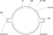
次に、前記車両側カーペット3に固定する前記第一マット固定部材6の詳細について説明する。図9などに示すように、前記第一マット固定部材6は、前記第一マット本体5を上下から挟んで組み付けられる上部半体51と下部半体52とを備える。前記上部半体51の本体51Hは、略円形状をなし、その本体51Hの上面51Jは平坦に形成されている。また、上部半体51の本体51Hには、上連結筒部53が中央から下方に突設されている。一方、前記下部半体52の本体52Hは略正方形形状をなし、前記上連結筒部53に連結する下連結筒部54が中央から上方に突設されている。尚、下連結筒部54は本体52Hの開口部54Aに設けられている。そして、前記上連結筒部53と下連結筒部54により、半体連結部55を構成している。   Next, details of the first mat fixing member 6 fixed to the vehicle side carpet 3 will be described. As shown in FIG. 9 and the like, the first mat fixing member 6 includes an upper half 51 and a lower half 52 that are assembled by sandwiching the first mat body 5 from above and below. The main body 51H of the upper half 51 has a substantially circular shape, and the upper surface 51J of the main body 51H is formed flat. In addition, an upper connecting cylinder portion 53 projects downward from the center of the main body 51H of the upper half 51. On the other hand, the main body 52H of the lower half 52 has a substantially square shape, and a lower connecting cylinder portion 54 connected to the upper connecting cylinder portion 53 is provided so as to protrude upward from the center. The lower connecting cylinder portion 54 is provided in the opening 54A of the main body 52H. The upper connecting cylinder part 53 and the lower connecting cylinder part 54 constitute a half body connecting part 55.

図1及び図2などに示すように、前記上連結筒部53の外周には、係止鍔部56を多段に周設し、この係止鍔部56は、その下面が内側から外側に向って高くなるように傾斜すると共に、その上面が略水平をなしている。また、前記下連結筒部54には、下端が開口した複数の切欠き57,57を周方向に間隔を置いて設け、これら切欠き57,57間に、下端が自由端をなす係止受け片58を設け、この係止受け片58の下端内面に、前記係止鍔部56が係止する係止爪部59を設け、この係止爪部59は、その上面が内側から外側に向って高くなるように傾斜し、下面が略水平をなしている。尚、この例では、4つの係止受け片58が円周方向に等間隔で設けられている。また、係止鍔部56は、前記上連結筒部53の全周に設けてもよいし、前記係止爪部59に対応する箇所のみに設けてもよい。   As shown in FIGS. 1 and 2, etc., the upper connecting cylinder portion 53 is provided with a plurality of locking hook portions 56 on the outer periphery, and the lower surface of the locking hook portion 56 faces from the inside to the outside. And the upper surface is substantially horizontal. Further, the lower connecting cylinder portion 54 is provided with a plurality of notches 57, 57 having lower ends opened at intervals in the circumferential direction, and between the notches 57, 57, a latch receiver whose lower end forms a free end. A locking claw portion 59 is provided on the inner surface of the lower end of the locking receiving piece 58, and the locking claw portion 59 is locked to the locking claw portion 59. The lower surface is substantially horizontal. In this example, four locking receiving pieces 58 are provided at equal intervals in the circumferential direction. Further, the locking collar 56 may be provided on the entire circumference of the upper connecting cylinder 53, or may be provided only at a location corresponding to the locking claw 59.

さらに、図8等に示すように、前記上部半体51の本体51Hには、上,下連結筒部53,54を挟むようにして前後に係合ピン60,60が下方に突設されている。これら係合ピン60,60に対応して、前記下部半体52の本体52Hの前後には係合筒部60A,60Aが突設され、前記係合筒部60Aに前記係合ピン60が係入する。尚、逆に、上部半体51の本体51Hに係合筒部60Aを設け、下部半体52の本体52Hに係合ピン60を設けてもよい。   Further, as shown in FIG. 8 and the like, the main body 51H of the upper half 51 is provided with engaging pins 60, 60 projecting downward in the front-rear direction so as to sandwich the upper and lower connecting cylinder portions 53, 54 therebetween. Corresponding to these engaging pins 60, 60, engaging cylinder parts 60A, 60A are provided in front of and behind the main body 52H of the lower half 52, and the engaging pin 60 is engaged with the engaging cylinder part 60A. Enter. Conversely, the engagement cylinder 60A may be provided on the main body 51H of the upper half 51 and the engagement pin 60 may be provided on the main body 52H of the lower half 52.

そして、係止鍔部56と係止爪部59により、上連結筒部53と下連結筒部54とを連結する連結手段を構成している。   The engaging hook 56 and the engaging claw 59 constitute connecting means for connecting the upper connecting cylinder part 53 and the lower connecting cylinder part 54.

したがって、下連結筒部54内に上連結筒部53を挿入すると、係止受け片58が弾性変形して外側に移動し、所定の位置の係止鍔部56が係止爪部59に抜け止め状態で係止し、これにより上,下連結筒部53,54が連結される。   Therefore, when the upper connecting cylinder part 53 is inserted into the lower connecting cylinder part 54, the locking receiving piece 58 is elastically deformed and moves outward, and the locking hook part 56 at a predetermined position is pulled out to the locking claw part 59. The upper and lower connecting cylinder portions 53 and 54 are connected by locking in the stopped state.

図1及び図5などに示すように、前記第一マット本体5には、前記半体連結部55を挿入する中央貫通孔61が穿設されており、前記中央貫通孔61内において前記半体連結部55の連結を行うことによって、上,下部半体51,52により第一マット本体5を挟着した状態で、第一マット固定部材6を第一マット本体5に固定することができる。また、前記第一マット本体5には、前記係合筒部60A,60Aを挿入する外側貫通孔61A,61Aが穿設されており、図5に示すように、外側貫通孔61A,61Aは前記中央貫通孔61に連通し、前記外側貫通孔61A,61A内において前記係合筒部60Aに前記係合ピン60を係入する。尚、外側貫通孔61Aは平面において中央貫通孔61の外周から突出するように形成されている。また、外側貫通孔61Aを中央貫通孔61に連通しないように別個に設けてもよい。   As shown in FIGS. 1 and 5, the first mat body 5 is provided with a central through hole 61 into which the half connecting portion 55 is inserted, and the half body is inserted into the central through hole 61. By connecting the connecting portions 55, the first mat fixing member 6 can be fixed to the first mat body 5 in a state where the first mat body 5 is sandwiched between the upper and lower halves 51 and 52. Further, the first mat body 5 is provided with outer through holes 61A and 61A for inserting the engaging tube portions 60A and 60A. As shown in FIG. 5, the outer through holes 61A and 61A are formed as described above. The engaging pin 60 is engaged with the engaging cylinder portion 60A in the outer through holes 61A and 61A. The outer through hole 61A is formed so as to protrude from the outer periphery of the central through hole 61 in a plane. Further, the outer through hole 61A may be provided separately so as not to communicate with the central through hole 61.

さらに、図9などに示すように、前記上部半体51の本体51Hの周囲下面には前記第一マット本体5に挿入係止するピン62を複数設けると共に、前記下部半体52の本体52Hの周囲上面には前記第一マット本体5に挿入係止するピン63を複数設け、それらピン62,63により前記第一マット本体5に対して第一マット固定部材6を回り止め状態で固定することができる。また、中央貫通孔61の両側に位置する前記外側貫通孔61A,61A内において前記係合筒部60Aに前記係合ピン60を係入するため、前記第一マット本体5に対して第一マット固定部材6を確実に回り止めすることができる。   Further, as shown in FIG. 9 and the like, a plurality of pins 62 inserted and locked to the first mat main body 5 are provided on the lower peripheral surface of the main body 51H of the upper half 51, and the main body 52H of the lower half 52 is formed. A plurality of pins 63 that are inserted and locked to the first mat body 5 are provided on the peripheral upper surface, and the first mat fixing member 6 is fixed to the first mat body 5 with the pins 62 and 63 in a non-rotating state. Can do. Further, in order to engage the engagement pin 60 in the engagement cylinder portion 60A in the outer through holes 61A, 61A located on both sides of the central through hole 61, the first mat is inserted into the first mat body 5. The fixing member 6 can be reliably prevented from rotating.

また、前記上連結筒部53内には、フロア側係止部たる前記フロア回転ノブ31が係止可能な第一挿入受け部65が設けられている。この第一挿入受け部65は、前記上連結筒部53内に設けられ該上連結筒部53より小さな受け長孔66と、この受け長孔66の幅方向両側に設けた仕切り板状の係止受け部67,67とを備え、前記受け長孔66は前記フロア回転ノブ31の操作子32が挿通可能な大きさを有する。そして、前記受け長孔66に前記筒部24の前記中央上面25が下から係入し、図2,図4及び図22(A)(B)などに示すように、その受け長孔66に前記係入外周部26が係入し、これにより第一マット固定部材6がフロア固定部材4に対して回転することが防止され、且つフロア固定部材4に対する第一マット固定部材6の向きが規定される。また、前記受け長孔66に前記係入外周部26が係入した状態で、前記受け長孔66の幅方向両側の前記係止受け部67の下面が前記段差面27に当接し、フロア固定部材4に第一マット固定部材6が位置合わせされる。この状態でフロア回転ノブ31を平面略90度回すと、前記係止受け部67の上面に、ロック位置の前記操作子32が係止する。尚、この場合の係止とは、係止受け部67と操作子32が当接する必要は無く、図1及び図8に示すように、操作子32により係止受け部67が抜け止め状態となればよい。   Further, in the upper connecting cylinder portion 53, a first insertion receiving portion 65 capable of locking the floor rotation knob 31 serving as a floor side locking portion is provided. The first insertion receiving portion 65 includes a receiving long hole 66 provided in the upper connecting cylindrical portion 53 and smaller than the upper connecting cylindrical portion 53, and a partition plate-like engagement provided on both sides of the receiving long hole 66 in the width direction. The receiving slot 67 has a size that allows the operator 32 of the floor rotation knob 31 to be inserted therethrough. Then, the central upper surface 25 of the cylindrical portion 24 is engaged with the receiving long hole 66 from below, and the receiving long hole 66 is inserted into the receiving long hole 66 as shown in FIGS. The engaging outer peripheral portion 26 is engaged, whereby the first mat fixing member 6 is prevented from rotating with respect to the floor fixing member 4, and the orientation of the first mat fixing member 6 with respect to the floor fixing member 4 is defined. Is done. In addition, with the engaging outer peripheral portion 26 engaged with the receiving long hole 66, the lower surfaces of the locking receiving portions 67 on both sides in the width direction of the receiving long hole 66 abut against the step surface 27, and the floor is fixed. The first mat fixing member 6 is aligned with the member 4. In this state, when the floor rotation knob 31 is turned approximately 90 degrees in the plane, the operation element 32 in the locked position is locked to the upper surface of the locking receiving portion 67. In this case, the locking does not require the locking receiving portion 67 and the operating element 32 to come into contact with each other. As shown in FIGS. It only has to be.

図9などに示すように、前記位置決め突起111は、前記凹部24A及び前記上ベース部12の上面に一体に設けられた板片状をなす。また、位置決め突起111は、その突起下部111Aより左右方向に大きな突起上部111Bを有し、図15などに示すように、前記突起上部111Bの断面形状は略楕円形又は略円形をなす。   As shown in FIG. 9 and the like, the positioning protrusion 111 has a plate-like shape integrally provided on the upper surfaces of the concave portion 24A and the upper base portion 12. The positioning protrusion 111 has a protrusion upper portion 111B that is larger in the left-right direction than the protrusion lower portion 111A. As shown in FIG. 15 and the like, the cross-sectional shape of the protrusion upper portion 111B is substantially elliptical or substantially circular.

さらに、前記第一マット固定部材6及び第二マット固定部材8には、図15に示すように、前記位置決め突起111が係脱可能な係合溝部112が縦設され、この係合溝部112は、印81の位置に対応して、前記上連結筒部53内に設けられている。具体的には、前記上連結筒部53の内面に左右の縦壁部113,113を突設し、これら左右の縦壁部113,113の上端は前記係止受け部67の下面に連結され、それら左右の縦壁部113,113の間により係合溝部112を構成している。前記係合溝部112の下部には下方に向かって拡大する案内部112Aを設け、この案内部112Aの上部に係止部112Bを設け、この係止部112Bの幅より溝上部112Cの幅が広く形成されている。尚、係止部112Bの幅は前記突起上部111Bの最大左右寸法より小さい。   Further, as shown in FIG. 15, the first mat fixing member 6 and the second mat fixing member 8 are vertically provided with engaging groove portions 112 on which the positioning projections 111 can be engaged and disengaged. , Corresponding to the position of the mark 81, it is provided in the upper connecting cylinder portion 53. Specifically, left and right vertical wall portions 113, 113 project from the inner surface of the upper connecting cylinder portion 53, and the upper ends of the left and right vertical wall portions 113, 113 are connected to the lower surface of the locking receiving portion 67. The engagement groove 112 is constituted by the left and right vertical wall portions 113 and 113. A guide portion 112A that expands downward is provided at the lower portion of the engagement groove portion 112, and a locking portion 112B is provided above the guide portion 112A. The width of the groove upper portion 112C is wider than the width of the locking portion 112B. Is formed. The width of the locking portion 112B is smaller than the maximum left and right dimension of the protrusion upper portion 111B.

また、位置決め凸部たる前記位置決め突起111と位置決め凹部たる前記係合溝部112により、フロア固定部材4に対する第一マット固定部材6の抜け止め防止手段及び回転防止手段を構成している。   Further, the positioning projection 111 serving as a positioning convex portion and the engaging groove portion 112 serving as a positioning concave portion constitute a retaining prevention means and a rotation preventing means for the first mat fixing member 6 with respect to the floor fixing member 4.

そして、前記第一マット固定部材6及び第二マット固定部材8の受け長孔66に操作子32及び係入外周部26を挿入する際、案内部112Aに突起上部111Bが挿入され、この突起上部111Bが係止部112Bを通過する際に係止部112Bが広がるように弾性変形し、この際、クリック感が得られ、係止部112B間を通過した突起上部111Bが、溝上部112Cの間に抜け止め状態で保持される。これによる効果として、第一マット固定部材6の連結前でも、フロア固定部材4から第一マット固定部材6が浮き上がらず、その後のフロア回転ノブ31の回動操作を容易に行うことができる。一方、逆に、第一マット固定部材6を所定以上の力で持ち上げれば、突起上部111Bが係合溝部112から抜け、この際、係止部112Bが広がるように弾性変形してクリック感が得られる。また、筒部24の前後両側に位置決め突起111,111が設けられ、これら位置決め突起111,111を前記係合溝部112,112に挿入することにより、フロア固定部材4に対して、第一マット固定部材6が回り止め状態となる。また、中間部材71と第二マット固定部材8においても、同様な効果が得られる。   When the operating element 32 and the engaging outer peripheral portion 26 are inserted into the receiving long holes 66 of the first mat fixing member 6 and the second mat fixing member 8, the protrusion upper portion 111B is inserted into the guide portion 112A. When 111B passes through the locking portion 112B, the locking portion 112B is elastically deformed so that the locking portion 112B spreads. At this time, a click feeling is obtained, and the protruding upper portion 111B passing between the locking portions 112B is formed between the groove upper portions 112C. To be held in a state of retaining. As an effect of this, even before the first mat fixing member 6 is connected, the first mat fixing member 6 does not float from the floor fixing member 4, and the subsequent rotation operation of the floor rotation knob 31 can be easily performed. On the other hand, if the first mat fixing member 6 is lifted with a force of a predetermined level or more, the protrusion upper portion 111B comes out of the engaging groove 112, and at this time, the locking portion 112B is elastically deformed so that the click portion is spread. can get. In addition, positioning projections 111 and 111 are provided on both front and rear sides of the cylindrical portion 24. By inserting these positioning projections 111 and 111 into the engaging groove portions 112 and 112, the first mat is fixed to the floor fixing member 4. The member 6 is prevented from rotating. Further, the same effect can be obtained in the intermediate member 71 and the second mat fixing member 8.

前記フロア固定部材4の上部半体51の本体51Hの上面には、短筒部68が上方に突設され、この短筒部68の上端に第一係止部たる外向き鍔部69が周設され、図12などに示すように、前記外向き鍔部69の左右に、該外向き鍔部69の一部を切り欠いた挿通部70,70が設けられ、これにより挿通部70,70の間には、外向き鍔部69が分割された円弧状の分割外向き鍔部69A,69Aが設けられている。尚、挿通部70の外周面は前記短筒部68の外周面と面一になる。   On the upper surface of the main body 51H of the upper half 51 of the floor fixing member 4, a short cylinder portion 68 is provided so as to project upward, and an outward flange 69 serving as a first locking portion is provided at the upper end of the short cylinder portion 68. 12 and the like, as shown in FIG. 12 and the like, on the left and right sides of the outward flange 69, there are provided insertion portions 70, 70 in which a part of the outward flange 69 is notched, whereby the insertion portions 70, 70 are provided. Between them, arc-shaped divided outward flange portions 69A, 69A in which the outward flange portion 69 is divided are provided. The outer peripheral surface of the insertion portion 70 is flush with the outer peripheral surface of the short cylindrical portion 68.

前記中間部材71は、円板状の本体71Hの周囲に筒状の外周部72を下向きに設けている。前記本体71Hの外縁側には外側に向かって高くなる傾斜部73を設け、この傾斜部73の外側に本体71Hの中央より一段高い周縁部74が設けられている。この周縁部74の前後には円弧状の開口部75,75を上下に貫通形成し、これら開口部75,75の下部に位置して、前記外周部72の下縁に内向きの内向き鍔部76,76が設けられ、この内向き鍔部76は、中間係止受け部であって、円弧状をなし、上下方向から前記挿通部70に挿通可能な形状をなす。また、内向き鍔部76は、前記外向き鍔部69の挿通部70に対応した凸形状を有し、中間部材71の前後に設けられている。 尚、中間部材71の中心に対する挿通部70の角度θは略45度である(図27)。また、中間部材71の中心に対する内向き鍔部76の角度は、前記角度θより小さい略37度であり、前記開口部75の角度より僅かに小さい。尚、前記開口部75の角度は略40度である。そして、内向き鍔部76の角度は12度〜62度が好ましく、12度未満では幅が狭いため外向き鍔部69との係止強度が不足する場合があり、62度を超えると、中間部材71の回転がスムーズに行かない場合があるため上記範囲とし、さらに、好ましい範囲は22度〜52度である。   The intermediate member 71 has a cylindrical outer peripheral portion 72 facing downward around a disc-shaped main body 71H. On the outer edge side of the main body 71H, there is provided an inclined portion 73 that increases toward the outside, and on the outer side of the inclined portion 73, a peripheral edge portion 74 that is one step higher than the center of the main body 71H is provided. Arc-shaped openings 75 and 75 are vertically formed in front and rear of the peripheral edge portion 74, and are positioned below the openings 75 and 75 so as to be inwardly facing inwardly on the lower edge of the outer peripheral portion 72. The inward flange portion 76 is an intermediate locking receiving portion, has an arc shape, and has a shape that can be inserted into the insertion portion 70 from the vertical direction. Further, the inward flange portion 76 has a convex shape corresponding to the insertion portion 70 of the outward flange portion 69 and is provided in front of and behind the intermediate member 71. The angle θ of the insertion portion 70 with respect to the center of the intermediate member 71 is approximately 45 degrees (FIG. 27). Further, the angle of the inward flange portion 76 with respect to the center of the intermediate member 71 is approximately 37 degrees smaller than the angle θ, and is slightly smaller than the angle of the opening 75. The angle of the opening 75 is approximately 40 degrees. The angle of the inward flange 76 is preferably 12 degrees to 62 degrees. If the angle is less than 12 degrees, the width is narrow and the locking strength with the outward flange 69 may be insufficient. Since the rotation of the member 71 may not be performed smoothly, the above range is set, and a preferable range is 22 degrees to 52 degrees.

そして、第一マット固定部材6の上部に中間部材71を連結するには、第一マット固定部材6の左右の挿通部70,70に上方から内向き鍔部76,76を挿通すると、内向き鍔部76が外向き鍔部69の下方位置となり、ここから中間部材71を回動すると、外向き鍔部69の下面に内向き鍔部76が係止し、第一マット本体5に中間部材71が取り付けられる。尚、外向き鍔部69と内向き鍔部76は略水平に設けられている。   In order to connect the intermediate member 71 to the upper portion of the first mat fixing member 6, when the inward flange portions 76, 76 are inserted into the left and right insertion portions 70, 70 of the first mat fixing member 6 from above, the inward When the collar portion 76 is positioned below the outward collar portion 69 and the intermediate member 71 is rotated therefrom, the inward collar portion 76 is locked to the lower surface of the outward collar portion 69, and the intermediate member is attached to the first mat body 5. 71 is attached. The outward flange 69 and the inward flange 76 are provided substantially horizontally.

前記第一マット固定部材6と中間部材71との間にはクリック構造たる係止構造77が設けられている。この係止構造77は、図17などに示すように、前記外向き鍔部69の下面と前記内向き鍔部76の上面の一方にクリック凸部たる係止凸部78を設けると共に、他方にクリック凹部たる係止凹部79を設けてなる。   A locking structure 77 as a click structure is provided between the first mat fixing member 6 and the intermediate member 71. As shown in FIG. 17 and the like, this locking structure 77 is provided with a locking projection 78 as a click projection on one of the lower surface of the outward flange 69 and the upper surface of the inward flange 76, and the other. A locking recess 79 as a click recess is provided.

この例の係止構造77では、前記外向き鍔部69の下面の周方向中央に係止凸部78を設け、前記内向き鍔部76の上面の周方向中央に係止凹部79を設け、対をなす内向き鍔部76,76が前後となる位置で係止凹部79と係止凸部78が係止し、クリック感が得られる。尚、係止凸部78と係止凹部79は第一マット固定部材6の直径方向に形成されている。また、前記係止位置で位置が合う印81,81Aが前記外向き鍔部69の上面と前記第一マット固定部材6の前記上部半体51の上面に設けられている。それら印81,81Aは、三角形の図形からなり、凸部や凹部あるいは着色などにより構成される。また、前記外周部72の外面には、左右に滑り止め用の複数の凹凸部72Aが形成されている。   In the locking structure 77 of this example, a locking projection 78 is provided at the center in the circumferential direction of the lower surface of the outward flange 69, and a locking recess 79 is provided in the center of the upper surface of the inward flange 76, The locking recess 79 and the locking projection 78 are locked at the position where the pair of inward flange portions 76, 76 are front and rear, and a click feeling is obtained. The locking projection 78 and the locking recess 79 are formed in the diameter direction of the first mat fixing member 6. Further, marks 81 and 81A that are aligned at the locking position are provided on the upper surface of the outward flange 69 and the upper surface of the upper half 51 of the first mat fixing member 6. These marks 81, 81A are made of triangular figures, and are constituted by convex portions, concave portions or coloring. Further, on the outer surface of the outer peripheral portion 72, a plurality of uneven portions 72A for preventing slipping are formed on the left and right.

そして、前記係止凸部78と係止凹部79により、前記係止受け部たる内向き鍔部76と前記第一係止部たる外向き鍔部69とが正規の係止位置にあることをクリック感により確認可能な係止位置確認構造80を構成している。   Then, the locking projection 78 and the locking recess 79 ensure that the inward flange portion 76 as the locking receiving portion and the outward flange portion 69 as the first locking portion are in a normal locking position. A locking position confirmation structure 80 that can be confirmed by a click feeling is configured.

また、図4に示すように、中間部材71の本体71Hの中央にはノブ装着部分30Aが設けられている。この中間部材71のノブ装着部分30Aと前記ノブ装着部分30と略同一構成であるが、以下の点が相違する。ノブ装着部分30Aの筒部24は前記ノブ装着部分30の筒部24より低く形成されている。また、ノブ装着部分30Aのノブ受け部40の高さは前記ノブ装着部分30のノブ受け部40より低く形成されている。尚、ノブ装着部分30,30Aの中央上面25は左右方向に長く形成されている。   Further, as shown in FIG. 4, a knob mounting portion 30A is provided at the center of the main body 71H of the intermediate member 71. The knob mounting portion 30A of the intermediate member 71 and the knob mounting portion 30 have substantially the same configuration, but the following points are different. The cylindrical portion 24 of the knob mounting portion 30A is formed lower than the cylindrical portion 24 of the knob mounting portion 30. Further, the height of the knob receiving portion 40 of the knob mounting portion 30A is formed lower than that of the knob receiving portion 40 of the knob mounting portion 30. The central upper surface 25 of the knob mounting portions 30 and 30A is formed long in the left-right direction.

前記ノブ装着部分30Aには、中間側係止部たる中間回転ノブ31Aが上下軸を中心に回転自在に装着される。この中間回転ノブ31Aとフロア回転ノブ31と略同一構成であるが、以下の点が相違する。前記中間回転ノブ31Aの中部34はフロア回転ノブ31の中部34より軸方向に短く、また、中間回転ノブ31Aの連結保持部33は、フロア回転ノブ31の連結保持部33より軸方向に短く形成されている。   An intermediate rotation knob 31A, which is an intermediate side locking portion, is mounted on the knob mounting portion 30A so as to be rotatable about the vertical axis. The intermediate rotary knob 31A and the floor rotary knob 31 have substantially the same configuration except for the following points. The middle portion 34 of the intermediate rotation knob 31A is shorter in the axial direction than the middle portion 34 of the floor rotation knob 31, and the connection holding portion 33 of the intermediate rotation knob 31A is shorter than the connection holding portion 33 of the floor rotation knob 31 in the axial direction. Has been.

前記中間部材71の本体71Hの下面には、フロア回転ノブ31の操作子32に上方から係止するノブ係止受け部82が設けられ、このノブ係止受け部82はフロア回転ノブ31と略同軸に設けられている。   On the lower surface of the main body 71H of the intermediate member 71, there is provided a knob locking receiving portion 82 that is locked from above on the operation element 32 of the floor rotating knob 31, and this knob locking receiving portion 82 is substantially the same as the floor rotating knob 31. It is provided coaxially.

図19〜図21に示すように、ノブ係止受け部82は、操作子32の長さ方向両側に係止する対をなす略コ字枠状の縦壁83,83と、規制用突起部84を備え、前記縦壁83が係止用突起部である。前記コ字状縦壁83は、前記貫通孔23の前後に配置され、前記規制用突起部84は前記貫通孔23の左右に配置されている。   As shown in FIGS. 19 to 21, the knob lock receiving portion 82 has a substantially U-shaped vertical wall 83, 83 that forms a pair that locks on both sides in the length direction of the operating element 32, and a restricting protrusion. 84, and the vertical wall 83 is a locking projection. The U-shaped vertical wall 83 is disposed in front of and behind the through hole 23, and the restricting protrusions 84 are disposed on the left and right of the through hole 23.

そして、図21に示すように、対をなす縦壁83,83が操作子32の長さ方向両側を挟むように外嵌係止し、中間部材71の回転がフロア回転ノブ31に伝達される。尚、前記規制用突起部84が規制部であり、前記縦壁83の下縁が規制部である。   Then, as shown in FIG. 21, the vertical walls 83, 83 forming a pair are fitted and locked so as to sandwich both sides in the length direction of the operation element 32, and the rotation of the intermediate member 71 is transmitted to the floor rotation knob 31. . The restricting projection 84 is a restricting portion, and the lower edge of the vertical wall 83 is a restricting portion.

前記対をなす縦壁83,83とフロア回転ノブ31の操作子32とは向きが同一の場合のみ係止する。そして、外向き鍔部69に内向き鍔部76を係止するには、上方から挿通部70に内向き鍔部76を挿通するから、この際、フロア回転ノブ31が左右方向に向いていなければならない。また、前記規制用突起部84及び縦壁83の下縁は、対をなす縦壁83,83と操作子32との向きが異なる場合に外向き鍔部69に内向き鍔部76が係止できないように規制する。即ち、規制用突起部84は縦壁83に対して略90度の位置にあり、図20に示すように、操作子32の上部に規制用突起部84が当接すると、図1の係止状態に対して、規制用突起部84の厚さ分だけ操作子32が下方になるため、外向き鍔部69に内向き鍔部76を係止することができない。尚、図2及び図4などに示すように、フロア回転ノブ31の操作子32は下部より上部が小さいから、操作子32の向きが左右方向から多少ずれていても、縦壁83,83とフロア回転ノブ31の操作子32とが係止する。   The paired vertical walls 83 and 83 and the operation element 32 of the floor rotating knob 31 are locked only when the directions are the same. In order to lock the inward flange portion 76 to the outward flange portion 69, the inward flange portion 76 is inserted into the insertion portion 70 from above, and at this time, the floor rotation knob 31 must be directed in the left-right direction. I must. In addition, the lower edge of the regulating projection 84 and the vertical wall 83 is locked to the outward flange 69 by the inward flange 76 when the vertical walls 83 and 83 and the operation element 32 form a pair are different in direction. Regulate not to be able to. That is, the restricting projection 84 is at a position of approximately 90 degrees with respect to the vertical wall 83, and as shown in FIG. With respect to the state, since the operation element 32 is positioned downward by the thickness of the restricting projection 84, the inward flange 76 cannot be locked to the outward flange 69. As shown in FIGS. 2 and 4 and the like, the operation element 32 of the floor rotary knob 31 is smaller in the upper part than the lower part, so that the vertical walls 83, 83 and The operator 32 of the floor rotation knob 31 is locked.

次に、フロア固定部材4への第一マット固定部材6の固定及び固定解除方法について説明する。尚、図22(A)では、フロア回転ノブ31は左右方向を向き、図22(B)では、フロア回転ノブ31は左右方向を向き、図22(C)では、中間回転ノブ31A及び中間部材71により隠れたフロア回転ノブ31は左右方向を向き、図22(D)では中間回転ノブ31A及び中間部材71により隠れたフロア回転ノブ31は前後方向を向いている。   Next, a method for fixing and releasing the first mat fixing member 6 to the floor fixing member 4 will be described. 22A, the floor rotation knob 31 faces in the left-right direction. In FIG. 22B, the floor rotation knob 31 faces in the left-right direction. In FIG. 22C, the intermediate rotation knob 31A and the intermediate member. The floor rotation knob 31 hidden by 71 is directed in the left-right direction, and in FIG. 22D, the floor rotation knob 31 hidden by the intermediate rotation knob 31A and the intermediate member 71 is directed in the front-rear direction.

固定に際して、図22(A)に示すように、中央上面25の長さ方向にフロア回転ノブ31の長さ方向を合わせるようにフロア回転ノブ31を回し、この位置がフロア回転ノブ31の非ロック位置であり、フロア回転ノブ31は左右方向を向く。尚、フロア固定部材4は印12Mを前側にして車両側カーペット3に固定されている。   At the time of fixing, as shown in FIG. 22A, the floor rotation knob 31 is rotated so that the length direction of the floor rotation knob 31 is aligned with the length direction of the central upper surface 25, and this position is unlocked of the floor rotation knob 31. The floor rotation knob 31 faces in the left-right direction. The floor fixing member 4 is fixed to the vehicle-side carpet 3 with the mark 12M on the front side.

前記のようにフロア回転ノブ31を非ロック位置に回した後、車両側カーペット3の上に第一マット本体5を重ね合わせて敷設し、同時に、受け長孔66を左右向きとした状態で、第一マット固定部材6の第一挿入受け部65の受け長孔66に操作子32を挿通すると共に、該受け長孔66内にフロア固定部材4の係入外周部26を係入する。第二マット本体7を用いずに第一マット本体5のみを固定する場合は、図22(B)の状態から操作子32を用いてフロア回転ノブ31を非ロック位置から90度回転してロック位置にすると、第一マット固定部材6の係止受け部67上にフロア回転ノブ31のベース部35が係止し、フロア固定部材4に第一マット固定部材6が固定されたロック状態となる。このロック位置ではフロア回転ノブ31は前後向きとなる。尚、ロック位置のフロア回転ノブ31は一側方向である前後方向となり、非ロック位置のフロア回転ノブ31は他側方向である左右方向となり、一側方向に対して他側方向は交差する方向である。   After turning the floor rotation knob 31 to the non-locking position as described above, the first mat body 5 is laid on the vehicle side carpet 3 and, at the same time, with the receiving long hole 66 facing left and right, The operating element 32 is inserted into the receiving long hole 66 of the first insertion receiving portion 65 of the first mat fixing member 6, and the engaging outer peripheral portion 26 of the floor fixing member 4 is inserted into the receiving long hole 66. When only the first mat body 5 is fixed without using the second mat body 7, the floor rotating knob 31 is rotated 90 degrees from the unlocked position by using the operation element 32 from the state of FIG. When in the position, the base portion 35 of the floor rotation knob 31 is locked on the locking receiving portion 67 of the first mat fixing member 6, and the first mat fixing member 6 is fixed to the floor fixing member 4. . In this locked position, the floor rotation knob 31 is oriented in the front-rear direction. In addition, the floor rotation knob 31 in the locked position is the front-rear direction that is one side direction, the floor rotation knob 31 in the unlocked position is the left-right direction that is the other side direction, and the other side direction intersects the one side direction. It is.

この場合、ロック位置及び非ロック位置において、フロア回転ノブ31の中部34は保持壁部43,43に挟まれた状態であり、ここからフロア回転ノブ31を回転すると、保持壁部43の面に中部34が接しながら回転し、保持壁部43が弾性変形することにより中部34が回転トルクを受け、良好なクリック感が得られると共に、長期に渡ってそのクリック感を保持することができる。   In this case, in the locked position and the unlocked position, the middle portion 34 of the floor rotation knob 31 is sandwiched between the holding wall portions 43 and 43, and when the floor rotation knob 31 is rotated from here, it is brought into contact with the surface of the holding wall portion 43. The middle portion 34 rotates while contacting and the holding wall portion 43 is elastically deformed, so that the middle portion 34 receives a rotational torque, and a good click feeling can be obtained, and the click feeling can be held for a long time.

第一マット固定部材6に中間部材71を取り付ける場合は、フロア回転ノブ31を前記非ロック位置に回し、この後、第一マット固定部材6の左右の挿通部70,70に上方から内向き鍔部76を挿通すると、内向き鍔部76が外向き鍔部69の下方位置となり、同時に、中間部材71の下面の対をなす縦壁83,83が操作子32に係止する。この状態でフロア回転ノブ31は左右向き(図22(C):中間部材71の非ロック位置)であり、中間部材71の内向き鍔部76,76は左右に位置する。ここから中間部材71を90度回動すると(図22(D):中間部材71のロック位置)、中間部材71とフロア回転ノブ31が一定的に回転し、外向き鍔部69の下面に内向き鍔部76が係止し、同時に中間部材71に係止したフロア回転ノブ31がフロア固定部材4に係止し、第一マット本体5に中間部材71が取り付けられる。   When attaching the intermediate member 71 to the first mat fixing member 6, the floor rotation knob 31 is turned to the unlocked position, and then the left and right insertion portions 70, 70 of the first mat fixing member 6 are inwardly viewed from above. When the portion 76 is inserted, the inward flange portion 76 becomes a position below the outward flange portion 69, and at the same time, the vertical walls 83, 83 forming a pair on the lower surface of the intermediate member 71 are locked to the operation element 32. In this state, the floor rotation knob 31 is in the left-right direction (FIG. 22C: the unlocked position of the intermediate member 71), and the inward flange portions 76, 76 of the intermediate member 71 are positioned in the left-right direction. When the intermediate member 71 is rotated 90 degrees from here (FIG. 22 (D): locked position of the intermediate member 71), the intermediate member 71 and the floor rotation knob 31 are constantly rotated, and the inner member 71 is placed on the lower surface of the outward flange 69. The floor rotating knob 31 locked to the intermediate member 71 at the same time is locked to the floor fixing member 4, and the intermediate member 71 is attached to the first mat body 5.

一方、フロア回転ノブ31がロック位置、即ち図22(B)で前後向きの場合は、フロア固定部材4に中間部材71を取り付けようとしても、図20に示したように、フロア回転ノブ31の操作子32に規制用突起部84,84が当たり、外向き鍔部69に内向き鍔部76を係止することができない。また、フロア回転ノブ31の向きが斜めの場合は、縦壁83の下端が操作子32に当たり、フロア固定部材4に中間部材71を取り付けることができない。   On the other hand, when the floor rotation knob 31 is in the locked position, that is, in the front-rear direction in FIG. 22B, the intermediate member 71 may be attached to the floor fixing member 4 as shown in FIG. The restricting projections 84, 84 hit the operating element 32, and the inward flange 76 cannot be locked to the outward flange 69. When the direction of the floor rotation knob 31 is oblique, the lower end of the vertical wall 83 hits the operation element 32 and the intermediate member 71 cannot be attached to the floor fixing member 4.

このようにフロア固定部材4に中間部材71を取り付ける場合、フロア回転ノブ31が係止解除位置である非ロック位置にある場合のみフロア固定部材4に中間部材71を取り付けることができるように構成しており、且つ、中間部材71をフロア固定部材4に固定するために中間部材71を非ロック位置からロック位置に回転すると、中間部材71に隠れたフロア回転ノブ31が回転してフロア固定部材4に係止する。従って、中間部材71をフロア固定部材4に固定することにより、同時にフロア固定部材4に第一マット固定部材6を固定することができる。   When the intermediate member 71 is attached to the floor fixing member 4 in this way, the intermediate member 71 can be attached to the floor fixing member 4 only when the floor rotation knob 31 is in the unlocked position, which is the unlocking position. When the intermediate member 71 is rotated from the unlocked position to the locked position in order to fix the intermediate member 71 to the floor fixing member 4, the floor rotation knob 31 hidden by the intermediate member 71 rotates to rotate the floor fixing member 4. Lock to. Therefore, the first mat fixing member 6 can be fixed to the floor fixing member 4 at the same time by fixing the intermediate member 71 to the floor fixing member 4.

また、中間部材71を非ロック位置からロック位置に回転すると、ロック位置において、前記外向き鍔部69の係止凸部78と前記内向き鍔部76の係止凹部79とが係止して位置固定され、この際、クリック感が得られ、これにより正規のロック位置が分かる。また、ロック位置において、印81,81A同士の位置が合うことにより、視覚的にも正規のロック状態を確認することができる。   When the intermediate member 71 is rotated from the unlocked position to the locked position, the locking projection 78 of the outward flange 69 and the locking recess 79 of the inward flange 76 are locked at the locked position. The position is fixed, and a click feeling is obtained at this time, so that the regular lock position can be known. In addition, when the positions of the marks 81 and 81A are matched with each other at the locked position, the normal locked state can be visually confirmed.

次に、前記第一マット固定部材6に固定する第二マット固定部材8について説明する。図9などに示すように、前記第二マット固定部材8は、前記第二マット本体7を上下から挟んで組み付けられる上部半体51Aと下部半体52Aとを備え、前記下部半体52Aは、前記第一マット固定部材6の下部半体52と同一構成であり、共通の部品を用いることができる。また、前記上部半体51Aの本体51Hは、前記短筒部68,外向き鍔部69及び挿通部70が設けられておらず、さらに、前記上部半体51Aの本体51Hは、前記第一マット固定部材6の本体51Hより直径が小さい。尚、第二マット固定部材8に設けられた前記第二挿入受け部65Aは第一挿入受け部65と略同一構成である。   Next, the second mat fixing member 8 fixed to the first mat fixing member 6 will be described. As shown in FIG. 9 and the like, the second mat fixing member 8 includes an upper half 51A and a lower half 52A that are assembled by sandwiching the second mat body 7 from above and below, and the lower half 52A includes: It has the same configuration as the lower half 52 of the first mat fixing member 6 and can use common parts. Further, the main body 51H of the upper half 51A is not provided with the short cylinder portion 68, the outward flange 69, and the insertion portion 70, and the main body 51H of the upper half 51A is the first mat. The diameter of the fixing member 6 is smaller than that of the main body 51H. The second insertion receiving portion 65A provided on the second mat fixing member 8 has substantially the same configuration as the first insertion receiving portion 65.

尚、前記上部半体51Aの本体51Hの直径は、前記下部半体52Aの略方形の本体52Hの幅と略等しい。   The diameter of the main body 51H of the upper half 51A is substantially equal to the width of the substantially rectangular main body 52H of the lower half 52A.

図1及び図5に示すように、前記第二マット本体7には、前記半体連結部55を挿入する中央貫通孔161が穿設されており、前記中央貫通孔161内において前記半体連結部55の連結を行うことにより、上,下部半体51A,52Aにより第二マット本体7を挟着した状態で、第二マット固定部材8を第二マット本体7に固定することができる。また、前記第二マット本体7には、前記係合筒部60A,60Aを挿入する外側貫通孔161A,161Aが穿設されており、図5に示すように、外側貫通孔161A,161Aは前記中央貫通孔161に連通し、前記外側貫通孔161A,161A内において前記係合筒部60Aに前記係合ピン60を係入する。尚、外側貫通孔161Aは平面において中央貫通孔161の外周から突出するように形成されている。   As shown in FIGS. 1 and 5, the second mat body 7 has a central through hole 161 into which the half body connecting portion 55 is inserted, and the half body connecting hole 161 is inserted in the central through hole 161. By connecting the portions 55, the second mat fixing member 8 can be fixed to the second mat body 7 in a state where the second mat body 7 is sandwiched between the upper and lower halves 51A and 52A. Further, the second mat body 7 is provided with outer through holes 161A and 161A for inserting the engaging tube portions 60A and 60A. As shown in FIG. 5, the outer through holes 161A and 161A are formed as described above. The engaging pin 60 is engaged with the engaging tube portion 60A in the outer through holes 161A and 161A. The outer through hole 161A is formed so as to protrude from the outer periphery of the central through hole 161 in a plane.

さらに、図9などに示すように、前記上部半体51Aの本体51Hの周囲下面には前記第二マット本体7に挿入係止するピン62を複数設けると共に、前記下部半体52Aの本体52Hの周囲上面には前記第二マット本体7に挿入係止するピン63を複数設け、それらピン62,63により前記第二マット本体7に対して第二マット固定部材8を回り止め状態で固定することができる。また、中央貫通孔161の両側に位置する前記外側貫通孔161A,161A内において前記係合筒部60Aに前記係合ピン60を係入するため、前記第二マット本体7に対して第二マット固定部材8を確実に回り止めすることができる。   Further, as shown in FIG. 9 and the like, a plurality of pins 62 inserted and locked to the second mat body 7 are provided on the lower peripheral surface of the main body 51H of the upper half 51A, and the main body 52H of the lower half 52A is provided. A plurality of pins 63 that are inserted and locked to the second mat body 7 are provided on the peripheral upper surface, and the second mat fixing member 8 is fixed to the second mat body 7 with the pins 62 and 63 in a non-rotating state. Can do. Further, in order to engage the engagement pin 60 into the engagement tube portion 60A in the outer through holes 161A, 161A located on both sides of the central through hole 161, a second mat is formed with respect to the second mat body 7. The fixing member 8 can be reliably prevented from rotating.

第二マット本体7を第一マット本体5に取り付ける際は、操作子32を用いて中間回転ノブ31Aを前記非ロック位置に回し、この後、第一マット本体5上に第二マット本体7を重ね合わせて敷設し、同時に、第二マット固定部材8の第二挿入受け部65Aの受け長孔66に、中間回転ノブ31Aの操作子32を挿通すると共に、該受け長孔66内に中間部材71の係入外周部26を係入する。次に、図23(B)に示すように、中間回転ノブ31Aを90度回転してロック位置にすると、第二マット固定部材8の係止受け部67上に中間回転ノブ31Aのベース部35が係止し、中間部材71に第二マット固定部材8が固定されたロック状態となる。   When attaching the second mat body 7 to the first mat body 5, the intermediate rotation knob 31 </ b> A is turned to the unlocked position using the operation element 32, and then the second mat body 7 is placed on the first mat body 5. At the same time, the operator 32 of the intermediate rotation knob 31A is inserted into the receiving long hole 66 of the second insertion receiving portion 65A of the second mat fixing member 8 and the intermediate member is inserted into the receiving long hole 66. The 71 engaging outer peripheral portions 26 are engaged. Next, as shown in FIG. 23B, when the intermediate rotation knob 31A is rotated 90 degrees to the locked position, the base portion 35 of the intermediate rotation knob 31A is placed on the latch receiving portion 67 of the second mat fixing member 8. Is locked, and the second mat fixing member 8 is fixed to the intermediate member 71.

この場合、ロック位置及び非ロック位置において、中間回転ノブ31Aの中部34は保持壁部43,43に挟まれた状態であり、ここから中間回転ノブ31Aを回転すると、保持壁部43の面に中部34が接しながら回転し、保持壁部43が弾性変形することにより中部34が回転トルクを受け、良好なクリック感が得られると共に、長期に渡ってそのクリック感を保持することができる。   In this case, the middle part 34 of the intermediate rotation knob 31A is sandwiched between the holding wall parts 43, 43 in the locked position and the unlocked position. The middle portion 34 rotates while contacting and the holding wall portion 43 is elastically deformed, so that the middle portion 34 receives a rotational torque, and a good click feeling can be obtained, and the click feeling can be held for a long time.

このように第二マット固定部材8により第二マット本体7が車両に固定されるため、運転中などにおいて第二マット本体7が位置ずれすることがない。また、車両が走行中、路面とタイヤの摩擦・衝突によって起こる騒音を、二重に敷設した第一,第二マット本体5,7により低減することができる。   Since the second mat main body 7 is fixed to the vehicle by the second mat fixing member 8 in this way, the second mat main body 7 is not displaced during operation. In addition, noise caused by friction and collision between the road surface and the tires while the vehicle is traveling can be reduced by the first and second mat bodies 5 and 7 laid double.

そして、車両側カーペット3と第一マット本体5と第二マット本体7とが重ね合された状態で、フロア固定部材4,第一マット固定部材6,第二マット固定部材8を同一位置で一体化することができる。このようにフロア固定部材4,第一マット固定部材6,第二マット固定部材8は縦方向の軸を同軸として一体的に固定されるから、省スペースな固定構造1が得られる。   The floor fixing member 4, the first mat fixing member 6, and the second mat fixing member 8 are integrated at the same position in a state where the vehicle side carpet 3, the first mat main body 5 and the second mat main body 7 are overlapped. Can be Since the floor fixing member 4, the first mat fixing member 6, and the second mat fixing member 8 are integrally fixed with the longitudinal axis as the same axis, a space-saving fixing structure 1 is obtained.

さらに、取り外しの際は、中間回転ノブ31Aを非ロック位置に回せば、中間回転ノブ31Aが第二マット本体7の受け長孔66を挿通可能となり、上の第二マット本体7のみを取り外すことができる。   Further, when removing the intermediate rotating knob 31A to the unlocked position, the intermediate rotating knob 31A can be inserted through the receiving long hole 66 of the second mat body 7, and only the upper second mat body 7 is removed. Can do.

また、フロア固定部材4と第一マット固定部材6のノブ装着部分30,30Aは略同一構成であり、フロア固定部材4のノブ装着部分30にフロア回転ノブ31を装着し、中間部材71のノブ装着部分30Aに中間回転ノブ31Aを装着したから、フロア固定部材4に第二マット固定部材8を直接固定することができ、第二マット本体7を車両側カーペット3上の直接敷設して固定できる。即ち、第二マット固定部材8の第二挿入受け部65Aの受け長孔66に、操作子32を挿通すると共に、該受け長孔66内にフロア固定部材4の係入外周部26を係入し、操作子32を用いてフロア回転ノブ31を非ロック位置から90度回転してフロア回転ノブ31を第二挿入受け部65Aに係止し、これによりフロア固定部材4に直接第二マット本体7を固定することができる。   Further, the knob mounting portions 30 and 30A of the floor fixing member 4 and the first mat fixing member 6 have substantially the same configuration, and the floor rotating knob 31 is mounted on the knob mounting portion 30 of the floor fixing member 4 and the knob of the intermediate member 71 is mounted. Since the intermediate rotation knob 31A is mounted on the mounting portion 30A, the second mat fixing member 8 can be directly fixed to the floor fixing member 4, and the second mat body 7 can be directly laid and fixed on the vehicle side carpet 3. . That is, the operating element 32 is inserted into the receiving long hole 66 of the second insertion receiving portion 65 A of the second mat fixing member 8, and the engaging outer peripheral portion 26 of the floor fixing member 4 is inserted into the receiving long hole 66. Then, the floor rotating knob 31 is rotated 90 degrees from the unlocked position by using the operation element 32, and the floor rotating knob 31 is locked to the second insertion receiving portion 65A, whereby the second mat body is directly attached to the floor fixing member 4. 7 can be fixed.

また、フロア固定部材4及び第一マット固定部材6は、以下のように、前記車両側カーペット3及び前記第一マット本体5にそれぞれ固定されている。即ち、図3に示すように、前記第一マット本体5は前記アクセルペダル9及びブレーキペダル10の後方に向けて延長配置され、第一マット本体5に固定した第一マット固定部材6は、アクセルペダル9の後方延長線近傍で、第一マット本体5の後部に設けられている。さらに、図3に示すように、第一マット本体5の後部左側にもフロア固定部材4及び第一マット固定部材6が設けられている。   Further, the floor fixing member 4 and the first mat fixing member 6 are fixed to the vehicle side carpet 3 and the first mat main body 5 as follows. That is, as shown in FIG. 3, the first mat body 5 extends toward the rear of the accelerator pedal 9 and the brake pedal 10, and the first mat fixing member 6 fixed to the first mat body 5 is an accelerator. Near the rear extension line of the pedal 9, it is provided at the rear part of the first mat body 5. Further, as shown in FIG. 3, a floor fixing member 4 and a first mat fixing member 6 are also provided on the left side of the rear portion of the first mat body 5.

そして、第一マット本体5のみを敷設する場合でも、図6に示したように、フロア回転ノブ31は第一マット本体5の後方で座席の下に隠れる位置に配置されているから、接触したり邪魔になったりしない。   Even when only the first mat body 5 is laid, as shown in FIG. 6, the floor rotation knob 31 is disposed behind the first mat body 5 at a position hidden under the seat. It does n’t get in the way.

このように本実施例では、第一マット本体5を車両の床面に設けられたフロア固定部材4に固定する車両用フロアマットの固定構造1において、前記車両の床面に設けた前記フロア固定部材4と、前記第一マット本体5に固定した第一マット固定部材6と、前記第一マット固定部材6に着脱自在に固定する中間部材71とを備え、前記フロア固定部材4は上下方向を軸としたフロア回転ノブ31を備え、前記第一マット固定部材6には前記フロア回転ノブ31を挿入する第一挿入受け部65を設け、前記第一マット固定部材6の前記第一挿入受け部65に挿入した前記フロア回転ノブ31の回転により前記第一挿入受け部65に該フロア回転ノブ31が係止して前記車両に前記第一マット本体5が固定され、前記第一マット固定部材6の上部には前記中間部材71と係止可能な第一係止部たる外向き鍔部69を設け、前記中間部材71の下部には前記外向き鍔部69と係止可能な中間係止受け部たる内向き鍔部76を設け、前記内向き鍔部76と外向き鍔部69が係止して前記第一マット固定部材6に前記中間部材71が固定されるから、固定構造1の上部に中間部材71を配置することにより、固定構造1の内部の目隠しとすることができる。また、固定構造1の内部への砂,土や塵埃等の侵入を防止することができる。   As described above, in this embodiment, in the vehicle floor mat fixing structure 1 for fixing the first mat body 5 to the floor fixing member 4 provided on the vehicle floor, the floor fixing provided on the vehicle floor is provided. A member 4; a first mat fixing member 6 fixed to the first mat main body 5; and an intermediate member 71 detachably fixed to the first mat fixing member 6. The floor fixing member 4 has a vertical direction. The first mat fixing member 6 is provided with a first insertion receiving portion 65 for inserting the floor rotating knob 31, and the first insertion receiving portion of the first mat fixing member 6 is provided. When the floor rotation knob 31 inserted in 65 is rotated, the floor rotation knob 31 is locked to the first insertion receiving portion 65 and the first mat body 5 is fixed to the vehicle, and the first mat fixing member 6 is fixed. The upper part of the intermediate member 71 is An outward flange 69 serving as a possible first locking portion, and an inward flange 76 serving as an intermediate locking receiving portion that can be locked to the outward flange 69 at the lower portion of the intermediate member 71, Since the inward flange portion 76 and the outward flange portion 69 are locked and the intermediate member 71 is fixed to the first mat fixing member 6, the intermediate member 71 is fixed on the upper portion of the fixing structure 1. It can be a blindfold inside the structure 1. Further, it is possible to prevent sand, earth, dust, and the like from entering the fixed structure 1.

また、このように本実施例では、前記中間部材71は、前記フロア回転ノブ31と略同軸となる軸を中心とした回転操作を行うことにより、前記中間係止受け部たる内向き鍔部76と前記第一係止部たる外向き鍔部69とを係止できるから、フロア回転ノブ31を第一挿入受け部65に係止する操作と、中間部材71を取り付ける操作とを同様の回転操作としたことにより、第一マット固定部材6と中間部材71との係止操作を直感的で判り易いものとすることができる。   In this way, in this embodiment, the intermediate member 71 is rotated about an axis that is substantially coaxial with the floor rotation knob 31, so that the inward flange portion 76 serving as the intermediate locking receiving portion is formed. And the outward flange 69 serving as the first locking portion, the operation for locking the floor rotation knob 31 to the first insertion receiving portion 65 and the operation for attaching the intermediate member 71 are the same rotation operation. Thus, the locking operation between the first mat fixing member 6 and the intermediate member 71 can be made intuitive and easy to understand.

また、このように本実施例では、前記中間部材71の下部中央には、前記フロア回転ノブ31と略同軸であると共に該フロア回転ノブ31と係止可能なノブ係止受け部82を設け、前記フロア回転ノブ31と前記ノブ係止受け部82とが係止した状態で前記中間部材71を回転操作することにより、前記フロア回転ノブ31が前記第一挿入受け部65に係止して前記車両に前記第一マット本体5が固定されると共に、前記第一係止部たる外向き鍔部69に前記中間係止受け部たる内向き鍔部76が係止して前記中間部材71が前記第一マット固定部材6に固定されるから、中間部材71を第一マット固定部材6に固定する回転操作により、フロア回転ノブ31を連動して回転することができるため、第一マット本体5とフロア固定部材4との固定を同時に行うことができる。   In this way, in this embodiment, the middle member 71 is provided with a knob engagement receiving portion 82 that is substantially coaxial with the floor rotation knob 31 and can be engaged with the floor rotation knob 31 at the lower center. By rotating the intermediate member 71 in a state where the floor rotation knob 31 and the knob locking receiving portion 82 are locked, the floor rotation knob 31 is locked to the first insertion receiving portion 65 and the The first mat body 5 is fixed to the vehicle, and the inward flange portion 76 serving as the intermediate latch receiving portion is engaged with the outward flange portion 69 serving as the first engagement portion, so that the intermediate member 71 is Since it is fixed to the first mat fixing member 6, the floor rotating knob 31 can be rotated in conjunction with the rotation operation for fixing the intermediate member 71 to the first mat fixing member 6. Fixing to the floor fixing member 4 can be performed simultaneously.

また、通常、カバーを設けた場合、第一マット本体5とフロア固定部材4との係止状態を確認することができないが、上記構造としたことにより、中間部材71の第一マット固定部材6への固定と、第一マット本体5のフロア固定部材4への固定とが同時に行われ、確実に第一マット本体5を床面に固定されていることを確認できる。   Normally, when the cover is provided, the locked state between the first mat body 5 and the floor fixing member 4 cannot be confirmed, but the first mat fixing member 6 of the intermediate member 71 can be obtained by the above structure. It can be confirmed that the first mat body 5 is fixed to the floor surface with certainty, and the first mat body 5 is fixed to the floor fixing member 4 at the same time.

また、このように本実施例では、前記第一マット固定部材6に前記中間部材71を軸方向上方から被せることにより、前記フロア回転ノブ31に前記ノブ係止受け部82が係止され、前記フロア回転ノブ31が前記第一挿入受け部65との係止解除位置にあるときに、前記中間部材71を上方から被せることが可能であるから、フロア回転ノブ31が第一マット固定部材6に係止した位置にあるときに中間部材71が第一マット固定部材6に係止してしまった場合、中間部材71の回転操作によりフロア回転ノブ31と第一マット固定部材6との係止状態が解除されてしまう問題がある。これに対して、フロア回転ノブ31が係止解除位置にあるときに中間部材71が係止する構造のため、上記問題が発生しない。   As described above, in this embodiment, by covering the first mat fixing member 6 with the intermediate member 71 from above in the axial direction, the knob locking receiving portion 82 is locked to the floor rotating knob 31, Since the intermediate member 71 can be covered from above when the floor rotation knob 31 is in the unlocking position with respect to the first insertion receiving portion 65, the floor rotation knob 31 is attached to the first mat fixing member 6. When the intermediate member 71 is locked to the first mat fixing member 6 when the intermediate member 71 is in the locked position, the floor rotating knob 31 and the first mat fixing member 6 are locked by rotating the intermediate member 71. There is a problem that will be released. On the other hand, since the intermediate member 71 is locked when the floor rotation knob 31 is in the unlocking position, the above problem does not occur.

また、このように本実施例では、前記ノブ係止受け部82は、前記係止解除位置の前記フロア回転ノブ31に係止可能な係止用突起部たる縦壁83と、前記係止解除位置以外の前記フロア回転ノブ31に当接し、前記第一係止部たる外向き鍔部69と前記中間係止受け部たる内向き鍔部76との係止を規制する規制部たる規制用突起部84とを備えるから、規制用突起部84により、フロア回転ノブ31が係止解除位置にあるときにのみ中間部材71を軸上方から被せることが可能になる。さらに、フロア回転ノブ31が係止解除位置以外のときは、規制用突起部84がフロア回転ノブ31に当接することにより外向き鍔部69と内向き鍔部76の係止が規制される。   As described above, in this embodiment, the knob lock receiving portion 82 includes the vertical wall 83 that is a locking projection that can be locked to the floor rotation knob 31 at the lock release position, and the lock release. The protrusion for regulation which is a regulation part which contacts the floor rotation knob 31 other than the position and regulates the engagement of the outward flange part 69 as the first latch part and the inward collar part 76 as the intermediate latch receiving part Therefore, the restriction protrusion 84 allows the intermediate member 71 to be covered from above the shaft only when the floor rotation knob 31 is in the unlocking position. Further, when the floor rotation knob 31 is in a position other than the unlocking position, the locking of the outward flange 69 and the inward flange 76 is restricted by the restriction projection 84 coming into contact with the floor rotation knob 31.

また、このように本実施例では、前記第一マット本体5に重ねる第二マット本体7と、前記第二マット本体7に固定した第二マット固定部材8とを備え、前記中間部材71の上部には前記フロア回転ノブ31と略同軸となる中間回転ノブ31Aを設け、前記第二マット固定部材8には前記中間回転ノブ31Aを挿入する第二挿入受け部65Aを設け、前記第二マット固定部材8の前記第二挿入受け部65Aに挿入した前記中間回転ノブ31Aの回転により前記第二挿入受け部65Aに該中間回転ノブ31Aが係止して前記車両に前記第二マット本体7が固定されるから、第一マット固定部材6の上部に中間部材71を取り付け、この中間部材71に第二マット本体7を取り付ける構成としたので、第二マット本体7を取り付ける場合のみ中間部材71を取り付ければよいため、第一マット本体5のみを固定する場合には固定構造の厚みを従来と同様とすることができる。   As described above, in this embodiment, the second mat body 7 that overlaps the first mat body 5 and the second mat fixing member 8 that is fixed to the second mat body 7 are provided. Is provided with an intermediate rotation knob 31A substantially coaxial with the floor rotation knob 31, and the second mat fixing member 8 is provided with a second insertion receiving portion 65A for inserting the intermediate rotation knob 31A, and the second mat fixing. The intermediate rotation knob 31A is locked to the second insertion receiving portion 65A by the rotation of the intermediate rotation knob 31A inserted into the second insertion receiving portion 65A of the member 8, and the second mat body 7 is fixed to the vehicle. Therefore, since the intermediate member 71 is attached to the upper portion of the first mat fixing member 6 and the second mat body 7 is attached to the intermediate member 71, the intermediate member 71 can be attached only when the second mat body 7 is attached. Because In case of fixing only one mat body 5 can be the thickness of the fixing structure similar to the conventional.

また、中間回転ノブ31Aはフロア回転ノブ31と略同軸としたため、同軸状に固定構造1を配置することができ、コンパクトな設計とすることができる。   Further, since the intermediate rotation knob 31A is substantially coaxial with the floor rotation knob 31, the fixing structure 1 can be arranged coaxially, and a compact design can be achieved.

さらに、フロア固定部材4、第一マット固定部材6、中間部材71、第二マット固定部材8をそれぞれ連結して固定する構造としたため、強固な固定構造1とすることができる。   Furthermore, since the floor fixing member 4, the first mat fixing member 6, the intermediate member 71, and the second mat fixing member 8 are connected and fixed, the strong fixing structure 1 can be obtained.

また、このように本実施例では、前記第一マット固定部材6の前記第一係止部は、前記第一マット固定部材6の上部に設けた外向き鍔部69であり、前記外向き鍔部69を部分的に切り欠いて挿通部70を設け、前記中間部材71の前記中間係止受け部たる内向き鍔部76は、前記中間部材71の下部に設けられ前記挿通部70に上方から挿通可能で、前記中間部材71の回転により前記外向き鍔部69の下面に係止するから、回転操作により中間部材71を第一マット固定部材6と固定する構造としたため、上方から荷重が掛かっても係止が容易に解除されることが無い。   As described above, in this embodiment, the first locking portion of the first mat fixing member 6 is the outward flange 69 provided on the upper portion of the first mat fixing member 6, and the outward flange A portion 69 is partially cut away to provide an insertion portion 70, and an inward flange portion 76, which is the intermediate locking receiving portion of the intermediate member 71, is provided at a lower portion of the intermediate member 71 and is inserted into the insertion portion 70 from above. Since the intermediate member 71 is locked to the lower surface of the outward flange portion 69 by the rotation of the intermediate member 71, the intermediate member 71 is fixed to the first mat fixing member 6 by the rotation operation, so that a load is applied from above. However, the locking is not easily released.

また、このように本実施例では、前記第一挿入受け部65と前記第二挿入受け部65Aとが略同一であり、前記フロア回転ノブ31が前記第二マット固定部材8の前記第二挿入受け部65Aに係止可能であるから、従来から行われているフロア固定部材4と第一マット本体5の固定はもちろん、フロア固定部材4と第二マット固定部材8による第二マット本体7のみの車両への固定を行うことができる。   As described above, in this embodiment, the first insertion receiving portion 65 and the second insertion receiving portion 65A are substantially the same, and the floor rotation knob 31 is used for the second insertion of the second mat fixing member 8. Since it can be locked to the receiving portion 65A, not only the conventional fixing of the floor fixing member 4 and the first mat main body 5, but also the second mat main body 7 by the floor fixing member 4 and the second mat fixing member 8 only. Can be fixed to the vehicle.

また、このように本実施例では、前記中間係止受け部たる内向き鍔部76と前記第一係止部たる外向き鍔部69とが係止位置にあることを確認可能な係止位置確認構造80を備えるから、第一マット固定部材6は中間部材71の下方に位置し、回転操作により係止されるため、正規の回転位置で係止しているか否か確認しづらいが、係止位置確認構造80を設けたため、中間部材71が第一マット固定部材6に係止された状態でも、確実に係止状態であることを確認することができる。   In this way, in this embodiment, the locking position in which it is possible to confirm that the inward flange portion 76 as the intermediate locking receiving portion and the outward flange portion 69 as the first locking portion are in the locking position. Since the confirmation structure 80 is provided, the first mat fixing member 6 is positioned below the intermediate member 71 and is locked by the rotation operation. Therefore, it is difficult to confirm whether or not the first mat fixing member 6 is locked at the regular rotation position. Since the stop position confirmation structure 80 is provided, even when the intermediate member 71 is locked to the first mat fixing member 6, it can be confirmed that it is in the locked state.

また、実施例上の効果として、上部半体51の前後には係合ピン60,60が下方に突設され、これら係合ピン60,60に対応して、下部半体52の前後には係合筒部60A,60Aが突設されているから、係合筒部60Aに前記係合ピン60が係入することにより、上部半体51と下部半体52の向きを正しく合わせて組み立てることができる。また、中央貫通孔61の両側に位置する前記外側貫通孔61A,61A内において前記係合筒部60Aに前記係合ピン60を係入するため、前記第一マット本体5に対して第一マット固定部材6を確実に回り止めすることができる。さらに、第二マット本体7がゴム製又は合成樹脂製であるから、第一マット本体5の上に第二マット本体7を敷設することにより、第一マット本体5の汚れを防止することができる。また、図1に示すように、第一マット固定部材6と中間部材71とは、外向き鍔部69の上面と周縁部74の下面とのみが中間部材71の回転時に摺動するから、回転時の抵抗が少ない。さらに、対をなす係止位置確認構造80,80を固定構造1の両側に設けたから、確認効果に優れる。   Further, as an effect on the embodiment, engagement pins 60, 60 are provided to project downward on the front and rear of the upper half 51, and on the front and rear of the lower half 52 corresponding to the engagement pins 60, 60, respectively. Since the engaging cylinder portions 60A and 60A are provided in a projecting manner, the upper half 51 and the lower half 52 are assembled in the correct orientation by engaging the engaging pin 60 into the engaging cylinder 60A. Can do. Further, in order to engage the engagement pin 60 in the engagement cylinder portion 60A in the outer through holes 61A, 61A located on both sides of the central through hole 61, the first mat is inserted into the first mat body 5. The fixing member 6 can be reliably prevented from rotating. Furthermore, since the second mat body 7 is made of rubber or synthetic resin, the first mat body 5 can be prevented from being soiled by laying the second mat body 7 on the first mat body 5. . Further, as shown in FIG. 1, the first mat fixing member 6 and the intermediate member 71 are rotated because only the upper surface of the outward flange 69 and the lower surface of the peripheral edge 74 slide when the intermediate member 71 rotates. Less resistance to time. Furthermore, since the locking position confirmation structures 80 and 80 which make a pair are provided on both sides of the fixed structure 1, the confirmation effect is excellent.

このように本実施例では、第一マット本体5と第二マット本体7とを重ねて車両の床面に設けられたフロア固定部材4に固定する車両用フロアマットの固定構造1において、前記車両の床面に設けた前記フロア固定部材4と、前記第一マット本体5に固定した第一マット固定部材6と、前記第一マット固定部材6に着脱自在に固定する中間部材71と、前記第二マット本体7に固定した第二マット固定部材8とを備え、前記フロア固定部材4は上下方向を軸としたフロア回転ノブ31を備え、前記第一マット固定部材6には前記フロア回転ノブ31を挿入する第一挿入受け部65を設け、前記第一マット固定部材6の前記第一挿入受け部65に挿入した前記フロア回転ノブ31の回転により前記第一挿入受け部65に該フロア回転ノブ31が係止して前記車両に前記第一マット本体5が固定され、前記第一マット固定部材6の上部には前記中間部材71と係止可能な第一係止部たる外向き鍔部69を設け、前記中間部材71の下部には前記外向き鍔部69と係止可能な中間係止受け部たる内向き鍔部76を設け、前記内向き鍔部76を前記外向き鍔部69に係止することにより前記第一マット固定部材6に前記中間部材71が固定され、前記中間部材71の上部には前記フロア回転ノブ31と略同軸となる中間回転ノブ31Aを設け、前記第二マット固定部材8には前記中間回転ノブ31Aを挿入する第二挿入受け部65Aを設け、前記第二マット固定部材8の前記第二挿入受け部65Aに挿入した前記中間回転ノブ31Aの回転により前記第二挿入受け部65Aに該中間回転ノブ31Aが係止して前記車両に前記第二マット本体7が固定されるから、第一マット固定部材6の上部に中間部材71を取り付け、この中間部材71に第二マット本体7を取り付ける構成としたので、第二マット本体7を取り付ける場合のみ中間部材71を取り付ければよいため、第一マット本体5のみを固定する場合には固定構造1の厚みを従来と同様とすることができる。   As described above, in this embodiment, in the vehicle floor mat fixing structure 1 in which the first mat body 5 and the second mat body 7 are overlapped and fixed to the floor fixing member 4 provided on the floor surface of the vehicle, the vehicle The floor fixing member 4 provided on the floor surface, the first mat fixing member 6 fixed to the first mat body 5, the intermediate member 71 detachably fixed to the first mat fixing member 6, and the first A second mat fixing member 8 fixed to the two mat bodies 7, the floor fixing member 4 includes a floor rotation knob 31 with the vertical direction as an axis, and the first mat fixing member 6 includes the floor rotation knob 31. A first insertion receiving portion 65 for inserting the first rotation of the floor rotation knob 31 inserted into the first insertion receiving portion 65 of the first mat fixing member 6 to the first insertion receiving portion 65. 31 is locked to the vehicle The first mat body 5 is fixed, and an outwardly facing flange 69 serving as a first locking portion that can be locked with the intermediate member 71 is provided on the upper portion of the first mat fixing member 6. Is provided with an inward flange portion 76 that is an intermediate latch receiving portion that can be locked with the outward flange portion 69, and the first mat is fixed by locking the inward flange portion 76 to the outward flange portion 69. The intermediate member 71 is fixed to the member 6, an intermediate rotation knob 31A substantially coaxial with the floor rotation knob 31 is provided on the intermediate member 71, and the intermediate rotation knob 31A is provided on the second mat fixing member 8. A second insertion receiving portion 65A for inserting the intermediate rotation knob is provided, and the intermediate rotation knob is inserted into the second insertion receiving portion 65A by the rotation of the intermediate rotation knob 31A inserted into the second insertion receiving portion 65A of the second mat fixing member 8. 31A is locked and the second mat body 7 is fixed to the vehicle. Since the intermediate member 71 is attached to the upper portion of the mat fixing member 6 and the second mat body 7 is attached to the intermediate member 71, the intermediate member 71 only needs to be attached when the second mat body 7 is attached. When only the mat body 5 is fixed, the thickness of the fixing structure 1 can be made the same as the conventional one.

また、中間回転ノブ31Aはフロア回転ノブ31と略同軸としたため、同軸状に固定構造1を配置することができ、コンパクトな設計とすることができる。   Further, since the intermediate rotation knob 31A is substantially coaxial with the floor rotation knob 31, the fixing structure 1 can be arranged coaxially, and a compact design can be achieved.

さらに、フロア固定部材4、第一マット固定部材6、中間部材71、第二マット固定部材8をそれぞれ連結して固定する構造としたため、強固な固定構造1とすることができる。   Furthermore, since the floor fixing member 4, the first mat fixing member 6, the intermediate member 71, and the second mat fixing member 8 are connected and fixed, the strong fixing structure 1 can be obtained.

また、このように実施例では、前記第一マット固定部材6の前記第一係止部は、前記第一マット固定部材6の上部に設けた外向き鍔部69であり、前記外向き鍔部69を部分的に切り欠いて挿通部70を設け、前記中間部材71の前記中間係止受け部たる内向き鍔部76は、前記中間部材71の下部に設けられ前記挿通部70に上方から挿通可能で、前記中間部材71の回転により前記外向き鍔部69の下面に係止するから、回転操作により中間部材71を第一マット固定部材6と固定する構造としたため、上方から荷重が掛かっても係止が容易に解除されることが無い。   In this way, in the embodiment, the first locking portion of the first mat fixing member 6 is the outward flange 69 provided on the upper portion of the first mat fixing member 6, and the outward flange 69 is partially cut away to provide an insertion portion 70, and an inward flange portion 76, which is the intermediate locking receiving portion of the intermediate member 71, is provided at a lower portion of the intermediate member 71 and is inserted into the insertion portion 70 from above. Since the intermediate member 71 is locked to the lower surface of the outward flange 69 by the rotation of the intermediate member 71, the intermediate member 71 is fixed to the first mat fixing member 6 by the rotation operation, so that a load is applied from above. Also, the locking is not easily released.

また、このように実施例では、第一挿入受け部65と第二挿入受け部65Aとが略同一であり、前記フロア回転ノブ31が前記第二マット固定部材8の前記第二挿入受け部65Aに係止可能であるから、従来から行われているフロア固定部材4と第一マット本体5の固定はもちろん、フロア固定部材4と第二マット固定部材8による第二マット本体7のみの車両への固定を行うことができる。   As described above, in the embodiment, the first insertion receiving portion 65 and the second insertion receiving portion 65A are substantially the same, and the floor rotation knob 31 is the second insertion receiving portion 65A of the second mat fixing member 8. Since the floor fixing member 4 and the first mat main body 5 can be fixed to each other, the floor fixing member 4 and the second mat fixing member 8 alone can be used for a vehicle having only the second mat main body 7. Can be fixed.

また、このように実施例では、前記中間部材71の下部中央には、前記フロア回転ノブ31と略同軸であると共に該フロア回転ノブ31と係止可能なノブ係止受け部82を設け、前記フロア回転ノブ31と前記ノブ係止受け部82とが係止した状態で前記中間部材71を回転操作することにより、前記フロア回転ノブ31が前記第一挿入受け部65に係止して前記車両に前記第一マット本体5が固定されると共に、前記第一係止部たる外向き鍔部69に前記中間係止受け部たる内向き鍔部76が係止して前記中間部材71が前記第一マット固定部材6に固定されるから、中間部材71を第一マット固定部材6に固定する回転操作により、フロア回転ノブ31を連動して回転することができるため、第一マット本体5とフロア固定部材4との固定を同時に行うことができる。   In this way, in the embodiment, the intermediate member 71 is provided with a knob locking receiving portion 82 at the lower center of the intermediate member 71 that is substantially coaxial with the floor rotating knob 31 and can be locked with the floor rotating knob 31. By rotating the intermediate member 71 in a state where the floor rotation knob 31 and the knob locking receiving portion 82 are locked, the floor rotation knob 31 is locked to the first insertion receiving portion 65 and the vehicle In addition, the first mat body 5 is fixed to the outer hook 69 as the first locking portion, and the inward hook 76 as the intermediate latch receiving portion is locked to the intermediate hook 71 as the first locking portion. Since it is fixed to one mat fixing member 6, the floor rotating knob 31 can be rotated in conjunction with the rotation operation for fixing the intermediate member 71 to the first mat fixing member 6. Fixing with the fixing member 4 can be performed simultaneously.

また、通常、カバーを設けた場合、第一マット本体5とフロア固定部材4との係止状態を確認することができないが、上記構造としたことにより、中間部材71の第一マット固定部材6への固定と、第一マット本体5のフロア固定部材4への固定とが同時に行われ、確実に第一マット本体5を床面に固定されていることを確認できる。   Normally, when the cover is provided, the locked state between the first mat body 5 and the floor fixing member 4 cannot be confirmed, but the first mat fixing member 6 of the intermediate member 71 can be obtained by the above structure. It can be confirmed that the first mat body 5 is fixed to the floor surface with certainty, and the first mat body 5 is fixed to the floor fixing member 4 at the same time.

また、このように実施例では、前記第一マット固定部材6に前記中間部材71を軸方向上方から被せることにより、前記フロア回転ノブ31に前記ノブ係止受け部82が係止され、前記フロア回転ノブ31が前記第一挿入受け部65との係止解除位置にあるときに、前記中間部材71を上方から被せることが可能であるから、フロア回転ノブ31が第一マット固定部材6に係止した位置にあるときに中間部材71が第一マット固定部材6に係止してしまった場合、中間部材71の回転操作によりフロア回転ノブ31と第一マット固定部材6との係止状態が解除されてしまう問題がある。これに対して、フロア回転ノブ31が係止解除位置にあるときに中間部材71が係止する構造のため、上記問題が発生しない。   As described above, in the embodiment, the knob mating receiving portion 82 is latched to the floor rotation knob 31 by covering the first mat fixing member 6 with the intermediate member 71 from above in the axial direction. Since the intermediate member 71 can be covered from above when the rotary knob 31 is in the unlocking position with respect to the first insertion receiving portion 65, the floor rotary knob 31 is engaged with the first mat fixing member 6. When the intermediate member 71 is locked to the first mat fixing member 6 when the intermediate member 71 is in the stopped position, the locked state between the floor rotation knob 31 and the first mat fixing member 6 is determined by the rotation operation of the intermediate member 71. There is a problem that is canceled. On the other hand, since the intermediate member 71 is locked when the floor rotation knob 31 is in the unlocking position, the above problem does not occur.

また、このように実施例では、前記ノブ係止受け部82は、前記係止解除位置の前記フロア回転ノブ31に係止可能な係止用突起部たる縦壁83と、前記係止解除位置以外の前記フロア回転ノブ31に当接し、前記第一係止部たる外向き鍔部69と前記中間係止受け部たる内向き鍔部76との係止を規制する規制部たる規制用突起部84とを備えるから、規制用突起部84により、フロア回転ノブ31が係止解除位置にあるときにのみ中間部材71を軸上方から被せることが可能になる。さらに、フロア回転ノブ31が係止解除位置以外のときは、規制用突起部84がフロア回転ノブ31に当接することにより外向き鍔部69と内向き鍔部76の係止が規制される。   In this way, in this embodiment, the knob lock receiving portion 82 includes the vertical wall 83 that is a locking projection that can be locked to the floor rotation knob 31 at the lock release position, and the lock release position. Other than the above-mentioned floor rotation knob 31, a restricting protrusion serving as a restricting portion that restricts the engagement between the outward flange 69 serving as the first latching portion and the inward collar 76 serving as the intermediate latch receiving portion 84, the restriction projection 84 enables the intermediate member 71 to be covered from above the shaft only when the floor rotation knob 31 is in the unlocking position. Further, when the floor rotation knob 31 is in a position other than the unlocking position, the locking of the outward flange 69 and the inward flange 76 is restricted by the restriction projection 84 coming into contact with the floor rotation knob 31.

また、このように実施例では、前記中間係止受け部たる内向き鍔部76と前記第一係止部たる外向き鍔部69とが係止位置にあることを確認可能な係止位置確認構造80を備えるから、第一マット固定部材6は中間部材71の下方に位置し、回転操作により係止されるため、正規の回転位置で係止しているか否か確認しづらいが、係止位置確認構造80を設けたため中間部材71が第一マット固定部材6に係止された状態でも、確実に係止状態であることを確認することができる。   In this way, in the embodiment, the locking position confirmation that can confirm that the inward flange portion 76 as the intermediate locking receiving portion and the outward flange portion 69 as the first locking portion are in the locking position. Since the structure 80 is provided, the first mat fixing member 6 is positioned below the intermediate member 71 and is locked by the rotation operation. Therefore, it is difficult to check whether the first mat fixing member 6 is locked at the regular rotation position. Since the position confirmation structure 80 is provided, even when the intermediate member 71 is locked to the first mat fixing member 6, it can be confirmed that it is securely locked.

また、このように実施例では、クリック感により前記係止位置を確認する前記係止位置確認構造80は、前記第一マット固定部材6と前記中間部材71の一方にクリック凹部たる係止凹部79を設けると共に、他方にクリック凸部たる係止凸部78を設け、前記係止位置で前記係止凹部79と前記係止凸部78が係合するから、回転操作により第一マット固定部材6と中間部材71とが係止状態となるときに、クリック感が発生するため係止位置を確実に認識することができる。   In this way, in this embodiment, the locking position confirmation structure 80 for confirming the locking position with a click feeling has a locking recess 79 as a click recess in one of the first mat fixing member 6 and the intermediate member 71. And a locking projection 78 as a click projection is provided on the other side, and the locking recess 79 and the locking projection 78 are engaged with each other at the locking position. When the intermediate member 71 is in the locked state, a click feeling is generated, so that the locked position can be reliably recognized.

このように本実施例では、第一部材たる第一マット本体5を部材たる車両側カーペット3に設けられた固定部材たるフロア固定部材4に固定する固定構造1において、第一マット本体5に固定した第一固定部材たる第一マット固定部材6と、前記第一マット固定部材6に着脱自在に固定するカバー部材たる中間部材71とを備え、前記フロア固定部材4は軸状の回転ノブたるフロア回転ノブ31を備え、前記第一マット固定部材6には前記フロア回転ノブ31を挿入する第一挿入受け部65を設け、前記第一マット固定部材6の前記第一挿入受け部65に挿入した前記フロア回転ノブ31の回転により前記第一挿入受け部65に該フロア回転ノブ31が係止して前記車両側カーペット3に前記第一マット固定部材6が固定され、前記第一マット固定部材6には前記中間部材71と係止可能な第一係止部たる外向き鍔部69を設け、前記中間部材71には前記外向き鍔部69と係止可能な内向き鍔部76を設け、前記中間部材71の回転操作を行うことにより、前記内向き鍔部76と前記外向き鍔部69が係止して前記第一マット固定部材6に前記中間部材71が固定され、前記内向き鍔部76と前記外向き鍔部69とが係止位置にあることを確認可能な係止位置確認構造80を備えるから、第一マット固定部材6は中間部材71の下方に位置し、回転操作により係止されるため、正規の回転位置で係止しているか否か確認しづらいが、係止位置確認構造80を設けたため、中間部材71が第一マット固定部材6に係止された状態でも、確実に係止状態であることを確認することができる。   As described above, in the present embodiment, the first mat main body 5 as the first member is fixed to the first mat main body 5 in the fixing structure 1 for fixing to the floor fixing member 4 as the fixing member provided on the vehicle-side carpet 3 as the member. A first mat fixing member 6 as a first fixing member and an intermediate member 71 as a cover member that is detachably fixed to the first mat fixing member 6, and the floor fixing member 4 is a floor as a shaft-like rotary knob. The first mat fixing member 6 is provided with a first insertion receiving portion 65 for inserting the floor rotation knob 31 and inserted into the first insertion receiving portion 65 of the first mat fixing member 6. When the floor rotation knob 31 is rotated, the floor rotation knob 31 is locked to the first insertion receiving portion 65 and the first mat fixing member 6 is fixed to the vehicle side carpet 3. In the above The intermediate member 71 is provided with an outward flange 69 that can be locked with the intermediate member 71, and the intermediate member 71 is provided with an inward flange 76 that can be locked with the outward flange 69. By performing the rotation operation of 71, the inward flange portion 76 and the outward flange portion 69 are locked, and the intermediate member 71 is fixed to the first mat fixing member 6, and the inward flange portion 76 The first mat fixing member 6 is positioned below the intermediate member 71 and is locked by a rotation operation since the locking position confirmation structure 80 capable of confirming that the outward flange 69 is in the locking position is provided. Therefore, although it is difficult to confirm whether or not it is locked at the regular rotational position, since the locking position confirmation structure 80 is provided, the intermediate member 71 can be surely secured even when it is locked to the first mat fixing member 6. It can be confirmed that it is in a locked state.

また、このように本実施例では、クリック感により前記係止位置を確認する前記係止位置確認構造80は、前記第一固定部材たる第一マット固定部材6と前記中間部材71の一方にクリック凹部たる係止凹部79を設けると共に、他方にクリック凸部たる係止凸部78を設け、前記係止位置で前記係止凹部79と前記係止凸部78が係合するから、回転操作により第一マット固定部材6と中間部材71とが係止状態となるときに、クリック感が発生するため係止位置を確実に認識することができる。   In this way, in this embodiment, the locking position confirmation structure 80 for confirming the locking position with a click feeling is clicked on one of the first mat fixing member 6 as the first fixing member and the intermediate member 71. A locking concave portion 79 as a concave portion is provided, and a locking convex portion 78 as a click convex portion is provided on the other side, and the locking concave portion 79 and the locking convex portion 78 are engaged at the locking position. When the first mat fixing member 6 and the intermediate member 71 are in the locked state, a click feeling is generated, so that the locked position can be reliably recognized.

また、このように本実施例では、前記第一部材たる第一マット本体5に重ねる第二部材たる第二マット本体7と、前記第二マット本体7に固定した第二固定部材たる第二マット固定部材8とを備え、前記中間部材71には前記回転ノブたるフロア回転ノブ31と略同軸となる中間回転ノブ31Aを設け、前記第二マット固定部材8には前記中間回転ノブ31Aを挿入する第二挿入受け部65Aを設け、前記第二マット固定部材8の前記第二挿入受け部65Aに挿入した前記中間回転ノブ31Aの回転により前記第二挿入受け部65Aに該中間回転ノブ31Aが係止して前記車両側カーペット3に前記第二マット本体7が固定されるから、第一マット固定部材6に中間部材71を取り付け、この中間部材71に第二マット本体7を取り付ける構成としたので、第二マット本体7を取り付ける場合のみ中間部材71を取り付ければよいため、第一マット本体5のみを固定する場合には固定構造1の厚みを従来と同様とすることができる。   As described above, in this embodiment, the second mat body 7 as the second member that is superimposed on the first mat body 5 as the first member, and the second mat as the second fixing member fixed to the second mat body 7. The intermediate member 71 is provided with an intermediate rotation knob 31A substantially coaxial with the floor rotation knob 31 serving as the rotation knob, and the intermediate rotation knob 31A is inserted into the second mat fixing member 8. A second insertion receiving portion 65A is provided, and the intermediate rotation knob 31A is engaged with the second insertion receiving portion 65A by the rotation of the intermediate rotation knob 31A inserted into the second insertion receiving portion 65A of the second mat fixing member 8. Since the second mat body 7 is fixed to the vehicle-side carpet 3, the intermediate member 71 is attached to the first mat fixing member 6, and the second mat body 7 is attached to the intermediate member 71. Second mat body 7 Since only the intermediate member 71 needs to be attached when attaching the first mat body 5, the thickness of the fixing structure 1 can be made the same as in the conventional case.

また、中間回転ノブ31Aはフロア回転ノブ31と略同軸としたため、同軸状に固定構造1を配置することができ、コンパクトな設計とすることができる。   Further, since the intermediate rotation knob 31A is substantially coaxial with the floor rotation knob 31, the fixing structure 1 can be arranged coaxially, and a compact design can be achieved.

さらに、フロア固定部材4、第一マット固定部材6、中間部材71、第二マット固定部材8をそれぞれ連結して固定する構造としたため、強固な固定構造1とすることができる。   Furthermore, since the floor fixing member 4, the first mat fixing member 6, the intermediate member 71, and the second mat fixing member 8 are connected and fixed, the strong fixing structure 1 can be obtained.

また、このように本実施例では、前記固定部材たるフロア固定部材4の前記第一係止部たる外向き鍔部69は、前記固定部材たるフロア固定部材4に設けた外向き鍔部69であり、前記外向き鍔部69を部分的に切り欠いて挿通部70を設け、前記中間部材71の前記中間係止受け部たる内向き鍔部76は、前記中間部材71に設けられ前記挿通部70に挿通可能で、前記中間部材71の回転により前記外向き鍔部69に係止するから、回転操作により中間部材71を第一マット固定部材6と固定する構造としたため、上方から荷重が掛かっても係止が容易に解除されることが無い。   As described above, in this embodiment, the outward flange 69 as the first locking portion of the floor fixing member 4 as the fixing member is the outward flange 69 provided on the floor fixing member 4 as the fixing member. The outer flange 69 is partially cut away to provide an insertion portion 70, and the inward flange 76 serving as the intermediate locking receiving portion of the intermediate member 71 is provided in the intermediate member 71. 70, and the intermediate member 71 is locked to the outward flange 69 by the rotation of the intermediate member 71. Therefore, the intermediate member 71 is fixed to the first mat fixing member 6 by the rotation operation, so that a load is applied from above. However, the locking is not easily released.

また、このように本実施例では、前記第一挿入受け部65と前記第二挿入受け部65Aとが略同一であり、前記回転ノブたるフロア回転ノブ31が前記第二固定部材たる第二マット固定部材8の前記第二挿入受け部65Aに係止可能であるから、第一挿入受け部65と第二挿入受け部65Aが略同一構造であり、且つ、前記フロア回転ノブ31が前記第二マット固定部材8の第二挿入受け部65Aに係止可能なため、従来から行われているフロア固定部材4と第一マット本体5の固定はもちろん、フロア固定部材4と第二マット固定部材8による第二マット本体7のみの車両側カーペット3への固定を行うことができる。   In this way, in this embodiment, the first insertion receiving portion 65 and the second insertion receiving portion 65A are substantially the same, and the floor rotation knob 31 as the rotation knob is the second mat as the second fixing member. Since the first insertion receiving portion 65 and the second insertion receiving portion 65A can be locked to the second insertion receiving portion 65A of the fixing member 8, the first insertion receiving portion 65 and the second insertion receiving portion 65A have substantially the same structure. Since the mat can be locked to the second insertion receiving portion 65A of the mat fixing member 8, the floor fixing member 4 and the second mat fixing member 8 can be fixed as well as the floor fixing member 4 and the first mat body 5 which have been conventionally used. Thus, it is possible to fix only the second mat body 7 to the vehicle side carpet 3.

また、このように本実施例では、前記中間部材71には、前記回転ノブたるフロア回転ノブ31と略同軸であると共に該フロア回転ノブ31と係止可能なノブ係止受け部82を設け、前記フロア回転ノブ31と前記ノブ係止受け部82とが係止した状態で前記中間部材71を回転操作することにより、前記フロア回転ノブ31が前記第一挿入受け部65に係止して前記部材たる車両側カーペット3に前記第一部材たる第一マット本体5が固定されると共に、前記第一係止部たる外向き鍔部69に前記中間係止受け部たる内向き鍔部76が係止して前記中間部材71が前記第一固定部材たる第一マット固定部材6に固定されるから、中間部材71を第一マット固定部材6に固定する回転操作により、フロア回転ノブ31を連動して回転することができるため、第一マット本体5とフロア固定部材4との固定を同時に行うことができる。   In this way, in this embodiment, the intermediate member 71 is provided with a knob engagement receiving portion 82 that is substantially coaxial with the floor rotation knob 31 that is the rotation knob and that can be engaged with the floor rotation knob 31. By rotating the intermediate member 71 in a state where the floor rotation knob 31 and the knob locking receiving portion 82 are locked, the floor rotation knob 31 is locked to the first insertion receiving portion 65 and the The first mat body 5 as the first member is fixed to the vehicle-side carpet 3 as a member, and the inward flange portion 76 as the intermediate latch receiving portion is engaged with the outward collar portion 69 as the first latch portion. Since the intermediate member 71 is fixed to the first mat fixing member 6 as the first fixing member, the floor rotating knob 31 is interlocked by rotating the intermediate member 71 to the first mat fixing member 6. The first mat body 5 and the floor Fixing with the fixing member 4 can be performed simultaneously.

また、通常、カバーを設けた場合、第一マット本体5とフロア固定部材4との係止状態を確認することができないが、上記構造としたことにより、中間部材71の第一マット固定部材6への固定と、第一マット本体5のフロア固定部材4への固定とが同時に行われ、確実に第一マット本体5を車両側カーペット3に固定されていることを確認できる。   Normally, when the cover is provided, the locked state between the first mat body 5 and the floor fixing member 4 cannot be confirmed, but the first mat fixing member 6 of the intermediate member 71 can be obtained by the above structure. It is possible to confirm that the first mat body 5 is securely fixed to the vehicle-side carpet 3 by fixing the first mat body 5 to the floor fixing member 4 at the same time.

また、このように本実施例では、前記第一固定部材たる第一マット固定部材6に前記中間部材71を軸方向から被せることにより、前記回転ノブたるフロア回転ノブ31に前記ノブ係止受け部82が係止され、前記フロア回転ノブ31が前記第一挿入受け部65との係止解除位置にあるときに、前記中間部材71を被せることが可能であり、フロア回転ノブ31が第一マット固定部材6に係止した位置にあるときに中間部材71が第一マット固定部材6に係止してしまった場合、中間部材71の回転操作によりフロア回転ノブ31と第一マット固定部材6との係止状態が解除されてしまう問題がある。これに対して、フロア回転ノブ31が係止解除位置にあるときに中間部材71が係止する構造のため、上記問題が発生しない。   As described above, in this embodiment, the first mat fixing member 6 as the first fixing member is covered with the intermediate member 71 from the axial direction, so that the knob locking receiving portion is placed on the floor rotating knob 31 as the rotating knob. 82 is locked and the intermediate member 71 can be covered when the floor rotation knob 31 is in the unlocking position with respect to the first insertion receiving portion 65, and the floor rotation knob 31 is covered with the first mat. When the intermediate member 71 is locked to the first mat fixing member 6 when the intermediate member 71 is locked to the fixing member 6, the floor rotation knob 31 and the first mat fixing member 6 are There is a problem that the locked state is released. On the other hand, since the intermediate member 71 is locked when the floor rotation knob 31 is in the unlocking position, the above problem does not occur.

また、このように本実施例では、前記ノブ係止受け部82は、前記係止解除位置の前記回転ノブたるフロア回転ノブ31に係止可能な係止用突起部たる縦壁83と、前記係止解除位置以外の前記フロア回転ノブ31に当接し、前記第一係止部たる外向き鍔部69と前記中間係止受け部たる内向き鍔部76との係止を規制する規制部たる規制用突起部84とを備えるから、規制用突起部84により、フロア回転ノブ31が係止解除位置にあるときにのみ中間部材71を被せることが可能になる。さらに、フロア回転ノブ31が係止解除位置以外のときは、規制用突起部84がフロア回転ノブ31に当接することにより外向き鍔部69と内向き鍔部76の係止が規制される。   In this way, in this embodiment, the knob locking receiving portion 82 includes the vertical wall 83 that is a locking projection that can be locked to the floor rotation knob 31 that is the rotation knob at the locking release position, and the A regulating portion that abuts against the floor rotation knob 31 other than the unlocking position and regulates the locking of the outward flange 69 serving as the first latching portion and the inward flange 76 serving as the intermediate latch receiving portion. Since the restricting protrusion 84 is provided, the restricting protrusion 84 allows the intermediate member 71 to be covered only when the floor rotation knob 31 is in the unlocking position. Further, when the floor rotation knob 31 is in a position other than the unlocking position, the locking of the outward flange 69 and the inward flange 76 is restricted by the restriction projection 84 coming into contact with the floor rotation knob 31.

また、このように本実施例では、前記係止用突起部は縦壁83により前記回転ノブたるフロア回転ノブ31の外周部に係止するから、係止用突起部の形状変更が容易で、安価な構成とすることができる。   Further, in this embodiment, since the locking projection is locked to the outer peripheral portion of the floor rotation knob 31 as the rotation knob by the vertical wall 83, it is easy to change the shape of the locking projection. An inexpensive configuration can be obtained.

図24は、本発明の実施例2を示し、上記実施例1と同一部分に同一符号を付し、その詳細な説明を省略して詳述する。同図は中間部材71の下面に設けたノブ係止受け部82の変形例を示す。   FIG. 24 shows a second embodiment of the present invention, in which the same parts as those in the first embodiment are denoted by the same reference numerals and detailed description thereof is omitted. This figure shows a modification of the knob locking receiving portion 82 provided on the lower surface of the intermediate member 71.

同図に示すように、前記ノブ係止受け部82は前記操作子32と略相似形で該操作子32より大きい略角筒型の縦壁91からなり、この縦壁91が係止用突起部である。また、縦壁91は前記対をなす縦壁83,83を規制部たる連結壁部92により連結した形状をなす。   As shown in the figure, the knob locking receiving portion 82 is composed of a vertical wall 91 that is substantially similar to the operating element 32 and that is larger than the operating element 32 and has a substantially rectangular tube shape. Part. Further, the vertical wall 91 has a shape in which the vertical walls 83 and 83 forming the pair are connected by a connecting wall portion 92 as a restricting portion.

従って、フロア固定部材4に中間部材71を上方から被せ、内向き鍔部76が挿通部70を通過すると、係止解除位置である左右方向に向いたフロア回転ノブ31の操作子32に、縦壁91が外嵌係止する。一方、フロア回転ノブ31が係止解除位置以外にあると、縦壁91の下縁が操作子32に当たり、フロア固定部材4に中間部材71を取り付けることができない。   Therefore, when the intermediate member 71 is put on the floor fixing member 4 from above and the inward flange portion 76 passes through the insertion portion 70, the operator 32 of the floor rotation knob 31 facing the left-right direction as the unlocking position is The wall 91 is fitted and locked. On the other hand, if the floor rotation knob 31 is in a position other than the unlocking position, the lower edge of the vertical wall 91 hits the operation element 32 and the intermediate member 71 cannot be attached to the floor fixing member 4.

このように本実施例では、上記実施例1と同様な作用・効果を奏する。   As described above, in this embodiment, the same operations and effects as those of the first embodiment are obtained.

また、このように本実施例では、前記係止用突起部は縦壁91により前記フロア回転ノブ31の外周部に係止するから、係止用突起部の形状変更が容易で、安価な構成とすることができる。   Further, in this embodiment, since the locking projection is locked to the outer peripheral portion of the floor rotation knob 31 by the vertical wall 91, it is easy to change the shape of the locking projection, and the configuration is inexpensive. It can be.

また、この例では、縦壁91が筒状をなすから、ノブ係止受け部82が強度的に優れたものとなる。   In this example, since the vertical wall 91 has a cylindrical shape, the knob locking receiving portion 82 is excellent in strength.

図25は、本発明の実施例3を示し、上記各実施例と同一部分に同一符号を付し、その詳細な説明を省略して詳述する。同図は中間部材71の下面に設けたノブ係止受け部82の変形例を示す。   FIG. 25 shows a third embodiment of the present invention. The same reference numerals are given to the same portions as those of the above-described embodiments, and detailed description thereof will be omitted. This figure shows a modification of the knob locking receiving portion 82 provided on the lower surface of the intermediate member 71.

同図に示すように、係止用突起部は中間部材71の下面から突出した複数の円柱状のピン95,96からなり、係止状態で操作子32の長さ方向端部に位置するピン95と、端部側の側面を挟むピン96,96とを備える。また、前記ピン95,96の下端が規制部である。さらに、規制部たる前記規制用突起部84が中間部材71の下面に設けられている。   As shown in the figure, the locking projection is composed of a plurality of cylindrical pins 95 and 96 protruding from the lower surface of the intermediate member 71, and is located at the end in the lengthwise direction of the operating element 32 in the locked state. 95 and pins 96, 96 sandwiching the side surface on the end side. The lower ends of the pins 95 and 96 are restricting portions. Further, the restricting projection 84 serving as a restricting portion is provided on the lower surface of the intermediate member 71.

尚、前記規制用突起部84を設ける代わりに、中間部材71の下面で前記ピン95と平面略90度の位置に、操作子32の上部に当たる規制部たるピンを設けてもよい。   Instead of providing the restricting projection 84, a pin which is a restricting portion that hits the upper portion of the operation element 32 may be provided on the lower surface of the intermediate member 71 at a position approximately 90 degrees with the pin 95.

従って、フロア固定部材4に中間部材71を上方から被せ、内向き鍔部76が挿通部70を通過すると、係止解除位置である左右方向に向いたフロア回転ノブ31の操作子32に、ピン95,96が係止する。一方、フロア回転ノブ31が係止解除位置以外にあると、ピン95,96の下端又は規制用突起部84が操作子32に当たり、フロア固定部材4に中間部材71を取り付けることができない。   Accordingly, when the intermediate member 71 is put on the floor fixing member 4 from above and the inward flange 76 passes through the insertion portion 70, the operator 32 of the floor rotation knob 31 facing the left-right direction, which is the unlocking position, is pinned. 95 and 96 are locked. On the other hand, if the floor rotation knob 31 is in a position other than the unlocking position, the lower ends of the pins 95 and 96 or the restricting projections 84 hit the operation element 32 and the intermediate member 71 cannot be attached to the floor fixing member 4.

このように本実施例では、上記各実施例と同様な作用・効果を奏する。   As described above, in this embodiment, the same operations and effects as the above-described embodiments are obtained.

また、このように本実施例では、前記係止用突起部は複数のピン95,96により前記フロア回転ノブ31の外周部に係止するから、係止用突起部の形状変更が容易で、安価な構成とすることができる。尚、ピン95,96の形状は、円柱に限らず、四角柱、三角柱でもよい。   Further, in this embodiment, since the locking projection is locked to the outer peripheral portion of the floor rotation knob 31 by the plurality of pins 95, 96, it is easy to change the shape of the locking projection. An inexpensive configuration can be obtained. In addition, the shape of the pins 95 and 96 is not limited to a cylinder, but may be a quadrangular prism or a triangular prism.

図26〜図27は、本発明の実施例4を示し、上記各実施例と同一部分に同一符号を付し、その詳細な説明を省略して詳述する。同図は、前記係止位置確認構造80の変形例であり、前記中間係止受け部たる内向き鍔部76と前記第一係止部たる外向き鍔部69とが正規の係止位置にあることを視認により確認可能な係止位置確認構造101を示す。   26 to 27 show a fourth embodiment of the present invention, in which the same reference numerals are given to the same portions as those of the above-mentioned embodiments, and detailed description thereof is omitted. This figure is a modified example of the locking position confirmation structure 80, and the inwardly facing flange part 76 as the intermediate locking receiving part and the outwardly facing flange part 69 as the first locking part are in the normal locking position. A locking position confirmation structure 101 that can be confirmed visually is shown.

図26に示すように、係止位置確認構造101は、前記中間部材71に設けた前記開口部75と、前記第一マット固定部材6に設けられ、前記開口部75から視認可能な対をなす目印102,102とからなる。これら目印102,102は前記外向き鍔部69の上面に円弧状に設けられ、それら目印102,102の間に無印部分103を設け、この無印部分103は開口部75に略対応して設けられている。尚、無印部分103は前記円弧状の目印102が連続して設けられていない部分であって、三角形の前記印81Aは設けられている。また、無印部分103の長さは開口部75の長さと同じか僅かに長い。   As shown in FIG. 26, the locking position confirmation structure 101 is provided in the opening 75 provided in the intermediate member 71 and a pair provided in the first mat fixing member 6 and visible from the opening 75. It consists of landmarks 102 and 102. These marks 102 and 102 are provided in an arc shape on the upper surface of the outward flange 69, and a markless portion 103 is provided between the marks 102 and 102. The markless portion 103 is provided substantially corresponding to the opening 75. ing. The unmarked portion 103 is a portion where the arc-shaped mark 102 is not continuously provided, and the triangular mark 81A is provided. Further, the length of the unmarked portion 103 is the same as or slightly longer than the length of the opening 75.

そして、第一マット固定部材6には、第一マット固定部材6に中間部材71が係止した状態で前記開口部75から視認不可能な位置に前記目印102,102を設けている。この例では、印81と印81Aが合わされた状態、即ち係止凹部79と係止凸部78が係止した状態では、前記目印102,102を視認することができない。   The first mat fixing member 6 is provided with the marks 102 at positions where the first mat fixing member 6 is not visible from the opening 75 in a state where the intermediate member 71 is engaged with the first mat fixing member 6. In this example, in the state where the mark 81 and the mark 81A are combined, that is, in the state where the locking recess 79 and the locking projection 78 are locked, the marks 102 and 102 cannot be visually recognized.

図26では、前記目印102は、凸部分や凹部分により構成されている。この場合は、上部半体51の合成樹脂成形時に目印102を形成することができる。   In FIG. 26, the said mark 102 is comprised by the convex part and the recessed part. In this case, the mark 102 can be formed when the upper half 51 is molded with the synthetic resin.

また、図27では、目印102を他の部分と異なる色に着色している。この場合は、目印102を塗装や印刷などにより設けたり、多色成形により設けたりすることができる。   In FIG. 27, the mark 102 is colored in a different color from the other parts. In this case, the mark 102 can be provided by painting or printing, or can be provided by multicolor molding.

このように本実施例では、上記各実施例と同様な作用・効果を奏する。   As described above, in this embodiment, the same operations and effects as the above-described embodiments are obtained.

また、このように本実施例では、視認により前記係止位置を確認する前記係止位置確認構造101は、前記第一マット固定部材6との回転位置を確認できる開口部75を前記中間部材71に設け、前記第一マット固定部材6には、前記中間部材71と係止状態で前記開口部75から視認不可能な位置に目印102,102を設けたから、開口部75から目印102,102が視認される場合には正規の係止位置でないことが確認できる。   As described above, in this embodiment, the locking position confirmation structure 101 that visually confirms the locking position has the opening 75 that can confirm the rotational position with respect to the first mat fixing member 6 as the intermediate member 71. Since the first mat fixing member 6 is provided with the marks 102, 102 at positions where the first mat fixing member 6 is not visible from the opening 75 in the locked state with the intermediate member 71, the marks 102, 102 are formed from the opening 75. When visually recognized, it can be confirmed that it is not a normal locking position.

図28〜図29は、本発明の実施例5を示し、上記各実施例と同一部分に同一符号を付し、その詳細な説明を省略して詳述する。同図は前記係止位置確認構造101の変形例を示す。   28 to 29 show a fifth embodiment of the present invention. The same reference numerals are given to the same portions as those of the above-described embodiments, and detailed description thereof will be omitted. This figure shows a modification of the locking position confirmation structure 101.

同図に示すように、係止位置確認構造101は、前記開口部75から視認可能な目印104を備える。   As shown in the figure, the locking position confirmation structure 101 includes a mark 104 that is visible from the opening 75.

前記目印104は前記開口部75に対応して設けられ、目印104の長さは前記開口部75の長さと同じか僅かに短く、図28〜図29においては僅かに短い目印104を示している。また、目印104の中央には前記印81が設けられている。   The mark 104 is provided corresponding to the opening 75, and the length of the mark 104 is the same as or slightly shorter than the length of the opening 75. FIGS. 28 to 29 show the mark 104 slightly shorter. . The mark 81 is provided at the center of the mark 104.

図28では、前記目印104は、凸部分や凹部分により構成されている。この場合は、上部半体51の成形時に目印104を形成することができる。   In FIG. 28, the mark 104 is composed of a convex portion and a concave portion. In this case, the mark 104 can be formed when the upper half 51 is formed.

また、図29では、目印104を他の部分と異なる色に着色している。この場合は、目印104を塗装や印刷などにより設けたり、多色成形により設けたりすることができる。尚、三角形の印81も目印104と同じ色に着色している。   In FIG. 29, the mark 104 is colored in a different color from other parts. In this case, the mark 104 can be provided by painting or printing, or can be provided by multicolor molding. Note that the triangular mark 81 is also colored in the same color as the mark 104.

このように本実施例では、上記各実施例と同様な作用・効果を奏する。   As described above, in this embodiment, the same operations and effects as the above-described embodiments are obtained.

また、このように本実施例では、視認により前記係止位置を確認する前記係止位置確認構造101は、前記第一マット固定部材6との回転位置を確認できる開口部75を前記中間部材71に設け、前記第一マット固定部材6には、前記中間部材71と係止状態で前記開口部75から視認可能な位置に目印104を設けた開口部75から目印104がずれて視認された場合には正規の係合位置でないことが確認できる。   As described above, in this embodiment, the locking position confirmation structure 101 that visually confirms the locking position has the opening 75 that can confirm the rotational position with respect to the first mat fixing member 6 as the intermediate member 71. The first mat fixing member 6 is visually recognized when the mark 104 is shifted from the opening 75 provided with the mark 104 at a position visible from the opening 75 in a locked state with the intermediate member 71. It can be confirmed that is not a normal engagement position.

図30は、本発明の実施例6を示し、上記各実施例と同一部分に同一符号を付し、その詳細な説明を省略して詳述する。同図は前記係止位置確認構造101の変形例を示す。   FIG. 30 shows a sixth embodiment of the present invention. The same reference numerals are given to the same portions as those of the above-described embodiments, and detailed description thereof will be omitted. This figure shows a modification of the locking position confirmation structure 101.

同図に示すように、係止位置確認構造101は、係止状態の前記第一マット固定部材6において前記開口部75から視認可能な位置の色を他の部位と異なる色にしている。尚、印81は視認可能な位置の色と異なる色にしている。   As shown in the figure, the locking position confirmation structure 101 makes the color of the position visible from the opening 75 in the locked state of the first mat fixing member 6 different from the color of other parts. Note that the mark 81 has a color different from the color of the visible position.

具体的には、前記外向き鍔部69の上面に帯状の目印105を設け、この目印105の両縁部105F,105Fは上部半体51の直径方向と平行に形成されている。尚、開口部75の両縁部75F,75Fは上部半体51の直径方向に形成されている。   Specifically, a band-shaped mark 105 is provided on the upper surface of the outward flange 69, and both edge portions 105F and 105F of the mark 105 are formed in parallel with the diameter direction of the upper half 51. Both edge portions 75F and 75F of the opening 75 are formed in the diameter direction of the upper half 51.

また、目印105を塗装や印刷などにより設けたり、多色成形により設けたりすることができる。尚、印81は前記他の部位と同じ色にしており、この場合は印81を除いて目印105を着色すればよい。   Further, the mark 105 can be provided by painting or printing, or can be provided by multicolor molding. The mark 81 has the same color as the other parts. In this case, the mark 105 may be colored except for the mark 81.

このように本実施例では、上記各実施例と同様な作用・効果を奏する。   As described above, in this embodiment, the same operations and effects as the above-described embodiments are obtained.

また、このように本実施例では、視認により前記係止位置を確認する前記係止位置確認構造101は、前記第一マット固定部材6との回転位置を確認できる開口部75を前記中間部材71に設け、前記第一マット固定部材6は、係止状態で前記開口部75から視認可能な位置の色と他の部位の色とが異なるから、開口部75に現われる色を確認することにより、正規の係止位置であるか否かを判断することができる。   As described above, in this embodiment, the locking position confirmation structure 101 that visually confirms the locking position has the opening 75 that can confirm the rotational position with respect to the first mat fixing member 6 as the intermediate member 71. The first mat fixing member 6 is different from the color of the position visible from the opening 75 in the locked state and the color of other parts, so by confirming the color appearing in the opening 75, It can be determined whether or not it is a normal locking position.

また、この例では、図30に示すように、係止状態で開口部75の全体に他の部位と異なる色が視認されるから、視認効果に優れたものとなる。   Further, in this example, as shown in FIG. 30, since a color different from other parts is visually recognized in the entire opening 75 in the locked state, the visual recognition effect is excellent.

図31は、本発明の実施例7を示し、上記各実施例と同一部分に同一符号を付し、その詳細な説明を省略して詳述する。同図は中間部材71の変形例を示す。   FIG. 31 shows a seventh embodiment of the present invention, in which the same parts as those in the above-mentioned embodiments are denoted by the same reference numerals, and detailed description thereof is omitted. This figure shows a modification of the intermediate member 71.

この例の中間部材71は、カバー部材であって、 前記ノブ装着部分30Aが設けられておらず、中間部材71の上面中央に閉塞部120を形成して閉塞している。   The intermediate member 71 in this example is a cover member, and is not provided with the knob mounting portion 30A, and is closed by forming a closing portion 120 at the center of the upper surface of the intermediate member 71.

また、この例では、中間部材71の上面に突出する部分がないから、第一マット本体5又は第二マット本体7のいずれか1枚を敷設する場合に、固定構造1の高さ寸法を押えることができる。従って本実施例の閉塞部120を有する中間部材71と、上記実施例1などで示した中間部材71の両方を用意し、1枚のマット本体を敷設する場合と2枚のマット本体を敷設する場合とで、閉塞部120を有する中間部材71と、ノブ装着部分30Aを有する中間部材71とを選択的に使用すればよい。   Moreover, in this example, since there is no part which protrudes on the upper surface of the intermediate member 71, when laying down any one of the 1st mat main body 5 or the 2nd mat main body 7, the height dimension of the fixing structure 1 is suppressed. be able to. Accordingly, both the intermediate member 71 having the closing portion 120 of this embodiment and the intermediate member 71 shown in the first embodiment are prepared, and one mat body is laid and two mat bodies are laid. In some cases, the intermediate member 71 having the closing portion 120 and the intermediate member 71 having the knob mounting portion 30A may be selectively used.

図32〜図33は、本発明の実施例8を示し、上記各実施例と同一部分に同一符号を付し、その詳細な説明を省略して詳述する。   32 to 33 show an eighth embodiment of the present invention. The same reference numerals are given to the same parts as those of the above-described embodiments, and detailed description thereof will be omitted.

上記各実施例では、第一部材たる第一マット本体5を、部材たる車両側カーペット3に設けられた固定部材たるフロア固定部材4に固定する例を説明したが、本実施例では、第一部材と部材が異なる例を示す。   In each of the above-described embodiments, the example in which the first mat body 5 that is the first member is fixed to the floor fixing member 4 that is the fixing member provided on the vehicle-side carpet 3 that is the member has been described. The example from which a member differs from a member is shown.

同図は実施例7の中間部材71を備えた固定構造1を示し、有底な容器本体121は、上面部122に角筒状の開口部123を有する。前記開口部123にはヒンジ部124により蓋体125が開閉自在に設けられている。前記蓋体125は前記開口部123より大きい本体126の周囲に前記開口部123に外装する外周部127を有する。前記外周部127には前記ヒンジ部124の反対側に突出片128を設けている。   This figure shows the fixing structure 1 provided with the intermediate member 71 of the seventh embodiment, and the bottomed container body 121 has a square cylindrical opening 123 on the upper surface 122. The opening 123 is provided with a lid 125 that can be opened and closed by a hinge 124. The lid body 125 has an outer peripheral portion 127 that covers the opening portion 123 around the main body 126 that is larger than the opening portion 123. The outer peripheral portion 127 is provided with a protruding piece 128 on the opposite side of the hinge portion 124.

そして、前記容器本体121の上面部122が部材であり、前記蓋体125の前記突出片128が第一部材である。尚、この例では容器本体121及び蓋体125は金属製や合成樹脂製で硬質材料からなる。   The upper surface portion 122 of the container main body 121 is a member, and the protruding piece 128 of the lid body 125 is a first member. In this example, the container body 121 and the lid 125 are made of a hard material made of metal or synthetic resin.

前記突出片128に対応して、前記上面部122には前記ノブ装着部分30を設け、このノブ装着部分30に前記回転ノブ31を装着する。また、前記突出片128には前記中央貫通孔61及び外側貫通孔61A,61Aを穿設し、これら貫通孔61,61A,61Aにおいて前記上連結筒部53と下連結筒部54を連結し、前記突出片128に前記第一マット固定部材6を固定する。尚、第一マット固定部材6にはピン62,63は設けられていない。   Corresponding to the protruding piece 128, the upper surface portion 122 is provided with the knob mounting portion 30, and the knob mounting portion 30 is mounted with the rotary knob 31. Further, the projecting piece 128 is provided with the central through hole 61 and the outer through holes 61A, 61A, and the upper connecting cylinder part 53 and the lower connecting cylinder part 54 are connected to each other through the through holes 61, 61A, 61A. The first mat fixing member 6 is fixed to the protruding piece 128. The first mat fixing member 6 is not provided with pins 62 and 63.

従って、回転ノブ31をロック位置に回せば、上面部122に突出片128が固定され、蓋体125を固定することができる。また、上記実施例と同様に中間部材71を第一マット固定部材6に固定することにより回転ノブ31をロック位置に回すことができ、第一マット固定部材6の上部が中間部材71によりカバーされるため、ゴミ等の侵入を防止することができる。   Therefore, when the rotary knob 31 is turned to the locked position, the protruding piece 128 is fixed to the upper surface portion 122, and the lid 125 can be fixed. Further, as in the above embodiment, the intermediate member 71 is fixed to the first mat fixing member 6 so that the rotary knob 31 can be turned to the locked position, and the upper portion of the first mat fixing member 6 is covered by the intermediate member 71. Therefore, entry of dust or the like can be prevented.

このように本実施例では、上記各実施例と同様な作用・効果を奏する。   As described above, in this embodiment, the same operations and effects as the above-described embodiments are obtained.

また、このように本実施例では、前記第一マット固定部材6の上部には前記中間部材71と係止可能な第一係止部たる外向き鍔部69を設け、前記中間部材71の下部には前記外向き鍔部69と係止可能な中間係止受け部たる内向き鍔部76を設け、前記内向き鍔部76と前記外向き鍔部69が係止して前記第一マット固定部材6に前記中間部材71が固定されるから、固定構造1の上部に中間部材71を配置することにより、固定構造1内部の目隠しとすることができる。また、固定構造1の内部への砂,土や塵埃等の侵入を防止することができる。   In this way, in this embodiment, the upper portion of the first mat fixing member 6 is provided with the outward flange portion 69 as the first locking portion that can be locked with the intermediate member 71, and the lower portion of the intermediate member 71. Is provided with an inward flange portion 76 that is an intermediate latch receiving portion that can be locked with the outward flange portion 69, and the inward flange portion 76 and the outward flange portion 69 are locked to fix the first mat. Since the intermediate member 71 is fixed to the member 6, the intermediate member 71 is arranged on the upper portion of the fixing structure 1 so that the inside of the fixing structure 1 can be blinded. Further, it is possible to prevent sand, earth, dust, and the like from entering the fixed structure 1.

図34〜図44は、本発明の実施例9を示し、上記各実施例と同一部分に同一符号を付し、その詳細な説明を省略して詳述する。同図は中間部材71にその回転をロックする構造を付与したものを示している。尚、本実施例は、実施例7のように上面中央に閉塞部120を形成して閉塞した中間部材71及び第一固定部材にも適用可能であり、この場合は、第一マット固定部材6が第一固定部材である。   34 to 44 show Embodiment 9 of the present invention. The same reference numerals are given to the same portions as those in the above-described embodiments, and detailed description thereof will be omitted. This figure shows the intermediate member 71 provided with a structure for locking its rotation. The present embodiment can also be applied to the intermediate member 71 and the first fixing member that are closed by forming the closing portion 120 at the center of the upper surface as in the seventh embodiment. In this case, the first mat fixing member 6 Is the first fixing member.

前記中間部材71の左右には、その本体71H及び外周部72に一対の切り込み171,171を平行に設け、この切り込み171は本体71Hの中央側から外周部72の下端まで連続して形成されており、相互に平行をなす一対の切り込み171,171の間に、外端が自由端の弾性片172を設けている。また、図36等に示すように、一対の切り込み171,171は本体51Hの直径方向と略平行をなす。   On the left and right sides of the intermediate member 71, a pair of cuts 171 and 171 are provided in parallel to the main body 71H and the outer peripheral portion 72. The cuts 171 are continuously formed from the center side of the main body 71H to the lower end of the outer peripheral portion 72. An elastic piece 172 whose outer end is a free end is provided between a pair of cuts 171 and 171 that are parallel to each other. Also, as shown in FIG. 36 and the like, the pair of cuts 171 and 171 are substantially parallel to the diameter direction of the main body 51H.

そして、弾性片172は、切り込み171,171の間の前記本体71Hの上面部71Jからなる弾性片上面部173と、切り込み171,171の間の前記外周部72からなる弾性片外周部174とを有する。前記弾性片172は、内端が中間部材71に固定され、外端が自由端である片持ちの梁部である。尚、この例の中間部材71の上面部71Jは平坦に形成されている。   The elastic piece 172 includes an elastic piece upper surface portion 173 composed of the upper surface portion 71J of the main body 71H between the notches 171 and 171 and an elastic piece outer periphery portion 174 composed of the outer peripheral portion 72 between the notches 171 and 171. Have. The elastic piece 172 is a cantilever beam portion whose inner end is fixed to the intermediate member 71 and whose outer end is a free end. In this example, the upper surface 71J of the intermediate member 71 is formed flat.

前記弾性片172の外端側には、前記挿通部70に係脱可能な係合爪部175が設けられ、この係合爪部175は、弾性片上面部173の下面に下向きに突設され、前記弾性片外周部174の内側に設けられている。そして、係合爪部175の内面たる内周面175Aが前記挿通部70の外周面に嵌合する。   On the outer end side of the elastic piece 172, an engaging claw portion 175 that can be engaged with and disengaged from the insertion portion 70 is provided, and the engaging claw portion 175 protrudes downward on the lower surface of the elastic piece upper surface portion 173. Are provided inside the outer peripheral portion 174 of the elastic piece. Then, the inner peripheral surface 175A, which is the inner surface of the engaging claw portion 175, is fitted to the outer peripheral surface of the insertion portion 70.

図42に示すように、内周面175Aは中間部材71の外周部72と同心円をなす円弧状をなし、その係合爪部175の円周方向の幅は挿通部70の円周方向の幅より狭く、また、図40及び図41に示すように、係合爪部175の下端位置は、外周部72及び弾性片外周部174の下端位置より高い。さらに、板状をなす係合爪部175の幅方向両端と前記弾性片外周部174との内面とは、板状の側板部175B,175Bにより連結され、これら両側の側板部175B,175Bが挿通部70内に嵌合する。   As shown in FIG. 42, the inner circumferential surface 175A has an arc shape concentric with the outer circumferential portion 72 of the intermediate member 71, and the circumferential width of the engaging claw portion 175 is the circumferential width of the insertion portion 70. 40 and 41, the lower end position of the engaging claw portion 175 is higher than the lower end positions of the outer peripheral portion 72 and the elastic piece outer peripheral portion 174. Further, both ends in the width direction of the engaging claw portion 175 having a plate shape and the inner surface of the elastic piece outer peripheral portion 174 are connected by plate-like side plate portions 175B and 175B, and the side plate portions 175B and 175B on both sides are inserted. It fits in the part 70.

そして、係合爪部175の下端部175Cが前記外向き鍔部69の上面に当接して弾性片172を弾性変形させる当接部である。   The lower end portion 175C of the engaging claw portion 175 is a contact portion that contacts the upper surface of the outward flange 69 and elastically deforms the elastic piece 172.

前記弾性片172の外端面には操作部176を外側に突設し、この操作部176は弾性片外周部174より外側に位置する。また、図42に示すように、その操作部176の外周縁部176Aは前記上部半体51の本体51Hの外周より内側に位置する。尚、この例では、中間部材71には、滑り止め用の前記凹凸部72Aは設けられていないが、回転操作時に、操作部176に指を掛けることにより滑り止め効果が得られる。   An operating portion 176 is provided on the outer end surface of the elastic piece 172 so as to protrude outward, and the operating portion 176 is positioned outside the outer peripheral portion 174 of the elastic piece. Further, as shown in FIG. 42, the outer peripheral edge portion 176A of the operation portion 176 is located inside the outer periphery of the main body 51H of the upper half 51. In this example, the intermediate member 71 is not provided with the uneven portion 72A for preventing slipping, but an anti-slip effect can be obtained by placing a finger on the operation portion 176 during a rotating operation.

図35に示すように、前記弾性片外周部174の幅方向両側で下部には、規制突起部177,177が幅方向外側に突設され、この規制突起部177に対応して、前記外周部72には横方向の突起受け部178が設けられている。また、弾性片172が弾性変形する前の初期状態において、規制突起部177と突起受け部178との間には隙間179が設けられ、この隙間179は、前記操作部176を操作して弾性片172の外端側を持ち上げた際、前記挿通部70と係合爪部175との嵌合が解除可能な寸法を有する。尚、前記隙間179は前記切り込み171の一部である。   As shown in FIG. 35, restriction protrusions 177 and 177 are provided on the lower side of both sides of the elastic piece outer periphery 174 in the width direction so as to protrude outward in the width direction. 72 is provided with a lateral protrusion receiving portion 178. Further, in an initial state before the elastic piece 172 is elastically deformed, a gap 179 is provided between the restricting protrusion 177 and the protrusion receiving part 178, and this gap 179 is operated by operating the operation part 176 to move the elastic piece. When the outer end side of 172 is lifted, the insertion portion 70 and the engagement claw portion 175 have dimensions that can be released. The gap 179 is a part of the notch 171.

次に、前記中間部材71の第一マット固定部材6への固定及び固定解除方法について説明する。図39に示すように、第一マット固定部材6の左右の挿通部70,70に上方から内向き鍔部76,76を挿通すると、内向き鍔部76が外向き鍔部69の下方位置となり、図40及び図41に示すように、係合爪部175の下端部175Cが外向き鍔部69の上面に当接し、弾性片172の外側が持ち上がるようにして弾性片172が弾性変形する。ここから図42に示すように中間部材71を略90度回動すると、弾性片172の弾性復元力により係合爪部175が挿通部70に嵌合し(図44)、この嵌合により中間部材71が回り止め状態となり、また、外向き鍔部69の下面に内向き鍔部76が係止し、第一マット本体5に中間部材71が取り付けられる。   Next, a method of fixing and fixing the intermediate member 71 to the first mat fixing member 6 will be described. As shown in FIG. 39, when the inward flange portions 76 are inserted into the left and right insertion portions 70, 70 of the first mat fixing member 6 from above, the inward flange portion 76 becomes a position below the outward flange portion 69. 40 and 41, the lower end portion 175C of the engaging claw portion 175 contacts the upper surface of the outward flange portion 69, and the elastic piece 172 is elastically deformed so that the outer side of the elastic piece 172 is lifted. 42, when the intermediate member 71 is rotated approximately 90 degrees, the engaging claw portion 175 is fitted into the insertion portion 70 by the elastic restoring force of the elastic piece 172 (FIG. 44). The member 71 is prevented from rotating, and the inward flange 76 is locked to the lower surface of the outward flange 69, and the intermediate member 71 is attached to the first mat body 5.

一方、中間部材71の固定を解除するには、両側の操作部176,176を用いて、両側の弾性片172,172の外側を上方に引き上げると(図40)、規制突起部177が突起受け部178に当接し、挿通部70と係合爪部175との嵌合が解除され、ここから中間部材71を略90度回すと、内向き鍔部76が挿通部70の位置に合され、中間部材71を引き上げて取り外すことができる。   On the other hand, in order to release the fixing of the intermediate member 71, the control protrusions 177 are protruded by lifting the outer sides of the elastic pieces 172, 172 on both sides using the operation parts 176, 176 on both sides (FIG. 40). Abutting the portion 178, the fitting between the insertion portion 70 and the engagement claw portion 175 is released, and when the intermediate member 71 is turned approximately 90 degrees from here, the inward flange portion 76 is aligned with the position of the insertion portion 70, The intermediate member 71 can be pulled up and removed.

このように本実施例では、上記各実施例と同様な作用・効果を奏する。   As described above, in this embodiment, the same operations and effects as the above-described embodiments are obtained.

また、このように本実施例では、第一マット固定部材6の第一係止部は、第一マット固定部材6の上部に設けた外向き鍔部69であり、外向き鍔部69を部分的に切り欠いて挿通部70を設け、中間部材71の中間係止受け部は、中間部材71の下部に設けられ挿通部70に上方から挿通可能で、中間部材71の回転により外向き鍔部69の下面に係止する内向き鍔部76であり、中間部材71の下部には内向き鍔部76とは異なる位置に固定用凸部たる係合爪部175が設けられ、内向き鍔部76が外向き鍔部69の挿通部70に挿通された状態で、中間部材71を回転させることにより係合爪部175が外向き鍔部69の挿通部70に回り止め状態で嵌合するから、係合爪部175が外向き鍔部69の挿通部70に嵌合することにより中間部材71が所定の回転位置で位置決め固定される。   As described above, in this embodiment, the first locking portion of the first mat fixing member 6 is the outward flange 69 provided on the upper portion of the first mat fixing member 6, and the outward flange 69 is partially The intermediate member 71 is provided at the lower portion of the intermediate member 71 and can be inserted into the insertion portion 70 from above. 69 is an inward flange portion 76 that is engaged with the lower surface of the inner member 71, and a lower portion of the intermediate member 71 is provided with an engaging claw portion 175 that is a fixing convex portion at a position different from the inward flange portion 76. Since the engaging claw portion 175 is fitted to the insertion portion 70 of the outward flange portion 69 in a non-rotating state by rotating the intermediate member 71 while 76 is inserted into the insertion portion 70 of the outward flange portion 69. Then, the engaging claw 175 is fitted into the insertion part 70 of the outward flange part 69, whereby the intermediate member 71 is positioned and fixed at a predetermined rotational position.

また、このように本実施例では、中間部材71の上面に対をなす切り込み171,171を設けることにより対をなす切り込み171,171の間に弾性片172を設け、弾性片172の外端側に固定用凸部たる係合爪部175を設けたから、弾性を有する弾性片172の弾性復元力により係合爪部175を挿通部70の方向に付勢することができ、この付勢により嵌合が維持されるため、乗員の足の接触等による予期せぬ固定解除を防ぐことができる。   As described above, in this embodiment, by providing the pair of cuts 171 and 171 on the upper surface of the intermediate member 71, the elastic piece 172 is provided between the pair of cuts 171 and 171 and the outer end side of the elastic piece 172 is provided. Since the engaging claw portion 175 that is a fixing convex portion is provided on the inner surface, the engaging claw portion 175 can be urged in the direction of the insertion portion 70 by the elastic restoring force of the elastic piece 172 having elasticity. Therefore, it is possible to prevent an unexpected release due to contact with the feet of the passenger.

また、このように本実施例では、弾性片172の外端側を引き上げることにより、固定用凸部たる係合爪部175と外向き鍔部69の挿通部70との嵌合が解除され、この嵌合が解除された状態で中間部材71を回動することにより第一マット固定部材6と中間部材71との係止が解除されるように構成したから、弾性片172の外端側を引き上げ、回転操作することにより、第一マット固定部材6と中間部材71との組み付けを容易に解除することができる。   Further, in this embodiment, by pulling up the outer end side of the elastic piece 172, the engagement between the engaging claw portion 175 serving as the fixing convex portion and the insertion portion 70 of the outward flange portion 69 is released, Since the engagement between the first mat fixing member 6 and the intermediate member 71 is released by rotating the intermediate member 71 in the released state, the outer end side of the elastic piece 172 is The assembly of the first mat fixing member 6 and the intermediate member 71 can be easily released by pulling up and rotating.

また、このように本実施例では、中間部材71の固定用凸部たる係合爪部175には、内向き鍔部76が外向き鍔部69の挿通部70に挿通された状態で、外向き鍔部69に当接して弾性片172の外端側が上側になるように該弾性片172を弾性変形させる当接部たる下端部175Cを設けたから、内向き鍔部76を外向き鍔部69の挿通部70に挿通すると、下端部175Cが外向き鍔部69に当接して弾性片172の外端側が持ち上がるように該弾性片172が弾性変形し、ここから中間部材71を回し、内向き鍔部76が挿通部70の位置に来ると、弾性片172の弾性復元力により係合爪部175が挿通部70に嵌合する。   As described above, in this embodiment, the engaging claw 175, which is the fixing convex portion of the intermediate member 71, has the inward flange portion 76 inserted into the insertion portion 70 of the outward flange portion 69. Since the lower end portion 175C, which is an abutting portion for elastically deforming the elastic piece 172, is provided so that the outer end side of the elastic piece 172 is on the upper side in contact with the facing flange portion 69, the inwardly facing flange portion 76 is connected to the outward flange portion 69. When the insertion portion 70 is inserted, the lower end portion 175C abuts the outward flange portion 69 and the elastic piece 172 is elastically deformed so that the outer end side of the elastic piece 172 is lifted. When the collar portion 76 comes to the position of the insertion portion 70, the engagement claw portion 175 is fitted to the insertion portion 70 by the elastic restoring force of the elastic piece 172.

また、実施例上の効果として、弾性片172には、弾性片外周部174より突出した操作部176を設けたから、操作部176に指を掛けて弾性片172を簡便に持ち上げることができる。さらに、弾性片172には規制突起部177を設け、中間部材71の外周部72には、規制突起部177が当接して弾性片172の外端側の上への変形を規制する突起受け部178が設けられているから、弾性片172を持ち上げても、規制突起部177が突起受け部178に当接すると、それ以上持ち上げることができないため、弾性片172に無理な力が加わることがない。   Further, as an effect of the embodiment, since the elastic piece 172 is provided with the operation part 176 protruding from the elastic piece outer peripheral part 174, the elastic piece 172 can be easily lifted by placing a finger on the operation part 176. Furthermore, the elastic piece 172 is provided with a restriction projection 177, and the protrusion 72 is provided on the outer peripheral portion 72 of the intermediate member 71 to restrict the deformation of the elastic piece 172 on the outer end side. Since 178 is provided, even if the elastic piece 172 is lifted, if the restricting protrusion 177 abuts against the protrusion receiving part 178, it cannot be lifted any further, so that excessive force is not applied to the elastic piece 172. .

図45〜図47は、本発明の実施例10を示し、上記各実施例と同一部分に同一符号を付し、その詳細な説明を省略して詳述する。尚、本実施例は、実施例7のように上面中央に閉塞部120を形成して閉塞した中間部材71及び第一固定部材にも適用可能であり、この場合は、第一マット固定部材6が第一固定部材である。   45 to 47 show Embodiment 10 of the present invention. The same reference numerals are given to the same portions as those in the above-described embodiments, and detailed description thereof will be omitted. The present embodiment can also be applied to the intermediate member 71 and the first fixing member that are closed by forming the closing portion 120 at the center of the upper surface as in the seventh embodiment. In this case, the first mat fixing member 6 Is the first fixing member.

前記第一マット固定部材6の前記本体51Hの上面には、前記係合爪部175と前記外向き鍔部69の前記挿通部70とが嵌合位置にあることを視認により確認できる確認手段が設けられている。   On the upper surface of the main body 51H of the first mat fixing member 6, there is a confirmation means for visually confirming that the engagement claw portion 175 and the insertion portion 70 of the outward flange portion 69 are in the fitting position. Is provided.

前記確認手段は、前記本体51Hの上面に設けた一対の凹部181,181であり、これら一対の凹部181,181は前記挿通部70,70に対して回転方向で略90度離れて位置にある。また、前記弾性片外周部174の嵌合下縁部174Aを、前記凹部181に対応して外周部72の下縁部に比べて下方に延設している。前記凹部181は平面略コ字型をなし、前記弾性片外周部174に対応した弧状をなす内壁面181Aと、この内壁面181Aの周方向両側に設けられ本体51Hの直径方向と略平行な側壁面181B,181Bとを有する。そして、前記凹部181は、前記係合爪部175と前記外向き鍔部69の前記挿通部70とが嵌合した状態で前記弾性片172の外端側たる弾性片外周部174が位置する近傍に設けられている。この例では、前記凹部181は、外周側が開口し、前記弾性片外周部174の係入部たる嵌合下縁部174Aが前記凹部181に嵌合する。   The confirmation means is a pair of recesses 181 and 181 provided on the upper surface of the main body 51H, and the pair of recesses 181 and 181 is located approximately 90 degrees away from the insertion portions 70 and 70 in the rotation direction. . In addition, a lower fitting edge 174A of the outer peripheral portion 174 of the elastic piece extends below the lower edge portion of the outer peripheral portion 72 corresponding to the concave portion 181. The concave portion 181 has a substantially U-shaped plane, and has an arcuate inner wall surface 181A corresponding to the elastic piece outer circumferential portion 174, and a side substantially parallel to the diameter direction of the main body 51H provided on both sides of the inner wall surface 181A in the circumferential direction. Wall surfaces 181B and 181B. The recess 181 is in the vicinity where the elastic piece outer peripheral portion 174 on the outer end side of the elastic piece 172 is located in a state where the engaging claw portion 175 and the insertion portion 70 of the outward flange portion 69 are fitted. Is provided. In this example, the concave portion 181 is opened on the outer peripheral side, and a fitting lower edge portion 174A that is an engaging portion of the elastic piece outer peripheral portion 174 is fitted into the concave portion 181.

従って、中間部材71の弾性片172の下面に設けた係合爪部175が、挿通部70に嵌合する位置で、凹部181に弾性片外周部174の下縁部17Aが係入するから、係合爪部175と挿通部70との嵌合を確認することができる。   Therefore, since the engaging claw 175 provided on the lower surface of the elastic piece 172 of the intermediate member 71 is engaged with the insertion portion 70, the lower edge portion 17A of the elastic piece outer peripheral portion 174 is engaged with the concave portion 181. The engagement between the engaging claw portion 175 and the insertion portion 70 can be confirmed.

このように本実施例では、上記各実施例と同様な作用・効果を奏する。   As described above, in this embodiment, the same operations and effects as the above-described embodiments are obtained.

また、このように本実施例では、第一マット固定部材6の上面には、固定用凸部たる係合爪部175と外向き鍔部69の挿通部70とが嵌合位置にあることを確認できる確認手段たる凹部181が設けられているから、中間部材71を第一マット固定部材6の上面に取り付けた状態では、係合爪部175が挿通部70との嵌合位置にあるか否かを確認することが困難であるが、凹部181を設けることにより前記嵌合を容易に確認することができる。   As described above, in this embodiment, the upper surface of the first mat fixing member 6 is such that the engaging claw portion 175 serving as the fixing convex portion and the insertion portion 70 of the outward flange portion 69 are in the fitting position. Since the concave portion 181 as a confirmation means that can be confirmed is provided, whether or not the engagement claw portion 175 is in the fitting position with the insertion portion 70 in a state where the intermediate member 71 is attached to the upper surface of the first mat fixing member 6. It is difficult to confirm whether or not the above-mentioned fitting can be easily confirmed by providing the recess 181.

また、このように本実施例では、確認手段は第一マット固定部材6の上面に設けられた凹部181であり、該凹部181は係合爪部175と外向き鍔部69の挿通部70とが嵌合した状態で中間部材71の弾性片172の外端側が位置する近傍に設けられているから、固定状態では凹部181に対応した位置に弾性片172の外端側が位置することとなり、この状態を確認することにより第一マット固定部材6と中間部材71とが固定状態にあることを容易に確認することができる。   As described above, in this embodiment, the confirmation means is the concave portion 181 provided on the upper surface of the first mat fixing member 6, and the concave portion 181 includes the engaging claw portion 175 and the insertion portion 70 of the outward flange portion 69. Is provided in the vicinity where the outer end side of the elastic piece 172 of the intermediate member 71 is located, and in the fixed state, the outer end side of the elastic piece 172 is located at a position corresponding to the recess 181. By confirming the state, it can be easily confirmed that the first mat fixing member 6 and the intermediate member 71 are in the fixed state.

また、実施例上の効果として、確認手段が凹部181であり、弾性片外周部174の下縁部17Aが凹部181に嵌合するから、この嵌合により中間部材71の回り止め効果が得られる。   Further, as an effect of the embodiment, the confirmation means is the concave portion 181, and the lower edge portion 17A of the elastic piece outer peripheral portion 174 is fitted into the concave portion 181, so that the effect of preventing the rotation of the intermediate member 71 is obtained by this fitting. .

図48は、本発明の実施例11を示し、上記各実施例と同一部分に同一符号を付し、その詳細な説明を省略して詳述する。   FIG. 48 shows an eleventh embodiment of the present invention, in which the same reference numerals are given to the same portions as the above-described embodiments, and detailed description thereof is omitted.

この例は、実施例7のように上面中央に閉塞部120を形成して閉塞した中間部材71及び第一固定部材たる第一マット固定部材6とを備え、実施例9のように中間部材71にその回転をロックする構造を設けると共に、前記係合爪部175と前記外向き鍔部69の前記挿通部70とが嵌合位置にあることを視認により確認できる確認手段を設けている。   This example includes an intermediate member 71 that is closed by forming a closing portion 120 at the center of the upper surface as in the seventh embodiment, and a first mat fixing member 6 that is a first fixing member, and the intermediate member 71 as in the ninth embodiment. And a confirmation means for visually confirming that the engagement claw portion 175 and the insertion portion 70 of the outward flange 69 are in the fitting position.

図48中で右側に示す一対の弾性片172,172の一方に、図45に示したように、凹部181に嵌合する嵌合下縁部174Aを設け、図48中で左側に示す一対の弾性片172,172の他方は、図35に示したように、弾性片外周部174の下端を外周部72の下端部と同一高さに形成して いる。尚、前記本体51Hの上面には、凹部181を1箇所のみ設けているが、図47で示したように凹部181,181を2個所設けてもよく、この場合は、対をなす凹部181,181のいずれか一方に嵌合下縁部174Aが嵌合すればよい。   48, one of the pair of elastic pieces 172, 172 shown on the right side in FIG. 48 is provided with a fitting lower edge 174A that fits into the recess 181 as shown in FIG. The other of the elastic pieces 172 and 172 has the lower end of the outer periphery 174 of the elastic piece formed at the same height as the lower end of the outer periphery 72 as shown in FIG. Although only one recess 181 is provided on the upper surface of the main body 51H, two recesses 181 and 181 may be provided as shown in FIG. 47. In this case, the pair of recesses 181 and 181 The fitting lower edge portion 174A may be fitted to any one of 181.

このように本実施例では、上記各実施例と同様な作用・効果を奏する。   As described above, in this embodiment, the same operations and effects as the above-described embodiments are obtained.

また、このように確認手段たる凹部181は、本体51Hに1箇所のみ設けてもよく、この場合は、一対の弾性片172,172の一方のみに嵌合下縁部174Aを設ければよい。   Further, the concave portion 181 as the confirmation means may be provided only at one place on the main body 51H. In this case, the fitting lower edge portion 174A may be provided only on one of the pair of elastic pieces 172 and 172.

尚、本発明は、本実施例に限定されるものではなく、本発明の要旨の範囲内で種々の変形実施が可能である。例えば、第一及び第二マット本体の材質は各種のものを用いることができる。また、上,下部半体の形状は、略円形や略正方形以外でもよく、上,下部半体を略同一形状にしてもよい。さらに、実施例では車両側カーペットに第一固定部材を固定したが、この第一固定部材を車両側カーペット以外の車両側に固定してもよい。また、中間部材の平面形状は、略正方形などの多角形でもよく、この場合も外周部72は円筒状に形成することが好ましい。さらに、ノブ係止受け部は、縦壁とピンなどを組み合わせたものでもよい。また、目印の色は単色に限らず、多色にしてもよい。また、第一固定部材を用いる固定構造では、部材及び第一部材を上下に限れず、前後に配置してもよい。さらに、挿通部に固定用凸部が嵌合した状態で、挿通部の外周面と係合爪部の内周面175Aとの間に隙間があってもよく、固定用凸部の幅方向両側が挿通部内に入っていれば、固定用凸部が分割外向き鍔部に挟まれて回り止め状態となる。また、確認手段は、第一マット固定部材の上面に設けた印などでもよく、この印は弾性片と係合しなくてもよく、固定用凸部と挿通部とが嵌合した状態で、挿通部の位置より弾性片の近くにあればよい。   The present invention is not limited to this embodiment, and various modifications can be made within the scope of the gist of the present invention. For example, various materials can be used for the first and second mat bodies. Further, the shape of the upper and lower halves may be other than approximately circular or approximately square, and the upper and lower halves may have substantially the same shape. Further, in the embodiment, the first fixing member is fixed to the vehicle side carpet. However, the first fixing member may be fixed to the vehicle side other than the vehicle side carpet. Further, the planar shape of the intermediate member may be a polygon such as a substantially square, and in this case as well, the outer peripheral portion 72 is preferably formed in a cylindrical shape. Further, the knob locking receiving portion may be a combination of a vertical wall and a pin. Further, the color of the mark is not limited to a single color, and may be multiple colors. Moreover, in the fixing structure using the first fixing member, the member and the first member are not limited to the upper and lower sides, and may be arranged at the front and rear. Further, in a state where the fixing convex portion is fitted to the insertion portion, there may be a gap between the outer peripheral surface of the insertion portion and the inner peripheral surface 175A of the engaging claw portion, and both sides of the fixing convex portion in the width direction. If it is in the insertion part, the fixing convex part is sandwiched between the split outwardly facing flange parts to be in a detent state. Further, the confirmation means may be a mark provided on the upper surface of the first mat fixing member, and this mark may not be engaged with the elastic piece, with the fixing convex portion and the insertion portion being fitted, What is necessary is just to be near an elastic piece from the position of the insertion part.

1 固定構造
2 フロア
3 車両側カーペット(部材)
4 フロア固定部材(固定部材)
5 第一マット本体(第一部材)
6 第一マット固定部材(第一固定部材)
7 第二マット本体
8 第二マット固定部材
30 ノブ装着部分
30A ノブ装着部分
31 フロア回転ノブ(回転ノブ)
65 第一挿入受け部
65A 第二挿入受け部
69 外向き鍔部(第一係止部)
71 中間部材(アタッチメント,カバー部材)
76 内向き鍔部(中間係止受け部)
77 係止構造(クリック構造)
78 係止凸部(クリック凸部)
79 係止凹部(クリック凹部)
80 係止位置確認構造
31A 中間回転ノブ
82 ノブ係止受け部
83 縦壁(係止用突起部)
84 規制用突起部(規制部)
91 縦壁(係止用突起部)
101 係止位置確認構造
102 目印
104 目印
105 目印
122 上面部(部材)
128 突出片(第一部材)
171 切り込み
172 弾性片
175 係合爪部(固定用凸部)
175C 下端部(当接部)
181 凹部
1 Fixed structure 2 Floor 3 Car side carpet (components)
4 Floor fixing member (fixing member)
5 First mat body (first member)
6 First mat fixing member (first fixing member)
7 Second mat body 8 Second mat fixing member
30 Knob mounting part
30A knob mounting part
31 Floor rotation knob (Rotation knob)
65 First insertion receptacle
65A Second insertion receiving part
69 Outward collar (first locking part)
71 Intermediate member (attachment, cover member)
76 Inward saddle (intermediate latch receiving part)
77 Locking structure (click structure)
78 Locking convex part (click convex part)
79 Locking recess (click recess)
80 Locking position confirmation structure
31A Intermediate rotation knob
82 Knob locking receptacle
83 Vertical wall (protrusion for locking)
84 Protrusion for regulation (regulation part)
91 Vertical wall (protrusion for locking)
101 Locking position confirmation structure
102 Placemark
104 Placemark
105 Placemark
122 Top surface (member)
128 Protruding piece (first member)
171 notches
172 Elastic piece
175 Engaging claw part (fixing convex part)
175C Lower end (contact part)
181 recess

Claims (30)

第一マット本体を車両の床面に設けられたフロア固定部材に固定する車両用フロアマットの固定構造において、
前記車両の床面に設けた前記フロア固定部材と、
前記第一マット本体に固定した第一マット固定部材と、
前記第一マット固定部材に着脱自在に固定する中間部材とを備え、
前記フロア固定部材は上下方向を軸としたフロア回転ノブを備え、
前記第一マット固定部材には前記フロア回転ノブを挿入する第一挿入受け部を設け、
前記第一マット固定部材の前記第一挿入受け部に挿入した前記フロア回転ノブの回転により前記第一挿入受け部に該フロア回転ノブが係止して前記車両に前記第一マット本体が固定され、
前記第一マット固定部材の上部には前記中間部材と係止可能な第一係止部を設け、
前記中間部材の下部には前記第一係止部と係止可能な中間係止受け部を設け、
前記中間係止受け部と前記第一係止部が係止して前記第一マット固定部材に前記中間部材が固定され
前記中間部材は、前記フロア回転ノブと略同軸となる軸を中心とした回転操作を行うことにより、前記中間係止受け部と前記第一係止部とを係止できることを特徴とする車両用フロアマットの固定構造。
In the vehicle floor mat fixing structure for fixing the first mat body to a floor fixing member provided on the floor of the vehicle,
The floor fixing member provided on the floor of the vehicle;
A first mat fixing member fixed to the first mat body;
An intermediate member that is detachably fixed to the first mat fixing member;
The floor fixing member includes a floor rotation knob with the vertical direction as an axis,
The first mat fixing member is provided with a first insertion receiving portion for inserting the floor rotation knob,
The floor rotation knob is locked to the first insertion receiving portion by the rotation of the floor rotation knob inserted into the first insertion receiving portion of the first mat fixing member, and the first mat body is fixed to the vehicle. ,
A first locking portion that can be locked with the intermediate member is provided on an upper portion of the first mat fixing member,
Provided at the lower portion of the intermediate member is an intermediate latch receiving portion that can be latched with the first latch portion,
The intermediate locking receiving portion and the first locking portion are locked and the intermediate member is fixed to the first mat fixing member ,
The intermediate member, by performing a rotation operation around the axis serving as the floor rotating knob and substantially coaxial, and wherein the Rukoto can lock the said intermediate latch receiving portion and the first locking portion Fixed structure for vehicle floor mats.
第一マット本体を車両の床面に設けられたフロア固定部材に固定する車両用フロアマットの固定構造において、
前記車両の床面に設けた前記フロア固定部材と、
前記第一マット本体に固定した第一マット固定部材と、
前記第一マット固定部材に着脱自在に固定する中間部材とを備え、
前記フロア固定部材は上下方向を軸としたフロア回転ノブを備え、
前記第一マット固定部材には前記フロア回転ノブを挿入する第一挿入受け部を設け、
前記第一マット固定部材の前記第一挿入受け部に挿入した前記フロア回転ノブの回転により前記第一挿入受け部に該フロア回転ノブが係止して前記車両に前記第一マット本体が固定され、
前記第一マット固定部材の上部には前記中間部材と係止可能な第一係止部を設け、
前記中間部材の下部には前記第一係止部と係止可能な中間係止受け部を設け、
前記中間係止受け部と前記第一係止部が係止して前記第一マット固定部材に前記中間部材が固定され、
前記第一マット本体に重ねる第二マット本体と、
前記第二マット本体に固定した第二マット固定部材とを備え、
前記中間部材の上部には前記フロア回転ノブと略同軸となる中間回転ノブを設け、
前記第二マット固定部材には前記中間回転ノブを挿入する第二挿入受け部を設け、
前記第二マット固定部材の前記第二挿入受け部に挿入した前記中間回転ノブの回転により前記第二挿入受け部に該中間回転ノブが係止して前記車両に前記第二マット本体が固定されることを特徴とする車両用フロアマットの固定構造。
In the vehicle floor mat fixing structure for fixing the first mat body to a floor fixing member provided on the floor of the vehicle,
The floor fixing member provided on the floor of the vehicle;
A first mat fixing member fixed to the first mat body;
An intermediate member that is detachably fixed to the first mat fixing member;
The floor fixing member includes a floor rotation knob with the vertical direction as an axis,
The first mat fixing member is provided with a first insertion receiving portion for inserting the floor rotation knob,
The floor rotation knob is locked to the first insertion receiving portion by the rotation of the floor rotation knob inserted into the first insertion receiving portion of the first mat fixing member, and the first mat body is fixed to the vehicle. ,
A first locking portion that can be locked with the intermediate member is provided on an upper portion of the first mat fixing member,
Provided at the lower portion of the intermediate member is an intermediate latch receiving portion that can be latched with the first latch portion,
The intermediate locking receiving portion and the first locking portion are locked and the intermediate member is fixed to the first mat fixing member,
A second mat body overlaid on the first mat body;
A second mat fixing member fixed to the second mat body,
On the upper part of the intermediate member, an intermediate rotation knob that is substantially coaxial with the floor rotation knob is provided,
The second mat fixing member is provided with a second insertion receiving portion for inserting the intermediate rotation knob,
Due to the rotation of the intermediate rotation knob inserted into the second insertion receiving portion of the second mat fixing member, the intermediate rotation knob is locked to the second insertion receiving portion, and the second mat body is fixed to the vehicle. fixed structure of the car dual-use floor mat characterized the Rukoto.
第一マット本体を車両の床面に設けられたフロア固定部材に固定する車両用フロアマットの固定構造において、
前記車両の床面に設けた前記フロア固定部材と、
前記第一マット本体に固定した第一マット固定部材と、
前記第一マット固定部材に着脱自在に固定する中間部材とを備え、
前記フロア固定部材は上下方向を軸としたフロア回転ノブを備え、
前記第一マット固定部材には前記フロア回転ノブを挿入する第一挿入受け部を設け、
前記第一マット固定部材の前記第一挿入受け部に挿入した前記フロア回転ノブの回転により前記第一挿入受け部に該フロア回転ノブが係止して前記車両に前記第一マット本体が固定され、
前記第一マット固定部材の上部には前記中間部材と係止可能な第一係止部を設け、
前記中間部材の下部には前記第一係止部と係止可能な中間係止受け部を設け、
前記中間係止受け部と前記第一係止部が係止して前記第一マット固定部材に前記中間部材が固定され、
前記第一マット固定部材の前記第一係止部は、前記第一マット固定部材の上部に設けた外向き鍔部であり、前記外向き鍔部を部分的に切り欠いて挿通部を設け、前記中間部材の前記中間係止受け部は、前記中間部材の下部に設けられ前記挿通部に上方から挿通可能で、前記中間部材の回転により前記外向き鍔部の下面に係止することを特徴とする車両用フロアマットの固定構造。
In the vehicle floor mat fixing structure for fixing the first mat body to a floor fixing member provided on the floor of the vehicle,
The floor fixing member provided on the floor of the vehicle;
A first mat fixing member fixed to the first mat body;
An intermediate member that is detachably fixed to the first mat fixing member;
The floor fixing member includes a floor rotation knob with the vertical direction as an axis,
The first mat fixing member is provided with a first insertion receiving portion for inserting the floor rotation knob,
The floor rotation knob is locked to the first insertion receiving portion by the rotation of the floor rotation knob inserted into the first insertion receiving portion of the first mat fixing member, and the first mat body is fixed to the vehicle. ,
A first locking portion that can be locked with the intermediate member is provided on an upper portion of the first mat fixing member,
Provided at the lower portion of the intermediate member is an intermediate latch receiving portion that can be latched with the first latch portion,
The intermediate locking receiving portion and the first locking portion are locked and the intermediate member is fixed to the first mat fixing member,
The first locking portion of the first mat fixing member is an outward flange provided on an upper portion of the first mat fixing member, and the insertion portion is provided by partially cutting the outward flange. The intermediate locking receiving portion of the intermediate member is provided at a lower portion of the intermediate member and can be inserted through the insertion portion from above, and is locked to the lower surface of the outward flange portion by rotation of the intermediate member. fixed structure of the car dual-use floor mat shall be the.
前記第一挿入受け部と前記第二挿入受け部とが略同一であり、前記フロア回転ノブが前記第二マット固定部材の前記第二挿入受け部に係止可能なことを特徴とする請求項記載の車両用フロアマットの固定構造。 The first insertion receiving portion and the second insertion receiving portion are substantially the same, and the floor rotation knob can be locked to the second insertion receiving portion of the second mat fixing member. fixed structure of a vehicle floor mat 2 described. 前記中間部材の下部中央には、前記フロア回転ノブと略同軸であると共に該フロア回転ノブと係止可能なノブ係止受け部を設け、前記フロア回転ノブと前記ノブ係止受け部とが係止した状態で前記中間部材を回転操作することにより、前記フロア回転ノブが前記第一挿入受け部に係止して前記車両に前記第一マット本体が固定されると共に、前記第一係止部に前記中間係止受け部が係止して前記中間部材が前記第一マット固定部材に固定されることを特徴とする請求項又は記載の車両用フロアマットの固定構造。 At the center of the lower part of the intermediate member, there is provided a knob engagement receiving portion that is substantially coaxial with the floor rotation knob and can be engaged with the floor rotation knob. By rotating the intermediate member in a stopped state, the floor rotation knob is locked to the first insertion receiving portion, and the first mat body is fixed to the vehicle. claim 1, 3 or 4 fixed structure of a vehicle floor mat according to the intermediate latch receiving portion is engaged locks to the intermediate member, characterized in that it is fixed to the first mat fixing member. 前記第一マット固定部材に前記中間部材を軸方向上方から被せることにより、前記フロア回転ノブに前記ノブ係止受け部が係止され、前記フロア回転ノブが前記第一挿入受け部との係止解除位置にあるときに、前記中間部材を上方から被せることが可能なことを特徴とする請求項記載の車両用フロアマットの固定構造。 By covering the first mat fixing member with the intermediate member from above in the axial direction, the knob rotation receiving portion is locked to the floor rotation knob, and the floor rotation knob is locked to the first insertion receiving portion. 6. The vehicle floor mat fixing structure according to claim 5 , wherein the intermediate member can be covered from above when in the release position. 前記ノブ係止受け部は、前記係止解除位置の前記フロア回転ノブに係止可能な係止用突起部と、前記係止解除位置以外の前記フロア回転ノブに当接し、前記第一係止部と前記中間係止受け部との係止を規制する規制部とを備えることを特徴とする請求項記載の車両用フロアマットの固定構造。 The knob lock receiving portion abuts on a locking projection that can be locked to the floor rotation knob at the lock release position, and the floor rotation knob other than the lock release position, and the first lock The vehicle floor mat fixing structure according to claim 6 , further comprising a restricting portion that restricts locking between the portion and the intermediate locking receiving portion. 前記係止用突起部は縦壁、もしくは複数のピンにより前記フロア回転ノブの外周部に係止することを特徴とする請求項記載の車両用フロアマットの固定構造。 8. The vehicle floor mat fixing structure according to claim 7, wherein the locking projection is locked to the outer peripheral portion of the floor rotation knob by a vertical wall or a plurality of pins. 前記中間係止受け部と前記第一係止部とが係止位置にあることを確認可能な係止位置確認構造を備えることを特徴とする請求項のいずれか1項に記載の車両用フロアマットの固定構造。 According to any one of claims 1 to 8, characterized in that said intermediate latch receiving portion and the first locking portion comprises a verifiable locking orientation structure that in a locked position Fixed structure for vehicle floor mats. クリック感により前記係止位置を確認する前記係止位置確認構造は、前記第一マット固定部材と前記中間部材の一方にクリック凹部を設けると共に、他方にクリック凸部を設け、前記係止位置で前記クリック凹部と前記クリック凸部が係合することを特徴とする請求項記載の車両用フロアマットの固定構造。 The locking position confirmation structure for checking the locking position by a click feeling is provided with a click concave portion on one of the first mat fixing member and the intermediate member, and a click convex portion on the other. The vehicle floor mat fixing structure according to claim 9, wherein the click concave portion and the click convex portion are engaged with each other. 視認により前記係止位置を確認する前記係止位置確認構造は、前記第一マット固定部材との回転位置を確認できる開口部を前記中間部材に設け、前記第一マット固定部材には、前記中間部材と係止状態で前記開口部から視認不可能な位置に目印を設けたことを特徴とする請求項又は10記載の車両用フロアマットの固定構造。 The locking position confirmation structure for confirming the locking position by visual recognition is provided with an opening in the intermediate member for confirming a rotational position with the first mat fixing member, and the first mat fixing member has the intermediate The vehicle floor mat fixing structure according to claim 9 or 10 , wherein a mark is provided at a position invisible from the opening in a locked state with a member. 視認により前記係止位置を確認する前記係止位置確認構造は、前記第一マット固定部材との回転位置を確認できる開口部を前記中間部材に設け、前記第一マット固定部材には、前記中間部材と係止状態で前記開口部から視認可能な位置に目印を設けたことを特徴とする請求項又は10記載の車両用フロアマットの固定構造。 The locking position confirmation structure for confirming the locking position by visual recognition is provided with an opening in the intermediate member for confirming a rotational position with the first mat fixing member, and the first mat fixing member has the intermediate The vehicle floor mat fixing structure according to claim 9 or 10 , wherein a mark is provided at a position visible from the opening in a locked state with a member. 視認により前記係止位置を確認する前記係止位置確認構造は、前記第一マット固定部材との回転位置を確認できる開口部を前記中間部材に設け、前記第一マット固定部材は、係止状態で前記開口部から視認可能な位置の色と他の部位の色とが異なることを特徴とする請求項又は10記載の車両用フロアマットの固定構造。 The locking position confirmation structure for confirming the locking position by visual recognition provides an opening in the intermediate member for confirming a rotation position with the first mat fixing member, and the first mat fixing member is in a locked state. The vehicle floor mat fixing structure according to claim 9 or 10 , wherein a color of a position visible from the opening is different from a color of another part. 第一部材を部材に設けられた固定部材に固定する部材への固定構造において、
前記第一部材に固定した第一固定部材と、
前記第一固定部材に着脱自在に固定する中間部材とを備え、
前記固定部材は軸状の回転ノブを備え、
前記第一固定部材には前記回転ノブを挿入する第一挿入受け部を設け、
前記第一固定部材の前記第一挿入受け部に挿入した前記回転ノブの回転により前記第一挿入受け部に該回転ノブが係止して前記部材に前記第一固定部材が固定され、
前記第一固定部材には前記中間部材と係止可能な第一係止部を設け、
前記中間部材には前記第一係止部と係止可能な中間係止受け部を設け、
前記中間部材の回転操作を行うことにより、前記中間係止受け部と前記第一係止部が係止して前記第一固定部材に前記中間部材が固定され、
前記中間係止受け部と前記第一係止部とが係止位置にあることを確認可能な係止位置確認構造を備えることを特徴とする部材への固定構造。
In the fixing structure to the member that fixes the first member to the fixing member provided in the member,
A first fixing member fixed to the first member;
An intermediate member that is detachably fixed to the first fixing member;
The fixing member includes an axial rotation knob,
The first fixing member is provided with a first insertion receiving portion for inserting the rotary knob,
The rotation knob is locked to the first insertion receiving portion by rotation of the rotation knob inserted into the first insertion receiving portion of the first fixing member, and the first fixing member is fixed to the member.
The first fixing member is provided with a first locking portion that can be locked with the intermediate member,
The intermediate member is provided with an intermediate locking receiving portion that can be locked with the first locking portion,
By performing the rotation operation of the intermediate member, the intermediate locking receiving portion and the first locking portion are locked and the intermediate member is fixed to the first fixing member,
A fixing structure to a member, comprising a locking position confirmation structure capable of confirming that the intermediate locking receiving portion and the first locking portion are in a locking position.
クリック感により前記係止位置を確認する前記係止位置確認構造は、前記第一固定部材と前記中間部材の一方にクリック凹部を設けると共に、他方にクリック凸部を設け、前記係止位置で前記クリック凹部と前記クリック凸部が係合することを特徴とする請求項14記載の部材への固定構造。 The locking position confirmation structure for confirming the locking position by a click feeling is provided with a click concave portion on one of the first fixing member and the intermediate member, and a click convex portion on the other side. The structure for fixing to a member according to claim 14 , wherein the click recess and the click protrusion are engaged. 視認により前記係止位置を確認する前記係止位置確認構造は、前記第一固定部材との回転位置を確認できる開口部を前記中間部材に設け、前記第一固定部材には、前記中間部材と係止状態で前記開口部から視認不可能な位置に目印を設けたことを特徴とする請求項14又は15記載の部材への固定構造。 The locking position confirmation structure for confirming the locking position by visual recognition is provided with an opening in the intermediate member for confirming a rotation position with the first fixing member, and the first fixing member includes the intermediate member and the intermediate member. The structure for fixing to a member according to claim 14 or 15 , wherein a mark is provided at a position invisible from the opening in the locked state. 視認により前記係止位置を確認する前記係止位置確認構造は、前記第一固定部材との回転位置を確認できる開口部を前記中間部材に設け、前記第一固定部材には、前記中間部材と係止状態で前記開口部から視認可能な位置に目印を設けたことを特徴とする請求項14又は15記載の部材への固定構造。 The locking position confirmation structure for confirming the locking position by visual recognition is provided with an opening in the intermediate member for confirming a rotation position with the first fixing member, and the first fixing member includes the intermediate member and the intermediate member. The structure for fixing to a member according to claim 14 or 15 , wherein a mark is provided at a position visible from the opening in the locked state. 視認により前記係止位置を確認する前記係止位置確認構造は、前記第一固定部材との回転位置を確認できる開口部を前記中間部材に設け、前記第一固定部材は、係止状態で前記開口部から視認可能な位置の色と他の部位の色とが異なることを特徴とする請求項14又は15記載の部材への固定構造。 The locking position confirmation structure for confirming the locking position by visual recognition is provided with an opening in the intermediate member for confirming a rotation position with the first fixing member, and the first fixing member is The structure for fixing to a member according to claim 14 or 15, wherein a color of a position visible from the opening is different from a color of another part. 第一マット本体を車両の床面に設けられたフロア固定部材に固定する車両用フロアマットの固定構造において、
前記車両の床面に設けた前記フロア固定部材と、
前記第一マット本体に固定した第一マット固定部材と、
前記第一マット固定部材に着脱自在に固定する中間部材とを備え、
前記フロア固定部材は上下方向を軸としたフロア回転ノブを備え、
前記第一マット固定部材には前記フロア回転ノブを挿入する第一挿入受け部を設け、
前記第一マット固定部材の前記第一挿入受け部に挿入した前記フロア回転ノブの回転により前記第一挿入受け部に該フロア回転ノブが係止して前記車両に前記第一マット本体が固定され、
前記第一マット固定部材の上部には前記中間部材と係止可能な第一係止部を設け、
前記中間部材の下部には前記第一係止部と係止可能な中間係止受け部を設け、
前記中間係止受け部と前記第一係止部が係止して前記第一マット固定部材に前記中間部材が固定され、
前記第一マット固定部材の前記第一係止部は、前記第一マット固定部材の上部に設けた外向き鍔部であり、前記外向き鍔部を部分的に切り欠いて挿通部を設け、前記中間部材の前記中間係止受け部は、前記中間部材の下部に設けられ前記挿通部に上方から挿通可能で、前記中間部材の回転により前記外向き鍔部の下面に係止する内向き鍔部であり、 前記中間部材の下部には前記内向き鍔部とは異なる位置に固定用凸部が設けられ、前記内向き鍔部が前記外向き鍔部の前記挿通部に挿通された状態で、前記中間部材を回転させることにより前記固定用凸部が前記外向き鍔部の前記挿通部に回り止め状態で嵌合することを特徴とする車両用フロアマットの固定構造。
In the vehicle floor mat fixing structure for fixing the first mat body to a floor fixing member provided on the floor of the vehicle,
The floor fixing member provided on the floor of the vehicle;
A first mat fixing member fixed to the first mat body;
An intermediate member that is detachably fixed to the first mat fixing member;
The floor fixing member includes a floor rotation knob with the vertical direction as an axis,
The first mat fixing member is provided with a first insertion receiving portion for inserting the floor rotation knob,
The floor rotation knob is locked to the first insertion receiving portion by the rotation of the floor rotation knob inserted into the first insertion receiving portion of the first mat fixing member, and the first mat body is fixed to the vehicle. ,
A first locking portion that can be locked with the intermediate member is provided on an upper portion of the first mat fixing member,
Provided at the lower portion of the intermediate member is an intermediate latch receiving portion that can be latched with the first latch portion,
The intermediate locking receiving portion and the first locking portion are locked and the intermediate member is fixed to the first mat fixing member,
The first locking portion of the first mat fixing member is an outward flange provided on an upper portion of the first mat fixing member, and the insertion portion is provided by partially cutting the outward flange. The intermediate locking receiving portion of the intermediate member is provided at a lower portion of the intermediate member and can be inserted through the insertion portion from above, and is inwardly locked to the lower surface of the outward flange portion by the rotation of the intermediate member. In the lower part of the intermediate member, a fixing convex portion is provided at a position different from the inward flange portion, and the inward flange portion is inserted into the insertion portion of the outward flange portion. fixed structure of the vehicle two-way floor matting you characterized in that the fixing projection by rotating the intermediate member is fitted in the detent state into the insertion portion of the outward collar portion.
前記中間部材の上面に対をなす切り込みを設けることにより前記対をなす切り込みの間に弾性片を設け、前記弾性片の外端側に前記固定用凸部を設けたことを特徴とする請求項19記載の車両用フロアマットの固定構造。 2. An elastic piece is provided between the pair of cuts by providing a pair of cuts on the upper surface of the intermediate member, and the fixing convex part is provided on the outer end side of the elastic piece. 19. A vehicle floor mat fixing structure according to 19 . 前記弾性片の外端側を引き上げることにより、前記固定用凸部と前記外向き鍔部の前記挿通部との嵌合が解除され、この嵌合が解除された状態で前記中間部材を回動することにより前記第一マット固定部材と前記中間部材との係止が解除されるように構成したことを特徴とする請求項20記載の車両用フロアマットの固定構造。 By pulling up the outer end side of the elastic piece, the fitting between the fixing convex portion and the insertion portion of the outward flange portion is released, and the intermediate member is rotated in a state in which the fitting is released. 21. The vehicle floor mat fixing structure according to claim 20, wherein the first mat fixing member and the intermediate member are unlocked by doing so. 前記中間部材の前記固定用凸部には、前記内向き鍔部が前記外向き鍔部の前記挿通部に挿通された状態で、前記外向き鍔部に当接して前記弾性片の外端側が上側になるように該弾性片を弾性変形させる当接部を設けたことを特徴とする請求項20又は21記載の車両用フロアマットの固定構造。 In the fixing convex portion of the intermediate member, the outer end side of the elastic piece is in contact with the outward flange portion in a state where the inward flange portion is inserted into the insertion portion of the outward flange portion. The structure for fixing a vehicle floor mat according to claim 20 or 21 , further comprising a contact portion for elastically deforming the elastic piece so as to be on an upper side. 前記第一マット固定部材の上面には、前記固定用凸部と前記外向き鍔部の前記挿通部とが嵌合位置にあることを確認できる確認手段が設けられていることを特徴とする請求項1922のいずれか1項に記載の車両用フロアマットの固定構造。 The upper surface of said 1st mat fixing member is provided with the confirmation means which can confirm that the said convex part for fixing and the said insertion part of the said outward collar part are in a fitting position. Item 23. The vehicle floor mat fixing structure according to any one of Items 19 to 22 . 前記確認手段は前記第一マット固定部材の上面に設けられた凹部であり、該凹部は前記固定用凸部と前記外向き鍔部の前記挿通部とが嵌合した状態で前記中間部材の弾性片の外端側が位置する近傍に設けられていることを特徴とする請求項23記載の車両用フロアマットの固定構造。 The confirmation means is a concave portion provided on the upper surface of the first mat fixing member, and the concave portion is an elastic member of the intermediate member in a state where the fixing convex portion and the insertion portion of the outward flange portion are fitted. 24. The vehicle floor mat fixing structure according to claim 23, wherein the structure is provided in the vicinity where the outer end side of the piece is located. 前記第一固定部材の前記第一係止部は、前記第一固定部材の上部に設けた外向き鍔部であり、前記外向き鍔部を部分的に切り欠いて挿通部を設け、前記中間部材の前記中間係止受け部は、前記中間部材の下部に設けられ前記挿通部に上方から挿通可能で、前記中間部材の回転により前記外向き鍔部の下面に係止する内向き鍔部であり、前記中間部材の下部には前記内向き鍔部とは異なる位置に固定用凸部が設けられ、前記内向き鍔部が前記外向き鍔部の前記挿通部に挿通された状態で、前記中間部材を回転させることにより前記固定用凸部が前記外向き鍔部の前記挿通部に回り止め状態で嵌合することを特徴とする請求項1418のいずれか1項に記載の部材への固定構造。 The first locking portion of the first fixing member is an outward flange provided on an upper portion of the first fixing member, and the insertion portion is provided by partially notching the outward flange. The intermediate locking receiving portion of the member is an inward flange portion that is provided in a lower portion of the intermediate member and can be inserted into the insertion portion from above, and is locked to the lower surface of the outward flange portion by the rotation of the intermediate member. A fixing protrusion is provided at a position different from the inward flange on the lower portion of the intermediate member, and the inward flange is inserted into the insertion portion of the outward flange, The member according to any one of claims 14 to 18 , wherein the fixing convex portion is fitted in the insertion portion of the outward flange portion in a non-rotating state by rotating the intermediate member. Fixed structure. 前記中間部材の上面に対をなす切り込みを設けることにより前記対をなす切り込みの間に弾性片を設け、前記弾性片の外端側に前記固定用凸部を設けたことを特徴とする請求項25記載の部材への固定構造。 2. An elastic piece is provided between the pair of cuts by providing a pair of cuts on the upper surface of the intermediate member, and the fixing convex part is provided on the outer end side of the elastic piece. The fixing structure to the member of 25 . 前記弾性片の外端側を引き上げることにより、前記固定用凸部と前記外向き鍔部の前記挿通部との嵌合が解除され、この嵌合が解除された状態で前記中間部材を回動することにより前記第一固定部材と前記中間部材との係止が解除されるように構成したことを特徴とする請求項26記載の部材への固定構造。 By pulling up the outer end side of the elastic piece, the fitting between the fixing convex portion and the insertion portion of the outward flange portion is released, and the intermediate member is rotated in a state in which the fitting is released. 27. The member fixing structure according to claim 26, wherein the first fixing member and the intermediate member are unlocked by doing so. 前記中間部材の前記固定用凸部には、前記内向き鍔部が前記外向き鍔部の前記挿通部に挿通された状態で、前記外向き鍔部に当接して前記弾性片の外端側が上側になるように該弾性片を弾性変形させる当接部を設けたことを特徴とする請求項26又は27記載の部材への固定構造。 In the fixing convex portion of the intermediate member, the outer end side of the elastic piece is in contact with the outward flange portion in a state where the inward flange portion is inserted into the insertion portion of the outward flange portion. 28. The structure for fixing to a member according to claim 26 or 27, wherein a contact portion for elastically deforming the elastic piece is provided so as to be on the upper side. 前記第一固定部材の上面には、前記固定用凸部と前記外向き鍔部の前記挿通部とが嵌合位置にあることを確認できる確認手段が設けられていることを特徴とする請求項2528のいずれか1項に記載の部材への固定構造。 The upper surface of the first fixing member is provided with confirmation means for confirming that the fixing convex portion and the insertion portion of the outward flange portion are in a fitting position. The fixing structure to the member according to any one of 25 to 28 . 前記確認手段は前記第一固定部材の上面に設けられた凹部であり、該凹部は前記固定用凸部と前記外向き鍔部の前記挿通部とが嵌合した状態で前記中間部材の弾性片の外端側が位置する近傍に設けられていることを特徴とする請求項29記載の部材への固定構造。 The confirmation means is a concave portion provided on the upper surface of the first fixing member, and the concave portion is an elastic piece of the intermediate member in a state where the fixing convex portion and the insertion portion of the outward flange portion are fitted. 30. The structure for fixing to a member according to claim 29 , wherein the structure is provided in the vicinity of the outer end side of the member.
JP2016566096A 2014-12-26 2015-12-09 Fixing structure of vehicle floor mat and fixing structure to member Active JP6346309B2 (en)

Applications Claiming Priority (7)

Application Number Priority Date Filing Date Title
JP2014264435 2014-12-26
JP2015001124 2015-01-06
JP2015001125 2015-01-06
PCT/JP2015/084475 WO2016104143A1 (en) 2014-12-26 2015-12-09 Affixation structure for vehicular floor mat, and structure for affixation to member

Publications (2)

Publication Number Publication Date
JPWO2016104143A1 JPWO2016104143A1 (en) 2017-09-07
JP6346309B2 true JP6346309B2 (en) 2018-06-20

Family

ID=56150173

Family Applications (1)

Application Number Title Priority Date Filing Date
JP2016566096A Active JP6346309B2 (en) 2014-12-26 2015-12-09 Fixing structure of vehicle floor mat and fixing structure to member

Country Status (3)

Country Link
JP (1) JP6346309B2 (en)
CN (1) CN107107804B (en)
WO (1) WO2016104143A1 (en)

Family Cites Families (12)

* Cited by examiner, † Cited by third party
Publication number Priority date Publication date Assignee Title
IT1314102B1 (en) * 1999-12-02 2002-12-04 I T W Fastex Italia Spa QUICK MOUNTING DEVICE OF A CARPET ON A CARPET FIXED ON THE FLOOR OF A VEHICLE.
US6381806B1 (en) * 2001-01-12 2002-05-07 Nifty Products, Inc. Retainer assembly for positive retention of floor mat
JP2005271804A (en) * 2004-03-25 2005-10-06 Honda Access Corp Mounting structure of floor mat
JP2007137104A (en) * 2005-11-15 2007-06-07 Morito Co Ltd Floor mat-locking tool, and structure for connecting vehicle floor and floor mat using it
CN101489829A (en) * 2006-05-04 2009-07-22 国际壳牌研究有限公司 Apparatus for fastening an object
JP5453699B2 (en) * 2009-02-25 2014-03-26 ポップリベット・ファスナー株式会社 Fixing device for fixing the floor mat to the carpet
FR2950295B1 (en) * 2009-09-21 2011-12-09 Itw De France ATTACHMENT FOR ATTACHING A CARPET TO A CARPET
JP2011195071A (en) * 2010-03-23 2011-10-06 Nifco Inc Clip for floor mat
FR2970446B1 (en) * 2011-01-14 2013-02-22 Itw De France ATTACHMENT FOR ATTACHING A CARPET TO A CARPET
JP5478592B2 (en) * 2011-11-24 2014-04-23 株式会社ホンダアクセス Vehicle floor mat
CN104024047B (en) * 2011-12-27 2016-10-19 百乐仕株式会社 Fixing parts for foot pads
US8991006B2 (en) * 2012-04-27 2015-03-31 Macneil Ip Llc Two-piece vehicle floor cover retention device

Also Published As

Publication number Publication date
WO2016104143A1 (en) 2016-06-30
CN107107804A (en) 2017-08-29
CN107107804B (en) 2019-07-12
JPWO2016104143A1 (en) 2017-09-07

Similar Documents

Publication Publication Date Title
EP2657067B1 (en) Lock device of vehicle seat
US8894153B2 (en) Lock device of vehicle seat
US5095723A (en) Anti-theft steering wheel lock for automobiles
US8104599B2 (en) Hand-operated control lever release apparatus for transmission
US7226096B2 (en) Door handle device for vehicles
US20020104190A1 (en) Child tether cover
US20120032457A1 (en) Trunk locking system
US8763975B2 (en) Set of slides for vehicle seats and vehicle seat including such a set of slides
JP6346309B2 (en) Fixing structure of vehicle floor mat and fixing structure to member
JPH0738034Y2 (en) Acceleration sensor and seat belt retractor having the same
JP6158424B2 (en) Vehicle floor mat fixing device
JP5120096B2 (en) Shift lever peripheral structure
JP2015205585A (en) unlock lever device
JP5478592B2 (en) Vehicle floor mat
KR101826005B1 (en) Seat latch for vehicle
JP7351803B2 (en) work vehicle
US10618430B2 (en) Seat latch mechanism
JP2003301647A (en) Lock device
KR101636419B1 (en) Structure for rotatably fixing a service mat of a vehicle
JP6492348B2 (en) Door lock device for automobile
JP6361261B2 (en) Unlock lever device
JP2000282721A (en) Key cylinder mounting structure
JP4819072B2 (en) Automatic transmission operation device
KR101380821B1 (en) Plane handles
JP5478573B2 (en) Vehicle floor mat

Legal Events

Date Code Title Description
A621 Written request for application examination

Free format text: JAPANESE INTERMEDIATE CODE: A621

Effective date: 20170522

A521 Request for written amendment filed

Free format text: JAPANESE INTERMEDIATE CODE: A523

Effective date: 20170516

A131 Notification of reasons for refusal

Free format text: JAPANESE INTERMEDIATE CODE: A131

Effective date: 20180206

A521 Request for written amendment filed

Free format text: JAPANESE INTERMEDIATE CODE: A523

Effective date: 20180227

TRDD Decision of grant or rejection written
A01 Written decision to grant a patent or to grant a registration (utility model)

Free format text: JAPANESE INTERMEDIATE CODE: A01

Effective date: 20180424

A61 First payment of annual fees (during grant procedure)

Free format text: JAPANESE INTERMEDIATE CODE: A61

Effective date: 20180524

R150 Certificate of patent or registration of utility model

Ref document number: 6346309

Country of ref document: JP

Free format text: JAPANESE INTERMEDIATE CODE: R150

R250 Receipt of annual fees

Free format text: JAPANESE INTERMEDIATE CODE: R250

R250 Receipt of annual fees

Free format text: JAPANESE INTERMEDIATE CODE: R250

R250 Receipt of annual fees

Free format text: JAPANESE INTERMEDIATE CODE: R250

R250 Receipt of annual fees

Free format text: JAPANESE INTERMEDIATE CODE: R250

R250 Receipt of annual fees

Free format text: JAPANESE INTERMEDIATE CODE: R250

R250 Receipt of annual fees

Free format text: JAPANESE INTERMEDIATE CODE: R250