JP6345679B2 - Method and apparatus for user equipment selection - Google Patents
Method and apparatus for user equipment selection Download PDFInfo
- Publication number
- JP6345679B2 JP6345679B2 JP2015536877A JP2015536877A JP6345679B2 JP 6345679 B2 JP6345679 B2 JP 6345679B2 JP 2015536877 A JP2015536877 A JP 2015536877A JP 2015536877 A JP2015536877 A JP 2015536877A JP 6345679 B2 JP6345679 B2 JP 6345679B2
- Authority
- JP
- Japan
- Prior art keywords
- resource blocks
- base station
- predetermined
- serving base
- channel feedback
- Prior art date
- Legal status (The legal status is an assumption and is not a legal conclusion. Google has not performed a legal analysis and makes no representation as to the accuracy of the status listed.)
- Expired - Fee Related
Links
- 238000000034 method Methods 0.000 title claims description 59
- 238000013507 mapping Methods 0.000 claims description 131
- 230000005540 biological transmission Effects 0.000 claims description 102
- 230000002452 interceptive effect Effects 0.000 claims description 65
- 238000004891 communication Methods 0.000 claims description 24
- 238000012545 processing Methods 0.000 description 45
- 238000010586 diagram Methods 0.000 description 31
- 230000006870 function Effects 0.000 description 21
- 239000013598 vector Substances 0.000 description 20
- 238000005516 engineering process Methods 0.000 description 10
- 239000011159 matrix material Substances 0.000 description 8
- 230000008569 process Effects 0.000 description 6
- 238000004458 analytical method Methods 0.000 description 5
- 230000008901 benefit Effects 0.000 description 5
- 230000006835 compression Effects 0.000 description 5
- 238000007906 compression Methods 0.000 description 5
- 238000013461 design Methods 0.000 description 5
- 238000007726 management method Methods 0.000 description 5
- 230000011664 signaling Effects 0.000 description 5
- 230000001413 cellular effect Effects 0.000 description 4
- 125000004122 cyclic group Chemical group 0.000 description 4
- 238000005457 optimization Methods 0.000 description 4
- 238000001228 spectrum Methods 0.000 description 3
- 238000001514 detection method Methods 0.000 description 2
- 239000000284 extract Substances 0.000 description 2
- 230000003287 optical effect Effects 0.000 description 2
- 230000002093 peripheral effect Effects 0.000 description 2
- 230000010363 phase shift Effects 0.000 description 2
- 230000009467 reduction Effects 0.000 description 2
- 230000010076 replication Effects 0.000 description 2
- 230000011218 segmentation Effects 0.000 description 2
- 230000001360 synchronised effect Effects 0.000 description 2
- 241001236093 Bulbophyllum maximum Species 0.000 description 1
- 238000013459 approach Methods 0.000 description 1
- 238000003491 array Methods 0.000 description 1
- 238000012512 characterization method Methods 0.000 description 1
- 239000003795 chemical substances by application Substances 0.000 description 1
- 238000004590 computer program Methods 0.000 description 1
- 239000012141 concentrate Substances 0.000 description 1
- 238000012937 correction Methods 0.000 description 1
- 230000008878 coupling Effects 0.000 description 1
- 238000010168 coupling process Methods 0.000 description 1
- 238000005859 coupling reaction Methods 0.000 description 1
- 238000000354 decomposition reaction Methods 0.000 description 1
- 230000006837 decompression Effects 0.000 description 1
- 230000003247 decreasing effect Effects 0.000 description 1
- 230000000694 effects Effects 0.000 description 1
- 230000002349 favourable effect Effects 0.000 description 1
- 230000000977 initiatory effect Effects 0.000 description 1
- 230000007774 longterm Effects 0.000 description 1
- 230000000116 mitigating effect Effects 0.000 description 1
- 238000010295 mobile communication Methods 0.000 description 1
- 238000012986 modification Methods 0.000 description 1
- 230000004048 modification Effects 0.000 description 1
- 230000008520 organization Effects 0.000 description 1
- 238000013468 resource allocation Methods 0.000 description 1
Images


Classifications
-
- H—ELECTRICITY
- H04—ELECTRIC COMMUNICATION TECHNIQUE
- H04W—WIRELESS COMMUNICATION NETWORKS
- H04W72/00—Local resource management
- H04W72/20—Control channels or signalling for resource management
- H04W72/23—Control channels or signalling for resource management in the downlink direction of a wireless link, i.e. towards a terminal
-
- H—ELECTRICITY
- H04—ELECTRIC COMMUNICATION TECHNIQUE
- H04B—TRANSMISSION
- H04B7/00—Radio transmission systems, i.e. using radiation field
- H04B7/02—Diversity systems; Multi-antenna system, i.e. transmission or reception using multiple antennas
- H04B7/04—Diversity systems; Multi-antenna system, i.e. transmission or reception using multiple antennas using two or more spaced independent antennas
- H04B7/0413—MIMO systems
- H04B7/0452—Multi-user MIMO systems
-
- H—ELECTRICITY
- H04—ELECTRIC COMMUNICATION TECHNIQUE
- H04B—TRANSMISSION
- H04B7/00—Radio transmission systems, i.e. using radiation field
- H04B7/02—Diversity systems; Multi-antenna system, i.e. transmission or reception using multiple antennas
- H04B7/04—Diversity systems; Multi-antenna system, i.e. transmission or reception using multiple antennas using two or more spaced independent antennas
- H04B7/06—Diversity systems; Multi-antenna system, i.e. transmission or reception using multiple antennas using two or more spaced independent antennas at the transmitting station
- H04B7/0613—Diversity systems; Multi-antenna system, i.e. transmission or reception using multiple antennas using two or more spaced independent antennas at the transmitting station using simultaneous transmission
- H04B7/0615—Diversity systems; Multi-antenna system, i.e. transmission or reception using multiple antennas using two or more spaced independent antennas at the transmitting station using simultaneous transmission of weighted versions of same signal
- H04B7/0619—Diversity systems; Multi-antenna system, i.e. transmission or reception using multiple antennas using two or more spaced independent antennas at the transmitting station using simultaneous transmission of weighted versions of same signal using feedback from receiving side
-
- H—ELECTRICITY
- H04—ELECTRIC COMMUNICATION TECHNIQUE
- H04B—TRANSMISSION
- H04B7/00—Radio transmission systems, i.e. using radiation field
- H04B7/02—Diversity systems; Multi-antenna system, i.e. transmission or reception using multiple antennas
- H04B7/04—Diversity systems; Multi-antenna system, i.e. transmission or reception using multiple antennas using two or more spaced independent antennas
- H04B7/0413—MIMO systems
- H04B7/0456—Selection of precoding matrices or codebooks, e.g. using matrices antenna weighting
-
- H—ELECTRICITY
- H04—ELECTRIC COMMUNICATION TECHNIQUE
- H04B—TRANSMISSION
- H04B7/00—Radio transmission systems, i.e. using radiation field
- H04B7/02—Diversity systems; Multi-antenna system, i.e. transmission or reception using multiple antennas
- H04B7/04—Diversity systems; Multi-antenna system, i.e. transmission or reception using multiple antennas using two or more spaced independent antennas
- H04B7/06—Diversity systems; Multi-antenna system, i.e. transmission or reception using multiple antennas using two or more spaced independent antennas at the transmitting station
- H04B7/0613—Diversity systems; Multi-antenna system, i.e. transmission or reception using multiple antennas using two or more spaced independent antennas at the transmitting station using simultaneous transmission
- H04B7/0615—Diversity systems; Multi-antenna system, i.e. transmission or reception using multiple antennas using two or more spaced independent antennas at the transmitting station using simultaneous transmission of weighted versions of same signal
- H04B7/0617—Diversity systems; Multi-antenna system, i.e. transmission or reception using multiple antennas using two or more spaced independent antennas at the transmitting station using simultaneous transmission of weighted versions of same signal for beam forming
-
- H—ELECTRICITY
- H04—ELECTRIC COMMUNICATION TECHNIQUE
- H04W—WIRELESS COMMUNICATION NETWORKS
- H04W28/00—Network traffic management; Network resource management
- H04W28/02—Traffic management, e.g. flow control or congestion control
- H04W28/06—Optimizing the usage of the radio link, e.g. header compression, information sizing, discarding information
Landscapes
- Engineering & Computer Science (AREA)
- Signal Processing (AREA)
- Computer Networks & Wireless Communication (AREA)
- Mobile Radio Communication Systems (AREA)
Description
本開示は、一般に、通信システムに関し、より詳細には、直交周波数分割多元接続(OFDMA)システムにおける同期してコード化されたサブキャリアに関する。 The present disclosure relates generally to communication systems, and more particularly to synchronously coded subcarriers in orthogonal frequency division multiple access (OFDMA) systems.
電話、ビデオ、データ、メッセージング、および放送などの様々な遠隔通信サービスを提供するために、ワイヤレス通信システムが広範囲に配備されている。典型的なワイヤレス通信システムは、利用可能なシステムリソース(たとえば、帯域幅、送信電力)を共有することによって、複数のユーザとの通信をサポートすることが可能な多元接続技術を使用し得る。そのような多元接続技術の例には、符号分割多元接続(CDMA)システム、時分割多元接続(TDMA)システム、周波数分割多元接続(FDMA)システム、OFDMAシステム、シングルキャリア周波数分割多元接続(SC-FDMA)システム、および時分割同期符号分割多元接続(TD-SCDMA)システムがある。 Wireless communication systems are widely deployed to provide various telecommunications services such as telephone, video, data, messaging, and broadcast. A typical wireless communication system may use multiple access technologies that can support communication with multiple users by sharing available system resources (eg, bandwidth, transmit power). Examples of such multiple access technologies include code division multiple access (CDMA) systems, time division multiple access (TDMA) systems, frequency division multiple access (FDMA) systems, OFDMA systems, single carrier frequency division multiple access (SC- FDMA) systems and time division synchronous code division multiple access (TD-SCDMA) systems.
これらの多元接続技術は、異なるワイヤレスデバイスが地方、国家、領域、および地球規模で通信することを可能にする共通プロトコルを提供するために、様々な電気通信規格において採用されてきた。新興の電気通信規格の一例はロングタームエボリューション(LTE)である。LTEは、第3世代パートナーシッププロジェクト(3GPP)によって公表されたユニバーサルモバイル通信システム(UMTS)モバイル規格に対する拡張のセットである。LTEは、スペクトル効率を改善し、コストを下げ、サービスを改善し、新しいスペクトルを使用し、ダウンリンク(DL)でOFDMAを、アップリンク(UL)でSC-FDMAを、そして多入力多出力(MIMO)アンテナ技術を使用して他のオープンスタンダードとより良く融合することによってモバイルブロードバンドインターネットアクセスをより良くサポートするように設計されている。しかしながら、モバイルブロードバンドアクセスに対する要求が引き続き増大しているので、LTE技術におけるさらなる改善の必要性が存在する。好ましくは、これらの改善は、これらの技術を使用する他の多元接続技術および電気通信規格に適用可能であるべきである。 These multiple access technologies have been adopted in various telecommunication standards to provide a common protocol that allows different wireless devices to communicate on a local, national, regional and global scale. An example of an emerging telecommunications standard is Long Term Evolution (LTE). LTE is a set of extensions to the Universal Mobile Telecommunications System (UMTS) mobile standard published by the 3rd Generation Partnership Project (3GPP). LTE improves spectrum efficiency, lowers costs, improves service, uses new spectrum, OFDMA on the downlink (DL), SC-FDMA on the uplink (UL), and multiple-input multiple-output ( It is designed to better support mobile broadband Internet access by better integrating with other open standards using MIMO) antenna technology. However, as the demand for mobile broadband access continues to increase, there is a need for further improvements in LTE technology. Preferably, these improvements should be applicable to other multiple access technologies and telecommunications standards that use these technologies.
本開示の一態様では、方法、コンピュータプログラム製品、および装置が提供される。装置は、サービング基地局であってよい。サービング基地局は、複数のユーザ機器(UE)からチャネルフィードバックを受信する。チャネルフィードバックは、サービング基地局によって使用される所定の位相回転に基づく。サービング基地局は、受信されたチャネルフィードバックに基づいてデータ送信のためにUEのうちの少なくとも1つのUEを選択する。サービング基地局は、少なくとも1つのデータストリームをリソースブロックのセットにマッピングする。サービング基地局は、所定の位相回転に基づいて決定された位相回転を用いて、リソースブロックのセットを少なくとも1つのUEに送信する。 In one aspect of the present disclosure, methods, computer program products, and apparatus are provided. The apparatus may be a serving base station. The serving base station receives channel feedback from multiple user equipments (UEs). Channel feedback is based on a predetermined phase rotation used by the serving base station. The serving base station selects at least one of the UEs for data transmission based on the received channel feedback. The serving base station maps at least one data stream to a set of resource blocks. The serving base station transmits a set of resource blocks to at least one UE using the phase rotation determined based on the predetermined phase rotation.
添付の図面に関する下記の詳細な説明は、様々な構成の説明として意図されており、本明細書で説明される概念が実行され得る唯一の構成を表すように意図されているわけではない。詳細な説明は、様々な概念の完全な理解をもたらす目的で、具体的な詳細を含んでいる。しかしながら、これらの概念がこれらの具体的な詳細なしに実行され得ることが、当業者には明らかであろう。場合によっては、そのような概念を曖昧にするのを回避する目的で、周知の構造および構成要素がブロック図の形式で示されている。 The following detailed description of the accompanying drawings is intended as a description of various configurations and is not intended to represent the only configurations in which the concepts described herein can be practiced. The detailed description includes specific details for the purpose of providing a thorough understanding of various concepts. However, it will be apparent to those skilled in the art that these concepts may be practiced without these specific details. In some instances, well-known structures and components are shown in block diagram form in order to avoid obscuring such concepts.
次に、様々な装置および方法を参照して、電気通信システムのいくつかの態様について提示する。これらの装置および方法は、以下の発明を実施するための形態で説明され、様々なブロック、モジュール、構成要素、回路、ステップ、プロセス、アルゴリズムなど(集合的に「要素」と呼ばれる)によって添付の図面に示される。これらの要素は、電子ハードウェア、コンピュータソフトウェア、またはそれらの任意の組合せを使用して実装することができる。そのような要素をハードウェアとして実装するか、ソフトウェアとして実装するかは、特定の用途およびシステム全体に課される設計制約に依存する。 Several aspects of telecommunications systems are now presented with reference to various apparatus and methods. These apparatuses and methods are described in the following detailed description and are attached by various blocks, modules, components, circuits, steps, processes, algorithms, etc. (collectively referred to as “elements”). Shown in the drawing. These elements can be implemented using electronic hardware, computer software, or any combination thereof. Whether such elements are implemented as hardware or software depends on the particular application and design constraints imposed on the overall system.
例として、要素または要素の任意の部分または要素の任意の組合せを、1つまたは複数のプロセッサを含む「処理システム」で実装することができる。プロセッサの例として、マイクロプロセッサ、マイクロコントローラ、デジタル信号プロセッサ(DSP)、フィールドプログラマブルゲートアレイ(FPGA)、プログラマブル論理デバイス(PLD)、ステートマシン、ゲート論理、個別ハードウェア回路、および本開示全体にわたって説明される様々な機能を実行するように構成された他の適切なハードウェアがある。処理システム内の1つまたは複数のプロセッサは、ソフトウェアを実行することができる。ソフトウェアは、ソフトウェア、ファームウェア、ミドルウェア、マイクロコード、ハードウェア記述言語と呼ばれるか、他の名称で呼ばれるかを問わず、命令、命令セット、コード、コードセグメント、プログラムコード、プログラム、サブプログラム、ソフトウェアモジュール、アプリケーション、ソフトウェアアプリケーション、ソフトウェアパッケージ、ルーチン、サブルーチン、オブジェクト、実行可能ファイル、実行スレッド、手順、機能などを意味するよう広く解釈されるべきである。 By way of example, an element or any portion of an element or any combination of elements can be implemented in a “processing system” that includes one or more processors. Examples of processors include microprocessors, microcontrollers, digital signal processors (DSPs), field programmable gate arrays (FPGAs), programmable logic devices (PLDs), state machines, gate logic, discrete hardware circuits, and throughout this disclosure There are other suitable hardware configured to perform the various functions performed. One or more processors in the processing system may execute software. Software, whether it is called software, firmware, middleware, microcode, hardware description language, or other names, instructions, instruction sets, codes, code segments, program codes, programs, subprograms, software modules , Applications, software applications, software packages, routines, subroutines, objects, executable files, execution threads, procedures, functions, etc. should be interpreted broadly.
したがって、1つまたは複数の例示的な実施形態では、記載された機能は、ハードウェア、ソフトウェア、ファームウェア、またはそれらの任意の組合せで実装され得る。ソフトウェアで実装される場合、機能は、1つまたは複数の命令またはコードとしてコンピュータ可読媒体上に記憶されるか、あるいは符号化され得る。コンピュータ可読媒体は、コンピュータ記憶媒体を含む。記憶媒体は、コンピュータによってアクセスされ得る任意の利用可能な媒体であり得る。限定ではなく例として、そのようなコンピュータ可読媒体は、RAM、ROM、EEPROM、CD-ROMもしくは他の光ディスクストレージ、磁気ディスクストレージもしくは他の磁気ストレージデバイス、または、命令もしくはデータ構造の形態の所望のプログラムコードを搬送もしくは記憶するために使用でき、コンピュータによってアクセスできる、任意の他の媒体を含み得る。本明細書で使用する場合、ディスク(disk)およびディスク(disc)は、コンパクトディスク(CD)、レーザーディスク(登録商標)、光ディスク、デジタル多用途ディスク(DVD)、およびフロッピー(登録商標)ディスクを含み、ディスク(disk)は、通常、磁気的にデータを再生し、ディスク(disc)は、レーザーで光学的にデータを再生する。上記の組合せもコンピュータ可読媒体の範囲内に含めるべきである。 Thus, in one or more exemplary embodiments, the functions described may be implemented in hardware, software, firmware, or any combination thereof. If implemented in software, the functions may be stored on or encoded on a computer-readable medium as one or more instructions or code. Computer-readable media includes computer storage media. A storage media may be any available media that can be accessed by a computer. By way of example, and not limitation, such computer-readable media can be RAM, ROM, EEPROM, CD-ROM or other optical disk storage, magnetic disk storage or other magnetic storage device, or any desired form in the form of instructions or data structures. It can include any other medium that can be used to carry or store program code and that can be accessed by a computer. As used herein, a disk and a disc include a compact disk (CD), a laser disk (registered trademark), an optical disk, a digital versatile disk (DVD), and a floppy disk (registered trademark). In addition, the disk normally reproduces data magnetically, and the disk optically reproduces data with a laser. Combinations of the above should also be included within the scope of computer-readable media.
図1は、LTEネットワークアーキテクチャ100を示す図である。LTEネットワークアーキテクチャ100は、発展型パケットシステム(EPS)100と呼ばれることがある。EPS100は、1つまたは複数のユーザ機器(UE)102、発展型UMTS地上波無線アクセスネットワーク(E-UTRAN)104、発展型パケットコア(EPC)110、ホーム加入者サーバ(HSS)120、および事業者のIPサービス122を含み得る。EPSは、他のアクセスネットワークと相互接続し得るが、簡単のために、それらのエンティティ/インターフェースは示していない。図示のように、EPSはパケット交換サービスを提供するが、本開示を通して提示する様々な概念が、回線交換サービスを提供するネットワークに拡張され得ることは、当業者には容易に了解されよう。
FIG. 1 is a diagram illustrating an LTE network architecture 100. The LTE network architecture 100 may be referred to as an evolved packet system (EPS) 100. EPS100 consists of one or more user equipment (UE) 102, evolved UMTS terrestrial radio access network (E-UTRAN) 104, evolved packet core (EPC) 110, home subscriber server (HSS) 120, and business A user's
E-UTRANは、発展型ノードB(eNB)106および他のeNB108を含む。eNB106は、ユーザおよび制御プレーンに、UE102に向けたプロトコル終端を提供する。eNB106は、バックホール(たとえば、X2インターフェース)を介して他のeNB108に接続され得る。eNB106はまた、基地局、トランシーバ基地局、無線基地局、無線トランシーバ、トランシーバ機能、基本サービスセット(BSS)、拡張サービスセット(ESS)、または何らかの他の適切な用語で呼ばれることがある。eNB106は、UE102に対するEPC110にアクセスポイントを提供する。UE102の例には、携帯電話、スマートフォン、セッション開始プロトコル(SIP)電話、ラップトップ、携帯情報端末(PDA)、衛星ラジオ、全地球測位システム、マルチメディアデバイス、ビデオデバイス、デジタルオーディオプレーヤ(たとえば、MP3プレーヤ)、カメラ、ゲーム機、タブレット、または任意の他の類似の機能デバイスなどがある。UE102はまた、当業者によって、移動局、加入者局、モバイルユニット、加入者ユニット、ワイヤレスユニット、リモートユニット、モバイルデバイス、ワイヤレスデバイス、ワイヤレス通信デバイス、遠隔デバイス、モバイル加入者局、アクセス端末、モバイル端末、ワイヤレス端末、遠隔端末、ハンドセット、ユーザエージェント、モバイルクライアント、クライアント、またはいくつかの他の適切な用語で呼ばれることもある。
The E-UTRAN includes an evolved node B (eNB) 106 and
eNB106は、S1インターフェースによってEPC110に接続される。EPC110は、モビリティ管理エンティティ(MME)112、他のMME114、サービングゲートウェイ116、およびパケットデータネットワーク(PDN)ゲートウェイ118を含む。MME112は、UE102とEPC110との間のシグナリングを処理する制御ノードである。概して、MME112は、ベアラおよび接続管理を提供する。すべてのユーザIPパケットは、サービングゲートウェイ116を通して転送され、サービングゲートウェイ116自体は、PDNゲートウェイ118に接続される。PDNゲートウェイ118は、IPアドレス割当てならびに他の機能をUEに提供する。PDNゲートウェイ118は、事業者のIPサービス122に接続される。事業者のIPサービス122は、インターネット、イントラネット、IPマルチメディアサブシステム(IMS)、およびPSストリーミングサービス(PSS)を含み得る。
The
図2は、LTEネットワークアーキテクチャにおけるアクセスネットワーク200の一例を示す図である。この例では、アクセスネットワーク200は、いくつかのセルラー領域(セル)202に分割される。1つまたは複数のより低い電力クラスのeNB208が、セル202のうちの1つまたは複数と重なるセルラー領域210を有し得る。より低い電力クラスのeNB208は、フェムトセル(たとえば、ホームeNB(HeNB))、ピコセル、マイクロセル、または遠隔無線ヘッド(RRH)であってよい。マクロeNB204は、それぞれのセル202にそれぞれ割り当てられ、セル202内のすべてのUE206に対するEPC110にアクセスポイントを提供するように構成される。アクセスネットワーク200のこの例では集中型コントローラは存在しないが、集中型コントローラは、代替構成において使用され得る。eNB204は、無線ベアラ制御、承認制御、モビリティ制御、スケジューリング、セキュリティ、およびサービングゲートウェイ116への接続性を含むすべての無線関係機能に対する役割を担う。
FIG. 2 is a diagram illustrating an example of an
アクセスネットワーク200によって用いられる変調方式および多元接続方式は、導入されている特定の電気通信規格に応じて異なり得る。LTEアプリケーションにおいて、周波数分割複信(FDD)と時分割複信(TDD)の両方をサポートするために、OFDMがDL上で使用され、SC-FDMAがUL上で使用される。当業者が以下の詳細な説明から容易に了解するように、本明細書で提示する様々な概念は、LTEアプリケーションに対して十分に好適である。しかしながら、これらの概念は、他の変調技法および多元接続技法を使用する他の電気通信規格に容易に拡張され得る。例として、これらの概念は、Evolution-Data Optimized(EV-DO)またはUltra Mobile Broadband(UMB)に拡張され得る。EV-DOおよびUMBは、CDMA2000規格ファミリーの一部として第3世代パートナーシッププロジェクト2(3GPP2)によって公表されたエアインターフェース規格であり、CDMAを用いて移動局にブロードバンドインターネットアクセスを提供する。これらの概念はまた、広帯域CDMA(W-CDMA)およびTD-SCDMAなどのCDMAの他の変形形態を用いるUniversal Terrestrial Radio Access(UTRA)、TDMAを用いるGlobal System for Mobile Communications(GSM(登録商標))、ならびにOFDMAを用いるEvolved UTRA(E-UTRA)、IEEE802.11(Wi-Fi)、IEEE802.16(WiMAX)、IEEE802.20、およびFlash-OFDMに拡張され得る。UTRA、E-UTRA、UMTS、LTE、およびGSMは、3GPP団体による文書に記述されている。CDMA2000およびUMBは、3GPP2団体による文書に記述されている。実際の利用されるワイヤレス通信規格、多元接続技術は、具体的な用途およびシステム全体に課される設計制約に依存する。
The modulation scheme and multiple access scheme used by the
eNB204は、MIMO技術をサポートする複数のアンテナを有し得る。MIMO技術の使用により、eNB204は空間領域を活用して、空間多重化、ビームフォーミング、および送信ダイバーシティをサポートすることができる。空間多重化は、同じ周波数で同時に様々なデータストリームを送信するために使用され得る。データストリームは、データレートを上げるために単一のUE206に送信されてよく、または全体的なシステム容量を拡大するために複数のUE206に送信されてもよい。これは、(すなわち、振幅および位相のスケーリングを適用して)各データストリームを空間的にプリコーディングし、次いで空間的にプリコードされた各ストリームをDLで複数の送信アンテナを介して送信することによって達成される。空間的にプリコーディングされたデータストリームは、様々な空間シグネチャを伴いUE206に到着し、これによりUE206の各々は、当該UE206に向けられた1つまたは複数のデータストリームを回復することができる。UL上では、各UE206は、空間的にプリコードされたデータストリームを送信し、これによりeNB204は空間的にプリコードされた各データストリームのソースを識別することができる。
The
空間多重化は、一般に、チャネル状態が良好なときに使用される。チャネル状態がさほど好ましくないときは、ビームフォーミングを使用して送信エネルギーを1つまたは複数の方向に集中させ得る。これは、複数のアンテナを介して送信するデータを空間的にプリコードすることによって達成できる。セルの端において良好なカバレージを達成するために、シングルストリームビームフォーミング送信を送信ダイバーシティと組み合わせて使用できる。 Spatial multiplexing is generally used when channel conditions are good. When channel conditions are less favorable, beamforming may be used to concentrate transmit energy in one or more directions. This can be achieved by spatially precoding data to be transmitted via multiple antennas. Single stream beamforming transmission can be used in combination with transmit diversity to achieve good coverage at the edge of the cell.
以下の詳細な説明では、アクセスネットワークの様々な態様が、DL上でOFDMをサポートするMIMOシステムを参照して説明される。OFDMは、OFDMシンボル内のいくつかのサブキャリアを介してデータを変調するスペクトラム拡散技法である。サブキャリアは、正確な周波数で離間される。離間は、受信機がサブキャリアからのデータを回復することを可能にする「直交性」をもたらす。時間領域では、ガードインターバル(たとえば、サイクリックプレフィックス)が、OFDMシンボル間干渉(inter-OFDM-symbol interference)に対処するために、各OFDMシンボルに追加され得る。ULは、高いピーク対平均電力比(PAPR)を補償するために、DFT拡散OFDM信号の形態でSC-FDMAを使用することができる。 In the detailed description that follows, various aspects of an access network will be described with reference to a MIMO system supporting OFDM on the DL. OFDM is a spread spectrum technique that modulates data over several subcarriers within an OFDM symbol. The subcarriers are spaced at a precise frequency. Spacing provides “orthogonality” that allows the receiver to recover data from subcarriers. In the time domain, a guard interval (eg, cyclic prefix) may be added to each OFDM symbol to address inter-OFDM-symbol interference. UL can use SC-FDMA in the form of DFT spread OFDM signals to compensate for high peak-to-average power ratio (PAPR).
図3は、LTEにおけるDLフレーム構造の一例を示す図300である。フレーム(10ms)は、10の等しいサイズのサブフレームに分割され得る。各サブフレームは、2つの連続するタイムスロットを含むことができる。リソースグリッドは、2つのタイムスロットを表すために使用され、各タイムスロットは、リソースブロックを含むことができる。リソースグリッドは、複数のリソース要素に分割される。LTEでは、リソースブロックは、周波数領域内に12の連続するサブキャリアを含み、各OFDMシンボル内の通常サイクリックプレフィックスに対して、時間領域内に7つの連続するOFDMシンボルを含み、したがって84のリソース要素を含む。拡張サイクリックプレフィックスに対して、リソースブロックは、時間領域内に6つの連続するOFDMシンボルを含み、72のリソース要素を有する。R302、304として示されるリソース要素のいくつかは、DL基準信号(DL-RS)を含む。DL-RSは、セル固有RS(CRS)(時々、共通RSとも呼ばれる)302およびUE固有RS(UE-RS)304を含む。UE-RS304は、対応する物理DL共有チャネル(PDSCH)がマッピングされるリソースブロック上にのみ送信される。各リソース要素によって搬送されるビットの数は、変調方式に依存する。したがって、UEが受信するリソースブロックが多いほど、また変調方式が高いほど、UEに対するデータレートは高くなる。
FIG. 3 is a diagram 300 illustrating an example of a DL frame structure in LTE. A frame (10 ms) may be divided into 10 equally sized subframes. Each subframe can include two consecutive time slots. A resource grid is used to represent two time slots, and each time slot can include a resource block. The resource grid is divided into a plurality of resource elements. In LTE, a resource block includes 12 consecutive subcarriers in the frequency domain, and for the normal cyclic prefix in each OFDM symbol, includes 7 consecutive OFDM symbols in the time domain, and thus 84 resources. Contains elements. For the extended cyclic prefix, the resource block includes 6 consecutive OFDM symbols in the time domain and has 72 resource elements. Some of the resource elements shown as R302, 304 include a DL reference signal (DL-RS). The DL-RS includes a cell specific RS (CRS) (sometimes also referred to as a common RS) 302 and a UE specific RS (UE-RS) 304. UE-
図4は、LTEにおけるULフレーム構造の一例を示す図400である。ULのために利用可能なリソースブロックは、データセクションと制御セクションとに分割され得る。制御セクションは、システム帯域幅の2つの端部に形成されてよく、構成可能なサイズを有し得る。制御セクションのリソースブロックは、制御情報の送信のためにUEに割り当てられ得る。データセクションは、制御セクションに含まれないすべてのリソースブロックを含み得る。ULフレーム構造が、連続するサブキャリアを含むデータセクションをもたらし、これにより、単一のUEが、データセクションの中の連続するサブキャリアのすべてを割り当てられるようになり得る。 FIG. 4 is a diagram 400 illustrating an example of a UL frame structure in LTE. The resource blocks available for UL can be divided into a data section and a control section. The control section may be formed at the two ends of the system bandwidth and may have a configurable size. The resource block of the control section may be allocated to the UE for transmission of control information. The data section may include all resource blocks that are not included in the control section. The UL frame structure results in a data section that includes consecutive subcarriers, which may allow a single UE to be assigned all of the consecutive subcarriers in the data section.
UEは、eNBに制御情報を送信するために、制御セクションの中のリソースブロック410a、410bを割り当てられ得る。UEには、eNBにデータを送信するためにデータセクション中のリソースブロック420a、420bも割り当てられ得る。UEは、制御セクション中の割り当てられたリソースブロック上の物理UL制御チャネル(PUCCH)中で制御情報を送信し得る。UEは、データセクションの中の割り当てられたリソースブロックで、物理UL共有チャネル(PUSCH)で、データのみまたはデータと制御情報の両方を、送信することができる。UL送信は、サブフレームの両方のスロットにわたってもよく、周波数にまたがってホッピングしてもよい。
The UE may be assigned
リソースブロックのセットは、最初のシステムアクセスを実行するために使用され、物理ランダムアクセスチャネル(PRACH)430内でUL同期を達成することができる。PRACH430は、ランダムシーケンスを搬送し、ULデータ/シグナリングを搬送できない。各ランダムアクセスプリアンブルは、6つの連続するリソースブロックに対応する帯域幅を占有する。開始周波数は、ネットワークによって指定される。すなわち、ランダムアクセスプリアンブルの送信は、一定の時間リソースおよび周波数リソースに限定される。PRACHに対して周波数ホッピングは存在しない。PRACH試行は、単一のサブフレーム(1ms)内またはいくつかの連続するサブフレームのシーケンス内で搬送され、UEは、フレーム(10ms)当たり1つだけのPRACH試行を行うことができる。 The set of resource blocks is used to perform the initial system access and can achieve UL synchronization within the physical random access channel (PRACH) 430. PRACH430 carries random sequences and cannot carry UL data / signaling. Each random access preamble occupies a bandwidth corresponding to six consecutive resource blocks. The starting frequency is specified by the network. That is, transmission of the random access preamble is limited to certain time resources and frequency resources. There is no frequency hopping for PRACH. A PRACH trial is carried in a single subframe (1 ms) or in a sequence of several consecutive subframes, and the UE can make only one PRACH trial per frame (10 ms).
図5は、LTEにおけるユーザプレーンおよび制御プレーンの無線プロトコルアーキテクチャの一例を示す図500である。UEおよびeNBの無線プロトコルアーキテクチャは、3つの層、すなわち層1、層2、および層3で示される。層1(L1層)は最下層であり、様々な物理層の信号処理機能を実装する。L1層は、本明細書では物理層506と呼ばれる。層2(L2層)508は、物理層506の上にあり、物理層506を通じたUEとeNBとの間のリンクの役割を担う。
FIG. 5 is a diagram 500 illustrating an example of a radio protocol architecture of a user plane and a control plane in LTE. The UE and eNB radio protocol architectures are shown in three layers:
ユーザプレーンでは、L2層508は、メディアアクセス制御(MAC)副層510、無線リンク制御(RLC)副層512、およびパケットデータコンバージェンスプロトコル(PDCP)副層514を含み、これらはネットワーク側のeNBで終端する。図示されていないが、UEは、ネットワーク側のPDNゲートウェイ118で終端するネットワーク層(たとえばIP層)と、接続の他の端部(たとえば、遠端のUE、サーバなど)で終端するアプリケーション層とを含めて、L2層508より上にいくつかの上位層を有し得る。
In the user plane, the
PDCP副層514は、異なる無線ベアラと論理チャネルとの間の多重化を行う。PDCP副層514はまた、無線送信のオーバーヘッドを低減するための上位層データパケットのヘッダ圧縮、データパケットの暗号化によるセキュリティ、および、eNB間のUEのハンドオーバのサポートを実現する。RLC副層512は、上位層データパケットのセグメント化および再構築、失われたデータパケットの再送信、ならびに、ハイブリッド自動再送要求(HARQ)による順序の狂った受信を補償するためのデータパケットの再順序付けを行う。MAC副層510は、論理チャネルとトランスポートチャネルとの間の多重化を行う。MAC副層510はまた、1つのセルの中の様々な無線リソース(たとえばリソースブロック)の複数のUEへの割当ての役割を担う。MAC副層510はまた、HARQ動作に対する役割を担う。
The
制御プレーンにおいて、UEおよびeNBの無線プロトコルアーキテクチャは、制御プレーンに対するヘッダ圧縮機能が存在しないことを除いて、物理層506およびL2層508と実質的に同じである。制御プレーンはまた、層3(L3層)内に無線リソース制御(RRC)副層516を含む。RRC副層516は、無線リソース(すなわち、無線ベアラ)を取得することと、eNBとUEとの間のRRCシグナリングを使用してより低い層を構成することとを行う役割を担う。
In the control plane, the radio protocol architecture of the UE and eNB is substantially the same as the
図6は、アクセスネットワーク内でUE650と通信しているeNB610のブロック図である。DLでは、コアネットワークからの上位層パケットが、コントローラ/プロセッサ675に与えられる。コントローラ/プロセッサ675は、L2層の機能を実装する。DLでは、コントローラ/プロセッサ675は、ヘッダ圧縮、暗号化、パケットセグメンテーションおよび再順序付け、論理チャネルとトランスポートチャネルとの間の多重化、ならびに様々な優先度メトリックに基づくUE650への無線リソースの割当てを提供する。コントローラ/プロセッサ675はまた、HARQ動作、失われたパケットの再送信、およびUE650へのシグナリングを行う役割を担う。
FIG. 6 is a block diagram of
送信(TX)プロセッサ616は、L1層(すなわち、物理層)に対して様々な信号処理機能を実装する。信号処理機能は、UE650において前方誤り訂正(FEC)を可能にするためのコーディングおよびインターリービングするステップと、様々な変調方式(たとえば、2位相偏移変調(BPSK)、4位相偏移変調(QPSK)、M位相偏移変調(M-PSK)、M-直交振幅変調(M-QAM))に基づいて信号コンスタレーションにマッピングするステップとを含む。次いで、コード化され変調されたシンボルは、並列ストリームに分離される。次いで、各ストリームは、OFDMサブキャリアにマッピングされ、時間領域および/または周波数領域内で基準信号(たとえば、パイロット)と多重化され、次いで、時間領域OFDMシンボルストリームを搬送する物理チャネルを作成するために、逆高速フーリエ変換(IFFT)を使用して一緒に組み合わされる。OFDMストリームは、複数の空間ストリームを作成するために空間的にプリコードされる。チャネル推定器674によるチャネル推定が、コーディング方式および変調方式を決定するため、ならびに空間処理のために、使用され得る。チャネル推定は、基準信号および/またはUE650によって送信されるチャネル状態フィードバックから導出され得る。次いで、各空間ストリームは、それぞれの送信機618TXを介して異なるアンテナ620に供給される。各送信機618TXは、送信のためにそれぞれの空間ストリームでRFキャリアを変調する。
The transmit (TX)
UE650において、各受信機654RXは、そのそれぞれのアンテナ652を通じて信号を受信する。各受信機654RXは、RFキャリア上に変調された情報を回復し、受信(RX)プロセッサ656に情報を供給する。RXプロセッサ656は、L1層に対して様々な信号処理機能を実装する。RXプロセッサ656は、情報に対して空間処理を実行して、UE650に向けられたあらゆる空間ストリームを回復する。複数の空間ストリームがUE650に向けられている場合、それらは、RXプロセッサ656によって組み合わされて、単一のOFDMシンボルストリームになる。次いで、RXプロセッサ656は、OFDMシンボルストリームを、高速フーリエ変換(FFT)を使用して時間領域から周波数領域に変換する。周波数領域信号は、OFDM信号のサブキャリアごとに個別のOFDMシンボルストリームを含む。各サブキャリア上のシンボルおよび基準信号は回復され、最も可能性の高い、eNB610によって送信された信号コンスタレーションポイントを判断することによって復調される。これらの軟判定は、チャネル推定器658によって計算されるチャネル推定に基づき得る。次いで、軟判定は、復号され、デインターリーブされて、データを回復し、物理チャネル上でeNB610によって最初に送信された信号を制御する。次に、データおよび制御信号は、コントローラ/プロセッサ659に供給される。
In
コントローラ/プロセッサ659は、L2層を実装する。コントローラ/プロセッサは、プログラムコードおよびデータを記憶するメモリ660に関連付けられ得る。メモリ660は、コンピュータ可読媒体と呼ばれる場合もある。ULにおいて、コントローラ/プロセッサ659は、トランスポートチャネルと論理チャネルとの間の逆多重化、パケットリアセンブリ、復号、ヘッダ復元、コアネットワークから上位層パケットを回復するための制御信号処理を提供する。次いで、上位層パケットは、L2層の上のすべてのプロトコル層を表すデータシンク662に供給される。様々な制御信号はまた、L3処理のためにデータシンク662に供給され得る。コントローラ/プロセッサ659はまた、HARQ動作をサポートするために、肯定応答(ACK)プロトコルおよび/または否定応答(NACK)プロトコルを使用して誤り検出を行う役割を担う。
The controller /
ULにおいて、データソース667は、コントローラ/プロセッサ659に上位層パケットを供給するために使用される。データソース667は、L2層の上のすべてのプロトコル層を表す。eNB610によるDL送信に関して説明する機能に類似して、コントローラ/プロセッサ659は、ヘッダ圧縮、暗号化、パケットセグメンテーションおよび再順序付け、ならびにeNB610による無線リソース割当てに基づく論理チャネルとトランスポートチャネルとの間の多重化を提供することによって、ユーザプレーンおよび制御プレーンに対してL2層を実装する。コントローラ/プロセッサ659はまた、HARQ動作、失われたパケットの再送信、およびeNB610へのシグナリングを行う役割を担う。
In the UL, the
基準信号またはeNB610によって送信されたフィードバックからチャネル推定器658によって導出されたチャネル推定は、適切なコーディングおよび変調方式を選択するため、および空間処理を可能にするために、TXプロセッサ668によって使用され得る。TXプロセッサ668によって生成された空間ストリームは、個別の送信機654TXを介して異なるアンテナ652に供給される。各送信機654TXは、送信のためにそれぞれの空間ストリームでRFキャリアを変調する。
The channel estimate derived by the
UL送信は、UE650において受信機能に関して説明したのと同様の方式で、eNB610において処理される。各受信機618RXは、そのそれぞれのアンテナ620を通じて信号を受信する。各受信機618RXは、RFキャリア上に変調された情報を回復し、RXプロセッサ670に情報を供給する。RXプロセッサ670は、L1層を実装し得る。
The UL transmission is processed in the
コントローラ/プロセッサ675は、L2層を実装する。コントローラ/プロセッサ675は、プログラムコードおよびデータを記憶するメモリ676に関連付けられ得る。メモリ676は、コンピュータ可読媒体と呼ばれる場合もある。ULにおいて、コントローラ/プロセッサ675は、トランスポートチャネルと論理チャネルとの間の逆多重化、パケットリアセンブリ、復号、ヘッダ圧縮、UE650から上位層パケットを回復するための制御信号処理を提供する。コントローラ/プロセッサ675からの上位層パケットは、コアネットワークに供給され得る。コントローラ/プロセッサ675はまた、HARQ動作をサポートするために、ACKプロトコルおよび/またはNACKプロトコルを使用して誤り検出を行う役割を担う。
The controller /
ダウンリンクセルラーシステムなどの伝統的な同期式OFDMAシステムでは、隣接するeNBからのネット干渉は、特にセルエッジUEにとって重大な障害である。干渉を低減するための技法は、一般に、(たとえば、1つまたは複数のeNBによる)いくつかの同時送信を防止して、ネット干渉の低減をもたらすことによって、UEにおける干渉を低減することを伴う。代替の技法は、たとえ同時送信が存在しても、選択されたUEにおいて受信されるネット干渉を低減することである。そのような技法は、隣接eNBからの干渉がUEのうちのいくつかにおいて「整合する」ように送信を制御することと、受信された信号対干渉電力および雑音比(signal to interference plus noise ratio)(SINR)を改善するように適切なUE結合動作を実行することとを伴う。一般に、そのような技法は、すべての送信受信ペア間の詳細なチャネル状態情報の通信を伴うことがあり、それゆえ高いオーバーヘッドを有することになる。現在、干渉を整合させることの著しい利点を依然として提供しながら、著しいチャネル状態通信オーバーヘッドを持たない方式(scheme)の必要性が存在する。 In traditional synchronous OFDMA systems such as downlink cellular systems, net interference from neighboring eNBs is a significant obstacle, especially for cell edge UEs. Techniques for reducing interference generally involve reducing interference at the UE by preventing several simultaneous transmissions (e.g., by one or more eNBs), resulting in reduced net interference. . An alternative technique is to reduce net interference received at the selected UE, even if there are simultaneous transmissions. Such techniques control transmission so that interference from neighboring eNBs is "matched" in some of the UEs, and the received signal to interference plus noise ratio. With performing an appropriate UE combining operation to improve (SINR). In general, such techniques may involve the communication of detailed channel state information between all transmit and receive pairs and therefore have high overhead. Currently, there is a need for a scheme that does not have significant channel state communication overhead while still providing significant benefits of matching interference.
図7は、例示的な方法を示す第1の図700である。UE750は、データをリソースブロックにマッピングするためおよび/またはデータを送信するための送信アンテナまたは送信アンテナの数を選択するために、サービングeNB720および干渉eNB730、740によって使用される所定の線形マッピングを決定する(718)。UE750はまた、所定のマッピングを使用して、サービングeNB720および干渉eNB730、740によって後続のデータ送信に適用される1つまたは複数の所定の疑似ランダム位相回転を決定する(718)。サービングeNB720は、パイロット信号702をUE750、760、770に送信する。UE750、760、770は、パイロット信号702をサービングeNB720から受信し、同じく、干渉eNB730がUE780に送信するパイロット信号714を干渉eNB730から受信し、干渉eNB740がUE790に送信するパイロット信号716を干渉eNB740から受信する。受信されたパイロット信号702、714、716、サービングeNB720および干渉eNB730、740によって使用される決定されたマッピングおよび位相回転、ならびにフィルタ(たとえば、最小自乗平均誤差(MMSE)フィルタ、または最大比合成整合フィルタ(maximal ratio-combining matched filter))に基づいて、UE750はチャネルフィードバックを決定する。チャネルフィードバックは、チャネル品質インジケータ(CQI)、SINR、基準信号受信品質(RSRQ)、基準信号受信電力(RSRP)、受信信号強度インジケータ(RSSI)など、信号強度または信号品質とすることができる。UE750は、チャネルフィードバック710をサービングeNB720に送信する。さらに、UE760は、チャネルフィードバック712をサービングeNB720に送信し、UE770は、チャネルフィードバック708をサービングeNB720に送信する。受信されたチャネルフィードバック708、710、712に基づいて、サービングeNB720は、データ送信704のためにUEのうちの1つを選択する。受信されたチャネルフィードバック708、710、712に基づいて、サービングeNB720は、データ送信704のためにUE750を選択するものと仮定す
る。
FIG. 7 is a first diagram 700 illustrating an exemplary method. UE750 determines a predetermined linear mapping used by serving eNB720 and interference eNB730, 740 to map data to resource blocks and / or select the number of transmit antennas or transmit antennas for transmitting data (718).
第1の構成では、サービングeNB720は、少なくとも1つのデータストリームをマッピングし、それは、通常、n個のリソースブロックをm個のリソースブロックにマッピングし、ここでm>nである。したがって、データが変調された後、付加的な冗長性が加えられる。この冗長性は、データがデータシンボルに変調される前にサービングeNB720が加える任意の冗長性に追加される。マッピングは、UE750によってあらかじめ知られている所定のマッピングに基づく。サービングeNB720は、UE750によってあらかじめ知られている所定の位相回転に基づいて、m個のリソースブロック内のデータを搬送するリソース要素において被変調シンボルの位相を回転する。続いて、サービングeNB720は、データ送信704の中でm個のリソースブロックをUE750に送信する。
In the first configuration, the serving
たとえば、サービングeNB720は、少なくとも1つのデータストリームをマッピングしてもよく、それは、通常、2つのリソースブロックを4つのリソースブロックにマッピングする(それゆえ、データを複製する)。サービングeNB720は、第1の位相回転に対応するリソースブロックのうちの2つにおいて被変調シンボルの位相を回転し、第2の位相回転に対応する残りの2つのリソースブロックにおいて被変調シンボルの位相を回転することができる。第1および第2の位相回転は通常異なっており、第1および第2の位相回転のうちの1つはゼロであってよい。サービングeNB720は、次に、データ送信704の中で4つのリソースブロックをUE750に送信し得る。同じく、干渉eNB730はデータ送信734をUE780に、干渉eNB740はデータ送信744をUE790に、同じm個のリソースブロック上で(すなわち、同じOFDMシンボルおよびサブキャリアを同時に)送信し得る。干渉eNB730、740は、同じリソースブロック上の同じ所定のマッピングを使用してデータ送信734、744を送信する。干渉eNB730、740は、それら自体の所定の位相回転をデータ送信734、744に適用する。サービングeNB720、干渉eNB730、および干渉eNB740の各々の適用された位相回転は、通常、異なる。干渉eNBによって適用された所定の位相回転もまた、UE750によってあらかじめ知られている。
For example, the serving
第2の構成では、サービングeNB720は、少なくとも1つのデータストリームをn個のリソースブロックにマッピングする。したがって、サービングeNB720は、被変調データシンボルをリソースブロックにマッピングするときに、任意の付加的な冗長性を被変調データに加えない。代わりに、UE750にあらかじめ知られている所定のマッピングに基づいて、サービングeNB720は、データ送信704をMIMOを使用して送信するための送信アンテナのセットまたは送信アンテナの数を選択する。選択された送信アンテナの各々において、サービングeNB720は、UE750にあらかじめ知られている所定の疑似ランダム位相回転に対応するn個のリソースブロックにおいて被変調シンボルの各々の位相を回転する。干渉eNB730、740は、同じ所定のマッピングを使用して、同じn個のリソースブロック上のデータ送信734、744を(すなわち、同じOFDMシンボルおよびサブキャリアを同時に)送信する。たとえば、サービングeNB720は、4つのアンテナA1、A2、A3およびA4を有し、サービングeNB720は、UE750によってあらかじめ知られている所定のマッピングによって与えられるようにデータを複製するものと仮定する。サービングeNB720は、n個のリソースブロックにおいて第1の位相回転を被変調データシンボルに適用した後、n個のリソースブロックをアンテナA1およびA2を含む送信アンテナを介して送信し、n個のリソースブロックにおいて第2の位相回転を被変調データシンボルに適用した後、同じn個のリソースブロックをアンテナA3およびA4を含む送信アンテナを介して送信することができる。
In the second configuration, the serving
UE750は、データ送信704を、干渉eNB730からのデータ送信734および干渉eNB740からのデータ送信744とともに受信する。受信されたデータ送信704は、データの反復による電力利得を有する。UE750は、フィルタ、受信されたパイロット信号702、714、716、ならびにチャネルフィードバックを決定するために使用されるサービングeNBおよび干渉eNBの所定のマッピングおよび位相回転に基づいてデータを復号する。UE750は、各ストリームを個別に復号してもよく、または受信されたストリームのすべてを一緒に復号するために統合復号(joint decoding)を使用してもよい。統合復号を使用するとき、UE750は線形マップ情報を使用する。直接チャネル推定値と間接チャネル推定値の両方がUE750に対して利用可能である場合、UE750は、チャネルフィードバックを計算してデータを復号するためにMMSEフィルタを使用し得る。直接チャネル推定値だけがUE750に対して利用可能である場合、UE750は、チャネルフィードバックを計算してデータを復号するために最大比合成整合フィルタを使用し得る。
図8は、例示的な方法を示す第2の図である。図8は、被変調シンボルの位相回転を具体的に示す。サービングeNB720がQPSKを使用してデータを変調するものと仮定する。図(800)は、可能なQPSK値を示す。図(850)に示すように、サービングeNB720が位相回転をQPSK値11に適用する場合、サービングeNB720は、被変調シンボルの位相をΘだけ回転することができる。値Θは、UE750によってあらかじめ知られている所定の位相回転である。したがって、第1の構成(非MIMO)では、サービングeNB720は、第1の位相回転Θ1をm個のリソースブロックの第1のサブセット内の被変調データシンボルに適用し、第2の位相回転Θ2をm個のリソースブロックの第2のサブセット内の被変調データシンボルに適用することができる。より一般的には、サービングeNB720は、第1の位相回転Θ1をm個のリソースブロック内のリソース要素の第1のサブセット内の被変調データシンボルに適用し、第2の位相回転Θ2をm個のリソースブロック内のリソース要素の(第1のサブセットとは異なる)第2のサブセット内の被変調データシンボルに適用することができる。したがって、任意の特定のリソースブロックにおいて、リソース要素の第1のサブセットおよびリソース要素の第2のサブセットはともに、同じリソースブロック内にリソース要素を含み得るので、位相回転Θ1とΘ2の両方が適用され得る。
FIG. 8 is a second diagram illustrating an exemplary method. FIG. 8 specifically shows the phase rotation of the modulated symbol. Assume that the serving
各eNBは、位相回転を適用するときに異なる疑似ランダムシーケンスまたはシードを使用し得る。したがって、各eNBに対して適用される位相回転は、異なる値に移り変わる(hop around)ことがある。適用される位相回転は、eNBの識別子、使用されるリソースブロックのサブキャリア、またはマッピングまたは位相回転が適合するサブフレームおよび/もしくはシステムフレームの数に依存することがある。適用される位相回転が、マッピングおよび位相回転が適合するサブフレームおよび/またはシステムフレームの数に依存するとき、適用される位相回転は時変(time-varying)であると呼ばれることがある。 Each eNB may use a different pseudo-random sequence or seed when applying phase rotation. Thus, the phase rotation applied to each eNB may hop around to different values. The applied phase rotation may depend on the identifier of the eNB, the subcarriers of the resource blocks used, or the number of subframes and / or system frames that match the mapping or phase rotation. When the applied phase rotation depends on the number of subframes and / or system frames to which the mapping and phase rotation fit, the applied phase rotation may be referred to as time-varying.
図9は、例示的な方法を示す第3の図900である。図9に示すように、eNB902、904、906の各々は、方向ベクトルvを被変調データシンボルxに適用し、同じ被変調データシンボルxが2つのリソース要素上にマッピングされる。サービングeNB902は、方向ベクトルv1を被変調データシンボルx1に適用してもよく、被変調データシンボルがv11だけ、および複製された被変調データシンボルがv12だけ、ともに位相回転される結果となる。適用された位相回転における差異は、方向矢印910で示すとおりである。干渉eNB904は、方向ベクトルv2を被変調データシンボルx2に適用してもよく、被変調データシンボルがv21だけ、および複製された被変調データシンボルがv22だけ、ともに位相回転される結果となる。適用された位相回転における差異は、方向矢印920で示すとおりである。干渉eNB906は、方向ベクトルv3を被変調データシンボルx3に適用してもよく、被変調データシンボルがv31だけ、および複製された被変調データシンボルがv32だけ、ともに位相回転される結果となる。適用された位相回転における差異は、方向矢印930で示すとおりである。UE908、910、912は、それぞれ、データ送信942、944、946をeNB902、904、906から受信する。データ送信944、946は、それぞれ、eNB904、906によって、eNB904、906によってサービスされているUEに送信されるが、UE908、910、912による干渉として受信される。受信されたデータ送信の各々の矢印の方向は、(1)適用された位相回転における差異と、(2)eNBとUEとの間のチャネルによる付加的な位相回転との和を表している。
FIG. 9 is a third diagram 900 illustrating an exemplary method. As shown in FIG. 9, each of the
UEのうちのいくつかは、干渉eNB904、906から整合された位相またはほぼ整合された位相で、かつサービングeNB902から受信されるデータ送信942からの不整合な位相で、データ送信944、946を受信する。たとえば、UE908は、ほぼ位相整合した状態でデータ送信944およびデータ送信946を受信し、データ送信944、946の位相は、データ送信942の位相と整合していない。eNB904、906からの干渉の適時的(opportunistic)整合、データ送信942の位相との干渉不整合、および受信された信号の電力利得によって、eNB902がデータ送信942のためにUE908を選択する場合、UE908は、フィルタ(MMSEフィルタ、最大比合成整合フィルタ、または別のタイプのフィルタなど)を使用して、かつサービングeNB902および干渉eNB904、906によって決定されたマッピング、サービングeNB902、干渉eNB904および干渉eNB906の各々によって適用される疑似ランダム位相回転、ならびに受信されたパイロット信号および/または付加的に受信されたパイロット信号に基づいて、データ送信942から干渉するデータ送信944、946を消去することができる。
Some of the UEs receive
上記で説明したように、1つの被変調データシンボルが、2つの異なるリソース要素内の2つのデータシンボルにマッピングされ得る。一般的に、サービングeNB902は、x個の被変調シンボルの線形マッピングをy個の被変調シンボルに適用してもよく、ここでy>xである。各シンボルは、同じ回数を反復される必要はない。一構成では、y=2xであり、それゆえ、被変調データシンボルは複製される。MIMO構成に対して、サービングeNB902は、被変調データシンボルをリソース要素上にマッピングすることによるのではなく、複数の送信アンテナを介して同じ被変調データシンボルを送信することによって、被変調データシンボルを複製し、各送信は、受信するUEにあらかじめ知られている所定の疑似ランダム位相回転を用いる。図9に示すように、UE908は、eNB904、906からの干渉の適時的整合と、データ送信942の位相との干渉不整合とを有する。しかしながら、複数のUEが、そのような適時的干渉整合を有することがある。サービングeNB902は、データ送信944、946からの干渉の最良の適時的整合と、データ送信942の位相との干渉不整合とを達成するUEのセットを選択し得る。代替的にまたは追加として、サービングeNB902は、通常はこの方式を使用することなく低いSINRを有するセルエッジUEなど、適時的整合方式から最も利益を得るUEのセットを選択し得る。したがって、サービングeNB902は、上記で説明した方法を使用して複数のUEに対してデータストリームをマッピングし得る。
As explained above, one modulated data symbol may be mapped to two data symbols in two different resource elements. In general, serving
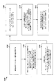
図10は、例示的な方法を示すブロック図(1000)である。eNBは、UE1に対してスケジュールされたストリーム-a(1002)およびUE2に対してスケジュールされたストリーム-b(1004)をリソースブロックのセットにマッピングする(1006)。第1の構成では、eNBは、ストリームをリソースブロックのセットにマッピングするために、UEにあらかじめ知られている所定のマッピングを使用し得る。第2の構成では、eNBは、データストリームを送信するための送信アンテナ(または送信アンテナの数)を選択するために、UEにあらかじめ知られている所定のマッピングを使用し得る。任意の特定のサブフレームに対して、所定のマッピングは、どのリソースブロック(たとえば、サブキャリア範囲)がデータストリームを搬送するかを指示し得る。所定のマッピングはまた、UEによってあらかじめ知られている所定の疑似ランダム位相回転の各々によって、どのリソース要素が調整されるかを指示し得る。eNBは、リソースブロックのセット内で変調され、位相回転されたデータシンボルをUE1に送信する。チャネル1008は、さらなる位相回転を送信に適用する。UEは、データ送信を受信し、データ送信をストリーム-aに対する受信フィルタを通して進行させる(1010)。受信フィルタは、MMSEフィルタ、最大比合成整合フィルタ、または別のタイプのフィルタとすることができる。フィルタは、サービングeNBおよび干渉eNBの各々によって使用される所定のマッピングと、サービングeNBおよび干渉eNBの各々によって適用される所定の疑似ランダム位相回転と、サービングeNBおよび干渉eNBの各々から受信されたパイロット信号および/または付加的に受信されたパイロット信号とを含む入力を有し得る。次に、UEは、フィルタリング済みデータストリームを復号する(1012)。
FIG. 10 is a block diagram (1000) illustrating an exemplary method. The eNB maps stream-a (1002) scheduled for UE 1 and stream-b (1004) scheduled for UE 2 to a set of resource blocks (1006). In the first configuration, the eNB may use a predetermined mapping that is known in advance by the UE to map the stream to a set of resource blocks. In the second configuration, the eNB may use a predetermined mapping that is known in advance to the UE to select a transmission antenna (or number of transmission antennas) for transmitting the data stream. For any particular subframe, the predetermined mapping may indicate which resource block (eg, subcarrier range) carries the data stream. The predetermined mapping may also indicate which resource elements are adjusted by each of the predetermined pseudo-random phase rotations known in advance by the UE. The eNB transmits data symbols modulated and phase rotated in the set of resource blocks to UE 1 .
図11Aは、第1の例示的な方法を示す図(1100)である。干渉の適時的整合と、データ送信との干渉不整合とを受信することになるサービングeNBからデータ送信のためのUEのセットを選択した後、サービングeNBは、UEのセットに対するデータストリームをリソースブロック1102、1104のセットにマッピングし得る。UEのセットが1つのUEを含むものと仮定する。通常、サービングeNBは、データストリームをリソースブロック1102だけにマッピングし得る。しかしながら、例示的な方法を使用して、サービングeNBは、データストリームをマッピングするための所定のマッピングを、リソースブロック1102の1つだけでなく、リソースブロック1102、1104の両方に適用する。データストリームをリソースブロック1102にマッピングすると、サービングeNBは、第1の所定の疑似ランダム位相回転1112を被変調データシンボルに適用する。データストリームをリソースブロック1104にマッピングすると、サービングeNBは、第2の所定の疑似ランダム位相回転1114を被変調データシンボルに適用する。次に、サービングeNBは、リソースブロック1102、1104内の被変調データシンボルをUEに送信する。この構成では、サービングeNBは、送信アンテナの各々において同じ線形マップを、異なる適用された位相回転を用いて反復することによって、ビームフォーミング/プリコーディングを実行し得る。UEは、それらのチャネルフィードバックにおいて複数のアンテナを有することの影響を含む。
FIG. 11A is a diagram (1100) illustrating a first exemplary method. After selecting a set of UEs for data transmission from the serving eNB that will receive timely alignment of interference and interference mismatch with data transmission, the serving eNB resource blocks the data stream for the set of UEs. 1102 and 1104 sets may be mapped. Assume that the set of UEs contains one UE. In general, the serving eNB may map the data stream only to the
この例では、所定のマッピングは、被変調データシンボルをリソースブロック1102からリソースブロック1104に複製することである。干渉eNBは、同じリソースブロック1102、1104内の同じ線形マッピングを適用する。干渉eNBの各々は、異なる所定の疑似ランダム位相回転をリソースブロック1102、1104内の被変調データシンボルに適用し得る。どの位相回転がサービングeNBおよび干渉eNBの各々によって適用されることになるかをUEがあらかじめ知っているので、適用される位相回転はあらかじめ決定されている。適用される位相回転は、サブフレーム数および/またはシステムフレーム数に基づき得る。適用される位相回転は疑似ランダムであり、それによって、干渉が、サービングeNBによってサービスされているUEのうちのいずれかに対するサービングeNBからのデータ送信と不整合でありながら、干渉eNBからの干渉の適時的整合を可能にするために、適用される位相回転が移り変わる。干渉の適時的整合およびデータ送信との干渉不整合は、チャネルフィードバックに基づいて決定される。線形マップはまた、時変であってよく、位相回転と異なる時間スケール上で変更されてよい。線形マップは、所定のシーケンスに依存することがある。
In this example, the predetermined mapping is to replicate the modulated data symbols from
図11Bは、第2の例示的な方法を示す図(1150)である。干渉の適時的整合と、データ送信との干渉不整合とを受信することになるサービングeNBからのデータ送信のためのUEのセットを選択した後、サービングeNBは、UEのセットに対するデータストリームをリソースブロック1152のセットにマッピングし得る。UEのセットが1つのUEを含むものと仮定する。通常行われるように、サービングeNBは、データストリームをリソースブロック1152だけにマッピングし得る。しかしながら、例示的な方法を使用して、サービングeNBは、リソースブロック1152内の被変調データシンボルを送信するための送信アンテナの数(または送信アンテナのセット)を選択するために、所定のマッピングを適用する。所定のマッピングがデータストリームを複製することである場合、サービングeNBは、MIMO送信において2つの送信アンテナ(各送信アンテナは複数のアンテナを含む)から被変調データシンボルを送信することを決定し得る。第1の送信アンテナからリソースブロック1152に対する被変調データシンボルを送信するとき、サービングeNBは、第1の位相回転1162を適用し得る。第2の送信アンテナからリソースブロック1152に対する同じ被変調データシンボルを送信するとき、サービングeNBは、第2の位相回転1172を適用し得る。
FIG. 11B is a diagram (1150) illustrating a second exemplary method. After selecting a set of UEs for data transmission from the serving eNB that will receive timely alignment of interference and interference mismatch with data transmission, the serving eNB resources the data stream for the set of UEs. Can map to a set of
この例では、所定のマッピングは、被変調データシンボルを複製することである。干渉eNBは同じ線形マッピングを適用し、それゆえ同じく、同じ数の送信アンテナを使用してリソースブロック1152上のデータ送信を送信する。どの位相回転が適用されることになるかをUEがあらかじめ知っているので、適用される位相回転はあらかじめ決定されている。適用される位相回転は、サブフレーム数および/またはシステムフレーム数に基づき得る。適用される位相回転は疑似ランダムであり、それによって干渉が、サービングeNBによってサービスされているUEのうちのいずれかに対するサービングeNBからのデータ送信と不整合でありながら、干渉eNBからの干渉の適時的整合を可能にするために、適用される位相回転が移り変わる。干渉の適時的整合およびデータ送信との干渉不整合は、チャネルフィードバックに基づいて決定される。
In this example, the predetermined mapping is to duplicate the modulated data symbol. The interfering eNB applies the same linear mapping and therefore also transmits data transmissions on
適時的干渉整合方式は、CDMAとともに適用されてもよく、そこにおいて、複数のUEが、直交コードまたはほぼ直交するコードを介して同じOFDMトーンを共有する。CDMAは、物理的サブキャリアの代わりに被変調ストリームのドメインにおいて適用され得る。受信機フィードバックは、これのために変更される必要はない。不均一な電力割り当て(固定された総電力を仮定する)が、UEを選択する間のeNBで発生することがある。1つのUEが、各変調方式に対応する各CDMAリソースに対して選択され得る。 A timely interference matching scheme may be applied with CDMA, in which multiple UEs share the same OFDM tone via orthogonal or nearly orthogonal codes. CDMA may be applied in the domain of the modulated stream instead of physical subcarriers. The receiver feedback need not be changed for this. Non-uniform power allocation (assuming a fixed total power) may occur at the eNB during UE selection. One UE may be selected for each CDMA resource corresponding to each modulation scheme.
I.数学的記述
干渉ネットワークに対する適時的干渉整合方式の数学的記述は、以下のとおりである。この方式の顕著な特徴は、明示的な送信機チャネル状態情報の必要性がないことである。代わりに、この方式は、受信機から関連する送信機へのチャネルフィードバック(たとえば、CQI、SINR、RSRP、RSRQ、RSSI)を使用する。このフィードバックは、複数の干渉送信機に対応する整合された干渉方向を用いて受信機を適時的にスケジュールするために使用される。任意の受信機における任意の干渉ストリームからの干渉方向は、送信機と受信機との間のチャネル行列と、そのストリームに対して送信機によって使用される方向ベクトルとの積である。チャネル行列がゆっくりと変化している場合、干渉方向は、送信機において使用される方向ベクトルに基づいて予測され得る。しかしながら、送信ビームフォーミングなどの伝統的方式では、方向ベクトルはフィードバックに基づいて時間的に変更され、したがって、干渉方向を予測することは困難である。干渉方向を予測することの難しさは、すべての受信機にあらかじめ知られている、送信機における所定のシーケンスの方向ベクトルを使用することによって克服される。送信機における所定の方向ベクトルを用いて、受信機は、適切な受信機結合技法(receiver combining technique)を介して干渉を軽減することを予想される。干渉軽減を実行するために、各受信機は、少なくとも2次元において信号と干渉とを受信する必要がある。受信機は、2つの周波数選択性リソースブロックまたはMIMOを使用することによって少なくとも2つの方向における信号を受信し得る。信号および干渉方向は知られているので、各受信機は、MMSEまたは最小干渉などの標準的な受信機結合技法を使用して受信機が取得し得るネットSINRを計算し得る。このSINRは、チャネルのコヒーレンス時間に応じて複数の将来のサブフレーム/スロットに対して決定され得る。関連する受信機からのSINRフィードバックは、スケジューリングのために各送信機によって使用される。スケジューリング決定は、各送信機によって単独で実行され得る。送信機は、プロポーショナルフェアスケジューリング(proportionally-fair scheduling)など、既存の技法を使用することによってスケジューリングに公平性を導入することができる。
I. Mathematical description The mathematical description of the timely interference matching scheme for the interference network is as follows. The salient feature of this scheme is that there is no need for explicit transmitter channel state information. Instead, this scheme uses channel feedback (eg, CQI, SINR, RSRP, RSRQ, RSSI) from the receiver to the associated transmitter. This feedback is used to schedule receivers in a timely manner with matched interference directions corresponding to multiple interfering transmitters. The interference direction from any interfering stream at any receiver is the product of the channel matrix between the transmitter and receiver and the direction vector used by the transmitter for that stream. If the channel matrix is changing slowly, the interference direction can be predicted based on the direction vector used at the transmitter. However, in traditional schemes such as transmit beamforming, the direction vector is changed in time based on feedback, and it is therefore difficult to predict the interference direction. The difficulty of predicting the direction of interference is overcome by using a predetermined sequence of direction vectors at the transmitter that is known in advance to all receivers. With a predetermined direction vector at the transmitter, the receiver is expected to mitigate interference through an appropriate receiver combining technique. In order to perform interference mitigation, each receiver needs to receive signals and interference in at least two dimensions. The receiver may receive signals in at least two directions by using two frequency selective resource blocks or MIMO. Since the signal and interference direction are known, each receiver may calculate a net SINR that the receiver can obtain using standard receiver combining techniques such as MMSE or minimum interference. This SINR may be determined for multiple future subframes / slots depending on the coherence time of the channel. SINR feedback from the associated receiver is used by each transmitter for scheduling. The scheduling decision can be performed independently by each transmitter. The transmitter can introduce fairness into the scheduling by using existing techniques such as proportionally-fair scheduling.
II.システムモデル
K-セルワイヤレスネットワークを考察する。あらゆるセルが、L個の関連する受信機を伴う単一の送信機を有する。各送信機によって使用される次元数をMとし、各受信機によって使用される次元数をNとする。送信機と受信機との間の準静的チャネルを考察する。離散時間、
![]()

![]()
![]()
Consider a K-cell wireless network. Every cell has a single transmitter with L associated receivers. Let M be the number of dimensions used by each transmitter, and N be the number of dimensions used by each receiver. Consider a quasi-static channel between a transmitter and a receiver. Discrete time,
![]()
![]()
![]()
III.適時的干渉整合
このセクションは、適時的干渉整合方式を説明する。任意の干渉ストリームに対応する任意の受信機における干渉方向は、送信機と受信機との間のチャネル行列と、そのストリームに対して送信機によって使用される方向ベクトルとの積である。したがって、干渉方向は、受信機がチャネル行列を推定し得る場合でかつ受信機が方向ベクトルを知っている場合に、受信機によって決定され得る。所定のシーケンスの方向ベクトルが送信機において使用され、それによって、受信機はこの知識を事前に取得し得る。
III. Timely Interference Matching This section describes timely interference matching schemes. The interference direction at any receiver corresponding to any interference stream is the product of the channel matrix between the transmitter and receiver and the direction vector used by the transmitter for that stream. Thus, the interference direction can be determined by the receiver when the receiver can estimate the channel matrix and when the receiver knows the direction vector. A predetermined sequence of direction vectors is used at the transmitter so that the receiver can obtain this knowledge in advance.
各送信機によって使用されるストリームの数を、S≦min{M、N}とする。j番目のセル内の送信機によって使用されるS方向ベクトルは、
![]()
xj[t]=Σsνj,s[t]qj,s[t] (2)
によって与えられ、ここでqj,sは、電力制約
![]()
x j [t] = Σ s ν j, s [t] q j, s [t] (2)
Where q j, s is the power constraint
i番目のセル内のl番目の受信機を考察する。受信されるベクトルは、
A.最小干渉
本題が干渉であることが与えられれば、対象とする方法はネット干渉を最小化する。したがって、このシナリオにおいて対象とする最適化問題は、
B.最大SINR
最適受信機は、そのストリームに対応するSINRを最大化する受信機である。したがって、このシナリオにおいて対象とする最適化問題は、
The optimum receiver is a receiver that maximizes SINR corresponding to the stream. Therefore, the optimization problem targeted in this scenario is
任意の受信機結合技法が与えられれば、各受信機は、受信機が将来のタイムスロットのために達成し得る各ストリームに対応するSINRを計算し得る。受信機は、チャネル推定と将来の方向ベクトルの知識とを使用する。次に、受信機は、このチャネルフィードバック情報をその関連する送信機に送信する。各送信機は、チャネルフィードバック情報を、各ストリームに対して1つの受信機をスケジュールするために使用する。スケジューリングは、プロポーショナルフェアネスなど、任意の公平性基準(fairness criterion)を使用して実行され得る。 Given any receiver combining technique, each receiver may calculate a SINR corresponding to each stream that the receiver can achieve for a future time slot. The receiver uses channel estimation and future direction vector knowledge. The receiver then transmits this channel feedback information to its associated transmitter. Each transmitter uses channel feedback information to schedule one receiver for each stream. Scheduling may be performed using any fairness criterion, such as proportional fairness.
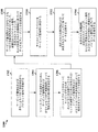
図12は、サービング基地局のワイヤレス通信の方法のフローチャート1200である。図12に示すように、ステップ1202で、サービング基地局は、パイロット信号を複数のUEに送信し得る。ステップ1204で、サービング基地局は、UEからチャネルフィードバックを受信する。チャネルフィードバックは、送信されたパイロット信号、サービング基地局で使用される所定のマッピング、およびサービング基地局で使用される所定の疑似ランダム位相回転に基づくことができる。同じく、チャネルフィードバックは、干渉基地局の各々で使用される所定の疑似ランダム位相回転に基づくことができる。ステップ1206で、サービング基地局は、受信されたチャネルフィードバックに基づいてデータ送信のためにUEのうちの少なくとも1つのUEを選択する。サービング基地局は、UEの各々からのチャネルフィードバックとしきい値とを比較し、チャネルフィードバックがしきい値より大きいことに基づいて少なくとも1つのUEの各々を選択し得る。サービング基地局は、この方式から最も利益を得るUEを選択し得る。この方式から最も利益を得るUEは、この方式がないと低いSINRを有するがこの方式によって十分に高いSINRを有するUEである。ステップ1208で、サービング基地局は、少なくとも1つのデータストリームをリソースブロックのセットにマッピングする。ステップ1210で、サービング基地局は、1つまたは複数の所定の疑似ランダム位相回転を、リソースブロックのセット内のデータを搬送するリソース要素内の被変調データシンボルに適用する。ステップ1212で、サービング基地局は、所定の位相回転に基づいて決定された位相回転を用いて、リソースブロックのセットを少なくとも1つのUEに送信する。
FIG. 12 is a
サービング基地局は、第1の所定の疑似ランダム位相回転をリソースブロックのセット内のリソース要素の第1のサブセットに適用し、第2の所定の疑似ランダム位相回転をリソースブロックのセット内のリソース要素の第2のサブセットに適用することができる。たとえば、図11Aを参照すると、サービング基地局は、第1の位相回転Θ1をリソースブロック1102内の被変調データシンボルに適用し、第2の位相回転Θ2をリソースブロック1104内の被変調データシンボルに適用することができる。サービング基地局は、異なる所定の疑似ランダム位相回転をリソースブロックのセットの複数のサブセットの各々に適用し得る。たとえば、Θ1はΘ2と等しくなくてもよい。所定の疑似ランダム位相回転は、サブフレームのセットにわたって異なる値に移り変わる/変化するので、サブフレームにおいてΘ1はΘ2に等しくてもよい。
The serving base station applies the first predetermined pseudo-random phase rotation to the first subset of resource elements in the set of resource blocks and the second predetermined pseudo-random phase rotation to the resource elements in the set of resource blocks Can be applied to the second subset of For example, referring to FIG. 11A, the serving base station applies the first phase rotation Θ 1 to the modulated data symbols in
所定のマッピングは、1つまたは複数のデータストリームをリソースブロックのセットにマッピングするために、サービング基地局によって使用される。一構成では、サービング基地局は、リソースブロックのセットにマッピングするときに、1つまたは複数のデータストリームに冗長性を加える。1つまたは複数のデータストリームは、通常、n個のリソースブロックにマッピングされる。しかしながら、サービング基地局は、1つまたは複数のデータストリームをm個のリソースブロックにマッピングし、ここでm>nである。したがって、第1の構成では、リソースブロックのセットはm個のリソースブロックを含む。所定のマッピングは、サブフレームのセットにわたって変化することがある。したがって、所定のマッピングのために使用されるサブキャリア、使用されるリソースブロックの数、および/または(たとえば、2つのリソースブロックを3つのリソースブロックにマッピングする、1つのリソースブロックを2つのリソースブロックにマッピング(複製)する)冗長性の量は、サブフレームの周期ごとに変化し得る。周期は、1つまたは複数のサブフレーム/フレームであってよい。 The predetermined mapping is used by the serving base station to map one or more data streams to a set of resource blocks. In one configuration, the serving base station adds redundancy to one or more data streams when mapping to a set of resource blocks. One or more data streams are typically mapped to n resource blocks. However, the serving base station maps one or more data streams to m resource blocks, where m> n. Therefore, in the first configuration, the set of resource blocks includes m resource blocks. The predetermined mapping may vary across the set of subframes. Thus, the subcarriers used for a given mapping, the number of resource blocks used, and / or (e.g., mapping one resource block to two resource blocks, mapping two resource blocks to three resource blocks The amount of redundancy that maps (duplicates) can vary from subframe period to subframe period. The period may be one or more subframes / frames.
第1の構成では、1つのリソースブロックが2つのリソースブロックにマッピングされ、それゆえ、被変調データシンボルが複製される。そのような構成では、m=2nである。被変調データシンボルが複製されるとき、データの半分だけが、リソースブロック内に送信され得る。しかしながら、複製されたデータは、2方向において電力利得を有するデータ送信をUEが受信することを可能にし、そのことは、上記で説明したように、データ送信からの整合された干渉またはほぼ整合された干渉をUEが消去することを可能にする。m=2nのとき、マッピングされたリソースブロックのセットは、同じOFDMシンボル上にn個のリソースブロックの第1のセットとn個のリソースブロックの第2のセットとを含み得る。リソースブロックの第2のセットは、リソースブロックの第1のセットとは異なる疑似ランダム位相回転を有し得る。サービング基地局は、所定のホッピング方式に基づいてm個のリソースブロックを選択し得る。サービング基地局は、データ送信を送信するためにビームフォーミングを使用し、送信アンテナからリソースブロックのセットの同時送信の各々に異なる位相回転を適用することができる。 In the first configuration, one resource block is mapped to two resource blocks, and thus the modulated data symbols are duplicated. In such a configuration, m = 2n. When the modulated data symbol is duplicated, only half of the data can be transmitted in the resource block. However, the replicated data allows the UE to receive a data transmission with power gain in two directions, which is matched interference or nearly matched from the data transmission as described above. Allows the UE to cancel the interference. When m = 2n, the set of mapped resource blocks may include a first set of n resource blocks and a second set of n resource blocks on the same OFDM symbol. The second set of resource blocks may have a different pseudorandom phase rotation than the first set of resource blocks. The serving base station may select m resource blocks based on a predetermined hopping scheme. The serving base station may use beamforming to transmit data transmissions and apply a different phase rotation to each of the simultaneous transmissions of the set of resource blocks from the transmit antenna.
第2の構成では、UEは、MIMOの使用を介して少なくとも2つの方向においてデータ送信を受信する。サービング基地局は、所定のマッピングに基づいて送信アンテナのセットを選択する。リソースブロックのセットは、所定の位相回転に基づく位相回転を用いて送信アンテナのセット内の各送信アンテナから送信される。たとえば、所定のマッピングがデータの複製を要求する場合、サービング基地局は、2つの異なる送信アンテナ(各送信アンテナはアンテナのセットである)を選択し、各送信アンテナを通して同時に、しかし各送信アンテナにおいて異なる所定の疑似ランダム位相回転を用いて、データ送信を送信することができる。リソースブロックのセットは、第1の所定の疑似ランダム位相回転を用いて第1の送信アンテナから、かつ第2の所定の疑似ランダム位相回転を用いて第2の送信アンテナから送信され得る。リソースブロックのセットは、異なる所定の疑似ランダム位相回転を用いて送信アンテナのセットの各送信アンテナから送信され得る。この構成では、チャネルフィードバックは、送信アンテナを選択するためにサービング基地局によって使用される所定のマッピングにさらに基づき得る。 In the second configuration, the UE receives data transmissions in at least two directions through the use of MIMO. The serving base station selects a set of transmit antennas based on a predetermined mapping. A set of resource blocks is transmitted from each transmit antenna in the set of transmit antennas using phase rotation based on a predetermined phase rotation. For example, if a given mapping requires data replication, the serving base station selects two different transmit antennas (each transmit antenna is a set of antennas) and simultaneously through each transmit antenna, but at each transmit antenna. Data transmissions can be transmitted using different predetermined pseudo-random phase rotations. The set of resource blocks may be transmitted from the first transmit antenna using a first predetermined pseudo-random phase rotation and from the second transmit antenna using a second predetermined pseudo-random phase rotation. A set of resource blocks may be transmitted from each transmit antenna of the set of transmit antennas using a different predetermined pseudo-random phase rotation. In this configuration, the channel feedback may be further based on a predetermined mapping used by the serving base station to select the transmit antenna.
図13は、UEのワイヤレス通信の方法のフローチャート1300である。図13に示すように、ステップ1302で、UEは、サービング基地局および少なくとも1つの干渉基地局からパイロット信号を受信する。ステップ1304で、UEは、リソースブロックを送信するためにサービング基地局および少なくとも1つの干渉基地局によって使用される位相回転を決定する。ステップ1306で、UEは、サービング基地局および少なくとも1つの干渉基地局によって使用されるマッピングを決定する。マッピングは、リソースブロックのセットにマッピングするため、および/または送信アンテナのセットを選択するために使用される。ステップ1308で、UEは、サービング基地局および少なくとも1つの干渉基地局の各々に対して、受信されたパイロット信号、決定されたマッピング、および決定された位相回転に基づいてチャネルフィードバックを決定する。ステップ1310で、UEは、チャネルフィードバックをサービング基地局に送信する。ステップ1312で、UEは、決定された位相回転および決定されたマッピングに基づいてデータを受信する。ステップ1314で、UEは、決定されたマッピング、決定された位相回転、および受信されたパイロット信号または付加的に受信されたパイロット信号のうちの少なくとも1つに基づいてデータを復号する。
FIG. 13 is a
第1の構成では、UEは、同じリソースブロックのセットにマッピングするために、サービング基地局および少なくとも1つの干渉基地局によって使用されるマッピングを決定し得る。UEは、リソースブロックをマッピングするためにサービング基地局および少なくとも1つの干渉基地局によって使用されるマッピングを示すマッピング情報をサービング基地局から受信し得る。代替として、サービング基地局および少なくとも1つの干渉基地局の各々に対するマッピングおよび/または位相回転は、基地局の識別子(すなわち、送信機識別子)、使用されるリソースブロックのサブキャリア、またはマッピングもしくは位相回転が適用されるサブフレーム数および/もしくはシステムフレーム数のうちの少なくとも1つに基づいて決定され得る。 In a first configuration, the UE may determine a mapping used by the serving base station and at least one interfering base station to map to the same set of resource blocks. The UE may receive mapping information from the serving base station indicating a mapping used by the serving base station and at least one interfering base station to map the resource block. Alternatively, the mapping and / or phase rotation for each of the serving base station and the at least one interfering base station is the base station identifier (i.e., transmitter identifier), the subcarrier of the resource block used, or the mapping or phase rotation. May be determined based on at least one of the number of subframes and / or the number of system frames.
第2の構成では、UEは、リソースブロックのセットを送信するための送信アンテナのセットを選択するために、サービング基地局および少なくとも1つの干渉基地局によって使用されるマッピングを決定し得る。送信アンテナのセット内の送信アンテナの数は、サービング基地局と少なくとも1つの干渉基地局の両方に対して同じであってよい。UEは、送信アンテナのセットを選択するためにサービング基地局および少なくとも1つの干渉基地局によって使用されるマッピングを示すマッピング情報をサービング基地局から受信し得る。代替として、サービング基地局および少なくとも1つの干渉基地局の各々に対するマッピングおよび/または位相回転は、基地局の識別子(すなわち、送信機識別子)、使用されるリソースブロックのサブキャリア、またはマッピングもしくは位相回転が適用されるサブフレーム数および/もしくはシステムフレーム数のうちの少なくとも1つに基づいて決定され得る。 In the second configuration, the UE may determine a mapping used by the serving base station and at least one interfering base station to select a set of transmit antennas for transmitting the set of resource blocks. The number of transmit antennas in the set of transmit antennas may be the same for both the serving base station and the at least one interfering base station. The UE may receive mapping information from the serving base station indicating a mapping used by the serving base station and at least one interfering base station to select a set of transmit antennas. Alternatively, the mapping and / or phase rotation for each of the serving base station and the at least one interfering base station is the base station identifier (i.e., transmitter identifier), the subcarrier of the resource block used, or the mapping or phase rotation. May be determined based on at least one of the number of subframes and / or the number of system frames.
上記で提供された適時的干渉整合方式は、電力利得と干渉低減とをスケジュールされたUEに与える。電力利得は、データの反復/複製によるものである。干渉低減は、干渉eNBからの干渉が整合またはほぼ整合されていながら、干渉eNBからの干渉と不整合であるサービングeNBからのデータ送信をUEが受信し得るように、eNBが異なる位相回転を適用することによるものである。特に、チャネル変動が時変でないかまたはゆっくりとした時変である場合、疑似ランダム位相回転は、適時的サービングeNBが利用してUE間に公平性をもたらすために、変動を導入する。UEは、UEによってあらかじめ知られている方式情報に基づいてチャネルフィードバックを提供する。eNBは、この方式がないと低いSINRを有するがこの方式によって十分に高いSINRを有するUEなど、この方式から最も利益を得るUEを選択し得る。 The timely interference matching scheme provided above provides a scheduled UE with power gain and interference reduction. The power gain is due to data repetition / replication. Interference reduction applies different phase rotations so that the UE can receive data transmission from the serving eNB that is inconsistent with the interference from the interference eNB, while the interference from the interference eNB is matched or nearly matched It is by doing. In particular, if the channel variation is not time-varying or slowly time-varying, the pseudo-random phase rotation introduces variation for the timely serving eNB to utilize to provide fairness among UEs. The UE provides channel feedback based on scheme information previously known by the UE. An eNB may select a UE that will benefit most from this scheme, such as a UE that has a low SINR without this scheme but has a sufficiently high SINR with this scheme.
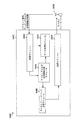
図14は、例示的な基地局装置1402における異なるモジュール/手段/構成要素間のデータフローを示す概念データフロー図1400である。装置1402は、UE1450からのチャネルフィードバックを含む複数のUEからのチャネルフィードバックを受信するように構成された受信モジュール1406を含む。チャネルフィードバックは、サービング基地局によって使用される所定の位相回転に基づく。チャネルフィードバックは、干渉基地局の各々によって使用される所定の位相回転にさらに基づくことができる。受信モジュール1406は、チャネルフィードバックをチャネルフィードバック分析モジュール1408に与えるように構成される。チャネルフィードバック分析モジュール1408は、チャネルフィードバックとしきい値とを比較することによるなど、チャネルフィードバックを比較するように構成される。チャネルフィードバック分析モジュール1408は、分析の結果をUE選択モジュール1410に伝達するように構成され、UE選択モジュール1410は、受信されたチャネルフィードバックに基づいてデータ送信のために、UEのうちの少なくとも1つのUEを選択するように構成される。UE選択モジュール1410は、その選択を、マッピングおよび位相回転適用モジュール1412に伝達するように構成される。マッピングおよび位相回転適用モジュール1412は、少なくとも1つのデータストリームをリソースブロックのセットにマッピングするように構成される。装置は、リソースブロックのセットを、所定の位相回転に基づいて決定された位相回転を用いて少なくとも1つのUEに送信するように構成された送信モジュール1404をさらに含む。送信モジュール1404は、パイロット信号をUE1450に送信するようにさらに構成されてもよく、同じく、UE1450がチャネルフィードバックを決定するためにこの情報を使用し得るように、マッピングおよび位相回転の情報をUE1450に送信するように構成され得る。
FIG. 14 is a conceptual data flow diagram 1400 illustrating a data flow between different modules / means / components in an exemplary
マッピングおよび位相回転適用モジュール1412は、第1の所定の疑似ランダム位相回転をリソースブロックのセット内のリソース要素の第1のサブセットに適用し、第2の所定の疑似ランダム位相回転をリソースブロックのセット内のリソース要素の第2のサブセットに適用するように構成され得る。マッピングおよび位相回転適用モジュール1412は、異なる所定の疑似ランダム位相回転をリソースブロックのセットの複数のサブセットの各々に適用するように構成され得る。所定の位相回転は、サブフレームのセットにわたって変化することがある。
The mapping and phase
第1の構成では、チャネルフィードバックは、少なくとも1つのデータストリームをリソースブロックのセットにマッピングするために、サービング基地局によって使用される所定のマッピングにさらに基づくことができる。同じリソースブロックのセット上の同じ所定のマッピングは、干渉基地局の各々によって使用される。第2の構成では、装置1402は、送信アンテナ選択モジュール1414をさらに含み、送信アンテナ選択モジュール1414は、所定のマッピングに基づいて送信アンテナのセットを選択するように構成される。そのような構成では、送信モジュール1404は、所定の位相回転に基づく位相回転を用いて送信アンテナのセット内の各送信アンテナからリソースブロックのセットを送信する。
In a first configuration, the channel feedback may be further based on a predetermined mapping used by the serving base station to map at least one data stream to a set of resource blocks. The same predetermined mapping on the same set of resource blocks is used by each of the interfering base stations. In the second configuration, the
装置は、図12の上記のフローチャートにおけるアルゴリズムのステップの各々を実行する追加のモジュールを含み得る。したがって、図12の上記のフローチャートにおける各ステップは、モジュールによって実行することができ、装置は、それらのモジュールのうちの1つまたは複数を含むことができる。モジュールは、特に、上記のプロセス/アルゴリズムを遂行するように構成されるか、上記のプロセス/アルゴリズムを実行するように構成されたプロセッサによって実施されるか、プロセッサによって実施するためにコンピュータ可読媒体内に記憶されるか、またはそれらのいくつかの組合せによる、1つまたは複数のハードウェア構成要素であってよい。 The apparatus may include additional modules that perform each of the algorithm steps in the above flow chart of FIG. Accordingly, each step in the above flowchart of FIG. 12 can be performed by modules, and the apparatus can include one or more of those modules. The module is specifically configured to perform the process / algorithm described above, implemented by a processor configured to execute the process / algorithm described above, or in a computer readable medium for execution by the processor. May be one or more hardware components, stored in or some combination thereof.
図15は、処理システム1514を使用する装置1402'のハードウェア実装の一例を示す図1500である。処理システム1514は、バス1524によって概略的に表されるバスアーキテクチャで実装され得る。バス1524は、処理システム1514の具体的な用途および全体的な設計制約に応じて、任意の数の相互接続するバスおよびブリッジを含み得る。バス1524は、プロセッサ1504によって表される1つまたは複数のプロセッサおよび/またはハードウェアモジュールと、モジュール1404、1406、1408、1410、1412、1414と、コンピュータ可読媒体1506とを含む様々な回路を互いにリンクさせる。バス1524は、タイミングソース、周辺機器、電圧調整器、および電力管理回路など、様々な他の回路をリンクさせることもでき、これらの回路は当技術分野でよく知られており、したがって、これ以上は説明しない。
FIG. 15 is a diagram 1500 illustrating an example of a hardware implementation of a
処理ユニット1514は、トランシーバ1510に結合され得る。トランシーバ1510は、1つまたは複数のアンテナ1520に結合される。トランシーバ1510は、送信媒体上の様々な他の装置と通信するための手段を提供する。トランシーバ1510は、1つまたは複数のアンテナ1520から信号を受信し、受信された信号から情報を抽出し、抽出された情報を処理システム1514、具体的には受信モジュール1406に与える。さらに、トランシーバ1510は、処理システム1514、具体的には送信モジュール1404から情報を受信し、受信された情報に基づいて、1つまたは複数のアンテナ1520に印加される信号を生成する。処理システム1514は、コンピュータ可読媒体1506に結合されたプロセッサ1504を含む。プロセッサ1504は、コンピュータ可読媒体1506上に記憶されたソフトウェアの実行を含む全般的な処理を受け持つ。ソフトウェアは、プロセッサ1504によって実行されると、任意の特定の装置に対して上記で説明した様々な機能を処理システム1514に実行させる。コンピュータ可読媒体1506は、ソフトウェアを実行するときにプロセッサ1504によって操作されるデータを記憶するために使用されてもよい。処理システムは、モジュール1404、1406、1408、1410、1412、1414のうちの少なくとも1つをさらに含む。モジュールは、コンピュータ可読媒体1506に常駐する/記憶される、プロセッサ1504で動作しているソフトウェアモジュール、プロセッサ1504に結合された1つもしくは複数のハードウェアモジュール、またはそれらの何らかの組合せとすることができる。処理システム1514は、eNB610の構成要素であってもよく、メモリ676、および/またはTXプロセッサ616、RXプロセッサ670、およびコントローラ/プロセッサ675のうちの少なくとも1つを含み得る。
一構成では、ワイヤレス通信のための装置1402/1402'は、複数のUEからチャネルフィードバックを受信するための手段を含む。チャネルフィードバックは、サービング基地局によって使用される所定の位相回転に基づく。装置は、受信されたチャネルフィードバックに基づいてデータ送信のためにUEのうちの少なくとも1つのUEを選択するための手段をさらに含む。装置は、少なくとも1つのデータストリームをリソースブロックのセットにマッピングするための手段をさらに含む。装置は、リソースブロックのセットを、所定の位相回転に基づいて決定された位相回転を用いて少なくとも1つのUEに送信するための手段をさらに含む。装置は、第1の所定の疑似ランダム位相回転をリソースブロックのセット内のリソース要素の第1のサブセットに適用し、第2の所定の疑似ランダム位相回転をリソースブロックのセット内のリソース要素の第2のサブセットに適用するための手段をさらに含み得る。装置は、異なる所定の疑似ランダム位相回転をリソースブロックのセットの複数のサブセットの各々に適用するための手段をさらに含み得る。所定の位相回転は、サブフレームのセットにわたって変化することがある。チャネルフィードバックは、少なくとも1つのデータストリームをリソースブロックのセットにマッピングするために、サービング基地局によって使用される所定のマッピングにさらに基づくことができる。少なくとも1つのデータストリームはn個のリソースブロックに対応し、mがnより大きい所定のマッピングに基づいてm個のリソースブロックにマッピングされ得る。リソースブロックのセットは、m個のリソースブロックを含み得る。所定のマッピングは、サブフレームのセットにわたって変化することがある。値mは2nに等しいことがある。マッピングされたリソースブロックのセットは、同じシンボル上にn個のリソースブロックの第1のセットとn個のリソースブロックの第2のセットとを含み得る。リソースブロックの第2のセットは、リソースブロックの第1のセットとは異なる疑似ランダム位相回転を有し得る。装置は、所定のホッピング方式に基づいてm個のリソースブロックを選択するための手段をさらに含み得る。装置は、UEの各々からのチャネルフィードバックとしきい値とを比較するための手段をさらに含み得る。少なくとも1つのUEの各々は、チャネルフィードバックがしきい値より大きいことに基づいて選択され得る。装置は、異なる位相回転を、送信アンテナからのリソースブロックのセットの同時送信の各々に適用するための手段をさらに含み得る。装置は、パイロット信号をUEに送信するための手段をさらに含んでもよく、チャネルフィードバックは、送信されたパイロット信号にさらに基づく。装置は、所定のマッピングに基づいて送信アンテナのセットを選択するための手段をさらに含み得る。リソースブロックのセットは、所定の位相回転に基づく位相回転を用いて送信アンテナのセット内の各送信アンテナから送信され得る。リソースブロックのセットは、第1の所定の疑似ランダム位相回転を用いて第1の送信アンテナから、かつ第2の所定の疑似ランダム位相回転を用いて第2の送信アンテナから送信され得る。リソースブロックのセットは、異なる所定の疑似ランダム位相回転を用いて送信アンテナのセットの各送信アンテナから送信され得る。チャネルフィードバックは、送信アンテナを選択するためにサービング基地局によって使用される所定のマッピングにさらに基づくことができる。
In one configuration, an
上記の手段は、装置1402の上記のモジュールおよび/または上記の手段によって記載された機能を実行するように構成された装置1402'の処理システム1514のうちの1つまたは複数であってよい。上記で説明したように、処理システム1514は、TXプロセッサ616、RXプロセッサ670、およびコントローラ/プロセッサ675を含み得る。したがって、一構成では、上記の手段は、TXプロセッサ616、RXプロセッサ670、および上記の手段によって記述される機能を実行するように構成されたコントローラ/プロセッサ675であってよい。
The means may be one or more of the above modules of the
図16は、例示的なUE装置1602における異なるモジュール/手段/構成要素間のデータフローを示す概念データフロー図1600である。装置1602は、サービング基地局1650および少なくとも1つの干渉基地局からパイロット信号を受信するように構成された受信モジュール1604を含む。受信モジュール1604は、マッピングおよび位相回転の情報を受信するようにさらに構成され得る。マッピングおよび位相回転の情報は、リソースブロックのセットにマッピングするためにサービング基地局1650および少なくとも1つの干渉基地局によって使用されるマッピングを含み、サービングeNBおよび少なくとも1つの干渉基地局によってリソースブロックのセット内の被変調データシンボルに適用される位相回転を含む。装置1602は、マッピングおよび位相回転決定モジュール1606をさらに含み、マッピングおよび位相回転決定モジュール1606は、リソースブロックを送信するためにサービング基地局および少なくとも1つの干渉基地局によって使用される位相回転を決定するように構成される。装置1602は、サービング基地局および少なくとも1つの干渉基地局の各々に対して、受信されたパイロット信号、決定されたマッピング、および決定された位相回転に基づいてチャネルフィードバックを決定するように構成された、チャネルフィードバック決定モジュール1608をさらに含む。装置1602は、チャネルフィードバックをサービング基地局1650に送信するように構成された送信モジュールをさらに含む。受信モジュール1604は、決定された位相回転に基づいてデータ送信を受信し、受信されたデータ送信をデータ処理モジュール1612に与えるように構成される。データ処理モジュール1612は、フィルタ、決定されたマッピングおよび位相回転の情報、ならびにパイロット信号および/または付加的に受信されたパイロット信号に基づいてデータを復号するように構成される。
FIG. 16 is a conceptual data flow diagram 1600 illustrating the data flow between different modules / means / components in
マッピングおよび位相回転決定モジュール1606は、リソースブロックをマッピングするためにサービング基地局および少なくとも1つの干渉基地局によって使用されるマッピングを決定するように構成され得る。サービング基地局1650および少なくとも1つの干渉基地局によるマッピングは、同じリソースブロックのセットに対するものである。一構成では、装置1602は、サービング基地局1650および少なくとも1つの干渉基地局によって使用されるマッピングを示す明示的な情報を受信する。別の構成では、装置1602は、サービング基地局1650および少なくとも1つの干渉基地局によって使用されるマッピングを決定する。装置1602は、送信機識別子、サブキャリア、またはサブフレームに基づいてマッピングを決定し得る。
The mapping and phase
マッピングおよび位相回転決定モジュール1606は、リソースブロックのセットを送信するための送信アンテナのセットを選択するために、サービング基地局および少なくとも1つの干渉基地局によって使用されるマッピングを決定し得る。送信アンテナのセット内の送信アンテナの数は、サービング基地局と少なくとも1つの干渉基地局の両方に対して同じであってよい。一構成では、装置1602は、サービング基地局1650および少なくとも1つの干渉基地局によって使用されるマッピングを示す明示的な情報を受信する。別の構成では、装置1602は、サービング基地局1650および少なくとも1つの干渉基地局によって使用されるマッピングを決定する。装置1602は、送信機識別子、サブキャリア、またはサブフレームに基づいてマッピングを決定し得る。
The mapping and phase
装置は、図13の上記のフローチャートにおけるアルゴリズムのステップの各々を実行する追加のモジュールを含み得る。したがって、図13の上記のフローチャートにおける各ステップは、モジュールによって実行することができ、装置は、それらのモジュールのうちの1つまたは複数を含むことができる。モジュールは、特に、上記のプロセッサ/アルゴリズムを遂行するように構成されるか、上記のプロセッサ/アルゴリズムを実行するように構成されたプロセッサによって実施されるか、プロセッサによって実施するためにコンピュータ可読媒体内に記憶されるか、またはそれらのいくつかの組合せによる、1つまたは複数のハードウェア構成要素であってよい。 The apparatus may include additional modules that perform each of the algorithm steps in the above flow chart of FIG. Thus, each step in the above flowchart of FIG. 13 can be performed by modules, and the device can include one or more of those modules. The module is specifically configured to perform the processor / algorithm described above, implemented by a processor configured to execute the processor / algorithm described above, or in a computer readable medium for execution by the processor. May be one or more hardware components, stored in or some combination thereof.
図17は、処理システム1714を使用するUE装置1602'のハードウェア実装の一例を示す図1700である。処理システム1714は、バス1724によって概略的に表されるバスアーキテクチャで実装され得る。バス1724は、処理システム1714の具体的な用途および全体的な設計制約に応じて、任意の数の相互接続するバスおよびブリッジを含み得る。バス1724は、プロセッサ1704によって表される1つまたは複数のプロセッサおよび/またはハードウェアモジュールと、モジュール1604、1606、1608、1610、1612と、コンピュータ可読媒体1706とを含む様々な回路を互いにリンクさせる。バス1724は、タイミングソース、周辺機器、電圧調整器、および電力管理回路など、様々な他の回路をリンクさせることもでき、これらの回路は当技術分野でよく知られており、したがって、これ以上は説明しない。
FIG. 17 is a diagram 1700 illustrating an example of a hardware implementation of a
処理ユニット1714は、トランシーバ1710に結合され得る。トランシーバ1710は、1つまたは複数のアンテナ1720に結合される。トランシーバ1710は、送信媒体上の様々な他の装置と通信するための手段を提供する。トランシーバ1710は、1つまたは複数のアンテナ1720から信号を受信し、受信された信号から情報を抽出し、抽出された情報を処理システム1714、具体的には受信モジュール1604に与える。さらに、トランシーバ1710は、処理システム1714、具体的には送信モジュール1610から情報を受信し、受信された情報に基づいて、1つまたは複数のアンテナ1720に印加される信号を生成する。処理システム1714は、コンピュータ可読媒体1706に結合されたプロセッサ1704を含む。プロセッサ1704は、コンピュータ可読媒体1706上に記憶されたソフトウェアの実行を含む全般的な処理を受け持つ。ソフトウェアは、プロセッサ1704によって実行されると、任意の特定の装置に対して上記で説明した様々な機能を処理システム1714に実行させる。コンピュータ可読媒体1706は、ソフトウェアを実行するときにプロセッサ1704によって操作されるデータを記憶するために使用されてもよい。処理システムは、モジュール1604、1606、1608、1610、1612のうちの少なくとも1つをさらに含む。モジュールは、コンピュータ可読媒体1706に常駐する/記憶される、プロセッサ1704で動作しているソフトウェアモジュール、プロセッサ1704に結合された1つもしくは複数のハードウェアモジュール、またはそれらの何らかの組合せとすることができる。処理システム1714は、UE650の構成要素であってよく、メモリ660ならびに/あるいはTXプロセッサ668、RXプロセッサ656、およびコントローラ/プロセッサ659のうちの少なくとも1つを含み得る。
一構成では、ワイヤレス通信のための装置1602/1602'は、サービング基地局および少なくとも1つの干渉基地局からパイロット信号を受信するための手段と、リソースブロックを送信するためにサービング基地局および少なくとも1つの干渉基地局によって使用される位相回転を決定するための手段と、サービング基地局および少なくとも1つの干渉基地局の各々に対して受信されたパイロット信号および決定された位相回転に基づいてチャネルフィードバックを決定するための手段と、チャネルフィードバックをサービング基地局に送信するための手段と、決定された位相回転に基づいてデータを受信するための手段とを含む。装置は、リソースブロックをマッピングするためにサービング基地局および少なくとも1つの干渉基地局によって使用されるマッピングを決定するための手段をさらに含み得る。サービング基地局および少なくとも1つの干渉基地局によるマッピングは、同じリソースブロックのセットに対するものであってよい。チャネルフィードバックは、決定されたマッピングにさらに基づくことができ、データは、決定されたマッピングに基づいてリソースブロックのセット上で受信される。装置は、決定されたマッピング、決定された位相回転、および受信されたパイロット信号または追加で受信されたパイロット信号のうちの少なくとも1つに基づいてデータを復号するための手段をさらに含み得る。装置は、リソースブロックをマッピングするためにサービング基地局および少なくとも1つの干渉基地局によって使用されるマッピングを示すマッピング情報をサービング基地局から受信するための手段をさらに含み得る。サービング基地局および少なくとも1つの干渉基地局の各々に対するマッピングまたは位相回転のうちの少なくとも1つが、送信機識別子、サブキャリア、またはサブフレームのうちの少なくとも1つに基づいて決定され得る。装置は、リソースブロックのセットを送信するための送信アンテナのセットを選択するために、サービング基地局および少なくとも1つの干渉基地局によって使用されるマッピングを決定するための手段をさらに含み得る。送信アンテナのセット内の送信アンテナの数は、サービング基地局と少なくとも1つの干渉基地局の両方に対して同じであってよい。チャネルフィードバックは、決定されたマッピングにさらに基づくことができ、データは、決定されたマッピングに基づいてリソースブロックのセット上で受信される。装置は、決定されたマッピング、決定された位相回転、および受信されたパイロット信号または付加的に受信されたパイロット信号のうちの少なくとも1つに基づいてデータを復号するための手段をさらに含み得る。装置は、送信アンテナのセットを選択するためにサービング基地局および少なくとも1つの干渉基地局によって使用されるマッピングを示すマッピング情報をサービング基地局から受信するための手段をさらに含み得る。サービング基地局および少なくとも1つの干渉基地局の各々に対するマッピングまたは位相回転のうちの少なくとも1つが、送信機識別子、サブキャリア、またはサブフレームのうちの少なくとも1つに基づいて決定され得る。サービング基地局に対して決定された位相回転は、少なくとも1つの干渉基地局に対して決定された位相回転と異なってもよい。
In one configuration, an
上記の手段は、装置1602の上記のモジュールおよび/または上記の手段によって記述される機能を実行するように構成された装置1602'の処理システム1714のうちの1つまたは複数であってよい。上記で説明したように、処理システム1714は、TXプロセッサ668、RXプロセッサ656、およびコントローラ/プロセッサ659を含み得る。したがって、一構成では、上記の手段は、TXプロセッサ668、RXプロセッサ656、および上記の手段によって記述される機能を実行するように構成されたコントローラ/プロセッサ659であってよい。
The means may be one or more of the
開示したプロセスにおけるステップの特定の順序または階層は、例示的な手法の一例であることを理解されたい。設計上の選好に基づいて、プロセスにおけるステップの特定の順序または階層は再構成可能であることを理解されたい。さらに、いくつかのステップが、組み合わされ得るかまたは省略され得る。添付の方法クレームは、様々なステップの要素を例示的な順序で提示したものであり、提示された特定の順序または階層に限定されるものではない。 It is to be understood that the specific order or hierarchy of steps in the processes disclosed is an example of an exemplary approach. It should be understood that a particular order or hierarchy of steps in the process can be reconfigured based on design preferences. In addition, some steps may be combined or omitted. The accompanying method claims present elements of the various steps in a sample order, and are not limited to the specific order or hierarchy presented.
上記の説明は、本明細書で説明される様々な態様を当業者が実施できるようにするために与えられる。これらの態様への様々な変更は当業者には容易に明らかであり、本明細書で定義した一般的原理は他の態様に適用され得る。したがって、特許請求の範囲は本明細書で示す態様に限定されるよう意図されているわけではなく、文言通りの特許請求の範囲と整合するすべての範囲を許容するように意図されており、単数の要素への言及は、そのように明記されていない限り、「唯一無二の」ではなく、「1つまたは複数の」を意味するよう意図されている。別段に明記されていない限り、「いくつかの」という用語は「1つまたは複数の」を意味する。当業者に知られている、または後で知られることになる本開示全体にわたって説明する様々な態様の要素に対するすべての構造的および機能的均等物は、参照により本明細書に明確に組み込まれ、特許請求の範囲によって包含されるものとする。さらに、本明細書で開示する内容は、そのような開示が特許請求の範囲で明示的に記載されているかどうかにかかわらず、公に供することは意図されていない。いかなるクレーム要素も、要素が「ための手段(means for)」という語句を使用して明確に記載されていない限り、ミーンズプラスファンクションとして解釈されるべきではない。 The above description is provided to enable any person skilled in the art to implement various aspects described herein. Various modifications to these aspects will be readily apparent to those skilled in the art, and the generic principles defined herein may be applied to other aspects. Accordingly, the claims are not intended to be limited to the embodiments shown herein, but are intended to allow the full scope to be consistent with the literal claims. References to elements in are intended to mean “one or more”, not “one and only”, unless explicitly stated otherwise. Unless otherwise specified, the term “several” means “one or more”. All structural and functional equivalents to the elements of the various aspects described throughout this disclosure that are known to those skilled in the art or later become known are expressly incorporated herein by reference, It is intended to be encompassed by the claims. Furthermore, the content disclosed herein is not intended to be publicly available regardless of whether such disclosure is expressly recited in the claims. No claim element should be construed as a means plus function unless the element is expressly stated using the phrase “means for”.
100 LTEネットワークアーキテクチャ、発展型パケットシステム(EPS)
102 ユーザ機器(UE)
104 発展型UMTS地上波無線アクセスネットワーク(E-UTRAN)
106 発展型ノードB(eNB)
108 他のeNB
110 発展型パケットコア(EPC)
112 モビリティ管理エンティティ(MME)
114 他のMME
116 サービングゲートウェイ
118 パケットデータネットワーク(PDN)ゲートウェイ
120 ホーム加入者サーバ(HSS)
122 事業者のIPサービス
200 アクセスネットワーク
202 セル
204 マクロeNB
206 UE
208 低い電力クラスのeNB
210 セルラー領域
300 LTEにおけるDLフレーム構造の一例を示す図
302 セル固有RS(CRS)
304 UE固有RS(UE-RS)
400 LTEにおけるULフレーム構造の一例を示す図
410a リソースブロック
410b リソースブロック
420a リソースブロック
420b リソースブロック
430 物理ランダムアクセスチャネル(PRACH)
500 LTEにおけるユーザプレーンおよび制御プレーンの無線プロトコルアーキテクチャの一例を示す図
506 物理層
508 L2層
510 メディアアクセス制御(MAC)副層
512 無線リンク制御(RLC)副層
514 パケットデータコンバージェンスプロトコル(PDCP)副層
516 無線リソース制御(RRC)副層
610 eNB
616 送信(TX)プロセッサ
618TX 送信機
618RX 受信機
620 アンテナ
650 UE
652 アンテナ
654TX 送信機
654RX 受信機
656 受信(RX)プロセッサ
658 チャネル推定器
659 コントローラ/プロセッサ
660 メモリ
662 データシンク
667 データソース
668 TXプロセッサ
670 RXプロセッサ
674 チャネル推定器
675 コントローラ/プロセッサ
676 メモリ
700 第1の図
702 パイロット信号
704 データ送信
708 チャネルフィードバック
710 チャネルフィードバック
712 チャネルフィードバック
714 パイロット信号
716 パイロット信号
720 サービングeNB
730 干渉eNB
734 データ送信
740 干渉eNB
744 データ送信
750 UE
760 UE
770 UE
780 UE
790 UE
800 図
850 図
900 第3の図
902 eNB
904 eNB
906 eNB
908 UE
910 UE
912 UE
920 方向矢印
930 方向矢印
942 データ送信
944 データ送信
946 データ送信
1000 ブロック図
1002 UE1に対してスケジュールされたストリーム-a
1004 UE2に対してスケジュールされたストリーム-b
1006 UE1に対してスケジュールされたストリーム-aおよびUE2に対してスケジュールされたストリーム-bをリソースブロックのセットにマッピングする
1008 チャネル
1010 UEは、データ送信を受信し、データ送信をストリーム-aに対する受信フィルタを通して進行させる
1100 図
1102 リソースブロック
1104 リソースブロック
1112 第1の所定の疑似ランダム位相回転
1114 第2の所定の疑似ランダム位相回転
1150 図
1152 リソースブロック
1162 第1の位相回転
1172 第2の位相回転
1400 概念データフロー図
1402 基地局装置
1402' 基地局装置
1404 送信モジュール
1406 受信モジュール
1408 チャネルフィードバック分析モジュール
1410 UE選択モジュール
1412 マッピングおよび位相回転適用モジュール
1414 送信アンテナ選択モジュール
1450 UE
1500 ハードウェア実装の一例を示す図
1504 プロセッサ
1506 コンピュータ可読媒体
1510 トランシーバ
1514 処理システム
1520 アンテナ
1524 バス
1600 概念データフロー図
1602 UE装置
1604 受信モジュール
1606 マッピングおよび位相回転決定モジュール
1608 チャネルフィードバック決定モジュール
1610 送信モジュール
1612 データ処理モジュール
1650 サービング基地局
1700 ハードウェア実装の一例を示す図
1704 プロセッサ
1706 コンピュータ可読媒体
1710 トランシーバ
1714 処理システム
1720 アンテナ
1724 バス
100 LTE network architecture, advanced packet system (EPS)
102 User equipment (UE)
104 Advanced UMTS Terrestrial Radio Access Network (E-UTRAN)
106 Evolved Node B (eNB)
108 other eNB
110 Advanced Packet Core (EPC)
112 Mobility Management Entity (MME)
114 Other MMEs
116 Serving gateway
118 Packet Data Network (PDN) Gateway
120 Home Subscriber Server (HSS)
122 Provider IP services
200 access network
202 cells
204 Macro eNB
206 UE
208 low power class eNB
210 Cellular area
Diagram showing an example of DL frame structure in 300 LTE
302 Cell-specific RS (CRS)
304 UE-specific RS (UE-RS)
Diagram showing an example of UL frame structure in 400 LTE
410a Resource block
410b Resource block
420a resource block
420b resource block
430 Physical Random Access Channel (PRACH)
A diagram showing an example of radio protocol architecture of user plane and control plane in 500 LTE
506 Physical layer
508 L2 layer
510 Media Access Control (MAC) sublayer
512 Radio Link Control (RLC) sublayer
514 Packet Data Convergence Protocol (PDCP) sublayer
516 Radio Resource Control (RRC) sublayer
610 eNB
616 Transmit (TX) processor
618TX transmitter
618RX receiver
620 antenna
650 UE
652 Antenna
654TX transmitter
654RX receiver
656 Receive (RX) processor
658 channel estimator
659 Controller / Processor
660 memory
662 Data Sync
667 data sources
668 TX processor
670 RX processor
674 channel estimator
675 Controller / Processor
676 memory
700 Figure 1
702 Pilot signal
704 Data transmission
708 channel feedback
710 channel feedback
712 channel feedback
714 Pilot signal
716 Pilot signal
720 Serving eNB
730 Interference eNB
734 Data transmission
740 Interference eNB
744 Data transmission
750 UE
760 UE
770 UE
780 UE
790 UE
800 Figure
850 fig
900 Figure 3
902 eNB
904 eNB
906 eNB
908 UE
910 UE
912 UE
920 direction arrow
930 direction arrow
942 Data transmission
944 Data transmission
946 Data transmission
1000 block diagram
1002 Scheduled stream for UE 1 -a
1004 stream-b scheduled for UE 2
1006 Map stream-a scheduled for UE 1 and stream-b scheduled for UE 2 to a set of resource blocks
1008 channels
1010 UE receives data transmission and proceeds data transmission through receive filter for stream-a
1100 fig
1102 Resource block
1104 Resource block
1112 First predetermined pseudo-random phase rotation
1114 Second predetermined pseudo-random phase rotation
1150 fig
1152 Resource block
1162 First phase rotation
1172 Second phase rotation
1400 Conceptual data flow diagram
1402 Base station equipment
1402 'Base station equipment
1404 Transmitter module
1406 Receiver module
1408 Channel feedback analysis module
1410 UE selection module
1412 Mapping and phase rotation application module
1414 Transmit antenna selection module
1450 UE
Figure showing an example of 1500 hardware implementation
1504 processor
1506 Computer-readable media
1510 transceiver
1514 Processing system
1520 antenna
1524 bus
1600 Conceptual data flow diagram
1602 UE equipment
1604 Receiver module
1606 Mapping and phase rotation determination module
1608 channel feedback decision module
1610 transmitter module
1612 Data processing module
1650 serving base station
Diagram showing an example of 1700 hardware implementation
1704 processor
1706 Computer-readable media
1710 transceiver
1714 Processing system
1720 antenna
1724 Bus
Claims (34)
チャネルフィードバックを複数のユーザ機器(UE)から受信するステップであって、前記チャネルフィードバックは、前記サービング基地局と少なくとも1つの干渉基地局とによって使用される1つまたは複数の所定の位相回転に基づき、前記1つまたは複数の所定の位相回転は、前記複数のユーザ機器にあらかじめ知られている、ステップと、
前記受信されたチャネルフィードバックに基づいてデータ送信のために前記UEのうちの少なくとも1つのUEを選択するステップと、
少なくとも1つのデータストリームをリソースブロックのセットにマッピングするステップと、
第1の所定の疑似ランダム位相回転をリソースブロックの前記セット内のリソース要素の第1のサブセットに適用し、かつ第2の所定の疑似ランダム位相回転をリソースブロックの前記セット内のリソース要素の第2のサブセットに適用することにより、前記1つまたは複数の所定の位相回転に基づいて決定された位相回転を用いて、リソースブロックの前記セットを前記少なくとも1つのUEに送信するステップと
を含む、方法。 A wireless communication method for a serving base station,
Receiving channel feedback from a plurality of user equipments (UEs), wherein the channel feedback is based on one or more predetermined phase rotations used by the serving base station and at least one interfering base station. The one or more predetermined phase rotations are known in advance to the plurality of user equipments;
Selecting at least one of the UEs for data transmission based on the received channel feedback;
Mapping at least one data stream to a set of resource blocks;
Applying a first predetermined pseudo-random phase rotation to a first subset of resource elements in the set of resource blocks, and applying a second predetermined pseudo-random phase rotation of the resource elements in the set of resource blocks. Transmitting the set of resource blocks to the at least one UE using a phase rotation determined based on the one or more predetermined phase rotations by applying to a subset of two. Method.
チャネルフィードバックを複数のユーザ機器(UE)から受信するステップであって、前記チャネルフィードバックは、前記サービング基地局によって使用される1つまたは複数の所定の位相回転に基づき、前記1つまたは複数の所定の位相回転は、前記複数のユーザ機器にあらかじめ知られている、ステップと、
前記受信されたチャネルフィードバックに基づいてデータ送信のために前記UEのうちの少なくとも1つのUEを選択するステップと、
少なくとも1つのデータストリームをリソースブロックのセットにマッピングするステップと、
前記1つまたは複数の所定の位相回転に基づいて決定された位相回転を用いて、リソースブロックの前記セットを前記少なくとも1つのUEに送信するステップであって、前記サービング基地局によって使用される所定のマッピングが、前記チャネルフィードバックに基づいて前記少なくとも1つのデータストリームをリソースブロックの前記セットにマッピングするために使用され、前記所定のマッピングが、サブフレームのセットにわたって変化し、前記少なくとも1つのデータストリームがn個のリソースブロックに対応し、かつ前記所定のマッピングに基づいてm個のリソースブロックにマッピングされ、mがnより大きく、リソースブロックの前記セットが前記m個のリソースブロックを含む、ステップと
を含む、方法。 A wireless communication method for a serving base station,
Receiving channel feedback from a plurality of user equipments (UEs), wherein the channel feedback is based on one or more predetermined phase rotations used by the serving base station. The phase rotation of is known in advance to the plurality of user equipments, and
Selecting at least one of the UEs for data transmission based on the received channel feedback;
Mapping at least one data stream to a set of resource blocks;
Transmitting the set of resource blocks to the at least one UE using a phase rotation determined based on the one or more predetermined phase rotations, the predetermined used by the serving base station Mapping is used to map the at least one data stream to the set of resource blocks based on the channel feedback, the predetermined mapping varies over a set of subframes, and the at least one data stream Corresponds to n resource blocks and is mapped to m resource blocks based on the predetermined mapping, m is greater than n, and the set of resource blocks includes the m resource blocks; and Including a method.
チャネルフィードバックを複数のユーザ機器(UE)から受信するステップであって、前記チャネルフィードバックは、前記サービング基地局によって使用される1つまたは複数の所定の位相回転に基づき、前記1つまたは複数の所定の位相回転は、前記複数のユーザ機器にあらかじめ知られている、ステップと、
前記受信されたチャネルフィードバックに基づいてデータ送信のために前記UEのうちの少なくとも1つのUEを選択するステップと、
少なくとも1つのデータストリームをリソースブロックのセットにマッピングするステップと、
所定のマッピングに基づいて送信アンテナのセットを選択するステップと、
前記1つまたは複数の所定の位相回転に基づいて決定された位相回転を用いて前記少なくとも1つのUEにリソースブロックの前記セットを送信するステップであって、リソースブロックの前記セットは、第1の所定の疑似ランダム位相回転を用いて第1の送信アンテナから送信され、かつ第2の所定の疑似ランダム位相回転を用いて第2の送信アンテナから送信される、ステップと
を含む、方法。 A wireless communication method for a serving base station,
Receiving channel feedback from a plurality of user equipments (UEs), wherein the channel feedback is based on one or more predetermined phase rotations used by the serving base station. The phase rotation of is known in advance to the plurality of user equipments, and
Selecting at least one of the UEs for data transmission based on the received channel feedback;
Mapping at least one data stream to a set of resource blocks;
Selecting a set of transmit antennas based on a predetermined mapping;
Transmitting the set of resource blocks to the at least one UE using a phase rotation determined based on the one or more predetermined phase rotations, the set of resource blocks comprising: Transmitted from the first transmit antenna using a predetermined pseudo-random phase rotation and transmitted from the second transmit antenna using a second predetermined pseudo-random phase rotation.
チャネルフィードバックを、複数のユーザ機器(UE)から受信するための手段であって、前記チャネルフィードバックは、前記サービング基地局と少なくとも1つの干渉基地局とによって使用される1つまたは複数の所定の位相回転に基づき、前記1つまたは複数の所定の位相回転は、前記複数のユーザ機器にあらかじめ知られている、手段と、
前記受信されたチャネルフィードバックに基づいてデータ送信のために前記UEのうちの少なくとも1つのUEを選択するための手段と、
少なくとも1つのデータストリームをリソースブロックのセットにマッピングするための手段と、
第1の所定の疑似ランダム位相回転をリソースブロックの前記セット内のリソース要素の第1のサブセットに適用し、かつ第2の所定の疑似ランダム位相回転をリソースブロックの前記セット内のリソース要素の第2のサブセットに適用することにより、前記1つまたは複数の所定の位相回転に基づいて決定された位相回転を用いて、リソースブロックの前記セットを前記少なくとも1つのUEに送信するための手段と
を含む、サービング基地局。 A serving base station for wireless communication,
Means for receiving channel feedback from a plurality of user equipments (UEs), wherein the channel feedback is one or more predetermined phases used by the serving base station and at least one interfering base station. Based on rotation, the one or more predetermined phase rotations are known in advance to the plurality of user equipments; and
Means for selecting at least one of the UEs for data transmission based on the received channel feedback;
Means for mapping at least one data stream to a set of resource blocks;
Applying a first predetermined pseudo-random phase rotation to a first subset of resource elements in the set of resource blocks, and applying a second predetermined pseudo-random phase rotation of the resource elements in the set of resource blocks. Means for transmitting the set of resource blocks to the at least one UE using a phase rotation determined based on the one or more predetermined phase rotations by applying to a subset of two. Including serving base station.
チャネルフィードバックを複数のユーザ機器(UE)から受信するための手段であって、前記チャネルフィードバックは、前記サービング基地局によって使用される1つまたは複数の所定の位相回転に基づき、前記1つまたは複数の所定の位相回転は、前記複数のユーザ機器にあらかじめ知られている、手段と、
前記受信されたチャネルフィードバックに基づいてデータ送信のために前記UEのうちの少なくとも1つのUEを選択するための手段と、
少なくとも1つのデータストリームをリソースブロックのセットにマッピングするための手段と、
前記1つまたは複数の所定の位相回転に基づいて決定された位相回転を用いて、リソースブロックの前記セットを前記少なくとも1つのUEに送信するための手段であって、前記サービング基地局によって使用される所定のマッピングが、前記チャネルフィードバックに基づいて前記少なくとも1つのデータストリームをリソースブロックの前記セットにマッピングするために使用され、前記所定のマッピングが、サブフレームのセットにわたって変化し、前記少なくとも1つのデータストリームがn個のリソースブロックに対応し、かつ前記所定のマッピングに基づいてm個のリソースブロックにマッピングされ、mがnより大きく、リソースブロックの前記セットが前記m個のリソースブロックを含む、手段と
を備える、サービング基地局。 A serving base station for wireless communication,
Means for receiving channel feedback from a plurality of user equipments (UEs), wherein the channel feedback is based on one or more predetermined phase rotations used by the serving base station. A predetermined phase rotation of the plurality of user equipments known in advance;
Means for selecting at least one of the UEs for data transmission based on the received channel feedback;
Means for mapping at least one data stream to a set of resource blocks;
Means for transmitting the set of resource blocks to the at least one UE using a phase rotation determined based on the one or more predetermined phase rotations, used by the serving base station. A predetermined mapping is used to map the at least one data stream to the set of resource blocks based on the channel feedback, the predetermined mapping varies across the set of subframes, and the at least one A data stream corresponds to n resource blocks and is mapped to m resource blocks based on the predetermined mapping, where m is greater than n and the set of resource blocks includes the m resource blocks; And a serving base station.
チャネルフィードバックを複数のユーザ機器(UE)から受信するための手段であって、前記チャネルフィードバックは、前記サービング基地局によって使用される1つまたは複数の所定の位相回転に基づき、前記1つまたは複数の所定の位相回転は、前記複数のユーザ機器にあらかじめ知られている、手段と、
前記受信されたチャネルフィードバックに基づいてデータ送信のために前記UEのうちの少なくとも1つのUEを選択するための手段と、
少なくとも1つのデータストリームをリソースブロックのセットにマッピングするための手段と、
所定のマッピングに基づいて送信アンテナのセットを選択するための手段と、
前記1つまたは複数の所定の位相回転に基づいて決定された位相回転を用いて前記少なくとも1つのUEにリソースブロックの前記セットを送信するための手段であって、リソースブロックの前記セットは、第1の所定の疑似ランダム位相回転を用いて第1の送信アンテナから送信され、第2の所定の疑似ランダム位相回転を用いて第2の送信アンテナから送信される、手段と
を備える、サービング基地局。 A serving base station for wireless communication,
Means for receiving channel feedback from a plurality of user equipments (UEs), wherein the channel feedback is based on one or more predetermined phase rotations used by the serving base station. A predetermined phase rotation of the plurality of user equipments known in advance;
Means for selecting at least one of the UEs for data transmission based on the received channel feedback;
Means for mapping at least one data stream to a set of resource blocks;
Means for selecting a set of transmit antennas based on a predetermined mapping;
Means for transmitting the set of resource blocks to the at least one UE using a phase rotation determined based on the one or more predetermined phase rotations, the set of resource blocks comprising: A serving base station comprising means for transmitting from the first transmitting antenna using a predetermined pseudo-random phase rotation of 1 and transmitting from the second transmitting antenna using a second predetermined pseudo-random phase rotation. .
メモリと、
前記メモリに結合される少なくとも1つのプロセッサであって、
チャネルフィードバックを複数のユーザ機器(UE)から受信することあって、前記チャネルフィードバックは、前記サービング基地局と少なくとも1つの干渉基地局とによって使用される1つまたは複数の所定の位相回転に基づき、前記1つまたは複数の所定の位相回転は、前記複数のユーザ機器にあらかじめ知られている、受信することと、
前記受信されたチャネルフィードバックに基づいてデータ送信のために前記UEのうちの少なくとも1つのUEを選択することと、
少なくとも1つのデータストリームをリソースブロックのセットにマッピングすることと、
第1の所定の疑似ランダム位相回転をリソースブロックの前記セット内のリソース要素の第1のサブセットに適用し、かつ第2の所定の疑似ランダム位相回転をリソースブロックの前記セット内のリソース要素の第2のサブセットに適用することにより、前記1つまたは複数の所定の位相回転に基づいて決定された位相回転を用いて、リソースブロックの前記セットを前記少なくとも1つのUEに送信することと
を行うように構成されるプロセッサと
を備える、サービング基地局。 A serving base station for wireless communication,
Memory,
At least one processor coupled to the memory,
Receiving channel feedback from a plurality of user equipments (UEs), the channel feedback based on one or more predetermined phase rotations used by the serving base station and at least one interfering base station, Receiving the one or more predetermined phase rotations known in advance to the plurality of user equipments;
Selecting at least one of the UEs for data transmission based on the received channel feedback;
Mapping at least one data stream to a set of resource blocks;
Applying a first predetermined pseudo-random phase rotation to a first subset of resource elements in the set of resource blocks, and applying a second predetermined pseudo-random phase rotation of the resource elements in the set of resource blocks. Applying to a subset of two to transmit the set of resource blocks to the at least one UE using a phase rotation determined based on the one or more predetermined phase rotations. A serving base station comprising: a processor configured for:
メモリと、
前記メモリに結合される少なくとも1つのプロセッサであって、
チャネルフィードバックを、複数のユーザ機器(UE)から受信することであって、前記チャネルフィードバックは、前記サービング基地局によって使用される1つまたは複数の所定の位相回転に基づき、前記1つまたは複数の所定の位相回転は、前記複数のユーザ機器にあらかじめ知られている、受信することと、
前記受信されたチャネルフィードバックに基づいてデータ送信のために前記UEのうちの少なくとも1つのUEを選択することと、
少なくとも1つのデータストリームをリソースブロックのセットにマッピングすることと、
前記1つまたは複数の所定の位相回転に基づいて決定された位相回転を用いて、リソースブロックの前記セットを前記少なくとも1つのUEに送信することであって、前記サービング基地局によって使用される所定のマッピングが、前記チャネルフィードバックに基づいて前記少なくとも1つのデータストリームをリソースブロックの前記セットにマッピングするために使用され、前記所定のマッピングが、サブフレームのセットにわたって変化し、前記少なくとも1つのデータストリームがn個のリソースブロックに対応し、かつ前記所定のマッピングに基づいてm個のリソースブロックにマッピングされ、mがnより大きく、リソースブロックの前記セットが前記m個のリソースブロックを含む、送信することと
を行うように構成されるプロセッサと
を備える、サービング基地局。 A serving base station for wireless communication,
Memory,
At least one processor coupled to the memory,
Receiving channel feedback from a plurality of user equipments (UEs), wherein the channel feedback is based on one or more predetermined phase rotations used by the serving base station. Receiving a predetermined phase rotation, known in advance by the plurality of user equipments;
Selecting at least one of the UEs for data transmission based on the received channel feedback;
Mapping at least one data stream to a set of resource blocks;
Transmitting the set of resource blocks to the at least one UE using a phase rotation determined based on the one or more predetermined phase rotations, the predetermined used by the serving base station Mapping is used to map the at least one data stream to the set of resource blocks based on the channel feedback, the predetermined mapping varies over a set of subframes, and the at least one data stream Corresponds to n resource blocks and is mapped to m resource blocks based on the predetermined mapping, m is greater than n, and the set of resource blocks includes the m resource blocks A processor configured to perform Obtain, the serving base station.
メモリと、
前記メモリに結合される少なくとも1つのプロセッサであって、
チャネルフィードバックを、複数のユーザ機器(UE)から受信することであって、前記チャネルフィードバックは、前記サービング基地局によって使用される1つまたは複数の所定の位相回転に基づき、前記1つまたは複数の所定の位相回転は、前記複数のユーザ機器にあらかじめ知られている、受信することと、
前記受信されたチャネルフィードバックに基づいてデータ送信のために前記UEのうちの少なくとも1つのUEを選択することと、
少なくとも1つのデータストリームをリソースブロックのセットにマッピングすることと、
所定のマッピングに基づいて送信アンテナのセットを選択することと、
前記1つまたは複数の所定の位相回転を用いて前記少なくとも1つのUEにリソースブロックの前記セットを送信することであって、リソースブロックの前記セットは、リソースブロックの前記セットが、第1の所定の疑似ランダム位相回転を用いて第1の送信アンテナから送信され、かつ第2の所定の疑似ランダム位相回転を用いて第2の送信アンテナから送信される、送信することと
を行うように構成されるプロセッサと
を備える、サービング基地局。 A serving base station for wireless communication,
Memory,
At least one processor coupled to the memory,
Receiving channel feedback from a plurality of user equipments (UEs), wherein the channel feedback is based on one or more predetermined phase rotations used by the serving base station. Receiving a predetermined phase rotation, known in advance by the plurality of user equipments;
Selecting at least one of the UEs for data transmission based on the received channel feedback;
Mapping at least one data stream to a set of resource blocks;
Selecting a set of transmit antennas based on a predetermined mapping;
Transmitting the set of resource blocks to the at least one UE using the one or more predetermined phase rotations, wherein the set of resource blocks is a first predetermined Is transmitted from the first transmitting antenna using the second pseudo-random phase rotation and transmitted from the second transmitting antenna using the second predetermined pseudo-random phase rotation. And a serving base station.
チャネルフィードバックを複数のユーザ機器(UE)から受信することであって、前記チャネルフィードバックは、前記サービング基地局と少なくとも1つの干渉基地局とによって使用される1つまたは複数の所定の位相回転に基づき、前記1つまたは複数の所定の位相回転は、前記複数のユーザ機器にあらかじめ知られている、受信することと、
前記受信されたチャネルフィードバックに基づいてデータ送信のために前記UEのうちの少なくとも1つのUEを選択することと、
少なくとも1つのデータストリームをリソースブロックのセットにマッピングすることと、
第1の所定の疑似ランダム位相回転をリソースブロックの前記セット内のリソース要素の第1のサブセットに適用し、かつ第2の所定の疑似ランダム位相回転をリソースブロックの前記セット内のリソース要素の第2のサブセットに適用することにより、前記1つまたは複数の所定の位相回転に基づいて決定された位相回転を用いて、リソースブロックの前記セットを前記少なくとも1つのUEに送信することと
のためのものである、非一時的コンピュータ可読記憶媒体。 A non-transitory computer readable storage medium associated with a serving base station, storing computer executable code for wireless communication, the code comprising:
Receiving channel feedback from a plurality of user equipments (UEs), wherein the channel feedback is based on one or more predetermined phase rotations used by the serving base station and at least one interfering base station. Receiving the one or more predetermined phase rotations, known in advance by the plurality of user equipments;
Selecting at least one of the UEs for data transmission based on the received channel feedback;
Mapping at least one data stream to a set of resource blocks;
Applying a first predetermined pseudo-random phase rotation to a first subset of resource elements in the set of resource blocks, and applying a second predetermined pseudo-random phase rotation of the resource elements in the set of resource blocks. Applying the set of resource blocks to the at least one UE using a phase rotation determined based on the one or more predetermined phase rotations, by applying to a subset of two A non-transitory computer readable storage medium.
Applications Claiming Priority (3)
| Application Number | Priority Date | Filing Date | Title |
|---|---|---|---|
| US13/653,274 US9462581B2 (en) | 2012-10-16 | 2012-10-16 | Methods and apparatus for synchronously coded subcarriers in OFDMA systems |
| US13/653,274 | 2012-10-16 | ||
| PCT/US2013/064217 WO2014062460A1 (en) | 2012-10-16 | 2013-10-10 | Methods and apparatus for user equipments selection |
Publications (3)
| Publication Number | Publication Date |
|---|---|
| JP2015537434A JP2015537434A (en) | 2015-12-24 |
| JP2015537434A5 JP2015537434A5 (en) | 2017-01-12 |
| JP6345679B2 true JP6345679B2 (en) | 2018-06-20 |
Family
ID=49484469
Family Applications (1)
| Application Number | Title | Priority Date | Filing Date |
|---|---|---|---|
| JP2015536877A Expired - Fee Related JP6345679B2 (en) | 2012-10-16 | 2013-10-10 | Method and apparatus for user equipment selection |
Country Status (6)
| Country | Link |
|---|---|
| US (1) | US9462581B2 (en) |
| EP (1) | EP2910065B1 (en) |
| JP (1) | JP6345679B2 (en) |
| KR (1) | KR101759699B1 (en) |
| CN (1) | CN104737594B (en) |
| WO (1) | WO2014062460A1 (en) |
Families Citing this family (15)
| Publication number | Priority date | Publication date | Assignee | Title |
|---|---|---|---|---|
| US9166764B2 (en) | 2012-10-16 | 2015-10-20 | Qualcomm Incorporated | Methods and apparatus for feedback computation and decoding with synchronously coded subcarriers in OFDMA systems |
| KR102070759B1 (en) * | 2012-10-31 | 2020-03-02 | 삼성전자주식회사 | Interference alignment method of wireless communication system and apparatus therefor |
| US8971906B2 (en) | 2013-01-17 | 2015-03-03 | Qualcomm Incorporated | Hybrid interference alignment for mixed macro-FEMTO base station downlink |
| US8908606B2 (en) | 2013-01-23 | 2014-12-09 | Qualcomm Incorporated | Opportunistic interference alignment for multi-cell multi-user uplink |
| EP2787662B1 (en) * | 2013-04-05 | 2018-02-28 | Telefonaktiebolaget LM Ericsson (publ) | Antenna port detection |
| WO2015174666A1 (en) * | 2014-05-13 | 2015-11-19 | 엘지전자 주식회사 | Method for allocating resource for user by mimo transmitter and method for scheduling user, to which data is to be transmitted, by using resource |
| US9998261B2 (en) | 2014-05-22 | 2018-06-12 | Lg Electronics Inc. | Method by which MIMO transmitter forms RE group |
| JPWO2016158537A1 (en) * | 2015-03-31 | 2018-02-15 | 株式会社Nttドコモ | Wireless base station, user terminal, and wireless communication method |
| US10097393B1 (en) | 2015-05-27 | 2018-10-09 | Marvell International Ltd. | Systems and methods to reduce peak to average power ratio for dual sub-carrier modulated transmissions in a wireless network |
| KR102560343B1 (en) * | 2015-10-30 | 2023-07-27 | 삼성전자 주식회사 | Method and apparatus for decoding data of terminal in wireless communication system |
| CN106455102B (en) * | 2016-11-25 | 2019-07-02 | 西安电子科技大学 | The adaptive proportional fair dispatching method of global fair |
| CN109495152A (en) * | 2017-09-13 | 2019-03-19 | 索尼公司 | Electronic equipment and communication means |
| US10645540B2 (en) * | 2018-07-02 | 2020-05-05 | Lenovo (Singapore) Pte Ltd | Applying random phase to multicast data |
| KR20210113591A (en) | 2019-01-14 | 2021-09-16 | 광동 오포 모바일 텔레커뮤니케이션즈 코포레이션 리미티드 | Data flow processing methods, devices and storage media |
| US10924423B2 (en) * | 2019-04-02 | 2021-02-16 | Citrix Systems, Inc. | Adaptive mechanism to adjust UDT packet size based on actual network condition |
Family Cites Families (51)
| Publication number | Priority date | Publication date | Assignee | Title |
|---|---|---|---|---|
| DE10115221A1 (en) * | 2001-03-28 | 2002-10-10 | Bosch Gmbh Robert | Method for frame and frequency synchronization of an OFDM signal and method for transmitting an OFDM signal |
| KR100526542B1 (en) * | 2003-05-15 | 2005-11-08 | 삼성전자주식회사 | Apparatus for transmitting/receiving data using transmit diversity scheme with multiple antenna in mobile communication system and method thereof |
| US7787546B2 (en) | 2005-04-06 | 2010-08-31 | Samsung Electronics Co., Ltd. | Apparatus and method for FT pre-coding of data to reduce PAPR in a multi-carrier wireless network |
| KR20080036106A (en) | 2005-08-23 | 2008-04-24 | 닛본 덴끼 가부시끼가이샤 | Radio communication method capable of reducing inter-cell interference, system, and its mobile station and base station |
| WO2007044281A1 (en) | 2005-10-06 | 2007-04-19 | Interdigital Technology Corporation | Method and apparatus for controlling downlink transmission power for ofdma based evolved utra |
| US7729432B2 (en) | 2005-10-28 | 2010-06-01 | Samsung Electronics Co., Ltd. | System and method for enhancing the performance of wireless communication systems |
| US7768984B2 (en) | 2006-01-06 | 2010-08-03 | Samsung Electronics Co., Ltd | Apparatus and method for receiving a signal in a communication system |
| EP2005683A1 (en) | 2006-03-16 | 2008-12-24 | Intel Corporation (INTEL) | Method for channel estimation using recursive filtering and multicarrier receiver with interference-aware demodulation |
| JP4722995B2 (en) * | 2006-04-28 | 2011-07-13 | 三菱電機株式会社 | Wireless communication device |
| US20150030058A9 (en) | 2006-05-17 | 2015-01-29 | Texas Instruments Inc. | Cqi feedback for mimo deployments |
| JP2008236383A (en) * | 2007-03-20 | 2008-10-02 | Toshiba Corp | Radio communication system |
| US7983622B1 (en) * | 2008-03-12 | 2011-07-19 | Sprint Spectrum L.P. | Using phase difference to determine valid neighbors |
| US8521089B2 (en) | 2008-03-31 | 2013-08-27 | Intel Corporation | Reducing co-channel interference |
| KR101253190B1 (en) | 2008-08-08 | 2013-04-10 | 엘지전자 주식회사 | Method of reporting a channel quality information and assigning radio resource accordign to the channel quality information in a wireless communication system |
| BRPI1006119A2 (en) | 2009-01-08 | 2016-02-16 | Sharp Kk | transmission apparatus, transmission method, communication system, and communication method |
| KR101524689B1 (en) | 2009-03-03 | 2015-06-01 | 삼성전자주식회사 | Communication system of selectively feedbacking information about inteference channels for inteference alignment and method for operating the system |
| KR101530201B1 (en) | 2009-03-03 | 2015-06-19 | 삼성전자주식회사 | Signal transmission method and system for transmitting signal by using interference control method and/or transmission power control method |
| WO2010106549A2 (en) * | 2009-03-04 | 2010-09-23 | Centre Of Excellence In Wireless | Pilot aided data transmission and reception with interference mitigation in wireless systems |
| KR101502148B1 (en) | 2009-03-04 | 2015-03-12 | 삼성전자주식회사 | Communication network of applying interference allignment scheme with low complexity |
| KR101548536B1 (en) | 2009-03-09 | 2015-09-01 | 삼성전자주식회사 | Network device of selecting target terminals transceiving signals based on interference control scheme among a plurality of terminals and method for selecting the target terminals in the network device |
| US8879532B2 (en) | 2009-03-24 | 2014-11-04 | Samsung Electronics Co., Ltd. | Techniques for pilot stream remapping in OFDM wireless communication system |
| KR101530200B1 (en) | 2009-03-25 | 2015-06-19 | 삼성전자주식회사 | Terminal device and network controller |
| US8036098B2 (en) | 2009-04-20 | 2011-10-11 | Intel Corporation | Wireless network and method for adaptive opportunistic clustering for interference alignment in wireless networks |
| KR101587542B1 (en) | 2009-05-15 | 2016-01-21 | 삼성전자주식회사 | Method of allocating resource for hierachical celluar system and transport frame for performing the method |
| US9209933B2 (en) | 2009-06-11 | 2015-12-08 | Qualcomm Incorporated | Method and apparatus for dispatching a channel quality indicator feedback in multicarrier system |
| US8699589B2 (en) * | 2009-07-06 | 2014-04-15 | Futurewei Technologies, Inc. | System and method for multi-cell joint codebook feedback in wireless communications systems |
| KR101584993B1 (en) | 2009-09-09 | 2016-01-14 | 삼성전자주식회사 | / / method and device of selecting transmission/reception mode of plural transmission/reception pairs |
| WO2011049295A2 (en) | 2009-10-19 | 2011-04-28 | Lg Electronics Inc. | A method and apparatus for transmiting recording information for uplink transmission in multi base station mimo system |
| WO2011068367A2 (en) | 2009-12-03 | 2011-06-09 | 엘지전자 주식회사 | Method and apparatus for reducing inter-cell interference in a wireless communication system |
| CN102763345A (en) | 2010-01-12 | 2012-10-31 | 株式会社泛泰 | Apparatus and method for channel information feedback, base station receiving the channel information, and communication method of the base station |
| US9231795B2 (en) | 2010-01-18 | 2016-01-05 | Samsung Electronics Co., Ltd. | Communication apparatus and precoding method based on multiple cells and multiple users |
| WO2011096747A2 (en) | 2010-02-02 | 2011-08-11 | Lg Electronics Inc. | Feedback method for interference alignment in wireless network |
| KR101727016B1 (en) | 2010-08-10 | 2017-04-14 | 삼성전자주식회사 | System and method for aligning interference in uplink |
| CN101917381B (en) * | 2010-08-20 | 2013-06-12 | 西安电子科技大学 | Method for compensating delay difference among cells in cooperative multi-point transmission system |
| US9007263B2 (en) | 2010-09-09 | 2015-04-14 | Qualcomm Incorporated | Phase rotation techniques in a multi-user wireless communication environment |
| KR20120031700A (en) | 2010-09-27 | 2012-04-04 | 삼성전자주식회사 | Method and apparatus of interference aligning using feedforward index in hierarchical cell communication system |
| KR20120032777A (en) | 2010-09-29 | 2012-04-06 | 삼성전자주식회사 | Method and apparatus for determining downlink beamforming vectors in hierarchical cell communication system |
| KR101199569B1 (en) | 2010-10-04 | 2012-11-12 | 한국과학기술원 | Opportunistic interference aligned user selection in multiuser mimo interference channels |
| KR101588712B1 (en) | 2010-11-16 | 2016-01-26 | 삼성전자주식회사 | Method and apparatus of controlling inter cell interference based on cooperation of intra cell terminals |
| US8797959B2 (en) | 2011-01-05 | 2014-08-05 | Futurewei Technologies, Inc. | System and method for transceiver design |
| EP2482582B1 (en) * | 2011-01-26 | 2013-01-16 | Alcatel Lucent | Base station, method of operating a base station, terminal and method of operating a terminal |
| JP5720284B2 (en) * | 2011-02-10 | 2015-05-20 | ソニー株式会社 | Terminal device, feedback control method, base station, pairing control method, program, and wireless communication system |
| PL2515495T3 (en) | 2011-04-21 | 2013-12-31 | Ntt Docomo Inc | Method and apparatus for determining a precoding vector for precoding data to be transmitted to a wireless device in a wireless communication system |
| US8811514B2 (en) | 2011-05-06 | 2014-08-19 | Dynamic Invention Llc | Partial interference alignment for K-user MIMO interference channels |
| CN102647386B (en) * | 2012-04-05 | 2015-05-20 | 清华大学 | Timely aligning method for use in multi-point cooperation OFDM (Orthogonal Frequency Division Multiplexing) system based on sub-band pre-coding |
| CN102685876B (en) * | 2012-05-14 | 2014-08-20 | 清华大学 | Time delay difference compensation method for multi-point cooperation orthogonal frequency division multiplexing (OFDM) system based on subband precoding |
| KR20140000847A (en) | 2012-06-26 | 2014-01-06 | 삼성전자주식회사 | Apparatus and method for interference aligment in wireless communication system |
| US9467871B2 (en) | 2012-09-28 | 2016-10-11 | Qualcomm Incorporated | Iterative coordinated beamforming systems and methods |
| US9166764B2 (en) | 2012-10-16 | 2015-10-20 | Qualcomm Incorporated | Methods and apparatus for feedback computation and decoding with synchronously coded subcarriers in OFDMA systems |
| US8971906B2 (en) | 2013-01-17 | 2015-03-03 | Qualcomm Incorporated | Hybrid interference alignment for mixed macro-FEMTO base station downlink |
| US8908606B2 (en) | 2013-01-23 | 2014-12-09 | Qualcomm Incorporated | Opportunistic interference alignment for multi-cell multi-user uplink |
-
2012
- 2012-10-16 US US13/653,274 patent/US9462581B2/en active Active
-
2013
- 2013-10-10 WO PCT/US2013/064217 patent/WO2014062460A1/en active Application Filing
- 2013-10-10 JP JP2015536877A patent/JP6345679B2/en not_active Expired - Fee Related
- 2013-10-10 CN CN201380053936.4A patent/CN104737594B/en not_active Expired - Fee Related
- 2013-10-10 EP EP13780483.7A patent/EP2910065B1/en active Active
- 2013-10-10 KR KR1020157012414A patent/KR101759699B1/en active IP Right Grant
Also Published As
| Publication number | Publication date |
|---|---|
| KR20150059808A (en) | 2015-06-02 |
| WO2014062460A1 (en) | 2014-04-24 |
| CN104737594A (en) | 2015-06-24 |
| EP2910065B1 (en) | 2020-03-18 |
| US20140105120A1 (en) | 2014-04-17 |
| KR101759699B1 (en) | 2017-07-20 |
| EP2910065A1 (en) | 2015-08-26 |
| JP2015537434A (en) | 2015-12-24 |
| US9462581B2 (en) | 2016-10-04 |
| CN104737594B (en) | 2019-03-15 |
Similar Documents
| Publication | Publication Date | Title |
|---|---|---|
| JP6345679B2 (en) | Method and apparatus for user equipment selection | |
| JP6342408B2 (en) | Method and apparatus for feedback calculation and decoding using synchronously encoded subcarriers in an OFDMA system | |
| JP5727048B2 (en) | Collaboration of macro nodes and remote radio heads in heterogeneous networks | |
| JP6363103B2 (en) | Managing interference in the network | |
| JP6062572B2 (en) | Method and apparatus for managing interference in full-duplex communication | |
| JP6408471B2 (en) | Scheduling assignment and ACK / NACK reporting to facilitate centralized D2D scheduling | |
| US20170180020A1 (en) | Per-tone precoding for downlink mimo transmission | |
| US20130301560A1 (en) | Rank-specific feedback for improved mimo support | |
| EP2946484B1 (en) | Hybrid interference alignment for mixed macro-femto base station downlink | |
| JP6297063B2 (en) | Timely interference matching for multi-cell multi-user uplink | |
| JP2016500226A (en) | High power efficiency relay discovery protocol | |
| JP2015525544A (en) | Network information to support user equipment | |
| KR20150001738A (en) | Format dependent power control for coordinated multipoint transmission | |
| JP2016523010A (en) | Low-complexity blind detection of interferer transmission parameters | |
| JP2018514978A (en) | Load-sensitive channel state reference signal transmission |
Legal Events
| Date | Code | Title | Description |
|---|---|---|---|
| A521 | Request for written amendment filed |
Free format text: JAPANESE INTERMEDIATE CODE: A523 Effective date: 20160914 |
|
| A621 | Written request for application examination |
Free format text: JAPANESE INTERMEDIATE CODE: A621 Effective date: 20160914 |
|
| A521 | Request for written amendment filed |
Free format text: JAPANESE INTERMEDIATE CODE: A523 Effective date: 20161118 |
|
| A871 | Explanation of circumstances concerning accelerated examination |
Free format text: JAPANESE INTERMEDIATE CODE: A871 Effective date: 20161118 |
|
| A975 | Report on accelerated examination |
Free format text: JAPANESE INTERMEDIATE CODE: A971005 Effective date: 20161202 |
|
| A131 | Notification of reasons for refusal |
Free format text: JAPANESE INTERMEDIATE CODE: A131 Effective date: 20170227 |
|
| A521 | Request for written amendment filed |
Free format text: JAPANESE INTERMEDIATE CODE: A523 Effective date: 20170425 |
|
| A131 | Notification of reasons for refusal |
Free format text: JAPANESE INTERMEDIATE CODE: A131 Effective date: 20170710 |
|
| A521 | Request for written amendment filed |
Free format text: JAPANESE INTERMEDIATE CODE: A523 Effective date: 20170925 |
|
| A131 | Notification of reasons for refusal |
Free format text: JAPANESE INTERMEDIATE CODE: A131 Effective date: 20171218 |
|
| A521 | Request for written amendment filed |
Free format text: JAPANESE INTERMEDIATE CODE: A523 Effective date: 20180214 |
|
| TRDD | Decision of grant or rejection written | ||
| A01 | Written decision to grant a patent or to grant a registration (utility model) |
Free format text: JAPANESE INTERMEDIATE CODE: A01 Effective date: 20180423 |
|
| A61 | First payment of annual fees (during grant procedure) |
Free format text: JAPANESE INTERMEDIATE CODE: A61 Effective date: 20180523 |
|
| R150 | Certificate of patent or registration of utility model |
Ref document number: 6345679 Country of ref document: JP Free format text: JAPANESE INTERMEDIATE CODE: R150 |
|
| R250 | Receipt of annual fees |
Free format text: JAPANESE INTERMEDIATE CODE: R250 |
|
| R250 | Receipt of annual fees |
Free format text: JAPANESE INTERMEDIATE CODE: R250 |
|
| LAPS | Cancellation because of no payment of annual fees |