JP6345143B2 - Skin clip - Google Patents
Skin clip Download PDFInfo
- Publication number
- JP6345143B2 JP6345143B2 JP2015066227A JP2015066227A JP6345143B2 JP 6345143 B2 JP6345143 B2 JP 6345143B2 JP 2015066227 A JP2015066227 A JP 2015066227A JP 2015066227 A JP2015066227 A JP 2015066227A JP 6345143 B2 JP6345143 B2 JP 6345143B2
- Authority
- JP
- Japan
- Prior art keywords
- pair
- locking
- clip
- protrusion
- foam
- Prior art date
- Legal status (The legal status is an assumption and is not a legal conclusion. Google has not performed a legal analysis and makes no representation as to the accuracy of the status listed.)
- Active
Links
Images


Classifications
-
- B—PERFORMING OPERATIONS; TRANSPORTING
- B60—VEHICLES IN GENERAL
- B60N—SEATS SPECIALLY ADAPTED FOR VEHICLES; VEHICLE PASSENGER ACCOMMODATION NOT OTHERWISE PROVIDED FOR
- B60N2/00—Seats specially adapted for vehicles; Arrangement or mounting of seats in vehicles
- B60N2/62—Thigh-rests
-
- B—PERFORMING OPERATIONS; TRANSPORTING
- B60—VEHICLES IN GENERAL
- B60N—SEATS SPECIALLY ADAPTED FOR VEHICLES; VEHICLE PASSENGER ACCOMMODATION NOT OTHERWISE PROVIDED FOR
- B60N2/00—Seats specially adapted for vehicles; Arrangement or mounting of seats in vehicles
- B60N2/58—Seat coverings
- B60N2/5816—Seat coverings attachments thereof
- B60N2/5825—Seat coverings attachments thereof by hooks, staples, clips, snap fasteners or the like
-
- A—HUMAN NECESSITIES
- A47—FURNITURE; DOMESTIC ARTICLES OR APPLIANCES; COFFEE MILLS; SPICE MILLS; SUCTION CLEANERS IN GENERAL
- A47C—CHAIRS; SOFAS; BEDS
- A47C31/00—Details or accessories for chairs, beds, or the like, not provided for in other groups of this subclass, e.g. upholstery fasteners, mattress protectors, stretching devices for mattress nets
Description
本発明は、表皮係止用クリップに関する。 The present invention relates to a clip for skin locking.
特許文献1に記載のクリップ(表皮係止用クリップ)は、発泡体に保持される板状の基部と、基部から立設し、対面する一対の壁部と、壁部の外側へ向かって弾性変形可能に設けられた係止部と、係止部の内面から突出すると共に、発泡体を覆うシートカバーに取付けられ壁部間へ挿入された固定部材を係止する係止爪と、を有している。 The clip described in Patent Document 1 (skin locking clip) has a plate-like base portion held by a foam, a pair of wall portions standing from the base portion and facing each other, and elastic toward the outside of the wall portion. A locking portion provided in a deformable manner, and a locking claw that protrudes from the inner surface of the locking portion and is attached to a seat cover that covers the foam and that locks a fixing member inserted between the wall portions. doing.
シートに用いられる発泡体(クッション)を成形した後、発泡体に対してローラークラッシングが行われる。具体的には、ローラーを発泡体に押し付けながら転がすことで、発泡体内部の気泡の大きさを調整するようになっている。 After the foam (cushion) used for the sheet is molded, roller crushing is performed on the foam. Specifically, the size of bubbles inside the foam is adjusted by rolling the roller while pressing it against the foam.
ここで、発泡体の中に表皮係止用クリップが配置されている場合に、ローラークラッシングを行うことで、表皮係止用クリップが押圧されて破損してしまうことが考えられる。 Here, when the skin locking clip is arranged in the foam, it is conceivable that the skin locking clip is pressed and damaged by roller crushing.
本発明の課題は、ローラークラッシングを行う際に、表皮係止用クリップが破損してしまうのを抑制することである。 The subject of this invention is suppressing that the clip for skin locking will be damaged when performing roller crushing.
本発明の請求項1に係る表皮係止用クリップは、板状で、発泡体に保持される基部と、前記基部から立ち上がり、対向して配置されている一対の延設部と、前記延設部の先端側に夫々形成され、前記発泡体を覆う表皮に取り付けられた被係止部材を挟み込んで係止する一対の係止爪と、を有する係止部と、一対の前記延設部の先端側に夫々形成され、前記延設部が互いに対向する側とは反対側に突出する突起と、前記基部から立ち上がり、一対の前記係止爪が互いに離間するように前記延設部が弾性変形すると、前記突起と当接する立上部と、を備え、前記延設部の基端と、前記立上部の基端とは、離間していることを特徴とする。
A clip for skin locking according to
上記構成によれば、発泡体を成形した後のローラークラッシングを行う際に、ローラーを発泡体に押し付けながら転がすことで、発泡体内部の気泡の大きさが調整される。ローラーを発泡体に押し付けることで、係止部にもローラーからの押圧力が作用する。 According to the said structure, when performing roller crushing after shape | molding a foam, the magnitude | size of the bubble inside a foam is adjusted by rolling, pressing a roller against a foam. By pressing the roller against the foam, the pressing force from the roller also acts on the locking portion.
ローラーからの押圧力が係止部に作用することで、一対の係止爪が互いに離間するように延設部が弾性変形すると、延設部の先端側に形成された突起が、立上部と当接する。これにより、延設部が過度に変形するのが抑制される。 When the extending portion is elastically deformed so that the pair of locking claws are separated from each other by the pressing force from the roller acting on the locking portion, the protrusion formed on the distal end side of the extending portion is Abut. Thereby, it is suppressed that an extending part deform | transforms excessively.
このようにして、ローラークラッシングを行う際に、表皮係止用クリップが破損してしまうのを抑制することができる。 In this way, it is possible to prevent the skin locking clip from being damaged when roller crushing is performed.
本発明の請求項2に係る表皮係止用クリップは、板状で、発泡体に保持される基部と、前記基部から立ち上がり、対向して配置されている一対の延設部と、前記延設部の先端側に夫々形成され、前記発泡体を覆う表皮に取り付けられた被係止部材を挟み込んで係止する一対の係止爪と、を有する係止部と、一対の前記延設部の先端側に夫々形成され、前記延設部が互いに対向する側とは反対側に突出する突起と、前記基部から立ち上がり、一対の前記係止爪が互いに離間するように前記延設部が弾性変形すると、前記突起と当接する立上部と、を備え、前記立上部の先端には、前記立上部が立ち上がる立上方向に向いた頂面が形成されており、前記突起には、前記頂面と当接する当接面が形成されており、一対の前記係止爪が互いに離間するように前記延設部が弾性変形した状態では、前記突起の前記当接面が前記立上部の前記頂面に面接触することを特徴とする。
A clip for skin locking according to
上記構成によれば、ローラークラッシングを行う際に、ローラーからの押圧力が係止部に作用することで一対の係止爪が互いに離間するように延設部が弾性変形すると、突起の当接面が立上部の頂面に当接する。ここで、立上部の先端に形成されている頂面は、立上部が立ち上がる立上方向に向いている。 According to the above configuration, when roller crushing is performed, if the extension portion is elastically deformed so that the pair of locking claws are separated from each other due to the pressing force from the roller acting on the locking portion, The contact surface comes into contact with the top surface of the upright portion. Here, the top surface formed at the tip of the rising portion faces the rising direction in which the rising portion rises.
このため、例えば、ローラーからの押圧力が立上部の立上方向から係止部に作用する場合に、突起を介して立上方向から押付力が立上部に伝達されても、立上部が変形してしまうのを抑制することができる。 For this reason, for example, when the pressing force from the roller acts on the locking portion from the rising direction of the rising portion, even if the pressing force is transmitted from the rising direction to the rising portion via the protrusion, the rising portion is deformed. Can be suppressed.
本発明の請求項3に係る表皮係止用クリップは、請求項1又は2に記載の表皮係止用クリップにおいて、一対の前記係止爪が前記被係止部材を挟み込んで係止する際に前記延設部が弾性変形した状態で、前記突起と前記立上部との間には隙間が形成される。
The skin locking clip according to claim 3 of the present invention is the skin locking clip according to
上記構成によれば、一対の係止爪が被係止部材を挟み込んで係止する際に延設部が弾性変形した状態で、突起と立上部との間には隙間が形成される。これにより、被係止部材を一対の係止爪に係止させる際の取付作業性が低下するのを抑制することができる。 According to the above configuration, a gap is formed between the protrusion and the upright portion in a state where the extending portion is elastically deformed when the pair of locking claws sandwich and lock the locked member. Thereby, it can suppress that the attachment workability | operativity at the time of locking a to-be-latched member to a pair of latching claw falls.
本発明の請求項4に係る表皮係止用クリップは、請求項1〜3の何れか1項に記載の表皮係止用クリップにおいて、一対の前記延設部は、基端側に比して先端側が互いに離れるように傾斜している。 The skin locking clip according to a fourth aspect of the present invention is the skin locking clip according to any one of the first to third aspects, wherein the pair of extending portions are compared to the base end side. The tip sides are inclined so as to be separated from each other.
上記構成によれば、一対の延設部は、基端側に比して先端側が互いに離れるように傾斜している。このため、ローラークラッシングを行う際に、ローラーの押圧力が係止部に作用することで、一対の延設部の先端側が離れるように延設部を弾性変形させることがきる。 According to the above configuration, the pair of extending portions are inclined so that the distal end sides are separated from each other as compared to the proximal end side. For this reason, when performing roller crushing, the extension part can be elastically deformed so that the front end side of a pair of extension part leaves | separates because the pressing force of a roller acts on a latching | locking part.
本発明によれば、ローラークラッシングを行う際に、表皮係止用クリップが破損してしまうのを抑制することができる。 ADVANTAGE OF THE INVENTION According to this invention, when performing roller crushing, it can suppress that the clip for skin locking is damaged.
本発明の実施形態に係る表皮係止用クリップの一例を図1〜図12に従って説明する。なお、図中に示す矢印Hは部品上下方向を示し、矢印Wは部品幅方向を示し、矢印Lは部品前後方向を示す。 An example of a skin locking clip according to an embodiment of the present invention will be described with reference to FIGS. In the figure, the arrow H indicates the vertical direction of the component, the arrow W indicates the width direction of the component, and the arrow L indicates the longitudinal direction of the component.
(全体構成)
先ず、表皮係止用クリップ10(以下単に「クリップ10」)が用いられる車両用のシート100について説明する。シート100は、図12に示されるように、乗員の臀部等を支持するクッション部110と、背部及び腰部等を支持するバック部120と、頭部を支持するヘッドレスト128とを備えている。
(overall structure)
First, a
クッション部110は、図11に示されるように、クッション112(発泡体の一例)と、表皮114とを備えている。さらに、クッション112は、メイン部112Aと、メイン部112Aを幅方向から挟むように配置された一対のサポート部112Bとを備えている。
As shown in FIG. 11, the
夫々のサポート部112Bとメイン部112Aとの間には、溝116が形成され、溝116の底に、クリップ10が配置されている。具体的には、クッション112を発泡成形する際に、クリップ10を金型にインサートすることで溝116の底にクリップ10が配置されるようになっている(図2参照)。
A
そして、表皮114に取り付けられたシート部材117の先端に固定されている被係止部材の一例としてのサスペンダ118が、クリップ10に取り付けられるようになっている(図5参照)。なお、サスペンダ118、及びクリップ10については、詳細を後述する。
And the
同様に、バック部120は、図11に示されるように、クッション122(発泡体の一例)と、表皮124とを備えている。さらに、クッション122は、メイン部122Aと、メイン部122Aを幅方向から挟むように配置された一対のサポート部122Bとを備えている。
Similarly, the
夫々のサポート部122Bとメイン部122Aとの間には、溝126が形成され、溝126の底に、クリップ10が配置されている。具体的には、クッション122を発泡成形する際に、クリップ10を金型にインサートすることで溝126の底にクリップ10が配置されるようになっている(図2参照)。
A
そして、表皮124に取り付けられたシート部材127の先端に固定されているサスペンダ118が、クリップ10に取り付けられるようになっている(図5参照)。なお、サスペンダ118、及びクリップ10については、詳細を後述する。
And the
(サスペンダ)
サスペンダ118は、溝116、126の底面に沿って延び(図5の紙面奥行方向に延び)、図5に示されるように、先端側が先細りとなっている。そして、サスペンダ118の基端側の部分には、外側(図5の左右方向側)に突出する一対の突起118Aが形成されている。
(Suspender)
The
(クリップ)
クリップ10は、樹脂材料で一体的に形成され、図9に示されるように、板状で、クッション112、122(図11参照)に保持される基部14と、基部14から上方側へ立ち上がる2個の係止部34とを有している。
(clip)
The
〔基部〕
基部14は、板面が部品上下方向を向いて部品前後方向(長手方向の一例)に延び、長方形状の板体とされている。そして、図7に示されるように、基部14は、部品前後方向に延びると共に切欠き16が夫々形成された一対の縁辺18と、一対の縁辺18の両端部を連結すると共に切欠き20が夫々形成された一対の縁辺22とを含んで構成されている。
〔base〕
The
具体的には、夫々の縁辺18と縁辺22とは、円弧状の縁辺26を介して連結されている。さらに、一方の縁辺22に形成された切欠き20と、他方の縁辺22に形成された切欠き20とは、上方側から見て凹形状とされ、基部14の部品幅方向に延びる中心線L1に対して対称とされている。なお、中心線L1は、基部14の中心C(重心)を通り、部品幅方向に延びる直線である。
Specifically, each
また、一方の縁辺18Aに形成された切欠き16Aと、他方の縁辺18Bに形成された切欠き16Bとは、上方側から見て凹形状とされ、基部14の部品前後方向の中央側に形成されている。さらに、切欠き16Aと切欠き16Bとは、基部14の部品前後方向に延びる中心線L2に対して非対称とされている。なお、中心線L2は、基部14の中心C(重心)を通り、部品前後方向に延びる直線である。
Further, the
そして、切欠き16A、16Bは、部品幅方向に延びる直線部28A、28Bと、部品幅方向に対して傾斜する傾斜部30A、30Bと、直線部28A、28Bと傾斜部30A、30Bとを連結する円弧部32A、32Bとを含んで構成されている。本実施形態では、上方側から見て、切欠き16Aと切欠き16Bとは基部14の中心Cに対して点対称とされており、切欠き16Aの円弧部32Aは、中心線L1に対して一方側に配置され、切欠き16Bの円弧部32Bは、中心線L1に対して他方側に配置されている。
The
さらに、基部14には、一方の縁辺18Aに沿って部品前後方向に並ぶ4個の貫通孔36と、他方の縁辺18Bに沿って部品前後方向に並ぶ4個の貫通孔38とが形成されている。つまり、貫通孔36、38は、部品前後方向に並んで部品幅方向に複数列(本実施形態では2列)形成されている。そして、クッション112、122(図11参照)を発泡成形する際に、発泡体が貫通孔36,38に入り込むようになっている(図6参照)。
Further, the
さらに、基部14の裏面(係止部34が配置される面とは逆側の面)には、図10に示されるように、基部14の板厚を変える段差部42、44(板厚変化部の一例)が形成されている。本実施形態では、基部14の部品前後方向の中央側の部分が、板厚1.2〔mm〕とされ、それ以外の一般の部分が、板厚1.0〔mm〕とされている。
Further, on the back surface of the base portion 14 (the surface opposite to the surface on which the locking
具体的には、クリップ10を下方側から見て、図8に示されるように、段差部42は、中心線L1に対して一方に配置され、段差部44は、中心線L1に対して他方に配置されている。そして、基部14において段差部42と段差部44とで挟まれた部分が、板厚1.2〔mm〕とされている。
Specifically, when the
この構成において、クリップ10がクッション112、122に配置された状態では、基部14は、図2に示されるように、クッション112、122の内部に配置され、溝116、126の底面に沿って延びるように配置されている(図2の紙面奥行方向に延びるように配置されている)。
In this configuration, when the
〔係止部〕
係止部34は、図9に示されるように、基部14から上方側へ立ち上がり、部品前後方向に並んで2個備えられている。図7に示されるように、一方の係止部34と他方の係止部34とが中心線L1を挟んで配置されている。そして、一方の係止部34と他方の係止部34との間に、切欠き16A、16Bが配置されている。夫々の係止部34は、同様の構造とされているため、以下一方の係止部34について説明する。
(Locking part)
As shown in FIG. 9, two locking
係止部34は、図2、図9に示されるように、基部14から立ち上がり、対向して配置されている一対の延設部50と、延設部50の先端側に夫々形成され、前述したサスペンダ118を挟み込んで係止する一対の係止爪52と、を有している。
As shown in FIGS. 2 and 9, the locking
一対の延設部50、及び一対の係止爪52は、基部14の部品上下方向に延びる中心線L3(図2参照)に対して対称とされている。なお、中心線L3は、基部14の中心C(重心)を通り、部品上下方向に延びる直線である。
The pair of extending
一対の延設部50は、基端側に比して先端側が互いに離れるように部品幅方向の外側に傾斜している。そして、夫々の延設部50は、部品幅方向の外側が凸となるように湾曲している。また、夫々の延設部50は、夫々の延設部50の先端側が離れるように弾性変形可能とされている。
The pair of extending
さらに、係止爪52は、一対の係止爪52の先端側が互いに近接するように、延設部50の先端側に夫々形成されている。
Further, the locking
この構成において、クリップ10がクッション112、122に配置された状態では、係止部34は、図2に示されるように、クッション112、122の溝116、126に配置され、発泡材から外部に露出するようになっている。
In this configuration, in the state where the
また、一対の係止爪52が、サスペンダ118を挟み込んで係止する際には、図4、図5に示されるように、夫々の延設部50は、一対の係止爪52が互いに離れるように弾性変形するようになっている。
Further, when the pair of locking
〔その他〕
一対の延設部50の先端側には、突起54が夫々形成されている。
[Others]
突起54は、図5に示されるように、延設部50が互いに対向する側とは反対側(係止爪52が形成される側とは反対側)に突出しており、夫々の突起54には、下方側を向く下向面54A(当接面の一例)が形成されている。
As shown in FIG. 5, the
また、クリップ10は、基部14の表面から部品上下方向(立上方向の一例)に立ち上り、夫々の延設部50の部品幅方向の外側に夫々配置される立上部56を有している。夫々の立上部56の先端側の部分(先端)には、部品上下方向(立上方向の一例)を向いた頂面56Aが形成されている。
Further, the
さらに、立上部56の部品幅方向の外側には、立上部56を支持する三角リブ58が形成されている。
Further, a
この構成において、クリップ10がクッション112、122に配置された状態では、立上部56は、図2に示されるように、クッション112、122の内部に配置されている。
In this configuration, in a state where the
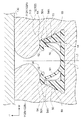
また、一対の係止爪52が互いに離間するように延設部50が弾性変形すると、図1に示されるように、突起54の下向面54Aが立上部56の頂面56Aに当接する(面接触する)ようになっている。
Further, when the extending
さらに、一対の係止爪52が、サスペンダ118を挟み込んで係止する際に夫々の延設部50が弾性変形した状態で、下向面54Aと頂面56Aとの間には、隙間60が形成されるようになっている(図4参照)。
Further, when the pair of locking
(作用)
次に、クリップ10の作用を、シート部材117、127に固定されているサスペンダ118をクリップ10に取り付ける作業、及びクッション112、122の成形後に行われるローラークラッシングによって説明する。
(Function)
Next, the operation of the
〔取付作業〕
サスペンダ118をクリップ10に取り付ける場合には、図3に示されるように、サスペンダ118を溝116、126に挿入する。サスペンダ118を溝116、126に挿入すると、先細りとされているサスペンダ118の先端側の部分と、一対の係止爪52とが当接する。
[Installation work]
When the
さらに、サスペンダ118を溝116、126の底面に向けて挿入すると、図4に示されるように、一対の係止爪52が互いに離間するように延設部50が弾性変形する。これより、サスペンダ118が一対の係止爪52の間を通過するのが許容される。この際、前述したように、突起54の下向面54Aと、立上部56の頂面56Aとは当接することなく、下向面54Aと頂面56Aとの間には、隙間60が形成される。
Further, when the
サスペンダ118の突起118Aが一対の係止爪52の間を通過すると、図5に示されるように、延設部50が弾性復帰し、一対の係止爪52がサスペンダ118を挟み込んで係止する。これにより、サスペンダ118が、クリップ10に取り付けられる。。
When the
このようにして、サスペンダ118をクリップ10に取り付ける取付作業が完了する。
In this way, the attaching operation for attaching the
〔ローラークラッシング〕
クッション112、122の成形後に、ローラークラッシングを行う場合には、図1に示されるように、ローラー130をクッション112、122の表面から押し付けながら転がす。これにより、クッション112、122に含まれる気泡の大きさが調整される。
[Roller crushing]
When roller crushing is performed after the formation of the
ここで、ローラー130をクッション112、122の表面から押し付けることで、クッション112、122が潰され、ローラー130による押付力が、部品上下方向の上方側から係止部34に伝達される。
Here, by pressing the
具体的には、係止爪52及び突起54を介して延設部50には、下方側に押し付けられる押付力が作用する。一対の延設部50は、前述したように、基端側に比して先端側が互いに離れるように部品幅方向の外側に傾斜している。このため、夫々の延設部50の先端側が離れるように延設部50が弾性変形する。そして、突起54の下向面54Aが立上部56の頂面56Aに当接する(面接触する)。これにより、延設部50の弾性変形が制限され、延設部50が過度に変形するのが抑制される。なお、立上部56には、突起54を介して下方側に押し付けられる押付力が作用する。
Specifically, a pressing force that is pressed downward acts on the
そして、クリップ10がローラー130の押付力から開放されると、図2に示されるように、延設部50が弾性復帰する。
When the
(効果)
以上説明したように、クッション112、122の成形後に、ローラークラッシングを行う場合には、一対の係止爪52が互いに離間するように延設部50が弾性変形し、突起54が立上部56に当接する。そして、延設部50が過度に変形するのが抑制される。これにより、ローラークラッシングを行う際に、クリップ10が破損してしまうのを抑制することができる。
(effect)
As described above, when roller crushing is performed after the formation of the
また、突起54が立上部56に当接する場合には、突起54の下向面54Aが立上部56の頂面56Aに当接する。ここで、立上部56は基部14の表面から部品上下方向に立ち上り、立上部56の先端側の部分に形成されている頂面56Aは上方側を向いている。このため、ローラークラッシングを行う際に突起54を介して下方側に押し付ける押付力が頂面56Aから立上部56に伝達されても、立上部56が部品上下方向に対して傾斜している場合と比して、立上部56が変形してしまうのを抑制することができる。
Further, when the
また、一対の係止爪52が、サスペンダ118を挟み込んで係止する際に夫々の延設部50が弾性変形した状態で、下向面54Aと頂面56Aとの間には、隙間60が形成されるようになっている。このため、サスペンダ118をクリップ10に取り付ける取付作業性が低下するのを抑制することができる。
In addition, when the pair of locking
また、一対の延設部50は、基端側に比して先端側が互いに離れるように部品幅方向の外側に傾斜している。このため、下方側に押し付ける押付力が延設部50に伝達されると、一対の係止爪52が互いに離間するように延設部50を弾性変形させることがきる。
Further, the pair of extending
なお、本発明を特定の実施形態について詳細に説明したが、本発明は係る実施形態に限定されるものではなく、本発明の範囲内にて他の種々の実施形態をとることが可能であることは当業者にとって明らかである。例えば、上記実施では、クリップ10を車両用のシート100に用いた場合を例にとって説明したが、クリップ10を事務椅子、家庭用のソファー、又は座椅子等の他のシート(椅子)に用いてもよい。
Although the present invention has been described in detail with respect to specific embodiments, the present invention is not limited to such embodiments, and various other embodiments can be taken within the scope of the present invention. This will be apparent to those skilled in the art. For example, in the above embodiment, the case where the
また、上記実施形態では、クリップ10に係止部34が2個備えられたが、1個でもよく、また3個以上であってもよい。
Moreover, in the said embodiment, although the
10 クリップ
14 基部
34 係止部
50 延設部
52 係止爪
54 突起
54A 下向面(当接面の一例)
56 立上部
56A 頂面
60 隙間
112 クッション(発泡体の一例)
114 表皮
118 サスペンダ(被係止部材の一例)
122 クッション(発泡体の一例)
124 表皮
10
56
114
122 Cushion (an example of foam)
124 epidermis
Claims (4)
前記基部から立ち上がり、対向して配置されている一対の延設部と、前記延設部の先端側に夫々形成され、前記発泡体を覆う表皮に取り付けられた被係止部材を挟み込んで係止する一対の係止爪と、を有する係止部と、
一対の前記延設部の先端側に夫々形成され、前記延設部が互いに対向する側とは反対側に突出する突起と、
前記基部から立ち上がり、一対の前記係止爪が互いに離間するように前記延設部が弾性変形すると、前記突起と当接する立上部と、を備え、
前記延設部の基端と、前記立上部の基端とは、離間している表皮係止用クリップ。 A plate-like base held by the foam;
A pair of extending portions that are arranged to rise from the base and are opposed to each other, and a locking member that is formed on the distal end side of the extending portion and that is attached to the skin covering the foam is sandwiched and locked A locking portion having a pair of locking claws,
A protrusion that is formed on the tip side of each of the pair of extending portions, and that protrudes on the opposite side to the side where the extending portions face each other;
A rising portion that abuts against the protrusion when the extended portion is elastically deformed so that the pair of the locking claws are separated from each other .
A clip for skin locking in which a base end of the extending portion and a base end of the upright portion are separated from each other .
前記基部から立ち上がり、対向して配置されている一対の延設部と、前記延設部の先端側に夫々形成され、前記発泡体を覆う表皮に取り付けられた被係止部材を挟み込んで係止する一対の係止爪と、を有する係止部と、
一対の前記延設部の先端側に夫々形成され、前記延設部が互いに対向する側とは反対側に突出する突起と、
前記基部から立ち上がり、一対の前記係止爪が互いに離間するように前記延設部が弾性変形すると、前記突起と当接する立上部と、を備え、
前記立上部の先端には、前記立上部が立ち上がる立上方向に向いた頂面が形成されており、
前記突起には、前記頂面と当接する当接面が形成されており、
一対の前記係止爪が互いに離間するように前記延設部が弾性変形した状態では、前記突起の前記当接面が前記立上部の前記頂面に面接触する表皮係止用クリップ。 A plate-like base held by the foam;
A pair of extending portions that are arranged to rise from the base and are opposed to each other, and a locking member that is formed on the distal end side of the extending portion and that is attached to the skin covering the foam is sandwiched and locked A locking portion having a pair of locking claws,
A protrusion that is formed on the tip side of each of the pair of extending portions, and that protrudes on the opposite side to the side where the extending portions face each other;
A rising portion that abuts against the protrusion when the extended portion is elastically deformed so that the pair of the locking claws are separated from each other .
A top surface facing the rising direction in which the rising portion rises is formed at the tip of the rising portion,
The protrusion is formed with a contact surface that contacts the top surface,
A skin locking clip in which the abutment surface of the projection comes into surface contact with the top surface of the upright portion in a state where the extended portion is elastically deformed so that a pair of the locking claws are separated from each other .
Priority Applications (4)
| Application Number | Priority Date | Filing Date | Title |
|---|---|---|---|
| JP2015066227A JP6345143B2 (en) | 2015-03-27 | 2015-03-27 | Skin clip |
| EP16161269.2A EP3072736B1 (en) | 2015-03-27 | 2016-03-18 | Cover anchor clip |
| CN201610173133.8A CN106004593B (en) | 2015-03-27 | 2016-03-24 | Cap anchor clamp tool |
| US15/081,205 US9751441B2 (en) | 2015-03-27 | 2016-03-25 | Cover anchor clip |
Applications Claiming Priority (1)
| Application Number | Priority Date | Filing Date | Title |
|---|---|---|---|
| JP2015066227A JP6345143B2 (en) | 2015-03-27 | 2015-03-27 | Skin clip |
Publications (2)
| Publication Number | Publication Date |
|---|---|
| JP2016186324A JP2016186324A (en) | 2016-10-27 |
| JP6345143B2 true JP6345143B2 (en) | 2018-06-20 |
Family
ID=55650149
Family Applications (1)
| Application Number | Title | Priority Date | Filing Date |
|---|---|---|---|
| JP2015066227A Active JP6345143B2 (en) | 2015-03-27 | 2015-03-27 | Skin clip |
Country Status (4)
| Country | Link |
|---|---|
| US (1) | US9751441B2 (en) |
| EP (1) | EP3072736B1 (en) |
| JP (1) | JP6345143B2 (en) |
| CN (1) | CN106004593B (en) |
Families Citing this family (10)
| Publication number | Priority date | Publication date | Assignee | Title |
|---|---|---|---|---|
| JP6228562B2 (en) * | 2015-03-27 | 2017-11-08 | 株式会社ニフコ | Skin clip |
| JP7048644B2 (en) | 2017-02-07 | 2022-04-05 | ホープ グローバル ディヴィジョン オブ エヌエフエイ コーポレイション | Clip assembly for decorative material listings |
| US10524545B2 (en) * | 2017-03-27 | 2020-01-07 | Kabushiki Kaisha Tokai-Rika-Denski-Seisakusho | Tongue for seatbelt device |
| CN110154843B (en) | 2018-02-13 | 2023-02-21 | 丰田纺织(中国)有限公司 | Clip for fixing covering |
| JP6979046B2 (en) | 2019-03-26 | 2021-12-08 | 株式会社ニフコ | Clip for locking the epidermis |
| US11332056B2 (en) * | 2019-08-22 | 2022-05-17 | Ykk Corporation | Seat cover fastening clip |
| CN112406649B (en) * | 2019-08-22 | 2023-04-18 | Ykk株式会社 | Seat cover fastening clip |
| JP7017285B2 (en) * | 2020-03-06 | 2022-02-08 | テイ・エス テック株式会社 | Vehicle seat and its assembly method |
| JP2023078023A (en) * | 2021-11-25 | 2023-06-06 | 株式会社ニフコ | Skin-locking clip |
| US11772533B2 (en) * | 2022-02-18 | 2023-10-03 | Ykk Corporation | Seat upholstery clip |
Family Cites Families (18)
| Publication number | Priority date | Publication date | Assignee | Title |
|---|---|---|---|---|
| CN1082465C (en) * | 1996-07-17 | 2002-04-10 | 美国3M公司 | Fastener member used as insert and method for connecting such fastener member with molded object |
| US5900303A (en) * | 1997-09-30 | 1999-05-04 | Aplix, Inc. | Fastener assembly with mechanical end seals |
| JP2001169871A (en) * | 1999-12-15 | 2001-06-26 | Suzuki Motor Corp | Assembling structure of seat trim |
| AU2003206527A1 (en) * | 2002-02-22 | 2003-09-09 | Woodbridge Foam Corporation | Attachment device |
| US6899399B2 (en) * | 2003-07-08 | 2005-05-31 | Lear Corporation | Attachment assembly for securing trim material to the padding of a vehicle seat |
| US7487575B2 (en) * | 2005-07-13 | 2009-02-10 | Lyle J Smith | System for attaching trim covers to a flexible substrate |
| US7481489B2 (en) * | 2007-03-16 | 2009-01-27 | Gm Global Technology Operations, Inc. | Vehicle seat assembly |
| US8091184B2 (en) * | 2007-04-19 | 2012-01-10 | Hope Global, Division Of Nfa Corp. | Festooned trim clip system and method for attaching festooned clips to a substrate |
| US8099837B2 (en) * | 2007-09-07 | 2012-01-24 | Hope Global, Division Of Nfa Corporation | Low-profile upholstery clip for attaching a bead to a foam substrate |
| US8197010B2 (en) * | 2008-11-12 | 2012-06-12 | Lear Corporation | Seat trim assembly |
| WO2010096933A1 (en) * | 2009-02-26 | 2010-09-02 | Magna Seating Inc. | Anti-rotation arrow retainer and clip |
| JP5388775B2 (en) * | 2009-08-24 | 2014-01-15 | 株式会社ニフコ | Clip and seat cover covering structure |
| JP3163446U (en) * | 2010-08-04 | 2010-10-14 | Ykk株式会社 | Skin material clip |
| FR2967949B1 (en) * | 2010-11-25 | 2012-11-16 | Peugeot Citroen Automobiles Sa | CLAMPING AND MASKING DEPTH FIXING DEVICE FOR A VEHICLE SEAT |
| US8998310B2 (en) * | 2012-09-07 | 2015-04-07 | Lear Corporation | Seat trim retention clip |
| WO2014139933A1 (en) * | 2013-03-13 | 2014-09-18 | Velcro Industries B.V. | Securing covers over foam cushions |
| DE202013101248U1 (en) * | 2013-03-22 | 2014-06-23 | Oke Automotive Gmbh & Co. Kg | Lock receiving element for attachment of covers on seat bodies and interior trim parts |
| JP3186511U (en) * | 2013-07-30 | 2013-10-10 | Ykk株式会社 | Skin material clip |
-
2015
- 2015-03-27 JP JP2015066227A patent/JP6345143B2/en active Active
-
2016
- 2016-03-18 EP EP16161269.2A patent/EP3072736B1/en active Active
- 2016-03-24 CN CN201610173133.8A patent/CN106004593B/en active Active
- 2016-03-25 US US15/081,205 patent/US9751441B2/en active Active
Also Published As
| Publication number | Publication date |
|---|---|
| CN106004593A (en) | 2016-10-12 |
| JP2016186324A (en) | 2016-10-27 |
| CN106004593B (en) | 2019-09-24 |
| US20160280105A1 (en) | 2016-09-29 |
| EP3072736A1 (en) | 2016-09-28 |
| EP3072736B1 (en) | 2019-09-11 |
| US9751441B2 (en) | 2017-09-05 |
Similar Documents
| Publication | Publication Date | Title |
|---|---|---|
| JP6345143B2 (en) | Skin clip | |
| JP6228562B2 (en) | Skin clip | |
| JP5472474B2 (en) | Seat backboard and vehicle seat | |
| JP5277912B2 (en) | Vehicle seat | |
| JP6346119B2 (en) | Skin clip | |
| JP6107460B2 (en) | Vehicle seat and manufacturing method thereof | |
| US10166892B2 (en) | Pad | |
| JP5649392B2 (en) | Seat cushion structure | |
| JP2022111251A (en) | posture holder | |
| JP2019138471A (en) | Skin locking clip | |
| US20170036580A1 (en) | Vehicle seat | |
| WO2023095509A1 (en) | Cover material fastening clip | |
| JP6030391B2 (en) | Chair | |
| JP6533156B2 (en) | Vehicle seat | |
| JP2021019771A (en) | Seat part of chair utilizable as carpet, and chair having the seat part | |
| JP2021041011A (en) | Cushion body | |
| JP7381968B2 (en) | sheet | |
| JP5569610B2 (en) | Vehicle seat | |
| JP2018177108A (en) | Vehicle seat | |
| JP2014223111A (en) | Vehicle seat | |
| JP2005034298A (en) | Seat shell structure of chair | |
| JP2020156629A (en) | Skin locking clip | |
| JP2020062271A (en) | Seat pad | |
| JP2010162966A (en) | Seat cushion for vehicular seat | |
| JP2009143471A (en) | Seat for vehicle |
Legal Events
| Date | Code | Title | Description |
|---|---|---|---|
| A621 | Written request for application examination |
Free format text: JAPANESE INTERMEDIATE CODE: A621 Effective date: 20170106 |
|
| A977 | Report on retrieval |
Free format text: JAPANESE INTERMEDIATE CODE: A971007 Effective date: 20170908 |
|
| A131 | Notification of reasons for refusal |
Free format text: JAPANESE INTERMEDIATE CODE: A131 Effective date: 20170919 |
|
| A521 | Request for written amendment filed |
Free format text: JAPANESE INTERMEDIATE CODE: A523 Effective date: 20171110 |
|
| TRDD | Decision of grant or rejection written | ||
| A01 | Written decision to grant a patent or to grant a registration (utility model) |
Free format text: JAPANESE INTERMEDIATE CODE: A01 Effective date: 20180424 |
|
| A61 | First payment of annual fees (during grant procedure) |
Free format text: JAPANESE INTERMEDIATE CODE: A61 Effective date: 20180522 |
|
| R150 | Certificate of patent or registration of utility model |
Ref document number: 6345143 Country of ref document: JP Free format text: JAPANESE INTERMEDIATE CODE: R150 |
|
| R250 | Receipt of annual fees |
Free format text: JAPANESE INTERMEDIATE CODE: R250 |
|
| R250 | Receipt of annual fees |
Free format text: JAPANESE INTERMEDIATE CODE: R250 |
|
| R250 | Receipt of annual fees |
Free format text: JAPANESE INTERMEDIATE CODE: R250 |