JP6342482B2 - Channel state information (CSI) measurement and reporting for extended interference management (eIMTA) for traffic adaptation in LTE - Google Patents
Channel state information (CSI) measurement and reporting for extended interference management (eIMTA) for traffic adaptation in LTE Download PDFInfo
- Publication number
- JP6342482B2 JP6342482B2 JP2016514058A JP2016514058A JP6342482B2 JP 6342482 B2 JP6342482 B2 JP 6342482B2 JP 2016514058 A JP2016514058 A JP 2016514058A JP 2016514058 A JP2016514058 A JP 2016514058A JP 6342482 B2 JP6342482 B2 JP 6342482B2
- Authority
- JP
- Japan
- Prior art keywords
- flexible subframe
- channel
- subframe
- current flexible
- subframes
- Prior art date
- Legal status (The legal status is an assumption and is not a legal conclusion. Google has not performed a legal analysis and makes no representation as to the accuracy of the status listed.)
- Active
Links
Images


Classifications
-
- H—ELECTRICITY
- H04—ELECTRIC COMMUNICATION TECHNIQUE
- H04W—WIRELESS COMMUNICATION NETWORKS
- H04W24/00—Supervisory, monitoring or testing arrangements
- H04W24/10—Scheduling measurement reports ; Arrangements for measurement reports
-
- H—ELECTRICITY
- H04—ELECTRIC COMMUNICATION TECHNIQUE
- H04B—TRANSMISSION
- H04B7/00—Radio transmission systems, i.e. using radiation field
- H04B7/02—Diversity systems; Multi-antenna system, i.e. transmission or reception using multiple antennas
- H04B7/04—Diversity systems; Multi-antenna system, i.e. transmission or reception using multiple antennas using two or more spaced independent antennas
- H04B7/06—Diversity systems; Multi-antenna system, i.e. transmission or reception using multiple antennas using two or more spaced independent antennas at the transmitting station
- H04B7/0613—Diversity systems; Multi-antenna system, i.e. transmission or reception using multiple antennas using two or more spaced independent antennas at the transmitting station using simultaneous transmission
- H04B7/0615—Diversity systems; Multi-antenna system, i.e. transmission or reception using multiple antennas using two or more spaced independent antennas at the transmitting station using simultaneous transmission of weighted versions of same signal
- H04B7/0619—Diversity systems; Multi-antenna system, i.e. transmission or reception using multiple antennas using two or more spaced independent antennas at the transmitting station using simultaneous transmission of weighted versions of same signal using feedback from receiving side
- H04B7/0621—Feedback content
- H04B7/0626—Channel coefficients, e.g. channel state information [CSI]
-
- H—ELECTRICITY
- H04—ELECTRIC COMMUNICATION TECHNIQUE
- H04B—TRANSMISSION
- H04B7/00—Radio transmission systems, i.e. using radiation field
- H04B7/24—Radio transmission systems, i.e. using radiation field for communication between two or more posts
- H04B7/26—Radio transmission systems, i.e. using radiation field for communication between two or more posts at least one of which is mobile
- H04B7/2643—Radio transmission systems, i.e. using radiation field for communication between two or more posts at least one of which is mobile using time-division multiple access [TDMA]
- H04B7/2656—Radio transmission systems, i.e. using radiation field for communication between two or more posts at least one of which is mobile using time-division multiple access [TDMA] for structure of frame, burst
-
- H—ELECTRICITY
- H04—ELECTRIC COMMUNICATION TECHNIQUE
- H04L—TRANSMISSION OF DIGITAL INFORMATION, e.g. TELEGRAPHIC COMMUNICATION
- H04L1/00—Arrangements for detecting or preventing errors in the information received
- H04L1/0001—Systems modifying transmission characteristics according to link quality, e.g. power backoff
- H04L1/0023—Systems modifying transmission characteristics according to link quality, e.g. power backoff characterised by the signalling
- H04L1/0026—Transmission of channel quality indication
-
- H—ELECTRICITY
- H04—ELECTRIC COMMUNICATION TECHNIQUE
- H04L—TRANSMISSION OF DIGITAL INFORMATION, e.g. TELEGRAPHIC COMMUNICATION
- H04L5/00—Arrangements affording multiple use of the transmission path
- H04L5/003—Arrangements for allocating sub-channels of the transmission path
- H04L5/0048—Allocation of pilot signals, i.e. of signals known to the receiver
- H04L5/005—Allocation of pilot signals, i.e. of signals known to the receiver of common pilots, i.e. pilots destined for multiple users or terminals
-
- H—ELECTRICITY
- H04—ELECTRIC COMMUNICATION TECHNIQUE
- H04L—TRANSMISSION OF DIGITAL INFORMATION, e.g. TELEGRAPHIC COMMUNICATION
- H04L5/00—Arrangements affording multiple use of the transmission path
- H04L5/14—Two-way operation using the same type of signal, i.e. duplex
- H04L5/1469—Two-way operation using the same type of signal, i.e. duplex using time-sharing
-
- H—ELECTRICITY
- H04—ELECTRIC COMMUNICATION TECHNIQUE
- H04W—WIRELESS COMMUNICATION NETWORKS
- H04W72/00—Local resource management
- H04W72/04—Wireless resource allocation
- H04W72/044—Wireless resource allocation based on the type of the allocated resource
- H04W72/0446—Resources in time domain, e.g. slots or frames
-
- H—ELECTRICITY
- H04—ELECTRIC COMMUNICATION TECHNIQUE
- H04W—WIRELESS COMMUNICATION NETWORKS
- H04W72/00—Local resource management
- H04W72/50—Allocation or scheduling criteria for wireless resources
- H04W72/54—Allocation or scheduling criteria for wireless resources based on quality criteria
- H04W72/542—Allocation or scheduling criteria for wireless resources based on quality criteria using measured or perceived quality
Description
米国特許法第119条の下での優先権の主張
[0001]本出願は、2013年5月17日に出願された米国特許仮出願第61/824,533号、及び2014年5月13日に出願された米国特許出願第14/275,942号の利益を主張するものであり、これらの両方の全体が参照により本明細書に組み込まれる。
Claiming priority under 35 USC 119
[0001] This application is filed in US Provisional Application No. 61 / 824,533, filed May 17, 2013, and US Patent Application No. 14 / 275,942, filed May 13, 2014. Both of which are hereby incorporated by reference in their entirety.
[0002]本開示の特定の態様は、一般に、ワイヤレス通信に関し、より詳細には、ロングタームエボリューション(LTE)における、トラフィック適応のための拡張された干渉管理(eIMTA:enhanced interference management for traffic adaptation)のための、チャネル状態情報(CSI)の測定及び報告の技法に関する。 [0002] Certain aspects of the present disclosure relate generally to wireless communications, and more particularly to enhanced interference management for traffic adaptation (eIMTA) in Long Term Evolution (LTE). For channel state information (CSI) measurement and reporting techniques.
[0003]ワイヤレス通信ネットワークは、音声、ビデオ、パケットデータ、メッセージング、ブロードキャスト等の様々な通信サービスを提供するために、幅広く展開されている。これらのワイヤレスネットワークは、利用可能なネットワークリソースを共有することにより、マルチプルなユーザをサポートすることができる多元接続ネットワークであり得る。このような多元接続ネットワークの例は、符号分割多元接続(CDMA)ネットワーク、時分割多元接続(TDMA)ネットワーク、周波数分割多元接続(FDMA)ネットワーク、直交FDMA(OFDMA)ネットワーク、及びシングルキャリアFDMA(SC−FDMA)ネットワークを含む。 [0003] Wireless communication networks are widely deployed to provide various communication services such as voice, video, packet data, messaging, broadcast, and the like. These wireless networks can be multiple access networks that can support multiple users by sharing available network resources. Examples of such multiple access networks include code division multiple access (CDMA) networks, time division multiple access (TDMA) networks, frequency division multiple access (FDMA) networks, orthogonal FDMA (OFDMA) networks, and single carrier FDMA (SC). -FDMA) network.
[0004]ワイヤレス通信ネットワークは、いくつかのユーザ機器(UE)のための通信をサポートすることが可能な、いくつかの基地局を含み得る。UEは、ダウンリンク及びアップリンクを介して基地局と通信し得る。ダウンリンク(即ち順方向リンク)は、基地局からUEへの通信リンクを指し、アップリンク(即ち逆方向リンク)は、UEから基地局への通信リンクを指す。 [0004] A wireless communication network may include a number of base stations that can support communication for a number of user equipments (UEs). The UE may communicate with the base station via the downlink and uplink. The downlink (ie, forward link) refers to the communication link from the base station to the UE, and the uplink (ie, reverse link) refers to the communication link from the UE to the base station.
[0005]基地局は、ダウンリンクにおいてUEにデータ及び制御情報を送信することができ、及び/又はアップリンクにおいてUEからデータ及び制御情報を受信することができる。ダウンリンクにおいて、基地局からの送信は、近隣の基地局からの送信に起因する干渉を観測し得る。アップリンクにおいて、UEからの送信は、近隣の基地局と通信する他のUEからの送信に対して干渉を引き起こし得る。干渉は、ダウンリンク及びアップリンクの両方で性能を低下させ得る。 [0005] A base station may transmit data and control information to the UE on the downlink and / or receive data and control information from the UE on the uplink. On the downlink, transmissions from the base station may observe interference due to transmissions from neighboring base stations. On the uplink, transmissions from the UE may cause interference with transmissions from other UEs communicating with neighboring base stations. Interference can degrade performance on both the downlink and uplink.
[0006]ロングタームエボリューション(LTE)におけるトラフィック適応のための拡張された干渉管理(eIMTA)のためのチャネル状態情報(CSI)の測定及び報告のための技法及び装置が、本明細書で提供される。 [0006] Provided herein are techniques and apparatus for channel state information (CSI) measurement and reporting for extended interference management (eIMTA) for traffic adaptation in Long Term Evolution (LTE). The
[0007]本開示の特定の態様は、ユーザ機器(UE)によるワイヤレス通信の方法を提供する。この方法は一般に、アップリンク通信又はダウンリンク通信のいずれかについて動的に管理され得る1つまたは複数のフレキシブルサブフレームを、サブフレームのセット内で識別することと、現在のフレキシブルサブフレームがアップリンク通信のためのものか又はダウンリンク通信のためのものかを決定することと、決定に基づいて、チャネル測定、干渉測定、又はチャネル状態報告のうちの少なくとも1つを実行することとを含む。 [0007] Certain aspects of the present disclosure provide a method of wireless communication by a user equipment (UE). This method generally identifies one or more flexible subframes in a set of subframes that can be dynamically managed for either uplink or downlink communication, and the current flexible subframe is up. Determining whether it is for link communication or downlink communication and performing at least one of channel measurement, interference measurement, or channel condition reporting based on the determination .
[0008]本開示の特定の態様は、基地局によるワイヤレス通信の方法を提供する。この方法は一般に、アップリンク通信又はダウンリンク通信のいずれかについて動的に管理され得る1つまたは複数のフレキシブルサブフレームを、サブフレームのセット内で識別することと、現在のフレキシブルサブフレームがアップリンク通信のためのものか又はダウンリンク通信のためのものかを決定することと、ユーザ機器(UE)からチャネル状態情報(CSI)フィードバックを受信することと、決定に基づいてCSIフィードバックを処理することとを含む。 [0008] Certain aspects of the present disclosure provide a method of wireless communication by a base station. This method generally identifies one or more flexible subframes in a set of subframes that can be dynamically managed for either uplink or downlink communication, and the current flexible subframe is up. Determining whether it is for link communication or downlink communication; receiving channel state information (CSI) feedback from user equipment (UE); and processing CSI feedback based on the determination Including.
[0009]本開示の特定の態様は、ユーザ機器(UE)によるワイヤレス通信の方法を提供する。この方法は一般に、アップリンク通信又はダウンリンク通信のいずれかについて動的に管理され得る1つまたは複数のフレキシブルサブフレームを、サブフレームのセット内で識別することと、現在のサブフレームが固定サブフレームであるか又はフレキシブルサブフレームであるかを決定することと、決定に基づいてダウンリンクチャネル測定を実行することとを含む。 [0009] Certain aspects of the present disclosure provide a method of wireless communication by a user equipment (UE). This method generally identifies one or more flexible subframes within a set of subframes that can be dynamically managed for either uplink or downlink communication, and the current subframe is a fixed subframe. Determining whether it is a frame or a flexible subframe and performing downlink channel measurements based on the determination.
[0010]本開示の特定の態様は、ユーザ機器(UE)によるワイヤレス通信のための装置を提供する。該装置は一般に、アップリンク通信又はダウンリンク通信のいずれかについて動的に管理され得る1つまたは複数のフレキシブルサブフレームを、サブフレームのセット内で識別することと、現在のフレキシブルサブフレームがアップリンク通信のためのものか又はダウンリンク通信のためのものかを決定することと、決定に基づいて、チャネル測定、干渉測定、又はチャネル状態報告のうちの少なくとも1つを実行することと、を行うように構成された、少なくとも1つのプロセッサを含む。装置は、また、一般に、少なくとも1つのプロセッサに結合されたメモリも含む。 [0010] Certain aspects of the present disclosure provide an apparatus for wireless communication by a user equipment (UE). The apparatus generally identifies one or more flexible subframes in a set of subframes that can be dynamically managed for either uplink or downlink communication, and the current flexible subframe is up. Determining whether it is for link communication or downlink communication, and performing at least one of channel measurement, interference measurement, or channel condition reporting based on the determination. Including at least one processor configured to perform. The apparatus also typically includes a memory coupled to at least one processor.
[0011]本開示の特定の態様は、基地局によるワイヤレス通信のための装置を提供する。該装置は一般に、アップリンク通信又はダウンリンク通信のいずれかについて動的に管理され得る1つまたは複数のフレキシブルサブフレームを、サブフレームのセット内で識別することと、現在のフレキシブルサブフレームがアップリンク通信のためのものか又はダウンリンク通信のためのものかを決定することと、ユーザ機器(UE)からチャネル状態情報(CSI)フィードバックを受信することと、決定に基づいてCSIフィードバックを処理することと、を行うように構成された、少なくとも1つのプロセッサを含む。装置は、また、一般に、少なくとも1つのプロセッサに結合されたメモリも含む。 [0011] Certain aspects of the present disclosure provide an apparatus for wireless communication by a base station. The apparatus generally identifies one or more flexible subframes in a set of subframes that can be dynamically managed for either uplink or downlink communication, and the current flexible subframe is up. Determining whether it is for link communication or downlink communication; receiving channel state information (CSI) feedback from user equipment (UE); and processing CSI feedback based on the determination And at least one processor configured to do so. The apparatus also typically includes a memory coupled to at least one processor.
[0012]本開示の特定の態様は、ユーザ機器(UE)によるワイヤレス通信のための装置を提供する。該装置は一般に、アップリンク通信又はダウンリンク通信のいずれかについて動的に管理され得る1つまたは複数のフレキシブルサブフレームを、サブフレームのセット内で識別することと、現在のサブフレームが固定サブフレームであるか又はフレキシブルサブフレームであるかを決定することと、決定に基づいてダウンリンクチャネル測定を実行することと、を行うように構成された、少なくとも1つのプロセッサを含む。装置は、また、一般に、少なくとも1つのプロセッサに結合されたメモリも含む。 [0012] Certain aspects of the present disclosure provide an apparatus for wireless communication by a user equipment (UE). The apparatus generally identifies one or more flexible subframes in a set of subframes that can be dynamically managed for either uplink or downlink communication, and the current subframe is a fixed subframe. At least one processor configured to determine whether it is a frame or a flexible subframe and to perform a downlink channel measurement based on the determination. The apparatus also typically includes a memory coupled to at least one processor.
[0013]本開示の特定の態様は、ユーザ機器(UE)によるワイヤレス通信のための装置を提供する。該装置は一般に、アップリンク通信又はダウンリンク通信のいずれかについて動的に管理され得る1つまたは複数のフレキシブルサブフレームを、サブフレームのセット内で識別するための手段と、現在のフレキシブルサブフレームがアップリンク通信のためのものか又はダウンリンク通信のためのものかを決定するための手段と、決定に基づいて、チャネル測定、干渉測定、又はチャネル状態報告のうちの少なくとも1つを実行するための手段とを含む。 [0013] Certain aspects of the present disclosure provide an apparatus for wireless communication by a user equipment (UE). The apparatus generally includes a means for identifying within a set of subframes one or more flexible subframes that can be dynamically managed for either uplink or downlink communications, and a current flexible subframe. Performing at least one of a channel measurement, an interference measurement, or a channel condition report based on the means and means for determining whether the is for uplink communication or downlink communication Means.
[0014]本開示の特定の態様は、ユーザ機器(UE)によるワイヤレス通信のための装置を提供する。該装置は一般に、アップリンク通信又はダウンリンク通信のいずれかについて動的に管理され得る1つまたは複数のフレキシブルサブフレームを、サブフレームのセット内で識別するための手段と、現在のサブフレームが固定サブフレームであるか又はフレキシブルサブフレームであるかを決定するための手段と、決定に基づいてダウンリンクチャネル測定を実行するための手段とを含む。 [0014] Certain aspects of the present disclosure provide an apparatus for wireless communication by a user equipment (UE). The apparatus generally includes a means for identifying within a set of subframes one or more flexible subframes that can be dynamically managed for either uplink or downlink communications, Means for determining whether it is a fixed subframe or a flexible subframe and means for performing downlink channel measurements based on the determination.
[0015]本開示の特定の態様は、ユーザ機器(UE)によるワイヤレス通信のためのコンピュータプログラム製品を提供する。該コンピュータプログラム製品は一般に、アップリンク通信又はダウンリンク通信のいずれかについて動的に管理され得る1つまたは複数のフレキシブルサブフレームを、サブフレームのセット内で識別することと、現在のフレキシブルサブフレームがアップリンク通信のためのものか又はダウンリンク通信のためのものかを決定することと、決定に基づいて、チャネル測定、干渉測定、又はチャネル状態報告のうちの少なくとも1つを実行することと、のためのコードを備える、コンピュータ可読媒体を含む。 [0015] Certain aspects of the present disclosure provide a computer program product for wireless communication by a user equipment (UE). The computer program product generally identifies one or more flexible subframes within a set of subframes that can be dynamically managed for either uplink or downlink communication, and the current flexible subframe. Determining whether is for uplink communication or downlink communication, and performing at least one of channel measurement, interference measurement, or channel condition reporting based on the determination A computer-readable medium comprising code for.
[0016]本開示の特定の態様は、ユーザ機器(UE)によるワイヤレス通信のためのコンピュータプログラム製品を提供する。該コンピュータプログラム製品は一般に、アップリンク通信又はダウンリンク通信のいずれかについて動的に管理され得る1つまたは複数のフレキシブルサブフレームを、サブフレームのセット内で識別することと、現在のサブフレームが固定サブフレームであるか又はフレキシブルサブフレームであるかを決定することと、決定に基づいてダウンリンクチャネル測定を実行することと、のためのコードを備える、コンピュータ可読媒体を含む。 [0016] Certain aspects of the present disclosure provide a computer program product for wireless communication by a user equipment (UE). The computer program product generally identifies one or more flexible subframes within a set of subframes that can be dynamically managed for either uplink or downlink communications, and the current subframe is A computer-readable medium comprising code for determining whether it is a fixed subframe or a flexible subframe and performing downlink channel measurements based on the determination.
[0017]方法、装置、システム、コンピュータプログラム製品、及び処理システムを含む、多数の他の態様が提供される。 [0017] Numerous other aspects are provided, including methods, apparatus, systems, computer program products, and processing systems.
[0018]本開示の上記の特徴が詳細に理解されるように、以上では簡単に要約されたことのより詳細な説明が諸態様への参照によってなされ、それらの態様のいくつかは、添付の図面に示されている。しかしながら、添付の図面は、本開示の特定の典型的な態様のみを示しており、したがって、説明は、他の同等に効果的な態様を容認し得るので、本開示の範囲を限定するものと見なされるべきではないことに留意されたい。 [0018] In order that the above features of the present disclosure may be understood in detail, a more detailed description of what has been briefly summarized above has been made by reference to aspects, some of which are Shown in the drawing. However, the attached drawings illustrate only certain typical aspects of the present disclosure and, therefore, the description is intended to limit the scope of the present disclosure, as other equally effective aspects may be tolerated. Note that it should not be considered.
[0030]ロングタームエボリューション(LTE)におけるトラフィック適応のための拡張された干渉管理(eIMTA)のためのチャネル状態情報(CSI)の測定及び報告のための技法及び装置が、本明細書で提供される。特定の態様によれば、ユーザ機器(UE)は、固定サブフレーム又はフレキシブルサブフレームとしてサブフレームを識別し得る。UEはまた、例えば、受信されたシグナリング又はブラインド検出により、サブフレームがアップリンク送信専用又はダウンリンク送信専用であるかを決定し得る。フレキシブルサブフレームがアップリンクサブフレームであると決定された場合、UEは、そのサブフレームについての干渉測定及び/又はCSI測定フィルタリングをスキップし得る。代替的には、UEは、システム帯域幅の一部、又は全部を使用して、干渉測定を実施し得る。UEはまた、そのサブフレームについてのCSI報告を省略し得る。代替的には、UEは、通常通りに報告し、または所定の値を報告し得る。特定の態様によれば、UEは、ダウンリンクチャネル測定に使用され得るサブフレームの最後のシンボルにおいて、新たなCSI基準信号(CSI−RS)及び干渉測定リソース(IMR)構成を指定し得る。UEはまた、ダウンリンク測定に関して無効なサブフレームとして、すべてのフレキシブルサブフレームを指定し得る。 [0030] Techniques and apparatus for channel state information (CSI) measurement and reporting for extended interference management (eIMTA) for traffic adaptation in Long Term Evolution (LTE) are provided herein. The According to certain aspects, user equipment (UE) may identify a subframe as a fixed subframe or a flexible subframe. The UE may also determine whether the subframe is dedicated for uplink transmission or downlink transmission, eg, by received signaling or blind detection. If the flexible subframe is determined to be an uplink subframe, the UE may skip interference measurement and / or CSI measurement filtering for that subframe. Alternatively, the UE may perform interference measurements using some or all of the system bandwidth. The UE may also omit CSI reporting for that subframe. Alternatively, the UE may report as usual or report a predetermined value. According to certain aspects, the UE may specify a new CSI reference signal (CSI-RS) and interference measurement resource (IMR) configuration in the last symbol of a subframe that may be used for downlink channel measurements. The UE may also designate all flexible subframes as invalid subframes for downlink measurements.
[0031]本明細書に説明される技法は、CDMA、TDMA、FDMA、OFDMA、SC−FDMA、及び他のネットワーク等の、様々なワイヤレス通信ネットワークに使用され得る。「ネットワーク」及び「システム」という用語は、しばしば交換可能に使用される。CDMAネットワークは、ユニバーサル地上無線アクセス(UTRA)、cdma2000等の無線技術を実装し得る。UTRAは、広帯域CDMA(WCDMA(登録商標))、及びCDMAの他の変形を含む。cdma2000は、IS−2000規格、IS−95規格、及びIS−856規格をカバーする。TDMAネットワークは、グローバルシステムフォーモバイルコミュニケーションズ(GSM(登録商標))等の無線技術を実装し得る。OFDMAネットワークは、発展型UTRA(E−UTRA)、ウルトラモバイルブロードバンド(UMB)、IEEE802.11(WiFi)、IEEE802.16(WiMAX)、IEEE802.20、フラッシュ−OFDM(登録商標)等の無線技術を実装し得る。UTRA、及びE−UTRAは、ユニバーサルモバイルテレコミュニケーションシステム(UMTS)の一部である。3GPPロングタームエボリューション(LTE)、及びLTEアドバンスト(LTE−A)は、E−UTRAを使用するUMTSの新たなリリースである。UTRA、E−UTRA、UMTS、LTE、LTE−A、及びGSM(登録商標)は、「第3世代パートナーシッププロジェクト」(3GPP)という名称の団体からの文書に説明されている。cdma2000及びUMBは、「第3世代パートナーシッププロジェクト2」(3GPP2)という名称の団体からの文書に説明されている。本明細書に説明される技法は、上述のワイヤレスネットワーク、及び無線技術、並びに他のワイヤレスネットワーク、及び無線技術のために使用され得る。明確にするために、以下では、技法の特定の態様がLTE/LTE−Aに関して説明され、以下の説明の多くにおいてLTE/LTE−Aの用語が使用される。
[0031] The techniques described herein may be used for various wireless communication networks such as CDMA, TDMA, FDMA, OFDMA, SC-FDMA, and other networks. The terms “network” and “system” are often used interchangeably. A CDMA network may implement a radio technology such as Universal Terrestrial Radio Access (UTRA), cdma2000, etc. UTRA includes Wideband CDMA (WCDMA®) and other variants of CDMA. cdma2000 covers IS-2000, IS-95, and IS-856 standards. A TDMA network may implement a radio technology such as Global System for Mobile Communications (GSM). The OFDMA network uses wireless technologies such as Evolved UTRA (E-UTRA), Ultra Mobile Broadband (UMB), IEEE 802.11 (WiFi), IEEE 802.16 (WiMAX), IEEE 802.20, and Flash-OFDM (registered trademark). Can be implemented. UTRA and E-UTRA are part of Universal Mobile Telecommunication System (UMTS). 3GPP Long Term Evolution (LTE) and LTE Advanced (LTE-A) are new releases of UMTS that use E-UTRA. UTRA, E-UTRA, UMTS, LTE, LTE-A, and GSM® are described in documents from an organization named “3rd Generation Partnership Project” (3GPP). cdma2000 and UMB are described in documents from an organization named “3rd
例示的なワイヤレス通信ネットワーク
[0032]図1は、ロングタームエボリューション(LTE)ネットワークであり得る、ワイヤレス通信ネットワーク100を示す。ワイヤレスネットワーク100は、いくつもの発展型ノードB(eNB)110及び他のネットワークエンティティを含み得る。eNBは、ユーザ機器デバイス(UE)と通信する局であり、また、基地局、ノードB、アクセスポイント等と呼ばれ得る。各eNB110は、特定の地理的エリアに通信カバレッジを提供し得る。3GPPでは、「セル」という用語は、この用語が使用される文脈により、eNBのカバレッジエリア、及び/又はこのカバレッジエリアにサービスを提供するeNBサブシステムを指し得る。
Exemplary wireless communication network
[0032] FIG. 1 shows a
[0033]eNBは、マクロセル、ピコセル、フェムトセル、及び/又は他のタイプのセルに通信カバレッジを提供し得る。マクロセルは、比較的大きな地理的エリア(例えば、半径数キロメートル)をカバーし、サービスに加入済みのUEによる無制限のアクセスを許可し得る。ピコセルは、比較的小さな地理的エリアをカバーし、サービスに加入済みのUEによる無制限のアクセスを許可し得る。フェムトセルは、比較的小さな地理的エリア(例えば、家)をカバーし、フェムトセルとの関連付けを有するUE(例えば、クローズド加入者グループ(CSG)のUE、家庭内のユーザ用のUE等)による、制限されたアクセスを許可し得る。マクロセル用のeNBは、マクロeNB(即ちマクロ基地局)と呼ばれ得る。ピコセル用のeNBは、ピコeNB(即ちピコ基地局)と呼ばれ得る。フェムトセル用のeNBは、フェムトeNB(即ちフェムト基地局)、又はホームeNBと呼ばれ得る。図1に示される例では、eNB110a、eNB110b、及びeNB110cは、それぞれ、マクロセル102a、マクロセル102b、及びマクロセル102c用のマクロeNBであり得る。eNB110xは、ピコセル102x用のピコeNBであり得る。eNB110y、及びeNB110zは、それぞれ、フェムトセル102y、及びフェムトセル102z用のフェムトeNBであり得る。eNBは、1つ又はマルチプルな(例えば、3つの)セルをサポートし得る。
[0033] An eNB may provide communication coverage for a macro cell, a pico cell, a femto cell, and / or other types of cell. A macro cell may cover a relatively large geographic area (eg, a few kilometers in radius) and allow unrestricted access by UEs that have subscribed to the service. A pico cell may cover a relatively small geographic area and allow unrestricted access by UEs that have subscribed to the service. A femto cell covers a relatively small geographic area (eg, a home) and has a UE associated with the femto cell (eg, a closed subscriber group (CSG) UE, a UE for a user in a home, etc.) May allow limited access. An eNB for a macro cell may be referred to as a macro eNB (ie, a macro base station). An eNB for a pico cell may be referred to as a pico eNB (ie, a pico base station). An eNB for a femto cell may be referred to as a femto eNB (ie, a femto base station) or a home eNB. In the example shown in FIG. 1,
[0034]ワイヤレスネットワーク100はまた、中継局を含み得る。中継局は、上流局(例えば、eNB又はUE)からデータ及び/又は他の情報の伝送を受信し、下流局(例えば、UE又はeNB)にデータ及び/又は他の情報の伝送を送信する局である。中継局はまた、他のUEために伝送を中継するUE(例えば、UE中継局)であり得る。図1に示される例では、中継局110rは、eNB110aとUE120rとの間の通信を容易にするために、eNB110a及びUE120rと通信し得る。中継局はまた、中継eNB、中継器等とも呼ばれ得る。
[0034] The
[0035]ワイヤレスネットワーク100は、例えば、マクロeNB、ピコeNB、フェムトeNB、中継器等の、異なるタイプのeNBを含む、異種ネットワーク(HetNet)であり得る。これらの異なるタイプのeNBは、ワイヤレスネットワーク100において、異なる伝送電力レベル、異なるカバレッジエリア、及び干渉についての異なる影響力を有し得る。例えば、マクロeNBは、高伝送電力レベル(例えば、20ワット)を有し、一方、ピコeNB、フェムトeNB、及び中継器は、より低い伝送電力レベル(例えば、1ワット)を有し得る。
[0035] The
[0036]ワイヤレスネットワーク100は、同期動作又は非同期動作をサポートし得る。同期動作について、eNBは、類似のフレームタイミングを有し、異なるeNBからの伝送は、時間的にほぼ揃えられ(aligned)得る。非同期動作について、eNBは、異なるフレームタイミングを有し、異なるeNBからの伝送は、時間的に揃えられない。本明細書に説明される技法は、同期動作及び非同期動作の両方のために使用され得る。
[0036] The
[0037]ネットワークコントローラ130は、1セットのeNBに結合し、これらのeNBのために、調整及び制御を提供し得る。ネットワークコントローラ130は、バックホールを介してeNB110と通信し得る。eNB110はまた、例えば、ワイヤレス又はワイヤラインバックホールを介して間接的に、または直接的に、互いと通信し得る。
[0037] The
[0038]UE120(例えば、120x、120y)は、ワイヤレスネットワーク100全体にわたって分散され、各UEは、固定式又は移動式であり得る。UEはまた、端末、移動局、加入者ユニット、局等と呼ばれ得る。UEは、携帯電話、スマートフォン、携帯情報端末(PDA)、ワイヤレスモデム、ワイヤレス通信デバイス、ハンドヘルドデバイス、ラップトップ/ノートブックコンピュータ、コードレス電話、ワイヤレスローカルループ(WLL)局、タブレット等であり得る。UEは、マクロeNB、ピコeNB、フェムトeNB、中継器等と通信することができ得る。図1では、両矢印付きの実線が、UEとサービングeNBとの間の望ましい伝送を示し、サービングeNBとは、ダウンリンク及び/又はアップリンクにおいてUEにサービスを提供するように指定されたeNBである。両矢印付きの破線は、UEとeNBとの間の干渉伝送を示す。特定の態様について、UEは、LTEリリース10のUEを備え得る。
[0038] UEs 120 (eg, 120x, 120y) are distributed throughout the
[0039]LTEは、ダウンリンクにおいては直交周波数分割多重(OFDM)を、アップリンクにおいてはシングルキャリア周波数分割多重(SC−FDM)を利用する。OFDM及びSC−FDMは、システム帯域幅をマルチプルな(K個の)直交サブキャリアに区切り、これらのサブキャリアはまた、通常、トーン、ビン等とも呼ばれる。各サブキャリアは、データで変調され得る。一般に、変調シンボルは、OFDMにより周波数領域において、及びSC−FDMにより時間領域において送信される。隣接するサブキャリア間の間隔は固定され、サブキャリアの総数(K個)は、システム帯域幅に依存し得る。例えば、Kは、それぞれ、1.25、2.5、5、10、又は20メガヘルツ(MHz)のシステム帯域幅について、128、256、512、1024、又は2048に等しいものであり得る。システム帯域幅はまた、サブバンドに区切られ得る。例えば、サブバンドは、1.08MHzをカバーし、1.25、2.5、5、10、又は20MHzのシステム帯域幅について、それぞれ、1個、2個、4個、8個、又は16個のサブバンドがあり得る。 [0039] LTE utilizes orthogonal frequency division multiplexing (OFDM) in the downlink and single carrier frequency division multiplexing (SC-FDM) in the uplink. OFDM and SC-FDM partition the system bandwidth into multiple (K) orthogonal subcarriers, which are also commonly referred to as tones, bins, etc. Each subcarrier may be modulated with data. In general, modulation symbols are sent in the frequency domain with OFDM and in the time domain with SC-FDM. The spacing between adjacent subcarriers is fixed, and the total number of subcarriers (K) may depend on the system bandwidth. For example, K may be equal to 128, 256, 512, 1024, or 2048 for a system bandwidth of 1.25, 2.5, 5, 10, or 20 megahertz (MHz), respectively. The system bandwidth can also be divided into subbands. For example, the subband covers 1.08 MHz and is 1, 2, 4, 8, or 16 for a system bandwidth of 1.25, 2.5, 5, 10, or 20 MHz, respectively. There may be subbands.
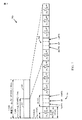
[0040]図2は、LTEで使用されるフレーム構造を示す。ダウンリンク用の伝送タイムラインは、無線フレームの単位に区切られ得る。各無線フレームは、所定の持続時間(例えば10ミリ秒(ms))を有し、0〜9のインデックスを有する10個のサブフレームに分割され得る。各サブフレームは、2個のスロットを含み得る。したがって、各無線フレームは、0〜19のインデックスを有する、20個のスロットを含み得る。各スロットは、L個のシンボル期間を含み、例えば、(図2に示されるような)ノーマルサイクリックプレフィックスについては、L=7のシンボル期間、又は拡張されたサイクリックプレフィックスについては、L=6のシンボル期間を含み得る。各サブフレームの2Lのシンボル期間には、0〜2L−1のインデックスが割り当てられ得る。利用可能な時間周波数リソースは、リソースブロックに区切られ得る。各リソースブロックは、1スロットにおいてN個のサブキャリア(例えば、12個のサブキャリア)をカバーし得る。 [0040] FIG. 2 shows a frame structure used in LTE. The transmission timeline for the downlink may be divided into radio frame units. Each radio frame may be divided into 10 subframes having a predetermined duration (eg, 10 milliseconds (ms)) and having an index of 0-9. Each subframe may include two slots. Thus, each radio frame may include 20 slots with an index of 0-19. Each slot includes L symbol periods, eg, L = 7 symbol periods for a normal cyclic prefix (as shown in FIG. 2), or L = 6 for an extended cyclic prefix. Symbol periods. An index of 0 to 2L-1 may be assigned to a 2L symbol period of each subframe. Available time frequency resources may be partitioned into resource blocks. Each resource block may cover N subcarriers (eg, 12 subcarriers) in one slot.
[0041]LTEでは、eNBは、eNBの各セルについてプライマリ同期信号(PSS)及びセカンダリ同期信号(SSS)を送信し得る。プライマリ同期信号及びセカンダリ同期信号は、図2に示したノーマルサイクリックプレフィックスを有する各無線フレームのサブフレーム0及びサブフレーム5の各々で、それぞれ、シンボル期間6およびシンボル期間5において送信され得る。同期信号は、セル検出及び取得のためにUEによって使用され得る。eNBは、サブフレーム0のスロット1のシンボル期間0〜3において、物理ブロードキャストチャネル(PBCH)を送信し得る。PBCHは、特定のシステム情報を搬送し得る。
[0041] In LTE, an eNB may transmit a primary synchronization signal (PSS) and a secondary synchronization signal (SSS) for each cell of the eNB. The primary synchronization signal and the secondary synchronization signal may be transmitted in the
[0042]eNBは、図2に示されるように、各サブフレームの第1のシンボル期間において、物理制御フォーマットインジケータチャネル(PCFICH)を送信し得る。PCFICHは、制御チャネルのために使用される、特定の数のシンボル期間(M個)を搬送し、ここでMは、1、2、又は3と等しいか、又はサブフレームごとに異なり得る。Mはまた、例えば10個未満のリソースブロックを有する、小さなシステム帯域幅については、4に等しいものであり得る。eNBは、各サブフレームの最初のM個のシンボル期間において、物理HARQインジケータチャネル(PHICH)及び物理ダウンリンク制御チャネル(PDCCH)を送信し得る(図2には示されていない)。PHICHは、ハイブリッド自動再送要求(HARQ)をサポートするための情報を搬送し得る。PDCCHは、UEのためのリソース割付けに関する情報、及びダウンリンクチャネルのための制御情報を搬送し得る。eNBは、各サブフレームの残りのシンボル期間において、物理ダウンリンク共有チャネル(PDSCH)を送信し得る。PDSCHは、ダウンリンクにおいて、データ伝送のためにスケジュールされたUEのためのデータを搬送し得る。LTEにおける様々な信号及びチャネルは、「Evolved Universal Terrestrial Radio Access (E-UTRA); Physical Channels and Modulation」と題される3GPP TS 36.211に説明されており、これは、公に入手可能である。 [0042] The eNB may transmit a physical control format indicator channel (PCFICH) in the first symbol period of each subframe, as shown in FIG. PCFICH carries a specific number of symbol periods (M) used for the control channel, where M may be equal to 1, 2, or 3, or may vary from subframe to subframe. M can also be equal to 4 for small system bandwidths, eg, with less than 10 resource blocks. The eNB may transmit a physical HARQ indicator channel (PHICH) and a physical downlink control channel (PDCCH) in the first M symbol periods of each subframe (not shown in FIG. 2). The PHICH may carry information to support hybrid automatic repeat request (HARQ). The PDCCH may carry information on resource allocation for the UE and control information for the downlink channel. The eNB may transmit a physical downlink shared channel (PDSCH) in the remaining symbol periods of each subframe. The PDSCH may carry data for UEs scheduled for data transmission in the downlink. Various signals and channels in LTE are described in 3GPP TS 36.211 entitled “Evolved Universal Terrestrial Radio Access (E-UTRA); Physical Channels and Modulation”, which is publicly available .
[0043]eNBは、eNBによって使用されるシステム帯域幅の中心の1.08MHzにおいて、PSS、SSS、及びPBCHを送信し得る。eNBは、PCFICH及びPHICHを、これらのチャネルが送信される各シンボル期間において、システム帯域幅全体にわたって送信し得る。eNBは、システム帯域幅のある特定の部分において、UEのグループにPDCCHを送信し得る。eNBは、システム帯域幅の特定の部分において、特定のUEにPDSCHを送信し得る。eNBは、すべてのUEにブロードキャスト方式で、PSS、SSS、PBCH、PCFICH、及びPHICHを送信することができ、特定のUEにユニキャスト方式でPDCCHを送信することができ、そしてまた、特定のUEにユニキャスト方式でPDSCHを送信し得る。 [0043] The eNB may transmit PSS, SSS, and PBCH at 1.08 MHz in the center of the system bandwidth used by the eNB. The eNB may transmit PCFICH and PHICH over the entire system bandwidth in each symbol period during which these channels are transmitted. The eNB may send a PDCCH to a group of UEs in a certain part of the system bandwidth. The eNB may send a PDSCH to a specific UE in a specific part of the system bandwidth. The eNB can send PSS, SSS, PBCH, PCFICH, and PHICH in a broadcast manner to all UEs, can send a PDCCH in a unicast manner to a specific UE, and can also send a specific UE The PDSCH can be transmitted in a unicast manner.
[0044]いくつかのリソースエレメントが、各シンボル期間において利用可能であり得る。各リソースエレメントは、1つのシンボル期間において1つのサブキャリアをカバーし、実数値又は複素数値であり得る1つの変調シンボルを送信するために使用され得る。各シンボル期間において基準信号のために使用されないリソースエレメントは、リソースエレメントグループ(REG)にアレンジされ得る。各REGは、1つのシンボル期間に4つのリソースエレメントを含み得る。PCFICHは、4つのREGを占有し、これらは、シンボル期間0において周波数にわたってほぼ等間隔におかれ得る。PHICHは、3つのREGを占有し、これらは、1つまたは複数の設定可能なシンボル期間において、周波数にわたって拡散され得る。例えば、PHICH用の3つのREGはすべて、シンボル期間0に属するか、又はシンボル期間0、シンボル期間1、及びシンボル期間2に拡散され得る。PDCCHは、9個、18個、32個、又は64個のREGを占有し、これらは、最初のM個のシンボル期間において、利用可能なREGから選択され得る。特定の組み合わせのREGのみが、PDCCHのために許容され得る。
[0044] Several resource elements may be available in each symbol period. Each resource element covers one subcarrier in one symbol period and may be used to transmit one modulation symbol that may be real or complex valued. Resource elements that are not used for the reference signal in each symbol period may be arranged into resource element groups (REGs). Each REG may include four resource elements in one symbol period. PCFICH occupies four REGs, which can be approximately equally spaced across the frequency in
[0045]UEは、PHICH及びPCFICHのために使用される特定のREGについて知り得る。UEは、PDCCHのためのREGの異なる組み合わせをサーチし得る。サーチすべき組み合わせの数は、通常、PDCCHのための許容された組み合わせの数よりも少ない。eNBは、UEがサーチすることになる組み合わせのいずれかで、UEにPDCCHを送信し得る。 [0045] The UE may know about the specific REG used for PHICH and PCFICH. The UE may search for different combinations of REGs for PDCCH. The number of combinations to search is usually less than the number of allowed combinations for PDCCH. The eNB may transmit the PDCCH to the UE in any combination that the UE will search.
[0046]図2Aは、LTEにおけるアップリンク用の例示的なフォーマット200Aを示す。アップリンク用の利用可能なリソースブロック(RB)は、データ部及び制御部に区切られ得る。制御部は、システム帯域幅の2つの端に形成され、設定可能なサイズを有し得る。制御部のリソースブロックは、制御情報の伝送のために、UEに割り当てられ得る。データ部は、制御部に含まれないすべてのリソースブロックを含み得る。図2Aの設計は、連続したサブキャリアを含むデータ部をもたらし、これにより、単一のUEが、データ部の連続したサブキャリアのすべてを割り当てられることが可能になり得る。
[0046] FIG. 2A shows an
[0047]UEは、eNBに制御情報を伝送するために、制御部のリソースブロックを割り当てられ得る。UEはまた、eNBにデータを伝送するために、データ部のリソースブロックを割り当てられ得る。UEは、制御部の割り当てられたリソースブロックにおいて、物理アップリンク制御チャネル(PUCCH)210a、210bの制御情報を伝送し得る。UEは、データ部の割り当てられたリソースブロックにおいて、物理アップリンク共有チャネル(PUSCH)220a、220bのデータのみ、又はデータと制御情報との両方を伝送し得る。アップリンク伝送は、図2Aに示されるように、サブフレームの両スロットにわたり得、周波数をホッピングし得る。 [0047] The UE may be assigned a resource block of the control unit to transmit control information to the eNB. The UE may also be assigned a resource block in the data part to transmit data to the eNB. The UE may transmit control information of the physical uplink control channels (PUCCH) 210a and 210b in the resource block to which the control unit is assigned. The UE may transmit only the data of the physical uplink shared channel (PUSCH) 220a, 220b or both the data and the control information in the resource block to which the data part is allocated. Uplink transmission may be across both slots of a subframe and may hop frequencies as shown in FIG. 2A.
[0048]UEは、マルチプルなeNBのカバレッジ内にあり得る。これらのeNBのうちの1つは、UEにサービスを提供するために選択され得る。サービングeNBは、受信電力、経路損失、信号対雑音比(SNR)等の様々な基準に基づいて選択され得る。 [0048] A UE may be within the coverage of multiple eNBs. One of these eNBs may be selected to serve the UE. The serving eNB may be selected based on various criteria such as received power, path loss, signal to noise ratio (SNR).
[0049]UEは、1つまたは複数の干渉eNBからの高い干渉をUEが観測し得る、支配的干渉シナリオにおいて動作し得る。支配的干渉シナリオは、制限された関係に起因して起こり得る。例えば、図1では、UE120yは、フェムトeNB110yに近く、eNB110yについて高い受信電力を有し得る。しかし、UE120yは、制限された関係により、フェムトeNB110yにアクセスすることができず、そのため、(図1に示されるように)低い受信電力でマクロeNB110cに接続するか、又は、(図1には示されていないが)やはり低い受信電力でフェムトeNB110zに接続し得る。そして、UE120yは、ダウンリンクにおいてフェムトeNB110yからの高い干渉を観測し、また、アップリンクにおいてeNB110yに高い干渉を引き起こし得る。
[0049] The UE may operate in a dominant interference scenario where the UE may observe high interference from one or more interfering eNBs. Dominant interference scenarios can occur due to limited relationships. For example, in FIG. 1,
[0050]支配的干渉シナリオはまた、範囲拡張(range extension)に起因して起こり得、これは、UEが、UEによって検出されたすべてのeNBのうち、経路損失がより低く、且つSNRがより低いeNBに接続するシナリオである。例えば、図1では、UE120xは、マクロeNB110b及びピコeNB110xを検出し、eNB110xについて、eNB110bよりも低い受信電力を有し得る。それにもかかわらず、eNB110xに関する経路損失がマクロeNB110bに関する経路損失よりも低い場合、UE120xが、ピコeNB110xに接続することが望ましい場合があり得る。これが、UE120xのための所与のデータレートについて、ワイヤレスネットワークに対する干渉の低下をもたらし得る。
[0050] The dominant interference scenario can also occur due to a range extension, which means that the UE has lower path loss and higher SNR among all eNBs detected by the UE. This is a scenario for connecting to a low eNB. For example, in FIG. 1,
[0051]特定の態様によれば、支配的干渉シナリオにおける通信は、異なるeNBを異なる周波数帯域で動作させることによってサポートされ得る。周波数帯域は、通信に使用され得る周波数の範囲であり、(i)中心周波数、及び帯域幅、又は(ii)より低い周波数、及びより高い周波数によって与えられ得る。周波数帯域はまた、帯域、周波数チャネル等とも呼ばれ得る。異なるeNBのための周波数帯域は、強いeNBがUEと通信することができるようにしながら、そのUEが支配的干渉シナリオにおいてより弱いeNBと通信することができるように、選択され得る。eNBは、UEで受信されたeNBからの信号の受信電力に基づき(そしてeNBの伝送電力レベルには基づかずに)、「弱い」eNB、又は「強い」eNBに分類され得る。 [0051] According to certain aspects, communication in a dominant interference scenario may be supported by operating different eNBs in different frequency bands. A frequency band is a range of frequencies that can be used for communication and can be given by (i) a center frequency and bandwidth, or (ii) a lower frequency and a higher frequency. A frequency band may also be referred to as a band, a frequency channel, etc. The frequency bands for different eNBs may be selected such that a strong eNB can communicate with a UE while that UE can communicate with a weaker eNB in a dominant interference scenario. An eNB may be classified as a “weak” eNB or a “strong” eNB based on the received power of the signal from the eNB received at the UE (and not based on the transmission power level of the eNB).
[0052]図3は、基地局(BS)もしくはeNB110及びUE120の一設計のブロックダイヤグラムであり、これらは、図1の基地局/eNBのうちの1つ及びUEのうちの1つであり得る。制限された関連付けのシナリオの場合、eNB110は、図1のマクロeNB110cであり、UE120は、UE120yであり得る。eNB110はまた、何らかの他のタイプの基地局であり得る。eNB110は、T個のアンテナ334a〜アンテナ334tを備え、UE120は、R個のアンテナ352a〜アンテナ352rを備え得、ここでは一般に、T≧1、R≧1である。
[0052] FIG. 3 is a block diagram of a design of a base station (BS) or eNB 110 and
[0053]eNB110では、送信プロセッサ320は、データソース312からはデータを、コントローラ/プロセッサ340からは制御情報を受信し得る。制御情報は、PBCH、PCFICH、PHICH、PDCCH等に関するものであり得る。データは、PDSCH等に関するものであり得る。送信プロセッサ320は、データ及び制御情報を処理(例えば、符号化及びシンボルマップ)して、データシンボル及び制御シンボルをそれぞれ取得し得る。送信プロセッサ320はまた、例えば、PSS、SSS、及びセル固有基準信号のための基準シンボルを生成し得る。送信(TX)多入力多出力(MIMO)プロセッサ330は、適用可能であれば、データシンボル、制御シンボル、及び/又は基準シンボルに対して空間処理(例えば、プレコーディング)を実施し、T個の変調器(MOD)332a〜332tにT個の出力シンボルストリームを提供し得る。各変調器332は、それぞれの出力シンボルストリーム(例えば、OFDMなどについて)を処理して、出力サンプルストリームを取得し得る。各変調器332はさらに、出力サンプルストリームを処理(例えば、アナログに変換、増幅、フィルタリング、及びアップコンバート)して、ダウンリンク信号を取得し得る。変調器332a〜332tまでのT個のダウンリンク信号は、それぞれ、T個のアンテナ334a〜334tを介して送信され得る。
[0053] At eNB 110, transmit
[0054]UE120では、アンテナ352a〜アンテナ352rが、eNB110からダウンリンク信号を受信し、それぞれ、復調器(DEMOD)354a〜354rに、受信された信号を提供し得る。各復調器354は、それぞれの受信された信号を調整(例えば、フィルタリング、増幅、ダウンコンバート、及びデジタル化)して、入力サンプルを取得し得る。各復調器354はさらに、入力サンプル(例えば、OFDMなどについて)を処理して、受信シンボルを取得し得る。MIMO検出器356は、R個の復調器354a〜復調器354rのすべてから、受信されたシンボルを取得し、適用可能であれば、受信されたシンボルに対してMIMO検出を実施し、検出されたシンボルを提供し得る。受信プロセッサ358は、検出されたシンボルを処理(例えば、復調、デインターリーブ、及び復号)し、データシンク360に、UE120用の復号されたデータを提供し、コントローラ/プロセッサ380に、デコードされた制御情報を提供し得る。
[0054] At
[0055]アップリンクでは、UE120において、送信プロセッサ364が、データソース362からの(例えば、PUSCH用の)データと、コントローラ/プロセッサ380からの(例えば、PUCCH用の)制御情報とを受信し、処理し得る。送信プロセッサ364はまた、基準信号用の基準シンボルを生成し得る。送信プロセッサ364からのシンボルは、適用可能であれば、TX MIMOプロセッサ366によってプレコードされ、(例えば、SC−FDM等のために)変調器354a〜354rによってさらに処理され、eNB110に送信され得る。eNB110では、UE120からのアップリンク信号が、アンテナ334によって受信され、復調器332によって処理され、適用可能であれば、MIMO検出器336によって検出され、受信プロセッサ338によってさらに処理されて、UE120によって送信された復号されたデータ及び制御情報を取得し得る。受信プロセッサ338は、データシンク339に復号されたデータを、コントローラ/プロセッサ340に復号された制御情報を提供し得る。
[0055] On the uplink, at
[0056]コントローラ/プロセッサ340および380は、それぞれ、eNB110及びUE120での動作を指示し得る。eNB110における、コントローラ/プロセッサ340、受信プロセッサ338、並びに/又は他のプロセッサ及びモジュールは、図8の動作800、及び/又は本明細書に説明される技法のための他の処理を実施するか、又は指示し得る。メモリ342及び382は、それぞれ、eNB110及びUE120のためのデータ及びプログラムコードを格納し得る。スケジューラ344は、ダウンリンク及び/又はアップリンクにおけるデータ伝送のためにUEをスケジュールし得る。eNB110は、UE120に静的リソースパーティショニング情報(SPRI)390を送信し得る。UE120は、eNB110にサウンディング基準信号(SRS)392を送信し得る。
[0056] Controllers /
拡張された物理ダウンリンク制御チャネル(EPDCCH)のためのリソース割付けの例
[0057]既存のワイヤレス通信システム(例えば、いわゆる「レガシー」LTE Rel−8/9/10システム)において、物理ダウンリンク制御チャネル(PDCCH)は、ロングタームエボリューション(LTE)サブフレームの最初のいくつかのシンボルに配置されている。PDCCHは、一般に、サブフレームの帯域幅全体にわたって分散され、物理ダウンリンク共有チャネル(PDSCH)により時分割多重(TDM)される。換言すれば、サブフレームは、制御領域及びデータ領域に効果的に分割され、PDCCHは、制御領域の最初のいくつかのシンボルを占有する。
Example of resource allocation for an extended physical downlink control channel (EPDCCH)
[0057] In existing wireless communication systems (eg, so-called “legacy” LTE Rel-8 / 9/10 systems), the physical downlink control channel (PDCCH) is the first few of the long term evolution (LTE) subframes. Is placed on the symbol. The PDCCH is generally distributed across the bandwidth of the subframe and is time division multiplexed (TDM) over a physical downlink shared channel (PDSCH). In other words, the subframe is effectively divided into a control region and a data region, and the PDCCH occupies the first few symbols of the control region.
[0058]拡張されたPDCCH(EPDCCH)は、例えば、レガシーPDCCH(例えば、「レガシー」は、LTE Rel−10又はそれ以前を指す)を補う、又は置き換え得る、「非レガシー」システム(例えば、LTE Rel−11/12又はそれ以降)において定義され得る。レガシーPDCCHが、それが送信されるサブフレームの、制御領域を占有するレガシーPDCCHとは異なり、EPDCCHは、一般に、レガシーPDSCHと同様、サブフレームのデータ領域を占有する。換言すれば、従来の/レガシーPDSCH領域を占有するEPDCCH領域が定義され得る。EPDCCH領域は、マルチプルな連続した又は不連続のリソースブロック(RB)からなり、これらのRB内にOFDMシンボルのサブセットを占有し得る。 [0058] An enhanced PDCCH (EPDCCH) may, for example, be a “non-legacy” system (eg, LTE) that may supplement or replace a legacy PDCCH (eg, “legacy” refers to LTE Rel-10 or earlier). Rel-11 / 12 or later). Unlike legacy PDCCH, where the legacy PDCCH occupies the control region of the subframe in which it is transmitted, the EPDCCH generally occupies the data region of the subframe, similar to the legacy PDSCH. In other words, an EPDCCH region that occupies a conventional / legacy PDSCH region may be defined. The EPDCCH region consists of multiple contiguous or discontinuous resource blocks (RBs) and may occupy a subset of OFDM symbols within these RBs.
[0059]EPDCCHは、レガシーPDCCHに優るいくつかの利点を有し得る。例えば、EPDCCHは、制御チャネル容量を増加させ(例えば、レガシーPDCCHの容量に追加し得る)、周波数領域のセル間干渉除去(ICIC)をサポートし、制御チャネルリソースの改善された空間再利用を達成し、ビームフォーミング及び/又はダイバーシティをサポートし、ニューキャリアタイプ(NCT)、及びマルチキャストブロードキャスト単一周波数ネットワーク(MBSFN)のサブフレームにおいて動作し、且つ/又はレガシーUEと同じキャリアにおいて共存するのに役立ち得る。 [0059] EPDCCH may have several advantages over legacy PDCCH. For example, EPDCCH increases control channel capacity (eg, may be added to legacy PDCCH capacity), supports frequency domain inter-cell interference cancellation (ICIC), and achieves improved spatial reuse of control channel resources Support beamforming and / or diversity, operate in new carrier type (NCT), and multicast broadcast single frequency network (MBSFN) subframes and / or help coexist on the same carrier as legacy UEs obtain.
[0060]UE固有復調基準信号(DM−RS)は、PDSCH/EPDCCHのコヒーレント復調のためのダウンリンクチャネル推定に使用され得る。PDSCH/EPDCCHに良好なチャネル推定を提供するために、PDSCH/EPDCCHを搬送する各RBは、RB内に良好なチャネル推定のための十分なDM−RSを含み得る。 [0060] The UE specific demodulation reference signal (DM-RS) may be used for downlink channel estimation for coherent demodulation of PDSCH / EPDCCH. In order to provide good channel estimation for PDSCH / EPDCCH, each RB carrying PDSCH / EPDCCH may include sufficient DM-RS for good channel estimation in the RB.
[0061]図4は、ノーマルサイクリックプレフィックス(CP)の場合について、Rel−10に定義されるような、例示的なDM−RSパターン400a〜cを示す。図4に示されるように、リソースエレメント(RE)410及び420が、DM−RS伝送のために割り付けられる。図示された例では、RE410は、符号分割多重(CDM)グループ1用に使用され、RE420は、CDMグループ2用に使用される。
[0061] FIG. 4 shows exemplary DM-RS patterns 400a-c, as defined in Rel-10, for the normal cyclic prefix (CP) case. As shown in FIG. 4, resource elements (RE) 410 and 420 are allocated for DM-RS transmission. In the illustrated example,
[0062]DM−RSパターン400aは、ノーマルサブフレームについてのDM−RSパターンを示す。本明細書で使用される場合、ノーマルサブフレームという用語は、相対的な用語であり、LTEが時分割複信(TDD)で動作されているときに、通常、特定のサブフレーム(例えば、サブフレーム構成に応じて、無線フレームにおける2番目又は7番目のサブフレーム)に発生する、特殊なダウンリンクタイムスロットである、ダウンリンクパイロットタイムスロット(DwPTS)を有さないサブフレームを指す。DwPTSサブフレームの長さは、異なるDL/UL切替え期間が設定されることを可能にするために、可変であり得る。 [0062] DM-RS pattern 400a shows a DM-RS pattern for a normal subframe. As used herein, the term normal subframe is a relative term, and usually when a LTE is operating in time division duplex (TDD), a particular subframe (eg, subframe). It refers to a subframe that does not have a downlink pilot time slot (DwPTS), which is a special downlink time slot that occurs in the second or seventh subframe in a radio frame depending on the frame configuration. The length of the DwPTS subframe may be variable to allow different DL / UL switching periods to be set.
[0063]DM−RSパターン400bは、11又は12のシンボルを有するDwPTSサブフレームについての例示的なD−MRSパターンを示す。この例に示されるように、DM−RSは、サブフレームの第1のスロット及び第2のスロットのそれぞれにおける、第3のシンボル及び第4のシンボルを占有する。DMRSパターン400cは、9、10のシンボルを有するDwPTSサブフレームについてのDM−RSパターンを示す。この例に示されるように、DM−RSは、サブフレームの第1のスロットにおける、第3、第4、第6、及び第7のシンボルを占有する。
[0063] DM-
[0064]レガシーシステム(例えば、Rel−8/9/10)では、プライマリ同期信号(PSS)、及びセカンダリ同期信号(SSS)は、一般に、(例えば、図2に示されるように)サブフレーム0及び5のみの、中心の6つのRBにおいて伝送される。プライマリブロードキャストチャネル(PBCH)はまた、一般に、中心の6つのRBにおいて、ただし、サブフレーム0においてのみ伝送される。
[0064] In legacy systems (eg, Rel-8 / 9/10), the primary synchronization signal (PSS) and the secondary synchronization signal (SSS) are generally subframe 0 (eg, as shown in FIG. 2). And 5 in the central 6 RBs. The primary broadcast channel (PBCH) is also generally transmitted in the central six RBs, but only in
[0065]図5は、本開示の特定の態様による、LTEフレームにおける、PSS、SSS、及びPBCHについての例示的なリソース構成500を示す。図5に示されるように、10msの長さのLTEフレームは、通常、それぞれ1msの長さの10個のサブフレームに分割される。各サブフレームは、2つのスロット、スロット0及びスロット1に、さらに分割され得る。図示されるように、PSS及びSSSは、通常、サブフレーム0及び5において、5ms毎に伝送される。PSS及びSSSは、サブフレーム0及び5の第1のスロットにおける最後の2つのシンボルにおいて連続して伝送される。通常、SSSは、PSSの前に伝送される。10msの境界を区別するために、2つのSSS信号、SSS1(サブフレーム0)及びSSS2(サブフレーム5)は、異なる構成を有し得る。しかしながら、PSSの構成は、固定され得る。PBCHは、サブフレーム0の第2のスロットにおける最初の4つのシンボルにおいて、10ms毎に伝送される。
[0065] FIG. 5 illustrates an
[0066]上に定義されたPSS/SSS/PBCHの構成は、周波数分割複信(FDD)伝送のために使用される。TDD伝送に関して、SSSは、サブフレーム0及び5の最後のシンボルにおいて伝送され、PSSは、サブフレーム1及び6の第3のシンボルにおいて伝送され得る。
[0066] The PSS / SSS / PBCH configuration defined above is used for frequency division duplex (FDD) transmission. For TDD transmission, the SSS may be transmitted in the last symbol of
LTEにおけるEIMTAのための例示的なCSI測定及び報告
[0067]特定のシステム(例えば、LTE)では、周波数分割複信(FDD)および時分割複信(TDD)の両方のフレーム構造がサポートされる。TDDは、対ではないスペクトルについて指定された共通のLTE標準のモードであり、ここでは、伝送が、同じ周波数帯域で、ダウンリンク方向及びアップリンク方向の両方に伝わる。図6に示されるように、TDDに関しては、2つの切り替え周期(5ms及び10ms)がサポートされ、7個の可能なダウンリンク(DL)及びアップリンク(UL)のサブフレーム構成がサポートされる。図6に示される表600に示されるように、UL/DLサブフレーム構成0、1、2、及び6は、5msの切り替え周期を有し、1つのフレームに2つの特殊サブフレーム(例えば、サブフレーム1及びサブフレーム6)を有する。図6に示されるように、UL/DLサブフレーム構成3、4、及び5は、10msの切り替え周期を有し、1つのフレームに1つの特殊サブフレーム(例えば、サブフレーム2)を有する。
Exemplary CSI measurement and reporting for EIMTA in LTE
[0067] In certain systems (eg, LTE), both frequency division duplex (FDD) and time division duplex (TDD) frame structures are supported. TDD is a common LTE standard mode specified for unpaired spectrum, where transmissions travel in both the downlink and uplink directions in the same frequency band. As shown in FIG. 6, for TDD, two switching periods (5 ms and 10 ms) are supported, and seven possible downlink (DL) and uplink (UL) subframe configurations are supported. As shown in table 600 shown in FIG. 6, UL /
[0068]図7は、本開示の特定の態様による、2つの特殊サブフレーム706及び708を有し、5msの切り替え周期を有する、例示的なTDDフレーム構造700を示す。図7に示されるように、無線フレーム700は、10msであることができ、したがって、2つの5msのハーフフレーム702及び704に分割され得る。フレーム700は、10個の1msサブフレーム(例えば、サブフレーム0〜9)を含むことができ、したがって、各ハーフフレームは、5つのサブフレームを含む。各サブフレームは、2つのスロットに分割され得る。図7に示されるように、サブフレーム1及びサブフレーム6は、特殊サブフレーム706及び708であり得る。特殊サブフレーム706708のそれぞれは、ダウンリンクパイロットタイムスロット(DwPTS)、ガード期間(GP)、及びアップリンクパイロットタイムスロット(UpPTS)を含み得る。
[0068] FIG. 7 shows an exemplary
[0069]特定のシステム(例えば、LTE Rel−12)では、サブフレームは、固定サブフレーム及び動的サブフレームとして分類され得る。動的サブフレームは、その方向が、固定された方向(例えば、DLサブフレーム又はULサブフレームのいずれかとして)を有するのではなく、動的に変更される(例えば、UL及びDLサブフレームとして管理される)ことが可能である。このようなシステムでは、実際のトラフィックニーズに基づき、TDDのDL/ULサブフレーム構成(例えば、図6に示されるTDDのDL/ULサブフレーム構成)を動的に適合させることが可能である。このことは、トラフィック適応のための発展型干渉管理(eIMTA)と呼ばれ得る。eIMTAでは、サブフレームは、固定サブフレーム及び動的サブフレームとして分類され得る。動的サブフレームは、UL又はDLサブフレームとして動的に管理されることができる。ULサブフレームのケースで、UEがまたCSI測定のためにサブフレームを監視するように構成されている場合、UEが測定すべきいかなるCRS又はCSI−RSも存在しないことがあり、CSI測定及び報告の問題を引き起こし得る。 [0069] In certain systems (eg, LTE Rel-12), subframes may be classified as fixed subframes and dynamic subframes. Dynamic subframes do not have a fixed direction (eg, as either a DL subframe or a UL subframe), but are dynamically changed (eg, as UL and DL subframes). Managed). In such a system, it is possible to dynamically adapt the TDD DL / UL subframe configuration (eg, the TDD DL / UL subframe configuration shown in FIG. 6) based on actual traffic needs. This may be referred to as evolved interference management (eIMTA) for traffic adaptation. In eIMTA, subframes can be classified as fixed subframes and dynamic subframes. Dynamic subframes can be dynamically managed as UL or DL subframes. In the case of UL subframes, if the UE is also configured to monitor subframes for CSI measurements, there may not be any CRS or CSI-RS that the UE should measure and CSI measurements and reports Can cause problems.
[0070]eIMTAの一例として、短い持続時間中に、ダウンリンクにおける大量のデータバーストが望まれる場合、構成は、よりダウンリンクに重点を置いた(more downlink heavy)サブフレーム構成に変更され得る。例えば、図6を参照すると、サブフレーム構成は、6つのDLサブフレーム及び4つのULサブフレームを有する構成#1(DSUUDDSUUD)から、9つのダウンリンクサブフレーム及び1つのアップリンクサブフレームを有するサブフレーム構成#5(DSUDDDDDDD)に変更され得る。 [0070] As an example of eIMTA, if a large amount of data burst in the downlink is desired during a short duration, the configuration may be changed to a more downlink heavy subframe configuration. For example, referring to FIG. 6, the subframe configuration is from configuration # 1 (DSUUDDSUUD) having 6 DL subframes and 4 UL subframes, to 9 subframes having 9 downlink subframes and 1 uplink subframe. It can be changed to frame configuration # 5 (DSUDDDDDD).
[0071]TDD構成の適応は、640msよりも遅くはならない。極端な場合には、適応は、10msほどの速さであり得る。しかしながら、TDD構成の適応は、2つ以上のセルが異なるダウンリンク及びアップリンクサブフレームを有するときに、ダウンリンク及びアップリンクの両方に著しい干渉を引き起こし得る。適応はまた、DL及びULのハイブリッド自動再送要求(HARQ)タイミング管理の複雑化を引き起こし得る。 [0071] The adaptation of the TDD configuration cannot be slower than 640 ms. In extreme cases, adaptation can be as fast as 10 ms. However, adaptation of the TDD configuration may cause significant interference on both the downlink and uplink when two or more cells have different downlink and uplink subframes. Adaptation can also cause complexity of DL and UL hybrid automatic repeat request (HARQ) timing management.
[0072]7つのDL/ULサブフレーム構成の各々は(再度図6を参照する)、それ自体のDL/ULのHARQタイミングを有する。DL/ULのHARQタイミングは、HARQ動作効率の点で、各構成について最適化され得る。例えば、物理ダウンリンク共有チャネル(PDSCH)から、対応する肯定応答/否定応答(ACK/NAK)へのタイミングは、異なるTDDのDL/ULサブフレーム構成によって異なり得る。7つのTDDのDL/ULサブフレーム構成間で、あるいは、よりフレキシブルな適応が望まれる場合には追加の構成間で、動的に切り替えることは、従来のDL/ULのHARQタイミングが保たれる場合、ACK/NAK伝送機会が一部のDL又はUL伝送については見逃され得ることを暗示する。 [0072] Each of the seven DL / UL subframe configurations (again referring to FIG. 6) has its own DL / UL HARQ timing. DL / UL HARQ timing can be optimized for each configuration in terms of HARQ operational efficiency. For example, the timing from the physical downlink shared channel (PDSCH) to the corresponding acknowledgment / negative acknowledgment (ACK / NAK) may be different for different TDD DL / UL subframe configurations. Dynamic switching between 7 TDD DL / UL subframe configurations, or between additional configurations if more flexible adaptation is desired, preserves traditional DL / UL HARQ timing The ACK / NAK transmission opportunity may be missed for some DL or UL transmissions.
[0073]上述のように、eIMTAでは、サブフレームは、一般に、「固定」サブフレーム及び「フレキシブル」(動的)サブフレームとして大別され得る。固定サブフレームは、動的又は半静的な形で変化することは予想されず、セルが、静的な形で、サブフレーム構成を(例えば、図6に示される7つのTDDのUL/DLサブフレーム構成のうちの1つから、7つのTDDのUL/DLサブフレーム構成のうちの別のものに)変更することを決定したときにのみ、変化することが予想される。フレキシブルサブフレームの方向は、例えば、トラフィックニーズに基づくスケジューラの決定により、動的に変化し得る。別の例として、サブフレームの方向は、セル間干渉及び/又はセル内干渉の考慮に起因して変化し得る。 [0073] As described above, in eIMTA, subframes can generally be broadly classified as "fixed" subframes and "flexible" (dynamic) subframes. Fixed subframes are not expected to change in a dynamic or semi-static manner, and a cell may change the subframe configuration in a static manner (eg, the 7 TDD UL / DL shown in FIG. 6). It is expected to change only when it is decided to change (from one of the subframe configurations to another of the seven TDD UL / DL subframe configurations). The direction of the flexible subframe can change dynamically, for example, by scheduler decisions based on traffic needs. As another example, the direction of subframes may change due to inter-cell and / or intra-cell interference considerations.
[0074]異なるセルは、固定サブフレームにおいて、DLからULへの干渉又はULからDLへの干渉が一般に存在しないように、共通のセットの固定サブフレームを共有し得る。他方で、フレキシブルサブフレームは、干渉(例えば、DLからULへの干渉、又はULからDLへの干渉)を受け得る。 [0074] Different cells may share a common set of fixed subframes such that there is generally no DL to UL interference or UL to DL interference in the fixed subframe. On the other hand, the flexible subframe may experience interference (eg, DL to UL interference, or UL to DL interference).
[0075]フレキシブルサブフレームではなく固定サブフレームの指定は、いくつかのシグナリングを介してユーザ機器(UE)に示され、又はこの指定は、予め定義(例えば、ハードコード化)され得る。例えば、図6を参照すると、システム情報ブロック1(SIB1)は、TDDのUL/DLサブフレーム構成0(DSUUUDSUUU)をブロードキャストすることができる。この例では、サブフレーム0/1/2/5/6/7は、固定サブフレームであり、サブフレーム3/4/8/9は、フレキシブルサブフレームであり得る。いくつかの場合では、UE(例えば、Rel−12のUE)は、例えば、専用シグナリング、又はブロードキャストシグナリングを介して、固定サブフレームのセットの明示的な指示を受信し得る。
[0075] The designation of a fixed subframe rather than a flexible subframe is indicated to user equipment (UE) via some signaling, or this designation may be predefined (eg, hard-coded). For example, referring to FIG. 6, system information block 1 (SIB1) may broadcast TDD UL / DL subframe configuration 0 (DSUUUDSUUU). In this example,
[0076]固定サブフレームでは、セルがレガシーキャリアタイプ(LCT)又は後方互換性キャリアタイプである場合、CRSは、通常、最大4つまでのCRSのアンテナポートにおいてすべてのサブフレームで伝送される。セルがニューキャリアタイプ(NCT)である場合、CRSは、すべてのサブフレームにおいては伝送されず、CRSポートの数は、1に固定され得る。従来は、LTEアドバンスト(LTE−A)の標準化が、キャリアが後方互換性であることを要求し、このことが、新たなリリースへの円滑な移行を可能にした。しかしながら、このことは、キャリアが帯域幅をまたぐあらゆるサブフレームにおいて、共通基準信号(CRS、セル固有基準信号とも呼ばれる)を継続的に伝送することを必要とした。限られた制御シグナリングしか伝送されていないときでさえセルがオンのままであり、これにより、増幅器がエネルギーを消費し続けるので、ほとんどのセルサイトのエネルギー消費は、電力増幅器によって引き起こされる。CRSは、LTEのリリース8において導入された、LTEの最も基本的なダウンリンク基準信号である。CRSは、あらゆるダウンリンクサブフレームにおいて、および周波数領域で、あらゆるリソースブロック(RB)において伝送される。セルのCRSは、1つ、2つ、又は4つの対応するアンテナポートに関するものであることができる。CRSは、コヒーレント復調についてチャネルを推定するために、遠隔端末によって使用され得る。ニューキャリアタイプ(NCT)は、5つのサブフレームのうち4つのサブフレームにおけるCRSの伝送を排除することにより、セルを一時的にオフに切り替えることを可能にする。これは、電力増幅器によって消費される電力を低減させる。それはまた、CRSが帯域幅をまたぐあらゆるサブフレームにおいて継続的に伝送されないので、CRSからの干渉およびオーバーヘッドを減少させる。加えて、NCTは、ダウンリンク制御チャネルがUE固有復調用基準シンボル(DM−RS)を使用して動作させられることを可能にする。NCTは、別のLTE/LTE−Aキャリアと共に、ある種の拡張キャリアとして、又は代替的にスタンドアロン非後方互換性キャリアとして動作させられ得る。
[0076] For fixed subframes, if the cell is a legacy carrier type (LCT) or a backward compatible carrier type, the CRS is typically transmitted in all subframes in up to four CRS antenna ports. If the cell is New Carrier Type (NCT), CRS is not transmitted in all subframes, and the number of CRS ports may be fixed at 1. Previously, LTE Advanced (LTE-A) standardization required carriers to be backward compatible, which allowed a smooth transition to a new release. However, this required the continuous transmission of a common reference signal (CRS, also called cell specific reference signal) in every subframe where the carrier spans the bandwidth. The energy consumption of most cell sites is caused by the power amplifier, since the cell remains on even when only limited control signaling is being transmitted, so that the amplifier continues to consume energy. CRS is LTE's most basic downlink reference signal introduced in
[0077]ULサブフレームについて、UEは、チャネル状態情報(CSI)測定についてサブフレームを監視するように構成されることができる。しかしながら、UEが測定すべき、いかなるセル固有基準信号(CRS)又はCSI−RSも存在しない場合がある。この場合、CSI測定及び報告が影響を受け得る。 [0077] For UL subframes, the UE may be configured to monitor the subframes for channel state information (CSI) measurements. However, there may not be any cell specific reference signal (CRS) or CSI-RS that the UE should measure. In this case, CSI measurement and reporting can be affected.
[0078]LCTセルは、CRS無しでフレキシブルサブフレームを伝送し得る(即ち、CRSレス動作(CRS-less operation))。これは、CRSを送信するために使用されたであろう送信リソースがデータを搬送するために利用可能であるという点で、より効率的なDL動作を可能にする。LCTセルにおけるこれらのフレキシブルサブフレームは、レガシー制御領域を有しないことがある。LCTセルにおけるフレキシブルサブフレームは、拡張された物理ダウンリンク制御チャネル(EPDCCH)及びPDSCHに基づき、復調基準信号(DM−RS)のみをサポートし得る。PDSCH及びEPDCCHは、シンボル0から開始することが可能である。
[0078] The LCT cell may transmit a flexible subframe without CRS (ie, CRS-less operation). This allows for more efficient DL operation in that the transmission resources that would have been used to transmit the CRS are available to carry the data. These flexible subframes in an LCT cell may not have a legacy control region. The flexible subframe in the LCT cell may support only the demodulation reference signal (DM-RS) based on the extended physical downlink control channel (EPDCCH) and PDSCH. PDSCH and EPDCCH can start from
[0079]チャネル状態情報基準信号(CSI−RS)は、これらのフレキシブルサブフレームに対応するCSIフィードバックを可能にするために、LCTセルのフレキシブルサブフレームにおいて伝送され得る。いくつかの場合には、CRSを有するが、CRSオーバーヘッドの減少を伴う、LCTセルの、少なくともいくつかのフレキシブルサブフレームを動作させることが可能であり得る。例えば、フレキシブルサブフレームは、CRSがサブフレームの最初のシンボルに存在し得るように、マルチキャストブロードキャスト単一周波数ネットワーク(MBSFN)サブフレームとして扱われることが可能である。 [0079] Channel state information reference signals (CSI-RS) may be transmitted in flexible subframes of LCT cells to enable CSI feedback corresponding to these flexible subframes. In some cases, it may be possible to operate at least some flexible subframes of LCT cells with CRS but with a reduction in CRS overhead. For example, a flexible subframe can be treated as a multicast broadcast single frequency network (MBSFN) subframe so that a CRS can be present in the first symbol of the subframe.
[0080]UE(例えば、図1及び図3に示されるUE120と同様のもの)は、CSIフィードバックのためのチャネル測定及び干渉測定のための特定のサブフレームと共に構成され得る。通常、チャネル測定のために、UEは、1または複数のセットの非ゼロ電力(NZP)CSI−RS構成において構成され得る。干渉測定のために、UEは、1または複数のセットの干渉測定リソース(IMR)構成において構成され得る。IMR構成は、ゼロ電力(ZP)構成に従うことも従わないこともあり得る。
[0080] A UE (eg, similar to
[0081]UEは、1つまたは複数のCSI−RSプロセスで構成され得る。各CSI−RSプロセスは、NZP CSI−RS構成及びIMR構成を備え得る。この構成は、半静的である。フレキシブルサブフレームにおける干渉特性を測定するために、1つまたは複数のIMR構成が、フレキシブルサブフレームのセットに属するいくつかのサブフレームを有し得る(例えば、UEは、フレキシブルサブフレームのうちの少なくともいくつかにおける干渉を測定するように構成され得る)。 [0081] The UE may be configured with one or more CSI-RS processes. Each CSI-RS process may comprise an NZP CSI-RS configuration and an IMR configuration. This configuration is semi-static. In order to measure the interference characteristics in a flexible subframe, one or more IMR configurations may have several subframes belonging to a set of flexible subframes (eg, a UE may have at least one of the flexible subframes). Can be configured to measure interference in some).
[0082]いくつかのNZP CSI−RS構成は、同様に、フレキシブルサブフレームのセットに属する、いくつかのサブフレームを有し得る(例えば、UEは、フレキシブルサブフレームのうちの少なくともいくつかに対してチャネル測定を実施するように構成され得る)。しかしながら、干渉特性とは異なり、チャネル状態は、特に移動度の低いUEに関しては、サブフレームにわたってあまり変動しない。状態がサブフレームにわたって変動する可能性が低いので、2つのサブフレームが大きなタイムギャップを有さない場合、フレキシブルサブフレームにおけるチャネル状態を表すために、固定サブフレームからチャネル測定を使用することが可能である。 [0082] Some NZP CSI-RS configurations may also have several subframes belonging to a set of flexible subframes (eg, a UE may serve at least some of the flexible subframes). Configured to perform channel measurements). However, unlike interference characteristics, channel conditions do not vary much across subframes, especially for UEs with low mobility. Channel measurements can be used from fixed subframes to represent channel conditions in flexible subframes if the two subframes do not have large time gaps, as the state is unlikely to vary across subframes It is.
[0083]上述のように、フレキシブルサブフレームは、ダウンリンク方向又はアップリンク方向のものであり得る。UEが干渉測定又はチャネル測定のためにアップリンクサブフレームを構成する場合、測定は無用であり、サブフレームに対して何らかのフィルタリングが実施される場合、それは他のサブフレームにおける「良好な」測定にも影響を与えることになる。UEがCSI測定のためにサブフレームを監視するように構成される場合、UEが測定すべきCRSもCSI−RSも存在せず(例えば、サブフレームがダウンリンク伝送のために利用可能でないことに起因して、又はキャリアがNCTであることなどに起因して)、これにより、CSI測定及び報告の問題が引き起こされ得る。 [0083] As described above, the flexible subframe may be in the downlink or uplink direction. If the UE configures an uplink subframe for interference measurement or channel measurement, the measurement is useless, and if any filtering is performed on the subframe, it is a “good” measurement in the other subframe. Will also have an impact. If the UE is configured to monitor subframes for CSI measurement, there is no CRS or CSI-RS that the UE should measure (for example, that the subframe is not available for downlink transmission). This can cause CSI measurement and reporting problems (due to, for example, or because the carrier is NCT).
[0084]本開示の諸態様は、サブフレームがアップリンク方向であるか又はダウンリンク方向であるかということ、及びサブフレームが固定サブフレームであるか又はフレキシブルサブフレームであるかということに基づき、サブフレームを処理する技法を提供する。特定の態様は、LTEにおけるeIMTAのためのCSI測定及び報告の技法を提供する。特定の態様によれば、UEは、固定サブフレーム又はフレキシブルサブフレームとして、サブフレームを識別し得る。UEはまた、例えば、受信されたシグナリング又はブラインド検出を介して、サブフレームが、アップリンク伝送専用であるか又はダウンリンク伝送専用であるかを決定し得る。サブフレームが、固定であるか又はフレキシブルであるか、及びアップリンク用であるか又はダウンリンク用であるかという決定に基づき、UEは、それに応じてサブフレームを処理し得る。 [0084] Aspects of the present disclosure are based on whether a subframe is in the uplink or downlink direction and whether the subframe is a fixed subframe or a flexible subframe. Provide a technique for processing subframes. Certain aspects provide CSI measurement and reporting techniques for eIMTA in LTE. According to certain aspects, the UE may identify the subframe as a fixed subframe or a flexible subframe. The UE may also determine whether the subframe is dedicated for uplink transmission or downlink transmission, eg, via received signaling or blind detection. Based on the determination of whether the subframe is fixed or flexible, and whether it is for the uplink or the downlink, the UE may process the subframe accordingly.
[0085]特定の態様によれば、チャネル及び干渉測定は、伝送方向に依存し得る。諸態様では、UE(例えば、図1及び図3に示されるUE120と同様のもの)は、フレキシブルサブフレームの伝送方向(例えば、アップリンク用であるか又はダウンリンク用であるか)を決定し得る。フレキシブルサブフレームは、UEが干渉及び/又はチャネルを測定するように構成され得る。UEは、伝送方向の決定に基づき、測定又はCSI報告を実施し得る。諸態様では、フレキシブルサブフレームは、UEがいずれかの測定を実施するように構成されないことがある。この場合、UEは、CSI測定及び/又はフィードバックの目的で、例えば、UEがサブフレームの伝送方向をどのように決定するか(例えば、シグナリングによって、又はブラインド検出によって)に応じて、伝送方向を依然として決定し得る。
[0085] According to certain aspects, channel and interference measurements may depend on the transmission direction. In aspects, the UE (eg, similar to the
[0086]特定の態様によれば、UEは、様々な方法でフレキシブルサブフレームの伝送方向を決定し得る。諸態様では、UEは、フレキシブルサブフレームがダウンリンク伝送専用か又はアップリンク伝送専用かに関する、明示的なインジケーションを受信し得る。例えば、UEは、(例えばダウンリンク制御情報(DCI)において)ブロードキャストシグナリング又は専用シグナリングを介して指示され得る。明示的なシグナリングは、現在のフレキシブルサブフレームよりも前の(earlier)サブフレームにおいて受信され得る。例えば、明示的なシグナリングは、受信のアンビギュイティ(ambiguity)を回避し、UE受信機のために十分な処理時間を可能にするために、より早い(earlier)固定ダウンリンクサブフレームにおいて受信され得る。明示的なブロードキャストシグナリングの例には、より早いサブフレームにおいて受信される物理制御フォーマットインジケーションチャネル(PCFICH)、又はブロードキャストタイプのDCIが含まれる。 [0086] According to certain aspects, the UE may determine the transmission direction of the flexible subframe in various ways. In aspects, the UE may receive an explicit indication as to whether the flexible subframe is dedicated to downlink transmission or uplink transmission. For example, the UE may be indicated via broadcast signaling or dedicated signaling (eg, in downlink control information (DCI)). Explicit signaling may be received in an earlier subframe prior to the current flexible subframe. For example, explicit signaling is received in earlier fixed downlink subframes to avoid reception ambiguity and allow sufficient processing time for the UE receiver. obtain. Examples of explicit broadcast signaling include physical control format indication channel (PCFICH) received in earlier subframes, or broadcast type DCI.
[0087]特定の態様によれば、UEは、フレキシブルサブフレームの伝送方向を決定するために、ブラインド検出(即ち、シグナリングを用いない)を実施し得る。例えば、UEは、リソースブロック(RB)におけるダウンリンク信号/チャネルの存在をブラインド検出し得る。UEは、例えば、CRSが存在するかどうか、特に、CRSが、サブフレームの最初のシンボル、又は最初の2つのシンボルに存在するかどうかを検知し得る。第1のeNBアンテナ及び第2のeNBアンテナに関するCRSは、サブフレームの第1のシンボルにおいて受信され、一方、第3のeNBアンテナ及び第4のeNBアンテナに関するCRSは、サブフレームの第2のシンボルにおいて受信され得る。 [0087] According to certain aspects, the UE may perform blind detection (ie, no signaling) to determine the transmission direction of the flexible subframe. For example, the UE may blind detect the presence of a downlink signal / channel in a resource block (RB). The UE may detect, for example, whether a CRS is present, in particular whether a CRS is present in the first symbol of the subframe or in the first two symbols. The CRS for the first eNB antenna and the second eNB antenna is received in the first symbol of the subframe, while the CRS for the third eNB antenna and the fourth eNB antenna is the second symbol of the subframe. Can be received at.
[0088]別の例として、UEは、PCFICHが現在のサブフレームに存在するかどうかを検知し得る。別の例として、UEは、DM−RSがいずれかのRBに存在するかどうかを検知し得る。諸態様では、UEは、仮想セル識別情報(VCID)がDM−RSのために使用されるか否かのインジケーションを受信し、VCIDが使用される場合、UEはまた、可能性のあるVCIDの対応するセットのインジケーションを受信し得る。別の例として、UEは、EPDCCHがいずれかのRBに存在するかどうかを検知し得る。諸態様では、UEは、EPDCCH用のリソースのセット及び対応するパラメータ(例えば、EPDCCHについてVCID)を仮定するか、又は指示され得る。これにより、UEは、UEが実施するブラインド復号の数を制限できるようになる。 [0088] As another example, the UE may detect whether a PCFICH is present in the current subframe. As another example, the UE may detect whether a DM-RS is present in any RB. In aspects, the UE receives an indication of whether virtual cell identification information (VCID) is used for DM-RS, and if the VCID is used, the UE also may have a potential VCID. A corresponding set of indications may be received. As another example, the UE may detect whether an EPDCCH is present in any RB. In aspects, the UE may assume or be directed to a set of resources for EPDCCH and corresponding parameters (eg, VCID for EPDCCH). This allows the UE to limit the number of blind decodings that the UE performs.
[0089]特定の態様によれば、UEは、RBにおけるアップリンク信号/チャネルの存在をブラインド検出し得る。例えば、UEは、サウンディング基準信号(SRS)、物理アップリンク制御チャネル(PUCCH)、及び/又はPUSCHの存在を検知し得る。 [0089] According to certain aspects, the UE may blind detect the presence of an uplink signal / channel in the RB. For example, the UE may detect the presence of a sounding reference signal (SRS), a physical uplink control channel (PUCCH), and / or PUSCH.
[0090]諸態様では、UEは、LTEの場合のように、アップリンク構造及びダウンリンク構造が共通の信号又は信号フォーマットを共有していない限り、既に定義された信号又は既に定義された信号の組み合わせの存在のブラインド検出を実施し得る。しかしながら、フレキシブルサブフレームがアップリンク方向のためのものか又はダウンリンク方向のためのものかの決定が、セル固有の基準で行われるべきであるので、ブラインド検出がそれに対して実施される信号は、特定のセルに属するものとして識別可能であることが望ましい。また、新たな信号又は新たな信号のセットが、受信機によるフレキシブルサブフレーム方向の信頼性の高い決定を支援する目的で特に定義されることも可能であり得る。別の例として、既存の信号のフォーマットは、フレキシブルサブフレーム方向の、より信頼性の高い決定を支援するために修正され得る。受信機は、ブラインド検出をそれに対して実施すべき、既存の信号、修正された信号、又は新たな信号の組み合わせを使用し得る。 [0090] In aspects, the UE may be configured for an already defined signal or an already defined signal as long as the uplink and downlink structures do not share a common signal or signal format, as in LTE. Blind detection of the presence of the combination may be performed. However, since the decision whether the flexible subframe is for the uplink direction or the downlink direction should be made on a cell specific basis, the signal for which blind detection is performed is It is desirable that it can be identified as belonging to a specific cell. It may also be possible to define a new signal or a new set of signals specifically for the purpose of supporting a reliable determination of the flexible subframe direction by the receiver. As another example, the format of an existing signal can be modified to support a more reliable determination of flexible subframe directions. The receiver may use an existing signal, a modified signal, or a new signal combination for which blind detection should be performed.
[0091]特定の態様によれば、フレキシブルサブフレームがULサブフレームであると決定すると、UEは、干渉及び/又はチャネル測定について該サブフレームをスキップし得る。測定のためのCSI−RS又はIMRが存在しないことがあり得、及び/又は測定することが望ましくないことがあり得る。諸態様では、UEがCSI測定フィルタリングを実施する場合、UEは、フィルタリング操作からフレキシブルサブフレームをさらに省略し得る。 [0091] According to certain aspects, upon determining that the flexible subframe is a UL subframe, the UE may skip the subframe for interference and / or channel measurements. There may be no CSI-RS or IMR for measurement and / or it may not be desirable to measure. In aspects, if the UE performs CSI measurement filtering, the UE may further omit flexible subframes from the filtering operation.
[0092]代替的に、フレキシブルサブフレームがULサブフレームであると決定すると、CSI−RS又はIMRが依然として利用可能であり、アップリンク干渉が回避され得るか、又は測定することが望ましい場合(例えば、eNBによって指示された場合)、UEは、システム帯域幅の一部を使用して、又は全システム帯域幅を使用して、干渉及び/又はチャネル測定を実施し得る。諸態様では、CSI−RS又はIMRは、アップリンク伝送をパンクチャし得る。諸態様では、UEがCSI測定フィルタリングを実施する場合、測定は、フィルタリング操作に含まれ得る。フレキシブルサブフレームがダウンリンクサブフレームである場合、又はフレキシブルサブフレームがアップリンクサブフレームである場合、別個のフィルタリングが実施され得る。 [0092] Alternatively, if the flexible subframe is determined to be a UL subframe, CSI-RS or IMR is still available, and uplink interference can be avoided or desired to be measured (eg, , When directed by the eNB), the UE may perform interference and / or channel measurements using a portion of the system bandwidth or using the entire system bandwidth. In aspects, CSI-RS or IMR may puncture uplink transmissions. In aspects, if the UE performs CSI measurement filtering, the measurement may be included in the filtering operation. Separate filtering may be performed if the flexible subframe is a downlink subframe or if the flexible subframe is an uplink subframe.
[0093]特定の態様によれば、CSI報告は、周期的又は非周期的であり得る。UEがサブフレームをアップリンクフレキシブルサブフレームであると決定した場合、UEは、そのフレキシブルサブフレームに関するCSI報告を省略し得る。この手法は、アップリンクオーバーヘッドのいくらかの節約をもたらし得る。代替的に、UEが、フレキシブルサブフレームを、アップリンクのためのものであると決定した場合、UEは、フレキシブルサブフレームについてCSIを依然として報告し得るが、所定の値(例えば、範囲外(OOR)(out-of-range)、又は0)を報告し得る。アップリンク電力制御については、特殊な電力制御が、これらの報告のために実施され得る。例えば、UEは、これらのビットのために、低減された電力制御を使用するか、又は電力制御を使用しない。CSIフィードバックをPUSCHにピギーバックさせるためのリソースの量を決定するために、例えば、UEは、この報告についてリソースを割り付けないか、又は低減されたリソースを割り付け得る。別の代替形態では、UEがフレキシブルサブフレームをアップリンク通信のためのものであると決定した場合、UEは、通常通り、CSIを報告し得る。報告は、フレキシブルサブフレームの前の有効なダウンリンクサブフレーム(1つ又は複数)からの測定に基づき得る。結果として、報告されたCSI値は、古いもの(outdated)となり得る。この手法は、eNB及びUEアライメントに有用であり得る。 [0093] According to certain aspects, CSI reporting may be periodic or aperiodic. If the UE determines that the subframe is an uplink flexible subframe, the UE may omit CSI reporting for that flexible subframe. This approach can result in some savings in uplink overhead. Alternatively, if the UE determines that the flexible subframe is for the uplink, the UE may still report CSI for the flexible subframe, but with a predetermined value (eg, out of range (OOR ) (Out-of-range), or 0). For uplink power control, special power control may be implemented for these reports. For example, the UE uses reduced power control or no power control for these bits. In order to determine the amount of resources for piggybacking CSI feedback to the PUSCH, for example, the UE may not allocate resources for this report or may allocate reduced resources. In another alternative, if the UE determines that the flexible subframe is for uplink communication, the UE may report CSI as usual. The reporting may be based on measurements from valid downlink subframe (s) prior to the flexible subframe. As a result, the reported CSI value can be outdated. This approach may be useful for eNB and UE alignment.
[0094]諸態様では、eNBは、報告がダウンリンクサブフレームに基づくか又はアップリンクサブフレームに基づくかを決定することができる。結果として、eNBは、アップリンクサブフレームに基づいて測定される、UEによる報告を破棄し得る。 [0094] In aspects, the eNB may determine whether the report is based on a downlink subframe or an uplink subframe. As a result, the eNB may discard the report by the UE, measured based on the uplink subframe.
[0095]フレキシブルサブフレームにおける、CRSの潜在的な欠如(又は全CRSの欠如)の伝送のシナリオを回避することが望ましく、UEは、フレキシブルサブフレームに関する、CRSベースのCSI測定及び報告を実施するように構成され得る。特定の態様によれば、UEは、フレキシブルサブフレームがアップリンクサブフレームであるときに、サブフレームの最後のシンボルがダウンリンクチャネル測定のために使用され得るように、サブフレームの最後のシンボルにおいて設定された「新たな」CSI−RS及びIMRを指定し得る。サブフレームにおけるアップリンク伝送(例えば、PUCCH及び/又はPUSCH)は、短縮フォーマットを使用し得る。例えば、アップリンク伝送は、サブフレームの最後のシンボルを使用しないことがある(そのため、最後のシンボルは、ダウンリンクチャネル測定のために使用されることができる)。さらに、SRSは、このサブフレームから省略されることが可能である。 [0095] It is desirable to avoid a scenario of transmission of a potential lack of CRS (or lack of full CRS) in a flexible subframe, and the UE performs CRS-based CSI measurement and reporting for the flexible subframe Can be configured as follows. According to a particular aspect, the UE may be in the last symbol of a subframe such that when the flexible subframe is an uplink subframe, the last symbol of the subframe can be used for downlink channel measurement. The configured “new” CSI-RS and IMR may be specified. Uplink transmissions in subframes (eg, PUCCH and / or PUSCH) may use a shortened format. For example, uplink transmission may not use the last symbol of a subframe (so that the last symbol can be used for downlink channel measurements). Furthermore, the SRS can be omitted from this subframe.
[0096]特定の態様によれば、UEは、サブフレームタイプに依存した測定を実施し得る。諸態様では、UEは、すべてのフレキシブルサブフレームをダウンリンク測定について無効なサブフレームとして宣言し得る。したがって、UEは、固定サブフレームのみにおいて測定を実施し得る。代替的に、UEによるCSI測定のためのRSは、サブフレームに依存し得る。例えば、UEは、固定サブフレームにおける測定のためにCRSを、フレキシブルサブフレームにおける測定のためにCSI−RSを使用し得る。別の代替形態では、UEは、サブフレームにおける特定のCRSにのみ基づいて測定を実施し得る。例えば、フレキシブルサブフレームがMBSFNサブフレームとして構成される又は動作させられる場合、ここで、CRSは、サブフレームの最初のシンボルにのみ存在するが、UEは、フレキシブルサブフレームの最初のシンボルにおけるCRSのみに基づいて測定を実施する。 [0096] According to certain aspects, the UE may perform measurements dependent on subframe types. In aspects, the UE may declare all flexible subframes as invalid subframes for downlink measurements. Thus, the UE may perform measurements only in fixed subframes. Alternatively, the RS for CSI measurement by the UE may depend on the subframe. For example, the UE may use CRS for measurements in fixed subframes and CSI-RS for measurements in flexible subframes. In another alternative, the UE may perform measurements based only on specific CRS in the subframe. For example, if the flexible subframe is configured or operated as an MBSFN subframe, here the CRS is only present in the first symbol of the subframe, but the UE is only the CRS in the first symbol of the flexible subframe. Perform measurements based on
[0097]図8は、本開示の特定の態様による、ワイヤレス通信のための例示的な動作800を示す。動作800は、例えば、ユーザ機器(UE)(例えば、UE120)によって実施され得る。動作800は、802において、サブフレームのセット内で、アップリンク通信又はダウンリンク通信のいずれかについて動的に管理され得る1つまたは複数のフレキシブルサブフレームを識別することから始まり得る。諸態様では、UEはまた、アップリンク通信又はダウンリンク通信のいずれかに専用の、1つまたは複数の固定サブフレームを識別し得る。
[0097] FIG. 8 illustrates an
[0098]804において、UEは、現在のフレキシブルサブフレームがアップリンク通信のためのものか又はダウンリンク通信のためのものかを決定し得る。諸態様では、UEは、アップリンク又はダウンリンクのためのものとしてサブフレームを明示的に示す、ブロードキャストシグナリング又は専用シグナリングを受信することに基づいて、決定を行い得る。諸態様では、UEは、アップリンク又はダウンリンク信号の存在を決定するためにブラインド検出を実施し得る。 [0098] At 804, the UE may determine whether the current flexible subframe is for uplink communication or downlink communication. In aspects, the UE may make a decision based on receiving broadcast or dedicated signaling that explicitly indicates a subframe as for uplink or downlink. In aspects, the UE may perform blind detection to determine the presence of uplink or downlink signals.
[0099]806において、UEは、決定に基づいて、チャネル測定、干渉測定、又はチャネル状態報告のうちの少なくとも1つを実施し得る。諸態様では、フレキシブルサブフレームがアップリンクのためのものであると決定された場合、UEは、そのフレームについての干渉測定及び/又はチャネル状態情報(CSI)測定フィルタリングをスキップし得る。代替的に、UEは、システム帯域幅の一部又は全システム帯域幅を使用して干渉測定を実施し得る。諸態様では、UEは、フレキシブルサブフレームに関するCSI報告を省略するか、又は所定の値を報告し得る。代替的に、UEは、ダウンリンクチャネル測定のために使用され得るフレキシブルサブフレームの最後のシンボルにおいて、新たなCSI−RS及びIMRを指定し得る。諸態様では、UEは、すべてのフレキシブルサブフレームをダウンリンク測定について無効なサブフレームとして指定し得る。 [0099] At 806, the UE may perform at least one of a channel measurement, an interference measurement, or a channel condition report based on the determination. In aspects, if the flexible subframe is determined to be for the uplink, the UE may skip interference measurement and / or channel state information (CSI) measurement filtering for that frame. Alternatively, the UE may perform interference measurements using a portion of the system bandwidth or the entire system bandwidth. In aspects, the UE may omit CSI reporting for flexible subframes or report a predetermined value. Alternatively, the UE may specify a new CSI-RS and IMR in the last symbol of the flexible subframe that may be used for downlink channel measurements. In aspects, the UE may designate all flexible subframes as invalid subframes for downlink measurements.
[0100]808において、UEは、フレキシブルサブフレームがアップリンクのためのものである場合、そのフレームについての干渉測定及び/又はCSI測定をスキップし得る。 [0100] At 808, if the flexible subframe is for the uplink, the UE may skip interference measurement and / or CSI measurement for that frame.
[0101]810において、UEは、現在のフレキシブルサブフレームがUL通信のためのものである場合、現在のフレキシブルサブフレームについてCSI報告をスキップし得る。 [0101] At 810, the UE may skip CSI reporting for the current flexible subframe if the current flexible subframe is for UL communication.
[0102]図9は、本開示の特定の態様による、ワイヤレス通信のための例示的な操作900を示す。操作900は、例えば、ユーザ機器(UE)(例えば、UE120)によって実施され得る。操作900は、902において、サブフレームのセット内で、アップリンク通信又はダウンリンク通信のいずれかについて動的に管理され得る1つまたは複数のフレキシブルサブフレームを識別することから始まり得る。
[0102] FIG. 9 illustrates an
[0103]904において、UEは、現在のサブフレームが固定サブフレームであるか又はフレキシブルサブフレームであるかを決定し得る。 [0103] At 904, the UE may determine whether the current subframe is a fixed subframe or a flexible subframe.
[0104]906において、UEは、決定に基づいて、ダウンリンクチャネル測定を実施し得る。諸態様では、UEは、フレキシブルサブフレームをダウンリンクチャネル測定に関して無効として指定し、固定サブフレームに対してダウンリンクチャネルの測定を実施し得る。代替的に、UEは、固定サブフレームにおいてCRSを使用してダウンリンク測定を実施し、フレキシブルサブフレームにおいてCSI−RSを使用してダウンリンク測定を実施し得る。諸態様では、フレキシブルサブフレームがMBSFNサブフレームとして使用される場合、ダウンリンク測定は、サブフレームの最初の1つ又は2つのシンボルにおけるCRSのみを使用して実施され得る。 [0104] At 906, the UE may perform downlink channel measurements based on the determination. In aspects, the UE may designate flexible subframes as invalid for downlink channel measurements and perform downlink channel measurements for fixed subframes. Alternatively, the UE may perform downlink measurements using CRS in fixed subframes and CSI-RS in flexible subframes. In aspects, when a flexible subframe is used as an MBSFN subframe, downlink measurements may be performed using only the CRS in the first one or two symbols of the subframe.
[0105]図10は、本開示の特定の態様による、ワイヤレス通信のための例示的な動作1000を示す。動作1000は、例えば、基地局(例えば、BS110)によって実施され得る。動作1000は、1002において、サブフレームのセット内で、アップリンク通信又はダウンリンク通信のいずれかについて動的に管理され得る1つまたは複数のフレキシブルサブフレームを識別することから始まり得る。
[0105] FIG. 10 illustrates an
[0106]1004において、BSは、現在のフレキシブルサブフレームがアップリンク通信のためのものか又はダウンリンク通信のためのものかを決定し得る。諸態様では、BSは、サブフレームをアップリンク又はダウンリンクのためのものとして明示的に示す、ブロードキャストシグナリング又は専用シグナリングをUEに信号送信し得る。諸態様では、BSは、現在のフレキシブルサブフレームとは異なるサブフレームにおいてブロードキャスト又は専用シグナリングを伝達し得る。 [0106] At 1004, the BS may determine whether the current flexible subframe is for uplink communication or downlink communication. In aspects, the BS may signal broadcast or dedicated signaling to the UE that explicitly indicates the subframe as for uplink or downlink. In aspects, the BS may carry broadcast or dedicated signaling in a subframe different from the current flexible subframe.
[0107]1006において、BSは、UEからCSIフィードバックを受信し得る。 [0107] At 1006, the BS may receive CSI feedback from the UE.
[0108]1008において、BSは、決定に基づいてCSIフィードバックを処理し得る。例えば、BSは、現在のフレキシブルサブフレームがダウンリンク通信のためのものである場合、現在のフレキシブルサブフレームについてCSIフィードバックを処理するのみであり得る。諸態様では、BSは、現在のフレキシブルサブフレームがアップリンク通信のためのものである場合、CSIフィードバックについて所定の値を仮定し得る。諸態様では、BSは、現在のフレキシブルサブフレームがアップリンク通信のためのものである場合、現在のフレキシブルサブフレームの前の1つまたは複数のサブフレームにおいて実施された測定に基づいて値を仮定し得る。 [0108] At 1008, the BS may process CSI feedback based on the determination. For example, the BS may only process CSI feedback for the current flexible subframe if the current flexible subframe is for downlink communication. In aspects, the BS may assume a predetermined value for CSI feedback if the current flexible subframe is for uplink communication. In aspects, the BS assumes a value based on measurements performed in one or more subframes prior to the current flexible subframe, if the current flexible subframe is for uplink communication. Can do.
[0109]開示されたプロセスにおける諸ステップの特定の順序又は階層は、例示的な手法の説明であることが理解される。設計の選好に基づいて、プロセスにおける諸ステップの特定の順序又は階層は、再構成され得ることが理解される。さらに、いくつかのステップが組み合わせられ、又は省略され得る。添付の方法クレームは、サンプルの順序で、様々なステップの要素を提示するものであり、提示された特定の順序又は階層に限定されることを意味するものではない。 [0109] It is understood that the specific order or hierarchy of steps in the disclosed processes is a description of exemplary approaches. Based on design preferences, it is understood that the specific order or hierarchy of steps in the process can be reconfigured. In addition, several steps may be combined or omitted. The accompanying method claims present elements of the various steps in a sample order, and are not meant to be limited to the specific order or hierarchy presented.
[0110]本明細書で使用される場合、項目のリストの「少なくとも1つ」を指す語句は、単一の部材を含めて、これらの項目のいかなる組み合わせも指す。例として、「a、b、又はcのうち少なくとも1つ」は、a、b、c、a−b、a−c、b−c、及びa−b−cに及ぶことが意図されている。 [0110] As used herein, the phrase "at least one" in a list of items refers to any combination of these items, including a single member. By way of example, “at least one of a, b, or c” is intended to cover a, b, c, ab, ac, bc, and abc. .
[0111]情報及び信号が、様々な異なる技術及び技法のいずれかを使用して表現され得ることを当業者ならば理解するであろう。例えば、上記の説明を通して参照され得るデータ、命令、コマンド、情報、信号、ビット、シンボル、及びチップが、電圧、電流、電磁波、磁場もしくは磁性粒子、光学場もしくは光学粒子、又はこれらの任意の組み合わせによって表現され得る。 [0111] Those of skill in the art would understand that information and signals may be represented using any of a variety of different technologies and techniques. For example, data, instructions, commands, information, signals, bits, symbols, and chips that can be referred to throughout the above description are voltages, currents, electromagnetic waves, magnetic fields or magnetic particles, optical fields or optical particles, or any combination thereof. Can be expressed by:
[0112]当業者ならばまた、本明細書の開示に関連して説明される、様々な例証的な論理ブロック、モジュール、回路、及びアルゴリズムステップは、電子ハードウェア、コンピュータソフトウェア、又は両者の組み合わせとして実装され得ることを理解するであろう。ハードウェア、及びソフトウェアのこの互換性を明確に説明するために、様々な例証的な部品、ブロック、モジュール、回路、及びステップが、一般に、これらの機能の点から、以上で説明されてきた。このような機能が、ハードウェアとして実装されるか又はソフトウェアとして実装されるかは、特定の用途及びシステム全体に課せられた設計制約に依存する。当業者ならば、それぞれの特定の用途について様々な方法で説明された機能を実装し得るが、このような実装の決定は、本開示の範囲からの逸脱を引き起こすと解釈されるべきではない。 [0112] Those skilled in the art will also recognize that the various illustrative logic blocks, modules, circuits, and algorithm steps described in connection with the disclosure herein are electronic hardware, computer software, or a combination of both. It will be understood that can be implemented as: To clearly illustrate this interchangeability of hardware and software, various illustrative components, blocks, modules, circuits, and steps have been described above generally in terms of their functionality. Whether such functionality is implemented as hardware or software depends upon the particular application and design constraints imposed on the overall system. Those skilled in the art may implement the functionality described in various ways for each particular application, but such implementation decisions should not be construed as causing a departure from the scope of the present disclosure.
[0113]本明細書の開示に関連して説明された、様々な例証的な論理ブロック、モジュール、及び回路は、汎用プロセッサ、デジタル信号プロセッサ(DSP)、特定用途向け集積回路(ASIC)、フィールドプログラマブルゲートアレイ(FPGA)、もしくは他のプログラマブル論理デバイス、ディスクリートゲート、もしくはトランジスタ論理、ディスクリートハードウェア部品、又は本明細書で説明される機能を実施するように設計された、これらの任意の組み合わせを用いて、実装又は実施され得る。汎用プロセッサは、マイクロプロセッサであり得るが、代替的に、プロセッサは、従来の任意のプロセッサ、コントローラ、マイクロコントローラ、又はステートマシンであり得る。プロセッサはまた、例えば、DSPとマイクロプロセッサとの組み合わせ、複数のマイクロプロセッサの組み合わせ、DSPコアと連携する1つまたは複数のマイクロプロセッサの組み合わせ、又は他の任意の同様の構成など、演算デバイスの組み合わせとして実装され得る。 [0113] Various exemplary logic blocks, modules, and circuits described in connection with the disclosure herein are general purpose processors, digital signal processors (DSPs), application specific integrated circuits (ASICs), fields A programmable gate array (FPGA), or other programmable logic device, discrete gate, or transistor logic, discrete hardware components, or any combination thereof designed to perform the functions described herein Can be implemented or implemented. A general purpose processor may be a microprocessor, but in the alternative, the processor may be any conventional processor, controller, microcontroller, or state machine. A processor may also be a combination of computing devices such as, for example, a combination of a DSP and a microprocessor, a combination of multiple microprocessors, a combination of one or more microprocessors that cooperate with a DSP core, or any other similar configuration. Can be implemented as
[0114]本明細書の開示に関連して説明された方法、又はアルゴリズムのステップは、ハードウェア、プロセッサによって実行されるソフトウェア/ファームウェアモジュール、又はこの2つの組み合わせにおいて、直接具体化され得る。ソフトウェア/ファームウェアモジュールは、RAMメモリ、フラッシュメモリ、ROMメモリ、EPROMメモリ、EEPROM(登録商標)メモリ、レジスタ、ハードディスク、リムーバブルディスク、CD−ROM、又は当該技術分野で知られている他の任意の形態の記憶媒体に存在し得る。例示的な記憶媒体は、プロセッサが、記憶媒体から情報を読み取り、且つ/又は記憶媒体に情報を書き込むことができるように、プロセッサに結合される。代替的には、記憶媒体は、プロセッサにとって必須であり得る。プロセッサ及び記憶媒体は、ASICに存在し得る。ASICは、ユーザ端末に存在し得る。代替的には、プロセッサ及び記憶媒体は、ユーザ端末内の個別部品として存在し得る。一般に、図に示された動作が存在する場合には、これらの動作は、同様の番号を有する、対応する相当のミーンズプラスファンクションの構成要素を有し得る。 [0114] The method or algorithm steps described in connection with the disclosure herein may be directly embodied in hardware, software / firmware modules executed by a processor, or a combination of the two. The software / firmware module may be RAM memory, flash memory, ROM memory, EPROM memory, EEPROM® memory, registers, hard disk, removable disk, CD-ROM, or any other form known in the art. May exist in other storage media. An exemplary storage medium is coupled to the processor such that the processor can read information from, and / or write information to, the storage medium. In the alternative, the storage medium may be integral to the processor. A processor and a storage medium may reside in the ASIC. The ASIC may exist in the user terminal. In the alternative, the processor and the storage medium may reside as discrete components in a user terminal. In general, where the operations shown in the figures are present, these operations may have corresponding significant means plus function components having similar numbers.
[0115]1つまたは複数の例示的な設計では、説明された機能は、ハードウェア、ソフトウェア/ファームウェア、又はこれらの組み合わせにおいて実装され得る。ソフトウェア/ファームウェアに実装される場合、機能は、コンピュータ可読媒体において、1つまたは複数の命令又はコードとして、格納され又は伝送され得る。コンピュータ可読媒体は、ある場所から別の場所へのコンピュータプログラムの転送を容易にする任意の媒体を含む、コンピュータ記憶媒体と、通信媒体との両方を含む。記憶媒体は、汎用コンピュータ、又は専用コンピュータによってアクセスされることが可能な、いかなる利用可能な媒体でもあり得る。限定ではなく、1つの例として、このようなコンピュータ可読媒体は、RAM、ROM、EEPROM、CD−ROM、もしくは他の光ディスク記憶装置、磁気ディスク記憶装置、もしくは他の磁気記憶装置、又は命令、もしくはデータ構造の形態で、所望のプログラムコード手段を搬送、もしくは格納するように使用されることが可能であり、且つ、汎用コンピュータ、もしくは専用コンピュータ、又は汎用プロセッサ、もしくは専用プロセッサによってアクセスされることが可能である、いかなる他の媒体も備えることが可能である。また、いかなる接続も、適切に、コンピュータ可読媒体と名付けられる。例えば、ソフトウェアが、同軸ケーブル、光ファイバケーブル、対より線、デジタル加入者線(DSL)、又は、赤外線、無線、もしくはマイクロ波等のワイヤレス技術を使用して、ウェブサイト、サーバ、又は他の遠隔ソースから伝送される場合、同軸ケーブル、光ファイバケーブル、対より線、DSL、又は赤外線、無線、もしくはマイクロ波等のワイヤレス技術は、媒体の定義に含まれる。本明細書で使用される場合、ディスク(disk)、及びディスク(disc)は、コンパクトディスク(disc)(CD)、レーザーディスク(登録商標)(disc)、光ディスク(disc)、デジタル多用途ディスク(disc)(DVD)、フロッピー(登録商標)ディスク(disk)、及びBlu−ray(登録商標)ディスク(disc)を含み、ここでは、ディスク(disc)が、レーザーを用いて、光学的にデータを再生するのに対し、ディスク(disk)は、一般に、磁気的にデータを再生する。上記の組み合わせも、コンピュータ可読媒体の範囲に含まれるべきである。 [0115] In one or more exemplary designs, the functions described may be implemented in hardware, software / firmware, or a combination thereof. If implemented in software / firmware, the functions may be stored on or transmitted over as one or more instructions or code on a computer-readable medium. Computer-readable media includes both computer storage media and communication media including any medium that facilitates transfer of a computer program from one place to another. A storage media may be any available media that can be accessed by a general purpose or special purpose computer. By way of example, and not limitation, such computer-readable media can be RAM, ROM, EEPROM, CD-ROM, or other optical disk storage device, magnetic disk storage device, or other magnetic storage device, or instructions, or It can be used to carry or store the desired program code means in the form of a data structure and can be accessed by a general purpose computer, or a special purpose computer, or a general purpose processor, or a special purpose processor. Any other medium that is possible can be provided. Also, any connection is properly named a computer-readable medium. For example, the software uses a coaxial cable, fiber optic cable, twisted pair, digital subscriber line (DSL), or wireless technology such as infrared, wireless, or microwave to create a website, server, or other When transmitted from a remote source, coaxial cable, fiber optic cable, twisted pair, DSL, or wireless technologies such as infrared, radio, or microwave are included in the definition of the medium. As used herein, a disc and a disc are a compact disc (CD), a laser disc (disc), an optical disc (disc), a digital versatile disc ( disc) (DVD), floppy® disk (disk), and Blu-ray® disk (disc), where the disk (disc) optically receives data using a laser. On the other hand, a disk generally reproduces data magnetically. Combinations of the above should also be included within the scope of computer-readable media.
[0116]本開示のまたは複数の説明は、いかなる当業者であれ、本開示を製造、又は使用することができるように提供される。本開示に対する様々な修正は、当業者ならば見てすぐに分かり、且つ本明細書に定義された一般原理は、本開示の趣旨又は範囲から逸脱することなく、他の変形例に適用され得る。したがって、本開示は、本明細書に説明される例、及び設計に限定されることを意図するものではなく、本明細書に開示される原理及び新たな特徴に一致する、最も広い範囲に相当させるべきである。
以下に本願の出願当初の特許請求の範囲に記載された発明を付記する。
[C1]
ユーザ機器(UE)によるワイヤレス通信のための方法であって、
アップリンク通信又はダウンリンク通信のいずれかについて動的に管理され得る1つまたは複数のフレキシブルサブフレームをサブフレームのセット内で識別することと、
現在のフレキシブルサブフレームがアップリンク通信又はダウンリンク通信のいずれのためのものかを決定することと、
前記決定に基づいて、チャネル測定、干渉測定、又はチャネル状態報告のうちの少なくとも1つを実行することと
を備える方法。
[C2]
前記決定は、明示的なインジケーションに基づく、C1に記載の方法。
[C3]
前記明示的なインジケーションは、ブロードキャストシグナリング又は専用シグナリングのうちの少なくとも1つを介する、C2に記載の方法。
[C4]
ブロードキャストシグナリング又は専用シグナリングのうちの前記少なくとも1つは、前記現在のフレキシブルサブフレームとは異なるサブフレームにおいて伝達される、C3に記載の方法。
[C5]
前記決定は、1つまたは複数のダウンリンク信号又は1つまたは複数のアップリンク信号のうちの少なくとも1つのブラインド検出に基づく、C1に記載の方法。
[C6]
前記1つまたは複数のアップリンク信号は、サウンディング基準信号(SRS)、物理アップリンク制御チャネル(PUCCH)、又は物理アップリンク共有チャネル(PUSCH)のうちの少なくとも1つを備える、C5に記載の方法。
[C7]
前記1つまたは複数のダウンリンク信号は、セル固有基準信号(CRS)、物理制御フォーマットインジケータチャネル(PCFICH)、復調用基準信号(DM−RS)、又は拡張された物理ダウンリンク制御チャネル(EPDCCH)のうちの少なくとも1つを備える、C5に記載の方法。
[C8]
前記決定に基づいてチャネル測定又は干渉測定を実行することが、前記現在のフレキシブルサブフレームがアップリンク通信のためのものである場合に、測定について前記現在のフレキシブルサブフレームをスキップすることを備える、C1に記載の方法。
[C9]
前記決定に基づいてチャネル測定又は干渉測定を実行することが、前記現在のフレキシブルサブフレームがアップリンク通信のためのものである場合に、システム帯域幅の一部又は全システム帯域幅を使用してチャネル測定又は干渉測定を実行することを備える、C1に記載の方法。
[C10]
前記決定に基づいてチャネル状態報告を実行することが、前記現在のフレキシブルサブフレームがアップリンク通信のためのものである場合に、前記現在のフレキシブルサブフレームについてチャネル状態情報(CSI)を報告することをスキップすることを備える、C1に記載の方法。
[C11]
前記決定に基づいてチャネル状態報告を実行することが、前記現在のフレキシブルサブフレームがアップリンク通信のためのものである場合に、所定の値を報告することを備える、C1に記載の方法。
[C12]
前記決定に基づいてチャネル状態報告を実行することが、前記現在のフレキシブルサブフレームがアップリンク通信のためのものである場合に、前記現在のフレキシブルサブフレームの前の1つまたは複数のサブフレームにおいて実行された測定に基づいて値を報告することを備える、C1に記載の方法。
[C13]
前記決定に基づいてチャネル測定又は干渉測定を実行することが、セル固有基準信号(CRS)、チャネル状態情報基準信号(CSI−RS)、又は干渉測定リソース(IMR)のうちの少なくとも1つに基づいてダウンリンクチャネル測定又は干渉測定を実行することを備える、C1に記載の方法。
[C14]
前記決定に基づいてチャネル測定又は干渉測定を実行することが、前記現在のフレキシブルサブフレームがアップリンク通信のためのものである場合に、前記現在のフレキシブルサブフレームの最後のシンボルにおけるチャネル状態情報基準信号(CSI−RS)又は干渉測定リソース(IMR)のうちの少なくとも1つに基づいてダウンリンクチャネル測定を実行することを備える、C1に記載の方法。
[C15]
物理アップリンク制御チャネル(PUCCH)又は物理アップリンク共有チャネル(PUSCH)のうちの少なくとも1つが、前記現在のフレキシブルサブフレームの前記最後のシンボルを使用しない、C14に記載の方法。
[C16]
前記現在のフレキシブルサブフレームの前記CSI−RS又は前記IMRは、固定アップリンクサブフレームにおいてアップリンク基準信号とリソースを共有する、C15に記載の方法。
[C17]
基地局によるワイヤレス通信のための方法であって、
アップリンク通信又はダウンリンク通信のいずれかについて動的に管理され得る1つまたは複数のフレキシブルサブフレームをサブフレームのセット内で識別することと、
現在のフレキシブルサブフレームがアップリンク通信又はダウンリンク通信のいずれのためのものかを決定することと、
ユーザ機器(UE)からチャネル状態情報(CSI)フィードバックを受信することと、
前記決定に基づいて前記CSIフィードバックを処理することと
を備える方法。
[C18]
前記決定の明示的なインジケーションを前記UEに送信することをさらに備える、C17に記載の方法。
[C19]
前記明示的なインジケーションは、ブロードキャストシグナリング又は専用シグナリングのうちの少なくとも1つを介して送信される、C18に記載の方法。
[C20]
ブロードキャストシグナリング又は専用シグナリングのうちの前記少なくとも1つは、前記現在のフレキシブルサブフレームとは異なるサブフレームにおいて伝達される、C19に記載の方法。
[C21]
前記決定に基づいて前記CSIフィードバックを処理することが、前記現在のフレキシブルサブフレームがダウンリンク通信のためのものである場合に、前記現在のフレキシブルサブフレームのためにCSIフィードバックを処理することのみを備える、C17に記載の方法。
[C22]
前記処理することは、前記現在のフレキシブルサブフレームがアップリンク通信のためのものである場合に、前記CSIフィードバックのために所定の値を仮定することを備える、C17に記載の方法。
[C23]
前記CSIフィードバックを前記処理することは、前記現在のフレキシブルサブフレームがアップリンク通信のためのものである場合に、前記現在のフレキシブルサブフレームの前の1つまたは複数のサブフレームにおいて実行された測定に基づいて値を仮定することを備える、C17に記載の方法。
[C24]
ユーザ機器(UE)によるワイヤレス通信のための装置であって、
少なくとも1つのプロセッサであって、
アップリンク通信又はダウンリンク通信のいずれかについて動的に管理され得る1つまたは複数のフレキシブルサブフレームをサブフレームのセット内で識別することと、
現在のフレキシブルサブフレームがアップリンク通信又はダウンリンク通信のいずれのためのものかを決定することと、
前記決定に基づいて、チャネル測定、干渉測定、又はチャネル状態報告のうちの少なくとも1つを実行することと、
を行うように構成された少なくとも1つのプロセッサと、
前記少なくとも1つのプロセッサに結合されたメモリと
を備える装置。
[C25]
前記決定は、明示的なインジケーションに基づく、C24に記載の装置。
[C26]
前記決定は、1つまたは複数のダウンリンク信号又は1つまたは複数のアップリンク信号のうちの少なくとも1つのブラインド検出に基づく、C24に記載の装置。
[C27]
前記決定に基づいてチャネル測定又は干渉測定を実行することが、前記現在のフレキシブルサブフレームがアップリンク通信のためのものである場合に、測定について前記現在のフレキシブルサブフレームをスキップすることを備える、C24に記載の装置。
[C28]
基地局によるワイヤレス通信のための装置であって、
少なくとも1つのプロセッサであって、
アップリンク通信又はダウンリンク通信のいずれかについて動的に管理され得る1つまたは複数のフレキシブルサブフレームをサブフレームのセット内で識別することと、
現在のフレキシブルサブフレームがアップリンク通信又はダウンリンク通信のいずれのためのものかを決定することと、
ユーザ機器(UE)からチャネル状態情報(CSI)フィードバックを受信することと、
前記決定に基づいて前記CSIフィードバックを処理することと、
を行うように構成された少なくとも1つのプロセッサと、
前記少なくとも1つのプロセッサに結合されたメモリと
を備える装置。
[C29]
前記少なくとも1つのプロセッサは、前記決定の明示的なインジケーションを、前記UEに送信するようにさらに構成されている、C28に記載の装置。
[C30]
前記決定に基づいて前記CSIフィードバックを処理することが、前記現在のフレキシブルサブフレームがダウンリンク通信のためのものである場合に、前記現在のフレキシブルサブフレームについてCSIフィードバックを処理することのみを備える、C28に記載の装置。
[0116] The description or descriptions of the disclosure are provided to enable any person skilled in the art to make or use the disclosure. Various modifications to the present disclosure will be readily apparent to those skilled in the art, and the generic principles defined herein may be applied to other variations without departing from the spirit or scope of the disclosure. . Accordingly, this disclosure is not intended to be limited to the examples and designs described herein, but is equivalent to the broadest scope consistent with the principles and new features disclosed herein. Should be allowed.
The invention described in the scope of claims at the beginning of the application of the present application will be added below.
[C1]
A method for wireless communication by a user equipment (UE) comprising:
Identifying in the set of subframes one or more flexible subframes that can be dynamically managed for either uplink or downlink communication;
Determining whether the current flexible subframe is for uplink or downlink communication;
Performing at least one of a channel measurement, an interference measurement, or a channel condition report based on the determination;
A method comprising:
[C2]
The method of C1, wherein the determination is based on an explicit indication.
[C3]
The method of C2, wherein the explicit indication is via at least one of broadcast signaling or dedicated signaling.
[C4]
The method of C3, wherein the at least one of broadcast signaling or dedicated signaling is conveyed in a subframe different from the current flexible subframe.
[C5]
The method of C1, wherein the determination is based on a blind detection of at least one of one or more downlink signals or one or more uplink signals.
[C6]
The method of C5, wherein the one or more uplink signals comprise at least one of a sounding reference signal (SRS), a physical uplink control channel (PUCCH), or a physical uplink shared channel (PUSCH). .
[C7]
The one or more downlink signals may be a cell specific reference signal (CRS), a physical control format indicator channel (PCFICH), a demodulation reference signal (DM-RS), or an extended physical downlink control channel (EPDCCH). The method of C5, comprising at least one of the following:
[C8]
Performing a channel measurement or interference measurement based on the determination comprises skipping the current flexible subframe for measurement when the current flexible subframe is for uplink communication. The method according to C1.
[C9]
Performing channel measurements or interference measurements based on the determination may use a portion of the system bandwidth or the entire system bandwidth if the current flexible subframe is for uplink communication. The method of C1, comprising performing channel measurements or interference measurements.
[C10]
Performing channel state reporting based on the determination reports channel state information (CSI) for the current flexible subframe if the current flexible subframe is for uplink communication. The method of C1, comprising skipping.
[C11]
The method of C1, wherein performing channel state reporting based on the determination comprises reporting a predetermined value if the current flexible subframe is for uplink communication.
[C12]
Performing channel state reporting based on the determination is in one or more subframes prior to the current flexible subframe, where the current flexible subframe is for uplink communication. The method of C1, comprising reporting a value based on the performed measurements.
[C13]
Performing channel measurement or interference measurement based on the determination is based on at least one of a cell specific reference signal (CRS), a channel state information reference signal (CSI-RS), or an interference measurement resource (IMR). The method of C1, comprising performing downlink channel measurement or interference measurement.
[C14]
Performing a channel measurement or interference measurement based on the determination, if the current flexible subframe is for uplink communication, a channel state information criterion in the last symbol of the current flexible subframe The method of C1, comprising performing downlink channel measurement based on at least one of a signal (CSI-RS) or an interference measurement resource (IMR).
[C15]
The method of C14, wherein at least one of a physical uplink control channel (PUCCH) or a physical uplink shared channel (PUSCH) does not use the last symbol of the current flexible subframe.
[C16]
The method of C15, wherein the CSI-RS or the IMR of the current flexible subframe shares resources with an uplink reference signal in a fixed uplink subframe.
[C17]
A method for wireless communication by a base station, comprising:
Identifying in the set of subframes one or more flexible subframes that can be dynamically managed for either uplink or downlink communication;
Determining whether the current flexible subframe is for uplink or downlink communication;
Receiving channel state information (CSI) feedback from user equipment (UE);
Processing the CSI feedback based on the determination;
A method comprising:
[C18]
The method of C17, further comprising sending an explicit indication of the decision to the UE.
[C19]
The method of C18, wherein the explicit indication is transmitted via at least one of broadcast signaling or dedicated signaling.
[C20]
The method of C19, wherein the at least one of broadcast signaling or dedicated signaling is conveyed in a subframe different from the current flexible subframe.
[C21]
Processing the CSI feedback based on the determination includes only processing CSI feedback for the current flexible subframe if the current flexible subframe is for downlink communication. The method of C17, comprising.
[C22]
The method of C17, wherein the processing comprises assuming a predetermined value for the CSI feedback if the current flexible subframe is for uplink communication.
[C23]
The processing of the CSI feedback is performed in one or more subframes prior to the current flexible subframe when the current flexible subframe is for uplink communication. The method of C17, comprising assuming a value based on.
[C24]
An apparatus for wireless communication by a user equipment (UE),
At least one processor,
Identifying in the set of subframes one or more flexible subframes that can be dynamically managed for either uplink or downlink communication;
Determining whether the current flexible subframe is for uplink or downlink communication;
Performing at least one of a channel measurement, an interference measurement, or a channel condition report based on the determination;
At least one processor configured to:
A memory coupled to the at least one processor;
A device comprising:
[C25]
The apparatus of C24, wherein the determination is based on an explicit indication.
[C26]
The apparatus of C24, wherein the determination is based on blind detection of at least one of one or more downlink signals or one or more uplink signals.
[C27]
Performing a channel measurement or interference measurement based on the determination comprises skipping the current flexible subframe for measurement when the current flexible subframe is for uplink communication. The device according to C24.
[C28]
An apparatus for wireless communication by a base station,
At least one processor,
Identifying in the set of subframes one or more flexible subframes that can be dynamically managed for either uplink or downlink communication;
Determining whether the current flexible subframe is for uplink or downlink communication;
Receiving channel state information (CSI) feedback from user equipment (UE);
Processing the CSI feedback based on the determination;
At least one processor configured to:
A memory coupled to the at least one processor;
A device comprising:
[C29]
The apparatus of C28, wherein the at least one processor is further configured to send an explicit indication of the decision to the UE.
[C30]
Processing the CSI feedback based on the determination comprises only processing CSI feedback for the current flexible subframe if the current flexible subframe is for downlink communication. The device according to C28.
Claims (24)
アップリンク通信又はダウンリンク通信のいずれかについて動的に管理される1つまたは複数のフレキシブルサブフレームをサブフレームのセット内で識別することと、
現在のフレキシブルサブフレームがアップリンク通信のためのものかどうかを決定することと、
前記現在のフレキシブルサブフレームがアップリンク通信のためのものであるという前記決定に基づいて、前記現在のフレキシブルサブフレームについて、チャネル測定、干渉測定、又はチャネル状態報告のうちの少なくとも1つを実行することと、ここにおいて、前記決定に基づいて、前記現在のフレキシブルサブフレームについて、チャネル測定、干渉測定、又はチャネル状態報告を前記実行することは、
前記現在のフレキシブルサブフレームの最後のシンボルにおけるチャネル状態情報基準信号(CSI−RS)又は干渉測定リソース(IMR)のうちの少なくとも1つに基づいてダウンリンクチャネル測定を実行することを備える、
を備える方法。 A method for wireless communication by a user equipment (UE) comprising:
Identifying in the set of subframes one or more flexible subframes that are dynamically managed for either uplink or downlink communication;
Determining whether the current flexible subframe is for uplink communication;
Based on the determination that the current flexible subframe is for uplink communication, perform at least one of channel measurement, interference measurement, or channel condition reporting for the current flexible subframe. And wherein, based on the determination, performing the channel measurement, interference measurement, or channel condition report for the current flexible subframe,
Performing downlink channel measurement based on at least one of a channel state information reference signal (CSI-RS) or an interference measurement resource (IMR) in the last symbol of the current flexible subframe.
A method comprising:
前記現在のフレキシブルサブフレームがアップリンク通信のためのものであるという明示的なインジケーションを受信することを備える、請求項1に記載の方法。 The determination is
2. The method of claim 1, comprising receiving an explicit indication that the current flexible subframe is for uplink communication.
前記現在のフレキシブルサブフレームにおいて1つまたは複数のアップリンク信号のブラインド検出を実行することを備える、請求項1に記載の方法。 The determination is
The method of claim 1, comprising performing blind detection of one or more uplink signals in the current flexible subframe.
アップリンク通信又はダウンリンク通信のいずれかについて動的に管理される1つまたは複数のフレキシブルサブフレームをサブフレームのセット内で識別することと、
現在のフレキシブルサブフレームがアップリンク通信のためのものかどうかを決定することと、
前記現在のフレキシブルサブフレームの最後のシンボルにおいてユーザ機器(UE)にチャネル状態情報基準信号(CSI−RS)又は干渉測定リソース(IMR)のうちの少なくとも1つを送信することと、
前記少なくとも1つのCSI−RSまたはIMRに基づいて前記UEから前記現在のフレキシブルサブフレームについてチャネル状態情報(CSI)フィードバックを受信することと、
前記現在のフレキシブルサブフレームがアップリンク通信のためのものであるという前記決定に基づいて前記CSIフィードバックを処理することと
を備える方法。 A method for wireless communication by a base station, comprising:
Identifying in the set of subframes one or more flexible subframes that are dynamically managed for either uplink or downlink communication;
Determining whether the current flexible subframe is for uplink communication;
Transmitting at least one of a channel state information reference signal (CSI-RS) or an interference measurement resource (IMR) to a user equipment (UE) in the last symbol of the current flexible subframe;
Receiving channel state information (CSI) feedback for the current flexible subframe from the UE based on the at least one CSI-RS or IMR;
Processing the CSI feedback based on the determination that the current flexible subframe is for uplink communication.
少なくとも1つのプロセッサであって、
アップリンク通信又はダウンリンク通信のいずれかについて動的に管理される1つまたは複数のフレキシブルサブフレームをサブフレームのセット内で識別することと、
現在のフレキシブルサブフレームがアップリンク通信のためのものかどうかを決定することと、
前記現在のフレキシブルサブフレームがアップリンク通信のためのものであるという前記決定に基づいて、前記現在のフレキシブルサブフレームについて、チャネル測定、干渉測定、又はチャネル状態報告のうちの少なくとも1つを実行することと、ここにおいて、前記少なくとも1つのプロセッサは、
前記現在のフレキシブルサブフレームの最後のシンボルにおけるチャネル状態情報基準信号(CSI−RS)又は干渉測定リソース(IMR)のうちの少なくとも1つに基づいてダウンリンクチャネル測定を実行することによって、前記現在のフレキシブルサブフレームについて、チャネル測定、干渉測定、又はチャネル状態報告を実行する、
を行うように構成された少なくとも1つのプロセッサと、
前記少なくとも1つのプロセッサに結合されたメモリと
を備える装置。 An apparatus for wireless communication by a user equipment (UE),
At least one processor,
Identifying in the set of subframes one or more flexible subframes that are dynamically managed for either uplink or downlink communication;
Determining whether the current flexible subframe is for uplink communication;
Based on the determination that the current flexible subframe is for uplink communication, perform at least one of channel measurement, interference measurement, or channel condition reporting for the current flexible subframe. And wherein the at least one processor is:
Performing the downlink channel measurement based on at least one of a channel state information reference signal (CSI-RS) or an interference measurement resource (IMR) in the last symbol of the current flexible subframe. Perform channel measurements, interference measurements, or channel condition reports for flexible subframes;
At least one processor configured to:
And a memory coupled to the at least one processor.
前記決定は、前記ブラインド検出に基づく、請求項19に記載の装置。 The at least one processor is further configured to perform blind detection of one or more uplink signals in the current flexible subframe;
The apparatus of claim 19, wherein the determination is based on the blind detection.
少なくとも1つのプロセッサであって、
アップリンク通信又はダウンリンク通信のいずれかについて動的に管理される1つまたは複数のフレキシブルサブフレームをサブフレームのセット内で識別することと、
現在のフレキシブルサブフレームがアップリンク通信のためのものかどうかを決定することと、
前記現在のフレキシブルサブフレームの最後のシンボルにおいてユーザ機器(UE)にチャネル状態情報基準信号(CSI−RS)又は干渉測定リソース(IMR)のうちの少なくとも1つを送信することと、
前記少なくとも1つのCSI−RSまたはIMRに基づいて前記UEから前記現在のフレキシブルサブフレームについてチャネル状態情報(CSI)フィードバックを受信することと、
前記現在のフレキシブルサブフレームがアップリンク通信のためのものであるという前記決定に基づいて前記CSIフィードバックを処理することと、
を行うように構成された少なくとも1つのプロセッサと、
前記少なくとも1つのプロセッサに結合されたメモリと
を備える装置。 An apparatus for wireless communication by a base station,
At least one processor,
Identifying in the set of subframes one or more flexible subframes that are dynamically managed for either uplink or downlink communication;
Determining whether the current flexible subframe is for uplink communication;
Transmitting at least one of a channel state information reference signal (CSI-RS) or an interference measurement resource (IMR) to a user equipment (UE) in the last symbol of the current flexible subframe;
Receiving channel state information (CSI) feedback for the current flexible subframe from the UE based on the at least one CSI-RS or IMR;
Processing the CSI feedback based on the determination that the current flexible subframe is for uplink communication;
At least one processor configured to:
And a memory coupled to the at least one processor.
Applications Claiming Priority (5)
| Application Number | Priority Date | Filing Date | Title |
|---|---|---|---|
| US201361824533P | 2013-05-17 | 2013-05-17 | |
| US61/824,533 | 2013-05-17 | ||
| US14/275,942 US9713026B2 (en) | 2013-05-17 | 2014-05-13 | Channel state information (CSI) measurement and reporting for enhanced interference management for traffic adaptation (eIMTA) in LTE |
| US14/275,942 | 2014-05-13 | ||
| PCT/US2014/037988 WO2014186456A1 (en) | 2013-05-17 | 2014-05-14 | Channel state information (csi) measurement and reporting for enhanced interference management for traffic adaptation (eimta) in lte |
Publications (3)
| Publication Number | Publication Date |
|---|---|
| JP2016524850A JP2016524850A (en) | 2016-08-18 |
| JP2016524850A5 JP2016524850A5 (en) | 2017-12-21 |
| JP6342482B2 true JP6342482B2 (en) | 2018-06-13 |
Family
ID=51895702
Family Applications (1)
| Application Number | Title | Priority Date | Filing Date |
|---|---|---|---|
| JP2016514058A Active JP6342482B2 (en) | 2013-05-17 | 2014-05-14 | Channel state information (CSI) measurement and reporting for extended interference management (eIMTA) for traffic adaptation in LTE |
Country Status (6)
| Country | Link |
|---|---|
| US (1) | US9713026B2 (en) |
| EP (2) | EP3567901B1 (en) |
| JP (1) | JP6342482B2 (en) |
| KR (1) | KR101904429B1 (en) |
| CN (1) | CN105230065B (en) |
| WO (1) | WO2014186456A1 (en) |
Families Citing this family (41)
| Publication number | Priority date | Publication date | Assignee | Title |
|---|---|---|---|---|
| EP3588834B1 (en) * | 2013-05-20 | 2021-06-09 | Guangdong Oppo Mobile Telecommunications Corp., Ltd. | Method and arrangement for csi measurement |
| BR112016002981B1 (en) * | 2013-08-15 | 2022-10-11 | Telefonaktiebolaget Lm Ericsson (Publ) | METHOD AND RADIO NODE TO MANIPULATE CSI REPORT |
| US20150089382A1 (en) * | 2013-09-26 | 2015-03-26 | Wu-chi Feng | Application context migration framework and protocol |
| JP6792944B2 (en) * | 2013-11-01 | 2020-12-02 | シャープ株式会社 | Terminal equipment, base station equipment and methods |
| US9673938B2 (en) * | 2014-01-24 | 2017-06-06 | Htc Corporation | Method for configuring table of network apparatus in LTE TDD system and network apparatus using the same |
| TR201904975T4 (en) * | 2014-01-31 | 2019-05-21 | Ericsson Telefon Ab L M | User equipment, node, corresponding methods, and computer program product for acquiring system information during flexible subframe processing. |
| US9867154B2 (en) * | 2014-11-03 | 2018-01-09 | Avago Technologies General Ip (Singapore) Pte. Ltd. | Synchronization channel structure for a shared channel |
| US10652753B2 (en) * | 2015-07-24 | 2020-05-12 | Samsung Electronics Co., Ltd. | Method for transmitting control signal and channel in mobile communication system using unlicensed band |
| US10999886B2 (en) * | 2015-08-10 | 2021-05-04 | Qualcomm Incorporated | Techniques for harmonization between CRS and DM-RS based transmission modes in unlicensed spectrum |
| US10244510B2 (en) | 2015-09-25 | 2019-03-26 | Qualcomm Incorporated | Techniques for wireless communications using a modified subframe structure |
| US10560214B2 (en) * | 2015-09-28 | 2020-02-11 | Corning Optical Communications LLC | Downlink and uplink communication path switching in a time-division duplex (TDD) distributed antenna system (DAS) |
| CN106559887B (en) * | 2015-09-29 | 2021-12-31 | 华为技术有限公司 | Method for configuring resources and network equipment |
| US10404332B2 (en) * | 2016-01-28 | 2019-09-03 | Qualcomm Incorporated | Downlink common burst channelization |
| JPWO2017164141A1 (en) * | 2016-03-23 | 2019-01-31 | 株式会社Nttドコモ | User terminal, radio base station, and radio communication method |
| WO2017166219A1 (en) * | 2016-03-31 | 2017-10-05 | Qualcomm Incorporated | Channel covariance feedback for enhanced fd-mimo |
| US10652902B2 (en) * | 2016-03-31 | 2020-05-12 | Huawei Technologies Co., Ltd. | Method for measuring channel state information, network-side device, and user equipment |
| CN107343317B (en) * | 2016-04-29 | 2022-12-30 | 华为技术有限公司 | Subframe configuration method and device |
| WO2017195490A1 (en) * | 2016-05-12 | 2017-11-16 | 株式会社Nttドコモ | User device and measurement method |
| WO2018006311A1 (en) * | 2016-07-07 | 2018-01-11 | Qualcomm Incorporated | Processing relaxation for aperiodic csi-rs |
| KR102355797B1 (en) | 2016-08-09 | 2022-01-26 | 삼성전자 주식회사 | Method and apparatus for channel transmission in wireless cellular communication system |
| CN115174319B (en) | 2016-08-09 | 2024-02-06 | 三星电子株式会社 | Channel transmission method and apparatus in wireless cellular communication system |
| CN107872829B (en) * | 2016-09-28 | 2021-08-20 | 华为技术有限公司 | Signal transmission method and related equipment |
| CN106452712A (en) * | 2016-10-21 | 2017-02-22 | 珠海市魅族科技有限公司 | Communication method and device for FDD system based on flexible duplex, base station and terminal |
| US20190280837A1 (en) * | 2016-11-02 | 2019-09-12 | Ntt Docomo, Inc. | User equipment and base station |
| US10334533B2 (en) | 2016-11-02 | 2019-06-25 | At&T Intellectual Property I, L.P. | Non-orthogonal design for channel state information reference signals for a 5G air interface or other next generation network interfaces |
| EP3549300B1 (en) * | 2016-12-05 | 2020-10-28 | Telefonaktiebolaget LM Ericsson (publ.) | Controlling cell-specific reference signal (crs) bandwidth on a lean carrier based on another reference signal bandwidth |
| US10237032B2 (en) | 2017-01-06 | 2019-03-19 | At&T Intellectual Property I, L.P. | Adaptive channel state information reference signal configurations for a 5G wireless communication network or other next generation network |
| US10320512B2 (en) | 2017-01-08 | 2019-06-11 | At&T Intellectual Property I, L.P. | Interference cancelation for 5G or other next generation network |
| US10567058B2 (en) * | 2017-02-08 | 2020-02-18 | Samsung Electronics Co., Ltd. | Method and apparatus for beam management |
| US10958337B2 (en) | 2017-02-14 | 2021-03-23 | Qualcomm Incorporated | Narrowband time-division duplex frame structure for narrowband communications |
| US10420102B2 (en) | 2017-02-15 | 2019-09-17 | Qualcomm Incorporated | Narrowband time-division duplex frame structure for narrowband communications |
| JP6893235B2 (en) * | 2017-03-02 | 2021-06-23 | 株式会社Nttドコモ | Terminals, wireless communication methods, base stations and systems |
| US11218898B2 (en) * | 2017-11-01 | 2022-01-04 | Ntt Docomo, Inc. | User terminal and radio communication method |
| WO2019095188A1 (en) | 2017-11-16 | 2019-05-23 | Qualcomm Incorporated | Techniques and apparatuses for carrier management |
| CN107872828B (en) * | 2017-12-15 | 2021-04-13 | 北京泰德东腾通信技术有限公司 | eIMTA terminal consistency test method and device |
| CN110972315A (en) * | 2018-09-28 | 2020-04-07 | 索尼公司 | Electronic device and method for wireless communication, computer-readable storage medium |
| US11558097B2 (en) * | 2019-11-08 | 2023-01-17 | Qualcomm Incorporated | Enhancements to channel state information reporting |
| WO2022000321A1 (en) * | 2020-06-30 | 2022-01-06 | Qualcomm Incorporated | Reference signal configuration sharing for multi-node passive sensing |
| CN115087011B (en) * | 2022-06-20 | 2024-04-12 | 中国联合网络通信集团有限公司 | Method and device for detecting downlink signal of flexible frame structure simulation system |
| CN115087013B (en) * | 2022-06-20 | 2024-04-02 | 中国联合网络通信集团有限公司 | Uplink signal detection method and device of flexible frame structure simulation system |
| US20240056152A1 (en) * | 2022-08-10 | 2024-02-15 | Samsung Electronics Co., Ltd. | Csi measurement and report with operation state adaptation |
Family Cites Families (25)
| Publication number | Priority date | Publication date | Assignee | Title |
|---|---|---|---|---|
| GB2398455B (en) * | 2003-02-11 | 2007-09-26 | Ipwireless Inc | Method, base station and mobile station for TDD operation in a communication system |
| US8169977B2 (en) * | 2006-07-14 | 2012-05-01 | Qualcomm Incorporated | Methods and apparatus for characterizing noise in a wireless communications system |
| EP1944896A1 (en) * | 2007-01-09 | 2008-07-16 | Matsushita Electric Industrial Co., Ltd. | Configuration of control channels in a mobile communication system |
| US7873710B2 (en) * | 2007-02-06 | 2011-01-18 | 5O9, Inc. | Contextual data communication platform |
| US8406171B2 (en) * | 2008-08-01 | 2013-03-26 | Texas Instruments Incorporated | Network MIMO reporting, control signaling and transmission |
| JP5059800B2 (en) * | 2009-03-16 | 2012-10-31 | 株式会社エヌ・ティ・ティ・ドコモ | Radio base station apparatus, mobile station apparatus, and radio communication method |
| US20110176461A1 (en) * | 2009-12-23 | 2011-07-21 | Telefonakatiebolaget Lm Ericsson (Publ) | Determining configuration of subframes in a radio communications system |
| US8929230B2 (en) * | 2010-04-15 | 2015-01-06 | Qualcomm Incorporated | Coordinated silent period with sounding reference signal (SRS) configuration |
| WO2011162543A2 (en) * | 2010-06-22 | 2011-12-29 | 엘지전자 주식회사 | Method and device for transmitting and receiving uplink control information in wireless communication system that supports multiple carriers |
| CN101931456B (en) * | 2010-08-09 | 2016-05-25 | 中兴通讯股份有限公司 | The sending method of measuring reference signals in a kind of GSM |
| WO2012045770A1 (en) * | 2010-10-05 | 2012-04-12 | Nokia Siemens Networks Oy | Channel state information measurement and reporting |
| CN104868975B (en) * | 2011-03-31 | 2019-07-19 | 华为技术有限公司 | Method, base station and the user equipment of subframe in time-division duplex system configuration |
| EP2719217A4 (en) * | 2011-06-09 | 2015-09-02 | Broadcom Corp | Interference control in time division duplex communication |
| US9419759B2 (en) * | 2011-08-15 | 2016-08-16 | Lg Electronics Inc. | Method and apparatus for transreceiving synchronization signal in wireless communication system |
| CN104205687B (en) * | 2012-04-05 | 2018-06-05 | Lg 电子株式会社 | For polymerizeing the method and apparatus of carrier wave in a wireless communication system |
| US9143984B2 (en) * | 2012-04-13 | 2015-09-22 | Intel Corporation | Mapping of enhanced physical downlink control channels in a wireless communication network |
| CN103378963A (en) * | 2012-04-27 | 2013-10-30 | 北京三星通信技术研究有限公司 | Method and device for supporting TDD system to change duplex directions of subframes flexibly |
| CN104272608B (en) * | 2012-04-30 | 2018-03-20 | Lg电子株式会社 | Method and its device for dynamically distributes Radio Resource in a wireless communication system |
| EP2848058A4 (en) | 2012-05-11 | 2016-01-06 | Nokia Solutions & Networks Oy | Channel state information (csi) report subsets under flexible time division duplex (tdd) ul/dl configuration |
| US9042336B2 (en) * | 2012-06-19 | 2015-05-26 | Telefonaktiebolaget L M Ericsson (Publ) | Signaling of precoding vector pattern in a lean-carrier system |
| US9301175B2 (en) * | 2012-11-02 | 2016-03-29 | Samsung Electronics Co., Ltd. | Configuration of interference measurement resources for enhanced downlink measurements and MU-MIMO |
| US9036580B2 (en) * | 2013-01-17 | 2015-05-19 | Sharp Laboratories Of America, Inc. | Systems and methods for dynamically configuring a flexible subframe |
| CN103944668B (en) * | 2013-01-18 | 2019-05-10 | 北京三星通信技术研究有限公司 | A kind of method and apparatus for the downstream transmission handling flexible sub-frame |
| TWI561037B (en) * | 2013-01-22 | 2016-12-01 | Innovative Sonic Corp | Method and apparatus for improving a new carrier type in a wireless communication system |
| US9219595B2 (en) * | 2013-04-04 | 2015-12-22 | Sharp Kabushiki Kaisha | Systems and methods for configuration signaling |
-
2014
- 2014-05-13 US US14/275,942 patent/US9713026B2/en active Active
- 2014-05-14 EP EP19183645.1A patent/EP3567901B1/en active Active
- 2014-05-14 EP EP14732694.6A patent/EP2997759B1/en active Active
- 2014-05-14 KR KR1020157035251A patent/KR101904429B1/en active IP Right Grant
- 2014-05-14 WO PCT/US2014/037988 patent/WO2014186456A1/en active Application Filing
- 2014-05-14 CN CN201480026398.4A patent/CN105230065B/en active Active
- 2014-05-14 JP JP2016514058A patent/JP6342482B2/en active Active
Also Published As
| Publication number | Publication date |
|---|---|
| US20140341051A1 (en) | 2014-11-20 |
| EP3567901A1 (en) | 2019-11-13 |
| KR101904429B1 (en) | 2018-10-05 |
| EP3567901B1 (en) | 2021-07-14 |
| US9713026B2 (en) | 2017-07-18 |
| EP2997759B1 (en) | 2019-08-14 |
| CN105230065A (en) | 2016-01-06 |
| CN105230065B (en) | 2018-11-30 |
| EP2997759A1 (en) | 2016-03-23 |
| KR20160010509A (en) | 2016-01-27 |
| WO2014186456A1 (en) | 2014-11-20 |
| JP2016524850A (en) | 2016-08-18 |
Similar Documents
| Publication | Publication Date | Title |
|---|---|---|
| JP6342482B2 (en) | Channel state information (CSI) measurement and reporting for extended interference management (eIMTA) for traffic adaptation in LTE | |
| JP6290356B2 (en) | Search space design for e-PDCCH in wireless communication networks | |
| JP5992558B2 (en) | Interference mitigation by transmitting at a lower second power level | |
| JP5833248B2 (en) | Structure of Enhanced Physical Downlink Control Channel (e-PDCCH) in Long Term Evolution (LTE) | |
| JP5973000B2 (en) | Mitigating cross-device interference | |
| US9271167B2 (en) | Determination of radio link failure with enhanced interference coordination and cancellation | |
| JP2023078277A (en) | Reference signal (rs) configuration and transmission from serving and neighbor cell for mobility | |
| EP2894918B1 (en) | Methods and apparatus for reducing interference in a heterogeneous network | |
| EP2807887B1 (en) | Regional and narrow band common reference signal (crs) for user equipment (ue) relays | |
| JP6392326B2 (en) | Efficient downlink operation for EIMTA | |
| JP6239638B2 (en) | Control channel management for transit backhaul | |
| JP2011527877A (en) | Method and apparatus for communicating in a dominant interference scenario | |
| KR20130010486A (en) | Evolved node b channel quality indicator (cqi) processing for heterogeneous networks | |
| JP2015502123A (en) | Receive antenna selection / receive antenna combination with fewer receive chains | |
| JP2014533019A (en) | Method and apparatus for configuring traffic pilot power ratio in heterogeneous networks |
Legal Events
| Date | Code | Title | Description |
|---|---|---|---|
| A521 | Request for written amendment filed |
Free format text: JAPANESE INTERMEDIATE CODE: A523 Effective date: 20170417 |
|
| A621 | Written request for application examination |
Free format text: JAPANESE INTERMEDIATE CODE: A621 Effective date: 20170417 |
|
| A521 | Request for written amendment filed |
Free format text: JAPANESE INTERMEDIATE CODE: A523 Effective date: 20171110 |
|
| A871 | Explanation of circumstances concerning accelerated examination |
Free format text: JAPANESE INTERMEDIATE CODE: A871 Effective date: 20171110 |
|
| A975 | Report on accelerated examination |
Free format text: JAPANESE INTERMEDIATE CODE: A971005 Effective date: 20171115 |
|
| A131 | Notification of reasons for refusal |
Free format text: JAPANESE INTERMEDIATE CODE: A131 Effective date: 20180116 |
|
| A521 | Request for written amendment filed |
Free format text: JAPANESE INTERMEDIATE CODE: A523 Effective date: 20180404 |
|
| TRDD | Decision of grant or rejection written | ||
| A01 | Written decision to grant a patent or to grant a registration (utility model) |
Free format text: JAPANESE INTERMEDIATE CODE: A01 Effective date: 20180417 |
|
| A61 | First payment of annual fees (during grant procedure) |
Free format text: JAPANESE INTERMEDIATE CODE: A61 Effective date: 20180516 |
|
| R150 | Certificate of patent or registration of utility model |
Ref document number: 6342482 Country of ref document: JP Free format text: JAPANESE INTERMEDIATE CODE: R150 |
|
| R250 | Receipt of annual fees |
Free format text: JAPANESE INTERMEDIATE CODE: R250 |
|
| R250 | Receipt of annual fees |
Free format text: JAPANESE INTERMEDIATE CODE: R250 |
|
| R250 | Receipt of annual fees |
Free format text: JAPANESE INTERMEDIATE CODE: R250 |