JP6340205B2 - Polishing pad conditioning method and apparatus - Google Patents
Polishing pad conditioning method and apparatus Download PDFInfo
- Publication number
- JP6340205B2 JP6340205B2 JP2014030998A JP2014030998A JP6340205B2 JP 6340205 B2 JP6340205 B2 JP 6340205B2 JP 2014030998 A JP2014030998 A JP 2014030998A JP 2014030998 A JP2014030998 A JP 2014030998A JP 6340205 B2 JP6340205 B2 JP 6340205B2
- Authority
- JP
- Japan
- Prior art keywords
- polishing pad
- polishing
- surface roughness
- temperature
- pad
- Prior art date
- Legal status (The legal status is an assumption and is not a legal conclusion. Google has not performed a legal analysis and makes no representation as to the accuracy of the status listed.)
- Active
Links
Images


Classifications
-
- B—PERFORMING OPERATIONS; TRANSPORTING
- B24—GRINDING; POLISHING
- B24B—MACHINES, DEVICES, OR PROCESSES FOR GRINDING OR POLISHING; DRESSING OR CONDITIONING OF ABRADING SURFACES; FEEDING OF GRINDING, POLISHING, OR LAPPING AGENTS
- B24B53/00—Devices or means for dressing or conditioning abrasive surfaces
- B24B53/017—Devices or means for dressing, cleaning or otherwise conditioning lapping tools
-
- B—PERFORMING OPERATIONS; TRANSPORTING
- B24—GRINDING; POLISHING
- B24B—MACHINES, DEVICES, OR PROCESSES FOR GRINDING OR POLISHING; DRESSING OR CONDITIONING OF ABRADING SURFACES; FEEDING OF GRINDING, POLISHING, OR LAPPING AGENTS
- B24B37/00—Lapping machines or devices; Accessories
- B24B37/005—Control means for lapping machines or devices
- B24B37/015—Temperature control
-
- B—PERFORMING OPERATIONS; TRANSPORTING
- B24—GRINDING; POLISHING
- B24B—MACHINES, DEVICES, OR PROCESSES FOR GRINDING OR POLISHING; DRESSING OR CONDITIONING OF ABRADING SURFACES; FEEDING OF GRINDING, POLISHING, OR LAPPING AGENTS
- B24B49/00—Measuring or gauging equipment for controlling the feed movement of the grinding tool or work; Arrangements of indicating or measuring equipment, e.g. for indicating the start of the grinding operation
- B24B49/02—Measuring or gauging equipment for controlling the feed movement of the grinding tool or work; Arrangements of indicating or measuring equipment, e.g. for indicating the start of the grinding operation according to the instantaneous size and required size of the workpiece acted upon, the measuring or gauging being continuous or intermittent
- B24B49/04—Measuring or gauging equipment for controlling the feed movement of the grinding tool or work; Arrangements of indicating or measuring equipment, e.g. for indicating the start of the grinding operation according to the instantaneous size and required size of the workpiece acted upon, the measuring or gauging being continuous or intermittent involving measurement of the workpiece at the place of grinding during grinding operation
-
- B—PERFORMING OPERATIONS; TRANSPORTING
- B24—GRINDING; POLISHING
- B24B—MACHINES, DEVICES, OR PROCESSES FOR GRINDING OR POLISHING; DRESSING OR CONDITIONING OF ABRADING SURFACES; FEEDING OF GRINDING, POLISHING, OR LAPPING AGENTS
- B24B49/00—Measuring or gauging equipment for controlling the feed movement of the grinding tool or work; Arrangements of indicating or measuring equipment, e.g. for indicating the start of the grinding operation
- B24B49/14—Measuring or gauging equipment for controlling the feed movement of the grinding tool or work; Arrangements of indicating or measuring equipment, e.g. for indicating the start of the grinding operation taking regard of the temperature during grinding
-
- B—PERFORMING OPERATIONS; TRANSPORTING
- B24—GRINDING; POLISHING
- B24B—MACHINES, DEVICES, OR PROCESSES FOR GRINDING OR POLISHING; DRESSING OR CONDITIONING OF ABRADING SURFACES; FEEDING OF GRINDING, POLISHING, OR LAPPING AGENTS
- B24B53/00—Devices or means for dressing or conditioning abrasive surfaces
- B24B53/095—Cooling or lubricating during dressing operation
Description
本発明は、半導体ウエハ等の基板の研磨に用いられる研磨パッドの表面粗さを調整する研磨パッドのコンディショニング方法及び装置に関するものである。 The present invention relates to a polishing pad conditioning method and apparatus for adjusting the surface roughness of a polishing pad used for polishing a substrate such as a semiconductor wafer.
近年、半導体デバイスの高集積化・高密度化に伴い、回路の配線がますます微細化し、多層配線の層数も増加している。回路の微細化を図りながら多層配線を実現しようとすると、下側の層の表面凹凸を踏襲しながら段差がより大きくなるので、配線層数が増加するに従って、薄膜形成における段差形状に対する膜被覆性(ステップカバレッジ)が悪くなる。したがって、多層配線するためには、このステップカバレッジを改善し、然るべき過程で平坦化処理しなければならない。また光リソグラフィの微細化とともに焦点深度が浅くなるため、半導体デバイスの表面の凹凸段差が焦点深度以下に収まるように半導体デバイス表面を平坦化処理する必要がある。 In recent years, with higher integration and higher density of semiconductor devices, circuit wiring has become increasingly finer and the number of layers of multilayer wiring has increased. When trying to realize multilayer wiring while miniaturizing the circuit, the step becomes larger while following the surface unevenness of the lower layer, so as the number of wiring layers increases, the film coverage to the step shape in thin film formation (Step coverage) deteriorates. Therefore, in order to carry out multilayer wiring, it is necessary to improve the step coverage and perform a flattening process in an appropriate process. Further, since the depth of focus becomes shallower as the optical lithography becomes finer, it is necessary to planarize the surface of the semiconductor device so that the uneven steps on the surface of the semiconductor device are kept below the depth of focus.
従って、半導体デバイスの製造工程においては、半導体デバイス表面の平坦化技術がますます重要になっている。この平坦化技術のうち、最も重要な技術は、化学的機械研磨(CMP(Chemical Mechanical Polishing))である。この化学的機械的研磨は、研磨装置を用いて、セリア(CeO2)等の砥粒を含んだ研磨液を研磨パッドに供給しつつ半導体ウエハなどの基板を研磨パッドに摺接させて研磨を行うものである。 Accordingly, in the semiconductor device manufacturing process, a planarization technique for the surface of the semiconductor device is becoming increasingly important. Among the planarization techniques, the most important technique is chemical mechanical polishing (CMP). This chemical mechanical polishing is performed by using a polishing apparatus to supply a polishing solution containing abrasive grains such as ceria (CeO 2 ) to the polishing pad while sliding a substrate such as a semiconductor wafer against the polishing pad. Is what you do.
上述したCMPプロセスを行う研磨装置は、研磨パッドを有する研磨テーブルと、半導体ウエハ(基板)を保持するためのトップリング又は研磨ヘッド等と称される基板保持装置とを備えている。このような研磨装置を用いて基板保持装置により基板を保持しつつ、この基板を研磨パッドに対して所定の圧力で押圧して、基板上の絶縁膜や金属膜等を研磨することが行われている。 A polishing apparatus that performs the above-described CMP process includes a polishing table having a polishing pad, and a substrate holding device called a top ring or a polishing head for holding a semiconductor wafer (substrate). While holding the substrate by the substrate holding device using such a polishing apparatus, the substrate is pressed against the polishing pad with a predetermined pressure to polish the insulating film, metal film, etc. on the substrate. ing.
基板の研磨を行なうと、研磨パッドの表面には砥粒や研磨屑が付着し、また、研磨パッドの特性が変化して研磨性能が劣化してくる。このため、基板の研磨を繰り返すに従い、研磨速度が低下し、また、研磨むらが生じてしまう。そこで、劣化した研磨パッドの表面状態を再生するために、研磨パッドのドレッシングを行っている。 When the substrate is polished, abrasive grains and polishing debris adhere to the surface of the polishing pad, and the characteristics of the polishing pad change to deteriorate the polishing performance. For this reason, as the polishing of the substrate is repeated, the polishing rate decreases and uneven polishing occurs. Therefore, dressing of the polishing pad is performed in order to regenerate the deteriorated surface state of the polishing pad.
研磨パッドのドレッシングを行うドレッシング装置は、揺動可能なアームと、アームの先端に固定されたドレッサを備えている。ドレッシング装置は、アームによってドレッサを研磨パッドの半径方向に揺動させ且つドレッサをその軸心を中心として回転させながら、回転する研磨テーブル上の研磨パッドにドレッサを押し付けることにより、研磨パッドに付着した砥液や研磨屑を除去するとともに、研磨パッドの平坦化及び目立てドレッシングを行なう。ドレッサは、パッド表面に接触する面(ドレッシング面)にダイアモンド砥粒が電着されたもの等が使用される。 A dressing apparatus for dressing a polishing pad includes a swingable arm and a dresser fixed to the tip of the arm. The dressing device is attached to the polishing pad by pressing the dresser against the polishing pad on the rotating polishing table while the dresser is swung in the radial direction of the polishing pad by the arm and the dresser is rotated about its axis. The polishing liquid and polishing debris are removed, and the polishing pad is flattened and dressed. As the dresser, a surface in which diamond abrasive grains are electrodeposited on a surface (dressing surface) in contact with the pad surface is used.
従来、所定温度(例えば、約20℃)の純水(DIW)からなるドレッシング液を一定流量で研磨パッドに供給しながら、ドレッサの回転速度、荷重および揺動速度をそれぞれ一定にしてドレッシングを一定時間行っている。ドレッシング中の研磨パッドの温度管理は行われておらず、また研磨パッドの表面粗さもモニターしていない。
ドレッシングにより研磨パッドの表面が粗されるが、その表面粗さは研磨レートと相関関係がある。一方、研磨パッドの表面粗さは、従来のドレッシング条件以外にも、研磨パッドの温度によっても影響を受けると考えられる。
Conventionally, a dressing solution made of pure water (DIW) at a predetermined temperature (for example, about 20 ° C.) is supplied to the polishing pad at a constant flow rate, and the dresser is kept at a constant rotational speed, load, and rocking speed. Time has gone. The temperature control of the polishing pad during dressing is not performed, and the surface roughness of the polishing pad is not monitored.
The surface of the polishing pad is roughened by dressing, and the surface roughness has a correlation with the polishing rate. On the other hand, it is considered that the surface roughness of the polishing pad is influenced not only by conventional dressing conditions but also by the temperature of the polishing pad.
本発明は、上述の事情に鑑みなされたもので、研磨パッドの表面粗さをモニターし且つ研磨パッドの温度を制御しつつドレッシングを行うことにより、最適な研磨レートを得るための研磨パッドの表面粗さを効率よく作り上げることができるコンディショニング方法及び装置を提供することを目的とする。 The present invention has been made in view of the above circumstances, and the surface of the polishing pad for obtaining an optimum polishing rate by performing dressing while monitoring the surface roughness of the polishing pad and controlling the temperature of the polishing pad. It is an object of the present invention to provide a conditioning method and apparatus that can efficiently create roughness.
上述の目的を達成するため、本発明の研磨パッドのコンディショニング方法は、基板を研磨する研磨テーブル上の研磨パッドにドレッサを押し当ててドレッシングをして研磨パッドの表面粗さを調整する研磨パッドのコンディショニング方法であって、前記研磨パッドのドレッシング中に、算術平均粗さ(Ra),二乗平均平方根粗さ(Rq),粗さ曲線の最大谷深さ(Rv),粗さ曲線の最大山高さ(Rp)および最大高さ粗さ(Rz)の5つの指標のうち少なくとも1つの指標で表される研磨パッドの表面粗さを測定し、測定された表面粗さと予め設定された目標表面粗さとを比較し、比較結果に基づいて前記研磨パッドを加熱又は冷却することにより研磨パッドの表面温度を調整することを特徴とする。 In order to achieve the above-described object, the polishing pad conditioning method of the present invention includes a polishing pad that adjusts the surface roughness of the polishing pad by dressing the dressing by pressing a dresser against the polishing pad on the polishing table for polishing the substrate. A conditioning method comprising: arithmetic mean roughness (Ra), root mean square roughness (Rq), maximum trough depth of roughness curve (Rv), maximum peak height of roughness curve during dressing of the polishing pad The surface roughness of the polishing pad represented by at least one of the five indices of (Rp) and maximum height roughness (Rz) is measured, and the measured surface roughness and a preset target surface roughness The surface temperature of the polishing pad is adjusted by heating or cooling the polishing pad based on the comparison result.
本発明によれば、研磨パッドのドレッシング中に、研磨パッドの表面粗さをモニターし、モニターした表面粗さに基づいて研磨パッドの表面温度を調整しつつ、研磨パッドのドレッシングを行う。表面粗さのモニターにより、測定表面粗さの方が目標表面粗さより大きい場合には、研磨パッドの表面温度を上げて研磨パッドの弾性率を大きくし、ドレッサにより形成される研磨パッドの表面粗さが細かくなるように制御する。逆に、測定表面粗さの方が目標表面粗さより小さい場合には、研磨パッドの表面温度を下げて研磨パッドの弾性率を小さくし、ドレッサにより形成される研磨パッドの表面粗さが粗くなるように制御する。 According to the present invention, during dressing of the polishing pad, the surface roughness of the polishing pad is monitored, and the polishing pad is dressed while adjusting the surface temperature of the polishing pad based on the monitored surface roughness. If the measured surface roughness is greater than the target surface roughness, the surface roughness of the polishing pad formed by the dresser is increased by increasing the surface temperature of the polishing pad to increase the elastic modulus of the polishing pad. Control so that it becomes finer. Conversely, when the measured surface roughness is smaller than the target surface roughness, the surface temperature of the polishing pad is lowered by lowering the surface temperature of the polishing pad, and the surface roughness of the polishing pad formed by the dresser becomes rough. To control.
本発明の好ましい態様によれば、前記研磨パッドの表面温度を所定の温度に調整しつつ、前記測定された表面粗さが前記目標表面粗さになるまで前記研磨パッドのドレッシングを行うことを特徴とする。
本発明によれば、研磨パッドの表面温度を調整しつつ研磨パッドのドレッシングを行い、研磨パッドの測定表面粗さと予め設定された目標表面粗さとを比較して表面粗さの判定を行う。測定表面粗さが目標表面粗さに等しい場合には、研磨パッドのドレッシングを終了するとともに研磨パッドの表面温度の調整を終了する。測定表面粗さが目標表面粗さに等しくない場合には、ドレッシングを行いながら、目標表面粗さとなるように研磨パッドの表面温度を制御する工程を継続して行う。
According to a preferred aspect of the present invention, the polishing pad is dressed until the measured surface roughness reaches the target surface roughness while adjusting the surface temperature of the polishing pad to a predetermined temperature. And
According to the present invention, dressing of the polishing pad is performed while adjusting the surface temperature of the polishing pad, and the measured surface roughness of the polishing pad is compared with a preset target surface roughness to determine the surface roughness. When the measured surface roughness is equal to the target surface roughness, the dressing of the polishing pad is finished and the adjustment of the surface temperature of the polishing pad is finished. When the measured surface roughness is not equal to the target surface roughness, the process of controlling the surface temperature of the polishing pad so as to be the target surface roughness is continuously performed while performing dressing.
本発明の好ましい態様によれば、前記所定の温度は、研磨パッドの表面粗さと研磨パッドの表面温度との関係と、研磨パッドの表面粗さと研磨性能との関係より、所望の研磨性能に対応する研磨パッドの表面温度であることを特徴とする。
本発明によれば、研磨パッドの表面粗さと研磨パッドの表面温度との関係と、研磨パッドの表面粗さと研磨性能との関係を用いて、研磨パッドの表面粗さを介して所望の研磨性能(研磨レート)を得るために調整する研磨パッドの表面温度を設定することができる。
According to a preferred aspect of the present invention, the predetermined temperature corresponds to a desired polishing performance from the relationship between the surface roughness of the polishing pad and the surface temperature of the polishing pad and the relationship between the surface roughness of the polishing pad and the polishing performance. It is characterized by the surface temperature of the polishing pad.
According to the present invention, the desired polishing performance is obtained through the surface roughness of the polishing pad using the relationship between the surface roughness of the polishing pad and the surface temperature of the polishing pad and the relationship between the surface roughness of the polishing pad and the polishing performance. The surface temperature of the polishing pad to be adjusted to obtain (polishing rate) can be set.
本発明の好ましい態様によれば、前記研磨パッドの表面粗さが目標表面粗さに到達したら、ドレッシングを終了することを特徴とする。
本発明の好ましい態様によれば、前記研磨パッドの表面温度が予め定めた温度に達したら、ドレッシングを開始することを特徴とする。
According to a preferred aspect of the present invention, the dressing is terminated when the surface roughness of the polishing pad reaches a target surface roughness.
According to a preferred aspect of the present invention, the dressing is started when the surface temperature of the polishing pad reaches a predetermined temperature.
本発明の好ましい態様によれば、前記研磨パッドの表面粗さを測定する際には、前記ドレッサを前記研磨パッドに押し当てて揺動させ、前記研磨テーブルを回転させるか、又は、前記ドレッサを前記研磨パッドから離して前記研磨テーブルの回転を止めることを特徴とする。
本発明の好ましい態様によれば、前記研磨パッドの表面温度の調整は、温度調整した流体を内部に供給したパッド接触部材を前記研磨パッドに接触させることにより行うか、もしくは、温度調整した流体を前記研磨パッドに供給することにより行うことを特徴とする。
本発明の実施形態によれば、基板の研磨中も、前記研磨パッドの表面温度を調整しつつ、ドレッシングを行う。
According to a preferred aspect of the present invention, when measuring the surface roughness of the polishing pad, the dresser is pressed against the polishing pad and swung, the polishing table is rotated, or the dresser is The rotation of the polishing table is stopped away from the polishing pad.
According to a preferred aspect of the present invention, the surface temperature of the polishing pad is adjusted by bringing a pad contact member supplied with the temperature-adjusted fluid into contact with the polishing pad, or the temperature-adjusted fluid is adjusted. It is performed by supplying to the polishing pad.
According to an embodiment of the present invention, during polishing of the substrate also, while adjusting the surface temperature of the polishing pad, it intends row dressing.
本発明の実施形態によれば、基板を研磨する研磨テーブル上の研磨パッドにドレッサを押し当ててドレッシングをして研磨パッドの表面粗さを調整する研磨パッドのコンディショニング方法であって、前記研磨パッドのドレッシング中に、前記研磨パッドの表面温度を所定の温度に調整し、基板の研磨中も、前記研磨パッドの表面温度を調整しつつ、ドレッシングを行う。
本発明によれば、研磨パッドのドレッシング中に、研磨パッドの表面温度を調整することにより、最適な研磨レートを得るための研磨パッドの表面粗さを効率よく作り上げることができる。
本発明の第二の態様は、基板を研磨する研磨テーブル上の研磨パッドにドレッサを押し当ててドレッシングをして研磨パッドの表面粗さを調整する研磨パッドのコンディショニング方法であって、前記研磨パッドのドレッシング中に、算術平均粗さ(Ra),二乗平均平方根粗さ(Rq),粗さ曲線の最大谷深さ(Rv),粗さ曲線の最大山高さ(Rp)および最大高さ粗さ(Rz)の5つの指標のうち少なくとも1つの指標で表される研磨パッドの表面粗さをモニターし、前記研磨パッドのドレッシング中に、前記研磨パッドの表面温度を所定の温度に調整することを特徴とする。
According to an embodiment of the present invention, there is provided a polishing pad conditioning method in which a dresser is pressed against a polishing pad on a polishing table for polishing a substrate to perform dressing to adjust the surface roughness of the polishing pad. of in the dressing, the surface temperature of the polishing pad is adjusted to a predetermined temperature, during polishing of the substrate also, while adjusting the surface temperature of the polishing pad, it intends row dressing.
According to the present invention, by adjusting the surface temperature of the polishing pad during dressing of the polishing pad, the surface roughness of the polishing pad for obtaining an optimum polishing rate can be efficiently created.
A second aspect of the present invention is a polishing pad conditioning method in which a dresser is pressed against a polishing pad on a polishing table for polishing a substrate to perform dressing to adjust the surface roughness of the polishing pad, the polishing pad During the dressing, the arithmetic mean roughness (Ra), the root mean square roughness (Rq), the maximum valley depth (Rv) of the roughness curve, the maximum peak height (Rp) and the maximum height roughness of the roughness curve Monitoring the surface roughness of the polishing pad represented by at least one of the five indices (Rz), and adjusting the surface temperature of the polishing pad to a predetermined temperature during dressing of the polishing pad. Features.
本発明の実施形態によれば、基板を研磨する研磨テーブル上の研磨パッドの表面粗さを調整する研磨パッドのコンディショニング方法であって、ドレッサにより前記研磨パッドをドレッシングし、前記研磨パッドの表面粗さを測定し、前記測定して得られた前記研磨パッドの表面粗さと、予め設定した目標表面粗さとを比較し、前記研磨パッドのドレッシング中に、前記比較した結果に基づいて、前記研磨パッドの表面温度を所定の温度に調整し、基板の研磨中も、前記研磨パッドの表面温度を調整しつつ、ドレッシングを行う。
本発明の第三の態様は、基板を研磨する研磨テーブル上の研磨パッドにドレッサを押し当ててドレッシングをして研磨パッドの表面粗さを調整する研磨パッドのコンディショニング方法であって、前記研磨パッドのドレッシング中に、前記研磨パッドの表面温度を所定の温度に調整し、前記研磨パッド上に、研磨パッドの半径方向に複数のエリアを定義し、エリア毎に異なる温度に調整して、ドレッシングを行うことを特徴とする。
本発明の第四の態様は、基板を研磨する研磨テーブル上の研磨パッドの表面粗さを調整する研磨パッドのコンディショニング方法であって、ドレッサにより前記研磨パッドをドレッシングし、前記研磨パッドの表面粗さを測定し、前記測定して得られた前記研磨パッドの表面粗さと、予め設定した目標表面粗さとを比較し、前記研磨パッドのドレッシング中に、前記比較した結果に基づいて、前記研磨パッドの表面温度を所定の温度に調整し、前記研磨パッド上に、研磨パッドの半径方向に複数のエリアを定義し、エリア毎に異なる温度に調整して、ドレッシングを行うことを特徴とする。
本発明の好ましい態様によれば、前記所定の温度は、研磨パッドの表面粗さと研磨パッドの表面温度との関係と、研磨パッドの表面粗さと研磨性能との関係より、所望の研磨性能に対応する研磨パッドの表面温度であることを特徴とする。
本発明の好ましい態様によれば、前記研磨パッドの表面温度の調整は、温度調整した流体を内部に供給したパッド接触部材を前記研磨パッドに接触させることにより行うか、もしくは、温度調整した流体を前記研磨パッドに供給することにより行うことを特徴とする。
According to an embodiment of the present invention, there is provided a polishing pad conditioning method for adjusting a surface roughness of a polishing pad on a polishing table for polishing a substrate, wherein the polishing pad is dressed by a dresser, and the surface roughness of the polishing pad is determined. The surface roughness of the polishing pad obtained by the measurement is compared with a preset target surface roughness, and based on the comparison result during dressing of the polishing pad, the polishing pad adjust the surface temperature to a predetermined temperature, even during polishing of the substrate, while adjusting the surface temperature of the polishing pad, intends row dressing.
A third aspect of the present invention is a polishing pad conditioning method in which a dresser is pressed against a polishing pad on a polishing table for polishing a substrate to perform dressing to adjust the surface roughness of the polishing pad, the polishing pad During the dressing, the surface temperature of the polishing pad is adjusted to a predetermined temperature, a plurality of areas in the radial direction of the polishing pad are defined on the polishing pad, and the dressing is adjusted to different temperatures for each area. It is characterized by performing.
A fourth aspect of the present invention is a polishing pad conditioning method for adjusting a surface roughness of a polishing pad on a polishing table for polishing a substrate, wherein the polishing pad is dressed with a dresser, and the surface roughness of the polishing pad is determined. The surface roughness of the polishing pad obtained by the measurement is compared with a preset target surface roughness, and based on the comparison result during dressing of the polishing pad, the polishing pad The surface temperature is adjusted to a predetermined temperature, a plurality of areas are defined in the radial direction of the polishing pad on the polishing pad, and dressing is performed by adjusting the temperature to a different temperature for each area.
According to a preferred aspect of the present invention, the predetermined temperature corresponds to a desired polishing performance from the relationship between the surface roughness of the polishing pad and the surface temperature of the polishing pad and the relationship between the surface roughness of the polishing pad and the polishing performance. It is characterized by the surface temperature of the polishing pad.
According to a preferred aspect of the present invention, the surface temperature of the polishing pad is adjusted by bringing a pad contact member supplied with the temperature-adjusted fluid into contact with the polishing pad, or the temperature-adjusted fluid is adjusted. It is performed by supplying to the polishing pad.
本発明の好ましい態様によれば、前記研磨パッドの表面粗さが所望の表面粗さになったら、ドレッシングを終了することを特徴とする。
本発明の好ましい態様によれば、前記研磨パッドの表面粗さが所望の表面粗さになるまで、前記研磨パッドの表面温度が所定の温度を維持するように研磨パッドの表面温度を調整することを特徴とする。
According to a preferred aspect of the present invention, the dressing is terminated when the surface roughness of the polishing pad reaches a desired surface roughness.
According to a preferred aspect of the present invention, the surface temperature of the polishing pad is adjusted so that the surface temperature of the polishing pad maintains a predetermined temperature until the surface roughness of the polishing pad reaches a desired surface roughness. It is characterized by.
本発明の第五の態様は、基板を研磨する研磨テーブル上の研磨パッドをドレッシングして研磨パッドの表面粗さを調整する研磨パッドのコンディショニング装置であって、前記研磨パッドに押し当てて研磨パッドのドレッシングを行うドレッサと、該ドレッサを回転させるとともに研磨パッドの表面に沿って移動させる機構とを備えたドレッシング装置と、前記研磨パッドの表面粗さを測定する研磨パッドの表面粗さ測定手段と、前記研磨パッドの表面温度を調整する研磨パッドの温度調整手段と、前記ドレッシング装置、前記研磨パッドの表面粗さ測定手段および前記研磨パッドの表面温度調整手段を制御する制御部とを備え、前記研磨パッドの表面粗さ測定手段により、前記研磨パッドのドレッシング中に、算術平均粗さ(Ra),二乗平均平方根粗さ(Rq),粗さ曲線の最大谷深さ(Rv),粗さ曲線の最大山高さ(Rp)および最大高さ粗さ(Rz)の5つの指標のうち少なくとも1つの指標で表される研磨パッドの表面粗さを測定することを特徴とする。 A fifth aspect of the present invention is a polishing pad conditioning apparatus for dressing a polishing pad on a polishing table for polishing a substrate to adjust the surface roughness of the polishing pad, the polishing pad being pressed against the polishing pad. A dresser that includes the dresser that performs the dressing, a mechanism that rotates the dresser and moves the dresser along the surface of the polishing pad, and a polishing pad surface roughness measuring unit that measures the surface roughness of the polishing pad; A polishing pad temperature adjusting means for adjusting the surface temperature of the polishing pad; and a control unit for controlling the dressing apparatus, the polishing pad surface roughness measuring means and the polishing pad surface temperature adjusting means, During the polishing pad dressing, the arithmetic average roughness (Ra), the square, is measured by the surface roughness measuring means of the polishing pad. At least one of the five indices of average square root roughness (Rq), maximum valley depth (Rv) of the roughness curve, maximum peak height (Rp) and maximum height roughness (Rz) of the roughness curve. The surface roughness of the polishing pad represented is measured.
本発明の好ましい態様によれば、前記制御部は、前記研磨パッドの表面粗さ測定手段により測定された表面粗さと予め設定された目標表面粗さとを比較し、比較結果に基づいて前記研磨パッドの温度調整手段を制御することにより研磨パッドの表面温度を調整することを特徴とする。 According to a preferred aspect of the present invention, the control unit compares the surface roughness measured by the surface roughness measuring means of the polishing pad with a preset target surface roughness, and based on the comparison result, the polishing pad The surface temperature of the polishing pad is adjusted by controlling the temperature adjusting means.
本発明の好ましい態様によれば、前記制御部には、研磨パッドの表面粗さと研磨パッドの表面温度との関係と、研磨パッドの表面粗さと研磨性能との関係が蓄積されていることを特徴とする。
本発明の好ましい態様によれば、前記研磨パッドの温度調整手段は、温度調整した流体を内部に供給して下面を前記研磨パッドに接触させるパッド接触部材からなるか、もしくは、温度調整した流体を前記研磨パッドに供給するノズルからなることを特徴とする。
According to a preferred aspect of the present invention, the control unit stores the relationship between the surface roughness of the polishing pad and the surface temperature of the polishing pad, and the relationship between the surface roughness of the polishing pad and the polishing performance. And
According to a preferred aspect of the present invention, the temperature adjusting means of the polishing pad comprises a pad contact member that supplies the temperature-adjusted fluid to the inside and makes the lower surface contact the polishing pad, or the temperature-adjusted fluid It comprises a nozzle for supplying to the polishing pad.
本発明の好ましい態様によれば、前記パッド接触部材又は前記ノズルは前記研磨パッドの半径方向に2つ以上設置され、前記2つ以上のパッド接触部材又は前記ノズルは、各々独立して研磨パッドの表面温度を調整可能であることを特徴とする。
本発明によれば、ドレッシング中に2つ以上のパッド接触部材又は2つ以上のノズルにより研磨パッドの半径方向の異なった領域毎に温度調整を行うことができるため、研磨パッドの半径方向に表面粗さを変えることができる。このように、研磨パッドの半径方向に表面粗さが異なる領域を形成することにより、基板の研磨プロファイルの調整ができる。
According to a preferred aspect of the present invention, two or more pad contact members or nozzles are installed in the radial direction of the polishing pad, and the two or more pad contact members or nozzles are each independently of the polishing pad. The surface temperature can be adjusted.
According to the present invention, since the temperature can be adjusted for each different region in the radial direction of the polishing pad by two or more pad contact members or two or more nozzles during dressing, the surface of the polishing pad in the radial direction can be adjusted. The roughness can be changed. In this way, the polishing profile of the substrate can be adjusted by forming regions having different surface roughnesses in the radial direction of the polishing pad.
本発明の好ましい態様によれば、前記研磨パッドの表面粗さ測定手段は、前記ドレッサを保持するドレッサアームに取り付けられていることを特徴とする。 According to a preferred aspect of the present invention, the surface roughness measuring means of the polishing pad is attached to a dresser arm that holds the dresser.
本発明の好ましい態様によれば、前記研磨パッドの表面粗さ測定手段は、前記研磨テーブルの回転方向に対して、前記ドレッサの下流側の箇所を測定する位置に配置されていることを特徴とする。
本発明によれば、研磨パッドの表面粗さ測定手段は、研磨テーブルの回転方向に対して、ドレッサの下流側の箇所を測定する位置に配置されているため、研磨パッドの表面粗さ測定手段は、ドレッサによりドレッシングされた直後の箇所における研磨パッドの表面粗さを測定することが可能になる。
According to a preferred aspect of the present invention, the surface roughness measuring means of the polishing pad is arranged at a position for measuring a location downstream of the dresser with respect to the rotation direction of the polishing table. To do.
According to the present invention, since the surface roughness measuring means of the polishing pad is arranged at a position for measuring a location downstream of the dresser with respect to the rotation direction of the polishing table, the surface roughness measuring means of the polishing pad. Makes it possible to measure the surface roughness of the polishing pad immediately after dressing by the dresser.
本発明の好ましい態様によれば、前記研磨パッドの表面粗さ測定手段は、レーザ光を投光する投光部と研磨パッドからの反射光を受光する受光部を備えることを特徴とする。
本発明の第六の態様は、前記研磨パッドを貼り付ける研磨テーブルと、請求項15乃至22のいずれか一項に記載の研磨パッドのコンディショニング装置を備えたことを特徴とする研磨装置である。
According to a preferred aspect of the present invention, the surface roughness measuring means of the polishing pad includes a light projecting unit that projects laser light and a light receiving unit that receives reflected light from the polishing pad.
According to a sixth aspect of the present invention, there is provided a polishing apparatus comprising: a polishing table to which the polishing pad is attached; and a polishing pad conditioning apparatus according to any one of
本発明は、以下に列挙する効果を奏する。
(1)研磨パッドの表面粗さをモニターし且つ研磨パッドの温度を制御しつつドレッシングを行うことにより、最適な研磨レートを得るための研磨パッドの表面粗さを効率よく作り上げることができる。
(2)目標とする研磨パッドの表面粗さを得ることにより、研磨レートが最適化されて生産性向上が達成でき、更には製品歩留まり向上が達成できる。
(3)効率よく研磨パッドの表面を粗すことにより、研磨パッドの寿命を延ばすことができる。
The present invention has the following effects.
(1) By performing dressing while monitoring the surface roughness of the polishing pad and controlling the temperature of the polishing pad, the surface roughness of the polishing pad for obtaining an optimum polishing rate can be efficiently created.
(2) By obtaining the target surface roughness of the polishing pad, the polishing rate can be optimized and productivity can be improved, and further, the product yield can be improved.
(3) By efficiently roughening the surface of the polishing pad, the life of the polishing pad can be extended.
以下、本発明に係る研磨パッドのコンディショニング方法及び装置の実施形態について図1乃至図8を参照して詳細に説明する。なお、図1から図8において、同一または相当する構成要素には、同一の符号を付して重複した説明を省略する。 Hereinafter, embodiments of a polishing pad conditioning method and apparatus according to the present invention will be described in detail with reference to FIGS. 1 to 8, the same or corresponding components are denoted by the same reference numerals, and redundant description is omitted.
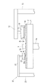
図1は、本発明に係る研磨パッドのコンディショニング装置を備えた研磨装置の全体構成を示す模式図である。図1に示すように、研磨装置は、研磨テーブル1と、研磨対象物である半導体ウエハ等の基板Wを保持して研磨テーブル上の研磨パッドに押圧するトップリング10とを備えている。研磨テーブル1は、テーブル軸1aを介してその下方に配置される研磨テーブル回転モータ(図示せず)に連結されており、テーブル軸1aの回りに回転可能になっている。研磨テーブル1の上面には研磨パッド2が貼付されており、研磨パッド2の表面が基板Wを研磨する研磨面2aを構成している。研磨パッド2には、ダウケミカル社(Dow Chemical Company)製のSUBA800、IC1000、IC1000/SUBA400(二層クロス)等が用いられている。SUBA800は繊維をウレタン樹脂で固めた不織布である。IC1000は硬質の発泡ポリウレタンであり、その表面に多数の微細な孔(ポア)を有したパッドであり、パーフォレートパッドとも呼ばれている。研磨テーブル1の上方には供給ノズル3が設置されており、この供給ノズル3によって研磨テーブル1上の研磨パッド2に研磨液(スラリ)が供給されるようになっている。
FIG. 1 is a schematic diagram showing the overall configuration of a polishing apparatus provided with a polishing pad conditioning apparatus according to the present invention. As shown in FIG. 1, the polishing apparatus includes a polishing table 1 and a
トップリング10は、トップリングシャフト11に接続されており、トップリングシャフト11は、トップリングヘッド12に対して上下動するようになっている。トップリングシャフト11の上下動により、トップリングヘッド12に対してトップリング10の全体を上下動させ位置決めするようになっている。トップリングシャフト11は、トップリング回転モータ(図示せず)の駆動により回転するようになっている。トップリングシャフト11の回転により、トップリング10がトップリングシャフト11の回りに回転するようになっている。
The
トップリング10は、その下面に半導体ウエハなどの基板Wを保持できるようになっている。トップリングヘッド12はトップリングヘッドシャフト13を中心として旋回可能に構成されており、下面に基板Wを保持したトップリング10は、トップリングヘッド12の旋回により基板の受取位置から研磨テーブル1の上方に移動可能になっている。トップリング10は、下面に基板Wを保持して基板Wを研磨パッド2の表面(研磨面)に押圧する。このとき、研磨テーブル1およびトップリング10をそれぞれ回転させ、研磨テーブル1の上方に設けられた研磨液供給ノズル3から研磨パッド2上に研磨液を供給する。研磨液には砥粒としてシリカ(SiO2)やセリア(CeO2)等を含んだ研磨液が用いられる。このように、研磨液を研磨パッド2上に供給しつつ、基板Wを研磨パッド2に押圧して基板Wと研磨パッド2とを相対移動させて基板上の絶縁膜や金属膜等を研磨する。絶縁膜としてはSiO2が挙げられる。金属膜としてはCu膜、W膜、Ta膜、Ti膜が挙げられる。
The
図1に示すように、研磨装置は、研磨パッド2をドレッシングするドレッシング装置20を備えている。ドレッシング装置20は、ドレッサアーム21と、ドレッサアーム21の先端に回転自在に取り付けられたドレッサ22と、ドレッサアーム21の他端に連結される揺動軸23とを備えている。ドレッサ22の下部はドレッシング部材22aにより構成され、ドレッシング部材22aは円形のドレッシング面を有しており、ドレッシング面には硬質な砥粒が電着等により固定されている。この硬質な砥粒としては、ダイアモンド砥粒やセラミック砥粒などが挙げられる。ドレッサ22は、図示しないモータによって回転するようになっている。揺動軸23は図示しないモータによって回転し、揺動軸23を中心にドレッサアーム21を揺動させてドレッサ22を揺動させるようになっている。
As shown in FIG. 1, the polishing apparatus includes a
本発明者らは、図1に示すようなドレッサ22を用いて研磨パッド2のドレッシングを行うことにより、以下のような知見を得たものである。
研磨パッドは、温度により弾性率が変わる。すなわち、研磨パッドは、温度が高いと弾性率が大きくなり、温度が低いと弾性率が小さくなる。研磨パッドの弾性率は、研磨パッドをドレッシングした時の研磨パッドの表面粗さに影響を及ぼす。
The inventors have obtained the following knowledge by dressing the
The elastic modulus of the polishing pad varies depending on the temperature. That is, the elastic modulus of the polishing pad increases when the temperature is high, and decreases when the temperature is low. The elastic modulus of the polishing pad affects the surface roughness of the polishing pad when the polishing pad is dressed.
1)研磨パッドの弾性率が小さい場合
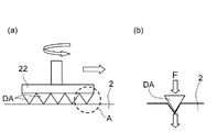
図2(a)は、下面にダイアモンド砥粒DAを備えたドレッサ22によって研磨パッド2をドレッシングしている状態を示す模式図であり、図2(b)は、図2(a)のA部の拡大図である。図2(a),(b)ではダイアモンド砥粒DAは拡大して図示している。図2(a)の矢印で示すように、ドレッシング中、ドレッサ22は軸心の回りに回転しつつ研磨パッド2の表面に沿って移動する。ドレッシングの際にダイアモンド砥粒DAは、図2(b)に示すように、ドレッサ荷重により研磨パッド2の表面に喰い込む。このとき、研磨パッドの弾性率が小さい場合、研磨パッドが硬く、ドレッサ22のダイアモンド砥粒DAが研磨パッド2を押す力が逃げず、ダイアモンド砥粒DAで押しつける力を研磨パッド2がきちんと受ける。図2(b)において、ダイアモンド砥粒DAが研磨パッド2を押す力は実線矢印Fで示し、この力Fを研磨パッド2が実線矢印で示すようにきちんと受ける。したがって、砥粒は、荷重をかけた分、研磨パッド2を削り取ることになり、研磨パッド2の表面粗さは粗くなる傾向にある。
1) When the elastic modulus of the polishing pad is small FIG. 2A is a schematic diagram showing a state in which the
2)研磨パッドの弾性率が大きい場合
図3(a),(b)は、研磨パッドの弾性率が大きい場合における研磨パッドとダイアモンド砥粒DAとの関係を示す図である。図3(a)は、図2(a)のA部の拡大図であり、図3(b)は、図3(a)に示すダイアモンド砥粒DAに隣接したダイアモンド砥粒DAを追加して示す拡大図である。
研磨パッドの弾性率が大きい場合、研磨パッドが軟らかく、図3(a)に示すように、ダイアモンド砥粒DAが研磨パッド2を押す力が左右に逃げてしまい、ダイアモンド砥粒DAで押しつける力を研磨パッド2で十分に受けない。図3(a)において、ダイアモンド砥粒DAが研磨パッド2を押す力は実線矢印Fで示し、この力Fを研磨パッド2が実線矢印で示すように受けるが、一部の力が点線矢印で示すように逃げる。したがって、砥粒は、研磨パッド2を削りにくく、研磨パッド2の表面粗さは細かくなる傾向にある。そして、図3(b)のB部に示すように、隣接する砥粒間の研磨パッド2の盛り上がりにより、研磨パッド2の削られ方に影響があり、この点からも研磨パッド2の表面粗さは細かくなる傾向にある。
2) When the Elastic Modulus of the Polishing Pad is Large FIGS. 3A and 3B are diagrams showing the relationship between the polishing pad and the diamond abrasive grains DA when the elastic modulus of the polishing pad is large. FIG. 3A is an enlarged view of part A of FIG. 2A, and FIG. 3B is obtained by adding diamond abrasive grains DA adjacent to the diamond abrasive grains DA shown in FIG. 3A. It is an enlarged view shown.
When the elastic modulus of the polishing pad is large, the polishing pad is soft, and as shown in FIG. 3A, the force that the diamond abrasive grain DA pushes the
上記1)および2)から分かるように、研磨パッドの弾性率によって、ドレッシングした時の研磨パッドの削られ方が異なり、その結果、研磨パッドの表面粗さが異なってくる。また、上述したように、研磨パッドの弾性率は温度によって異なり、温度が高いと弾性率が大きくなり、温度が低いと弾性率が小さくなる。このように、ドレッシング時における研磨パッドの温度と、ドレッシングされた研磨パッドの表面粗さとの間には、相関関係があることが分かる。 As can be seen from the above 1) and 2), how the polishing pad is shaved when dressing differs depending on the elastic modulus of the polishing pad, and as a result, the surface roughness of the polishing pad varies. Further, as described above, the elastic modulus of the polishing pad varies depending on the temperature. When the temperature is high, the elastic modulus increases. When the temperature is low, the elastic modulus decreases. Thus, it can be seen that there is a correlation between the temperature of the polishing pad during dressing and the surface roughness of the dressed polishing pad.
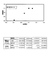
次に、研磨パッドの表面粗さと研磨性能(研磨速度)の関係を図4に示す。
図4は、表面粗さの算術平均粗さ(Ra)と研磨速度(RR)との関係を示す測定データの表及びグラフである。研磨速度の単位はnm/minである。図4のグラフに示すデータは、表面粗さと研磨速度の相関係数が0.96となる強い相関関係を示す研磨パッド領域を選択して表面粗さを求めた場合のデータである。図4の表に示すデータは、4種類の研磨速度で研磨するときの、研磨パッド表面の表面粗さ及び標準化した表面粗さである。図4から明らかなように研磨パッドの表面粗さが大きくなるほど研磨速度が向上し、表面粗さが1.1の付近で研磨速度は最大値をとっている。このように研磨パッドの表面粗さは、研磨性能と強い関連性を示すことが分かる。
Next, FIG. 4 shows the relationship between the surface roughness of the polishing pad and the polishing performance (polishing rate).
FIG. 4 is a measurement data table and graph showing the relationship between the arithmetic average roughness (Ra) of the surface roughness and the polishing rate (RR). The unit of the polishing rate is nm / min. The data shown in the graph of FIG. 4 is data when the surface roughness is obtained by selecting a polishing pad region showing a strong correlation in which the correlation coefficient between the surface roughness and the polishing rate is 0.96. The data shown in the table of FIG. 4 is the surface roughness and standardized surface roughness of the polishing pad surface when polishing at four different polishing rates. As is apparent from FIG. 4, the polishing rate increases as the surface roughness of the polishing pad increases, and the polishing rate takes the maximum value when the surface roughness is near 1.1. Thus, it can be seen that the surface roughness of the polishing pad is strongly related to the polishing performance.
上述したように、研磨パッドの表面粗さは表面温度及び研磨性能と相関関係を有しているため、研磨パッドの表面粗さと研磨パッドの表面温度との関係と、研磨パッドの表面粗さと研磨性能との関係とから、所望の研磨性能に対応するドレッシング時の研磨パッドの表面温度を求めることができる。
具体的には、達成したい研磨性能があるときにその研磨性能に対応する研磨パッドの表面粗さ(目標)を求め、その求めた表面粗さに対応する研磨パッドの表面温度になるように温度調整しながら、そのパッド温度とパッド表面粗さに対するドレッシング条件で研磨パッドをドレッシングする。ドレッシング中、研磨パッドの表面粗さをモニターし、研磨パッドの表面粗さが目標表面粗さに到達したら、ドレッシング終了とする。一定時間経過しても研磨パッドの表面粗さが目標表面粗さにならない場合には、目標表面粗さとモニターした表面粗さ(または測定した表面粗さ)とを比較し、目標表面粗さとモニターした表面粗さの差に基づいて研磨パッド温度を上げるか、または研磨パッド温度を下げるように調整する。
As described above, since the surface roughness of the polishing pad has a correlation with the surface temperature and the polishing performance, the relationship between the surface roughness of the polishing pad and the surface temperature of the polishing pad, the surface roughness of the polishing pad, and the polishing From the relationship with the performance, the surface temperature of the polishing pad at the time of dressing corresponding to the desired polishing performance can be obtained.
Specifically, when there is a polishing performance that is desired to be achieved, the surface roughness (target) of the polishing pad corresponding to the polishing performance is obtained, and the surface temperature of the polishing pad corresponding to the obtained surface roughness is obtained. While adjusting, the polishing pad is dressed under dressing conditions for the pad temperature and pad surface roughness. During the dressing, the surface roughness of the polishing pad is monitored, and when the surface roughness of the polishing pad reaches the target surface roughness, the dressing is finished. If the surface roughness of the polishing pad does not reach the target surface roughness after a certain period of time, the target surface roughness is compared with the monitored surface roughness (or measured surface roughness), and the target surface roughness is monitored. The polishing pad temperature is increased or adjusted to decrease based on the difference in surface roughness.
上記知見に基づいて、本発明は、研磨パッド2のドレッシング中に、研磨パッド2の表面粗さをモニターし、モニターした表面粗さに基づいて研磨パッド2の表面温度を調整しつつ、研磨パッド2のドレッシングを行うようにしたものである。
そのため、本発明のコンディショニング装置は、ドレッシング装置20に加えて、研磨パッドの表面粗さを測定する測定ユニットおよび研磨パッドの温度を調整する温度調整ユニットを備えている。
Based on the above knowledge, the present invention monitors the surface roughness of the
Therefore, in addition to the
図5は、本発明のコンディショニング装置15を示す模式図である。図5に示すように、本発明のコンディショニング装置15は、ドレッシング装置20に加えて、研磨パッドの表面粗さ測定ユニット30および研磨パッドの温度調整ユニット40を備えている。
FIG. 5 is a schematic diagram showing the
図5に示すように、研磨パッドの表面粗さ測定ユニット(表面粗さ測定手段)30は、研磨パッド2にレーザ光を投光する投光部31と、投光部31から投光されて研磨パッド2の表面で反射散乱した光を受光する受光部32を備えている。受光部32は、CCDセンサ,CMOSセンサ等から構成されている。本実施形態においては、投光部31および受光部32はドレッシング装置20のドレッサアーム21に支持されており、ドレッサアーム21の揺動により、投光部31および受光部32は、研磨パッド2の上方で移動して研磨パッド2上の多数の箇所に光を投光し多数の箇所で反射散乱した光を受光するようになっている。受光部32は制御部60に接続されている。制御部60は、受光部32で受光した光を画像化して処理し研磨パッド2の表面粗さを算出するように構成されている。制御部60で得られるパッド表面粗さの指標は、算術平均粗さ;Ra、二乗平均平方根粗さ;Rq、粗さ曲線の最大谷深さ;Rv、粗さ曲線の最大山高さ;Rp、最大高さ粗さ;Rzが挙げられる。これらパッド表面粗さの指標は研磨性能(研磨レート)と強い関連性を示す指標である。研磨パッドの表面粗さ測定ユニット30および制御部60は、ドレッサ22による研磨パッド2のドレッシング中に、上記指標で表される表面粗さを測定し、測定値をモニター(監視)するように構成されている。研磨パッドの表面粗さ測定ユニット30は、研磨テーブル1の回転方向に対して、ドレッサ22の下流側の箇所を測定する位置に配置することが好ましい。この配置により、研磨パッドの表面粗さ測定ユニット30は、ドレッサ22によりドレッシングされた直後の箇所における研磨パッド2の表面粗さを測定することが可能になる。
As shown in FIG. 5, the polishing pad surface roughness measuring unit (surface roughness measuring means) 30 is projected from the
図5に示すように、研磨パッドの温度調整ユニット(温度調整手段)40は、研磨パッド2の表面に接触するパッド接触部材41と、研磨パッド2の表面温度を非接触で測定するサーモグラフ又は放射温度計44と、パッド接触部材41に温度調整された液体を供給する液体供給システム45とを備えている。パッド接触部材41は、内部に熱媒体としての液体が流れる流路を有し、下面が研磨パッド2の表面に接触して研磨パッド2を加熱又は冷却するように構成されている。パッド接触部材41は、支持アーム42を介して支持軸43により支持されている。パッド接触部材41は、研磨パッド2と接触する接触位置と該接触位置の上方の上昇位置との間で昇降可能に構成されるとともに、研磨テーブル1の半径方向に移動可能に構成されている。
As shown in FIG. 5, the polishing pad temperature adjustment unit (temperature adjustment means) 40 includes a
液体供給システム45は、液体供給タンク46と、液体供給タンク46とパッド接触部材41とを連結する供給ライン47および戻りライン48とを備えている。熱媒体としての液体は、液体供給タンク46から供給ライン47を通じてパッド接触部材41に供給され、パッド接触部材41から戻りライン48を通じて液体供給タンク46に戻される。このように、液体は、液体供給タンク46とパッド接触部材41との間を循環する。液体供給タンク46は、液体を加熱するヒータ(図示せず)を備えており、液体はヒータにより所定の温度に加熱される。すなわち、液体供給タンク46は温調機として機能する。
The
液体供給システム45は、さらに、供給ライン47を流れる液体の流量を調整する流量調整弁50と、流量調整弁50を制御する温調コントローラ51とを備えている。なお、供給ライン47には冷水ライン54が接続され、冷水ライン54から供給ライン47に冷水が供給可能になっている。冷水ライン54には工場のユーティリティ又はチラーから冷水が供給されるようになっている。また、戻りライン48には排水ライン55が接続され、戻りライン48を流れる液体を排水可能になっている。
The
サーモグラフ又は放射温度計44は、研磨パッド2の表面温度を測定し、その測定値を制御部60に送信するようになっている。制御部60は、研磨パッドの表面粗さ測定ユニット30により測定された研磨パッド2の表面粗さ(測定表面粗さ)と、予め設定された目標とする研磨パッドの表面粗さ(目標表面粗さ)とを比較し、粗さの比較結果と、サーモグラフ又は放射温度計44で測定された研磨パッド2の表面温度(測定表面温度)とから研磨パッド2の制御されるべき表面温度(制御目標温度)を演算する。制御部60は、演算した研磨パッド2の制御目標温度を温調コントローラ51に送信する。温調コントローラ51は研磨パッド2の制御目標温度に基づいて流量調整弁50を制御し、パッド接触部材41に供給される液体の流量を制御する。研磨パッド2の表面温度は、パッド接触部材41を流れる液体と研磨パッド2との間での熱交換により調整される。
The thermograph or
研磨パッド2の表面温度は、パッド接触部材41に供給される、温度制御された液体の流量を調整することにより制御される。パッド接触部材41に供給される液体(熱媒体)としては、水が使用される。水の温度は、液体供給タンク46のヒータにより、例えば約80℃に加熱されて温水とされる。パッド接触部材41に温水と冷水とを切替えて供給可能とするために、供給ライン47,戻りライン48,冷水ライン54,排水ライン55にはバルブV1〜V4が設けられている。すなわち、供給ライン47にはバルブV1が設置されており、温水はバルブV1を介してパッド接触部材41に供給されるようになっている。冷水ライン54にはバルブV2が設置されており、冷水はバルブV2を介してパッド接触部材41に供給されるようになっている。戻りライン48には、バルブV3が設置されており、パッド接触部材41に供給された温水はバルブV3を介して液体供給タンク46に戻るようになっている。戻りライン48を流れる冷水はバルブV4を介して排水可能になっている。パッド接触部材41に温水を供給する際には、バルブV1,V3を開、バルブV2,V4を閉とする。パッド接触部材41に冷水を供給する際には、バルブV1,V3を閉、バルブV2,V4を開とする。
The surface temperature of the
次に、図5に示すように構成されたコンディショニング装置15の動作を説明する。
制御部60には、CMPプロセスにより定まる目標となる研磨パッドの表面粗さ(目標表面粗さ)が予め設定されている。また、ドレッシング条件として、ドレッサ荷重、ドレッサ回転速度、ドレッシング時間、研磨テーブルの回転速度、を一定とし、研磨パッドの温度を変えてドレッシングをし、その時の研磨パッドの表面粗さを測定することにより、研磨パッドの表面粗さと研磨パッドの温度との関係を予め求めておき、この求めた研磨パッドの表面粗さと研磨パッドの温度との関係を制御部60に蓄積させてある。なお、ドレッサの揺動速度を一定とするというドレッシング条件を加えてもよい。この関係はテーブルの形式等で蓄積させてある。
Next, the operation of the
In the
コンディショニング装置15は、1枚の基板又は所定枚数の基板を研磨した後などのように、研磨パッド2のドレッシングが必要になったときに動作を開始し、ドレッサ22による研磨パッド2のドレッシングを開始するとともに研磨パッドの温度調整ユニット40による研磨パッド2の表面温度の調整を開始する。ドレッシング工程中、供給ノズル3からドレッシング液として、例えば、純水(DIW)を研磨パッド2に供給する。そして、ドレッサ22による研磨パッド2のドレッシング工程中、研磨パッドの表面粗さ測定ユニット30の投光部31から研磨パッド2にレーザ光を投光し研磨パッド2で反射散乱した光を受光部32で受光し、受光部32で受光した光を制御部60で画像化して処理し、研磨パッド2の表面粗さを算出する。制御部60で得られるパッド表面粗さの指標は、研磨性能(研磨レート)と相関のある指標であって、算術平均粗さ;Ra、二乗平均平方根粗さ;Rq、粗さ曲線の最大谷深さ;Rv、粗さ曲線の最大山高さ;Rp、最大高さ粗さ;Rzが挙げられる。制御部60は、これら5つの指標のうち少なくとも一つの指標を得る。
The
ドレッシング工程中、制御部60には、サーモグラフ又は放射温度計44から研磨パッド2の表面温度(測定表面温度)が入力される。制御部60は、研磨パッドの表面粗さ測定ユニット30により測定された研磨パッド2の表面粗さ(測定表面粗さ)と、予め設定された目標とする研磨パッドの表面粗さ(目標表面粗さ)とを比較し、粗さの比較結果と、サーモグラフ又は放射温度計44で測定された研磨パッド2の表面温度(測定表面温度)とから研磨パッド2の制御されるべき表面温度(制御目標温度)を演算する。制御部60は、演算した研磨パッド2の制御目標温度を温調コントローラ51に送信する。温調コントローラ51は研磨パッド2の制御目標温度に基づいて流量調整弁50を制御し、研磨パッドの表面温度を制御する。
During the dressing process, the surface temperature (measured surface temperature) of the
より具体的には、制御部60は、測定表面粗さと目標表面粗さとを比較し、測定表面粗さの方が目標表面粗さより大きい場合には、研磨パッド2の測定表面温度より高い制御目標温度を温調コントローラ51に送信し、測定表面粗さの方が目標表面粗さより小さい場合には、研磨パッド2の測定表面温度より低い制御目標温度を温調コントローラ51に送信する。温調コントローラ51は研磨パッド2の制御目標温度に基づいて流量調整弁50を制御し、研磨パッドの表面温度を制御する。研磨パッド2の表面温度は、パッド接触部材41に供給される温水又は冷水の流量を流量調整弁50により制御することにより、所望の値に制御することができる。
More specifically, the
このように、研磨パッド2のドレッシング中に、研磨パッド2の表面粗さをモニターし、モニターした表面粗さに基づいて研磨パッド2の表面温度を調整しつつ、研磨パッド2のドレッシングを行う。表面粗さのモニターにより、測定表面粗さの方が目標表面粗さより大きい場合には、研磨パッド2の表面温度を測定表面温度より上げて研磨パッド2の弾性率を大きくし、ドレッサ22により形成される研磨パッド2の表面粗さが細かくなるように制御する。逆に、測定表面粗さの方が目標表面粗さより小さい場合には、研磨パッド2の表面温度を測定表面温度より下げて研磨パッド2の弾性率を小さくし、ドレッサ22により形成される研磨パッド2の表面粗さが粗くなるように制御する。
In this way, during the dressing of the
図5においては、研磨パッドの温度調整ユニット40として、温水又は冷水をパッド接触部材41に供給し、パッド接触部材41の下面を研磨パッド2の表面に接触させることにより研磨パッド2の表面温度を制御するユニットを図示したが、温度制御された流体を研磨パッド2の表面に吹き付ける少なくとも1つのノズルを備えた研磨パッドの温度調整ユニット(温度調整手段)としてもよい。また、ドレッシング時に供給ノズル3から研磨パッド2に供給されるドレッシング液(例えば、純水)を所定の温度に制御するようにした研磨パッドの温度調整ユニット(温度調整手段)としてもよい。
In FIG. 5, as the
図6は、本発明のコンディショニング装置15の第2の態様を示す模式図である。第2の態様におけるコンディショニング装置15がドレッシング装置20、研磨パッドの表面粗さ測定ユニット30、研磨パッドの温度調整ユニット40および制御部60で構成されることは、第1の態様のコンディショニング装置15と同様であるが、第2の態様においては、研磨パッドの温度調整ユニット40は、2つのパッド接触部材41−1,41−2と、2つのサーモグラフ又は放射温度計44−1,44−2とを備えている。パッド接触部材41−1は支持アーム42−1を介して支持軸43−1により支持されている。パッド接触部材41−2は支持アーム42−2を介して支持軸43−2により支持されている。
FIG. 6 is a schematic view showing a second aspect of the
パッド接触部材41−1およびパッド接触部材41−2に液体を供給する液体供給タンク46は、1台であり、1台の液体供給タンク46から流量調整弁50−1,50−2を介して温度制御された液体をパッド接触部材41−1,41−2に個別に供給することができるようになっている。また、図示していない冷水ラインからパッド接触部材41−1,41−2に個別に温度制御された冷水を供給できるようになっている。なお、バルブ類は図示を省略している。第2の態様のその他の構成は、第1の態様と同様である。
There is one
図6に示すように構成されたコンディショニング装置15によれば、ドレッシング中に2つのパッド接触部材41−1,41−2により研磨パッド2の半径方向の異なった領域毎に温度調整を行うことができ、したがって、研磨パッド2の半径方向に表面粗さを変えることができる。このように、研磨パッド2の半径方向に表面粗さが異なる領域を形成することにより、基板の研磨プロファイルの調整ができる。
According to the
図7は、図6に示すコンディショニング装置15によりコンディショニングされた研磨パッドを示す図であり、研磨パッドの半径方向内側の領域と外側の領域とで表面粗さが異なる状態を示す平面図である。図7に示すように、研磨パッド2の半径方向内側の領域2Aの表面粗さは粗く、外側の領域2Bの表面粗さは細かい。
FIG. 7 is a view showing the polishing pad conditioned by the
図8は、本発明に係る研磨パッドのコンディショニング方法の手順を示すフローチャートである。図8に示すように、ドレッシング装置20による研磨パッド2のドレッシングを開始するとともに研磨パッドの温度調整ユニット40による研磨パッド2の表面温度の調整を開始する。なお、先に研磨パッドの温度調整ユニット40による研磨パッド2の表面温度の調整を開始し、研磨パッド2の表面温度が予め定めた温度に達したら、ドレッサ22によるドレッシングを開始してもよい。レシピで入力した研磨パッドの温度に到達したら、研磨パッドの表面粗さ測定ユニット30による研磨パッド2の表面粗さの測定結果を制御部60へ送信する。研磨パッドの表面粗さ測定ユニット30により研磨パッド2の表面粗さを測定する際には、ドレッサ22を研磨パッド2に押し当てて研磨テーブル1を回転させるか、又は、ドレッサ22を研磨パッド2から離して研磨テーブル1の回転を止める。
FIG. 8 is a flowchart showing a procedure of a polishing pad conditioning method according to the present invention. As shown in FIG. 8, dressing of the
次に、制御部60において、測定表面粗さと予め設定された目標表面粗さとを比較して表面粗さの判定を行う。測定表面粗さが目標表面粗さに等しい場合には、研磨パッド2のドレッシングを終了するとともに研磨パッド2の表面温度の調整を終了する。測定表面粗さが目標表面粗さに等しくない場合には、ドレッシングを行いながら、目標表面粗さとなるように温調コントローラ51で研磨パッド2の表面温度を制御する。このように、ドレッシングを行いながら目標表面粗さとなるように研磨パッド2の表面温度を制御する表面粗さモニターを継続して行い、測定表面粗さが目標表面粗さに到達したら、研磨パッド2のドレッシングを終了するとともに研磨パッド2の表面温度の調整を終了する。
Next, the
これまで本発明の実施形態について説明したが、本発明は上述の実施形態に限定されず、その技術思想の範囲内において、種々の異なる形態で実施されてよいことは勿論である。 Although the embodiment of the present invention has been described so far, the present invention is not limited to the above-described embodiment, and it is needless to say that the present invention may be implemented in various different forms within the scope of the technical idea.
1 研磨テーブル
1a テーブル軸
2 研磨パッド
2a 研磨面
3 供給ノズル
10 トップリング
11 トップリングシャフト
12 トップリングヘッド
13 トップリングヘッドシャフト
15 コンディショニング装置
20 ドレッシング装置
21 ドレッサアーム
22 ドレッサ
22a ドレッシング部材
23 揺動軸
30 研磨パッドの表面粗さ測定ユニット
31 投光部
32 受光部
40 研磨パッドの温度調整ユニット
41,41−1,41−2 パッド接触部材
42,42−1,42−2 支持アーム
43,43−1,43−2 支持軸
44,44−1,44−2 サーモグラフ又は放射温度計
45 液体供給システム
46 液体供給タンク
47 供給ライン
48 戻りライン
50,50−1,50−2 流量調整弁
51 温調コントローラ
54 冷水ライン
55 排水ライン
60 制御部
DESCRIPTION OF SYMBOLS 1 Polishing table
Claims (23)
前記研磨パッドのドレッシング中に、算術平均粗さ(Ra),二乗平均平方根粗さ(Rq),粗さ曲線の最大谷深さ(Rv),粗さ曲線の最大山高さ(Rp)および最大高さ粗さ(Rz)の5つの指標のうち少なくとも1つの指標で表される研磨パッドの表面粗さを測定し、測定された表面粗さと予め設定された目標表面粗さとを比較し、比較結果に基づいて前記研磨パッドを加熱又は冷却することにより研磨パッドの表面温度を調整することを特徴とする研磨パッドのコンディショニング方法。 A polishing pad conditioning method for adjusting a surface roughness of a polishing pad by dressing by pressing a dresser against a polishing pad on a polishing table for polishing a substrate,
During dressing of the polishing pad, arithmetic mean roughness (Ra), root mean square roughness (Rq), maximum valley depth (Rv) of the roughness curve, maximum peak height (Rp) and maximum height of the roughness curve The surface roughness of the polishing pad represented by at least one of the five indices of roughness roughness (Rz) is measured, the measured surface roughness is compared with a preset target surface roughness, and the comparison result A polishing pad conditioning method comprising adjusting the surface temperature of the polishing pad by heating or cooling the polishing pad based on the above.
前記研磨パッドのドレッシング中に、算術平均粗さ(Ra),二乗平均平方根粗さ(R
q),粗さ曲線の最大谷深さ(Rv),粗さ曲線の最大山高さ(Rp)および最大高さ粗
さ(Rz)の5つの指標のうち少なくとも1つの指標で表される研磨パッドの表面粗さをモニターし、
前記研磨パッドのドレッシング中に、前記研磨パッドの表面温度を所定の温度に調整することを特徴とする研磨パッドのコンディショニング方法。 A polishing pad conditioning method for adjusting a surface roughness of a polishing pad by dressing by pressing a dresser against a polishing pad on a polishing table for polishing a substrate,
Arithmetic mean roughness (Ra), root mean square roughness (R) during dressing of the polishing pad
q), polishing pad represented by at least one of the five indices of maximum valley depth (Rv), maximum peak height (Rp) and maximum height roughness (Rz) of the roughness curve Monitor the surface roughness of
A polishing pad conditioning method, wherein a surface temperature of the polishing pad is adjusted to a predetermined temperature during dressing of the polishing pad.
前記研磨パッドのドレッシング中に、前記研磨パッドの表面温度を所定の温度に調整し、
前記研磨パッド上に、研磨パッドの半径方向に複数のエリアを定義し、エリア毎に異なる温度に調整して、ドレッシングを行うことを特徴とする研磨パッドのコンディショニング方法。 A polishing pad conditioning method for adjusting a surface roughness of a polishing pad by dressing by pressing a dresser against a polishing pad on a polishing table for polishing a substrate,
During dressing of the polishing pad, the surface temperature of the polishing pad is adjusted to a predetermined temperature,
A polishing pad conditioning method comprising: performing a dressing by defining a plurality of areas in the radial direction of the polishing pad on the polishing pad and adjusting the temperature to a different temperature for each area.
ドレッサにより前記研磨パッドをドレッシングし、
前記研磨パッドの表面粗さを測定し、
前記測定して得られた前記研磨パッドの表面粗さと、予め設定した目標表面粗さとを比較し、
前記研磨パッドのドレッシング中に、前記比較した結果に基づいて、前記研磨パッドの表面温度を所定の温度に調整し、
前記研磨パッド上に、研磨パッドの半径方向に複数のエリアを定義し、エリア毎に異なる温度に調整して、ドレッシングを行うことを特徴とする研磨パッドのコンディショニング方法。 A polishing pad conditioning method for adjusting a surface roughness of a polishing pad on a polishing table for polishing a substrate,
Dressing the polishing pad with a dresser,
Measure the surface roughness of the polishing pad,
The surface roughness of the polishing pad obtained by the measurement is compared with a preset target surface roughness,
During dressing of the polishing pad, based on the comparison result, the surface temperature of the polishing pad is adjusted to a predetermined temperature,
A polishing pad conditioning method comprising: performing a dressing by defining a plurality of areas in the radial direction of the polishing pad on the polishing pad and adjusting the temperature to a different temperature for each area.
前記研磨パッドに押し当てて研磨パッドのドレッシングを行うドレッサと、該ドレッサを回転させるとともに研磨パッドの表面に沿って移動させる機構とを備えたドレッシング装置と、
前記研磨パッドの表面粗さを測定する研磨パッドの表面粗さ測定手段と、
前記研磨パッドの表面温度を調整する研磨パッドの温度調整手段と、
前記ドレッシング装置、前記研磨パッドの表面粗さ測定手段および前記研磨パッドの表面温度調整手段を制御する制御部とを備え、
前記研磨パッドの表面粗さ測定手段により、前記研磨パッドのドレッシング中に、算術平均粗さ(Ra),二乗平均平方根粗さ(Rq),粗さ曲線の最大谷深さ(Rv),粗さ曲線の最大山高さ(Rp)および最大高さ粗さ(Rz)の5つの指標のうち少なくとも1つの指標で表される研磨パッドの表面粗さを測定することを特徴とする研磨パッドのコンディショニング装置。 A polishing pad conditioning apparatus for adjusting a surface roughness of a polishing pad by dressing a polishing pad on a polishing table for polishing a substrate,
A dressing device comprising: a dresser that presses against the polishing pad to dress the polishing pad; and a mechanism that rotates the dresser and moves the dresser along the surface of the polishing pad;
A polishing pad surface roughness measuring means for measuring the surface roughness of the polishing pad;
Polishing pad temperature adjusting means for adjusting the surface temperature of the polishing pad;
A controller for controlling the dressing device, the surface roughness measuring means of the polishing pad and the surface temperature adjusting means of the polishing pad;
During the polishing pad dressing, the arithmetic average roughness (Ra), the root mean square roughness (Rq), the maximum valley depth (Rv) of the roughness curve, and the roughness are measured by the polishing pad surface roughness measuring means. A polishing pad conditioning apparatus for measuring a surface roughness of a polishing pad represented by at least one of five indices of maximum peak height (Rp) and maximum height roughness (Rz) of a curve .
前記2つ以上のパッド接触部材又は前記ノズルは、各々独立して研磨パッドの表面温度を調整可能であることを特徴とする請求項18に記載の研磨パッドのコンディショニング装置。 Two or more pad contact members or nozzles are installed in the radial direction of the polishing pad,
19. The polishing pad conditioning apparatus according to claim 18 , wherein the two or more pad contact members or the nozzles can independently adjust the surface temperature of the polishing pad.
請求項15乃至22のいずれか一項に記載の研磨パッドのコンディショニング装置を備えたことを特徴とする研磨装置。 A polishing table to which the polishing pad is attached;
A polishing apparatus comprising the polishing pad conditioning apparatus according to any one of claims 15 to 22 .
Priority Applications (5)
| Application Number | Priority Date | Filing Date | Title |
|---|---|---|---|
| JP2014030998A JP6340205B2 (en) | 2014-02-20 | 2014-02-20 | Polishing pad conditioning method and apparatus |
| TW104104535A TWI649159B (en) | 2014-02-20 | 2015-02-11 | Method and apparatus for conditioning polishing pad |
| KR1020150021693A KR102179092B1 (en) | 2014-02-20 | 2015-02-12 | Method and apparatus for conditioning polishing pad |
| CN201510080294.8A CN104858785B (en) | 2014-02-20 | 2015-02-13 | The dressing method and device of grinding pad |
| US14/624,820 US9731401B2 (en) | 2014-02-20 | 2015-02-18 | Method and apparatus for conditioning polishing pad |
Applications Claiming Priority (1)
| Application Number | Priority Date | Filing Date | Title |
|---|---|---|---|
| JP2014030998A JP6340205B2 (en) | 2014-02-20 | 2014-02-20 | Polishing pad conditioning method and apparatus |
Publications (3)
| Publication Number | Publication Date |
|---|---|
| JP2015155128A JP2015155128A (en) | 2015-08-27 |
| JP2015155128A5 JP2015155128A5 (en) | 2016-11-24 |
| JP6340205B2 true JP6340205B2 (en) | 2018-06-06 |
Family
ID=53797295
Family Applications (1)
| Application Number | Title | Priority Date | Filing Date |
|---|---|---|---|
| JP2014030998A Active JP6340205B2 (en) | 2014-02-20 | 2014-02-20 | Polishing pad conditioning method and apparatus |
Country Status (5)
| Country | Link |
|---|---|
| US (1) | US9731401B2 (en) |
| JP (1) | JP6340205B2 (en) |
| KR (1) | KR102179092B1 (en) |
| CN (1) | CN104858785B (en) |
| TW (1) | TWI649159B (en) |
Families Citing this family (18)
| Publication number | Priority date | Publication date | Assignee | Title |
|---|---|---|---|---|
| JP6161999B2 (en) * | 2013-08-27 | 2017-07-12 | 株式会社荏原製作所 | Polishing method and polishing apparatus |
| JP2017121672A (en) * | 2016-01-05 | 2017-07-13 | 不二越機械工業株式会社 | Method for polishing workpiece and method for dressing polishing pad |
| US9865477B2 (en) * | 2016-02-24 | 2018-01-09 | Taiwan Semiconductor Manufacturing Co., Ltd. | Backside polisher with dry frontside design and method using the same |
| TWI582385B (en) * | 2016-05-06 | 2017-05-11 | 中華大學 | A polishing pad analyzing system and method thereof |
| JP6715153B2 (en) * | 2016-09-30 | 2020-07-01 | 株式会社荏原製作所 | Substrate polishing equipment |
| JP7023455B2 (en) * | 2017-01-23 | 2022-02-22 | 不二越機械工業株式会社 | Work polishing method and work polishing equipment |
| JP6923342B2 (en) * | 2017-04-11 | 2021-08-18 | 株式会社荏原製作所 | Polishing equipment and polishing method |
| US10350724B2 (en) * | 2017-07-31 | 2019-07-16 | Taiwan Semiconductor Manufacturing Company, Ltd. | Temperature control in chemical mechanical polish |
| CN107553330B (en) * | 2017-10-20 | 2019-07-12 | 德淮半导体有限公司 | Finishing disc system, chemical mechanical polishing device and conditioner discs fall off method for detecting |
| CN109702650A (en) * | 2017-10-26 | 2019-05-03 | 长鑫存储技术有限公司 | Grind pad dressing method, chemical and mechanical grinding method and device |
| CN109866108A (en) * | 2017-12-01 | 2019-06-11 | 咏巨科技有限公司 | Trimming device for polishing cushion and its manufacturing method and polishing pad finishing method |
| JP6975078B2 (en) | 2018-03-15 | 2021-12-01 | キオクシア株式会社 | Semiconductor manufacturing equipment and methods for manufacturing semiconductor equipment |
| KR102644395B1 (en) * | 2018-05-02 | 2024-03-08 | 주식회사 케이씨텍 | Pad assembly and conditioning device comprising the same |
| CN110549239A (en) * | 2018-05-31 | 2019-12-10 | 长鑫存储技术有限公司 | Chemical mechanical polishing device and polishing pad surface dressing method |
| JP7066599B2 (en) * | 2018-11-28 | 2022-05-13 | 株式会社荏原製作所 | Temperature control device and polishing device |
| JP7240931B2 (en) * | 2019-03-29 | 2023-03-16 | 株式会社荏原製作所 | Heat exchanger cleaning and polishing equipment |
| JP7406980B2 (en) * | 2019-12-24 | 2023-12-28 | 株式会社荏原製作所 | Polishing unit, substrate processing equipment, and polishing method |
| CN112405333B (en) * | 2020-12-04 | 2022-08-16 | 华海清科(北京)科技有限公司 | Chemical mechanical polishing device and polishing method |
Family Cites Families (18)
| Publication number | Priority date | Publication date | Assignee | Title |
|---|---|---|---|---|
| US5708506A (en) * | 1995-07-03 | 1998-01-13 | Applied Materials, Inc. | Apparatus and method for detecting surface roughness in a chemical polishing pad conditioning process |
| US5743784A (en) * | 1995-12-19 | 1998-04-28 | Applied Materials, Inc. | Apparatus and method to determine the coefficient of friction of a chemical mechanical polishing pad during a pad conditioning process and to use it to control the process |
| JPH09234663A (en) | 1996-02-28 | 1997-09-09 | Oki Electric Ind Co Ltd | Method and device for grinding wafer |
| JP2001223190A (en) * | 2000-02-08 | 2001-08-17 | Hitachi Ltd | Method and device for evaluating surface state of polishing pad, and method and device for manufacturing thin-film device |
| EP1361933A1 (en) * | 2001-02-20 | 2003-11-19 | Ebara Corporation | Polishing apparatus and dressing method |
| JP2003151934A (en) | 2001-11-15 | 2003-05-23 | Seiko Epson Corp | Cmp system and method of adjusting polishing pad for cmp |
| JP2003257914A (en) | 2002-02-27 | 2003-09-12 | Fujitsu Ltd | Method and apparatus for chemical-mechanical polishing, and manufacturing method of semiconductor device |
| JP2004186493A (en) * | 2002-12-04 | 2004-07-02 | Matsushita Electric Ind Co Ltd | Method and arrangement for chemomechanical polishing |
| JP2005347568A (en) * | 2004-06-03 | 2005-12-15 | Ebara Corp | Method and apparatus for polishing substrate |
| JP2005026453A (en) * | 2003-07-02 | 2005-01-27 | Ebara Corp | Substrate polishing apparatus and method therefor |
| JP4206318B2 (en) | 2003-09-17 | 2009-01-07 | 三洋電機株式会社 | Polishing pad dressing method and manufacturing apparatus |
| TWI284584B (en) * | 2005-05-09 | 2007-08-01 | Nat Univ Chung Cheng | Method for detecting the using condition and lifetime of the polish pad by sensing the temperature of the grinding interface during the chemical-mechanical polishing process |
| CN101796613B (en) * | 2007-09-14 | 2012-06-27 | 株式会社半导体能源研究所 | Semiconductor device and electronic appliance |
| US8292691B2 (en) * | 2008-09-29 | 2012-10-23 | Applied Materials, Inc. | Use of pad conditioning in temperature controlled CMP |
| US20110300776A1 (en) * | 2010-06-03 | 2011-12-08 | Applied Materials, Inc. | Tuning of polishing process in multi-carrier head per platen polishing station |
| CN202428310U (en) * | 2011-12-07 | 2012-09-12 | 有研半导体材料股份有限公司 | Heat-regulating polishing head for 300mm chemical mechanical polishing |
| JP2013172218A (en) | 2012-02-20 | 2013-09-02 | Sony Corp | Imaging device, image processing method, and program |
| JP6091773B2 (en) * | 2012-06-11 | 2017-03-08 | 株式会社東芝 | Manufacturing method of semiconductor device |
-
2014
- 2014-02-20 JP JP2014030998A patent/JP6340205B2/en active Active
-
2015
- 2015-02-11 TW TW104104535A patent/TWI649159B/en active
- 2015-02-12 KR KR1020150021693A patent/KR102179092B1/en active IP Right Grant
- 2015-02-13 CN CN201510080294.8A patent/CN104858785B/en active Active
- 2015-02-18 US US14/624,820 patent/US9731401B2/en active Active
Also Published As
| Publication number | Publication date |
|---|---|
| US20150231760A1 (en) | 2015-08-20 |
| CN104858785B (en) | 2019-01-11 |
| JP2015155128A (en) | 2015-08-27 |
| KR20150098574A (en) | 2015-08-28 |
| TW201532735A (en) | 2015-09-01 |
| KR102179092B1 (en) | 2020-11-16 |
| CN104858785A (en) | 2015-08-26 |
| US9731401B2 (en) | 2017-08-15 |
| TWI649159B (en) | 2019-02-01 |
Similar Documents
| Publication | Publication Date | Title |
|---|---|---|
| JP6340205B2 (en) | Polishing pad conditioning method and apparatus | |
| US10710208B2 (en) | Polishing method and polishing apparatus | |
| JP6010511B2 (en) | Method for measuring surface roughness of polishing pad | |
| US10259098B2 (en) | Method and apparatus for polishing a substrate | |
| US20230415296A1 (en) | Apparatus and method for cmp temperature control | |
| US20120190273A1 (en) | Polishing method and polishing apparatus | |
| JP6030720B2 (en) | Polishing apparatus and method | |
| JP2012525715A (en) | Temperature control for chemical mechanical polishing | |
| CN113874165B (en) | Chemical mechanical polishing equipment | |
| KR20190142338A (en) | Silicon Wafer Polishing Method | |
| US20230256562A1 (en) | Use of steam for pre-heating of cmp components | |
| JP2024509159A (en) | Temperature-controlled removal rate in CMP | |
| JP2022535701A (en) | Use of steam for preheating or cleaning CMP components |
Legal Events
| Date | Code | Title | Description |
|---|---|---|---|
| A521 | Request for written amendment filed |
Free format text: JAPANESE INTERMEDIATE CODE: A523 Effective date: 20161005 |
|
| A621 | Written request for application examination |
Free format text: JAPANESE INTERMEDIATE CODE: A621 Effective date: 20161005 |
|
| A977 | Report on retrieval |
Free format text: JAPANESE INTERMEDIATE CODE: A971007 Effective date: 20170724 |
|
| A131 | Notification of reasons for refusal |
Free format text: JAPANESE INTERMEDIATE CODE: A131 Effective date: 20170801 |
|
| A521 | Request for written amendment filed |
Free format text: JAPANESE INTERMEDIATE CODE: A523 Effective date: 20170906 |
|
| A131 | Notification of reasons for refusal |
Free format text: JAPANESE INTERMEDIATE CODE: A131 Effective date: 20171107 |
|
| A521 | Request for written amendment filed |
Free format text: JAPANESE INTERMEDIATE CODE: A523 Effective date: 20171130 |
|
| TRDD | Decision of grant or rejection written | ||
| A01 | Written decision to grant a patent or to grant a registration (utility model) |
Free format text: JAPANESE INTERMEDIATE CODE: A01 Effective date: 20180424 |
|
| A61 | First payment of annual fees (during grant procedure) |
Free format text: JAPANESE INTERMEDIATE CODE: A61 Effective date: 20180514 |
|
| R150 | Certificate of patent or registration of utility model |
Ref document number: 6340205 Country of ref document: JP Free format text: JAPANESE INTERMEDIATE CODE: R150 |
|
| R250 | Receipt of annual fees |
Free format text: JAPANESE INTERMEDIATE CODE: R250 |
|
| R250 | Receipt of annual fees |
Free format text: JAPANESE INTERMEDIATE CODE: R250 |
|
| R250 | Receipt of annual fees |
Free format text: JAPANESE INTERMEDIATE CODE: R250 |