JP6339179B2 - Switch strip, safety sensor strip and method for manufacturing the same, and prevention of pinching - Google Patents
Switch strip, safety sensor strip and method for manufacturing the same, and prevention of pinching Download PDFInfo
- Publication number
- JP6339179B2 JP6339179B2 JP2016513356A JP2016513356A JP6339179B2 JP 6339179 B2 JP6339179 B2 JP 6339179B2 JP 2016513356 A JP2016513356 A JP 2016513356A JP 2016513356 A JP2016513356 A JP 2016513356A JP 6339179 B2 JP6339179 B2 JP 6339179B2
- Authority
- JP
- Japan
- Prior art keywords
- strip
- switch strip
- switch
- electrode
- outer electrode
- Prior art date
- Legal status (The legal status is an assumption and is not a legal conclusion. Google has not performed a legal analysis and makes no representation as to the accuracy of the status listed.)
- Expired - Fee Related
Links
- 238000004519 manufacturing process Methods 0.000 title claims description 5
- 230000002265 prevention Effects 0.000 title description 5
- 238000000034 method Methods 0.000 title description 2
- 125000006850 spacer group Chemical group 0.000 claims description 47
- 239000012791 sliding layer Substances 0.000 claims description 20
- 229920002943 EPDM rubber Polymers 0.000 claims description 12
- 230000003313 weakening effect Effects 0.000 claims description 10
- 229920001971 elastomer Polymers 0.000 claims description 9
- 239000000806 elastomer Substances 0.000 claims description 9
- 239000003973 paint Substances 0.000 claims description 8
- 229920006342 thermoplastic vulcanizate Polymers 0.000 claims description 7
- 239000011888 foil Substances 0.000 claims description 6
- 229920002725 thermoplastic elastomer Polymers 0.000 claims description 6
- 239000002245 particle Substances 0.000 claims description 3
- 238000001125 extrusion Methods 0.000 claims 2
- 239000000853 adhesive Substances 0.000 description 13
- 230000001070 adhesive effect Effects 0.000 description 13
- RYGMFSIKBFXOCR-UHFFFAOYSA-N Copper Chemical compound [Cu] RYGMFSIKBFXOCR-UHFFFAOYSA-N 0.000 description 7
- 239000004020 conductor Substances 0.000 description 7
- OKTJSMMVPCPJKN-UHFFFAOYSA-N Carbon Chemical compound [C] OKTJSMMVPCPJKN-UHFFFAOYSA-N 0.000 description 6
- 229910052802 copper Inorganic materials 0.000 description 6
- 239000010949 copper Substances 0.000 description 6
- 230000008878 coupling Effects 0.000 description 6
- 238000010168 coupling process Methods 0.000 description 6
- 238000005859 coupling reaction Methods 0.000 description 6
- 229910002804 graphite Inorganic materials 0.000 description 6
- 239000010439 graphite Substances 0.000 description 6
- 239000003566 sealing material Substances 0.000 description 6
- 239000012790 adhesive layer Substances 0.000 description 5
- 239000002482 conductive additive Substances 0.000 description 5
- 239000002390 adhesive tape Substances 0.000 description 4
- 238000005452 bending Methods 0.000 description 4
- 230000005684 electric field Effects 0.000 description 4
- 239000000463 material Substances 0.000 description 4
- 238000007789 sealing Methods 0.000 description 4
- 239000000126 substance Substances 0.000 description 4
- 239000003990 capacitor Substances 0.000 description 3
- 238000001514 detection method Methods 0.000 description 3
- 238000009434 installation Methods 0.000 description 3
- 239000000203 mixture Substances 0.000 description 3
- 239000004033 plastic Substances 0.000 description 3
- 230000001960 triggered effect Effects 0.000 description 3
- 239000002023 wood Substances 0.000 description 3
- 238000007373 indentation Methods 0.000 description 2
- 230000007935 neutral effect Effects 0.000 description 2
- 238000004026 adhesive bonding Methods 0.000 description 1
- 238000013459 approach Methods 0.000 description 1
- 238000009413 insulation Methods 0.000 description 1
- 239000012212 insulator Substances 0.000 description 1
- 239000002184 metal Substances 0.000 description 1
- 229910052751 metal Inorganic materials 0.000 description 1
- 230000035515 penetration Effects 0.000 description 1
- 230000003014 reinforcing effect Effects 0.000 description 1
- 239000007787 solid Substances 0.000 description 1
Images


Classifications
-
- H—ELECTRICITY
- H01—ELECTRIC ELEMENTS
- H01H—ELECTRIC SWITCHES; RELAYS; SELECTORS; EMERGENCY PROTECTIVE DEVICES
- H01H3/00—Mechanisms for operating contacts
- H01H3/02—Operating parts, i.e. for operating driving mechanism by a mechanical force external to the switch
- H01H3/14—Operating parts, i.e. for operating driving mechanism by a mechanical force external to the switch adapted for operation by a part of the human body other than the hand, e.g. by foot
- H01H3/141—Cushion or mat switches
- H01H3/142—Cushion or mat switches of the elongated strip type
-
- E—FIXED CONSTRUCTIONS
- E05—LOCKS; KEYS; WINDOW OR DOOR FITTINGS; SAFES
- E05F—DEVICES FOR MOVING WINGS INTO OPEN OR CLOSED POSITION; CHECKS FOR WINGS; WING FITTINGS NOT OTHERWISE PROVIDED FOR, CONCERNED WITH THE FUNCTIONING OF THE WING
- E05F15/00—Power-operated mechanisms for wings
- E05F15/40—Safety devices, e.g. detection of obstructions or end positions
- E05F15/42—Detection using safety edges
- E05F15/46—Detection using safety edges responsive to changes in electrical capacitance
-
- F—MECHANICAL ENGINEERING; LIGHTING; HEATING; WEAPONS; BLASTING
- F16—ENGINEERING ELEMENTS AND UNITS; GENERAL MEASURES FOR PRODUCING AND MAINTAINING EFFECTIVE FUNCTIONING OF MACHINES OR INSTALLATIONS; THERMAL INSULATION IN GENERAL
- F16P—SAFETY DEVICES IN GENERAL; SAFETY DEVICES FOR PRESSES
- F16P3/00—Safety devices acting in conjunction with the control or operation of a machine; Control arrangements requiring the simultaneous use of two or more parts of the body
- F16P3/12—Safety devices acting in conjunction with the control or operation of a machine; Control arrangements requiring the simultaneous use of two or more parts of the body with means, e.g. feelers, which in case of the presence of a body part of a person in or near the danger zone influence the control or operation of the machine
-
- H—ELECTRICITY
- H01—ELECTRIC ELEMENTS
- H01H—ELECTRIC SWITCHES; RELAYS; SELECTORS; EMERGENCY PROTECTIVE DEVICES
- H01H11/00—Apparatus or processes specially adapted for the manufacture of electric switches
-
- H—ELECTRICITY
- H03—ELECTRONIC CIRCUITRY
- H03K—PULSE TECHNIQUE
- H03K17/00—Electronic switching or gating, i.e. not by contact-making and –breaking
- H03K17/94—Electronic switching or gating, i.e. not by contact-making and –breaking characterised by the way in which the control signals are generated
- H03K17/945—Proximity switches
- H03K17/955—Proximity switches using a capacitive detector
-
- H—ELECTRICITY
- H03—ELECTRONIC CIRCUITRY
- H03K—PULSE TECHNIQUE
- H03K17/00—Electronic switching or gating, i.e. not by contact-making and –breaking
- H03K17/94—Electronic switching or gating, i.e. not by contact-making and –breaking characterised by the way in which the control signals are generated
- H03K17/96—Touch switches
- H03K17/962—Capacitive touch switches
-
- E—FIXED CONSTRUCTIONS
- E05—LOCKS; KEYS; WINDOW OR DOOR FITTINGS; SAFES
- E05Y—INDEXING SCHEME RELATING TO HINGES OR OTHER SUSPENSION DEVICES FOR DOORS, WINDOWS OR WINGS AND DEVICES FOR MOVING WINGS INTO OPEN OR CLOSED POSITION, CHECKS FOR WINGS AND WING FITTINGS NOT OTHERWISE PROVIDED FOR, CONCERNED WITH THE FUNCTIONING OF THE WING
- E05Y2600/00—Mounting or coupling arrangements for elements provided for in this subclass
- E05Y2600/50—Mounting methods; Positioning
- E05Y2600/502—Clamping
-
- E—FIXED CONSTRUCTIONS
- E05—LOCKS; KEYS; WINDOW OR DOOR FITTINGS; SAFES
- E05Y—INDEXING SCHEME RELATING TO HINGES OR OTHER SUSPENSION DEVICES FOR DOORS, WINDOWS OR WINGS AND DEVICES FOR MOVING WINGS INTO OPEN OR CLOSED POSITION, CHECKS FOR WINGS AND WING FITTINGS NOT OTHERWISE PROVIDED FOR, CONCERNED WITH THE FUNCTIONING OF THE WING
- E05Y2600/00—Mounting or coupling arrangements for elements provided for in this subclass
- E05Y2600/50—Mounting methods; Positioning
- E05Y2600/52—Toolless
- E05Y2600/526—Glueing or cementing
-
- E—FIXED CONSTRUCTIONS
- E05—LOCKS; KEYS; WINDOW OR DOOR FITTINGS; SAFES
- E05Y—INDEXING SCHEME RELATING TO HINGES OR OTHER SUSPENSION DEVICES FOR DOORS, WINDOWS OR WINGS AND DEVICES FOR MOVING WINGS INTO OPEN OR CLOSED POSITION, CHECKS FOR WINGS AND WING FITTINGS NOT OTHERWISE PROVIDED FOR, CONCERNED WITH THE FUNCTIONING OF THE WING
- E05Y2600/00—Mounting or coupling arrangements for elements provided for in this subclass
- E05Y2600/50—Mounting methods; Positioning
- E05Y2600/52—Toolless
- E05Y2600/53—Snapping
-
- E—FIXED CONSTRUCTIONS
- E05—LOCKS; KEYS; WINDOW OR DOOR FITTINGS; SAFES
- E05Y—INDEXING SCHEME RELATING TO HINGES OR OTHER SUSPENSION DEVICES FOR DOORS, WINDOWS OR WINGS AND DEVICES FOR MOVING WINGS INTO OPEN OR CLOSED POSITION, CHECKS FOR WINGS AND WING FITTINGS NOT OTHERWISE PROVIDED FOR, CONCERNED WITH THE FUNCTIONING OF THE WING
- E05Y2900/00—Application of doors, windows, wings or fittings thereof
- E05Y2900/50—Application of doors, windows, wings or fittings thereof for vehicles
-
- H—ELECTRICITY
- H03—ELECTRONIC CIRCUITRY
- H03K—PULSE TECHNIQUE
- H03K2217/00—Indexing scheme related to electronic switching or gating, i.e. not by contact-making or -breaking covered by H03K17/00
- H03K2217/94—Indexing scheme related to electronic switching or gating, i.e. not by contact-making or -breaking covered by H03K17/00 characterised by the way in which the control signal is generated
- H03K2217/96—Touch switches
- H03K2217/9607—Capacitive touch switches
- H03K2217/960755—Constructional details of capacitive touch and proximity switches
- H03K2217/96078—Sensor being a wire or a strip, e.g. used in automobile door handles or bumpers
Description
本発明は、スイッチストリップに関し、より詳細には、自動車車両の挟み込み防止保護のためのスイッチストリップに関する。 The present invention relates to a switch strip, and more particularly to a switch strip for prevention of pinching of an automobile vehicle.
そのようなスイッチストリップは、内側電極、外側電極、および空間を備える。外側電極は、内側電極を距離を離して事実上同心的に取り囲む。外側電極と内側電極間の空間は、絶縁性および誘電性のものである。外側電極は、外側から印加された力によって変形可能である。外側電極の変形は、内側電極および外側電極を少なくとも部分的に互いに接触させることができる。 Such a switch strip comprises an inner electrode, an outer electrode, and a space. The outer electrode surrounds the inner electrode substantially concentrically at a distance. The space between the outer electrode and the inner electrode is insulative and dielectric. The outer electrode can be deformed by a force applied from the outside. Variations in the outer electrode can cause the inner electrode and outer electrode to at least partially contact each other.
そのようなスイッチストリップは、自動車車両の閉鎖要素、たとえば電気的に駆動される摺動式ドアの領域内で、または電気的に駆動される窓、およびトランクの蓋およびドアなどのフラップならびに摺動式サンルーフで使用される。スイッチストリップは、物体または手足が、閉鎖要素の閉鎖作動中に挟み込まれることを防止するための安全装置の一部である。スイッチストリップはまた、当然ながら、窓またはドアなどの他の電気的に駆動される閉鎖要素でも使用され得る。 Such switch strips are used in the closure elements of motor vehicle vehicles, for example in the area of electrically driven sliding doors, or electrically driven windows, and flaps and slidings such as trunk lids and doors. Used in the type sunroof. The switch strip is part of a safety device for preventing objects or limbs from being caught during the closing operation of the closure element. The switch strip can of course also be used with other electrically driven closure elements such as windows or doors.
そのようなスイッチストリップを用いる挟み込み防止保護システムは、基本的には、触知性および容量性の挟み込み防止保護システムに区別される。触知性挟み込み防止保護システムでは、スイッチストリップの変形は、2つの電極が互いに接触するような程度まで必要である。これは、ある一定の圧縮力をスイッチストリップ上に必要とし、これは、手足が挟み込まれた場合に欠点になる可能性がある。この欠点に関わらず、挟み込み防止保護システムにはスイッチストリップが装備され、このスイッチストリップはまた、たとえば容量性切り替え機能が機能しない場合に挟み込み防止保護の機能を確実にするために、触知性切り換え機能を可能する。このようにして、木材またはプラスチックなどの、スイッチストリップの静電容量における検出できない変化を引き起こす物体の挟み込みもまた、防止され得る。 Anti-pinch protection systems using such switch strips are basically distinguished by tactile and capacitive anti-pinch protection systems. In a tactile pinching prevention protection system, the deformation of the switch strip is necessary to the extent that the two electrodes are in contact with each other. This requires a certain compressive force on the switch strip, which can be a drawback if the limb is pinched. Despite this drawback, the anti-pinch protection system is equipped with a switch strip, which also has a tactile switching function to ensure the function of anti-pinch protection, for example when the capacitive switching function does not work. Is possible. In this way, pinching of objects that cause undetectable changes in the capacitance of the switch strip, such as wood or plastic, can also be prevented.
他方では、容量性挟み込み防止保護システムは、これらが、スイッチストリップの静電容量が変更されるとすぐに妨害物を検出するという利点を有する。静電容量における変化は、たとえば、手足が、スイッチストリップに近づいたときに最初に起こり得る。何らかの理由で、妨害物が検出されない場合、静電容量における別の変化が、スイッチストリップの変形によって起こり得る。切り替えイベントが、この段階においても始動されない場合、遅くとも電極の相互接触が切り替えイベントを始動させる。スイッチストリップ、したがって挟み込み防止保護システムは、二重に保護される。 On the other hand, capacitive anti-pinch protection systems have the advantage that they detect obstructions as soon as the capacitance of the switch strip is changed. The change in capacitance can occur first, for example, when the limb approaches the switch strip. If for some reason no obstruction is detected, another change in capacitance can occur due to deformation of the switch strip. If a switching event is not triggered at this stage as well, electrode contact at the latest will trigger a switching event. The switch strip, and thus the anti-pinch protection system, is double protected.
そのようなスイッチストリップは、独国特許発明第102005028739B3号明細書から知られている。この参照文献において開示されるスイッチストリップは、空洞を取り囲む内側表面を備える、弾性的に変形可能な中空プロファイル本体を備える。内側表面は、少なくとも2つの離間された、導電性の接触部分を含む。接触部分は、さらに、1つまたは複数の切り替え突起部を含む。 Such a switch strip is known from DE 102005028739B3. The switch strip disclosed in this reference comprises an elastically deformable hollow profile body with an inner surface surrounding the cavity. The inner surface includes at least two spaced apart, conductive contact portions. The contact portion further includes one or more switching protrusions.
独国特許出願公開第102008050897A1号明細書は、妨害物の容量性検出のためのセンサのプロファイルを開示する。プロファイルは、このプロファイルの長手方向に対して平行に延び、互いに離間された2つの導体を含み、少なくとも1つの第3の導体が、第1の導体から検出方向に離間されたプロファイル内に設けられることを特徴とする。 German Offenlegungsschrift 102008050897 A1 discloses a sensor profile for capacitive detection of obstructions. The profile includes two conductors extending parallel to the longitudinal direction of the profile and spaced apart from each other, and at least one third conductor is provided in the profile spaced from the first conductor in the detection direction. It is characterized by that.
このプロファイルの欠点は、妨害物の検出が、他の方向ほど良好でない少なくとも1つの方向が存在することである。配向は、したがって、スイッチストリップの設置中に考慮に入れられる必要があり、これは、設置を煩雑で費用がかかるものにする。 The disadvantage of this profile is that there is at least one direction in which obstruction detection is not as good as the other directions. Orientation must therefore be taken into account during installation of the switch strip, which makes installation cumbersome and expensive.
別の挟み込み防止保護が、欧州特許第1154110B2号明細書から知られており、これは、容量性スイッチストリップを備える。妨害物は、走査範囲内に延びる電場を用いることによって直接的に検出される。 Another anti-pinch protection is known from EP 1154110B2, which comprises a capacitive switch strip. Interferers are detected directly by using an electric field that extends into the scanning range.
このスイッチストリップの欠点は、木材またはプラスチックなどの特定の妨害物は、少ししかまたは全く検出されないことである。 The drawback of this switch strip is that certain obstructions such as wood or plastic are detected little or no.
別の触知性スイッチストリップが、米国特許出願公開第2004/0107640A1号明細書および独国特許出願公開第102011077014A1号明細書から知られている。これらのスイッチストリップもまた、変形の好ましい方向を有する。 Another tactile switch strip is known from US 2004/0107640 A1 and DE 10101077014 A1. These switch strips also have a preferred direction of deformation.
したがって、本発明の目的は、長手方向軸に対して特定の回転に関係なく作用する、容易に製造可能なスイッチストリップを提供することである。 Accordingly, it is an object of the present invention to provide an easily manufacturable switch strip that operates regardless of a specific rotation with respect to the longitudinal axis.
この目的を達成するために、本発明は、請求項1の特徴を有するスイッチストリップを提案する。本発明のスイッチストリップは、特に自動車車両の閉鎖要素の移動範囲内で妨害物を検出するための装置を意図する。そのようなスイッチストリップは、長手方向に延び、静電容量を有する。スイッチストリップは、第1の電荷が印加可能である内側電極と、第2の電荷が印加可能である外側電極とを備える。外側電極は、長手方向に対して横断方向に延びる断面においてほぼ円形になるように形成され、内側電極を距離を離してほぼ同心的に取り囲む。さらに、スイッチストリップは、空気で充填された空間であって、外側電極と内側電極の間に配置され、誘電性のものである、空間を含む。スイッチストリップは、さらに、長手方向に対して横断方向に変形可能である少なくとも1つのスペーサであって、2つの電極を互いに離間し、絶縁する、少なくとも1つのスペーサを備える。外側電極は、外側から印加された力によって変形可能であり、この場合、外側電極が変形されたとき、この変形は、内側電極および外側電極を少なくとも部分的に互いに接触させることができる。 To achieve this object, the present invention proposes a switch strip having the features of claim 1. The switch strip according to the invention is intended in particular for a device for detecting obstructions within the range of movement of a closing element of a motor vehicle. Such switch strips extend in the longitudinal direction and have a capacitance. The switch strip includes an inner electrode to which a first charge can be applied and an outer electrode to which a second charge can be applied. The outer electrode is formed to be substantially circular in a cross section extending in a direction transverse to the longitudinal direction, and surrounds the inner electrode substantially concentrically at a distance. In addition, the switch strip includes a space that is filled with air and that is disposed between the outer electrode and the inner electrode and is dielectric. The switch strip further comprises at least one spacer that is deformable transversely to the longitudinal direction and that separates and insulates the two electrodes from each other. The outer electrode can be deformed by a force applied from the outside, in which case when the outer electrode is deformed, this deformation can at least partially bring the inner electrode and the outer electrode into contact with each other.
本発明によるスイッチストリップは、ほぼ径方向の対称構成を有するため、スイッチストリップにおける切り替え作動を始動させる切り替え力には好ましい方向が存在せず、それによって、スイッチストリップは、長手方向軸に対して特定の回転に関係なく作用する。切り替えイベントとも称される切り替え作動は、2つの電極が互いに接触するとすぐに始動される。用語「部分的に」は、軸方向および円周方向のスイッチストリップの一部分の両方を指すことができる。 Since the switch strip according to the invention has a substantially radial symmetrical configuration, there is no preferred direction for the switching force that triggers the switching action in the switch strip, so that the switch strip is specific to the longitudinal axis. It works regardless of the rotation of. A switching operation, also called a switching event, is triggered as soon as the two electrodes touch each other. The term “partially” can refer to both axial and circumferential switch strip portions.
別の好ましい実施形態によれば、スイッチストリップは、特に自動車車両の閉鎖要素の移動範囲内で妨害物を検出するための装置において使用される。スイッチストリップは、長手方向に延び、静電容量を有する。スイッチストリップは、第1の電荷が印加可能である内側電極と、第2の電荷が印加可能である外側電極とを備える。外側電極は、長手方向に対して横断方向に延びる断面においてほぼ円形になるように形成され、内側電極を距離を離してほぼ同心的に取り囲む。空間が、外側電極と内側電極間の間に配置され、これは、誘電性のものである。外側電極は、外側から印加された力によって変形可能であり、この場合、空間は、外側電極が変形されたとき、外側電極と内側電極の間の距離における変化を少なくとも部分的に引き起こすように形成される。距離における変化は、スイッチストリップの静電容量における検出可能な変化を引き起こすことができる。 According to another preferred embodiment, the switch strip is used in an apparatus for detecting obstructions, in particular within the range of movement of a closing element of a motor vehicle. The switch strip extends in the longitudinal direction and has a capacitance. The switch strip includes an inner electrode to which a first charge can be applied and an outer electrode to which a second charge can be applied. The outer electrode is formed to be substantially circular in a cross section extending in a direction transverse to the longitudinal direction, and surrounds the inner electrode substantially concentrically at a distance. A space is disposed between the outer electrode and the inner electrode, which is dielectric. The outer electrode can be deformed by a force applied from the outside, where the space is formed to at least partially cause a change in the distance between the outer electrode and the inner electrode when the outer electrode is deformed. Is done. The change in distance can cause a detectable change in the capacitance of the switch strip.
本発明によるスイッチストリップのほぼ径方向の対称的な構成により、スイッチストリップにおける切り替え作動を始動させる切り替え力には好ましい方向が存在せず、それにより、スイッチストリップは、長手方向軸に対して特定の回転に関係なく作用する。スイッチストリップはまた、一定の静電容量を有するコンデンサである。したがって、静電容量における変化を切り替えイベントとして定義することが可能であり、これは、2つの電極が接触することを必要としない。対応する妨害物は、これが、電場が印加された領域に侵入するとすぐに切り替え作動を始動させることができる。これが、プラスチックまたは木材妨害物の場合のように、侵入によって静電容量における十分な変化を引き起こすことができない妨害物である場合、切り替えイベントは、遅くとも2つの電極が接触するときに始動される。追加の切り替えイベントとして、電極が接触する前の、外側電極が変形されたときの静電容量における変化を定義することが可能である。 Due to the generally radial symmetrical configuration of the switch strip according to the present invention, there is no preferred direction for the switching force that triggers the switching action in the switch strip, so that the switch strip has a specific orientation relative to the longitudinal axis. Works regardless of rotation. The switch strip is also a capacitor having a certain capacitance. Thus, a change in capacitance can be defined as a switching event, which does not require the two electrodes to be in contact. The corresponding obstruction can trigger a switching action as soon as it enters the area where the electric field is applied. If this is an obstruction that cannot cause a sufficient change in capacitance due to penetration, as in the case of plastic or wood obstructions, a switching event is triggered at the latest when the two electrodes touch. As an additional switching event, it is possible to define the change in capacitance when the outer electrode is deformed before the electrode contacts.
誘電性空間は空気で充填され、それによってスイッチストリップの簡単な変形を可能にする。本文脈では、用語「誘電性」は、外部場によってのみ極性化されることが可能である物質または物質の混合物の絶縁体を説明する。特に、変形されることによって極性化されることが可能である物質および物質の混合物は含まれない。圧電物質およびそのような物質を含む物質の混合物は、したがって排除される。 The dielectric space is filled with air, thereby allowing a simple deformation of the switch strip. In this context, the term “dielectric” describes an insulator of a substance or mixture of substances that can only be polarized by an external field. In particular, substances and mixtures of substances that can be polarized by being deformed are not included. Piezoelectric materials and mixtures of materials containing such materials are therefore excluded.
スイッチストリップの2つの電極は、基本的には、スイッチストリップの外部の保持具を用いることによって配置され得る。しかし、内側電極は、外側電極の不測の接触を防止するために常に張力がかけられていなければならない。1つまたは複数のスペーサを加えることにより、電極同士を接触させずに、スイッチストリップをその長手方向軸に沿って一定の程度まで曲げることが可能である。これは、スイッチストリップを、自動車車両のドアおよび窓上などの湾曲した領域内で使用することを容易にする。 The two electrodes of the switch strip can basically be arranged by using a holder external to the switch strip. However, the inner electrode must always be tensioned to prevent accidental contact of the outer electrode. By adding one or more spacers, it is possible to bend the switch strip to a certain degree along its longitudinal axis without contacting the electrodes. This facilitates the use of the switch strip in curved areas such as on automobile vehicle doors and windows.
さらに好ましくは、スイッチストリップは、合計で少なくとも2つのスペーサを備える。特に好ましくは、スイッチストリップは、全体で3つのスペーサを含む。有利な実施形態では、スペーサは、電極の円周方向に等間隔で配置される。 More preferably, the switch strip comprises a total of at least two spacers. Particularly preferably, the switch strip comprises a total of three spacers. In an advantageous embodiment, the spacers are arranged at equal intervals in the circumferential direction of the electrode.
好ましくは、スペーサは、ほぼ矩形の断面によって特徴付けられる。 Preferably, the spacer is characterized by a substantially rectangular cross section.
さらなるスペーサが、追加的に、内側電極を外側電極に対して安定化させる。スイッチストリップが湾曲されたとき、内側電極は、本質的には中立素分に沿ってスペーサによって案内され、それにより、内側電極と外側電極の間の直接的な接触は存在しない。スペーサの等間隔の配置は、スイッチストリップ内により対称性をもたらし、それにより、スペーサを設けることに関わらず、スイッチストリップを円周方向に配向することを無しですますことができる。スペーサの数は、変わることができ、各々の用途に適合され得る。スペーサの数は、たとえば、スイッチストリップが、不測の切り替えイベントを防止するために小さい曲率半径で設置される場合、増大させることができる。 Additional spacers additionally stabilize the inner electrode relative to the outer electrode. When the switch strip is bent, the inner electrode is guided by the spacer essentially along the neutral element so that there is no direct contact between the inner and outer electrodes. The even spacing of the spacers provides more symmetry within the switch strip so that it can be dispensed with without having to orient the switch strip circumferentially, regardless of the spacer. The number of spacers can vary and can be adapted to each application. The number of spacers can be increased, for example, if the switch strip is installed with a small radius of curvature to prevent accidental switching events.
好ましくは、スペーサは、断面において湾曲した構成を有する。さらに好ましくは、スペーサは、断面において2つの湾曲した側部表面を有する。 Preferably, the spacer has a configuration curved in cross section. More preferably, the spacer has two curved side surfaces in cross section.
好ましくは、湾曲した側部表面は、スイッチストリップと同じ円周方向に湾曲される。 Preferably, the curved side surface is curved in the same circumferential direction as the switch strip.
有利な実施形態では、スペーサは、脆弱化ゾーンを有する。脆弱化ゾーンは、好ましくは、スペーサ内のくぼみとして形成される。 In an advantageous embodiment, the spacer has a weakened zone. The weakening zone is preferably formed as a recess in the spacer.
スイッチストリップのスペーサが、すでにわずかに事前湾曲されている場合、スイッチストリップの外側電極を変形させるのに必要とされる力はより小さい。このようにして、スペーサは、ヒンジのように動作する。ヒンジは、脆弱化ゾーンを設けることによってさらに改良され得る。スペーサの選択的脆弱化により、これは、脆弱化ゾーン内において選択的にヒンジ作用することができ、したがってより正確に移動を規定する。これは、切り替えイベントの改良された始動を可能にする。脆弱化ゾーンは、スイッチストリップを湾曲した領域内で使用することを依然として可能にするようにして構成される。脆弱化ゾーンは、たとえば、スペーサの端部または中央内で材料を選択的に省くことによって容易に作り出され得る。あるいは、脆弱化ゾーンは、隣接するエラストマー領域と比較して低減された硬度を有するエラストマー領域によって形成され得る。 If the switch strip spacer is already slightly pre-curved, less force is required to deform the outer electrode of the switch strip. In this way, the spacer operates like a hinge. The hinge can be further improved by providing a weakening zone. Due to the selective weakening of the spacer, this can be selectively hinged within the weakening zone and thus more accurately define the movement. This allows for improved triggering of switching events. The weakening zone is configured to still allow the switch strip to be used in a curved area. The weakening zone can be easily created, for example, by selectively omitting material within the end or center of the spacer. Alternatively, the weakened zone can be formed by an elastomeric region having a reduced hardness compared to the adjacent elastomeric region.
さらに好ましくは、スイッチストリップは、好ましくは円周方向に等間隔で離間された、少なくとも1つ、特に好ましくは3つの突起部を備える。好ましくは、突起部は、湾曲した接触表面を含む。突起部は、好ましくは、内側電極上に設けられる。特に好ましくは、突起部は、外側電極上に設けられる。 More preferably, the switch strip comprises at least one, particularly preferably three projections, which are preferably spaced equidistantly in the circumferential direction. Preferably, the protrusion includes a curved contact surface. The protrusion is preferably provided on the inner electrode. Particularly preferably, the protrusion is provided on the outer electrode.
さらに好ましくは、突起部およびスペーサは、スイッチストリップの円周方向に交互に配置される。 More preferably, the protrusions and the spacers are alternately arranged in the circumferential direction of the switch strip.
スペーサによって引き起こされるスイッチストリップの径方向の対称性の限定は、突起部を設けることによって少なくとも部分的に補償され得る。この補償を改良するために、スペーサおよび突起部を円周方向に交互に配置することが適している。突起部が外側電極上に設けられたとき、スイッチストリップを押し出すことは、突起部が内部電極上に配置されるときほど煩雑ではない。 The limitation of the radial symmetry of the switch strip caused by the spacer can be compensated at least in part by providing a protrusion. In order to improve this compensation, it is suitable to arrange the spacers and the protrusions alternately in the circumferential direction. When the protrusion is provided on the outer electrode, pushing the switch strip is not as cumbersome as when the protrusion is disposed on the internal electrode.
特に好ましい実施形態では、外側ワイヤが、外側電極内に埋め込まれる。あるいはまたは追加的に、内側ワイヤが、内側電極内に埋め込まれる。ワイヤは、中実にまたはストランドとして形成され得る。伝導性エラストマーを用いることによってワイヤ形成することも可能である。ワイヤは、電極内に任意に配置され得る。外側ワイヤは、したがって、たとえば、外側電極の円周全体に沿って配置され得る。また、内側ワイヤは、たとえば、内側電極の中心からずらして配置され得る。 In a particularly preferred embodiment, the outer wire is embedded in the outer electrode. Alternatively or additionally, an inner wire is embedded in the inner electrode. The wire can be formed solid or as a strand. It is also possible to form a wire by using a conductive elastomer. The wire can optionally be placed within the electrode. The outer wire can thus be placed, for example, along the entire circumference of the outer electrode. Further, the inner wire can be arranged to be shifted from the center of the inner electrode, for example.
好ましくは、外側電極は、少なくとも部分的に、導電性粒子が与えられたエラストマーから作製される。さらに好ましくは、内側電極は、少なくとも部分的に、導電性粒子が与えられたエラストマーから作製される。特に好ましくは、外側電極および/または内側電極は、押し出し成形される。 Preferably, the outer electrode is made at least in part from an elastomer provided with conductive particles. More preferably, the inner electrode is made at least in part from an elastomer provided with conductive particles. Particularly preferably, the outer electrode and / or the inner electrode are extruded.
従来技術のスイッチストリップでは、電極は、通常、銅または銅編組などの金属から形成される。本発明によるスイッチストリップの生産を簡単にするために、内側もしくは外側の電極またはその両方は、導電性エラストマーから形成され得る。これを達成するために、グラファイトが、たとえば、エチレンプロピレンジエン系ゴムまたは熱可塑性エラストマーに追加される。こうして形成された電極は、容易に押し出し成形することができ、変形可能であり、導電性のものである。そのようなスイッチストリップの信頼性を改良するために、銅ワイヤなどのワイヤが、導電性エラストマーから形成された電極内に埋め込まれる。 In prior art switch strips, the electrodes are typically formed from a metal such as copper or copper braid. In order to simplify the production of the switch strip according to the invention, the inner or outer electrode or both can be formed from a conductive elastomer. To achieve this, graphite is added to, for example, ethylene propylene diene rubber or thermoplastic elastomer. The electrodes formed in this way can be easily extruded, can be deformed and are conductive. To improve the reliability of such switch strips, a wire such as a copper wire is embedded in an electrode formed from a conductive elastomer.
別の好ましい実施形態では、スイッチストリップは、好ましくは外側電極に隣接する外側シースを備える。シースは、好ましくは、特に好ましくは塗料、熱可塑性加硫物、および/またはホイルのものである摺動層を備える。シースはまた、この場合好ましくは絶縁性になるように形成された摺動層によって形成され得る。 In another preferred embodiment, the switch strip comprises an outer sheath, preferably adjacent to the outer electrode. The sheath preferably comprises a sliding layer which is particularly preferably of paint, thermoplastic vulcanizate and / or foil. The sheath can also be formed by a sliding layer, which in this case is preferably formed to be insulating.
そのようなスイッチストリップはまた、外側電極の絶縁が、スイッチストリップの保持手段によってもたらされない場合に使用され得る。摺動層は、中空プロファイルから形成された、保持具内の設置(ねじ込み)を容易にすることを促す。通常、摺動層は、塗料、熱可塑性加硫物および/またはホイルのものである。 Such switch strips can also be used when insulation of the outer electrode is not provided by the switch strip retaining means. The sliding layer facilitates installation (screwing) in the holder, formed from a hollow profile. Usually, the sliding layer is of paint, thermoplastic vulcanizate and / or foil.
好ましくは、接着基部が設けられる。接着基部は、好ましくは、シース上に設けられ、スイッチストリップを表面上に接着式に糊付けするためのものである。好ましくは、接着基部は、接着テープを備え、この場合、接着テープは、好ましくは、スイッチストリップから外方を向く接着基部の表面上に配置される。 Preferably, an adhesive base is provided. The adhesive base is preferably provided on the sheath and is for adhesively gluing the switch strip onto the surface. Preferably, the adhesive base comprises an adhesive tape, in which case the adhesive tape is preferably arranged on the surface of the adhesive base facing away from the switch strip.
あるいは、結合基部が設けられる。結合基部は、好ましくは、シース上に設けられ、スロットまたはくぼみなどの開口部内に結合するのに適している。 Alternatively, a bond base is provided. The coupling base is preferably provided on the sheath and is suitable for coupling into an opening such as a slot or indentation.
あるいは、挟み込み基部が設けられる。挟み込み基部は、好ましくは、シース上に設けられ、たとえばフランジ上に置くのに適している。挟み込み基部はまた、補強インレーによってその保持機能において補強され得る。 Alternatively, a sandwiching base is provided. The sandwiching base is preferably provided on the sheath and is suitable for placement on a flange, for example. The sandwiching base can also be reinforced in its holding function by a reinforcing inlay.
接着もしくは結合基部、または挟み込み基部を設けることにより、スイッチストリップは、キャリアプロファイルを有さずに完全に設置され得る。 By providing an adhesive or bonding base, or a pinching base, the switch strip can be fully installed without a carrier profile.
さらに好ましくは、シースおよび/またはスペーサおよび/または接着基部および/または結合基部は、エラストマーから、好ましくはエチレンプロピレンジエン系ゴム(EPDM)または熱可塑性エラストマー(TPE)から作製される。好ましくは、シースおよび/またはスペーサおよび/または接着基部および/または結合基部および/または挟み込み基部は、押し出し成形される。 More preferably, the sheath and / or spacer and / or the adhesive base and / or the bonding base are made from an elastomer, preferably from ethylene propylene diene rubber (EPDM) or a thermoplastic elastomer (TPE). Preferably, the sheath and / or spacer and / or the adhesive base and / or the bonding base and / or the sandwiching base are extruded.
スイッチストリップのこの構成は、これが、1回の加工ステップで押し出し成形され得るため、容易に製造可能である。 This configuration of the switch strip is easily manufacturable because it can be extruded in a single processing step.
本発明はまた、特に自動車車両の閉鎖要素の移動範囲内で妨害物を検出するための装置用のスイッチストリップに関する。スイッチストリップは、長手方向に延び、中心および静電容量を有する。スイッチストリップは、接地電極を備え、接地電極は、凹状内側接触表面を有し、第1の電荷が印加可能である。スイッチストリップは、さらに、凸状内側接触表面を含むセンサ電極を備え、センサ電極は、第2の電荷が印加可能であり、接地電極の向かい側にある。スイッチストリップは、2つの電極を互いに対して絶縁し、変形可能であるシースを備える。シースは、センサ部分および接地部分を含む。さらに、スイッチストリップは、接地電極と中心電極の間に配置され、誘電性のものである空間を含む。接地電極は、接地部分内に配置され、センサ電極は、センサ部分内に配置される。内側接触表面は、互いに面する。接地電極およびセンサ電極は、互いに対して移動可能である。 The invention also relates to a switch strip for a device for detecting obstructions, in particular within the range of movement of a closing element of a motor vehicle. The switch strip extends in the longitudinal direction and has a center and a capacitance. The switch strip includes a ground electrode that has a concave inner contact surface to which a first charge can be applied. The switch strip further comprises a sensor electrode that includes a convex inner contact surface, to which the second charge can be applied and is opposite the ground electrode. The switch strip comprises a sheath that insulates the two electrodes from each other and is deformable. The sheath includes a sensor portion and a ground portion. Furthermore, the switch strip is disposed between the ground electrode and the center electrode and includes a space that is dielectric. The ground electrode is disposed in the ground portion, and the sensor electrode is disposed in the sensor portion. The inner contact surfaces face each other. The ground electrode and the sensor electrode are movable relative to each other.
内側接触表面は、真向かいにあることが好ましい。さらに好ましくは、接地電極は、センサ電極から外方を向く第1の凸状外側接触表面を備える。さらに好ましくは、センサ電極は、接地電極から外方を向く第2の凸状外側接触表面を備える。 The inner contact surface is preferably directly opposite. More preferably, the ground electrode comprises a first convex outer contact surface facing away from the sensor electrode. More preferably, the sensor electrode comprises a second convex outer contact surface facing away from the ground electrode.
好ましくは、センサ部分は、導電性になるように形成される。好ましくは、スイッチストリップは、好ましくは接地電極内に埋め込まれた接地ワイヤを備える。さらに好ましくは、スイッチストリップは、好ましくはセンサ電極内に埋め込まれたセンサワイヤを備える。 Preferably, the sensor portion is formed to be conductive. Preferably, the switch strip comprises a ground wire, preferably embedded in the ground electrode. More preferably, the switch strip preferably comprises a sensor wire embedded in the sensor electrode.
さらに好ましくは、接地電極は、2つの突起部を備え、これら突起部は、好ましくは凹状内側接触表面を包囲することができる。好ましくは、突起部は、凸状に湾曲され、好ましくは、ほぼ同一の曲率半径を有する。さらに好ましくは、凹状内側接触表面の曲率半径は、突起部の曲率半径より大きい。 More preferably, the ground electrode comprises two protrusions, which can preferably surround the concave inner contact surface. Preferably, the protrusion is curved in a convex shape, and preferably has substantially the same radius of curvature. More preferably, the radius of curvature of the concave inner contact surface is greater than the radius of curvature of the protrusion.
スイッチストリップが、特にTPV、塗料、および/またはホイルの、好ましくはスイッチストリップの全周に沿って施与された摺動層を有することが好ましい。 It is preferred that the switch strip has a sliding layer applied in particular of TPV, paint and / or foil, preferably along the entire circumference of the switch strip.
本発明はまた、取り付け部分および受け入れ部分を含むキャリアプロファイルを備える安全センサストリップに関する。さらに、安全センサストリップは、受け入れ部分内に配置された、本発明によるスイッチストリップの実施形態を含む。 The invention also relates to a safety sensor strip comprising a carrier profile that includes a mounting portion and a receiving portion. Furthermore, the safety sensor strip comprises an embodiment of a switch strip according to the invention, which is arranged in the receiving part.
本発明によるスイッチストリップは、通常、単独ではなく、キャリアプロファイルと組み合わせて使用される。そのようなキャリアプロファイルは、たとえばシーリングプロファイルであることができる。スイッチストリップおよびキャリアプロファイルの組み合わせは、安全センサストリップまたは短縮してセンサストリップと称される。 The switch strip according to the invention is usually used in combination with a carrier profile, not alone. Such a carrier profile can be a sealing profile, for example. The combination of switch strip and carrier profile is referred to as a safety sensor strip or, for short, a sensor strip.
好ましくは、受け入れ部分は、空洞を含み、スイッチストリップは、この空洞内に配置される。特に好ましくは、空洞は、特に塗料、熱可塑性加硫物、および/またはホイルの摺動層を含む。 Preferably, the receiving portion includes a cavity and the switch strip is disposed within the cavity. Particularly preferably, the cavity comprises in particular a sliding layer of paint, thermoplastic vulcanizate and / or foil.
摺動層を備えた安全センサストリップは、スイッチストリップのさまざまな実施形態または従来技術のスイッチストリップが、キャリアプロファイルの空洞内に簡単にねじ込まれることを可能にする。スイッチストリップのねじ込みは、加圧空気の助けによってさらに容易にされ得る。 A safety sensor strip with a sliding layer allows various embodiments of the switch strip or a prior art switch strip to be easily screwed into the cavity of the carrier profile. The screwing of the switch strip can be further facilitated with the aid of pressurized air.
好ましくは、取り付け部分は、自動車車両の突起部に取り付けられるように構成される。好ましくは、取り付け部分は、接着層を備える。さらに好ましくは、取り付け部分は、シーリング物質を含む。 Preferably, the attachment portion is configured to be attached to the protrusion of the automobile vehicle. Preferably, the attachment part comprises an adhesive layer. More preferably, the attachment portion includes a sealing material.
そのようなセンサストリップは、たとえば、電動窓または電気的に駆動されるドアもしくはフラップを有する車両において使用される。センサストリップは、既存の取り付け表面に接着式に糊付けすることができ、または自動車車両の突起部またはフランジ上に設定することができ、または対応する構成を有するくぼみ内に挿入することができる。取り付け部分内のシーリング物質は、湿度および/または異物の進入を防止し、それにより、突起部またはフランジはより良好に保護される。加えて、キャリアプロファイルは、向上したシーリング作用を有する。 Such sensor strips are used, for example, in vehicles with electric windows or electrically driven doors or flaps. The sensor strip can be adhesively glued to an existing mounting surface, or can be set on a car vehicle protrusion or flange, or inserted into a recess having a corresponding configuration. Sealing material in the mounting part prevents moisture and / or foreign objects from entering, so that the protrusions or flanges are better protected. In addition, the carrier profile has an improved sealing action.
本発明はまた、特に自動車車両の閉鎖要素の移動範囲内で妨害物を検出するための装置に関する。そのような装置は、本発明の実施形態による少なくとも1つの安全センサストリップを備える。装置はまた、安全センサストリップに依存して閉鎖要素の開閉作動を制御する制御ユニットも備える。 The invention also relates to a device for detecting obstructions, in particular within the range of movement of a closing element of a motor vehicle. Such a device comprises at least one safety sensor strip according to an embodiment of the invention. The device also comprises a control unit that controls the opening and closing operation of the closing element depending on the safety sensor strip.
制御ユニットが、安全センサストリップに依存して閉鎖要素の移動を遮断することが好ましい。あるいはまたは追加的に、制御ユニットは、安全センサストリップに依存して閉鎖要素の移動を逆行させることが好ましい。 The control unit preferably blocks movement of the closing element depending on the safety sensor strip. Alternatively or additionally, the control unit preferably reverses the movement of the closure element depending on the safety sensor strip.
センサストリップは、制御ユニットと一緒になって、妨害物を検出するための装置を形成する。挟み込み防止保護とも称されるそのような装置は、センサストリップに依存して、窓または自動車車両ドアなどの閉鎖要素の移動を制御する。 The sensor strip together with the control unit forms a device for detecting obstructions. Such devices, also referred to as anti-pinch protection, rely on sensor strips to control the movement of closure elements such as windows or automobile vehicle doors.
好ましくは、制御ユニットは、電場を生成することができるように、第1の電荷および第2の電荷を安全センサストリップに印加する。電場は、安全センサストリップの周囲に充満する。制御ユニットは、さらに好ましくは、静電容量における変化により、充満された周囲内への妨害物の侵入を検出することができるように構成される。 Preferably, the control unit applies a first charge and a second charge to the safety sensor strip so that an electric field can be generated. The electric field fills around the safety sensor strip. The control unit is more preferably configured such that a change in capacitance can detect the entry of obstructions into the full surrounding.
そのような構成を備えた挟み込み防止保護は、二重に保証される。妨害物が安全センサストリップの充満された周囲に侵入し、したがって、静電容量を変更する場合、制御ユニットは、これを切り替えイベントとして検出し、それに対応して閉鎖要素を制御する。妨害物が、静電容量を十分に変更できない場合、制御ユニットは、外側電極の変形によってスイッチストリップの静電容量における変化を検出する。外側電極および内側電極は、まだ接触していない。しかし、静電容量におけるこの変更でさえも、制御ユニットによって登録されない場合、最終ステップとして、電極同士の直接的な接触が、切り替えイベントとして定義され、これは確実に検出可能である。 Anti-pinch protection with such a configuration is guaranteed twice. If an obstruction enters the full surroundings of the safety sensor strip and thus changes the capacitance, the control unit detects this as a switching event and controls the closure element accordingly. If the obstruction cannot change the capacitance sufficiently, the control unit detects a change in the capacitance of the switch strip due to deformation of the outer electrode. The outer electrode and the inner electrode are not yet in contact. However, even if this change in capacitance is not registered by the control unit, as a final step, direct contact between the electrodes is defined as a switching event, which can be reliably detected.
本発明はまた、本発明による安全センサストリップを製造する方法に関する。これを達成するために、特に空洞を備えた、受け入れ部分および取り付け部分を含むようなものとして知られているキャリアプロファイル、および本発明によるスイッチストリップが、提供される。スイッチストリップは、空洞内にねじ込まれる。 The invention also relates to a method for manufacturing a safety sensor strip according to the invention. In order to achieve this, a carrier profile, known as including a receiving part and a mounting part, in particular with a cavity, and a switch strip according to the invention are provided. The switch strip is screwed into the cavity.
スイッチストリップおよび/または受け入れ部分、特に空洞に、特に塗料、熱可塑性加硫物および/またはホイルの摺動層が設けられることが好ましい。好ましくは、取り付け部分には、特にスイッチストリップが中にねじ込まれた後に接着層が設けられる。 It is preferred that the switch strip and / or the receiving part, in particular the cavity, be provided with a sliding layer, in particular of paint, thermoplastic vulcanizate and / or foil. Preferably, the attachment part is provided with an adhesive layer, in particular after the switch strip has been screwed into it.
特に好ましくは、スイッチストリップは、回転されながらねじ込まれる。あるいはまたは追加的に、加圧空気が、スイッチストリップの外側表面と受け入れ部分の内側表面との間の境界容積部に、ねじ込み中、印加される。 Particularly preferably, the switch strip is screwed in while being rotated. Alternatively or additionally, pressurized air is applied during screwing to the boundary volume between the outer surface of the switch strip and the inner surface of the receiving portion.
通常、スイッチストリップおよびキャリアプロファイルは、別個に製造され、その後にのみ組み合わせられる。キャリアプロファイルは、ほとんどが、シーリングプロファイルである。受け入れ部分の構成に応じて、スイッチストリップは、単に受け入れ部分に押し込まれるだけであり、または受け入れ部分が空洞を含む場合、空洞にねじ込まれる。摺動層および/または加圧空気の印加を用いることによってスイッチストリップと受け入れ部分および/または空洞との間の摩擦を低減することは、ねじ込みを容易にする。スイッチストリップのその長手方向軸に沿った不測の回転は、対称度が高いためにそれほど重要ではなく、信頼高い切り替え機能を確実にするための補正を必要としない。安全センサストリップの信頼性は、ねじ込み中のスイッチストリップの制御された回転によってさらに強化され得る。このタイプの安全センサストリップはまた、容易さを増して、かつ低コストで製造され得る。 Usually, the switch strip and the carrier profile are manufactured separately and only combined thereafter. The carrier profile is mostly a sealing profile. Depending on the configuration of the receiving part, the switch strip is simply pushed into the receiving part or, if the receiving part includes a cavity, is screwed into the cavity. Reducing friction between the switch strip and the receiving portion and / or cavity by using a sliding layer and / or the application of pressurized air facilitates screwing. The unexpected rotation of the switch strip along its longitudinal axis is not so important due to its high degree of symmetry and does not require correction to ensure a reliable switching function. The reliability of the safety sensor strip can be further enhanced by the controlled rotation of the switch strip during screwing. This type of safety sensor strip can also be manufactured with increased ease and at low cost.
本発明の例示的な実施形態が、添付の図を参照して以下において説明される。 Exemplary embodiments of the invention are described below with reference to the accompanying figures.
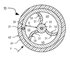
スイッチストリップ10の第1の例示的な実施形態は、内側電極20、外側電極30、空間40、3つのスペーサ50およびシース60を備える。スイッチストリップ10は、静電容量を有し、図の平面に対して垂直に長手方向に延びる。
The first exemplary embodiment of the
内側電極20は、グラファイトなどの伝導性添加物が与えられたエチレンプロピレンジエン系ゴム(EPDM)から形成される。銅などの伝導性材料の内側ワイヤ21が、内側電極20内に埋め込まれる。外側電極30は、これも内側電極20のようにグラファイトなどの伝導性添加物が与えられたEPDMから形成され、これもまた銅などの伝導性材料から作製された、埋め込まれた外側ワイヤ31を有する。内側電極20と外側電極30の間にある空間40は、空気で充填される。スペーサ50は、熱可塑性エラストマー(TPE)またはEPDMのものであり、電気的に絶縁性のものである。シース60には、塗料の摺動層61が設けられる。
The
外側電極30は、内側電極20をほぼ同心的に取り囲む。内側電極20は、外側電極30のちょうど中心にある必要はない。スイッチストリップ10の曲率に応じて、内側電極20は、一方の側が、他方の側より外側電極30に近いことが可能である。円周方向に等間隔で配置されたスペーサ50は、2つの電極20、30を互いに離間し、絶縁し、それにより、2つの電極20、30の間には依然として直接的な接触は存在しない。スイッチストリップ10が曲げられたとき、スペーサ50は、内側電極20を本質的には曲率の中立素分に沿って配置する。内側電極20および外側電極30は、そのため、径方向に互いから距離Dを離したところにある。
The
力Fが、このとき外側からスイッチストリップ10に印加された場合、最初にシース60およびそのすぐ後に外側電極30が、変形される。これは、部分的に、2つの電極20、30間の距離Dを変更する。スイッチストリップ10は本質的に円筒状のコンデンサを形成するため、スイッチストリップ10の静電容量は、距離Dが電極間20、30間で変更されたときに変化する。静電容量におけるこの変化は、以下でさらに説明する制御ユニットなどの適切な電気回路によって検出することができ、切り替えイベントをこうして構成することができる。
If a force F is applied to the
力Fが十分強い場合、スイッチストリップ10、または外側電極30およびシース60は、2つの電極20、30が互いに接触するような程度まで変形される。この短絡もまた、切り替えイベントを構成することができる。
If the force F is strong enough, the
スイッチストリップ10の第2の例示的な実施形態は、第1の例示的な実施形態に類似しており、したがって、その相違性に関してのみ説明される。
The second exemplary embodiment of the
第2の例示的な実施形態によるスイッチストリップ10は、3つのスペーサ50を有し、その各々は、2つの湾曲した側部表面51を有する。スペーサ50は、したがって、円形セグメントの形状を有する。力Fが、外側からスイッチストリップ10に印加された場合、スペーサ50は、より容易に屈するため、スイッチストリップ10のより容易な変形を可能にする。ここでは、外側電極30上に配置されたスペーサ50の第1の端部は、内側電極20上に配置されたスペーサ50の第2の端部に向かって移動される。湾曲した側部表面51は、スイッチストリップ10の円周方向にさらに湾曲され、移動される。スペーサ50は、この場合、ヒンジと同様に挙動する。
The
第3の例示的な実施形態によるスイッチストリップ10は、第1の例示的な実施形態によるスイッチストリップに類似しており、したがって、その相違性に関してのみ説明される。
The
スイッチストリップ10は、第1の例示的な実施形態と比較して、3つの突起部22を有する内側電極20を備える。突起部22は、スペーサ50と交互に円周方向に配置される。力Fが外側からスイッチストリップ10に印加された場合、外側電極30は、かなり早く内側電極20と接触する。切り替えイベントを始動させるために、より小さい力Fが、したがって必要とされる。妨害物は、こうして、かなり早くかつより安全に検出され得る。
The
第4の例示的な実施形態によるスイッチストリップ10は、他の例示的な実施形態の利点をすべて組み合わせる。スイッチストリップ10は、したがって、湾曲したスペーサ50および突起部22の両方を備える。このスイッチストリップ10は、外部力Fによってより容易に変形可能であり、容量性および触知性両方のやり方で切り替えイベントを検出することができる。
The
第5の例示的な実施形態によるスイッチストリップ10は、第3の例示的な実施形態に対応する構造を有する。加えて、この例示的な実施形態は、シース60上に配置された接着基部62を備える。接着基部62は、シース60と共押し出し成形されることが可能である。さらに、接着基部62は、スイッチストリップ10から外方を向く接着基部62の表面に施与される接着テープ63を備える。スイッチストリップ10は、したがって、キャリアプロファイルを使用せずに表面に接着式に糊付けされ得る。当然ながら、接着基部62を他の例示的な実施形態で使用することも可能である。
The
第6の例示的な実施形態によるスイッチストリップ10は、第1の例示的な実施形態に対応する構造を有する。加えて、この例示的な実施形態は、シース60上に配置された結合基部64を備える。結合基部64は、シース60と共押し出し成形されることが可能である。スイッチストリップ10は、くぼみおよびそのようなもの内にキャリアプロファイルを使用せずに結合基部64の助けで挿入され得る。当然ながら、結合基部64を他の例示的な実施形態で使用することも可能である。
The
第7の例示的な実施形態によるスイッチストリップ10は、第4の例示的な実施形態に対応する構造を有する。加えて、この例示的な実施形態は、シース60上に配置された挟み込み基部65を備える。挟み込み基部65は、シースと共押し出し成形されることが可能である。挟み込み基部65は、フランジ上に設定され得るように作製される。挟み込み基部65内に配置された挟み込みへり部66は、スイッチストリップをフランジにクリップ係合させる。当然ながら、挟み込み基部65を他の例示的な実施形態で使用することも可能である。
The
第8の例示的な実施形態によるスイッチストリップ10は、第4の例示的な実施形態に類似する。第4の例示的な実施形態とは対照的に、内側電極20の代わりに、外側電極30が3つの突起部32を備える。突起部32は、内側電極20から見たとき、凹状に湾曲した隆起として形成される。3つの、好ましくは等間隔で配置されたスペーサ50は、横断プロファイルにおいて湾曲した構成を有する。スペーサ50はまた、容易に屈することを促す脆弱化ゾーン52も有する。脆弱化ゾーン52は、たとえば、スペーサ50内のくぼみ53によって形成される。脆弱化ゾーン52は、この例示的な実施形態でのみ説明されるが、これらは、本発明の他の例示的な実施形態に適用可能である。
The
図5〜12の力矢印によって示されるように、外側からスイッチストリップ10に印加される力Fの方向は、図13の表内に示されるように、それほど重要な役割を果たさない。回転の角度が、スイッチストリップ10の円周方向に測定される。「o」として示されている回転の角度、または表示を有さない回転の角度では、スイッチストリップ10は、長手方向に見たときに上方向に曲げられた。「u」として示されている回転の角度では、スイッチストリップ10は、長手方向に下方向に曲げられた。曲げ半径は、スイッチストリップ10の曲げの中心から、摺動層61などのその外側表面まで測定される。「接触」欄は、スイッチストリップ10の電極20、30が、曲げ状態において互いに接触しているかどうかを示す。「センサ位置」欄は、スイッチストリップの配向を概略的に示す。算出された場合では、長手方向軸に沿ったスイッチストリップ10の曲げは、外側電極20の変形を引き起こし、それにより、電極20、30は、互いに接触するようになる。力Fが外側から外側電極20に印加されたときのみ、電極20、30は、互いに接触することができる。距離Dの特有の選択もまた、重要性は低く、これは、静電容量における変化または2つの電極20、30の直接的短絡のみが切り替えイベントを構成するためである。
As indicated by the force arrows in FIGS. 5-12, the direction of the force F applied to the
スイッチストリップ310の第9の例示的な実施形態は、接地電極320、センサ電極330、空間340、およびシース360を備える。スイッチストリップ310は、中心および静電容量を有し、図の平面に対して垂直に長手方向に延びる。シース360は、接地部分362およびセンサ部分363を含む。シース360は、EPDMから形成され、弾性的に変形可能であり、絶縁性のものである。接地部分362およびセンサ部分363は、本質的には、半円構成を有する。
A ninth exemplary embodiment of switch strip 310 includes a
接地電極320は、接地部分362内に配置される。接地電極320は、グラファイトなどの伝導性添加物が与えられたEPDMから形成される。銅などの伝導性材料の接地ワイヤ321が、接地電極320内に埋め込まれる。接地電極320は、中心を向く第1の内側接触表面323を有し、中心から外方を向く第1の外側接触表面324を有する。内側接触表面323は、凹状に湾曲される。接地電極322は、さらに、第1の内側接触表面323に隣接して配置された2つの突起部322を含む。突起部322は、凸状曲率を有する。突起部322の曲率半径は、内側接触表面323の曲率半径の各々より小さい。特に、2つの突起部322は、同一の曲率半径を有する。突起部322および内側接触表面323は、センサ電極330に適合され、それにより、突起部322および内側接触表面323は、接地電極320がまだ変形されていないときでもセンサ電極330を完全に包囲することができる。
The
センサ電極330は、センサ部分363内に配置される。センサ電極330は、これもまた接地電極320のように、グラファイトなどの伝導性添加物が与えられたEPDMから形成され、これもまた銅などの伝導性材料から作製された、埋め込まれたセンサワイヤ331を有する。センサ電極320は、中心を向く第2の内側接触表面333を有し、中心から外方を向く第2の外側接触表面334を有する。第2の内側接触表面333は、内側接触表面323が、変形される必要なく、その全体表面にわたって接触できるようなやり方で凸状に湾曲される。
接地電極320とセンサ電極330の間である空間340は、空気で充填される。スイッチストリップ310には、外側接触表面324、334を環境に対して絶縁する絶縁塗料の摺動層361が設けられる。スイッチストリップ310全体は、1回の加工ステップで一体的に押し出し成形されるが、これはまた、異なる方法で製造することができる。
A
力Fが、ここで外側からスイッチストリップ310に印加された場合、最初にシース360が変形され、したがってセンサ電極330が移動される。これは、2つの電極320、330間の距離Dを変更する。スイッチストリップ310はコンデンサを形成するため、スイッチストリップ310の静電容量は、電極間320、330間の距離Dが変更されたときに変化する。静電容量におけるこの変化は、以下で説明する制御ユニットなどの適切な電子回路によって検出することができ、切り替えイベントを構成することができる。
If a force F is now applied to the switch strip 310 from the outside, the
力Fが十分強い場合、スイッチストリップ310は、2つの電極320、330が、それらの内側接触表面323、333において互いに接触するような程度まで変形される。この短絡もまた、切り替えイベントを構成することができる。
If the force F is strong enough, the switch strip 310 is deformed to such an extent that the two
スイッチストリップ310の第10の例示的な実施形態は、第8の例示的な実施形態に類似しており、したがって、その相違性に関してのみ説明される。 The tenth exemplary embodiment of the switch strip 310 is similar to the eighth exemplary embodiment and is therefore described only with respect to its differences.
第9の例示的な実施形態によるスイッチストリップ310では、センサ部分363は、グラファイトなどの伝導性添加物が与えられたEPDMから形成される。
In the switch strip 310 according to the ninth exemplary embodiment, the
本発明による例示的な安全センサストリップ100は、本発明によるキャリアプロファイル110およびスイッチストリップ10を備える。キャリアプロファイル110は、取り付け部分111および受け入れ部分112を備える。取り付け部分111は、安全センサストリップ100を監視される領域に取り付けるためのものである。受け入れ部分112は、スイッチストリップ10を受け入れる。取り付け部分111には、追加的に、接着層113およびシーリング物質114が設けられて安全センサストリップ100を突起部またはフランジ上に確実に取り付ける。シーリング物質114は、突起部またはフランジを水分および汚れから保護する。加えて、シーリング物質114は、キャリアプロファイル110のシーリング作用を向上させる。
An exemplary
受け入れ部分112は、スイッチストリップ10がねじ込まれる空洞120として形成される。スイッチストリップ10のねじ込みを容易にするために、空洞120には、熱可塑性加硫物の摺動層121が設けられる。スイッチストリップ10は、ねじ込み中、ねじれる可能性があるが、これは、スイッチストリップ10の径方向の対称性により、重要ではない。安全センサストリップ100は、したがって、より容易にかつよりコスト効果高く製造可能である。
The receiving
安全センサストリップ100は、たとえば、図2および図3に概略的に示されるように摺動ドアで使用される。この場合の摺動ドアは、移動範囲221を有する閉鎖要素220である。安全センサストリップ100は、ドア縁上に配置される。図3に見るように、安全センサストリップ100は、ドアの曲率を辿る。安全センサストリップ100は、図1に示すように妨害物210を検出するための装置において使用される。そのような装置はまた、挟み込み防止保護と称される。
The
自動車車両200には、挟み込み防止保護が装備される。挟み込み防止保護は、安全センサストリップ100、閉鎖要素220および制御ユニット230を備える。閉鎖要素220は、これが開位置と閉位置の間で移動する移動範囲221を有する。閉鎖要素220は、開くまたは閉じるためにモータ222によって駆動される。モータ222は、駆動線223によって制御ユニット230に連結される。制御ユニット230は、安全センサストリップ100に連結されたセンサ線231を備える。
The
閉鎖要素220が閉じられ、移動範囲221内に妨害物210が存在する場合、安全センサストリップ100は、妨害物によって変形される。安全センサストリップ100の変形の結果、スイッチストリップ10の切り替えイベントが生じ、これは、センサ線231を介して制御ユニット230に送られる。制御ユニット231は、最初、モータ222の電源を切り、次いで、モータ222を少しの距離だけ逆行させる。このようにして、妨害物210の挟み込みが解放され、これを取り除くことができる。
If the
安全センサストリップ100の製造方法は、シース60を含むスイッチストリップ10と、受け入れ部分112および取り付け部分111を含むキャリアプロファイル110とを提供することを含む。受け入れ部分112は、空洞120を含み、取り付け部分111は平面構成を有する。
The method of manufacturing the
シース60には、摺動層61が設けられる。スイッチストリップ10の一方の端部は、キャリアプロファイル110の一方の端部上に配置され、キャリアプロファイル110の他方の端部から空洞120を通って延びる引き出し手段によって把持される。引き出し手段は、回転されながら、キャリアプロファイルの所望の長さにスイッチストリップ10が設けられるまで引き出される。ここでは、引き出し手段の回転は、スイッチストリップ10に伝達され、スイッチストリップ10は、したがって、長手方向に沿って制御された形でねじられる。取り付け部分には、接着層113が設けられる。
A sliding
スイッチストリップ10は、力Fの印加方向に関係なく、容量性または触知性のやり方で切り替えイベントを発生させることができる。スイッチストリップ10をキャリアプロファイル110内にねじ込む間、スイッチストリップ10の配向は、したがって、考慮される必要はない。摺動層61、121は、ねじ込みを容易にする。キャリアプロファイル110およびスイッチストリップ10を備える安全センサストリップ100は、より容易にかつよりコスト効果高く製造され得る。挟み込み防止保護は、自動車車両で、窓、サンルーフまたはドア用に使用され得るが、たとえばガレージドアでも使用され得る。
The
10 スイッチストリップ
20 内側電極
21 内側ワイヤ
22 突起部
30 外側電極
31 外側ワイヤ
32 突起部
40 空間
50 スペーサ
51 側部表面
52 脆弱化ゾーン
53 くぼみ
60 シース
61 摺動層
62 接着基部
63 接着テープ
64 結合基部
65 挟み込み基部
66 挟み込みへり部
100 安全センサストリップ
110 キャリアプロファイル
111 取り付け部分
112 受け入れ部分
113 接着層
114 シーリング物質
120 空洞
121 摺動層
200 自動車車両
210 妨害物を検出するための装置
220 閉鎖要素
221 移動範囲
222 モータ
223 駆動線
230 制御ユニット
231 センサ線
310 スイッチストリップ
320 接地電極
321 接地ワイヤ
322 突起部
323 凹状内側接触表面
324 第1の凸状外側接触表面
330 センサ電極
331 センサワイヤ
333 凸状内側接触表面
334 第2の凸状外側接触表面
340 空間
360 シース
361 摺動層
362 接地部分
363 センサ部分
D 距離
F 力
DESCRIPTION OF
Claims (14)
第1の電荷が印加可能である内側電極(20)と、
外側から印加された力(F)によって変形可能であり、第2の電荷が印加可能である、外側電極(30)であって、前記長手方向に対して垂直の方向に延びる断面においてほぼ円形になるように形成され、前記内側電極(20)を、距離(D)を離してほぼ同心状に取り囲む、外側電極(30)と、
空気で充填された空間(40)であって、前記外側電極(30)と前記内側電極(20)の間に配置され、誘電性のものである、空間(40)とを含み、
前記外側電極(30)が変形された際に、前記変形により、前記内側電極(20)および前記外側電極(30)を少なくとも部分的に互いに接触させることができる、スイッチストリップ(10)において、
断面において湾曲して形成され、前記スイッチストリップ(10)における同じ円周方向に湾曲された2つの湾曲した側部表面(51)を有する、少なくとも1つのスペーサ(50)であって、前記長手方向に対して垂直の方向に変形可能であり、前記内側電極(20)を前記外側電極(30)から離間し絶縁する、少なくとも1つのスペーサ(50)を有することを特徴とする、スイッチストリップ(10)。 A switch strip (10) for a device for detecting an obstruction (210) within the range (221) of movement of a closure element (220) in a motor vehicle (200) or otherwise, extending longitudinally and having a capacitance Have
An inner electrode (20) to which a first charge can be applied;
An outer electrode (30) that is deformable by a force (F) applied from the outside and to which a second charge can be applied, and is substantially circular in a cross section extending in a direction perpendicular to the longitudinal direction. An outer electrode (30) formed so as to surround the inner electrode (20) substantially concentrically at a distance (D);
A space (40) filled with air, the space (40) being disposed between the outer electrode (30) and the inner electrode (20) and being dielectric,
In the switch strip (10), when the outer electrode (30) is deformed, the deformation allows the inner electrode (20) and the outer electrode (30) to be at least partially in contact with each other,
At least one spacer (50) having two curved side surfaces (51) curved in cross-section and curved in the same circumferential direction in said switch strip (10), said longitudinal direction A switch strip (10), characterized in that it has at least one spacer (50) that is deformable in a direction perpendicular to the outer surface and that insulates the inner electrode (20) from the outer electrode (30). ).
取り付け部分(111)および受け入れ部分(112)を含むキャリアプロファイル(110)と、
前記受け入れ部分(112)内に配置された、請求項1から10のいずれか一項に記載のスイッチストリップ(10)とを備える、安全センサストリップ(100)。 A safety sensor strip (100) comprising:
A carrier profile (110) including an attachment portion (111) and a receiving portion (112);
A safety sensor strip (100) comprising a switch strip (10) according to any one of claims 1 to 10 arranged in the receiving part (112).
請求項11または12に記載の少なくとも1つの安全センサストリップ(100)と、
前記安全センサストリップ(100)に依存して前記閉鎖要素(220)の開閉作動を制御する制御ユニット(230)とを備える、装置。 A device for detecting an obstruction (210) within a range (221) of movement of a closure element (220) in a motor vehicle (200) or others,
At least one safety sensor strip (100) according to claim 11 or 12 , and
A control unit (230) for controlling the opening and closing operation of the closure element (220) depending on the safety sensor strip (100).
a) キャリアプロファイル(110)を提供するステップと、
b) 請求項1から10のいずれか一項に記載のスイッチストリップ(10)を提供するステップと、
c) 前記スイッチストリップ(10)を、回転させながら、および/または、加圧空気を前記スイッチストリップ(10)の外側表面と前記受け入れ部分(112)の内側表面との間の境界3次元領域に印加しながら、前記空洞(120)内に挿入するステップとを含む、方法。 A method of manufacturing a safety sensor strip (100) according to claim 12 , comprising:
a) providing a carrier profile (110);
b) providing a switch strip (10) according to any one of claims 1 to 10 ;
c) Rotating the switch strip (10) and / or applying pressurized air to the boundary three-dimensional region between the outer surface of the switch strip (10) and the inner surface of the receiving part (112) Inserting into the cavity (120) while applying.
Applications Claiming Priority (3)
| Application Number | Priority Date | Filing Date | Title |
|---|---|---|---|
| DE102013104967.2A DE102013104967A1 (en) | 2013-05-14 | 2013-05-14 | Safety edge, safety sensor strip and their manufacturing process as well as anti-trap protection |
| DE102013104967.2 | 2013-05-14 | ||
| PCT/EP2014/059892 WO2014184268A1 (en) | 2013-05-14 | 2014-05-14 | Switch strip, safety sensor strip and production method thereof, and also anti-trap protection |
Publications (3)
| Publication Number | Publication Date |
|---|---|
| JP2016519410A JP2016519410A (en) | 2016-06-30 |
| JP2016519410A5 JP2016519410A5 (en) | 2017-04-20 |
| JP6339179B2 true JP6339179B2 (en) | 2018-06-06 |
Family
ID=50780466
Family Applications (1)
| Application Number | Title | Priority Date | Filing Date |
|---|---|---|---|
| JP2016513356A Expired - Fee Related JP6339179B2 (en) | 2013-05-14 | 2014-05-14 | Switch strip, safety sensor strip and method for manufacturing the same, and prevention of pinching |
Country Status (8)
| Country | Link |
|---|---|
| US (1) | US9570247B2 (en) |
| EP (1) | EP2997586B1 (en) |
| JP (1) | JP6339179B2 (en) |
| KR (1) | KR101885687B1 (en) |
| CN (1) | CN105164779B (en) |
| DE (1) | DE102013104967A1 (en) |
| ES (1) | ES2601553T3 (en) |
| WO (1) | WO2014184268A1 (en) |
Families Citing this family (16)
| Publication number | Priority date | Publication date | Assignee | Title |
|---|---|---|---|---|
| JP6258735B2 (en) * | 2014-03-18 | 2018-01-10 | 西川ゴム工業株式会社 | Protector with sensor and end molding method for protector with sensor |
| DE102014109416A1 (en) * | 2014-07-04 | 2016-01-07 | Ims Gear Gmbh | Engine-gearbox connection by means of adhesive tape |
| CN105720964A (en) * | 2014-12-02 | 2016-06-29 | 天津富纳源创科技有限公司 | Pressure detection button, controller and pressure detection button operation method |
| DE102015105274B4 (en) * | 2015-04-08 | 2019-04-25 | Cooper Standard GmbH | Pinch sensor for a closure element of a motor vehicle |
| DE102016107533A1 (en) * | 2016-04-22 | 2017-10-26 | Fraunhofer-Gesellschaft zur Förderung der angewandten Forschung e.V. | Elastomer-based capacitive control and operating element |
| DE102016111322A1 (en) | 2016-06-21 | 2017-12-21 | Cooper Standard GmbH | Anti-pinch system for attachment to a vehicle part |
| DE102016218178A1 (en) | 2016-09-21 | 2018-03-22 | Brose Fahrzeugteile Gmbh & Co. Kommanditgesellschaft, Bamberg | Capacitive sensor electrode, manufacturing method for a capacitive sensor electrode and capacitive sensor |
| DE102016221895A1 (en) * | 2016-11-08 | 2018-05-09 | Brose Fahrzeugteile Gmbh & Co. Kommanditgesellschaft, Bamberg | Method for sealing a sensor electrode |
| DE102017103706A1 (en) | 2017-02-23 | 2018-08-23 | Turck Holding Gmbh | Electrode for a proximity switch |
| DE102017116392A1 (en) * | 2017-07-20 | 2019-01-24 | Huf Hülsbeck & Fürst Gmbh & Co. Kg | sensor unit |
| CN107631816A (en) * | 2017-09-05 | 2018-01-26 | 上海恩井汽车科技有限公司 | A kind of power inductive sensory appts |
| JP7037721B2 (en) * | 2017-12-08 | 2022-03-17 | 日立金属株式会社 | Manufacturing method of pressure sensor and pressure sensor |
| JP6341346B1 (en) * | 2018-02-15 | 2018-06-13 | 日立金属株式会社 | Pinch detection switch |
| DE102018110608A1 (en) * | 2018-05-03 | 2019-11-07 | Kiekert Ag | Motor vehicle drive arrangement |
| KR102483658B1 (en) * | 2020-09-10 | 2023-01-03 | (주)비토넷에이피 | Apparatus For Preventing The Parts Of The Body Pinch Using Variation Of Capacitance |
| JP2022115412A (en) * | 2021-01-28 | 2022-08-09 | 日立金属株式会社 | Pressure-sensitive sensor |
Family Cites Families (23)
| Publication number | Priority date | Publication date | Assignee | Title |
|---|---|---|---|---|
| US4293752A (en) * | 1980-01-11 | 1981-10-06 | Tapeswitch Corporation Of America | Self adhering tape switch |
| DE3921533A1 (en) * | 1989-06-30 | 1991-01-03 | Karlheinz Beckhausen | SAFETY CONTACT RAIL |
| JP2001110272A (en) * | 1999-10-12 | 2001-04-20 | Shinmei Sangyo:Kk | Omnidirectional detection type of linear switch |
| US6337549B1 (en) | 2000-05-12 | 2002-01-08 | Anthony Gerald Bledin | Capacitive anti finger trap proximity sensor |
| US7293467B2 (en) * | 2001-07-09 | 2007-11-13 | Nartron Corporation | Anti-entrapment system |
| US7139987B2 (en) | 2002-07-11 | 2006-11-21 | Cadence Design Systems, Inc. | Analog integrated circuit layout design |
| JP3831325B2 (en) | 2002-10-01 | 2006-10-11 | アスモ株式会社 | Switchgear |
| DE102005028739C5 (en) | 2005-06-21 | 2012-08-16 | Metzeler Automotive Profile Systems Gmbh | Safety edge, in particular as anti-pinch protection for a motor vehicle |
| JP2007256136A (en) * | 2006-03-24 | 2007-10-04 | Aisin Seiki Co Ltd | Touch sensor |
| DE102006015687B4 (en) * | 2006-03-27 | 2013-08-22 | Mayser Gmbh & Co. Kg | Profile for sensors |
| DE202006009189U1 (en) * | 2006-06-12 | 2007-10-18 | Brose Fahrzeugteile Gmbh & Co. Kommanditgesellschaft, Coburg | Tactile sensor |
| JP2007335266A (en) * | 2006-06-15 | 2007-12-27 | Mitsuba Corp | Pressure detection switch |
| DE102008050897A1 (en) | 2007-09-27 | 2009-07-02 | Mayser Gmbh & Co. Kg | Sensor profile for capacitive detection of e.g. article, at e.g. folding door, of motor vehicle, has two conductors spaced from each other, and multiple conductors positioned in detection direction of one of two conductors |
| JP5023994B2 (en) * | 2007-11-22 | 2012-09-12 | 日立電線株式会社 | Cord switch |
| DE102008005783B4 (en) * | 2008-01-23 | 2011-04-14 | Gerd Reime | Moisture-independent capacitive anti-trap protection |
| DE102008035634B4 (en) * | 2008-07-31 | 2018-03-22 | Mayser Gmbh & Co. Kg | Safety edge for detection of obstacles and device for detecting obstacles |
| CN201297086Y (en) * | 2008-10-31 | 2009-08-26 | 宁波信泰机械有限公司 | Clamping-proof induction strip |
| EP2256490A1 (en) | 2009-05-29 | 2010-12-01 | Bruker Chemical Analysis B.V. | Control of gas pressure for gas chromatography |
| JP5284224B2 (en) * | 2009-09-01 | 2013-09-11 | アスモ株式会社 | Switchgear |
| US8493081B2 (en) * | 2009-12-08 | 2013-07-23 | Magna Closures Inc. | Wide activation angle pinch sensor section and sensor hook-on attachment principle |
| CN201605937U (en) * | 2009-12-24 | 2010-10-13 | 宁波敏实汽车零部件技术研发有限公司 | Mounting structure of automobile sliding door anti-clamping sensing strips |
| DE102011077014A1 (en) | 2011-06-06 | 2012-12-06 | Mayser Gmbh & Co. Kg | Hollow profile for an electrical safety edge and method for detecting obstacles with an electrical safety edge |
| JP5954249B2 (en) * | 2013-04-30 | 2016-07-20 | 日立金属株式会社 | Cord switch and cord switch mounting structure |
-
2013
- 2013-05-14 DE DE102013104967.2A patent/DE102013104967A1/en not_active Withdrawn
-
2014
- 2014-05-14 US US14/890,855 patent/US9570247B2/en active Active
- 2014-05-14 KR KR1020157033974A patent/KR101885687B1/en active IP Right Grant
- 2014-05-14 JP JP2016513356A patent/JP6339179B2/en not_active Expired - Fee Related
- 2014-05-14 EP EP14725977.4A patent/EP2997586B1/en active Active
- 2014-05-14 ES ES14725977.4T patent/ES2601553T3/en active Active
- 2014-05-14 WO PCT/EP2014/059892 patent/WO2014184268A1/en active Application Filing
- 2014-05-14 CN CN201480024317.7A patent/CN105164779B/en active Active
Also Published As
| Publication number | Publication date |
|---|---|
| JP2016519410A (en) | 2016-06-30 |
| US9570247B2 (en) | 2017-02-14 |
| WO2014184268A1 (en) | 2014-11-20 |
| EP2997586B1 (en) | 2016-09-07 |
| KR101885687B1 (en) | 2018-09-11 |
| ES2601553T3 (en) | 2017-02-15 |
| CN105164779A (en) | 2015-12-16 |
| DE102013104967A1 (en) | 2014-12-04 |
| EP2997586A1 (en) | 2016-03-23 |
| US20160104585A1 (en) | 2016-04-14 |
| CN105164779B (en) | 2018-05-29 |
| KR20160007545A (en) | 2016-01-20 |
Similar Documents
| Publication | Publication Date | Title |
|---|---|---|
| JP6339179B2 (en) | Switch strip, safety sensor strip and method for manufacturing the same, and prevention of pinching | |
| US8159231B2 (en) | Method for manufacturing a sensor supporting member | |
| JP3956369B2 (en) | Capacitive sensor | |
| US6389752B1 (en) | Touch sensitive trapping protector for power operated closing devices | |
| US8397581B2 (en) | Pinch sensor with door seal | |
| US20050041375A1 (en) | Capacitive sensor having flexible polymeric conductors | |
| US20130293245A1 (en) | Sensor unit for remotely actuating a vehicle door, vehicle door having the sensor unit and method of producing the sensor unit | |
| US20090267786A1 (en) | Opening and closing apparatus | |
| JP2016519410A5 (en) | ||
| CN113985483A (en) | Body part with integrated anti-pinch system | |
| US20160305177A1 (en) | Pinching detection device | |
| JP2007256136A (en) | Touch sensor | |
| CN103109463A (en) | Capacitive distance sensor | |
| US20170284149A1 (en) | Device and vehicle for the contactless actuation of an adjustable vehicle part | |
| JP2005227243A (en) | Electrostatic capacity type sensor | |
| JP4676928B2 (en) | Switchgear | |
| JP5437597B2 (en) | Switchgear | |
| US8491033B2 (en) | Door trim for vehicle | |
| CN116075624A (en) | Clamping device for preventing human body from being clamped by utilizing electrostatic capacity change | |
| JP2008130366A (en) | Cord switch and detection device using this | |
| JP4516517B2 (en) | Open / close drive device | |
| KR102084728B1 (en) | Sensing apparatus for approach of object | |
| CN113250573B (en) | Elastically bendable hollow profile with electrical switching strip firmly integrated in the cavity of the hollow profile | |
| JP2008293816A (en) | Pressure detection switch and open/close device for vehicle | |
| CN114008429A (en) | Pinch resistant sensor with quick connect feature and method of connecting same to wire harness |
Legal Events
| Date | Code | Title | Description |
|---|---|---|---|
| A521 | Request for written amendment filed |
Free format text: JAPANESE INTERMEDIATE CODE: A523 Effective date: 20170316 |
|
| A621 | Written request for application examination |
Free format text: JAPANESE INTERMEDIATE CODE: A621 Effective date: 20170316 |
|
| A977 | Report on retrieval |
Free format text: JAPANESE INTERMEDIATE CODE: A971007 Effective date: 20180112 |
|
| A131 | Notification of reasons for refusal |
Free format text: JAPANESE INTERMEDIATE CODE: A131 Effective date: 20180123 |
|
| A521 | Request for written amendment filed |
Free format text: JAPANESE INTERMEDIATE CODE: A523 Effective date: 20180314 |
|
| TRDD | Decision of grant or rejection written | ||
| A01 | Written decision to grant a patent or to grant a registration (utility model) |
Free format text: JAPANESE INTERMEDIATE CODE: A01 Effective date: 20180424 |
|
| A61 | First payment of annual fees (during grant procedure) |
Free format text: JAPANESE INTERMEDIATE CODE: A61 Effective date: 20180509 |
|
| R150 | Certificate of patent or registration of utility model |
Ref document number: 6339179 Country of ref document: JP Free format text: JAPANESE INTERMEDIATE CODE: R150 |
|
| R250 | Receipt of annual fees |
Free format text: JAPANESE INTERMEDIATE CODE: R250 |
|
| R250 | Receipt of annual fees |
Free format text: JAPANESE INTERMEDIATE CODE: R250 |
|
| LAPS | Cancellation because of no payment of annual fees |