JP6336960B2 - Oxygen distributor - Google Patents
Oxygen distributor Download PDFInfo
- Publication number
- JP6336960B2 JP6336960B2 JP2015506306A JP2015506306A JP6336960B2 JP 6336960 B2 JP6336960 B2 JP 6336960B2 JP 2015506306 A JP2015506306 A JP 2015506306A JP 2015506306 A JP2015506306 A JP 2015506306A JP 6336960 B2 JP6336960 B2 JP 6336960B2
- Authority
- JP
- Japan
- Prior art keywords
- oxygen
- distributor
- tube
- delivery region
- wound
- Prior art date
- Legal status (The legal status is an assumption and is not a legal conclusion. Google has not performed a legal analysis and makes no representation as to the accuracy of the status listed.)
- Active
Links
- 239000001301 oxygen Substances 0.000 title claims description 297
- 229910052760 oxygen Inorganic materials 0.000 title claims description 297
- QVGXLLKOCUKJST-UHFFFAOYSA-N atomic oxygen Chemical compound [O] QVGXLLKOCUKJST-UHFFFAOYSA-N 0.000 title claims description 296
- 238000009826 distribution Methods 0.000 claims description 42
- 239000007788 liquid Substances 0.000 claims description 36
- 238000005520 cutting process Methods 0.000 claims description 28
- 239000011148 porous material Substances 0.000 claims description 6
- 238000000034 method Methods 0.000 claims description 3
- 206010052428 Wound Diseases 0.000 description 74
- 208000027418 Wounds and injury Diseases 0.000 description 74
- 239000010410 layer Substances 0.000 description 35
- 210000000416 exudates and transudate Anatomy 0.000 description 25
- 239000012530 fluid Substances 0.000 description 23
- 239000007789 gas Substances 0.000 description 20
- 230000006835 compression Effects 0.000 description 5
- 238000007906 compression Methods 0.000 description 5
- 239000000463 material Substances 0.000 description 5
- 230000002093 peripheral effect Effects 0.000 description 5
- 230000002745 absorbent Effects 0.000 description 4
- 239000002250 absorbent Substances 0.000 description 4
- 239000006260 foam Substances 0.000 description 4
- 230000035876 healing Effects 0.000 description 4
- 230000001225 therapeutic effect Effects 0.000 description 4
- 230000002209 hydrophobic effect Effects 0.000 description 3
- 229920005439 Perspex® Polymers 0.000 description 2
- 239000012790 adhesive layer Substances 0.000 description 2
- 208000015181 infectious disease Diseases 0.000 description 2
- 239000012466 permeate Substances 0.000 description 2
- 229920002635 polyurethane Polymers 0.000 description 2
- 239000004814 polyurethane Substances 0.000 description 2
- 238000007789 sealing Methods 0.000 description 2
- 239000002356 single layer Substances 0.000 description 2
- 238000003466 welding Methods 0.000 description 2
- 229920001328 Polyvinylidene chloride Polymers 0.000 description 1
- 239000000853 adhesive Substances 0.000 description 1
- 230000001070 adhesive effect Effects 0.000 description 1
- 230000009286 beneficial effect Effects 0.000 description 1
- 239000003795 chemical substances by application Substances 0.000 description 1
- 230000001684 chronic effect Effects 0.000 description 1
- 238000004891 communication Methods 0.000 description 1
- 230000008878 coupling Effects 0.000 description 1
- 238000010168 coupling process Methods 0.000 description 1
- 238000005859 coupling reaction Methods 0.000 description 1
- 230000001419 dependent effect Effects 0.000 description 1
- 238000011156 evaluation Methods 0.000 description 1
- 238000002474 experimental method Methods 0.000 description 1
- 229920002457 flexible plastic Polymers 0.000 description 1
- 238000010438 heat treatment Methods 0.000 description 1
- 230000006698 induction Effects 0.000 description 1
- 238000005304 joining Methods 0.000 description 1
- 238000002803 maceration Methods 0.000 description 1
- 238000004519 manufacturing process Methods 0.000 description 1
- 230000004060 metabolic process Effects 0.000 description 1
- 239000006199 nebulizer Substances 0.000 description 1
- 150000002926 oxygen Chemical class 0.000 description 1
- 230000000737 periodic effect Effects 0.000 description 1
- 229920003023 plastic Polymers 0.000 description 1
- 239000004033 plastic Substances 0.000 description 1
- 239000005033 polyvinylidene chloride Substances 0.000 description 1
- 230000037390 scarring Effects 0.000 description 1
- 238000012546 transfer Methods 0.000 description 1
- 239000002699 waste material Substances 0.000 description 1
- XLYOFNOQVPJJNP-UHFFFAOYSA-N water Substances O XLYOFNOQVPJJNP-UHFFFAOYSA-N 0.000 description 1
- 230000029663 wound healing Effects 0.000 description 1
- 229920001285 xanthan gum Polymers 0.000 description 1
- 229940082509 xanthan gum Drugs 0.000 description 1
- 235000010493 xanthan gum Nutrition 0.000 description 1
- 239000000230 xanthan gum Substances 0.000 description 1
Images


Classifications
-
- A61F13/05—
-
- A61F13/01042—
-
- A—HUMAN NECESSITIES
- A61—MEDICAL OR VETERINARY SCIENCE; HYGIENE
- A61G—TRANSPORT, PERSONAL CONVEYANCES, OR ACCOMMODATION SPECIALLY ADAPTED FOR PATIENTS OR DISABLED PERSONS; OPERATING TABLES OR CHAIRS; CHAIRS FOR DENTISTRY; FUNERAL DEVICES
- A61G10/00—Treatment rooms or enclosures for medical purposes
- A61G10/02—Treatment rooms or enclosures for medical purposes with artificial climate; with means to maintain a desired pressure, e.g. for germ-free rooms
- A61G10/023—Rooms for the treatment of patients at over- or under-pressure or at a variable pressure
- A61G10/026—Rooms for the treatment of patients at over- or under-pressure or at a variable pressure for hyperbaric oxygen therapy
-
- A—HUMAN NECESSITIES
- A61—MEDICAL OR VETERINARY SCIENCE; HYGIENE
- A61H—PHYSICAL THERAPY APPARATUS, e.g. DEVICES FOR LOCATING OR STIMULATING REFLEX POINTS IN THE BODY; ARTIFICIAL RESPIRATION; MASSAGE; BATHING DEVICES FOR SPECIAL THERAPEUTIC OR HYGIENIC PURPOSES OR SPECIFIC PARTS OF THE BODY
- A61H33/00—Bathing devices for special therapeutic or hygienic purposes
- A61H33/14—Devices for gas baths with ozone, hydrogen, or the like
-
- A—HUMAN NECESSITIES
- A61—MEDICAL OR VETERINARY SCIENCE; HYGIENE
- A61M—DEVICES FOR INTRODUCING MEDIA INTO, OR ONTO, THE BODY; DEVICES FOR TRANSDUCING BODY MEDIA OR FOR TAKING MEDIA FROM THE BODY; DEVICES FOR PRODUCING OR ENDING SLEEP OR STUPOR
- A61M1/00—Suction or pumping devices for medical purposes; Devices for carrying-off, for treatment of, or for carrying-over, body-liquids; Drainage systems
- A61M1/84—Drainage tubes; Aspiration tips
- A61M1/85—Drainage tubes; Aspiration tips with gas or fluid supply means, e.g. for supplying rinsing fluids or anticoagulants
-
- A—HUMAN NECESSITIES
- A61—MEDICAL OR VETERINARY SCIENCE; HYGIENE
- A61M—DEVICES FOR INTRODUCING MEDIA INTO, OR ONTO, THE BODY; DEVICES FOR TRANSDUCING BODY MEDIA OR FOR TAKING MEDIA FROM THE BODY; DEVICES FOR PRODUCING OR ENDING SLEEP OR STUPOR
- A61M13/00—Insufflators for therapeutic or disinfectant purposes, i.e. devices for blowing a gas, powder or vapour into the body
- A61M13/003—Blowing gases other than for carrying powders, e.g. for inflating, dilating or rinsing
-
- A—HUMAN NECESSITIES
- A61—MEDICAL OR VETERINARY SCIENCE; HYGIENE
- A61M—DEVICES FOR INTRODUCING MEDIA INTO, OR ONTO, THE BODY; DEVICES FOR TRANSDUCING BODY MEDIA OR FOR TAKING MEDIA FROM THE BODY; DEVICES FOR PRODUCING OR ENDING SLEEP OR STUPOR
- A61M35/00—Devices for applying media, e.g. remedies, on the human body
- A61M35/30—Gas therapy for therapeutic treatment of the skin
-
- A—HUMAN NECESSITIES
- A61—MEDICAL OR VETERINARY SCIENCE; HYGIENE
- A61F—FILTERS IMPLANTABLE INTO BLOOD VESSELS; PROSTHESES; DEVICES PROVIDING PATENCY TO, OR PREVENTING COLLAPSING OF, TUBULAR STRUCTURES OF THE BODY, e.g. STENTS; ORTHOPAEDIC, NURSING OR CONTRACEPTIVE DEVICES; FOMENTATION; TREATMENT OR PROTECTION OF EYES OR EARS; BANDAGES, DRESSINGS OR ABSORBENT PADS; FIRST-AID KITS
- A61F13/00—Bandages or dressings; Absorbent pads
- A61F2013/00089—Wound bandages
- A61F2013/00093—Wound bandages tubular
-
- A—HUMAN NECESSITIES
- A61—MEDICAL OR VETERINARY SCIENCE; HYGIENE
- A61F—FILTERS IMPLANTABLE INTO BLOOD VESSELS; PROSTHESES; DEVICES PROVIDING PATENCY TO, OR PREVENTING COLLAPSING OF, TUBULAR STRUCTURES OF THE BODY, e.g. STENTS; ORTHOPAEDIC, NURSING OR CONTRACEPTIVE DEVICES; FOMENTATION; TREATMENT OR PROTECTION OF EYES OR EARS; BANDAGES, DRESSINGS OR ABSORBENT PADS; FIRST-AID KITS
- A61F13/00—Bandages or dressings; Absorbent pads
- A61F2013/00089—Wound bandages
- A61F2013/00246—Wound bandages in a special way pervious to air or vapours
- A61F2013/00268—Wound bandages in a special way pervious to air or vapours impervious, i.e. occlusive bandage
-
- A—HUMAN NECESSITIES
- A61—MEDICAL OR VETERINARY SCIENCE; HYGIENE
- A61M—DEVICES FOR INTRODUCING MEDIA INTO, OR ONTO, THE BODY; DEVICES FOR TRANSDUCING BODY MEDIA OR FOR TAKING MEDIA FROM THE BODY; DEVICES FOR PRODUCING OR ENDING SLEEP OR STUPOR
- A61M2202/00—Special media to be introduced, removed or treated
- A61M2202/02—Gases
- A61M2202/0208—Oxygen
-
- A—HUMAN NECESSITIES
- A61—MEDICAL OR VETERINARY SCIENCE; HYGIENE
- A61M—DEVICES FOR INTRODUCING MEDIA INTO, OR ONTO, THE BODY; DEVICES FOR TRANSDUCING BODY MEDIA OR FOR TAKING MEDIA FROM THE BODY; DEVICES FOR PRODUCING OR ENDING SLEEP OR STUPOR
- A61M2205/00—General characteristics of the apparatus
- A61M2205/33—Controlling, regulating or measuring
- A61M2205/3303—Using a biosensor
Description
本発明は、傷へ酸素又はその他の治療用気体を送達するための高圧酸素分配器に関する。 The present invention relates to a high pressure oxygen distributor for delivering oxygen or other therapeutic gas to a wound.
傷への酸素の供給は治癒を促進し、瘢痕を小さくすることが知られている。組織液の酸素含有量を増大すると、損傷した組織の代謝及び修復を促進すると考えられる。 It is known that supplying oxygen to the wound promotes healing and reduces scarring. Increasing the oxygen content of the tissue fluid is thought to promote metabolism and repair of damaged tissue.
傷が慢性的になり非治癒性になった場合又は感染症が定着した場合など傷が大量の滲出液を生じる場合、治癒過程が緩慢になり、周囲の皮膚の浸軟を導く可能性がある。この種の傷は大量の滲出液を生じ、これが、傷の治療に重大な問題を引き起こす可能性がある。
ある特許文献には、酸素を拡散して傷の部位における酸素レベルを示すことができる治癒性傷用手当用品が開示されている(例えば、特許文献1参照。)。この傷用手当用品は、上側気体透過性層と下側気体透過性層の間に形成された再充填可能なリザーバを備えている。この傷用手当用品は、上側気体透過性層の周囲に重なって患者の傷の周りの皮膚に押圧されるためのリザーバの周囲を越えて延びている接着層であって、下側気体透過性層が傷を直接的に覆って位置決めされるように傷用手当用品を患者にシールする、接着層をさらに備えている。この傷用手当用品は、さらに、傷の部位における酸素レベルを示すための酸素レベルインディケータを備えている。
また、別の特許文献には、酸素等の第1流体に不透過性である層と、損傷した組織を覆って位置決めするための第1流体に透過性である層とを備えた高圧手当用品を開示していいる(例えば、特許文献2参照。)。流体透過性の層の縁部と流体不透過性の層の縁部が、共にシールされ、この手当用品の縁部は、患者の傷を包囲する皮膚に留めることができる。第1流体が送達される時、第1流体は、流体透過性の層を通して手当用品と傷の間のヘッドスペースへ透過する。傷の滲出液等の第2流体の通過が可能となるように手当用品によって形成されているミシン目が、ヘッドスペース内の圧力が所定圧力を超えて時に開口し、第2流体が流体透過性層と流体不透過性層を通過することができる。
また、別の特許文献には、損傷した組織の周りで包囲空間を形成するための傷の滲出液等の第1流体に不透過性である包囲層と、損傷した組織と接触可能でありかつ第1流体に吸収性がある吸収層と、酸素等の第2流体を包囲空間へ送達するための流体導管とを備えた、高圧手当用品が開示されている(例えば、特許文献3参照。)。この流体導管は、包囲空間内へ延びるように配置されており、損傷した組織から離間している。
また、別の特許文献には、傷を覆ってシールして位置決めするための不透過性傷カバーと、傷カバーの下かつ傷を覆って位置決めするための連続気泡フォームや強固な多孔性材料等の材料のスクリーンと、酸素及び他の薬剤を提供して傷への直接的に圧力を減じるように、傷カバー内で治療部位を覆って吸引力を供給するための真空ポンプとを備えた、傷治療装置が開示されている(例えば、特許文献4参照。)。
また、別の特許文献には、傷に隣接した環境を制御するように構成された包帯システムで表面の傷を治療するための傷治療装置開示されている(例えば、特許文献5参照。)。この装置は、傷を覆いかつ傷の周囲及び傷を覆ったキャビティの周りでシールを提供するための包帯と、キャビティ内にありかつ互いに連通している、流体供給導管及び流体排出導管と、医薬流体を傷に供給するために流体供給導管に連結されたネブライザと、傷から流体を除去するための流体排出導管に連結された廃棄物用容器とを備えている。
If the wound produces a large amount of exudate, such as if the wound becomes chronic and non-healing, or if the infection has settled, the healing process may slow down and lead to maceration of the surrounding skin . This type of wound produces a large amount of exudate, which can cause serious problems in wound healing.
One patent document discloses a healing wound dressing that can diffuse oxygen to show the oxygen level at the site of the wound (see, for example, Patent Document 1). The wound dressing includes a refillable reservoir formed between an upper gas permeable layer and a lower gas permeable layer. The wound dressing is an adhesive layer that extends over the periphery of the reservoir to be pressed against the skin around the patient's wound overlying the upper gas permeable layer, the lower gas permeable layer. It further includes an adhesive layer that seals the wound dressing to the patient such that the layer is positioned directly over the wound. The wound dressing further includes an oxygen level indicator for indicating the oxygen level at the site of the wound.
In another patent document, a high-pressure dressing comprising a layer that is impermeable to a first fluid such as oxygen and a layer that is permeable to a first fluid for positioning over damaged tissue. (For example, refer to Patent Document 2). The edge of the fluid permeable layer and the edge of the fluid impermeable layer are sealed together, and the edge of the dressing can be secured to the skin surrounding the patient's wound. When the first fluid is delivered, the first fluid permeates through the fluid permeable layer to the headspace between the dressing and the wound. The perforation formed by the dressing so that the second fluid such as wound exudate can pass through opens when the pressure in the head space exceeds a predetermined pressure, and the second fluid is fluid permeable. It can pass through the layer and the fluid impermeable layer.
Another patent document describes an envelope layer that is impermeable to a first fluid, such as wound exudate, to form an enclosed space around the damaged tissue, and is accessible to the damaged tissue and A high-pressure dressing device is disclosed that includes an absorbent layer that absorbs the first fluid and a fluid conduit for delivering a second fluid such as oxygen to the enclosed space (see, for example, Patent Document 3). . The fluid conduit is positioned to extend into the enclosed space and is spaced from the damaged tissue.
In addition, another patent document includes an impermeable wound cover for covering and sealing a wound, and an open-cell foam or a strong porous material for positioning under the wound cover and covering the wound, etc. And a vacuum pump for providing a suction force over the treatment site within the wound cover so as to provide oxygen and other agents to reduce pressure directly on the wound, A wound treatment device is disclosed (for example, see Patent Document 4).
Another patent document discloses a wound treatment apparatus for treating a surface wound with a bandage system configured to control an environment adjacent to the wound (see, for example, Patent Document 5). The apparatus includes a bandage for covering the wound and providing a seal around the wound and around the wound cavity, a fluid supply conduit and a fluid discharge conduit within the cavity and in communication with each other; A nebulizer connected to the fluid supply conduit for supplying fluid to the wound and a waste container connected to the fluid discharge conduit for removing fluid from the wound.
本発明は、参照すべき独立請求項において規定する酸素分配器又は酸素分配装置を提供する。有利な又は好ましい特徴は、従属請求項において規定する。 The invention provides an oxygen distributor or an oxygen distribution device as defined in the independent claims to be referred to. Advantageous or preferred features are defined in the dependent claims.
従って、本発明は、酸素の供給を受けるための酸素送達領域と、酸素送達領域から延びる複数の酸素分配管であって、複数の酸素分配管の中の少なくともいくつかの酸素分配管が酸素透過性液体不透過性である壁区分を備える、傷へ酸素を供給するために傷の中に位置付けできる酸素分配器を提供できる。 Accordingly, the present invention provides an oxygen delivery region for receiving supply of oxygen and a plurality of oxygen distribution pipes extending from the oxygen delivery region, wherein at least some of the oxygen distribution pipes are oxygen permeable. An oxygen distributor can be provided that can be positioned within the wound to provide oxygen to the wound, with a wall section that is impervious to liquid .
従って、酸素分配器のチューブは、傷を被覆することなく傷へ酸素供給できるようにしながら、滲出液が自由に傷から離れて流れるようにして、有利である。 Thus, the tube of the oxygen distributor is advantageous in that the exudate flows freely away from the wound while allowing oxygen to be supplied to the wound without covering the wound.
酸素分配器の寸法を変更できるように酸素分配器を切断できることが望ましい。これによって、特定の傷内部に嵌合するために切断することによって分配器の寸法を小さくできるので、病院又は開業医が貯蔵する必要のある分配器の寸法の数を減少でき有利である。 It is desirable to be able to cut the oxygen distributor so that the dimensions of the oxygen distributor can be changed. This advantageously reduces the number of dispenser dimensions that a hospital or practitioner needs to store, since the dispenser dimensions can be reduced by cutting to fit within a particular wound.
酸素がチューブ(1本又は複数本)に沿って流れるように制限することによって、酸素分配器を容易に切断できる。なぜなら、管を横切って切断しても、分配器の内部空間の小さい区分しか露出しないので、滲出液が分配器の中へ漏れる可能性及び多量の酸素が逃げる可能性を減少する。管を相互に離間することによって、酸素分配領域を相互に離間できる。これは、切断時の柔軟性を増大して、有利である。 By restricting oxygen to flow along the tube (s), the oxygen distributor can be easily cut. Because cutting across the tube exposes only a small section of the interior space of the distributor, it reduces the possibility of exudate leaking into the distributor and the escape of large amounts of oxygen. By separating the tubes from each other, the oxygen distribution regions can be separated from each other. This is advantageous because it increases the flexibility during cutting.
使用時には、標準的吸収性手当用品及び/又は圧縮包帯などの手当用品を分配器に被せて配置して、滲出液を吸い込み、その場に留めることができる。また、分配器が、傷に又は傷の周りに付着するための接着剤を持たないことが好ましい。好ましくは、分配器は、傷内部に位置付けられ、傷及び分配器が手当用品によって被覆される。 In use, a standard absorbent dressing and / or a dressing such as a compression bandage can be placed over the dispenser to draw in exudate and stay in place. It is also preferred that the dispenser does not have an adhesive to adhere to or around the wound. Preferably, the dispenser is positioned inside the wound and the wound and distributor are covered by the dressing.
好ましくは、分配器は、酸素送達領域が分配器のマニホルド又はハブを備える又は形成するように、酸素送達領域から延びる又はこれから発出する複数の管を備える。 Preferably, the dispenser comprises a plurality of tubes extending from or emanating from the oxygen delivery region such that the oxygen delivery region comprises or forms a manifold or hub of the dispenser.
酸素分配器は、ウェブ又はメッシュの形体を取ることが好ましく、管のネットワークを備えることができる。管のネットワークは、傷の様々な部分に酸素を送達できる。例えば、分配器は、酸素が酸素送達領域から分配器の全ての管へ流れるように、酸素送達領域から延びる1本の管又は複数本の管の少なくとも1本に結合される又はこれから延びる1本又はそれ以上の管を備える。 The oxygen distributor preferably takes the form of a web or mesh and can comprise a network of tubes. The network of tubes can deliver oxygen to various parts of the wound. For example, the distributor is coupled to or extending from at least one of the tube or tubes extending from the oxygen delivery region such that oxygen flows from the oxygen delivery region to all tubes of the distributor. Or, have more tubes.
酸素送達領域から延びる管は、実質的に直線的であり、かつ/又は放射状に延び、かつ/又は湾曲する。酸素送達領域は、酸素分配器の中央に位置することが好ましい。即ち、酸素の濃度又は気体圧力は、中心において最大であり、分配器又はウェブの周縁において最小である。従って、分配器の寸法を小さくするために分配器の周縁で又は酸素送達領域から離間した点で分配器を切り取り又は切断しても、過剰な酸素の損失はない。 The tube extending from the oxygen delivery region is substantially straight and / or extends radially and / or curved. The oxygen delivery region is preferably located in the center of the oxygen distributor. That is, the oxygen concentration or gas pressure is maximum at the center and minimum at the periphery of the distributor or web. Thus, cutting or cutting the distributor at the periphery of the distributor or at a point spaced from the oxygen delivery region to reduce the size of the distributor will not result in excessive oxygen loss.
好ましい実施形態において、酸素送達領域は、送達管を備えることができる。送達管は、直線的であるか、直線的でないか、又はリング又はリングの一部の形状であるか、又は円形、楕円形、長方形、正方形又は同様の形状に形成できる。酸素送達領域から延びる管(1本又は複数本)は、送達管の周りの又はその長さに沿った様々な位置から延びることができる。 In preferred embodiments, the oxygen delivery region can comprise a delivery tube. The delivery tube can be straight, not straight, or in the shape of a ring or part of a ring, or formed into a circular, elliptical, rectangular, square, or similar shape. The tube (s) extending from the oxygen delivery region can extend from various locations around or along the length of the delivery tube.
開口をリング状送達管で取り囲むことができ、送達管は、使用時に、滲出液が傷から流出できるようにする。 The opening can be surrounded by a ring-shaped delivery tube that allows exudate to flow out of the wound in use.
好ましくは、酸素送達領域は壁を備え、壁の一部または1区画は、酸素透過性でかつ液体不透過性であり、酸素が酸素送達領域から傷の隣接領域へ拡散できるようにする。 Preferably, the oxygen delivery region comprises a wall, and a portion or section of the wall is oxygen permeable and liquid impermeable so that oxygen can diffuse from the oxygen delivery region to the adjacent region of the wound.
好ましくは、酸素送達領域から延びる管(1本又は複数本)は、分配器の周縁まで延びる。分配器が例えば実質的に円形又は長方形である場合、酸素送達領域から延びる管(1本又は複数本)は、円形または長方形の外縁まで延びることができる。 Preferably, the tube (s) extending from the oxygen delivery region extends to the periphery of the distributor. If the dispenser is for example substantially circular or rectangular, the tube (s) extending from the oxygen delivery region can extend to the outer edge of the circular or rectangular shape.
分配器は、管壁を有する1本又はそれ以上の分岐管を備えることができ、管壁は、酸素透過性液体不透過性区分又は部分を有し、各分岐管は、酸素送達領域から延びる1本の管又は複数本の管の少なくとも1本から分岐するか又はこれに接続される。 The distributor can comprise one or more branch tubes having a tube wall, the tube wall having an oxygen permeable liquid impermeable section or portion, each branch tube extending from the oxygen delivery region. It is branched from or connected to at least one of the single tube or the multiple tubes.
好ましくは、分岐管は、酸素送達領域から延びるチューブから分岐する。好ましくは、分岐管は、酸素送達領域から延びるチューブの、酸素送達領域から最も離間した端部に接続される。好ましい実施形態において、1本の分岐管又は複数本の分岐管の少なくとも1本は、分配器の周縁の1区分の周りに又はこれに沿って延びる。分配器が例えば実質的に円形である場合、各分岐管は、円周縁の区分の周りに延びることができる。各分岐管は、酸素送達領域から延びる各管に対して実質的に直角に延びることができる。分岐管は連続リングを形成できる。1本の分岐管又は複数本の分岐管の少なくとも1本は、分岐管に接続される又は分岐管から延びる更なる管を持つことができる。 Preferably, the branch tube branches from a tube extending from the oxygen delivery region. Preferably, the branch tube is connected to the end of the tube extending from the oxygen delivery region that is furthest from the oxygen delivery region. In a preferred embodiment, at least one of the branch tube or the plurality of branch tubes extends around or along a section of the periphery of the distributor. If the distributor is, for example, substantially circular, each branch tube can extend around a section of the circumferential edge. Each branch tube can extend substantially perpendicular to each tube extending from the oxygen delivery region. The branch pipe can form a continuous ring. At least one of the one branch pipe or the plurality of branch pipes can have a further pipe connected to or extending from the branch pipe.
好ましくは、酸素送達領域とウェブの周縁との間の唯一の管(1本又は複数本)は、酸素送達領域から延びる管(1本又は複数本)である。任意に、分配器の周縁又は周囲に配置される各分岐管以外には、酸素送達領域から延びる管から分岐する管はない。従って、酸素送達領域から延びる各管は、2つの接合点、即ち管が酸素送達領域に接続される第1接合点及び管が分岐管の1本又はそれ以上に接続される第2接合点のみを持つことができる。 Preferably, the only tube (s) between the oxygen delivery region and the web perimeter is the tube (s) extending from the oxygen delivery region. Optionally, there is no tube branching from the tube extending from the oxygen delivery region other than each branch tube located around or around the distributor. Thus, each tube extending from the oxygen delivery region has only two junctions: a first junction where the tube is connected to the oxygen delivery region and a second junction where the tube is connected to one or more of the branch tubes. Can have.
好ましくは、分配器は、酸素送達領域から発出する管の独立した複数のサブネットワークを備える。従って、1つのサブネットワークの管は、別のサブネットワームの管と相互接続されない。各サブネットワークは、酸素送達領域から延びる管を少なくとも1本備えることができる。1つの実施例において、各サブネットワークは、酸素送達領域から延びる1本の管を備える。各サブネットワークは、酸素送達領域から延びる管(1本又は複数本)から分岐する1本又はそれ以上の分岐管を備えることができる。従って、酸素送達領域を除いて、酸素送達領域に接合される第1管及び第1管から派生する又は第1チューブから延びるチューブは、酸素送達領域に接続された第2チューブ又は第2チューブから派生する又は第2チューブから延びる他のチューブと相互接続されない。従って、酸素送達領域からのチューブの配列は、樹木の幹からの枝の配列に類似する。従って、分配器は、1つのサブサブネットワークのみが影響を受けるように切断でき、有利である。 Preferably, the distributor comprises a plurality of independent sub-networks of tubes emanating from the oxygen delivery region. Thus, one subnetwork tube is not interconnected with another subnet worm tube. Each sub-network can comprise at least one tube extending from the oxygen delivery region. In one embodiment, each subnetwork comprises a single tube extending from the oxygen delivery region. Each sub-network can comprise one or more branch tubes that branch off from the tube (s) extending from the oxygen delivery region. Thus, except for the oxygen delivery region, the first tube joined to the oxygen delivery region and the tube derived from or extending from the first tube is from the second tube or the second tube connected to the oxygen delivery region. It is not interconnected with other tubes that derive or extend from the second tube. Thus, the arrangement of tubes from the oxygen delivery region is similar to the arrangement of branches from the tree trunk. Thus, the distributor can be advantageously disconnected so that only one sub-subnetwork is affected.
好ましくは、分配器の各チューブ又はチューブの少なくともいくつかは、酸素透過性でかつ液体不透過性の管壁部分を備える。好ましくは、酸素透過性でかつ液体不透過性ではない各管壁の残り部分は、酸素不透過性でかつ液体不透過性である。好ましくは、酸素透過性でかつ液体不透過性である管壁の部分は、使用時に傷に面するための部分である。好ましくは、酸素不透過性でかつ液体不透過性である管壁部分は、使用時に傷の反対側に面する部分である。 Preferably, each tube or at least some of the tubes of the distributor comprises an oxygen permeable and liquid impermeable tube wall portion. Preferably, the remaining portion of each tube wall that is oxygen permeable and not liquid impermeable is oxygen impermeable and liquid impermeable. Preferably, the portion of the tube wall that is oxygen permeable and liquid impermeable is the portion that faces the wound when in use. Preferably, the oxygen-impermeable and liquid-impermeable tube wall portion is the portion facing the opposite side of the wound when in use.
有利なことには、分配器の全ての管壁を液体不透過性にして、傷から分配器の管の中への浸出液の一切の流れを防止できる。有利なことには、使用時に傷に面する管壁の少なくともいくつかの部分は、酸素透過性又は気体透過性として、分配器へ送達された酸素を分配器から傷へ放散又は透過できるようにすることができる。使用時に傷の反対側に面する少なくともいくつかの部分など管壁の他の部分は、分配器へ送達された酸素が、分配器から傷へ向かってのみ放散又は透過するように酸素不透過性又は気体不透過性とすることができる。しかし、本発明の別の形態において、傷の反対側に面する管壁の少なくともいくつかの部分は、酸素透過性又は気体透過性とすることもできる。分配器の管は有利なことに小さい直径なので、傷の反対側に面しかつ手当用品の下に在る管壁部分から放散する酸素は、有利な治療効果を持つのに充分傷に接近して送達できる。従って、本発明の更に別の形態において、分配器の管壁のほぼすべてを液体不透過性でかつ酸素透過性又は気体透過性とすることができる。この場合、管壁は、例えば全て同じ材料で製造でき、分配器の製造を単純化できる。 Advantageously, all tube walls of the distributor can be liquid impermeable to prevent any flow of leachate from the wound into the tube of the distributor. Advantageously, at least some portion of the tube wall facing the wound in use is oxygen permeable or gas permeable so that oxygen delivered to the distributor can be dissipated or permeated from the distributor to the wound. can do. Other parts of the tube wall, such as at least some parts facing the opposite side of the wound in use, are oxygen impermeable so that oxygen delivered to the distributor can only diffuse or permeate from the distributor towards the wound Or it can be gas-impermeable. However, in another form of the invention, at least some portions of the tube wall facing away from the wound may be oxygen permeable or gas permeable. The distributor tube is advantageously of small diameter so that oxygen released from the tube wall part facing away from the wound and under the dressing is close enough to have a beneficial therapeutic effect. Can be delivered. Thus, in yet another form of the invention, substantially all of the distributor tube wall can be liquid impermeable and oxygen permeable or gas permeable. In this case, the tube walls can all be made of the same material, for example, and the manufacture of the distributor can be simplified.
本出願において「管」(1本又は複数本)への言及は、酸素透過性でかつ液体不透過性区分を持つ壁を備える分配器の管を含むことができ、例えば、酸素送達領域から延びる各チューブ、各分岐管(存在する場合には)、及び酸素送達領域の送達管(存在する場合)を含むことができる。分岐管に接続される更なる管(1本又は複数本)を含むことができ、従って、酸素送達領域から延びる各管から派生する管を含むことができる。 References to “tube” (s) in this application can include a tube of a distributor comprising a wall having an oxygen permeable and liquid impermeable section, e.g. extending from an oxygen delivery region Each tube, each branch tube (if present), and oxygen delivery region delivery tube (if present) can be included. Additional tube (s) connected to the branch tube can be included, and thus can include tubes derived from each tube extending from the oxygen delivery region.
好ましい実施形態において、分配器の少なくとも一部は、酸素透過性液体不透過性層を酸素不透過性液体不透過性層へ接合することによって製作できる。酸素透過性液体不透過性層及び酸素不透過性液体不透過性層は、典型的には適切な可撓性プラスチック材料で作られる。各層は、典型的には0.01〜1mm、好ましくは0.05〜1mmの厚みを持つ。層は、分配器の管の1本又はそれ以上を形成するようにシール又は接合できる。 In a preferred embodiment, at least a portion of the distributor can be fabricated by joining an oxygen permeable liquid impermeable layer to an oxygen impermeable liquid impermeable layer. The oxygen permeable liquid impermeable layer and the oxygen impermeable liquid impermeable layer are typically made of a suitable flexible plastic material. Each layer typically has a thickness of 0.01 to 1 mm, preferably 0.05 to 1 mm. The layers can be sealed or joined to form one or more of the distributor tubes.
この好ましい実施形態において、酸素分配器は、1つ又はそれ以上のトラックを備えるものと見ることができ、各トラックは、酸素透過性液体不透過性層と酸素不透過性液体不透過性層が相互にシールされた区分を備えることができる。管の1本又はそれ以上は、各トラックにおいて酸素透過性液体不透過性層と酸素不透過性液体不透過性層との間に形成できる。各管は、トラックにおいてシールされた縁又はシールされた側面の間に形成できる。好ましくは、各トラックは1本の管を備えるか、又は複数の管を備えることができる。 In this preferred embodiment, the oxygen distributor can be viewed as comprising one or more tracks, each track having an oxygen permeable liquid impermeable layer and an oxygen impermeable liquid impermeable layer. Mutually sealed sections can be provided. One or more of the tubes can be formed between the oxygen permeable liquid impermeable layer and the oxygen impermeable liquid impermeable layer in each track. Each tube can be formed between a sealed edge or a sealed side in the track. Preferably, each track may comprise a single tube or may comprise a plurality of tubes.
分配器がウェブの形式を取る場合、トラックの相互接続されたネットワークがあり、管のネットワークはトラックのネットワークの中に形成できる。ネットワークの各トラックは、ウェブのストランド又はフィラメントを形成できる。好ましくは、複数のトラックがある場合、各トラックは、チューブの中でトラックに沿って運ばれる酸素が1つのトラックから別のトラックへ流動できるように、1つ又はそれ以上の他のトラックに接合される。 If the distributor takes the form of a web, there is an interconnected network of tracks and a network of tubes can be formed within the network of tracks. Each track of the network can form a strand or filament of web. Preferably, if there are multiple tracks, each track is joined to one or more other tracks so that oxygen carried along the track in the tube can flow from one track to another. Is done.
好ましい実施形態において、各トラックは、その幅を横切って1本の管のみを形成する。言い換えると、各トラックは、その内部に並列して形成された2本以上の管を持たない。これは、異なるトラック間の開放面積を最大化して、傷から分配器を通過する浸出液の流れを可能にする。 In a preferred embodiment, each track forms only one tube across its width. In other words, each track does not have two or more tubes formed in parallel within it. This maximizes the open area between the different tracks and allows the flow of leachate from the wound through the distributor.
酸素透過性液体不等性層と酸素不透過性液体不透過性層は、超音波溶接などの溶接又は誘導加熱又はその他の方法によって相互に固定できる。 The oxygen permeable liquid impermeable layer and the oxygen impermeable liquid impermeable layer can be secured together by welding such as ultrasonic welding or induction heating or other methods.
好ましくは、分配器は、中に酸素送達領域が形成されるトラックを備える。好ましくは、トラックは、内側の中央リング状トラックである。リング状トラックは、例えば、円形、楕円形又は長方形である。リング状トラックの内側縁は、滲出液が流れるための開口又は開口部を形成できる。好ましくは、放射状トラック又はスポークが中央トラックから延びる又は発出する。また、放射状トラックの外部に外側リング状トラックを備えることができる。外側リング状トラックは、分配器又はウェブの周囲を形成でき、放射状トラックによって酸素送達領域から離間できる。 Preferably, the dispenser comprises a track in which an oxygen delivery region is formed. Preferably, the track is an inner central ring track. The ring-shaped track is, for example, circular, elliptical or rectangular. The inner edge of the ring-shaped track can form an opening or opening for exudate to flow. Preferably, radial tracks or spokes extend or exit from the central track. Further, an outer ring-shaped track can be provided outside the radial track. The outer ring-shaped track can form the periphery of the distributor or web and can be spaced from the oxygen delivery region by the radial track.
酸素送達領域例えばリング状管は、中央リング状トラックの中に形成できる。放射状トラックの1つ又はそれ以上は、酸素送達領域から延びる管の1本又はそれ以上を形成できる。好ましくは、外側リング状トラックは、分岐管の1本又はそれ以上を形成する。トラックの1つ又はそれ以上の部分をその全幅を横切ってシールして、閉鎖端又は行止り端を持つ管を形成できる。トラックのシール部分は、例えば、1つのサブネットワークの管を隣のサブネットワークの管から分離できる。例えば、周縁トラックは、隣り合う分岐管の間の特定の部分又は点でシールできる。これによって、行止り端を持つ管を機械的に接合して、物理的支持体を与えながら、1つのサブネットワークのみが影響を受け残りのサブネットワークは無償のままであるように分配器を切断する機会を提供できる。例えば、分岐管を切断することなく隣り合う分岐管の間の外側トラックを横切って横断切断できる。 An oxygen delivery region, such as a ring tube, can be formed in the central ring track. One or more of the radial tracks can form one or more of the tubes extending from the oxygen delivery region. Preferably, the outer ring-shaped track forms one or more of the branch tubes. One or more portions of the track can be sealed across its entire width to form a tube with a closed or dead end. The seal portion of the track can, for example, separate one subnetwork tube from the next subnetwork tube. For example, the peripheral track can be sealed at a specific portion or point between adjacent branch pipes. This mechanically joins the tubes with dead ends and provides physical support while cutting the distributor so that only one subnetwork is affected and the remaining subnetwork remains free Can provide an opportunity to For example, a transverse cut can be made across an outer track between adjacent branch pipes without cutting the branch pipes.
分配器は、酸素送達手段を備えることができる。好ましくは、酸素送達手段は、酸素又は空気又はその他の治療用気体を酸素送達領域へ供給するように配列できる。典型的には、酸素送達手段は、導管と、電解酸素発生器、酸素シリンダ、コンプレッサ又はその類似品などの酸素源へ導管を接続するための接続手段とを備える。管の一端は、酸素送達領域に永久的に(例えばシールによって)取り付けることができる。又は、酸素送達手段は、取外し可能に酸素送達領域に接続できる。 The distributor can comprise oxygen delivery means. Preferably, the oxygen delivery means can be arranged to supply oxygen or air or other therapeutic gas to the oxygen delivery region. Typically, the oxygen delivery means comprises a conduit and connecting means for connecting the conduit to an oxygen source, such as an electrolytic oxygen generator, oxygen cylinder, compressor or the like. One end of the tube can be permanently attached (eg, by a seal) to the oxygen delivery region. Alternatively, the oxygen delivery means can be removably connected to the oxygen delivery region.
好ましくは、酸素送達手段の酸素源は、最高30ml/時好ましくは10〜20ml/時の速度で分配器へ酸素を送達するように構成される。好ましい実施形態において、酸素は、多少高圧で、例えば気圧より約50ミリバール(mbar)高い圧力で送達される。 Preferably, the oxygen source of the oxygen delivery means is configured to deliver oxygen to the dispenser at a rate of up to 30 ml / hour, preferably 10-20 ml / hour. In a preferred embodiment, oxygen is delivered at a somewhat higher pressure, for example, about 50 millibar (mbar) above atmospheric pressure.
好ましくは、各管は、連続気泡フォームなどの多孔性材料を備える又は含む。多孔性材料は、各管全体に分布できる。これによって、管を開放したままにして、例えば分配器を被って圧縮包帯を当てることによって分配器の上面に圧力が加えられても酸素を伝達できるようにする。又は、分配器の管壁の少なくとも一部は、各管のつぶれを防止するのに十分に剛性であるか又はつぶれを防止するために強化できる。 Preferably, each tube comprises or includes a porous material such as open cell foam. The porous material can be distributed throughout each tube. This allows the tube to remain open so that oxygen can be transmitted even when pressure is applied to the upper surface of the distributor, for example by applying a compression bandage over the distributor. Alternatively, at least a portion of the tube wall of the distributor is sufficiently rigid to prevent collapse of each tube or can be strengthened to prevent collapse.
複数の管が酸素伝達領域から延びる場合、酸素送達領域から延びる管又は中にこれらの管が形成されるトラックの間に、使用時に傷からの浸出液が傷から離れて流れるようにするための領域があることが好ましい。浸出液用の大きな開口又は開口部を、管の間に形成するか、又はトラックの縁の間などトラックの間に形成できる。開口は、実質的に1つ又はそれ以上のトラック及び/又は管を境界とする又はこれらによって取り囲まれることが好ましい。これによって、例えば実質的に楕円形、長方形又は台形の開口を生成できる。例えば、開口部は、内側リング状トラック、放射状トラック及び(任意に)外側リング状トランクの間に形成できる。 If multiple tubes extend from the oxygen transfer area, an area to allow exudate from the wound to flow away from the wound during use between the tubes extending from the oxygen delivery area or the track in which these tubes are formed It is preferable that there is. Large openings or openings for the leachate can be formed between the tubes or between the tracks, such as between the edges of the track. The opening is preferably substantially bounded by or surrounded by one or more tracks and / or tubes. This can produce, for example, a substantially elliptical, rectangular or trapezoidal opening. For example, the opening can be formed between an inner ring-shaped track, a radial track, and (optionally) an outer ring-shaped trunk.
但し、開口は、トラック及び/又は管によって完全に取り囲まれなくても良い。例えば、開口は、酸素送達領域から放射状に延びる2つのトラック又は2本のチューブなど2つのトラック又は2本の管の間に形成できる。 However, the opening may not be completely surrounded by the track and / or tube. For example, the opening can be formed between two tracks or two tubes, such as two tracks or two tubes extending radially from the oxygen delivery region.
有利なことに、管は、使用時に開放端を露出するように管がその幅を横切って切断される場合滲出液が実質的に管の中へ進入しないような寸法を持ち、そのように配列できる。管が十分に小さい場合、滲出液は実際には切断された管の端部をシールし、酸素が管の端部から損失されるのを防止又は減少できることが判明している。例えば、各管は、10、8、6、5、4、3、2又は1mm2以下の最大幅又は平均幅を持つことができる。好ましくは、各管は、5、4、3、2又は1mm未満の最高高さ又は平均高さを有する。好ましくは、各管は最高又は平均断面積は、25、20、15、10、5、2又は1mm2以下である。別の形態において、本発明は、本文献において説明する上記の特徴及び関連特徴を備える酸素分配器を切断するための方法を提供する。 Advantageously, the tube is dimensioned so that exudate does not substantially enter the tube when the tube is cut across its width to expose the open end in use. it can. It has been found that if the tube is sufficiently small, the exudate can actually seal the end of the cut tube and prevent or reduce the loss of oxygen from the end of the tube. For example, each tube can have a maximum or average width of 10, 8, 6, 5, 4, 3, 2 , or 1 mm 2 or less. Preferably each tube has a maximum or average height of less than 5, 4, 3, 2 or 1 mm. Preferably, each tube has a maximum or average cross-sectional area of 25, 20, 15, 10, 5, 2 , or 1 mm 2 or less. In another form, the present invention provides a method for cutting an oxygen distributor comprising the above features and related features described in this document.
好ましくは、各管の長さは、少なくともその平均又は最大幅の3、5又は7倍である。 Preferably, the length of each tube is at least 3, 5 or 7 times its average or maximum width.
好ましくは、管の内側面及び連続気泡フォームなどの管内部の材料は、湿潤又は滲出する浸出液を防止又は減少するために疎水性である。 Preferably, the internal surfaces of the tube and the material inside the tube, such as open cell foam, are hydrophobic to prevent or reduce exudate that wets or exudes.
滲出液が管へ進入するのを防止することは、感染症のリスクを回避するために重要である。 Preventing exudate from entering the tube is important to avoid the risk of infection.
好ましい実施形態において、分配器は、酸素送達領域外部の分配器の領域を形成する切断領域を備える。 In a preferred embodiment, the distributor comprises a cutting region that forms a region of the distributor outside the oxygen delivery region.
好ましくは、切断領域は、分配器の面積を減少するために切断領域の任意の場所において直線的に1回の切断が行われる場合、5本以下好ましくは4本、3本、2本又は1本以下の管が、その幅を横切って切断されるように配列される。管の幅を横切って切断することは、管の一部が取り外されるように、管の一方の側面又は縁から他方の側面又は縁まで幅全体を横切って切断することを意味する。切断は、管の長手軸に対して正確に直角を成す必要はなく、管の長手軸に対して10°又は20°又は30°を超える角度であることが好ましい。 Preferably, the cutting area is 5 or less, preferably 4, 3, 2, or 1 when a single cutting is performed linearly anywhere in the cutting area to reduce the area of the distributor. Sub-tubes are arranged to be cut across their width. Cutting across the width of the tube means cutting across the entire width from one side or edge of the tube to the other side or edge so that a portion of the tube is removed. The cut need not be exactly perpendicular to the longitudinal axis of the tube, but is preferably at an angle greater than 10 °, 20 ° or 30 ° relative to the longitudinal axis of the tube.
好ましくは、切断領域は、分配器の面積を減少するために切断領域を横切る任意の場所で直線的に1回の切断が行われる場合、切断された管のいずれの切断区分又は切断端の表面積も25、20、25、10、5、2又は1mm2以下であるように配列される。 Preferably, the cutting area is the surface area of any cutting section or cutting end of the cut tube if a single cut is made linearly anywhere across the cutting area to reduce the area of the distributor. Are also arranged to be 25, 20, 25, 10, 5, 2, or 1 mm 2 or less.
分配器の面積を減少するために切断領域の任意の場所で直線的に1回の切断が行われる場合、酸素送達領域から延びる管の3本以下好ましくは2本又は1本以下がその幅を横切って切断される。 If a single cut is made linearly anywhere in the cutting area to reduce the area of the distributor, no more than three, preferably no more than two, or no more than one tube extending from the oxygen delivery area Cut across.
好ましくは、切断領域は、分配器の面積を減少するために酸素送達領域から延びる管の1本又はそれ以上を備える切断領域の一部を横切って直線的に1回の切断が行われる場合、酸素送達領域から延びる管の1本又はそれ以上がその幅を横切って切断されるように配列される。 Preferably, the cutting region is a single cut made linearly across a portion of the cutting region comprising one or more tubes extending from the oxygen delivery region to reduce the area of the distributor. One or more of the tubes extending from the oxygen delivery region are arranged to be cut across their width.
分配器は、使用時に傷に酸素を分配するために傷の中に配置される分配器の部分から成る酸素分配部と、酸素供給源に結合するために酸素分配部から延びる酸素送達手段とを備えると考えることができる。使用時に、酸素分配部は、傷の中に位置付けでき、手当用品によって被覆でき、例えば酸素送達導管を備える酸素送達手段は、酸素供給源に結合するために手当用品の下から突出できる。 The dispenser comprises an oxygen distributor comprising a portion of the distributor disposed within the wound for use in distributing oxygen to the wound, and an oxygen delivery means extending from the oxygen distributor for coupling to an oxygen source. It can be considered to prepare. In use, the oxygen distributor can be positioned in the wound and covered by the dressing, for example an oxygen delivery means comprising an oxygen delivery conduit can protrude from under the dressing to couple to the oxygen source.
従って、酸素分配部は、酸素送達領域と、酸素送達領域から延びる管(1本又は複数本)及び分岐管(これがある場合)など酸素送達領域から延びる管から派生する管などの管とを備えるか、又はこれらによって構成できる。従って、滲出液が流れるための開口は、酸素分配部を貫通する開口である。 Thus, the oxygen distributor comprises an oxygen delivery region and a tube, such as a tube derived from a tube extending from the oxygen delivery region, such as a tube (s) extending from the oxygen delivery region and a branch tube (if any). Or can be constituted by these. Therefore, the opening for the exudate to flow is an opening that penetrates the oxygen distribution portion.
傷からの滲出液が分配器を通過して流れるための開口の総面積は、可能な限り大きくなければならない。従って、好ましい実施形態において、酸素分配部の平面における面積は、分配器の総面積の50%以下であり、分配器の面積の残り部分は開口の面積である。好ましくは、酸素分配部の面積は、分配器の総面積の40、30、20又は10%以下である。酸素分配部の面積は、使用時に酸素分配部の下方又は分配部によって被覆された傷の面積であると言える。分配器の総面積は、例えば、使用時に分配部の下方の総面積である。総面積は、分配器の周縁又は分配器の周囲によって又はその内部に形成された面積である(分配器が周縁管又はトラックを備えるか否かに関係なく)。例えば、分配器が実質的に円形である場合、面積は、円の外縁によって(少なくとも部分的に)形成される。従って、総面積は、滲出液が分配器を通過して流れるための開口(出来る限り大きいことが有利である)を含む。 The total area of the openings for the exudate from the wound to flow through the distributor should be as large as possible. Therefore, in a preferred embodiment, the area in the plane of the oxygen distributor is not more than 50% of the total area of the distributor, and the remainder of the area of the distributor is the area of the opening. Preferably, the area of the oxygen distributor is 40, 30, 20, or 10% or less of the total area of the distributor. It can be said that the area of the oxygen distribution part is an area of a flaw covered by the distribution part or below the oxygen distribution part in use. The total area of the distributor is, for example, the total area under the distributor when in use. The total area is the area formed by or around the periphery of the distributor or around the distributor (regardless of whether the distributor comprises a peripheral tube or track). For example, if the distributor is substantially circular, the area is (at least partially) formed by the outer edge of the circle. Thus, the total area includes an opening (which is advantageously as large as possible) for the exudate to flow through the distributor.
好ましい実施形態において、酸素分配部の平面における面積は、浸出液用の開口部又は開口の総面積より小さい。 In a preferred embodiment, the area in the plane of the oxygen distributor is smaller than the total area of the leachate openings or openings.
分配器は、周縁管又はトラックを備えても備えなくても良いが、いずれの場合にも、その面積は下記のように評価できる。 The distributor may or may not include a peripheral tube or track, but in either case, the area can be evaluated as follows.
酸素分配部が、酸素分配部を横切る最大長さに等しい長さ及び酸素分配部を横切る最大幅に等しい幅を有する長方形の内部に嵌合する又はこの内部に配置される場合、長方形の面積は、分配器の面積である。酸素分配部によって被覆される面積は、長方形の面積の50%以下であることが好ましい。更に好ましくは、面積は、長方形の面積の40、30、20又は10%以下である。 If the oxygen distributor fits in or is placed inside a rectangle having a length equal to the maximum length across the oxygen distributor and a width equal to the maximum width across the oxygen distributor, the area of the rectangle is , The area of the distributor. The area covered by the oxygen distributor is preferably 50% or less of the rectangular area. More preferably, the area is 40, 30, 20, or 10% or less of the rectangular area.
又は、酸素分配部が酸素分配部を横切る最大距離に等しい直径又は横行寸法を持つ円形またはその他の類似する閉鎖形状の内部に嵌合する又はこの内部に配置される場合、円形または閉鎖形状の面積は、分配器の面積である。酸素分配部によって被覆される円又はその他の形状内の面積は円又はその他の形状の面積の50%以下であることが好ましい。更に好ましくは、面積は、円又はその他の形状の面積の40、30、20又は10%以下である。 Or the area of a circular or closed shape if it fits within or is placed within a circular or other similar closed shape with a diameter or transverse dimension equal to the maximum distance across the oxygen distributed portion Is the area of the distributor. The area within the circle or other shape covered by the oxygen distributor is preferably 50% or less of the area of the circle or other shape. More preferably, the area is not more than 40, 30, 20, or 10% of the area of a circle or other shape.
酸素分配部の面積を評価するために適する閉鎖形状は、酸素分配部の半径方向最外部点を直線でつなぐ直線辺を持つ多角形である。酸素分配部が周縁管又はトラックを備える場合、その面積は、周縁管又はトラックを境界とする面積である。酸素分配システムも提供される。酸素分配システムは、上述の酸素分配器と、酸素分配器に接続されかつ酸素分配器の酸素送達領域へ酸素を供給するための酸素発生器とを備えている。 A closed shape suitable for evaluating the area of the oxygen distributor is a polygon having a straight side connecting the radially outermost points of the oxygen distributor with a straight line. When the oxygen distributor includes a peripheral pipe or track, the area is an area with the peripheral pipe or track as a boundary. An oxygen distribution system is also provided. The oxygen distribution system includes the oxygen distributor described above and an oxygen generator connected to the oxygen distributor and for supplying oxygen to the oxygen delivery region of the oxygen distributor.
酸素分配器は傷へ酸素を分配することが最も好ましいが、分配器を用いて他の治療用気体を送達することもできる。従って、分配器は、気体分配ウェブなどの気体分配器としてより普遍的用途を持つことができる。気体分配器は、気体送達領域を持つことができ、管が気体送達領域から延びる。管は、壁を持ち壁の一部は気体透過性でありかつ液体不透過性である。 Most preferably, the oxygen distributor distributes oxygen to the wound, but other therapeutic gases can be delivered using the distributor. Thus, the distributor can have a more universal application as a gas distributor such as a gas distribution web. The gas distributor can have a gas delivery region and a tube extends from the gas delivery region. The tube has a wall and part of the wall is gas permeable and liquid impermeable.
本発明の実施形態について、以下に添付図面を参照して、例として説明する。 Embodiments of the present invention will be described below by way of example with reference to the accompanying drawings.
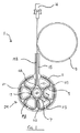
本発明の実施形態に従ったウェブ1の形式の酸素分配器を図1〜3に示す。共押出成形EVA/PVDC(NEXCEL(登録商標)MF513)から製造された上側酸素不透過性液体不透過性層3及びポリウレタン、多孔性フィルム(TREDEGAR(登録商標)BF519W)から製造された下側酸素透過性液体不透過性層5は、ウェブのストランドを形成する形状にカットされ、トラックにおいて相互にシールされる。明確に言うと、リングの形の中央内側トラック7と、内側トラックから延びる6本の放射状直線トラック又はスポーク9と、外側円周トラック1と、円周トラックから外向きに突出し6本の放射状トラックの1つと整列するタブ15の形式の1本の直線トラックと、がある。内側トラックは、中央の滲出液用孔8を形成し、さらに6つの滲出液用孔12が内側トラック、放射状トラック及び円周トラックの間に形成される。円周トラックは、ウェブの酸素分配部29の外縁を形成する。
An oxygen distributor in the form of a web 1 according to an embodiment of the invention is shown in FIGS. Upper oxygen impermeable liquid
内側トラック7内部には、リング形酸素送達管の形式の酸素送達領域又はマニホルド17が形成される。酸素送達領域からは、6つの放射状トラック9のうち5つに形成された5本の放射状管19Aが発出する。5本の放射状管の各々は分岐して、円周トラック11内部に形成される円周管又は分岐管21を形成する。5本の放射状管及びこれに接続された円周管の各々は、独立したチューブのサブネットワークを形成し、サブネットワークは、酸素送達領域を除いて、他のサブネットワークと相互連結しない。隣り合うサブネットワークの円周管は、円周トラックのシール部23によって相互に分離される。シール部は、円周管において閉鎖端を生成する。但し、円周トラックは、分配器の平面において管閉鎖端部を物理的に拘束する。
Formed inside the inner track 7 is an oxygen delivery region or manifold 17 in the form of a ring-shaped oxygen delivery tube. From the oxygen delivery region, five
長い放射状直線管19Bは、円周トラック11を横切ってかつタブ15に沿って、放射状トラック9の1つの中に形成される。この管は、分岐して円周管を形成せず、酸素送達領域17からタブ15の外側縁まで延びる。
A long radial straight tube 19B is formed in one of the
図2は、放射状管19Aの1つが内部に形成された放射状トラック9の1つの断面図を示す。管の両側において、酸素不透過性液体不透過性層3が酸素透過性液体不透過性層5にシールされる。
FIG. 2 shows a cross-sectional view of one of the
各管17、19A、21は、酸素不透過性液体不透過性層3と酸素透過性液体不透過性層5との間に形成される。ポリウレタン連続気泡フォーム6(CORPURA(登録商標)MCF03)の形の多孔性材料が、各管内部に配分される。多孔性材料は、図3において明白に示される。
Each
プラスチック導管(液体不透過性でかつ気体不透過性)の形式の酸素送達手段13は、長い放射状管19Bの1端に位置付けられ、シールされる。酸素送達手段は、酸素送達領域17に位置付けられる送達端部13Aを有する。反対端部において、酸素送達手段は、酸素供給源に接続するための接続端14を有する。
An oxygen delivery means 13 in the form of a plastic conduit (liquid and gas impermeable) is positioned and sealed at one end of a long radial tube 19B. The oxygen delivery means has a
各管の長さのほとんどにおいて、各管17、19A、21は、1.5〜2mmの幅を有する。これは、管の最小幅である。管が交差して接合部25を形成するところでは、幅は、これより大きく、約4〜5mmである。各管は、約1〜2mmの最大高さを有する。
In most of the length of each tube, each
各管の最大断面積は、約5mm2であるが、管が最小幅を有する各管の長さのほとんどにおいて、断面積は約1.5〜3mm2である。 The maximum cross-sectional area of each tube is about 5 mm 2 , but for most of the length of each tube where the tube has the smallest width, the cross-sectional area is about 1.5-3 mm 2 .
短い放射状管19Aは、約15mmの長さを有し、長い放射状管19Bは約50mmの長さを有し、タブ15の外側端と酸素送達手段の送達端部13Aとの間の距離は約46mmである。
The short
円周トラック11の外側縁の間に形成された酸素送達ウェブ1の直径は、約60mmである。 The diameter of the oxygen delivery web 1 formed between the outer edges of the circumferential track 11 is about 60 mm.
図3において陰影部で示す切断領域27は、内側トラック7と外側の円周トラック11の外側縁との間に形成される。
A cutting
円周トラックは、タブ15及び酸素送達手段13を除く、傷へ酸素を送達するためのウェブの酸素分配部29の外側縁を形成する。
The circumferential track forms the outer edge of the
使用時に、酸素送達手段13は、酸素供給源(図示せず)に接続され、ウェブ1の酸素分配部29は、傷(図示せず)の中に配置される。吸収性手当用品、ガーゼ及び/又は圧縮包帯(図示せず)などの傷用手当用品は、ウェブに被せて配置される。気圧より高い圧力の酸素が、酸素供給源から酸素送達手段13を通過して酸素送達領域17へ供給される。酸素は、酸素送達領域から短い放射状管19Aの各々を通過してウェブの周縁へ向かって流れ、各円周管21を通過する。酸素が酸素送達領域を通過し、短い放射状管を通過し、各円周管を通過するとき、酸素は、酸素透過性液体不透過性層5を通過して傷まで透過できるので、傷表面全体に酸素を分配し傷部位における酸素の濃度を増大できる。
In use, the oxygen delivery means 13 is connected to an oxygen source (not shown) and the
傷部位において生じる傷の浸出液は、滲出液用孔8、12を通過して傷部位から離れることができる。典型的には、吸収性手当用品は、ウェブ1に被せて配置され、傷を保護し、滲出液用孔を通過した浸出液を吸収する。 The wound exudate generated at the wound site can pass through the exudate holes 8 and 12 and leave the wound site. Typically, the absorbent dressing is placed over the web 1 to protect the wound and absorb the exudate that has passed through the exudate holes.
特定の状況において、例えば小さい傷を処置する際、ウェブ1を切断してその面積を減少することが望ましい。切断の必要があるとき、切断は、設定された接続領域27において行われる。
In certain situations, for example when treating small scratches, it is desirable to cut the web 1 to reduce its area. When it is necessary to disconnect, the disconnection is performed in the
切断領域における管は、ウェブの面積を減少するために切断領域27を横切って直線的に1回の切断が行われる場合、4本以下の管を横切って切断でき、2本以下の短い放射状管19Aを横切って切断される。可能な直線的な1回の切断の例として、合計4本の管を横切る切断(短い放射状管19Aを2本のみ含む)を図3において線Aによって示す。
The tubes in the cutting area can be cut across 4 or less tubes and less than 2 short radial tubes if a single cut is made linearly across the cutting
図3は、1本の管のみを切断しながらウェブの大きな面積をどのように切断できるかを示す。線Bは、1本の短い放射状管19Aのみを横切って切断するように、円周トラック11のシール領域23の2つを横切りかつ放射状トラック9の1つを横切って分配器をどのように切断できるかを示す。従って、切断によって1つのサブネットワークしか影響を受けない。
FIG. 3 shows how a large area of the web can be cut while cutting only one tube. Line B cuts the distributor across two of the sealing
酸素富化頭隙を生じてこれを維持する際の酸素分配ウェブの性能
装置
・酸素分配ウェブ(上記の図1〜3に示す通り)
・酸素送達ウェブを収容するように予穿孔されたPerspex(登録商標)スラブ
・評価ごとに較正されたAlphasense(登録商標)Ltd酸素センサ(Alphasense Ltdは、空気中で使用するために較正されかつ作業場において生命を脅かすレベルの酸素を受ける者が使用する安全に重要に係る携帯用計器に使用するように明確に設計されたセンサを提供する)
・ミリアンペア(mA)電流を表示するように設定されたデジタル電圧計(DVM)(シリアル番号1100391805)
・商標Tredegar(登録商標)として販売される疎水性、気体透過性材料のディスク(酸素分配ウェブの下側の気体透過性液体不透過性層と等しい)
・Natrox(商標)酸素供給装置(シリアル番号110212−35)−加湿酸素の連続流を供給
・ガーゼパッド−Crest Medical 8層
・単層圧縮包帯
・2mlの合成滲出液(水と5%のキサンタンガム)
Oxygen distribution web performance in creating and maintaining an oxygen-enriched headspace Equipment Oxygen distribution web (as shown in Figures 1-3 above)
Perspex® slab pre-drilled to accommodate oxygen delivery web Alphasense® Ltd oxygen sensor calibrated per evaluation (Alphasense Ltd is calibrated for use in air and the workplace Provide sensors specifically designed for use in safety-critical portable instruments used by persons receiving life-threatening levels of oxygen in
Digital voltmeter (DVM) set to display milliampere (mA) current (serial number 1100391805)
A disk of hydrophobic, gas permeable material sold under the trademark Tredegar® (equal to the gas permeable liquid impermeable layer under the oxygen distribution web)
• Natrox ™ oxygen supply (serial number 110212-35) —provides continuous flow of humidified oxygen • Gauze pad—Crest Medical 8 layers • Single layer compression bandage • 2 ml of synthetic exudate (water and 5% xanthan gum)
酸素センサは、空気中の酸素濃度を監視するように構成される。大気酸素(21%)は、〜0.097mAの信号を発する。この信号は、センサ表面の酸素濃度に比例して増大する。 The oxygen sensor is configured to monitor the oxygen concentration in the air. Atmospheric oxygen (21%) gives a signal of ~ 0.097 mA. This signal increases in proportion to the oxygen concentration on the sensor surface.
方法−酸素センサをPerspex(登録商標)固定具の表面と同平面に取り付ける。センサを滲出液から保護するために、Tredegar(登録商標)疎水性材料のディスクをセンサに被せて配置し、テープを用いてシールする。合成浸出液をTredegar(登録商標)表面に塗りつけて、その上に酸素送達ウェブを配置し、その後ガーゼを置き、最後に単層圧縮包帯を置く。センサを空気中で較正し、Natrox(商標)酸素供給源を酸素分配ウェブに接続する。時刻を記録し、周期的読取りを行う。 Method-An oxygen sensor is mounted on the same plane as the surface of the Perspex® fixture. To protect the sensor from exudate, a disk of Tredegar® hydrophobic material is placed over the sensor and sealed with tape. A synthetic leachate is applied to the Tredegar® surface and the oxygen delivery web is placed on it, after which gauze is placed, and finally a single layer compression bandage. The sensor is calibrated in air and a Natrox ™ oxygen source is connected to the oxygen distribution web. Record the time and take periodic readings.
結論−0.147mAのDVM読取り値は、「傷表面」における酸素濃度29.76%に相当し、この値は、Natrox(商標)酸素供給源に接続して3時間以内に達成される。 Conclusion-A DVM reading of -0.147 mA corresponds to an oxygen concentration of 29.76% at the "scratch surface", which is achieved within 3 hours when connected to a Natrox ™ oxygen source.
従って、上記の手当用品の組合せは、「傷表面」における酸素濃度の約50%の上昇を生じ、これは、5時間後実験を終了するまで持続された(図4)。 Thus, the above dressing combination resulted in an approximately 50% increase in oxygen concentration at the “wound surface”, which persisted after 5 hours until the end of the experiment (FIG. 4).
Claims (16)
酸素の供給を受けるための酸素送達領域(17)と、
前記酸素送達領域から延びた複数の酸素分配管(19A)であって、前記複数の酸素分配管(19A)の中の少なくともいくつかの酸素分配管(19A)が、酸素透過性液体不透過性壁区分を有する、複数の酸素分配管(19A)とを備えた、酸素分配器(1)。 In an oxygen distributor (1) that can be positioned in the wound to supply oxygen to the wound,
An oxygen delivery region (17) for receiving a supply of oxygen;
A plurality of oxygen distribution pipes (19A) extending from the oxygen delivery region, wherein at least some of the oxygen distribution pipes (19A) are oxygen-permeable liquid impervious. An oxygen distributor (1) comprising a plurality of oxygen distribution pipes (19A) having wall sections.
前記酸素分配部の平面における面積が、前記分配器の総面積の50%以下である、請求項1〜11のいずれか1項に記載の酸素分配器。 An oxygen distribution part (29) formed by the oxygen delivery region (17) and a plurality of oxygen distribution pipes (19A) extending from the oxygen delivery region;
The oxygen distributor according to any one of claims 1 to 11, wherein an area of the oxygen distributor in a plane is 50% or less of a total area of the distributor.
前記酸素分配器に接続されかつ前記酸素分配器の酸素送達領域へ酸素を供給するための酸素発生器とを備えている、酸素分配システム。 An oxygen distributor according to any one of claims 1 to 15;
And an oxygen generator for supplying oxygen to an oxygen delivery region of the oxygen distributor and connected to the oxygen distributor.
Applications Claiming Priority (5)
| Application Number | Priority Date | Filing Date | Title |
|---|---|---|---|
| GBGB1206907.6A GB201206907D0 (en) | 2012-04-19 | 2012-04-19 | Oxygen distributor |
| GB1206907.6 | 2012-04-19 | ||
| GB1207571.9A GB2513823A (en) | 2012-04-19 | 2012-05-01 | Gas distributor |
| GB1207571.9 | 2012-05-01 | ||
| PCT/GB2013/050980 WO2013156779A1 (en) | 2012-04-19 | 2013-04-18 | Oxygen distributor |
Publications (3)
| Publication Number | Publication Date |
|---|---|
| JP2015514490A JP2015514490A (en) | 2015-05-21 |
| JP2015514490A5 JP2015514490A5 (en) | 2016-05-12 |
| JP6336960B2 true JP6336960B2 (en) | 2018-06-06 |
Family
ID=46261582
Family Applications (1)
| Application Number | Title | Priority Date | Filing Date |
|---|---|---|---|
| JP2015506306A Active JP6336960B2 (en) | 2012-04-19 | 2013-04-18 | Oxygen distributor |
Country Status (7)
| Country | Link |
|---|---|
| US (2) | US10080850B2 (en) |
| EP (1) | EP2838601B1 (en) |
| JP (1) | JP6336960B2 (en) |
| CN (1) | CN104519942B (en) |
| ES (1) | ES2618223T3 (en) |
| GB (2) | GB201206907D0 (en) |
| WO (1) | WO2013156779A1 (en) |
Families Citing this family (10)
| Publication number | Priority date | Publication date | Assignee | Title |
|---|---|---|---|---|
| US10940047B2 (en) | 2011-12-16 | 2021-03-09 | Kci Licensing, Inc. | Sealing systems and methods employing a hybrid switchable drape |
| CN111991092A (en) | 2012-11-16 | 2020-11-27 | 凯希特许有限公司 | Medical drape having patterned adhesive layer and method of making same |
| EP3656362A1 (en) * | 2013-10-30 | 2020-05-27 | KCI Licensing, Inc. | Condensate absorbing and dissipating system related application |
| EP3854361B8 (en) | 2014-06-05 | 2024-03-27 | Solventum Intellectual Properties Company | Dressing with fluid acquisition and distribution characteristics |
| WO2017040045A1 (en) * | 2015-09-01 | 2017-03-09 | Kci Licensing, Inc. | Dressing with increased apposition force |
| GB2542766A (en) * | 2015-09-24 | 2017-04-05 | Inotec Amd Ltd | Wound treatment |
| WO2019007874A1 (en) * | 2017-07-07 | 2019-01-10 | Smith & Nephew Plc | Wound therapy system and dressing for delivering oxygen to a wound |
| US11836555B2 (en) | 2020-05-15 | 2023-12-05 | Brother Kogyo Kabushiki Kaisha | Information processing device outputting preceding operation command to printer before starting transmitting print execution data |
| CN112755312B (en) * | 2021-01-13 | 2022-11-22 | 广东汇鼎医疗科技有限公司 | Emergency department is with infusion oxygen therapy system |
| CN112755313B (en) * | 2021-01-13 | 2022-12-09 | 安徽一诺青春工业设计有限公司 | Emergency department's infusion oxygen therapy device |
Family Cites Families (13)
| Publication number | Priority date | Publication date | Assignee | Title |
|---|---|---|---|---|
| SE429197B (en) * | 1981-10-14 | 1983-08-22 | Frese Nielsen | SAR TREATMENT DEVICE |
| US6458109B1 (en) * | 1998-08-07 | 2002-10-01 | Hill-Rom Services, Inc. | Wound treatment apparatus |
| AU2002359830A1 (en) * | 2001-12-26 | 2003-07-24 | Hill-Rom Services, Inc. | Wound vacuum therapy dressing kit |
| US20030212357A1 (en) * | 2002-05-10 | 2003-11-13 | Pace Edgar Alan | Method and apparatus for treating wounds with oxygen and reduced pressure |
| DE10326747B4 (en) * | 2003-06-13 | 2006-11-02 | Gerlach, Jörg, Dr.med. | Perfusion unit and perfusion station for skin wound treatment and its use |
| GB0518826D0 (en) | 2005-09-15 | 2005-10-26 | Smith & Nephew | Apparatus with actives from tissue - exudialysis |
| GB0407502D0 (en) | 2004-04-02 | 2004-05-05 | Inotec Amd Ltd | Hyperbaric dressing |
| EP2144643B8 (en) | 2007-05-10 | 2020-12-30 | 3M Innovative Properties Company | Reduced pressure wound dressing having a wound contact surface with protrusions |
| US8287506B2 (en) * | 2007-10-26 | 2012-10-16 | Electrochemical Oxygen Concepts, Inc. | Apparatus and methods for controlling tissue oxygenation for wound healing and promoting tissue viability |
| CN101417161A (en) * | 2007-10-27 | 2009-04-29 | 李家付 | Multifunctional vent pipe |
| GB0815078D0 (en) | 2008-08-18 | 2008-09-24 | Inotec Amd Ltd | Hyperbaric dressing and method |
| GB2470358B (en) | 2009-05-18 | 2014-05-14 | Inotec Amd Ltd | Hyperbaric dressing and method |
| US20120059301A1 (en) * | 2010-08-30 | 2012-03-08 | Franklin Amie B | Therapuetic Diffusion Hydrocolloid Wound Dressings with Methods of Oxygen Level Indication |
-
2012
- 2012-04-19 GB GBGB1206907.6A patent/GB201206907D0/en not_active Ceased
- 2012-05-01 GB GB1207571.9A patent/GB2513823A/en active Pending
-
2013
- 2013-04-18 EP EP13718045.1A patent/EP2838601B1/en active Active
- 2013-04-18 ES ES13718045.1T patent/ES2618223T3/en active Active
- 2013-04-18 JP JP2015506306A patent/JP6336960B2/en active Active
- 2013-04-18 US US14/394,729 patent/US10080850B2/en active Active
- 2013-04-18 WO PCT/GB2013/050980 patent/WO2013156779A1/en active Application Filing
- 2013-04-18 CN CN201380029331.1A patent/CN104519942B/en active Active
-
2018
- 2018-09-21 US US16/138,840 patent/US11179274B2/en active Active
Also Published As
| Publication number | Publication date |
|---|---|
| GB201207571D0 (en) | 2012-06-13 |
| US10080850B2 (en) | 2018-09-25 |
| US11179274B2 (en) | 2021-11-23 |
| ES2618223T3 (en) | 2017-06-21 |
| GB2513823A (en) | 2014-11-12 |
| EP2838601A1 (en) | 2015-02-25 |
| JP2015514490A (en) | 2015-05-21 |
| CN104519942A (en) | 2015-04-15 |
| US20190030307A1 (en) | 2019-01-31 |
| CN104519942B (en) | 2017-10-13 |
| WO2013156779A1 (en) | 2013-10-24 |
| EP2838601B1 (en) | 2017-02-15 |
| US20150094646A1 (en) | 2015-04-02 |
| GB201206907D0 (en) | 2012-06-06 |
Similar Documents
| Publication | Publication Date | Title |
|---|---|---|
| JP6336960B2 (en) | Oxygen distributor | |
| US11565033B2 (en) | Wound debridement by irrigation with ultrasonically activated microbubbles | |
| JP2022126722A (en) | Wound care arrangement | |
| CN101478938B (en) | Dressing substrate | |
| US10973694B2 (en) | Hybrid silicone and acrylic adhesive cover for use with wound treatment | |
| US8021347B2 (en) | Thin film wound dressing | |
| US20170128642A1 (en) | Negative pressure wound therapy device | |
| US10561534B2 (en) | Dressing with fluid acquisition and distribution characteristics | |
| CN101959479B (en) | Dressing and method for applying reduced pressure to and collecting and storing fluid from a tissue site | |
| US7825289B2 (en) | Wound dressing adhesive compression device | |
| CN106659590A (en) | Wound dressing | |
| KR20100103860A (en) | Low-profile reduced pressure treatment system | |
| US20210236342A1 (en) | Wound Dressings and Systems with Low-Flow Therapeutic Gas Sources for Topical Wound Therapy and Related Methods | |
| JP2015514490A5 (en) | ||
| CN102159166A (en) | Hyperbaric dressing and method | |
| US20230088196A1 (en) | Wound sealing film | |
| CN202397951U (en) | Drainage device | |
| GB2542766A (en) | Wound treatment |
Legal Events
| Date | Code | Title | Description |
|---|---|---|---|
| A521 | Request for written amendment filed |
Free format text: JAPANESE INTERMEDIATE CODE: A523 Effective date: 20160311 |
|
| A621 | Written request for application examination |
Free format text: JAPANESE INTERMEDIATE CODE: A621 Effective date: 20160311 |
|
| A977 | Report on retrieval |
Free format text: JAPANESE INTERMEDIATE CODE: A971007 Effective date: 20170127 |
|
| A131 | Notification of reasons for refusal |
Free format text: JAPANESE INTERMEDIATE CODE: A131 Effective date: 20170207 |
|
| A521 | Request for written amendment filed |
Free format text: JAPANESE INTERMEDIATE CODE: A523 Effective date: 20170427 |
|
| A131 | Notification of reasons for refusal |
Free format text: JAPANESE INTERMEDIATE CODE: A131 Effective date: 20170926 |
|
| A521 | Request for written amendment filed |
Free format text: JAPANESE INTERMEDIATE CODE: A523 Effective date: 20171018 |
|
| TRDD | Decision of grant or rejection written | ||
| A01 | Written decision to grant a patent or to grant a registration (utility model) |
Free format text: JAPANESE INTERMEDIATE CODE: A01 Effective date: 20180403 |
|
| A61 | First payment of annual fees (during grant procedure) |
Free format text: JAPANESE INTERMEDIATE CODE: A61 Effective date: 20180507 |
|
| R150 | Certificate of patent or registration of utility model |
Ref document number: 6336960 Country of ref document: JP Free format text: JAPANESE INTERMEDIATE CODE: R150 |
|
| R250 | Receipt of annual fees |
Free format text: JAPANESE INTERMEDIATE CODE: R250 |
|
| R250 | Receipt of annual fees |
Free format text: JAPANESE INTERMEDIATE CODE: R250 |
|
| R250 | Receipt of annual fees |
Free format text: JAPANESE INTERMEDIATE CODE: R250 |