JP6336593B2 - Communication apparatus and communication method - Google Patents
Communication apparatus and communication method Download PDFInfo
- Publication number
- JP6336593B2 JP6336593B2 JP2016533843A JP2016533843A JP6336593B2 JP 6336593 B2 JP6336593 B2 JP 6336593B2 JP 2016533843 A JP2016533843 A JP 2016533843A JP 2016533843 A JP2016533843 A JP 2016533843A JP 6336593 B2 JP6336593 B2 JP 6336593B2
- Authority
- JP
- Japan
- Prior art keywords
- terminal device
- base station
- frequency bands
- restricted frequency
- restricted
- Prior art date
- Legal status (The legal status is an assumption and is not a legal conclusion. Google has not performed a legal analysis and makes no representation as to the accuracy of the status listed.)
- Active
Links
Images


Classifications
-
- H—ELECTRICITY
- H04—ELECTRIC COMMUNICATION TECHNIQUE
- H04W—WIRELESS COMMUNICATION NETWORKS
- H04W72/00—Local resource management
- H04W72/04—Wireless resource allocation
- H04W72/044—Wireless resource allocation based on the type of the allocated resource
- H04W72/0453—Resources in frequency domain, e.g. a carrier in FDMA
-
- H—ELECTRICITY
- H04—ELECTRIC COMMUNICATION TECHNIQUE
- H04W—WIRELESS COMMUNICATION NETWORKS
- H04W72/00—Local resource management
- H04W72/20—Control channels or signalling for resource management
- H04W72/23—Control channels or signalling for resource management in the downlink direction of a wireless link, i.e. towards a terminal
-
- H—ELECTRICITY
- H04—ELECTRIC COMMUNICATION TECHNIQUE
- H04W—WIRELESS COMMUNICATION NETWORKS
- H04W8/00—Network data management
- H04W8/18—Processing of user or subscriber data, e.g. subscribed services, user preferences or user profiles; Transfer of user or subscriber data
- H04W8/20—Transfer of user or subscriber data
-
- H—ELECTRICITY
- H04—ELECTRIC COMMUNICATION TECHNIQUE
- H04W—WIRELESS COMMUNICATION NETWORKS
- H04W4/00—Services specially adapted for wireless communication networks; Facilities therefor
- H04W4/70—Services for machine-to-machine communication [M2M] or machine type communication [MTC]
-
- H—ELECTRICITY
- H04—ELECTRIC COMMUNICATION TECHNIQUE
- H04W—WIRELESS COMMUNICATION NETWORKS
- H04W72/00—Local resource management
- H04W72/20—Control channels or signalling for resource management
- H04W72/21—Control channels or signalling for resource management in the uplink direction of a wireless link, i.e. towards the network
-
- H—ELECTRICITY
- H04—ELECTRIC COMMUNICATION TECHNIQUE
- H04W—WIRELESS COMMUNICATION NETWORKS
- H04W74/00—Wireless channel access, e.g. scheduled or random access
- H04W74/04—Scheduled or contention-free access
- H04W74/06—Scheduled or contention-free access using polling
Description
本開示は、通信装置及び通信方法に関する。 The present disclosure relates to a communication device and a communication method.
本明細書に提供される「背景技術」の説明は、本開示の文脈を概括的に提示することを目的としている。現時点において名前が挙げられている発明者らの研究は、この背景技術のセクションで説明されている範囲内において、説明されていなければ出願時において先行技術として認められ得ない説明の局面と同様に、本発明に対する先行技術として明示的にも黙示的にも認められない。 The description of “background art” provided herein is for the purpose of generally presenting the context of the disclosure. The studies of the inventors who are named at the present time are within the scope described in this background art section, as well as aspects of explanation that would otherwise not be recognized as prior art at the time of filing. It is not explicitly or implicitly accepted as prior art to the present invention.
本発明は、無線通信システム及び無線通信方法に関し、具体的には、無線通信システムにおける制限された帯域幅/仮想キャリア動作のためのシステム及び方法に関する。 The present invention relates to a wireless communication system and a wireless communication method, and more particularly, to a system and method for limited bandwidth / virtual carrier operation in a wireless communication system.
モバイル通信システムは、ここ10年ほどの間にGSMシステム(Global System for Mobile communications)から3Gシステムへと進化し、今では、パケットデータ通信及び回路交換通信を含んでいる。3GPP(third generation partnership project)は、LTE(Long Term Evolution)と呼ばれる第4世代のモバイル通信システムを開発している。LTEでは、コアネットワーク部分を進化させて、以前のモバイル無線ネットワークアーキテクチャのコンポーネントと、ダウンリンク上では直交周波数分割多重(Orthogonal Frequency Division Multiplexing(OFDM))に基づきアップリンク上ではシングルキャリア周波数分割多重アクセス(Single Carrier Frequency Division Multiple Access(SC−FDMA))に基づく無線アクセスインターフェイスと、の併合に基づいた、より簡略化されたアーキテクチャを形成している。 Mobile communication systems have evolved from GSM systems (Global System for Mobile communications) to 3G systems in the last decade or so, and now include packet data communications and circuit switched communications. The third generation partnership project (3GPP) is developing a fourth generation mobile communication system called LTE (Long Term Evolution). LTE evolves the core network part to include components of previous mobile radio network architectures and Orthogonal Frequency Division Multiplexing (OFDM) on the downlink and single carrier frequency division multiple access on the uplink. A more simplified architecture based on merging with a radio access interface based on (Single Carrier Frequency Division Multiple Access (SC-FDMA)) is formed.
3GPP定義のUMTS及びLTE(Long Term Evolution)アーキテクチャに基づくモバイル通信システムなどの第3世代及び第4世代のモバイル通信システムは、前世代のモバイル通信システムによって提供される単純な音声及びメッセージングサービスよりもより高性能なサービスをサポートすることができる。 Third and fourth generation mobile communication systems, such as mobile communication systems based on 3GPP defined UMTS and Long Term Evolution (LTE) architectures, are more than simple voice and messaging services provided by previous generation mobile communication systems. It can support higher performance services.
例えば、LTEシステムによって提供される改善された無線インターフェイス及び拡張されたデータレートにより、以前は固定回線データ接続を介してのみ利用することのできたモバイルビデオストリーミング及びモバイルビデオ会議といった高データレートのアプリケーションをユーザは享受することができる。このため、第3世代及び第4世代のネットワークを配備することが強く望まれており、それらのネットワークのカバレッジエリア、すなわちそれらのネットワークへのアクセスが可能な地理的な場所は、急速に増大することが予想される。 For example, high data rate applications such as mobile video streaming and mobile video conferencing that were previously only available over fixed line data connections due to the improved radio interface and extended data rate provided by the LTE system. Users can enjoy it. For this reason, it is highly desirable to deploy third and fourth generation networks, and the coverage areas of those networks, i.e. the geographical locations where they can be accessed, increase rapidly. It is expected that.
第3世代及び第4世代のネットワークの広範囲にわたる配備を見込んで、利用可能な高データレートを活用するのではなく代わりに堅牢な無線インターフェイスとカバレッジエリアの増大するユビキタス性とを活用する類のデバイス及びアプリケーションが、並行して配備されてきている。例として、いわゆるマシンタイプ通信(MTC)アプリケーションがあるが、当該アプリケーションのいくつかは、いくつかの点で、少量のデータを比較的低い頻度で通信する半自律又は自律無線通信デバイス(MTCデバイス)によって代表される。例として、いわゆるスマートメーターがあるが、当該メーターは、例えば、顧客の家に配置され、顧客が消費したガス、水道、電気などのユーティリティに関して中央のMTCサーバへ周期的にデータを送り返す。スマートメータリングは、潜在的なMTCデバイスアプリケーションの1つの例にすぎない。MTCタイプのデバイスの特徴に関するさらなる情報については、例えば、ETSI TS 122 368 V10.530(2011−07)/3GPP TS 22.368 version 10.5.0 Release 10)[1]などの、対応する標準を参照されたい。 In anticipation of widespread deployment of 3rd and 4th generation networks, instead of taking advantage of the high data rates available, instead taking advantage of robust wireless interfaces and increased ubiquitous coverage areas And applications have been deployed in parallel. Examples are so-called machine type communication (MTC) applications, some of which are semi-autonomous or autonomous wireless communication devices (MTC devices) that communicate a small amount of data relatively infrequently in some respects. Represented by An example is a so-called smart meter, which is located at the customer's home, for example, and periodically sends data back to the central MTC server for utilities such as gas, water and electricity consumed by the customer. Smart metering is just one example of a potential MTC device application. For further information on the characteristics of MTC type devices, see corresponding standards such as, for example, ETSI TS 122 368 V10.530 (2011-07) / 3GPP TS 22.368 version 10.5.0 Release 10) [1]. Please refer to.
第3世代又は第4世代のモバイル通信ネットワークによって提供される広いカバレッジエリアを利用することはMTCタイプの端末などの端末にとって便利ではあろうが、現在のところ不都合な点がある。スマートフォンなどの従来の第3世代又は第4世代の移動端末とは異なり、MTCタイプの端末にとっての主要な原動力(driver)は、そうした端末が比較的単純でかつ安価であって欲しいという要望であろう。MTCタイプの端末によって典型的に実行される種類の機能(例えば、簡単な収集及びレポート/比較的少量のデータの受信)には、例えば、ビデオストリーミングをサポートするスマートフォンと比較して、実行するのに特に複雑な処理を必要としない。しかしながら、第3世代及び第4世代のモバイル通信ネットワークは、典型的に、高度なデータ変調技術を用い、無線インターフェイス上での広い帯域幅の使用をサポートする。この実現のためにはより複雑で高価な無線トランシーバ及びデコーダが必要となる可能性がある。スマートフォンは典型的なスマートフォンタイプの機能を実行するために強力なプロセッサを典型的に必要とするため、スマートフォン内にそうした複雑なエレメントを含むことは通常妥当である。しかしながら、上述のように、比較的安価でより単純な、それでいてLTEタイプのネットワークを使用して通信することができるデバイスを使用したいという要望が現在ある。 Utilizing the wide coverage area provided by third or fourth generation mobile communication networks may be convenient for terminals such as MTC type terminals, but currently has disadvantages. Unlike traditional 3rd or 4th generation mobile terminals such as smartphones, the main driver for MTC type terminals is the desire for such terminals to be relatively simple and inexpensive. Let's go. The types of functions typically performed by MTC-type terminals (eg, simple collection and reporting / reception of relatively small amounts of data) are performed, for example, compared to smartphones that support video streaming. It does not require particularly complicated processing. However, third generation and fourth generation mobile communication networks typically use advanced data modulation techniques to support the use of wide bandwidth over the air interface. This implementation may require more complex and expensive wireless transceivers and decoders. Because smartphones typically require powerful processors to perform typical smartphone-type functions, it is usually reasonable to include such complex elements within the smartphone. However, as noted above, there is currently a desire to use a device that is relatively inexpensive and simpler yet can communicate using an LTE type network.
このことを考慮して、例えば、GB 2 487 906[2]、GB 2 487 908[3]、GB 2 487 780[4]、GB 2 488 513[5]、GB 2 487 757[6]、GB 2 487 909[7]、GB 2 487 907[8]及びGB 2 487 782[9]に記載されているように、「ホストキャリア」の帯域幅内で動作するいわゆる「仮想キャリア」の概念が提案されている。仮想キャリアの概念の根底にある1つの原理は、より広い帯域幅のホストキャリア内の周波数小領域(subregion)が、所定の端末デバイスとの少なくとも一部の種類の通信のために、自立型の(self-contained)キャリアとして使用されるように構成される、ということである。
Considering this, for example,
参照文献[2]から[9]に記載されているようないくつかの実装においては、仮想キャリアを使用する端末デバイスのためのダウンリンク制御シグナリング及びユーザプレーンデータはすべて、周波数小領域内で伝達される。仮想キャリア上で動作する端末デバイスは、制限された周波数帯域を知らされるので、基地局からデータを受信するために送信リソースの対応するサブセットを受信及び復号するだけでよい。このアプローチの利点は、比較的狭い帯域幅にわたってのみ動作することができる、ケイパビリティの低い端末デバイスによって使用されるためのキャリアを提供することである。これにより、デバイスは、全帯域幅の動作をサポートする必要なしに、LTEタイプのネットワーク上で通信することができる。復号されねばならない信号の帯域幅を減じることにより、仮想キャリア上で動作するように構成されるデバイスのフロントエンド処理の要件(例えば、FFT、チャネル推定、サブフレームバッファリング等)が減じられる。というのも、それらの機能の複雑性は、概して、受信される信号の帯域幅に関連しているためである。 In some implementations, such as those described in references [2] to [9], all downlink control signaling and user plane data for terminal devices using virtual carriers are carried in the sub-frequency domain. Is done. Since the terminal device operating on the virtual carrier is informed of the limited frequency band, it only needs to receive and decode a corresponding subset of transmission resources in order to receive data from the base station. The advantage of this approach is that it provides a carrier for use by low-capacity terminal devices that can only operate over a relatively narrow bandwidth. This allows devices to communicate over LTE type networks without having to support full bandwidth operation. By reducing the bandwidth of the signal that must be decoded, the front-end processing requirements (eg, FFT, channel estimation, subframe buffering, etc.) of a device configured to operate on a virtual carrier are reduced. This is because the complexity of their functions is generally related to the bandwidth of the received signal.
LTEタイプのネットワーク上で通信するように構成されるデバイスに求められる複雑性を低減するための他の仮想キャリアアプローチが、GB 2 497 743[10]及びGB 2 497 742[11]に提案されている。これらの文献は、基地局と低減ケイパビリティ端末デバイスとの間でデータを通信するための方式であって、低減ケイパビリティ端末デバイスのための物理レイヤ制御情報を、(従来のLTE端末デバイスのためのような)ホストキャリアの全周波数帯域の中から選択されるサブキャリアを使用して基地局から送信する、方式を提案している。しかしながら、低減ケイパビリティ端末デバイスのための上位レイヤデータ(例えば、ユーザプレーンデータ)は、システム周波数帯域内でシステム周波数帯域よりも小さい制限された周波数帯域内から選択されるサブキャリアのみを使用して送信される。このため、このアプローチでは、1つの特定の端末デバイスのためのユーザプレーンデータは、周波数リソースの1つのサブセット(すなわち、ホストキャリアの送信リソース内でサポートされる1つの仮想キャリア)に制限され得るのに対し、制御シグナリングは、ホストキャリアの全帯域幅を使用して通信される。端末デバイスは、制限された周波数帯域を知らされ、それ故に、上位レイヤデータが送信されている期間中は、その制限された周波数帯域内のデータをバッファ及び処理するだけでよい。物理レイヤ制御情報が送信されている期間中は、端末デバイスは、システムの全周波数帯域をバッファ及び処理する。このため、低減ケイパビリティ端末デバイスは、広い周波数レンジ上で物理レイヤ制御情報が送信されるネットワーク内に組み込まれてよく、ただし、上位レイヤデータについてはより小さな周波数レンジを処理するのに十分なメモリと処理能力とを有するのみでよい。このアプローチは、ときに、「T型」割り当てと呼ばれることがある。なぜなら、低減ケイパビリティ端末デバイスによって使用されるべきダウンリンク時間・周波数リソースグリッドのエリアが、典型的に、ほぼT形状をなすからである。
Other virtual carrier approaches to reduce the complexity required for devices configured to communicate over LTE type networks were proposed in
このように、仮想キャリアの概念は、例えばトランシーバの帯域幅及び/又は処理力の観点で低減されたケイパビリティを有する端末デバイスが、LTEタイプのネットワーク内でサポートされることを可能にする。上述のように、これは、比較的安価でかつ複雑性の低いデバイスがLTEタイプのネットワークを使用して通信することを可能にするのに有益であり得る。 In this way, the concept of virtual carrier allows terminal devices with reduced capabilities in terms of transceiver bandwidth and / or processing power, for example, to be supported in LTE type networks. As mentioned above, this can be beneficial to allow relatively inexpensive and low complexity devices to communicate using LTE type networks.
いくつかの状況では、1つのホストキャリア内で2つ以上の仮想キャリアがサポートされ得る。この場合、ホストキャリアの帯域幅内で異なる周波数に異なる仮想キャリアが位置し、個々の端末デバイスは、複数の仮想キャリアのうちの1つに割り当てられる。このアプローチを使用すれば、仮想キャリア通信を使用してサポートされることができる端末デバイスの数を増やすことができる。しかしながら、これを行うためには、所与の端末デバイスによってどの特定の周波数リソース(すなわち、複数の仮想キャリアのうちのどれ)が使用されるべきかを、個々の端末デバイスと基地局とが設定する必要がある。典型的に、これは、例えばどの仮想キャリアに端末デバイスが割り当てられるかを基地局が端末デバイスへ通知する等、基地局とそれぞれの端末デバイスとの間である程度の制御シグナリングが交換されることを必要とする。このように基地局と端末デバイスとの間で端末デバイス固有の制御シグナリングを交換せねばならないことで、いくつかの不利益が生じる。例えば、接続の確立中に専用のシグナリングにおいて情報が交換されるため、シグナリングの複雑性が増す可能性があり、より一般的には、特に1つのセル内に数多くのデバイスが存在する場合に、通信システムにおける制御シグナリングのオーバヘッドが増加する。 In some situations, more than one virtual carrier may be supported within a single host carrier. In this case, different virtual carriers are located at different frequencies within the bandwidth of the host carrier, and each terminal device is assigned to one of a plurality of virtual carriers. Using this approach, the number of terminal devices that can be supported using virtual carrier communication can be increased. However, in order to do this, the individual terminal devices and the base station set which specific frequency resources (ie which of the multiple virtual carriers) should be used by a given terminal device. There is a need to. Typically, this means that some control signaling is exchanged between the base station and each terminal device, e.g. the base station informs the terminal device to which virtual carrier the terminal device is assigned. I need. In this way, terminal device specific control signaling must be exchanged between the base station and the terminal device, resulting in several disadvantages. For example, information is exchanged in dedicated signaling during connection establishment, which can increase signaling complexity, and more generally, especially when there are a large number of devices in a cell. The overhead of control signaling in the communication system increases.
したがって、無線通信システムにおいて特定の端末デバイスを特定の仮想キャリアへ割り振るためのアプローチが望まれる。 Therefore, an approach for allocating specific terminal devices to specific virtual carriers in a wireless communication system is desired.
本開示の第1の局面に従えば、システム周波数帯域幅(ホストキャリア)にわたり、またシステム周波数帯域幅内でかつシステム周波数帯域幅よりも狭い複数の制限された周波数帯域(仮想キャリア)内での少なくともいくつかの端末デバイスとの少なくとも一部の通信をサポートする無線インターフェイスを使用するダウンリンク通信が基地局によってなされる無線通信システムにおける端末デバイスの動作方法であって、当該方法は、端末デバイスのための識別子に基づいて複数の制限された周波数帯域の中から1つの制限された周波数帯域を選択することと、選択され制限された周波数帯域内で基地局からダウンリンク通信を受信するように端末デバイスを構成することと、を含む方法、が提供される。 According to a first aspect of the present disclosure, over a system frequency bandwidth (host carrier) and within a plurality of restricted frequency bands (virtual carriers) within the system frequency bandwidth and narrower than the system frequency bandwidth. A method of operating a terminal device in a wireless communication system in which downlink communication using a radio interface that supports at least some communication with at least some terminal devices is performed by a base station, the method comprising: Selecting a restricted frequency band from a plurality of restricted frequency bands based on an identifier for receiving the downlink communication from the base station within the selected restricted frequency band Configuring the device.
本開示の第2の局面に従えば、システム周波数帯域幅にわたり、またシステム周波数帯域幅内でかつシステム周波数帯域幅よりも狭い複数の制限された周波数帯域内での少なくともいくつかの端末デバイスとの少なくとも一部の通信をサポートする無線インターフェイスを使用するダウンリンク通信が基地局によってなされる無線通信システムにおいて使用される端末デバイスであって、当該端末デバイスはプロセッサユニットとトランシーバユニットとを含み、当該プロセッサユニットは、端末デバイスのための識別子に基づいて複数の制限された周波数帯域の中から1つの制限された周波数帯域を選択するように、及び、選択され制限された周波数帯域内で基地局からダウンリンク通信を受信するようにトランシーバユニットを構成するように構成される、端末デバイス、が提供される。 According to a second aspect of the present disclosure, with at least some terminal devices over a system frequency bandwidth and within a plurality of restricted frequency bands within the system frequency bandwidth and narrower than the system frequency bandwidth A terminal device used in a wireless communication system in which downlink communication using a radio interface that supports at least some communication is performed by a base station, the terminal device including a processor unit and a transceiver unit, the processor The unit selects a restricted frequency band from among the restricted frequency bands based on an identifier for the terminal device, and downloads from the base station within the selected restricted frequency band. Configuring the transceiver unit to receive link communications Uni configured, the terminal device is provided.
本開示の第3の局面に従えば、システム周波数帯域幅にわたり、またシステム周波数帯域幅内でかつシステム周波数帯域幅よりも狭い複数の制限された周波数帯域内での少なくともいくつかの端末デバイスとの少なくとも一部の通信をサポートする無線インターフェイスを使用するダウンリンク通信が基地局によってなされる無線通信システムにおける基地局の動作方法であって、当該方法は、端末デバイスのための識別子に基づいて複数の制限された周波数帯域の中から端末デバイスのためのダウンリンク通信のために使用されるべき1つの制限された周波数帯域を選択することと、選択され制限された周波数帯域内で端末デバイスへダウンリンク通信を送信することと、を含む方法、が提供される。 According to a third aspect of the present disclosure, with at least some terminal devices over a system frequency bandwidth and within a plurality of restricted frequency bands within the system frequency bandwidth and narrower than the system frequency bandwidth. A method for operating a base station in a wireless communication system in which downlink communication using a wireless interface that supports at least some communication is performed by the base station, the method comprising: Selecting one restricted frequency band to be used for downlink communication for the terminal device from among the restricted frequency bands and downlinking to the terminal device within the selected restricted frequency band Transmitting the communication.
本開示の第4の局面に従えば、システム周波数帯域幅にわたり、またシステム周波数帯域幅内でかつシステム周波数帯域幅よりも狭い複数の制限された周波数帯域内での少なくともいくつかの端末デバイスとの少なくとも一部の通信をサポートする無線インターフェイスを使用するダウンリンク通信が基地局によってなされる無線通信システムにおいて使用される基地局であって、当該基地局はプロセッサユニットとトランシーバユニットとを含み、当該プロセッサユニットは、端末デバイスのための識別子に基づいて複数の制限された周波数帯域の中から端末デバイスとのダウンリンク通信のために使用されるべき1つの制限された周波数帯域を選択するように、及び、選択され制限された周波数帯域内で端末デバイスへダウンリンク通信を送信するようにトランシーバユニットを構成するように構成される、基地局、が提供される。 According to a fourth aspect of the present disclosure, with at least some terminal devices over a system frequency bandwidth and within a plurality of limited frequency bands within and less than the system frequency bandwidth A base station used in a wireless communication system in which downlink communication using a radio interface that supports at least some communication is performed by a base station, the base station including a processor unit and a transceiver unit, the processor The unit selects one restricted frequency band to be used for downlink communication with the terminal device from among a plurality of restricted frequency bands based on the identifier for the terminal device; and , Downlink communication to terminal devices within selected and restricted frequency bands Configured to configure the transceiver unit to transmit, the base station, it is provided.
さらなるそれぞれの局面及び特徴は、添付の請求の範囲により定義される。 Further respective aspects and features are defined by the appended claims.
以上の段落は、概略の紹介として提供されたものであり、以下の請求の範囲を限定するためのものではない。説明される実施形態は、さらなる利点と併せて、添付の図面を併用して以下の詳細な説明を参照することにより、もっとも良く理解されるであろう。 The above paragraphs are provided as a general introduction and are not intended to limit the scope of the following claims. The described embodiments, together with further advantages, will be best understood by reference to the following detailed description taken in conjunction with the accompanying drawings.
本開示及びそれに付随する利点の多くは、添付の図面に関連して考慮された場合に以下の詳細な説明を参照することによってより良く理解されるようになるので、それらのより完璧な理解は容易に得られるであろう。図中、同様の参照番号は、複数の図面を通じて、同一の又は対応する部分を示す。 A fuller understanding of these disclosures and the attendant advantages will become better understood by reference to the following detailed description when considered in conjunction with the accompanying drawings, in which: It will be easily obtained. In the drawings, like reference numerals designate identical or corresponding parts throughout the several views.
図1は、LTEの原理に従って動作する無線通信ネットワーク/システム100の基本的な機能性を描いた概略図である。図1の様々なエレメント及びそれらそれぞれの動作モードは、よく知られており、3GPP(RTM)本体によって管理される関連する標準において定義されており、例えば、Holma, H. and Toskala, A.[12]など、この主題に関する数多くの書物でも説明されている。
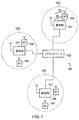
FIG. 1 is a schematic diagram depicting the basic functionality of a wireless communication network /
ネットワーク100は、1つのコアネットワーク102へ接続される複数の基地局101を含む。各基地局は、端末デバイス104との間でデータをその中で通信することができるカバレッジエリア103(すなわち、セル)を提供する。データは、基地局101から、自身のカバレッジエリア103内の端末デバイス104へ、無線ダウンリンクを介して送信される。データは、端末デバイス104から基地局101へ、無線アップリンクを介して送信される。コアネットワーク102は、端末デバイス104へ及び端末デバイス104からそれぞれの基地局101を介してデータをルーティングし、また、認証、モビリティ管理、課金などの機能を提供する。端末デバイスは、移動局、ユーザ機器(UE)、ユーザ端末、移動無線機などとも呼ばれ得る。基地局は、トランシーバ局/nodeB/e−NodeBなどとも呼ばれ得る。
The
3GPP定義のLTE(Long Term Evolution)アーキテクチャに従って構成されるモバイル通信システムなどのモバイル通信システムは、無線ダウンリンクのためには直交周波数分割多重(OFDM)ベースのインターフェイスを使用し(いわゆるOFDMA)、無線アップリンクのためにはシングルキャリア周波数分割多重ベースのインターフェイスを使用する(いわゆるSC−FDMA)。図2は、OFDMベースのLTEダウンリンク無線フレーム201を示す概略図である。LTEダウンリンク無線フレームは、(エンハンスドNodeBとして知られる)LTE基地局から送信され、10ミリ秒間続く。ダウンリンク無線フレームは10のサブフレームを含み、各サブフレームは1ミリ秒間続く。プライマリ同期信号(primary synchronisation signal(PSS))及びセカンダリ同期信号(secondary synchronisation signal(SSS))は、LTEフレームの第1のサブフレーム及び第6のサブフレーム内で送信される。物理ブロードキャストチャネル(physical broadcast channel(PBCH))は、LTEフレームの第1のサブフレーム内で送信される。
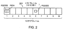
Mobile communication systems, such as mobile communication systems configured in accordance with 3GPP-defined LTE (Long Term Evolution) architecture, use orthogonal frequency division multiplexing (OFDM) based interfaces for radio downlink (so-called OFDMA) and wireless. For the uplink, a single carrier frequency division multiplexing based interface is used (so-called SC-FDMA). FIG. 2 is a schematic diagram illustrating an OFDM-based LTE
図3は、例示的な従来のダウンリンクLTEサブフレーム(この例では図2のフレーム内の第1の、すなわち最も左側のサブフレームに対応する)の構造を描いたグリッドの概略図である。サブフレームは、1ミリ秒の期間にわたって送信される予め定められた数のシンボルを含む。各シンボルは、ダウンリンク無線キャリアの帯域幅にわたって分散される予め定められた数の直交サブキャリアを含む。 3 is a schematic diagram of a grid depicting the structure of an exemplary conventional downlink LTE subframe (corresponding to the first, leftmost subframe in the frame of FIG. 2 in this example). A subframe includes a predetermined number of symbols transmitted over a 1 millisecond period. Each symbol includes a predetermined number of orthogonal subcarriers distributed over the bandwidth of the downlink radio carrier.
図3に示される例示的なサブフレームは、14のシンボル及び、20MHzの帯域幅にわたって散在する1200のサブキャリアを含む。LTEにおける送信のためのユーザデータの最小の割り当ては、1スロット(0.5サブフレーム)上で送信される12のサブキャリアを含むリソースブロックである。明確にするために、図3では、各個別のリソースエレメント(1つのリソースエレメントは、単一のサブキャリア上に単一のシンボルを含む)は示されておらず、代わりに、サブフレームのグリッド内の各個別のボックスは、1のシンボル上で送信される12のサブキャリアに相当する。 The exemplary subframe shown in FIG. 3 includes 14 symbols and 1200 subcarriers scattered across a 20 MHz bandwidth. The minimum allocation of user data for transmission in LTE is a resource block including 12 subcarriers transmitted on 1 slot (0.5 subframe). For clarity, FIG. 3 does not show each individual resource element (one resource element contains a single symbol on a single subcarrier); instead, a subframe grid Each individual box corresponds to 12 subcarriers transmitted on one symbol.
図3は、4つのLTE端末340、341、342、343のためのリソース割り当てを示す。例えば、第1のLTE端末(UE1)のためのリソース割り振り342は、12のサブキャリアの5つのブロック(すなわち、60のサブキャリア)にわたって延在し、第2のLTE端末(UE2)のためのリソース割り当て343は、12のサブキャリアの6つのブロックにわたって延在する、等である。
FIG. 3 shows resource allocation for four
制御チャネルデータは、サブフレームの最初のn個のシンボルを含む、サブフレームの(図3において点網掛けで示される)制御領域300内で送信される。ここでnは、3MHz以上のチャネル帯域幅については1から3のシンボルの間で可変であり、またnは、1.4MHzのチャネル帯域幅については2から4のシンボルの間で可変である。具体例を提供するために、以下の説明は、3MHz以上のチャネル帯域幅でのキャリアに関するものであり、よって、nの最大値は3になる。制御領域300内で送信されるデータは、物理ダウンリンク制御チャネル(physical downlink control channel(PDCCH))、物理制御フォーマットインジケータチャネル(physical control format indicator channel(PCFICH))及び物理HARQインジケータチャネル(physical HARQ indicator channel(PHICH))上で送信されるデータを含む。
Control channel data is transmitted in the control region 300 (shown as dotted shading in FIG. 3), including the first n symbols of the subframe. Here, n is variable between 1 and 3 symbols for a channel bandwidth of 3 MHz or more, and n is variable between 2 and 4 symbols for a channel bandwidth of 1.4 MHz. In order to provide a specific example, the following description relates to a carrier with a channel bandwidth of 3 MHz or higher, so the maximum value of n is 3. Data transmitted in the
PDCCHは、サブフレームのどのシンボル上のどのサブキャリアが特定のLTE端末に割り当てられているかを示す制御データを含む。このため、図3に示されるサブフレームの制御領域300内で送信されるPDCCHデータは、UE1には参照番号342によって識別されるリソースブロックが割り当てられていること、UE2には参照番号343によって識別されるリソースブロックが割り当てられていること、等を示す。
The PDCCH includes control data indicating which subcarrier on which symbol of the subframe is allocated to a specific LTE terminal. Therefore, in the PDCCH data transmitted in the
PCFICHは、制御領域のサイズ(すなわち、シンボル1個分から3個分)を示す制御データを含む。 The PCFICH includes control data indicating the size of the control area (that is, one to three symbols).
PHICHは、先に送信されたアップリンクデータがネットワークによって首尾よく受信されたか否かを示すHARQ(Hybrid Automatic Request)データを含む。 The PHICH includes HARQ (Hybrid Automatic Request) data indicating whether the previously transmitted uplink data has been successfully received by the network.
時間・周波数リソースグリッドの中央帯域310におけるシンボルは、プライマリ同期信号(PSS)、セカンダリ同期信号(SSS)及び物理ブロードキャストチャネル(PBCH)を含む情報の送信のために使用される。この中央帯域310は、典型的に、72のサブキャリアの幅(1.08MHzの送信帯域幅に相当する)である。PSS及びSSSは、一旦検出されるとLTE端末デバイスがフレームの同期を達成し及びダウンリンク信号を送信しているエンハンスドNodeBのセルIDを判定することを可能にする、同期信号である。PBCHは、LTE端末がセルに正しくアクセスするために使用するパラメータを含むマスタ情報ブロック(master information block(MIB))を含む、セルに関する情報を搬送する。物理ダウンリンク共有チャネル(physical downlink shared channel(PDSCH))上で個々のLTE端末へ送信されるデータは、そのサブフレームの他のリソースエレメントにおいて送信されることができる。
The symbols in the
図3は、システム情報を含みかつR344の帯域幅にわたって延在するPDSCHの領域も示す。従来のLTEフレームは、明確にするために図3には示されていないリファレンス信号も含む。 FIG. 3 also shows the region of PDSCH that contains system information and extends across the bandwidth of R344. A conventional LTE frame also includes a reference signal not shown in FIG. 3 for clarity.
図4は、図3に似た、多くの点で図3から理解される図である。しかしながら、図4は、複数(この場合は3つ)の仮想キャリア401、402、403(VC)がその中でサポートされるホストキャリアに対応するダウンリンク無線サブフレームを概略的に示している点で、図3と異なる。図4に概略的に示されているように、仮想キャリアには、参照しやすくするためにVC1、VC2及びVC3のラベルが付されている。図4に示される仮想キャリアの一般的な動作は、例えば上述の文献[2]から[11]のいずれかに記述されているような、先に提案されている方式に従ってよい。このため、各仮想キャリアは、ホストキャリアに関連付けられた送信リソースグリッド全体内の、所定の端末デバイス、例えばケイパビリティが低減されたマシンタイプ通信端末デバイス、と少なくとも一部の情報を通信するために使用され得る、ダウンリンク送信リソースの制限されたサブセットを表す。
FIG. 4 is similar to FIG. 3 and is understood from FIG. 3 in many respects. However, FIG. 4 schematically shows a downlink radio subframe in which multiple (in this case, three)
このため、従来の(すなわち、ケイパビリティが低減されていない)端末デバイスは、従来のLTE技術に従って、図4に示されているリソースグリッドの全帯域幅を使用してサポートされ得る。他方、低減ケイパビリティ端末デバイスのためのダウンリンク通信は、複数の仮想キャリアのうちその端末デバイスが割り当てられている1つの仮想キャリア内の送信リソースに制限され得る。 Thus, a conventional (ie, the capability is not reduced) terminal device can be supported using the full bandwidth of the resource grid shown in FIG. 4 according to conventional LTE technology. On the other hand, downlink communication for reduced capability terminal devices may be limited to transmission resources within one virtual carrier to which the terminal device is assigned among a plurality of virtual carriers.
いくつかの場合、(制御シグナリング及び上位レイヤ/ユーザプレーンデータを含む)低減ケイパビリティ端末デバイスのためのダウンリンク通信の全体が、例えば上述の文献[2]から[9]で提案されている原理に従って、複数の仮想キャリアのうち1つの仮想キャリアの送信リソース内で伝達されてよい。これは、例えば、ホストキャリアの全帯域幅を受信することができない(またそれ故に制御領域300の全体を受信することができない)端末デバイスにとって適切であり得る。 In some cases, the entire downlink communication for reduced capability terminal devices (including control signaling and higher layer / user plane data) is in accordance with the principles proposed in eg [2] to [9] above. The transmission resource of one virtual carrier among a plurality of virtual carriers may be transmitted. This may be appropriate, for example, for a terminal device that cannot receive the entire bandwidth of the host carrier (and therefore cannot receive the entire control region 300).
他の場合、低減ケイパビリティ端末デバイスは、ホストキャリアの全帯域幅を受信する(及びそれ故に制御領域300を受信し復号する)ことができ得るが、PDSCH領域の全体をバッファし復号する能力については制限され得るので、例えば上述の文献[10]及び[11]で提案されている「T型割り当て」の原理に従って、その端末デバイスが割り当てられている仮想キャリアにわたるダウンリンク送信リソースのサブセットのみをバッファし復号してもよい。 In other cases, the reduced capability terminal device may be able to receive the full bandwidth of the host carrier (and hence receive and decode the control region 300), but for the ability to buffer and decode the entire PDSCH region For example, according to the principle of “T-type allocation” proposed in the above-mentioned documents [10] and [11], only a subset of downlink transmission resources over the virtual carrier to which the terminal device is allocated is buffered. It may be decoded.
しかしながら、所与の実装において用いられる仮想キャリア動作の特定の方式にかかわらず、仮想キャリアを使用してサポートされるべき端末デバイスは、それが割り当てられている仮想キャリアのためにどの特定の制限された周波数レンジが使用されているのかを確認する必要がある。例えば、図4に示されるダウンリンクサブフレーム送信リソースグリッドのコンテキストにおいて仮想キャリア動作を使用してサポートされるべき低減ケイパビリティ端末デバイスは、仮想キャリアVC1、VC2又はVC3のうちどの仮想キャリア上でそれがサポートされるのかを確認しなければならない。上述したように、1つのアプローチは、基地局が、接続手続き中に専用のシグナリング交換を通じて、当該デバイスが割り当てられている仮想キャリアを低減ケイパビリティ端末デバイスに通知することである。しかしながら、やはり上に述べたように、これにより、シグナリングの複雑性が増し、制御シグナリングのオーバヘッドが増加する可能性がある。 However, regardless of the specific scheme of virtual carrier operation used in a given implementation, a terminal device to be supported using a virtual carrier is limited to which specific for the virtual carrier to which it is assigned. It is necessary to check whether the correct frequency range is used. For example, a reduced capability terminal device to be supported using virtual carrier operation in the context of the downlink subframe transmission resource grid shown in FIG. 4 is on which virtual carrier of virtual carrier VC1, VC2 or VC3 You must check if it is supported. As mentioned above, one approach is for the base station to inform the reduced capability terminal device of the virtual carrier to which it is assigned through a dedicated signaling exchange during the connection procedure. However, as also noted above, this can increase signaling complexity and potentially increase control signaling overhead.
図5は、本開示の一実施形態に従った通信システム500を概略的に示す。この例における通信システム500は、図4に概略的に示されているような複数の仮想キャリアをサポートするLTEタイプのアーキテクチャに概ね基づいている。通信システム500の動作の数多くの点は、既知であり理解されているため、簡略にするためにここでは詳細に説明しない。本明細書に具体的に説明されない通信システム500の動作面は、任意の既知の技術に従って、例えば仮想キャリア動作を組み込むために適宜変形が加えられた現行のLTE標準に従って、実装されてよい。そうした標準は、GB 2 487 906[2]、GB 2 487 908[3]、GB 2 487 780[4]、GB 2 488 513[5]、GB 2 487 757[6]、GB 2 487 909[7]、GB 2 487 907[8]、GB 2 487 782[9]、GB 2 497 743[10]及びGB 2 497 742[12]に開示されており、それらの内容全体が参照により本明細書に組み込まれる。
FIG. 5 schematically illustrates a
通信システム500は、無線ネットワーク部分に連結されるコアネットワーク部分(進化型(evolved)パケットコア)502を含む。無線ネットワーク部分は、複数の端末デバイスに連結される1つの基地局(evolved−nodeB)504を含む。この例では、2つの端末デバイス、すなわち、第1の端末デバイス506及び第2の端末デバイス508が示されている。もちろん、実際には、様々な通信セルにわたってより多数の端末デバイスにサービスする複数の基地局を無線ネットワーク部分が含み得ることが理解されるであろう。しかしながら、簡略にするため、図5では、単一の基地局及び2つの端末デバイスのみを示す。
従来のモバイル無線ネットワークと同様に、端末デバイス506、508は、基地局(トランシーバ局)504との間でデータを通信するように構成される。基地局は同様に、基地局504を介して通信システム500内の端末デバイスへのモバイル通信サービスのルーティング及び管理を行うように構成されているコアネットワーク部分内のサービングゲートウェイ(S−GW)(図示せず)へ通信可能に接続される。モビリティ管理及び接続性を維持する目的で、コアネットワーク部分502は、ホーム加入者サーバ(HSS)に記憶されている加入者情報に基づいて通信システム内で動作する端末デバイス506、508との拡張パケットサービス(EPS)接続を管理する、モビリティ管理エンティティ(図示せず)も含む。コアネットワーク内の他のネットワークコンポーネント(やはり簡略のために図示せず)は、ポリシー課金及びリソース機能(PCRF)と、コアネットワーク部分502から例えばインターネットといった外部パケットデータネットワークへの接続を提供するパケットデータネットワークゲートウェイ(PDN−GW)と、を含む。上述のように、図5に示される通信システム500の様々なエレメントの動作は、本明細書に記述されているように本開示の実施形態に従って機能性を提供するように変更される部分を除いては、例えば確立されている通信標準及び本明細書で挙げた参照文献に説明されている原理に従って、概ね従来どおりであってよい。
Similar to conventional mobile radio networks,
この例では、第1の端末デバイス506は、従来のやり方で基地局504と通信する従来のスマートフォンタイプの端末デバイスであると想定される。この従来型の端末デバイス506は、無線信号の送受信のためのトランシーバユニット506aと、デバイス506を制御するように構成されたプロセッサユニット506bと、を含む。プロセッサユニット506bは、無線通信システム内の機器のための従来のプログラミング/構成技術を使用して望まれる機能性を提供するように好適に構成/プログラムされるプロセッサユニットを含み得る。トランシーバユニット506a及びプロセッサユニット506bは、図5では別々のエレメントとして概略的に示されている。しかしながら、これらのユニットの機能性は、種々様々な方法で、例えば好適にプログラムされた単一の汎用コンピュータを又は好適に構成された特定用途向け集積回路(群)/回路構成を使用して、提供されることができることが理解されるであろう。理解されるように、従来型の端末デバイス506は、一般的に、その動作機能性に関連付けられた他の様々なエレメントを含む。
In this example, the first
この例では、第2の端末デバイス508は、基地局504と通信する際に本開示の実施形態に従って仮想キャリア(VC)モードで動作するように適合されたマシンタイプ通信(MTC)端末デバイス504であると想定される。上述のように、マシンタイプ通信端末デバイスは、いくつかの場合、典型的に、少量のデータを通信する半自律又は自律無線通信デバイスとして特徴付けられることができる。例として、いわゆるスマートメーターがあるが、当該メーターは、例えば、顧客の家に配置され、顧客が消費したガス、水道、電気などのユーティリティに関するデータを中央のMTCサーバへ周期的に情報を送り返す。MTCデバイスは、いくつかの点で、例えば遅延の観点から、比較的低いサービス品質(QoS)を有する比較的低い帯域幅の通信チャネルによってサポートされることができるデバイスであると見なされてよい。ここでは、図5内のMTC端末デバイス508がそのようなデバイスであると想定される。
In this example, the second
MTCデバイス508は、無線信号の送受信のためのトランシーバユニット508aと、MTCデバイス508を制御するように構成されたプロセッサユニット508bと、を含む。プロセッサユニット508bは、ここにさらに説明されるように、本開示のいくつかの実施形態に従って機能性を提供するための様々なサブユニット、例えばVC選択ユニット、を含み得る。これらのサブユニットは、別々のハードウェアエレメントとして、又は当該プロセッサユニットの適切に構成された機能群として、実現され得る。このため、プロセッサユニット508bは、無線通信システム内の機器のための従来のプログラミング/構成技術を使用して本明細書に記述されている望まれる機能性を提供するように好適に構成/プログラムされるプロセッサを含み得る。トランシーバユニット508a及びプロセッサユニット508bは、図5では表記しやすいように別々のエレメントとして概略的に示されている。しかしながら、これらのユニットの機能性は、種々様々な方法で、例えば、好適にプログラムされた単一の汎用コンピュータをもしくは好適に構成された特定用途向け集積回路(群)/回路構成を使用して、又は、望まれる機能性の様々なエレメントを提供するために複数の別々の回路/処理エレメントを使用して、提供されることができることが理解されるであろう。MTCデバイス508が、一般的に、確立されている無線通信技術に従って、その動作機能性に関連付けられた他の様々なエレメントを含むことは、理解されるであろう。
The
基地局504は、無線信号の送受信のためのトランシーバユニット504aと、本明細書に記述されているように本開示の実施形態に従って動作するように基地局504を制御するように構成されたプロセッサユニット504bと、を含む。プロセッサユニット506bもやはり、下にさらに説明されるように、本開示の実施形態に従って機能性を提供するための様々なサブユニット、例えばVC選択ユニット及びスケジューリングユニット、を含み得る。これらのサブユニットは、別々のハードウェアエレメントとして、又は当該プロセッサユニットの適切に構成された機能群として、実現され得る。このため、プロセッサユニット504bは、無線通信システム内の機器のための従来のプログラミング/構成技術を使用して本明細書に記述されている望まれる機能性を提供するように好適に構成/プログラムされるプロセッサを含み得る。トランシーバユニット504a及びプロセッサユニット504bは、図5では表記しやすいように別々のエレメントとして概略的に示されている。しかしながら、これらのユニットの機能性が、種々様々な方法で、例えば、好適にプログラムされた単一の汎用コンピュータをもしくは好適に構成された特定用途向け集積回路(群)/回路構成を使用して、又は、望まれる機能性の様々なエレメントを提供するために複数の別々の回路/処理エレメントを使用して、提供されることができることは、理解されるであろう。基地局504が、一般的に、確立されている無線通信技術に従って、その動作機能性に関連付けられた他の様々なエレメントを含むことは、理解されるであろう。
このため、基地局504は、従来型の端末デバイス506及び本開示の一実施形態に従った端末デバイス508の両方と、それぞれの通信リンク510、512上で、データを通信するように構成される。基地局504と従来型の端末デバイス506との間の通信のための通信リンク510は、ホストキャリアにより、(例えば、図4に概略的に示された送信リソースの全レンジを潜在的に利用して)サポートされる。基地局504とケイパビリティが低減されたMTC端末デバイス508との間の通信のための通信リンク512は、1つの仮想キャリアにより、(例えば、図4に概略的に示された複数の仮想キャリアのうち選択された1つの仮想キャリア内のリソースを利用して)サポートされる。MTC端末デバイス508と基地局504とが、本開示の実施形態に従って、MTC端末デバイス508との通信をサポートするためにどの仮想キャリア周波数が使用されるべきかについて一旦設定/合意すると、(すなわち、マシンタイプ通信端末デバイス508がその上でサポートされるべき1つの仮想キャリアを選択すると)、基地局504とMTC端末デバイス508との間の以降のデータ通信は、選択された仮想キャリア上で、先に提案されている仮想キャリア動作のための方式のいずれかに概ね従って動作し得る。例えば、端末デバイス508へ向けられる基地局504からの制御プレーンシグナリング及びユーザプレーンシグナリングがすべて仮想キャリアの帯域幅内で行われるように、MTC端末デバイス508は動作し得る。代替的に、端末デバイス508へ向けられる基地局504からの制御プレーンシグナリングは、図4に示された制御領域300の全帯域幅内で行われてもよく、上位レイヤデータ(ユーザプレーンデータ)は、選択された仮想キャリアの制限された帯域幅内で通信される。
Thus, the
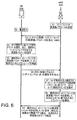
図6は、本開示のいくつかの実施形態に従った、図5に概略的に提示された端末デバイス508及び基地局504のための動作モードを概略的に示す、シグナリングのラダー図である。図6に示される動作モードは、仮想キャリアモードにおける基地局から端末デバイス508へのダウンリンク通信のために、基地局によって目下サポートされている利用可能な複数の仮想キャリアのうちどの仮想キャリアが使用されるべきかを、端末デバイス508及び基地局504が事実上独自に選択できるように構成されている。
FIG. 6 is a signaling ladder diagram schematically illustrating operating modes for the
このため、図6に示される第1のステップS1で、基地局504は、自身がサポートすべき複数の仮想キャリアについての構成パラメータを設定する。仮想キャリアについての構成パラメータは、例えば、仮想キャリアの数及び/又はそれらの周波数の指示を含み得る。仮想キャリアの周波数に関する構成情報を、様々な実装において特徴付けることができる多様な方法があることが理解されるであろう。例えば、特定の仮想キャリア(制限された周波数帯域)に関連付けられた周波数位置は、中央周波数及び帯域幅の指示によって、又は上位及び下位境界周波数によって、表され得る。仮想キャリアの帯域幅が、例えば1.4MHzで、固定/予め定義される実装では、仮想キャリアの周波数に関する構成情報は、ホストキャリアの周波数空間における仮想キャリアの位置を示す単一の周波数値(例えば、仮想キャリアが位置しているかどうかを示す中央周波数、又は下位又は上位の周波数)を含んでよい。
Therefore, in the first step S1 shown in FIG. 6, the
この例示的実装では、基地局は、仮想キャリア動作をサポートするために使用されるリソースをスケジューリングするにあたり高い柔軟性を有するものと想定される。このため、基地局は、目下のトラフィックの状況に基づいて、実装されるべき仮想キャリアの数、及びそれらの仮想キャリアが位置する周波数(並びに潜在的に、いくつかの例では、それらそれぞれの帯域幅)を選択するように構成され得る。例えば、目下のトラフィックの状況が、数多くの低減ケイパビリティ端末デバイスを基地局がサポートする必要があることを示している場合、目下のトラフィックの状況が、より少数の低減ケイパビリティ端末デバイスを基地局がサポートする必要があることを示している場合よりも、より多数の仮想キャリアが使用のために構成され得る。さらに、この特定の例示的実装における基地局504は、使用されるべき仮想キャリアについての周波数位置を決定するにあたり柔軟性を有するものと想定される。基地局は、従来技術に従ってこの決定を行ってよい。例えば、様々な周波数でのチャネル状態を考慮する。他の例示的実装では、基地局は、例えば、実装する仮想キャリアの数を選択することができ得るが、仮想キャリアが位置すべき周波数は、通信システム内で予め定義され得る。例えば、予め定義された周波数位置は、様々な数の仮想キャリアについて標準化され得る。
In this exemplary implementation, the base station is assumed to have a high degree of flexibility in scheduling resources used to support virtual carrier operation. Thus, based on the current traffic situation, the base station determines the number of virtual carriers to be implemented and the frequency at which those virtual carriers are located (and potentially, in some examples, their respective bandwidths). Width). For example, if the current traffic situation indicates that the base station needs to support a large number of reduced capability terminal devices, the current traffic situation supports a smaller number of reduced capability terminal devices. A greater number of virtual carriers may be configured for use than if it indicates that it needs to be done. Further, the
具体例のために、ここでは、ステップS1で基地局504は、自身が3つの仮想キャリアを図4にVC1、VC2及びVC3によって概略的に示されている周波数位置でサポートする、と決定するものと想定される。仮想キャリアの選択される数及び周波数を変化するトラフィックの状況に従って基地局が絶え間なく最適化することができるように、ステップS1は継続的に繰り返されてよい。代替的に、基地局によってサポートされるべき仮想キャリアについて設定される周波数パラメータは、比較的静的であってもよい。いくつかの例では、基地局のための仮想キャリア構成パラメータは固定され得る。例えば、それらのパラメータは、基地局の初期配備中に設定され及び固定され得る(例えば、関連の構成パラメータは無線通信システムのために予め定義され得る)。
For the sake of illustration, here, in step S1, the
ステップS2で、MTC端末デバイス508は、例えば端末デバイス508へ電源が投入されるのに応答して、基地局504に関連付けられた無線ネットワークへの初期アクセスを求める。いったん電源が投入されると、この例における端末デバイス508は、従来のLTEタイプのネットワークキャンプオン手続きを開始して、無線ネットワークへアクセスするのに必要なパラメータを取得する。このため、概ね従来の技術に従って、端末デバイス508は、基地局の無線フレーム構造と同期し、PBCH、PCFICHなどを復号し、よって、端末デバイス508は、既知の技術を使用して(すなわち、仮想キャリア動作をサポートするネットワークにおける、先に提案されている低減ケイパビリティ端末デバイスのキャンプオン手続きに従って)、システム情報(SI)を取得できる立場にある。
In step S2, the
このため、図6のステップS3に概略的に示されるように、基地局504は、BCCH(ブロードキャスト制御チャネル)上でシステム情報(SI)を送信し、これが、既知の技術に従って、端末デバイス508により、その通常のキャンプオン手続きの一部として受信される。
Thus, as schematically shown in step S3 of FIG. 6, the
しかしながら、本開示の所定の実施形態に従えば、基地局504によりブロードキャストされるシステム情報は、当該システム情報が(ステップS1で設定されたような)基地局によってサポートされる仮想キャリアについての周波数パラメータに関する追加情報を含んでいるという点で、LTEタイプのネットワーク内でブロードキャストされる従来のシステム情報と異なる。
However, according to certain embodiments of the present disclosure, the system information broadcast by
この特定のLTEベースの例では、この情報は、その他の点では従来通りであるシステム情報ブロック2(SIB2)のシグナリングにおいて伝達される、新たに定義されたパラメータを使用して伝達されるものと想定される。例えば、関連の構成パラメータを伝達するために、1つ以上の新しい情報エレメントが使用され得る。上述のように、例えば中央周波数及び帯域幅、上位及び下位境界周波数、想定された(すなわち、固定された)帯域幅での単一の周波数位置などの観点から、それぞれの仮想キャリアについてパラメータを特徴付け得る種々様々な方法がある。さらに、伝達されるべき情報を、様々な方法で特徴付けることができる。例えば、特定の周波数の観点から、又は予め定義された関連付けに従って周波数を識別するインデックス値の観点から、である。このため、情報を端末デバイスへ伝達する厳密な方法は、実装によって異なってよい。基地局によってサポートされる各仮想キャリアにつき、周波数の指示が提供される場合、仮想キャリアの合計数は、提供される周波数情報の量から判定されることができるため、システム情報内で別途伝達されることはないかも知れない。 In this particular LTE-based example, this information is communicated using newly defined parameters that are otherwise communicated in the conventional System Information Block 2 (SIB2) signaling. is assumed. For example, one or more new information elements can be used to convey relevant configuration parameters. As described above, features parameters for each virtual carrier in terms of, for example, center frequency and bandwidth, upper and lower boundary frequencies, a single frequency position in the assumed (ie, fixed) bandwidth, etc. There are a variety of methods that can be applied. Furthermore, the information to be communicated can be characterized in various ways. For example, from the perspective of a particular frequency, or from the perspective of an index value that identifies a frequency according to a predefined association. For this reason, the exact method of communicating information to the terminal device may vary depending on the implementation. For each virtual carrier supported by the base station, if a frequency indication is provided, the total number of virtual carriers can be determined from the amount of frequency information provided and is therefore communicated separately in the system information. It may not be.
このため、システム情報を、特にこの特定のLTEベースの例ではSIB2(システム情報ブロック2)を図6のステップS3で受信すると、端末デバイス508は、基地局によってサポートされる仮想キャリアについての関連の構成パラメータを認識する。特に、この例における端末デバイスは、基地局から受信されるシステム情報シグナリングを通じて、サポートされている仮想キャリアの数(NVC)、及びそれらそれぞれの周波数位置(F1、F2、…、FNVC)を通知される。例えば、図4に概略的に示されるこの例示的な実装を参照して、基地局によって送信されるシステム情報は、基地局が目下3つの仮想キャリア(すなわち、NVC=3)を中央周波数(VC1については)F1、(VC2については)F2及び(VC3については)F3でサポートしていることを示すように、本開示の一実施形態に従って適合される。この例示的な実装では、無線通信システムにおいてサポートされる仮想キャリアはすべて、1.4MHzといった周波数空間において予め定義された固定幅であると想定されるので、基地局から提供されるシステム情報は、それぞれの仮想キャリアの幅の指示を何ら提供する必要がない。
Thus, upon receiving system information, particularly SIB2 (system information block 2) in this particular LTE-based example, in step S3 of FIG. 6, the
ステップS4で、端末デバイス508(より特定的には、端末デバイスのプロセッサユニット508b)は、基地局によってサポートされている利用可能な複数の仮想キャリア(制限された帯域幅のキャリア)のうちの1つを、自身が基地局によりその上でサポートされるものと想定する仮想キャリアとして、選択する。端末デバイスはこれを、当該端末デバイスのための識別子に基づいて自律的に(すなわち、基地局からの特定の命令なしに)行う。この例では、この目的で端末デバイスによって使用される識別子は、当該デバイスに関連付けられた国際移動機加入者識別(international mobile subscriber identity(IMSI))番号である。IMSIは、端末デバイスによって使用される加入者識別モジュール(subscriber identity module(SIM))に永続的に関連付けられる番号である。このため、ステップS4で、端末デバイスは、基地局によってサポートされるNVC個の仮想キャリアのうちの1つを、端末デバイスのIDに依存する方法で選択する。
In step S4, the terminal device 508 (more specifically, the
この特定の例では、端末デバイス508は、識別子(IMSI)を基地局によってサポートされる仮想キャリアの数(NVC)で除算したときに得られる余り値を判定し、これをインデックス値(IND)として使用して、利用可能な仮想キャリア(VC1、VC2、VC3)のうちの1つを選択する。すなわち、端末デバイスは、次の式に従ってINDの値を決定する。
In this particular example, the
![]()
![]()
このため、基地局が3つの仮想キャリアをサポートする(すなわち、NVC=3)この例では、式1は、0、1又は2のINDの値を与える。その後、この値は、利用可能な複数の仮想キャリアのうちの1つを識別するインデックスとして使用される。例えば、仮想キャリアは、周波数が減少する順に(又は、その他の予め定義された順に)配列されていると考えられてよく、端末デバイスは、それらのうちの1つを、INDの値に基づいて選択してよい。特に、INDというインデックス値について、端末デバイスは、利用可能な仮想キャリアのリスト内で位置(IND+1)に関連付けられた仮想キャリアを選択してよい。すなわち、IND=0の場合、端末デバイスは、リスト内の第1の仮想キャリア(例えばVC1)を選択し、IND=1の場合、端末デバイスは、リスト内の第2の仮想キャリア(例えばVC2)を選択する、等である。
Thus, the base station supports three virtual carriers (ie, N VC = 3). In this example,
このため、ステップS4で、端末デバイス508のプロセッサユニット508bは、端末デバイスに関連付けられた識別子に基づいて、利用可能な仮想キャリア(VC1、VC2、VC3)のうちの1つを自律的に選択する。仮想キャリアのうちの1つを選んだ後、端末デバイスは、当該仮想キャリアについて対応する周波数パラメータを、例えばその中央周波数を、(例えば、基地局から受信した構成情報に基づいて、又は無線通信システムのために予め定義された関連付けから)設定することができる。本開示の実施形態に従えば、端末デバイスは、基地局からの以降の通信は、選択された仮想キャリアを使用して受信されるものと想定するように適合される。したがって、ステップS5で、端末デバイス508のトランシーバユニット508aは、基地局からの以降のダウンリンク通信を選択された仮想キャリア上で受信するように適切に構成される。図6の処理のこの面は、端末デバイスによってどの仮想キャリア周波数が使用されるべきかが一旦設定されれば、無線通信システムにおける仮想キャリア動作のための従来技術に従って実行され得る。
Thus, in step S4, the
このため、図6のステップS5の後には、端末デバイス508は、アタッチしたいと願う基地局によってどの仮想キャリアがサポートされているかに関する情報を受信し終わっており、複数の仮想キャリアのうち、基地局からダウンリンクUKをその中で受信することを見込む1つの仮想キャリアを選択し終わっており、また、そうした通信を受信するのに備えて自身のトランシーバを構成し終わっている。意義深いことに、これは、基地局と端末デバイスとの間でそのためのシグナリングを何ら行わずに達成されている。実際、図6に示されている例示的な方法に従えば、端末デバイスが基地局へ接続しようとしていることに基地局が気付きすらしないうちに、端末デバイスはこの段階に達している。
For this reason, after step S5 of FIG. 6, the
図6に示されるステップS6で、端末デバイス508は、基地局へのアクセスリクエスト、LTEタイプのアーキテクチャに基づくこの例では従来のRRC(無線リソース制御)接続リクエスト、を送信することによって、アタッチ手続きを継続する。確立されている技術に従って、接続確立のためのリクエストは、端末デバイスのための識別子を含み、また特にこの例では、端末デバイスのIMSIの指示を含む。ステップS6において接続リクエストシグナリングを受信すると、基地局は、そのリクエストが、本明細書に記述されている原理に従って手続きを実現する低減ケイパビリティ端末デバイスからのものであると判定するように構成される。これは、例えば、接続リクエストに含まれているデバイスタイプ分類子に基づくか、又は、端末デバイスのIMSIを、本開示の実施形態に従って方法を実現する低減ケイパビリティ端末デバイスとしてのそのステータスと結び付けるネットワーク側のルックアップテーブルに基づいてよい。
In step S6 shown in FIG. 6, the
ステップS6において端末デバイスから接続リクエストを受信すると、基地局は、ステップS4において選択された仮想キャリアを決定する際に端末デバイスによって使用された識別子を知らされるので、端末デバイスによりどの仮想キャリアが選択されたかを独自に判定することができる。このため、ステップS7で、基地局504(特に、そのプロセッサユニット504b)は、ステップS6において接続リクエストと関連して受信した端末デバイスの識別子を使用して、端末デバイスによるのと同じ方法で式1を適用することにより、端末デバイスによって選択された仮想キャリアを識別する。
Upon receiving a connection request from the terminal device in step S6, the base station is informed of the identifier used by the terminal device in determining the virtual carrier selected in step S4, so which virtual carrier is selected by the terminal device. It is possible to determine whether it has been done independently. Thus, in step S7, the base station 504 (in particular its
このため、ステップS7で、基地局504のプロセッサユニット504bは、接続セットアップシグナリングと関連して端末デバイスから受信した識別子に基づいて、端末デバイスによって選択された仮想キャリアを独自に判定する。仮想キャリアのうちの1つを選択すると、基地局は、その仮想キャリアについての対応する周波数パラメータ、例えばその中央周波数、を確認することができる。本開示の実施形態に従えば、基地局は、端末デバイスのための以降のダウンリンク通信が、選択された仮想キャリアを使用して実行されねばならない(すなわち、選択された仮想キャリアが、端末デバイスがダウンリンクリソースを割り当てられるべき仮想キャリアである)と想定するように適合される。
Thus, in step S7, the
したがって、ステップS8で、基地局504のトランシーバユニット504aは、選択された仮想キャリア上で端末デバイスへダウンリンク通信を送信するように適切に構成される(実際には、この構成は、端末デバイスとの以降の通信をスケジュールするためにどの仮想キャリアを使用すべきかの指示を記憶する基地局のスケジューリングユニットを単に要するものであり得る)。図6の処理のこの局面は、所与の端末デバイスのためにどの仮想キャリアが使用されるべきかが一旦設定されれば(すなわち、端末デバイスが仮想キャリアへ一旦割り当てられれば)、無線通信システムにおける仮想キャリア動作のための従来技術に従って実行され得る。
Accordingly, in step S8, the
このため、図6のステップS8の後には、端末デバイス508及び基地局504は両方とも、利用可能な複数の仮想キャリアのうち、基地局504と端末デバイス508との間の以降のダウンリンク通信のために使用されるべき、選択された1つの仮想キャリアを独自に判定し終わっている。意義深いことに、これは、基地局と端末デバイスとの間でそのための追加のシグナリングが何ら交換されることなく達成されている。
For this reason, after step S8 of FIG. 6, both the
端末デバイス508及び基地局504が、本開示の実施形態に従って使用されるべき仮想キャリアを一旦独自に設定/選択すれば、無線通信システム内の以降の動作は、従来の仮想キャリア技術に従って行われてよい。このため、図6でステップS9に概略的に示されるように、基地局504と端末デバイス508との間の以降の通信は、仮想キャリア/制限された帯域幅動作のための従来の技術に従って進行してよい。
Once
以降の仮想キャリア動作は、先に提案されている技術のうちいずれに従ってもよい。例えば、ステップS9に示されているVC動作は、選択された仮想キャリア(制限された周波数帯域)内で端末デバイスによって受信されるダウンリンク通信がユーザプレーンデータ及び制御プレーンデータの両方を含み、制御プレーンデータが、仮想キャリア上の、端末デバイスについてのユーザプレーンデータのためのリソース割り当ての指示を含む、参照文献[2]から[9]に記述されているようなアプローチに従ってよい。他の例では、ステップS9に示されているVC動作は、選択された仮想キャリア内で端末デバイスによって受信されるダウンリンク通信がユーザプレーンデータを含むのに対し、ユーザプレーンデータのための仮想キャリア上のリソース割り当ての指示を含む制御プレーンデータは選択された仮想キャリア外の周波数にわたる通信で(例えば、システム周波数帯域幅にわたる制御領域内で)受信される、参照文献[10]及び[11]に記述されているような「T型割り当て」アプローチに従ってもよい。仮想キャリア動作の他のモードも同様に採用することができる。 Subsequent virtual carrier operations may follow any of the previously proposed techniques. For example, the VC operation shown in step S9 is that the downlink communication received by the terminal device in the selected virtual carrier (limited frequency band) includes both user plane data and control plane data. The plane data may follow an approach as described in references [2] to [9] including instructions for resource allocation for user plane data for the terminal device on the virtual carrier. In another example, the VC operation shown in step S9 is a virtual carrier for user plane data, whereas a downlink communication received by a terminal device in a selected virtual carrier includes user plane data. Control plane data including the above resource allocation indications is received in references [10] and [11], which are received in communication over frequencies outside the selected virtual carrier (eg, within a control region over the system frequency bandwidth). A “T-assignment” approach as described may be followed. Other modes of virtual carrier operation can be employed as well.
このため、図6に概略的に示されているような本開示の所定の実施形態に従えば、低減ケイパビリティ端末デバイス508及び基地局504は、無線通信システムにおいて通常交換されるシグナリングを超えた専用のシグナリングをそれらの間で何ら交換する必要なしに、ダウンリンク通信のために使用されるべき仮想キャリアの周波数特性に関して、事実上合意に達し得る。
Thus, according to certain embodiments of the present disclosure as schematically illustrated in FIG. 6, reduced
端末デバイス508及び基地局504についてのこれらの動作方法が、本開示の所定の実施形態に従ったいくつかの例示的な実装にすぎないことは、理解されるであろう。上で説明し及び図6に示したアプローチに対する変更案及び修正案は、本開示の所定の実施形態の他の例示的実装に従って採用されることができる。
It will be appreciated that these methods of operation for
例えば、いくつかの例示的実装において、図6に示されるステップに相当するステップが異なる順序で実行され得ることは、理解されるであろう。例えば、端末デバイスが複数の利用可能な仮想キャリアから1つの仮想キャリアを選択するステップ(図6におけるステップS4)及びそのトランシーバを適切に構成するステップ(図6におけるステップS5)は、端末デバイスがRRC接続リクエストを開始するステップ(図6におけるステップS6)の後でも、同様に実行されることができる。 For example, it will be appreciated that in some exemplary implementations, steps corresponding to those shown in FIG. 6 may be performed in a different order. For example, when the terminal device selects one virtual carrier from a plurality of available virtual carriers (step S4 in FIG. 6) and appropriately configures its transceiver (step S5 in FIG. 6), the terminal device performs RRC. Even after the step of starting the connection request (step S6 in FIG. 6), it can be executed similarly.
いくつかの例示的実装において、仮想キャリアについての構成パラメータが無線通信システムのために予め定義され得ることも、理解されるであろう。例えば、基地局が特定の周波数位置で4つの仮想キャリアをサポートすることが、予め定められ得る。この場合、端末デバイスは、そのIDに基づいて使用する仮想キャリアを選択する際に、サポートされている仮想キャリアに関して構成パラメータを基地局から受信する必要なしに、この予め定義された情報を考慮するように適合され得る。すなわち、いくつかの実装において、(図6のステップS3に概略的に示されているような)初期アクセス手続き中に基地局から端末デバイスへ通信されるシステム情報は、仮想キャリアについての構成パラメータに関する情報を何ら含まない従来のものであってよい。代わりに、図6のステップS4に相当するステップにおいて仮想キャリアを選択することを可能にするために、端末デバイスは単に、予め定義された構成パラメータに関する関連の情報で予め構成される。 It will also be appreciated that in some exemplary implementations, configuration parameters for the virtual carrier may be predefined for the wireless communication system. For example, it may be predetermined that the base station supports four virtual carriers at a particular frequency location. In this case, the terminal device considers this predefined information without having to receive configuration parameters from the base station regarding supported virtual carriers when selecting a virtual carrier to use based on its ID. Can be adapted as such. That is, in some implementations, the system information communicated from the base station to the terminal device during the initial access procedure (as schematically shown in step S3 of FIG. 6) relates to the configuration parameters for the virtual carrier. It may be conventional without any information. Instead, in order to be able to select a virtual carrier in the step corresponding to step S4 of FIG. 6, the terminal device is simply preconfigured with relevant information regarding the predefined configuration parameters.
他の例では、選択された仮想キャリアの判定は、端末デバイスのための異なる識別子に基づいてよい。例えば、端末デバイスのためのIMSIを使用するのではなく、セル−無線ネットワーク一時識別子(cell-radio network temporary identifier(C−RNTI))といった、ネットワークから得られる端末デバイスのための一時識別子を使用してもよい。しかしながら、これには、例えば基地局が端末デバイスへC−RNTIを割り振るために、選択された仮想キャリアが合意されるまでに基地局と端末デバイスとの間である程度の専用通信を実行する必要があることは、理解されるであろう。 In other examples, the determination of the selected virtual carrier may be based on a different identifier for the terminal device. For example, rather than using IMSI for the terminal device, use a temporary identifier for the terminal device obtained from the network, such as a cell-radio network temporary identifier (C-RNTI). May be. However, this requires that some dedicated communication be performed between the base station and the terminal device before the selected virtual carrier is agreed, eg, for the base station to allocate C-RNTI to the terminal device. It will be understood that there is.
さらに、いくつかの例では、仮想キャリアを選択するプロセスが2回以上実行され得ることは、理解されるであろう。例えば、端末デバイスに最初に電源が投入されると、端末デバイスは最初に、上述の原理に従って1つの仮想キャリアを選択し得る。しかしながら、基地局はその後、ケイパビリティが低減されたデバイスをサポートする必要性における変化(例えば、仮想キャリアサポートを必要とするケイパビリティが低減されたデバイスの数の増加又は減少)に、サポートされている仮想キャリアの数を変更することによって対処せねばならないと、判断し得る。このため、基地局は、ブロードキャストされているシステム情報を、その仮想キャリア構成パラメータにおける変更を反映するために、更新し得る。このため、システム情報における更新を認識する端末デバイスは、図6に示されるステップS4及びS5を事実上繰り返し得るのに対し、基地局も同様に、図6に示されるステップS7及びS8に相当するステップを事実上繰り返す。これにより、新たに選択された仮想キャリア上で引き続きVC動作が可能になる。 Further, it will be appreciated that in some examples, the process of selecting a virtual carrier may be performed more than once. For example, when the terminal device is first powered on, the terminal device may initially select one virtual carrier according to the principles described above. However, the base station may subsequently be supported by changes in the need to support devices with reduced capabilities (eg, increasing or decreasing the number of devices with reduced capabilities that require virtual carrier support). It can be determined that it must be dealt with by changing the number of carriers. Thus, the base station can update the broadcast system information to reflect changes in its virtual carrier configuration parameters. For this reason, the terminal device that recognizes the update in the system information can effectively repeat steps S4 and S5 shown in FIG. 6, while the base station similarly corresponds to steps S7 and S8 shown in FIG. Virtually repeat the steps. As a result, the VC operation can be continued on the newly selected virtual carrier.
かくして、システム周波数帯域幅(ホストキャリア)にわたり、またシステム周波数帯域幅内でシステム周波数帯域幅よりも狭い複数の制限された周波数帯域(仮想キャリア)内での基地局から少なくともいくつかの端末デバイスへの少なくとも一部の通信をサポートする無線インターフェイスを使用してダウンリンク通信がなされる、無線通信システムについて説明してきた。端末デバイスは、無線インターフェイスへ当該端末デバイスがアクセスしようとする初期接続手続き中に、端末デバイスのID、例えばIMSIの指示を、基地局へ伝達する。端末デバイス及び基地局は両方とも、複数の制限された周波数帯域の中から1つの選択され制限された周波数帯域を、端末デバイスのIDに基づいて同じ方法で判定する。このため、端末デバイス及び基地局は、同じ制限された周波数帯域を選択し、したがって、それらの間で当該選択され制限された周波数帯域内でダウンリンク通信が可能になるように、それらそれぞれのトランシーバを構成することができる。 Thus, from a base station to at least some terminal devices over a system frequency bandwidth (host carrier) and within a plurality of restricted frequency bands (virtual carriers) within the system frequency bandwidth and narrower than the system frequency bandwidth A wireless communication system has been described in which downlink communication is performed using a wireless interface that supports at least some of the communication. The terminal device transmits an instruction of the terminal device ID, for example, IMSI, to the base station during an initial connection procedure in which the terminal device tries to access the wireless interface. Both the terminal device and the base station determine one selected restricted frequency band from the plurality of restricted frequency bands in the same manner based on the ID of the terminal device. Thus, the terminal device and the base station select the same restricted frequency band, and therefore their respective transceivers so that downlink communication is possible within the selected restricted frequency band between them. Can be configured.
本発明のさらなる具体的な及び好ましい局面については、添付の独立請求項及び従属請求項に記述される。従属請求項の特徴は、請求の範囲において明示的に述べられている組み合わせ以外の組み合わせで、独立請求項の特徴と組み合わせられ得ることは、理解されるであろう。 Further specific and preferred aspects of the invention are set out in the accompanying independent and dependent claims. It will be understood that the features of the dependent claims may be combined with the features of the independent claims in combinations other than those explicitly set forth in the claims.
よって、以上の説明は、本発明の単に例示的な実施形態を開示し記述したものである。当業者には理解されるように、本発明は、その思想からも本質的な特徴からも逸脱することなく、他の特定の形で実施されてよい。したがって、本発明の開示は、例示を意図するものであって、本発明の範囲及びその他の特許請求の範囲を限定するものではない。本開示は、本明細書における教示の容易に識別可能なあらゆる変形を含めて、以上の請求項の用語の範囲を、発明性のある主題が公開されることのないように、部分的に定義する。 Thus, the foregoing description discloses and describes merely exemplary embodiments of the invention. As will be appreciated by those skilled in the art, the present invention may be embodied in other specific forms without departing from its spirit or essential characteristics. Accordingly, the disclosure of the present invention is intended to be illustrative and is not intended to limit the scope of the invention or other claims. This disclosure, including any readily identifiable variation of the teachings herein, partially defines the scope of the terms of the following claims so that the inventive subject matter is not disclosed. To do.
本開示のいくつかのそれぞれの特徴は、次の2つのグループの番号付きパラグラフによって定義される。 Some respective features of the present disclosure are defined by the following two groups of numbered paragraphs.
番号付きパラグラフの第1のグループ:
1. システム周波数帯域幅にわたり、またシステム周波数帯域幅内でかつシステム周波数帯域幅よりも狭い複数の制限された周波数帯域内での少なくともいくつかの端末デバイスとの少なくとも一部の通信をサポートする無線インターフェイスを使用するダウンリンク通信が基地局によってなされる無線通信システムにおける端末デバイスの動作方法であって、当該方法は、
端末デバイスのための識別子に基づいて複数の制限された周波数帯域の中から1つの制限された周波数帯域を選択することと、
選択され制限された周波数帯域内で基地局からダウンリンク通信を受信するように端末デバイスを構成することと、を含む方法。
First group of numbered paragraphs:
1. A radio interface that supports at least some communication with at least some terminal devices over a system frequency bandwidth and within a plurality of restricted frequency bands within and less than the system frequency bandwidth; A method of operating a terminal device in a wireless communication system in which downlink communication to be used is performed by a base station, the method comprising:
Selecting one restricted frequency band from among a plurality of restricted frequency bands based on an identifier for the terminal device;
Configuring a terminal device to receive downlink communications from a base station within a selected restricted frequency band.
2. 端末デバイスのための識別子は、端末デバイスに関連付けられた国際移動機加入者識別(International Mobile Subscriber Identity(IMSI))を含む、条項1の方法。
2. The method of
3. 選択され制限された周波数帯域は、端末デバイスのための識別子に関連付けられた数値を基地局によってサポートされる複数の制限された周波数帯域の数で除算したときに得られる余り値から判定される、条項1又は2の方法。
3. The selected restricted frequency band is determined from a remainder value obtained when dividing the numerical value associated with the identifier for the terminal device by the number of restricted frequency bands supported by the base station,
4. 端末デバイスは、基地局によってサポートされる複数の制限された周波数帯域に関する構成情報を、基地局から受信されるシステム情報から設定することをさらに含む、条項1から3のいずれかの方法。 4). 4. The method of any of clauses 1-3, further comprising the terminal device configuring configuration information for a plurality of restricted frequency bands supported by the base station from system information received from the base station.
5. 構成情報は、基地局によってサポートされる複数の制限された周波数帯域の数の指示及び/又は制限された周波数帯域についての周波数の指示を含む、条項4の方法。
5. The method of
6. 端末デバイスは、基地局によってサポートされる複数の制限された周波数帯域に関する構成情報を、無線インターフェイス上での端末デバイスのための初期接続手続きより前に又はその手続き中に基地局から受信される情報から設定することをさらに含む、条項1から5のいずれかの方法。 6). The terminal device receives configuration information regarding a plurality of restricted frequency bands supported by the base station from the base station before or during the initial connection procedure for the terminal device over the radio interface. The method of any of clauses 1-5, further comprising setting from:
7. 構成情報は、基地局によってサポートされる複数の制限された周波数帯域の数の指示及び/又は制限された周波数帯域についての周波数の指示を含む、条項6の方法。
7). The method of
8. 基地局によってサポートされる複数の制限された周波数帯域に関する構成情報は、無線通信システムのために予め定義される、条項1から7のいずれかの方法。 8). 8. The method of any of clauses 1-7, wherein configuration information regarding a plurality of restricted frequency bands supported by a base station is predefined for a wireless communication system.
9. 構成情報は、基地局によってサポートされる複数の制限された周波数帯域の数の指示及び/又は制限された周波数帯域についての周波数の指示を含む、条項8の方法。
9. 9. The method of
10. 選択され制限された周波数帯域内で端末デバイスによって受信されるダウンリンク通信は、ユーザプレーンデータ及び制御プレーンデータを含み、制御プレーンデータは、ユーザプレーンデータを通信するために使用されるべき、選択され制限された周波数帯域内のリソースの指示を含む、条項1から9のいずれかの方法。
10. Downlink communication received by the terminal device within the selected restricted frequency band includes user plane data and control plane data, and the control plane data is selected to be used to communicate user plane data. 10. The method of any of
11. 選択され制限された周波数帯域内で端末デバイスによって受信されるダウンリンク通信は、ユーザプレーンデータを含み、当該方法は、端末デバイスが、システム周波数帯域幅の全域からの周波数リソース上で制御プレーンデータを受信することをさらに含み、制御プレーンデータは、ユーザプレーンデータを通信するために使用されるべき、選択され制限された周波数帯域内のリソースの指示を含む、条項1から10のいずれかの方法。 11. The downlink communication received by the terminal device within the selected and restricted frequency band includes user plane data, and the method allows the terminal device to transmit control plane data on frequency resources from across the system frequency bandwidth. 11. The method of any of clauses 1-10, further comprising receiving, wherein the control plane data includes an indication of resources in the selected restricted frequency band to be used to communicate user plane data.
12. 当該方法は、端末デバイスのための識別子の指示を端末デバイスから基地局へ伝達することをさらに含む、条項1から12のいずれかの方法。 12 13. The method of any of clauses 1-12, further comprising communicating an indication of an identifier for the terminal device from the terminal device to the base station.
13. 端末デバイスのための識別子の指示は、無線インターフェイス上での端末デバイスのための初期接続手続きより前に又はその手続き中に端末デバイスから基地局へ伝達される、条項12の方法。
13. 13. The method of
14. 端末デバイスのための識別子の指示は、無線リソース制御(RRC)接続リクエストのシグナリングと関連して伝達される、条項12の方法。
14 The method of
15. システム周波数帯域幅にわたり、またシステム周波数帯域幅内でかつシステム周波数帯域幅よりも狭い複数の制限された周波数帯域内での少なくともいくつかの端末デバイスとの少なくとも一部の通信をサポートする無線インターフェイスを使用するダウンリンク通信が基地局によってなされる無線通信システムにおいて使用される端末デバイスであって、当該端末デバイスはプロセッサユニットとトランシーバユニットとを含み、当該プロセッサユニットは、端末デバイスのための識別子に基づいて複数の制限された周波数帯域の中から1つの制限された周波数帯域を選択するように、及び、選択され制限された周波数帯域内で基地局からダウンリンク通信を受信するようにトランシーバユニットを構成するように構成される、端末デバイス。 15. A radio interface that supports at least some communication with at least some terminal devices over a system frequency bandwidth and within a plurality of restricted frequency bands within and less than the system frequency bandwidth; A terminal device used in a wireless communication system in which downlink communication to be used is performed by a base station, the terminal device including a processor unit and a transceiver unit, the processor unit based on an identifier for the terminal device Configuring the transceiver unit to select one restricted frequency band from a plurality of restricted frequency bands and to receive downlink communication from the base station within the selected restricted frequency band Configured to be a terminal device .
番号付きパラグラフの第2のグループ:
1. システム周波数帯域幅にわたり、またシステム周波数帯域幅内でかつシステム周波数帯域幅よりも狭い複数の制限された周波数帯域内での少なくともいくつかの端末デバイスとの少なくとも一部の通信をサポートする無線インターフェイスを使用するダウンリンク通信が基地局によってなされる無線通信システムにおける基地局の動作方法であって、当該方法は、
端末デバイスのための識別子に基づいて複数の制限された周波数帯域の中から端末デバイスのためのダウンリンク通信のために使用されるべき1つの制限された周波数帯域を選択することと、
選択され制限された周波数帯域内で端末デバイスへダウンリンク通信を送信することと、を含む方法。
Second group of numbered paragraphs:
1. A radio interface that supports at least some communication with at least some terminal devices over a system frequency bandwidth and within a plurality of restricted frequency bands within and less than the system frequency bandwidth; A method of operating a base station in a wireless communication system in which downlink communication to be used is performed by the base station, the method comprising:
Selecting one restricted frequency band to be used for downlink communication for the terminal device from among a plurality of restricted frequency bands based on the identifier for the terminal device;
Transmitting a downlink communication to a terminal device within a selected and restricted frequency band.
2. 端末デバイスのための識別子は、端末デバイスに関連付けられた国際移動機加入者識別(International Mobile Subscriber Identity(IMSI))を含む、条項1の方法。
2. The method of
3. 選択され制限された周波数帯域は、端末デバイスのための識別子に関連付けられた数値を基地局によってサポートされる複数の制限された周波数帯域の数で除算したときに得られる余り値から判定される、条項1又は2の方法。
3. The selected restricted frequency band is determined from a remainder value obtained when dividing the numerical value associated with the identifier for the terminal device by the number of restricted frequency bands supported by the base station,
4. 基地局によってサポートされる複数の制限された周波数帯域に関する構成情報を、基地局によって送信されるシステム情報内で端末デバイスへ伝達することをさらに含む、条項1から3のいずれかの方法。 4). 4. The method of any of clauses 1-3, further comprising communicating configuration information regarding a plurality of restricted frequency bands supported by the base station to the terminal device in system information transmitted by the base station.
5. 構成情報は、基地局によってサポートされる複数の制限された周波数帯域の数の指示及び/又は制限された周波数帯域についての周波数の指示を含む、条項4の方法。
5. The method of
6. 基地局によってサポートされる複数の制限された周波数帯域に関する構成情報を、無線インターフェイス上での端末デバイスのための初期接続手続きより前に又はその手続き中に端末デバイスへ伝達することをさらに含む、条項1から5のいずれかの方法。
6). Further comprising communicating configuration information regarding a plurality of restricted frequency bands supported by the base station to the terminal device prior to or during the initial connection procedure for the terminal device over the wireless interface. One of the
7. 構成情報は、基地局によってサポートされる複数の制限された周波数帯域の数の指示及び/又は制限された周波数帯域についての周波数の指示を含む、条項6の方法。
7). The method of
8. 基地局によってサポートされる複数の制限された周波数帯域に関する構成情報は、無線通信システムのために予め定義される、条項1から7のいずれかの方法。 8). 8. The method of any of clauses 1-7, wherein configuration information regarding a plurality of restricted frequency bands supported by a base station is predefined for a wireless communication system.
9. 構成情報は、基地局によってサポートされる複数の制限された周波数帯域の数の指示及び/又は制限された周波数帯域についての周波数の指示を含む、条項8の方法。
9. 9. The method of
10. 選択され制限された周波数帯域内で端末デバイスへ送信されるダウンリンク通信は、ユーザプレーンデータ及び制御プレーンデータを含み、制御プレーンデータは、ユーザプレーンデータを通信するために使用されるべき、選択され制限された周波数帯域内のリソースの指示を含む、条項1から9のいずれかの方法。
10. Downlink communication transmitted to the terminal device within the selected restricted frequency band includes user plane data and control plane data, and the control plane data is selected to be used to communicate user plane data. 10. The method of any of
11. 選択され制限された周波数帯域内で端末デバイスへ送信されるダウンリンク通信は、ユーザプレーンデータを含み、当該方法は、システム周波数帯域幅の全域からの周波数リソース上で制御プレーンデータを端末デバイスへ送信することをさらに含み、制御プレーンデータは、ユーザプレーンデータを通信するために使用されるべき、選択され制限された周波数帯域内のリソースの指示を含む、条項1から10のいずれかの方法。 11. The downlink communication transmitted to the terminal device within the selected and restricted frequency band includes user plane data, and the method transmits control plane data to the terminal device on frequency resources from across the system frequency bandwidth. 11. The method of any of clauses 1-10, further comprising: the control plane data includes an indication of resources in the selected restricted frequency band to be used to communicate user plane data.
12. 当該方法は、端末デバイスのための識別子の指示を端末デバイスから受信することをさらに含む、条項1から11のいずれかの方法。 12 12. The method of any of clauses 1-11, further comprising receiving an indication of an identifier for the terminal device from the terminal device.
13. 端末デバイスのための識別子の指示は、無線インターフェイス上での端末デバイスのための初期接続手続きより前に又はその手続き中に端末デバイスから受信される、条項12の方法。
13. 13. The method of
14. 端末デバイスのための識別子の指示は、無線リソース制御(RRC)接続リクエストのシグナリングと関連して端末デバイスから受信される、条項12の方法。
14 13. The method of
15. システム周波数帯域幅にわたり、またシステム周波数帯域幅内でかつシステム周波数帯域幅よりも狭い複数の制限された周波数帯域内での少なくともいくつかの端末デバイスとの少なくとも一部の通信をサポートする無線インターフェイスを使用するダウンリンク通信が基地局によってなされる無線通信システムにおいて使用される基地局であって、当該基地局はプロセッサユニットとトランシーバユニットとを含み、当該プロセッサユニットは、端末デバイスのための識別子に基づいて複数の制限された周波数帯域の中から端末デバイスとのダウンリンク通信のために使用されるべき1つの制限された周波数帯域を選択するように、及び、選択され制限された周波数帯域内で端末デバイスへダウンリンク通信を送信するようにトランシーバユニットを構成するように構成される、基地局。 15. A radio interface that supports at least some communication with at least some terminal devices over a system frequency bandwidth and within a plurality of restricted frequency bands within and less than the system frequency bandwidth; A base station used in a wireless communication system in which downlink communication to be used is performed by a base station, the base station including a processor unit and a transceiver unit, the processor unit based on an identifier for a terminal device Selecting one restricted frequency band to be used for downlink communication with the terminal device from among the plurality of restricted frequency bands, and within the selected restricted frequency band Transceiver to send downlink communication to the device Configured to constitute a knit, a base station.
参照文献
[1] ETSI TS 122 368 V10.530(2011−07)/3GPP TS 22.368 version 10.5.0 Release 10)
[2] GB 2 487 906(英国特許出願GB1101970.0)
[3] GB 2 487 908(英国特許出願GB1101981.7)
[4] GB 2 487 780(英国特許出願GB1101966.8)
[5] GB 2 488 513(英国特許出願GB1101983.3)
[6] GB 2 487 757(英国特許出願GB1101853.8)
[7] GB 2 487 909(英国特許出願GB1101982.5)
[8] GB 2 487 907(英国特許出願GB1101980.9)
[9] GB 2 487 782(英国特許出願GB1101972.6)
[10] GB 2 497 743(英国特許出願GB1121767.6)
[11] GB 2 497 742(英国特許出願GB1121766.8)
[12] Holma H. and Toskala A、“LTE for UMTS OFDMA and SC-FDMA based radio access”、John Wiley and Sons、2009
References [1] ETSI TS 122 368 V10.530 (2011-07) / 3GPP TS 22.368 version 10.5.0 Release 10)
[2]
[3]
[4]
[5]
[6]
[7]
[8]
[9]
[10]
[11]
[12] Holma H. and Toskala A, “LTE for UMTS OFDMA and SC-FDMA based radio access”, John Wiley and Sons, 2009
Claims (10)
前記端末デバイスのための国際移動機加入者識別(International Mobile Subscriber Identity(IMSI))を引数とする所定の関数により生成される値に基づいて前記複数の制限された周波数帯域の中から1つの制限された周波数帯域を選択することと、
前記選択され制限された周波数帯域内で前記基地局からダウンリンク通信を受信するように前記端末デバイスを構成することと、を含み、
前記端末デバイスは、前記基地局から、サポートされている制限された周波数帯域の数及び前記制限された周波数帯域の周波数位置を受信し、
前記所定の関数は、前記端末デバイスの前記IMSIを、前記複数の制限された周波数帯域の数で除算した余りとして前記値を生成する方法。 A method of operating a terminal device in a wireless communication system, wherein downlink communication is performed by a base station using a wireless interface over a system frequency bandwidth, and is within the system frequency bandwidth and narrower than the system frequency bandwidth Supporting communication with at least some terminal devices within a plurality of restricted frequency bands, the method comprising:
One restriction from among the plurality of restricted frequency bands based on a value generated by a predetermined function having an argument of an International Mobile Subscriber Identity (IMSI) for the terminal device Selecting a selected frequency band;
Configuring the terminal device to receive downlink communications from the base station within the selected restricted frequency band; and
It said terminal device from the base station, receives the number and frequency position of the limited frequency band of the limited frequency band is supported,
The predetermined function generates the value as a remainder obtained by dividing the IMSI of the terminal device by the number of the plurality of restricted frequency bands.
前記端末デバイスはプロセッサユニットとトランシーバユニットとを含み、前記プロセッサユニットは、前記端末デバイスのための国際移動機加入者識別(International Mobile Subscriber Identity(IMSI))を引数とする所定の関数により生成される値に基づいて前記複数の制限された周波数帯域の中から1つの制限された周波数帯域を選択するように、及び、前記選択され制限された周波数帯域内で前記基地局からダウンリンク通信を受信するように前記トランシーバユニットを構成するように構成され、前記前記トランシーバユニットは、前記基地局から、サポートされている制限された周波数帯域の数及び前記制限された周波数帯域の周波数位置を受信し、前記所定の関数は、前記端末デバイスの前記IMSIを、前記複数の制限された周波数帯域の数で除算した余りとして前記値を生成する、端末デバイス。
A terminal device used in a wireless communication system in which downlink communication using a radio interface is performed by a base station, wherein downlink communication is performed by the base station using a radio interface over a system frequency bandwidth, and the system Supports communication with at least some terminal devices within a plurality of restricted frequency bands within a frequency bandwidth and narrower than the system frequency bandwidth;
The terminal device includes a processor unit and a transceiver unit, and the processor unit is generated by a predetermined function having an argument of an international mobile subscriber identity (IMSI) for the terminal device. Selecting one restricted frequency band from among the plurality of restricted frequency bands based on a value, and receiving a downlink communication from the base station within the selected restricted frequency band The transceiver unit is configured to receive a number of supported limited frequency bands and a frequency position of the limited frequency band from the base station, and A predetermined function is to calculate the IMSI of the terminal device to the plurality of limited frequencies. A terminal device that generates the value as a remainder divided by the number of several bands.
Applications Claiming Priority (3)
| Application Number | Priority Date | Filing Date | Title |
|---|---|---|---|
| EP13180723.2 | 2013-08-16 | ||
| EP13180723 | 2013-08-16 | ||
| PCT/EP2014/060198 WO2015022091A1 (en) | 2013-08-16 | 2014-05-19 | Telecommunications apparatus and methods |
Related Child Applications (1)
| Application Number | Title | Priority Date | Filing Date |
|---|---|---|---|
| JP2018091288A Division JP2018160902A (en) | 2013-08-16 | 2018-05-10 | Communication device and communication method |
Publications (3)
| Publication Number | Publication Date |
|---|---|
| JP2016532378A JP2016532378A (en) | 2016-10-13 |
| JP2016532378A5 JP2016532378A5 (en) | 2017-11-24 |
| JP6336593B2 true JP6336593B2 (en) | 2018-06-06 |
Family
ID=48986021
Family Applications (2)
| Application Number | Title | Priority Date | Filing Date |
|---|---|---|---|
| JP2016533843A Active JP6336593B2 (en) | 2013-08-16 | 2014-05-19 | Communication apparatus and communication method |
| JP2018091288A Pending JP2018160902A (en) | 2013-08-16 | 2018-05-10 | Communication device and communication method |
Family Applications After (1)
| Application Number | Title | Priority Date | Filing Date |
|---|---|---|---|
| JP2018091288A Pending JP2018160902A (en) | 2013-08-16 | 2018-05-10 | Communication device and communication method |
Country Status (6)
| Country | Link |
|---|---|
| US (4) | US9820279B2 (en) |
| EP (1) | EP3033849B1 (en) |
| JP (2) | JP6336593B2 (en) |
| KR (1) | KR102232476B1 (en) |
| CN (1) | CN105453476B (en) |
| WO (1) | WO2015022091A1 (en) |
Families Citing this family (10)
| Publication number | Priority date | Publication date | Assignee | Title |
|---|---|---|---|---|
| US9820279B2 (en) | 2013-08-16 | 2017-11-14 | Sony Corporation | Telecommunications apparatus and methods |
| WO2015022092A1 (en) * | 2013-08-16 | 2015-02-19 | Sony Corporation | Telecommunications apparatus and methods |
| KR102262300B1 (en) | 2015-06-17 | 2021-06-08 | 삼성전자 주식회사 | Method and apparatus for signal transmission using narrow band in wirelss cellular communication system |
| TWI593255B (en) * | 2016-03-09 | 2017-07-21 | 正文科技股份有限公司 | Method for controlling long range wide area network apparatus |
| WO2018027900A1 (en) * | 2016-08-12 | 2018-02-15 | Mediatek Inc. | Methods and apparatus for virtual carrier operation |
| WO2018062371A1 (en) * | 2016-09-30 | 2018-04-05 | 京セラ株式会社 | Mobile communication method |
| EP3753288B1 (en) * | 2018-02-16 | 2024-02-28 | Nokia Technologies Oy | Support for receive-limited user equipment in wireless environments |
| US10682098B2 (en) | 2018-03-22 | 2020-06-16 | Shenzhen Mindray Bio-Medical Electronics Co., Ltd. | Predictive use of quantitative imaging |
| JPWO2020255654A1 (en) * | 2019-06-17 | 2020-12-24 | ||
| WO2020261782A1 (en) * | 2019-06-26 | 2020-12-30 | ソニー株式会社 | Communication device and communication method |
Family Cites Families (32)
| Publication number | Priority date | Publication date | Assignee | Title |
|---|---|---|---|---|
| US9077433B2 (en) * | 2005-10-04 | 2015-07-07 | Huawei Technologies Co., Ltd. | Mobile station device and method, base station device and method, and mobile station device operating frequency band mapping method |
| CN101322430B (en) * | 2005-10-04 | 2015-08-19 | 华为技术有限公司 | The location registering method of the service band mapping method of mobile station apparatus, base station apparatus, mobile station apparatus, location management device, mobile station apparatus, paging method and perform program and the recording medium of these methods |
| KR101088618B1 (en) * | 2006-06-19 | 2011-11-30 | 인터디지탈 테크날러지 코포레이션 | Method and apparatus for security protection of an original user identity in an initial signaling message |
| US8345604B2 (en) * | 2007-06-07 | 2013-01-01 | Qualcomm Incorporated | Effectuating establishment of internet protocol security tunnels for utilization in a wireless communication environment |
| US9042326B2 (en) * | 2010-06-24 | 2015-05-26 | Lg Electronics Inc. | Method and device for transmitting uplink data in wireless connection system |
| GB2487757B (en) | 2011-02-03 | 2015-11-04 | Nvidia Corp | Apparatus and method for reducing interference |
| GB2487909B8 (en) | 2011-02-04 | 2015-01-21 | Sca Ipla Holdings Inc | Telecommunications method and system |
| GB2487907B (en) | 2011-02-04 | 2015-08-26 | Sca Ipla Holdings Inc | Telecommunications method and system |
| GB2487908B (en) | 2011-02-04 | 2015-06-17 | Sca Ipla Holdings Inc | Telecommunications method and system |
| GB2487780B (en) | 2011-02-04 | 2015-01-14 | Sca Ipla Holdings Inc | Infrastructure equipment and method |
| GB2488513B (en) | 2011-02-04 | 2015-06-24 | Sca Ipla Holdings Inc | Telecommunication method and systen |
| GB2487782B (en) | 2011-02-04 | 2015-05-20 | Sca Ipla Holdings Inc | Telecommunications method and system |
| GB2487906B (en) | 2011-02-04 | 2015-02-25 | Wireless Tech Solutions Llc | Telecommunication method and system |
| JP5652236B2 (en) * | 2011-02-10 | 2015-01-14 | セイコーエプソン株式会社 | Communication device |
| RU2589892C2 (en) * | 2011-02-11 | 2016-07-10 | Интердиджитал Пэйтент Холдингз, Инк | Systems and methods for expanded control channel |
| GB2491859C (en) * | 2011-06-14 | 2021-02-17 | Sca Ipla Holdings Inc | Telecommunications method and system |
| GB2491858C (en) * | 2011-06-14 | 2020-07-29 | Sca Ipla Holdings Inc | Telecommunications method and system |
| GB2493703C (en) * | 2011-08-11 | 2020-03-04 | Sca Ipla Holdings Inc | OFDM subcarrier allocations in wireless telecommunications systems |
| GB2493917B (en) * | 2011-08-19 | 2016-04-06 | Sca Ipla Holdings Inc | Telecommunications apparatus and methods for multicast transmissions |
| JP5796448B2 (en) * | 2011-10-07 | 2015-10-21 | ソニー株式会社 | Wireless communication apparatus, wireless communication method, and wireless communication system |
| GB2497742B (en) | 2011-12-19 | 2017-02-22 | Sca Ipla Holdings Inc | Telecommunications systems and methods |
| GB2497743B (en) * | 2011-12-19 | 2017-09-27 | Sca Ipla Holdings Inc | Telecommunications systems and methods |
| TWI620459B (en) * | 2012-05-31 | 2018-04-01 | 內數位專利控股公司 | Methods to enable scheduling and control of direct link communication in cellular communication systems |
| AU2013297567B2 (en) * | 2012-07-30 | 2016-07-07 | Sharp Kabushiki Kaisha | Base station device, mobile station device, communication method, and integrated circuit |
| KR20150046122A (en) | 2012-08-14 | 2015-04-29 | 삼성전자주식회사 | Method and system of communication with low cost machine type communication devices |
| WO2014087147A1 (en) | 2012-12-03 | 2014-06-12 | Sony Corporation | Group based pdcch capability for lte |
| JP6378195B2 (en) | 2012-12-03 | 2018-08-22 | ソニー株式会社 | Send control information to a terminal with limited bandwidth |
| US9974066B2 (en) * | 2013-05-01 | 2018-05-15 | Samsung Electronics Co., Ltd. | Methods and apparatus for device-to-device communications system |
| WO2015022092A1 (en) | 2013-08-16 | 2015-02-19 | Sony Corporation | Telecommunications apparatus and methods |
| US9820279B2 (en) * | 2013-08-16 | 2017-11-14 | Sony Corporation | Telecommunications apparatus and methods |
| EP3301995B1 (en) * | 2013-09-27 | 2019-08-21 | Sony Corporation | Communications device and method |
| EP3154295A4 (en) * | 2014-06-05 | 2018-01-10 | Sharp Kabushiki Kaisha | Terminal device, base station device, and method |
-
2014
- 2014-05-19 US US14/909,511 patent/US9820279B2/en active Active
- 2014-05-19 JP JP2016533843A patent/JP6336593B2/en active Active
- 2014-05-19 EP EP14725146.6A patent/EP3033849B1/en active Active
- 2014-05-19 WO PCT/EP2014/060198 patent/WO2015022091A1/en active Application Filing
- 2014-05-19 CN CN201480045084.9A patent/CN105453476B/en active Active
- 2014-05-19 KR KR1020167003790A patent/KR102232476B1/en active IP Right Grant
-
2017
- 2017-10-17 US US15/785,847 patent/US10104668B2/en active Active
-
2018
- 2018-05-10 JP JP2018091288A patent/JP2018160902A/en active Pending
- 2018-09-24 US US16/140,143 patent/US10356785B2/en active Active
-
2019
- 2019-07-03 US US16/502,051 patent/US11082978B2/en active Active
Also Published As
| Publication number | Publication date |
|---|---|
| KR102232476B1 (en) | 2021-03-29 |
| US20190029021A1 (en) | 2019-01-24 |
| US9820279B2 (en) | 2017-11-14 |
| CN105453476B (en) | 2020-03-03 |
| US11082978B2 (en) | 2021-08-03 |
| US10356785B2 (en) | 2019-07-16 |
| EP3033849B1 (en) | 2018-04-04 |
| JP2018160902A (en) | 2018-10-11 |
| CN105453476A (en) | 2016-03-30 |
| US20190327742A1 (en) | 2019-10-24 |
| JP2016532378A (en) | 2016-10-13 |
| US20160174227A1 (en) | 2016-06-16 |
| US20180042020A1 (en) | 2018-02-08 |
| EP3033849A1 (en) | 2016-06-22 |
| US10104668B2 (en) | 2018-10-16 |
| WO2015022091A1 (en) | 2015-02-19 |
| KR20160043961A (en) | 2016-04-22 |
Similar Documents
| Publication | Publication Date | Title |
|---|---|---|
| JP6336593B2 (en) | Communication apparatus and communication method | |
| JP6276884B2 (en) | Method and terminal device for allocating resources in multiple subframes | |
| US20230337117A1 (en) | Communication system for communicating minimum system information | |
| KR102084502B1 (en) | Telecommunications systems and methods for machine type communication | |
| JP6182598B2 (en) | System, method and base station for allocating resources in multiple subframes | |
| JP2018160927A (en) | Telecommunications systems and methods for machine type communication | |
| US11026230B2 (en) | Telecommunications apparatus and methods | |
| JP2016509792A (en) | Method of selecting a virtual carrier for machine type communication based on mobile communication terminal device and channel state measurement | |
| CN117676878A (en) | Resource allocation method and system for uplink and downlink frequency domain non-overlapping full duplex communication |
Legal Events
| Date | Code | Title | Description |
|---|---|---|---|
| A621 | Written request for application examination |
Free format text: JAPANESE INTERMEDIATE CODE: A621 Effective date: 20170223 |
|
| A521 | Request for written amendment filed |
Free format text: JAPANESE INTERMEDIATE CODE: A523 Effective date: 20171012 |
|
| A131 | Notification of reasons for refusal |
Free format text: JAPANESE INTERMEDIATE CODE: A131 Effective date: 20171107 |
|
| A977 | Report on retrieval |
Free format text: JAPANESE INTERMEDIATE CODE: A971007 Effective date: 20171108 |
|
| A521 | Request for written amendment filed |
Free format text: JAPANESE INTERMEDIATE CODE: A523 Effective date: 20180109 |
|
| A131 | Notification of reasons for refusal |
Free format text: JAPANESE INTERMEDIATE CODE: A131 Effective date: 20180206 |
|
| A521 | Request for written amendment filed |
Free format text: JAPANESE INTERMEDIATE CODE: A523 Effective date: 20180309 |
|
| TRDD | Decision of grant or rejection written | ||
| A01 | Written decision to grant a patent or to grant a registration (utility model) |
Free format text: JAPANESE INTERMEDIATE CODE: A01 Effective date: 20180410 |
|
| A61 | First payment of annual fees (during grant procedure) |
Free format text: JAPANESE INTERMEDIATE CODE: A61 Effective date: 20180502 |
|
| R150 | Certificate of patent or registration of utility model |
Ref document number: 6336593 Country of ref document: JP Free format text: JAPANESE INTERMEDIATE CODE: R150 |
|
| S111 | Request for change of ownership or part of ownership |
Free format text: JAPANESE INTERMEDIATE CODE: R313117 |
|
| R350 | Written notification of registration of transfer |
Free format text: JAPANESE INTERMEDIATE CODE: R350 |