JP6335615B2 - Image forming apparatus - Google Patents
Image forming apparatus Download PDFInfo
- Publication number
- JP6335615B2 JP6335615B2 JP2014091362A JP2014091362A JP6335615B2 JP 6335615 B2 JP6335615 B2 JP 6335615B2 JP 2014091362 A JP2014091362 A JP 2014091362A JP 2014091362 A JP2014091362 A JP 2014091362A JP 6335615 B2 JP6335615 B2 JP 6335615B2
- Authority
- JP
- Japan
- Prior art keywords
- opening
- image forming
- forming apparatus
- cover
- closing member
- Prior art date
- Legal status (The legal status is an assumption and is not a legal conclusion. Google has not performed a legal analysis and makes no representation as to the accuracy of the status listed.)
- Active
Links
Images


Classifications
-
- G—PHYSICS
- G03—PHOTOGRAPHY; CINEMATOGRAPHY; ANALOGOUS TECHNIQUES USING WAVES OTHER THAN OPTICAL WAVES; ELECTROGRAPHY; HOLOGRAPHY
- G03G—ELECTROGRAPHY; ELECTROPHOTOGRAPHY; MAGNETOGRAPHY
- G03G21/00—Arrangements not provided for by groups G03G13/00 - G03G19/00, e.g. cleaning, elimination of residual charge
- G03G21/16—Mechanical means for facilitating the maintenance of the apparatus, e.g. modular arrangements
- G03G21/1642—Mechanical means for facilitating the maintenance of the apparatus, e.g. modular arrangements for connecting the different parts of the apparatus
- G03G21/1647—Mechanical connection means
-
- G—PHYSICS
- G03—PHOTOGRAPHY; CINEMATOGRAPHY; ANALOGOUS TECHNIQUES USING WAVES OTHER THAN OPTICAL WAVES; ELECTROGRAPHY; HOLOGRAPHY
- G03G—ELECTROGRAPHY; ELECTROPHOTOGRAPHY; MAGNETOGRAPHY
- G03G21/00—Arrangements not provided for by groups G03G13/00 - G03G19/00, e.g. cleaning, elimination of residual charge
- G03G21/16—Mechanical means for facilitating the maintenance of the apparatus, e.g. modular arrangements
- G03G21/1604—Arrangement or disposition of the entire apparatus
- G03G21/1623—Means to access the interior of the apparatus
- G03G21/1633—Means to access the interior of the apparatus using doors or covers
Description
本発明は、シート等の記録材上に画像を形成する機能を備えた、例えば、複写機、プリンタなどの画像形成装置に関するものである。 The present invention relates to an image forming apparatus such as a copying machine or a printer having a function of forming an image on a recording material such as a sheet.
複写機、プリンタ、ファクシミリ等の画像形成装置には、操作者にトナー補充、紙詰まりした紙の除去等といった装置の操作方法を指示する表示部と、操作者がオペレーションを行う為の入力部を備えた表示・操作パネル部が設けられたものがある。
このようなトナー補充、紙詰まりした紙の除去等の作業は必ずしも作業に習熟した者が行うとは限らない為、作業者が表示画面に示されるオペレーションガイダンスを見ながら作業できることが好ましい。
また、近年、ユーザの使い勝手を向上させるために従来よりも大型化された表示部を備えつつ、一方では製品の小型化の実現、及び、デザイン上の観点から表示・操作パネルを製品から突出させず、収まり良く配置したいという要求がより一層高まっている。
このような要求に対応する為、表示・操作部を具備するものにおいて、次のような構成が提案されている。それは、操作者が表示部に示される画像を見ながら作業することを可能とし、かつ、トナー補充、紙詰まりした紙の除去等の作業時に表示・操作部が作業の妨げとならない位置に移動する構成である(図8)。
An image forming apparatus such as a copying machine, a printer, or a facsimile has a display unit for instructing an operator how to operate the apparatus such as toner replenishment and removal of a jammed paper, and an input unit for an operator to perform an operation. Some display / operation panel sections are provided.
Since such operations as toner replenishment and removal of jammed paper are not necessarily performed by a person who is proficient in the operation, it is preferable that the operator can work while looking at the operation guidance displayed on the display screen.
Also, in recent years, it has a display unit that is larger than conventional ones to improve user convenience, while at the same time realizing a smaller product and projecting the display / operation panel from the design point of view. However, there is a growing demand for a good fit.
In order to respond to such a request, the following configuration has been proposed for a device having a display / operation unit. It enables the operator to work while looking at the image shown on the display unit, and the display / operation unit moves to a position where the operation is not hindered during operations such as toner replenishment and removal of jammed paper. It is a structure (FIG. 8).
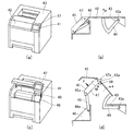
例えば特許文献1に開示された画像形成装置には図8(a)に示すように、画像形成装置内を開放する上カバー部材201、正面カバー部材202、上カバー部材201に取り付けられ画像形成装置の外側に向かって表示を行う表示パネル210が設けられている。この画像形成装置は、図8(b)に示すように、上カバー部材201が画像形成装置内を開放した状態において、表示パネル210の表示方向が略維持されるように構成されている。これは、図8(c)に示すように、上カバー部材201が回転軸221を中心として開閉する動作に連動して、上カバー部材201に取り付けられている表示パネル210が、回転軸223を中心に回転することによるものである。具体的には、特許文献1の画像形成装置では、液晶表示部は画像形成装置内部を開放した際に操作者の正面を向いた状態で、操作者への指示事項を表示しつつ、カバーは開放時には液晶表示部と異なる姿勢をとり、画像形成装置の前面を開放する姿勢をとる。このことで、操作者に対して、十分な作業スペースを与えることができる。また、特許文献1には、操作者の動作回数を減らすために、次のような機構を設けることが記載されている。それは、開閉部材が、液晶表示部を含む上カバー部材201と、液晶表示部を含まない正面カバー部材202との2つの部材から成り、これらのどちらか一方の部材を開閉動作した際に、他方が連動して開閉動作をするような機構である。
For example, as shown in FIG. 8A, the image forming apparatus disclosed in Patent Document 1 is attached to the
近年、タッチパネル式の表示部(操作部)が主流になっており、開閉部材の状態(開状態、閉状態)によらず、操作者が満足して操作できる表示部の剛性が求められている。
本発明は上記事情に鑑みてなされたものであり、操作部を有する可動部材が、開閉部材の開放動作に連動して移動し開閉部材とともに装置本体内を開放可能な画像形成装置において、操作部を押して操作する際の操作部の剛性を保つことを目的とする。
In recent years, touch panel type display units (operation units) have become mainstream, and the rigidity of the display units that can be operated satisfactorily by the operator regardless of the state of the opening / closing member (open state, closed state) is required. .
The present invention has been made in view of the above circumstances. In an image forming apparatus in which a movable member having an operation unit moves in conjunction with an opening operation of the opening / closing member and can open the inside of the apparatus body together with the opening / closing member. The purpose is to maintain the rigidity of the operation part when operating by pressing.
上記目的を達成するために本発明にあっては、
画像形成装置の装置本体に対して移動可能に設けられ、装置本体内を開閉する開閉部材と、
情報の入力操作が行われる操作部を有し、前記開閉部材に対して移動可能に連結された可動部材と、
を備え、
前記可動部材が、前記開閉部材の開放動作に連動して移動し前記開閉部材とともに前記装置本体内を開放可能に構成された画像形成装置において、
前記可動部材は、突当部を備え、前記開閉部材は、被突当部を備え、
前記突当部及び前記被突当部は、前記開閉部材を閉じた状態から開放していくと、互いに突き当たることで、前記可動部材が前記開閉部材に対してそれ以上移動することを規制することを特徴とする。
上記目的を達成するために本発明にあっては、
画像形成装置の装置本体に対して移動可能に設けられ、装置本体内を開閉する開閉部材と、
情報の入力操作が行われる操作部を有し、前記開閉部材に対して移動可能に連結された可動部材と、
を備え、
前記可動部材が、前記開閉部材の開放動作に連動して移動し前記開閉部材とともに前記装置本体内を開放可能に構成された画像形成装置において、
前記可動部材は、被突当部を備え、前記開閉部材は、突当部を備え、
前記突当部及び前記被突当部は、前記開閉部材を閉じた状態から開放していくと、互いに突き当たることで、前記可動部材が前記開閉部材に対してそれ以上移動することを規制することを特徴とする。
In order to achieve the above object, the present invention provides:
An opening / closing member provided movably with respect to the apparatus main body of the image forming apparatus, for opening and closing the inside of the apparatus main body;
A movable member having an operation unit for performing an input operation of information and movably connected to the opening and closing member;
With
In the image forming apparatus configured such that the movable member moves in conjunction with the opening operation of the opening and closing member and can open the inside of the apparatus main body together with the opening and closing member.
The movable member includes an abutting portion, and the opening and closing member includes an abutted portion.
The abutting portion and the object abutting part, when going to open from the closed state the closing member, by impinging one another, you regulating said movable member is moved more to the opening and closing member and wherein a call.
In order to achieve the above object, the present invention provides:
An opening / closing member provided movably with respect to the apparatus main body of the image forming apparatus, for opening and closing the inside of the apparatus main body;
A movable member having an operation unit for performing an input operation of information and movably connected to the opening and closing member;
With
In the image forming apparatus configured such that the movable member moves in conjunction with the opening operation of the opening and closing member and can open the inside of the apparatus main body together with the opening and closing member.
The movable member includes an abutted portion, and the opening and closing member includes an abutting portion.
The abutting part and the abutted part restrict the further movement of the movable member relative to the opening / closing member by abutting each other when the opening / closing member is released from the closed state. It is characterized by.
本発明によれば、操作部を有する可動部材が、開閉部材の開放動作に連動して移動し開閉部材とともに装置本体内を開放可能な画像形成装置において、操作部を押して操作する際の操作部の剛性を保つことが可能となる。 According to the present invention, in the image forming apparatus in which the movable member having the operation unit moves in conjunction with the opening operation of the opening / closing member and can open the inside of the apparatus main body together with the opening / closing member, the operation unit for operating by pressing the operation unit It becomes possible to maintain the rigidity of the.
以下に図面を参照して、この発明を実施するための形態を例示的に詳しく説明する。ただし、この実施の形態に記載されている構成部品の寸法、材質、形状それらの相対配置などは、発明が適用される装置の構成や各種条件により適宜変更されるべきものであり、この発明の範囲を以下の実施の形態に限定する趣旨のものではない。
また、以下に示す各実施例の構成は可能な限り組み合わることができる。
DETAILED DESCRIPTION Exemplary embodiments for carrying out the present invention will be described in detail below with reference to the drawings. However, the dimensions, materials, shapes, and relative arrangements of the components described in this embodiment should be appropriately changed according to the configuration of the apparatus to which the invention is applied and various conditions. It is not intended to limit the scope to the following embodiments.
Moreover, the structure of each Example shown below can be combined as much as possible.
[実施例1]
以下に、実施例1について説明する。
(画像形成装置の全体構成)
図7は、本実施例の画像形成装置の概略構成を示す断面図である。
図7を用いて、本実施例の画像形成装置100の画像形成動作について説明する。
まず、レーザダイオード、ポリゴンミラー、レンズ、反射ミラーを備えた露光装置115により、外部デバイス(不図示)から得られた画像情報に応じたレーザ光が、ドラム形状の電子写真感光体(以下、感光ドラム)108に照射される。これによって、感光ドラム108に画像情報に応じた潜像(静電潜像)が形成される。この潜像は、プロセスカートリッジ106の内部に構成される現像手段によって現像される。
[Example 1]
Example 1 will be described below.
(Overall configuration of image forming apparatus)
FIG. 7 is a cross-sectional view illustrating a schematic configuration of the image forming apparatus according to the present exemplary embodiment.
The image forming operation of the
First, an
画像形成装置100下方の給送トレイ118には記録媒体(記録材)であるシートSが積載されており、給送ローラ105により送り出されたシートSが分離部102で一枚毎に分離され、搬送ガイド部材116に沿って搬送される。給送トレイ118内のシートSは分離部102の下流に配置された搬送ローラ対103に送られ、さらにその下流に配置されたレジストローラ対104に搬送されて、ここでスキューの矯正が行われる。次いで、シートSは、感光ドラム108上の潜像が、感光ドラム108と転写ローラ107との間の転写ニップ部(転写位置)に到達するタイミングに合わせて、レジストローラ対104により転写ニップ部に搬送される。
Sheets S that are recording media (recording materials) are stacked on a
転写ニップ部には、転写手段としての転写ローラ107が配置されており、転写ローラ107に電圧が印加されることによって、感光ドラム108上のトナー像がシートSに転写される。
この後、トナー像が転写されたシートSは、搬送ガイド部材116に沿って定着装置117に搬送される。定着装置117では、シートS上に転写されたトナー像を、シートSに定着させるための定着処理が行われる。定着装置117は、加圧ローラ109、及び、ヒータを内蔵した定着ローラ110を備え、通過するシートSに熱及び圧力を印加して転写されたトナー像をシートS上に定着する。
A
Thereafter, the sheet S on which the toner image is transferred is conveyed to the
本実施例の画像形成装置100は、シートSへの両面印字を行う両面プリントモードと片面プリントモードを実行可能に設けられている。片面プリントモードの場合、定着処理後のシートSは、搬送ローラ対111,112により排出ローラ対113まで搬送され、排出ローラ対113により機外の排出トレイ114上に排出される。
後述する表示パネル41は、次に示す表示部と、操作者がオペレーションを行う為の入力キー部を備えた表示・操作パネル部である。表示部は、所要の操作を行い得る情報を表示するためのものであって、トナー補充、ジャム(紙詰まり)したシートSの除去等の装置の操作方法を操作者(ユーザ、作業者)に指示するためのものである。ここで、表示パネル41は、情報の入力操作が行われる操作部に相当する。
図1に示すように本実施例においては、製品を小型化するために、画像形成装置本体(以下、装置本体)101の外形(外装)から表示パネル41が突出しないように配置している。
The
A
As shown in FIG. 1, in the present embodiment, in order to reduce the size of the product, the
(開閉カバーと表示パネルの構成)
以下に、図1を用いて本実施例の画像形成装置100において、開閉カバーとしての第
1カバー42の開閉動作に連動して動作する各部材の構成について説明する。
図1(a)は、第1カバー42が閉じられた位置(閉位置)をとる状態(以下、閉状態)を示す概略斜視図である。図1(c)は、第1カバー42が開ききった位置(開位置)をとる状態(全開状態、以下、開状態)を示す概略斜視図である。図1(b),(d)はそれぞれ図1(a),(c)に示す画像形成装置100において表示パネル41を正面(前面)としたときの右側面方向から表示パネル41と第1カバー42を見た概略図である。
第1カバー42は、プロセスカートリッジ106の交換、及びジャム処理の際に開閉される。ここで、第1カバー42は、装置本体101に対して移動可能に設けられ、装置本体内を開閉する開閉部材に相当する。
(Structure of opening / closing cover and display panel)
Hereinafter, the configuration of each member that operates in conjunction with the opening / closing operation of the
FIG. 1A is a schematic perspective view showing a state where the
The
本実施例の表示パネル41は、第2のリンク部材47に一体に設けられ、第1カバー42の閉状態では、図1(a)に示すように、表示パネル41は第1カバー42に隣接するように配置されている。ここで、第2のリンク部材47は、可動部材に相当する。
本実施例においては、第2のリンク部材47が、第1カバー42の開閉動作に連動して移動可能に第1カバー42に連結されている。そして、第2のリンク部材47が第1カバー42の開放動作に連動して移動し第1カバー42とともに装置本体101内を開放可能に構成されている。
The
In the present embodiment, the
このことで、操作者が第1カバー42を開くと、表示パネル41が配設された第2のリンク部材47が第1カバー42の開放動作に連動して移動し、第1カバー42及び第2のリンク部材47はそれぞれ図1(c)に示す開状態となる。これにより、画像形成装置100の装置本体101内を開放する開口部が形成され、プロセスカートリッジ106の交換作業等が可能となる。
このとき、表示パネル41は、操作者が正面から見やすい姿勢(角度)を略維持したまま、図1(c)に示す第1カバー42及び第2のリンク部材47が開状態となる位置へ移動するように構成されている。
Thus, when the operator opens the
At this time, the
これは、第1カバー42及び第2のリンク部材47を含む複数のリンク部材が回転可能に連結されリンク機構を構成することで、第2のリンク部材47が装置本体101に移動可能に連結されていることによる。本実施例では、第2のリンク部材47は、第1カバー42の移動動作に連動して、表示パネル41が向いている方向が所定の方向(装置本体101の外側を向く方向)に維持されるように第1カバー42に対する姿勢を変化させながら移動する。
以下、この点について、より詳細に説明する。なお、第1カバー42が開放されると第2のリンク部材47も開放されるため、以下の説明では、第1カバー42及び第2のリンク部材47が開状態にあることを単に第1カバー42が開状態という場合もある。
This is because a plurality of link members including the
Hereinafter, this point will be described in more detail. Since the
本実施例においては、装置本体101、第1カバー42、第2のリンク部材47、及び、第1のリンク部材45により、4節リンク機構が構成されている。ここで、第1のリンク部材45は連結部材に相当する。
すなわち図1(d)に示すように、装置本体101に対して第1カバー42及び第1のリンク部材45がそれぞれ回転可能に連結支持(軸支)され、第1カバー42及び第1のリンク部材45それぞれに対して第2のリンク部材47が回転可能に連結支持されている。
ここで、本実施例では図1(d)に示すように、第1カバー42には、アーム部材44が一体に設けられ、アーム部材44が、装置本体101に対して回転軸43aを回転中心として回転可能に連結支持されている。このことで、第1カバー42が装置本体101に対して回転可能に連結支持されている。そして、第1カバー42の開閉動作が行われる際には、アーム部材44が装置本体101に対して回転することとなる。
In the present embodiment, the apparatus
That is, as shown in FIG. 1D, the
Here, in this embodiment, as shown in FIG. 1D, the
また、第1のリンク部材45は、装置本体101に設けられたベース部材46に対して回転軸46aにより回転可能に連結支持されている。
そして、第2のリンク部材47は、一端側が回転軸47aにより第1カバー42に対して回転可能に連結支持され、他端側が回転軸45aにより第1のリンク部材45に対して回転可能に連結支持されている。リンク機構を構成する2つのリンク部材を連結する方法としては、一方のリンク部材に回転軸を設け、他方のリンク部材に軸受を設けることで、回転軸と軸受を連結させる方法を例示できる。このとき、回転軸は、一方のリンク部材に一体に設けてもよいし、別体として設けてもよい。
Further, the
The
第1カバー42は、開放される際、回転軸43aを回転中心として図1(b)において矢印a方向(時計回り方向)へ回転する。第1カバー42が回転すると、第1カバー42の移動に連動して第2のリンク部材47及び第1のリンク部材45が移動する。このとき、第2のリンク部材47は、回転軸47aを回転中心として第1カバー42に対して回転するとともに、回転軸45aを回転中心として第1のリンク部材45に対して回転する。また、第1のリンク部材45は、回転軸45aを回転中心として第2のリンク部材47に対して回転するとともに、回転軸46aを回転中心としてベース部材46(装置本体101)に対して回転する。このようにして、第1カバー42は、図1(d)に示す開状態となるまで、図1(d)の矢印a方向に回転する。
When the
このようなリンク機構により、表示パネル41は、第1カバー42の開状態においても、操作者にとって見やすい姿勢(角度)を維持することが出来る。
ここで、図1に示す第2カバー43は装置本体101の天面カバーを構成している。
With such a link mechanism, the
Here, the
以下に、本実施例の特徴的な構成について説明する。
本実施例においては、第2のリンク部材47に突当部としての突起部48が形成されていることを特徴とする。
本実施例においては、図1(a),(c)に示すように、第2のリンク部材47は回転軸方向に第1カバー42と並んで配置されており、突起部48は、第1カバー42に向かって回転軸方向に突出するように形成されている。この突起部48は、第1カバー42の閉状態では、図1(b)に示すように、第1カバー42に当接していない。
Hereinafter, a characteristic configuration of the present embodiment will be described.
In the present embodiment, the
In the present embodiment, as shown in FIGS. 1A and 1C, the
突起部48は、第1カバー42を閉じた状態から開放していくと、第1カバー42が図1(d)に示す矢印a方向に回転して、第1カバー42の被突当部42aに突き当たる(当接する)ように形成されている。このとき、突起部48が被突当部42aに突き当たることで、第2のリンク部材47が第1カバー42に対してそれ以上移動することが規制(制限、阻止)される。
このように、突起部48及び被突当部42aが互いに突き当たることで、第1カバー42及び第2のリンク部材47が開状態となる。
When the
Thus, the
ここで、図8に示すような従来の形態では、上カバー部材201が開状態(図8(b))で、操作者が、表示パネル210に対して力Fを与えた時、表示パネル210には回転軸224を中心としたモーメントMが働く(図8(c))。この力によって、表示パネル210は上カバー部材201に対して傾くことが懸念される。また、傾くことで操作者が表示パネル210を操作し難い状況となることが懸念される。
Here, in the conventional form as shown in FIG. 8, when the operator applies a force F to the
これに対して、本実施例においても、第1カバー42が開状態のときに、操作者により力Fで表示パネル41が押される(入力操作が行われる)と、回転軸47aを中心としたモーメントMが働く(図1(d))。このとき、本実施例においては、第2のリンク部材47の突起部48と第1カバー42の被突当部42aが突き当たった状態にあり、この状
態で表示パネル41が押されると、突起部48と被突当部42aが互いに突き当たる方向に力がかかることとなる。このため、突起部48と被突当部42aが突き当たることで生じる反力により、モーメントMは相殺されることとなる。
On the other hand, also in the present embodiment, when the
このように、第1カバー42が開状態において、操作者が表示パネル41を押して操作した場合、表示パネル41(第2のリンク部材47)に働くモーメントMは上記反力により相殺される。このため、表示パネル41が傾いたり、変形したりせずに剛性を保つことが出来る。
In this way, when the operator pushes the
以上説明したように、本実施例では、表示パネル41を開閉カバー(第1カバー42)に連動して移動可能に具備する画像形成装置において、次のような構成としている。
すなわち、第1カバー42の開状態では、突起部48及び被突当部42aが互いに突き当たることで、第2のリンク部材47が第1カバー42に対してそれ以上開放される方向に移動することが規制されている。
これにより、第1カバー42の開状態においては、第2のリンク部材47が第1カバー42に当接状態となるので、第2のリンク部材47の剛性を向上させることが可能となる。したがって、第1カバー42の開状態で、操作者が表示パネル41を押して操作した場合であっても、表示パネル41が傾いたり、変形したりせずに剛性を保つことが可能となる。
As described above, in this embodiment, the image forming apparatus that includes the
That is, in the open state of the
Thereby, in the open state of the
ここで、本実施例においては、第2のリンク部材47に突起部48が設けられ、第1カバー42に被突当部42aが設けられた形態について説明したが、これに限るものではない。第1カバー42に突起部(突当部)が設けられ、第2のリンク部材47に被突当部が設けられるものであってもよい。また、突当部及び被突当部の形状やその位置においても特に限定されるものではない。互いに突き当たることで、第2のリンク部材47が第1カバー42に対してそれ以上開放される方向に移動することを規制する部分(領域)が第1カバー42と第2のリンク部材47との間に設けられていればよい。
また、表示パネル41は、表示部と、入力キー部を備えた構成であったが、これに限るものではない。すなわち、表示パネル41には、表示する機能が備えられていなくてもよく、操作者が情報の入力操作を行うための操作部が設けられているものであればよい。第1カバー42の開状態において、第2のリンク部材47に対して、さらに開放する方向(図1(d)のF方向)に力がかかる場合であれば、本発明を好適に適用することができる。
Here, in the present embodiment, the description has been given of the form in which the
The
また、本実施例では、第1カバー42及び第2のリンク部材47が4節リンク機構を構成する形態について説明したが、これに限るものではない。すなわち、第1カバー42及び第2のリンク部材47を含む複数のリンク部材が回転可能に連結されリンク機構を構成し、第1カバー42及び第2のリンク部材47が装置本体101に対して移動可能な形態であっても、本発明を好適に適用することができる。
また、本実施例では、表示パネル41が向いている方向が所定の方向に維持されるように第1カバー42に対する姿勢を変化させながら移動する形態について説明したが、これに限るものではない。本実施例では、第1カバー42の開状態において、第2のリンク部材47及び表示パネル41の剛性を向上できるもので、このとき、表示パネル41が向いている方向が特に限定されるものではない。
In the present embodiment, the form in which the
Further, in the present embodiment, the mode of moving while changing the posture with respect to the
[実施例2]
以下に、実施例2について説明する。なお、本実施例においては、実施例1に対して異なる構成部分について述べることとし、実施例1と同様の構成部分については、その説明を省略する。
本実施例では、実使用上における表示パネル41の剛性を実施例1の形態よりもさらに
強くしている。
図2は、本実施例の画像形成装置100の要部を示す概略図である。
[Example 2]
Example 2 will be described below. In the present embodiment, the different components from the first embodiment will be described, and the description of the same components as those in the first embodiment will be omitted.
In the present embodiment, the rigidity of the
FIG. 2 is a schematic diagram illustrating a main part of the
実施例1においては、図1(d)に示す力Fが表示パネル41上の上側に強く作用した場合、アーム部材44に伝わる力が大きくなり、第2カバー43と突き当たるまでアーム部材44が撓んでしまうことが懸念される。また、力Fが表示パネル41上の下側に強く作用した場合、第1のリンク部材45に伝わる力が大きくなり、ベース部材46と突き当たるまで第1のリンク部材45が撓んでしまうことが懸念される。
アーム部材44や第1のリンク部材45が撓んでしまうことにより装置本体101側との間でガタツキが生じてしまうことが懸念される。
これを改善するために、本実施例では、第1カバー42の開状態で、アーム部材44に当接する(突き当たる)当接部49aと、第1のリンク部材45に当接する当接部49bが、装置本体101にそれぞれ配設されている。
In the first embodiment, when the force F shown in FIG. 1D strongly acts on the upper side of the
There is a concern that the
In order to improve this, in this embodiment, when the
図2に示すように、第1カバー42が開放される際、第1カバー42は回転軸43aを回転中心として、第1カバー42の被突当部42aが第2のリンク部材47の突起部48と当接するまで矢印a方向に回転する。
そして、第1カバー42の被突当部42aと第2のリンク部材47の突起部48が当接し、第1カバー42が開状態となるとき、アーム部材44が当接部49aに当接し、第1のリンク部材45が当接部49bに当接する。ここで、アーム部材44のうち当接部49aと当接する部分が当接部として機能し、この当接部と当接部49aが、互いに当接する第1当接部に相当する。また、第1のリンク部材45のうち当接部49bと当接する部分が当接部として機能し、この当接部と当接部49bが、互いに当接する第2当接部に相当する。この第1当接部においては、2つの部材間で互いに当接するように構成されるものであればよく、各部材に設けられる当接部の形状は限定されるものではない。第2当接部においても同様である。
As shown in FIG. 2, when the
Then, when the abutted
このような構成により、第1カバー42が開状態において、表示パネル41、第2のリンク部材47、突起部48、第1カバー42、アーム部材44、第1のリンク部材45、第2カバー43(装置本体101)は一体となる。
これにより、本実施例では、第1カバー42の開状態における、表示パネル41の剛性を実施例1の構成より強く保つことができる。
これにより、第1カバー42が開状態において操作者により表示パネル41が押されるときに懸念された、アーム部材44、及び、第1のリンク部材45のガタつきの発生を防止することができる。
With such a configuration, when the
Thereby, in the present embodiment, the rigidity of the
Accordingly, it is possible to prevent the
[実施例3]
以下、実施例3について説明する。なお、本実施例においては、実施例1,2に対して異なる構成部分について述べることとし、実施例1,2と同様の構成部分については、その説明を省略する。
本実施例では、第1カバー42の開状態で互いに嵌合する嵌合部が第2のリンク部材47と第1カバー42の間に設けられ、第1カバー42の閉状態で互いに嵌合する嵌合部が、第2のリンク部材47と装置本体101の間に設けられている。
[Example 3]
Example 3 will be described below. In the present embodiment, different components from those of the first and second embodiments will be described, and the description of the same components as those of the first and second embodiments will be omitted.
In the present embodiment, a fitting portion that fits in the open state of the
図3(a)は、本実施例の画像形成装置100を示す概略斜視図である。図3(b)は、図3(a)における矢印BVの方向から画像形成装置100の要部を見たときの概略斜視図である。図3(b)においては、説明の便宜上、表示パネル41を図示していない。図3(c),(d)は、図3(a)におけるA−A断面を示す概略断面図であり、それぞれ全開状態、閉状態を示している。
FIG. 3A is a schematic perspective view showing the
本実施例では、図3(a),(b)に示すように、第1カバー42に第1の溝53が設けられ、装置本体101のインナーカバー50に第2の溝54が設けられている。そして、図3(c),(d)に示すように、第2のリンク部材47は、第1の溝53に嵌合可能に設けられた第1の突起部51と、第2の溝54に嵌合可能に設けられた第2の突起部52とを備えている。
ここで、第1の突起部51は突当部に相当し、第1の溝53は被突当部に相当する。また、第2の突起部52と第2の溝54は、相互嵌合部に相当する。各嵌合部においては、2つの部材間で互いに嵌合するように構成されるものであればよく、各部材に設けられる嵌合部の形状は限定されるものではない。例えば、本実施例では、第1カバー42に第1の溝53が設けられ、第2のリンク部材47に第1の突起部51が設けられているが、第1カバー42に突起が設けられ、第2のリンク部材47に溝が設けられるものであってもよい。
In the present embodiment, as shown in FIGS. 3A and 3B, the
Here, the
図3(c)に示すように、第1カバー42が開放される際、第1カバー42は、回転軸43aを回転中心として、第2のリンク部材47に設けられた第1の突起部51が第1カバー42と当接するまで矢印方向aへ回転する。
そして、第2のリンク部材47の第1の突起部51と、第1カバー42の第1の溝53とが嵌合する。このとき、第1カバー42及び第2のリンク部材47が開状態となる。このような構成により、第1カバー42に対する第2のリンク部材47の位置決めを行うことができる。本実施例では、この嵌合部を溝と突起で構成し、溝(突起)が、第2のリンク部材47の回転軸方向に交差する方向に延びるように構成している。
このことで、第1カバー42の開状態において、第1カバー42に対する第2のリンク部材47の回転軸方向の位置決めをより確実に行うことができる。
これにより、第1カバー42が開状態のときに、操作者が表示パネル41を操作したときの回転軸方向に対する表示パネル41の剛性をより向上させることができ、第1カバー42に対して第2のリンク部材47が回転軸方向にガタついてしまうようなことはない。
As shown in FIG. 3C, when the
Then, the
Thus, in the opened state of the
Thereby, when the
また、第1カバー42の閉じ動作に伴い、第2のリンク部材47の第1の突起部51と第1カバー42の第1の溝53との嵌合状態が解除される。そして、第1カバー42の閉状態では、第2のリンク部材47の第2の突起部52とインナーカバー50の第2の溝54とが嵌合するようになる。本実施例では、この嵌合部においても溝と突起で構成し、溝(突起)が、第2のリンク部材47の回転軸方向に交差する方向に延びるように構成している。
Further, with the closing operation of the
このことで、第1カバー42の閉状態においても、第1カバー42及びインナーカバー50(装置本体101)に対する第2のリンク部材47の回転軸方向の位置決めをより確実に行うことができる。これにより、第1カバー42が閉状態のときに、操作者が表示パネル41を操作したときの回転軸方向に対する表示パネル41の剛性をより向上させることができる。
ここで、本実施例の構成に加えてさらに、実施例2の当接部49a,49bに相当する部材が配設されるものであってもよい。
Thereby, even in the closed state of the
Here, in addition to the configuration of the present embodiment, members corresponding to the
[実施例4]
以下に、実施例4について説明する。なお、本実施例においては、実施例1〜3に対して異なる構成部分について述べることとし、実施例1〜3と同様の構成部分については、その説明を省略する。
本実施例では、装置本体101の側面(側壁)としてのサイド部材40で、リンク機構の回転軸45a,47aを軸支する構成としている。
[Example 4]
Example 4 will be described below. In the present embodiment, different components from those of the first to third embodiments will be described, and the description of the same components as those of the first to third embodiments will be omitted.
In this embodiment, the
図4(a)は、本実施例の画像形成装置100を示す概略斜視図、図4(b)は、第1
カバー42が開状態のときの画像形成装置100の要部を示す概略断面図である。
本実施例においては、画像形成装置100の外装部分が、第1カバー42、表示パネル41が設けられた第2のリンク部材47、及びサイド部材40を含んで構成されている。そして、第1のリンク部材45と第2のリンク部材47の連結部である回転軸45a、及び、第2のリンク部材47と第1カバー42の連結部である回転軸47aが、サイド部材40に軸支されている。
FIG. 4A is a schematic perspective view showing the
2 is a schematic cross-sectional view showing a main part of
In the present embodiment, the exterior portion of the
図4(b)に示すように、サイド部材40には、第1カバー42の開閉動作に連動して移動する回転軸47a,45aの軌跡(移動軌跡)に沿って、切欠き(溝)40a,40bが設けられている。本実施例では、第1カバー42の開閉動作の過程で常に、回転軸47a,45aが切欠き40a,40bに軸支(ガイド、案内)されるように構成されている。
さらに、切欠き40a,40bの端部にはそれぞれ、第1カバー42が開状態のときに、回転軸47a,45aが当接する当接部55a,55bが設けられている。ここで、回転軸47a,45aは突当部に相当し、サイド部材40の当接部55a,55bは各突当部に対応する被突当部に相当する。また、切欠き40a,40bはガイド部に相当する。また、第1のリンク部材45は、複数のリンク部材のうちの1つの部材に相当する。
As shown in FIG. 4B, the
Furthermore,
図4(b)に示すように、第1カバー42が開放される際、第1カバー42は回転軸43aを回転中心として矢印a方向に回転する。そして、回転軸47aが切欠き40aにガイドされた後、当接部55aと当接することで、第1カバー42が開状態となる。
そして、第1カバー42が開状態のときに、操作者により力Fで表示パネル41が押されると、回転軸47aを中心としたモーメントMが働く。このとき、本実施例においては、回転軸47aが当接部55aと当接した状態にあるため、回転軸47aと当接部55aが当接することで生じる反力により、モーメントMは相殺されることとなる。
As shown in FIG. 4B, when the
When the
このように、本実施例においても、第1カバー42の開状態において、操作者が表示パネル41を押して操作した場合、表示パネル41に働くモーメントMは上記反力により相殺される。このため、表示パネル41が傾いたり、変形したりせずに剛性を保つことが出来る。
したがって、本実施例においても実施例1同様、第1カバー42の開状態においては、第2のリンク部材47の剛性が向上した状態となっている。したがって、第1カバー42の開状態で、操作者が表示パネル41を押して操作した場合であっても、表示パネル41が傾いたり、変形したりせずに剛性を保つことが可能となる。
Thus, also in the present embodiment, when the operator pushes the
Therefore, also in the present embodiment, as in the first embodiment, the rigidity of the
さらに、本実施例では、第1カバー42が開放される際、回転軸45aにおいても切欠き40bにガイドされ、第1カバー42の開状態では当接部55bと当接している。
これにより、第1カバー42の開状態において、第2のリンク部材47の剛性をより向上させることができ、第1のリンク部材45に生じることが懸念されるガタつきも抑制することができる。したがって、第1カバー42の開状態において、表示パネル41(第2のリンク部材47)の剛性を実施例1よりも強く保つことができる。
Further, in the present embodiment, when the
Thereby, in the open state of the
ここで、本実施例においては、第1カバー42の開閉動作の過程で常に、回転軸47a,45aが切欠き40a,40bに軸支されるものであったが、これに限るものではない。回転軸47a,45aが当接部55a,55bに当接することで、第1カバー42が開状態となるものであればよく、第1カバー42の開閉動作の過程で回転軸47a,45aが切欠き40a,40bに軸支されない構成であってもよい。
また、本実施例では、突当部として回転軸47aを適用しているが、これに限るものではなく、突当部は回転軸47a(第1カバー42に対する第2のリンク部材47の回転中心)と同軸上に配設された部材であればよい。また、突当部は、サイド部材40の当接部
55aに当接することで、第1カバー42が開状態となるものであればよく、回転軸47aと同軸上に配設されるものでなくてもよい。
また、本実施例の構成に加えてさらに、実施例1〜3で説明した構成を適宜適用してもよい。例えば、本実施例の構成において、さらに、実施例1の突起部48及び被突当部42aに相当する部材が配設されるものであってもよく、実施例2の当接部49a,49bに相当する部材が配設されるものであってもよい。また、当接部55a,55bが回転軸47a,45aを嵌合可能に構成されるものであってもよい。
Here, in the present embodiment, the
In this embodiment, the
In addition to the configuration of the present embodiment, the configurations described in Embodiments 1 to 3 may be applied as appropriate. For example, in the configuration of the present embodiment, members corresponding to the
[実施例5]
以下に、実施例5について説明する。なお、本実施例においては、実施例1に対して異なる構成部分について述べることとし、実施例1と同様の構成部分については、その説明を省略する。
まず、本実施例の課題について詳細に説明する。
図6は、本実施例の課題について説明するための概略図である。図6(a1)は第1カバー42の開状態を示す概略図であり、図6(a2)は、図6(a1)において四角Cで囲まれた領域の拡大図である。図6(b1),(c1)は、画像形成装置の正面部を示す概略斜視図であり、図6(b2),(c2)はそれぞれ図6(b1),(c1)において四角D,Eで囲まれた領域の拡大図である。
[Example 5]
Example 5 will be described below. In the present embodiment, the different components from the first embodiment will be described, and the description of the same components as those in the first embodiment will be omitted.
First, the problem of the present embodiment will be described in detail.
FIG. 6 is a schematic diagram for explaining the problem of the present embodiment. FIG. 6A1 is a schematic view showing an open state of the
図6(a1),(a2)に示すように、第1のリンク部材45と第2のリンク部材47の連結部が常に嵌合状態となっている場合を想定する。このとき、第1カバー42が閉状態にある場合には、第1カバー42の当接部(突き当て部)42eと、第2のリンク部材47の当接部47eは、装置本体101の正面(前面)に配設された前カバー55に当接することで位置決めされる。
ここで、第1のリンク部材45において、回転軸45aから回転軸46aまでの距離が部品の公差分だけ短い場合には、当接部42eは当接部47eより先に前カバー55に当接することになる。このため、第1カバー42は所定の(本来の)位置まで閉鎖することができず、第1カバー42と第2のリンク部材47との間に段差が生じてしまうことが懸念される(図6(b1),(b2))。
As shown in FIGS. 6A1 and 6A2, it is assumed that the connecting portion between the
Here, in the
一方、第1のリンク部材45において、回転軸45aから回転軸46aまでの距離が部品の公差分だけ長い場合には、当接部47eは当接部42eより先に前カバー55に当接することになる。このため、第2のリンク部材47は所定の位置まで閉鎖することができず、第1カバー42と第2のリンク部材47との間に段差が生じてしまうことが懸念される(図6(c1),(c2))。
そして、第1カバー42と第2のリンク部材47との間に段差が生じることで、表示パネル41が宙に浮いてしまい、表示パネル41を操作する際の剛性が下がることが懸念される。
ここで、第1カバー42の開状態においては、操作者が表示パネル41を押して操作した場合に、表示パネル41が第1カバー42に対して傾いたり、変位したりせずに剛性を保つことができる。
On the other hand, in the
In addition, there is a concern that a step is generated between the
Here, in the open state of the
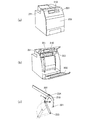
図5は、本実施例の画像形成装置の要部を示す概略図である。
図5(a)は、第1カバー42の閉状態を実線で示し、開状態態を点線で示している。図5(b),(c)はそれぞれ図5(a)の四角A,Bで囲まれた部分の拡大図を示している。
本実施例の特徴として、第1のリンク部材45と第2のリンク部材47との連結部は、第1のリンク部材45の回転軸45aと、第2のリンク部材47の嵌合穴(孔)47bとが遊嵌するように構成されている。そして、第1のリンク部材45の回転軸45aと、第2のリンク部材47の嵌合穴47bとが、第1カバー42の開閉動作に伴って回転軸45
aと嵌合穴47bとが相対回転するように構成されている。
FIG. 5 is a schematic diagram illustrating a main part of the image forming apparatus according to the present exemplary embodiment.
FIG. 5A shows a closed state of the
As a feature of the present embodiment, the connecting portion between the
a and the
また、図5(b),(c)に示すように、嵌合穴47bにおいて、回転軸45aを挟んで互いに対向する所定の部分を、一対の対向部47dとする。
このとき、回転軸45aの回転軸心に垂直な方向のうち一対の対向部47dの対向方向dにおける一対の対向部間の間隔bと、一対の対向部間の回転軸45aの幅cとの寸法差が、次のようになるように構成されている。すなわち、間隔bと幅cとの寸法差が、第1カバー42の閉状態のときよりも開状態のときの方が小さくなるように構成されている。本実施例においては、第1カバー42の開状態のときには、間隔bと幅cとの寸法差はなく、回転軸45aが嵌合穴47bの一対の対向部47d間に嵌まるように構成されている。
これは、対向方向dにおける回転軸45aの幅が、第1カバー42の閉状態のときよりも開状態のときの方が大きくなるように構成されていることによる。ここで、回転軸45aは回転部材に相当し、嵌合穴47bは遊嵌部に相当する。
Further, as shown in FIGS. 5B and 5C, in the
At this time, the distance b between the pair of facing portions in the facing direction d of the pair of facing
This is because the width of the
このような構成により、図5(b)に示すように、第1カバー42の閉状態においては、第1のリンク部材45の回転軸45aの軸外周部45bと、第2のリンク部材47の嵌合穴(孔)47bの穴内周面47cとの間には、隙間が生じることとなる。
これにより、第1カバー42の閉状態では、第2のリンク部材47は、回転軸45aとの間に生じた隙間分だけ動作(移動)できるため、第1カバー42と第2のリンク部材47は所定の位置まで閉鎖することができる。
その結果、図6で説明したような、第1カバー42と第2のリンク部材47との間に段差が生じるようなことはなくなる。
したがって、第1カバー42の閉状態において、操作者が表示パネル41を押して操作した場合に、表示パネル41が第1カバー42(装置本体101)に対して傾いたり、変位したりせずに剛性を保つことができ、外観上の問題も生じなくなる。
With such a configuration, as shown in FIG. 5B, in the closed state of the
Thereby, in the closed state of the
As a result, a step is not generated between the
Therefore, when the operator presses the
一方、第1カバー42の開状態では、図5(c)に示すように、回転軸45aが嵌合穴47bの一対の対向部47d間に嵌まるように構成されていることで、軸外周部45bと穴内周面47cとの間には隙間が無い状態となっている。
その結果、第1カバー42の開状態では、第1カバー42と第2のリンク部材47とが確実に嵌合された状態となるため、第2のリンク部材47の剛性を向上させることが可能となる。したがって、第1カバー42の開状態で、操作者が表示パネル41を押して操作した場合に、表示パネル41が第1カバー42に対して傾いたり、変位したりせずに剛性を保つことができる。
On the other hand, in the open state of the
As a result, since the
ここで、本実施例では、第1のリンク部材45を穴形状とし、第2のリンク部材47を軸形状としているが、これに限るものではなく、第1のリンク部材45を軸形状とし、第2のリンク部材47を穴形状としても上記同様の効果を得ることができる。また、本実施例においては、第1カバー42の開状態のときには、間隔bと幅cとの寸法差はなくなるように構成しているが、これに限るものではない。間隔bと幅cとの寸法差が、第1カバー42の閉状態のときよりも開状態のときの方が小さくなるように構成されるものであれば、上記同様の効果を得ることができる。
また、本実施例では、回転軸45aにおける連結部の形状をカム形状としているが、これに限るものではなく、回転軸46aにおける連結部でカム形状を用いても同様の効果を得ることができる。すなわち、第1のリンク部材45の回転軸46aを穴(または軸)形状とし、ベース部材46の回転軸46aを軸(または穴)形状としても良い。
また、本実施例では、第1のリンク部材45の公差を考慮したため、第1のリンク部材45の連結部の形状を上記のような軸または穴形状とするものであった。このような形状は、他のリンク部材の公差を考慮した場合には、それぞれの連結部において適宜適用され
るものであるとよい。また本実施例においても4節リンク機構を構成する形態について説明したが、これに限るものではない。すなわち、第1カバー42及び第2のリンク部材47を含む複数のリンク部材が回転可能に連結されリンク機構を構成し、第1カバー42及び第2のリンク部材47が装置本体101に対して移動可能な形態であっても、本発明を好適に適用することができる。
Here, in the present embodiment, the
In this embodiment, the shape of the connecting portion on the
In this embodiment, since the tolerance of the
41…表示パネル、42…第1カバー、42a…被突当部、47…第2のリンク部材、48…突起部、100…画像形成装置、101…装置本体
DESCRIPTION OF
Claims (14)
情報の入力操作が行われる操作部を有し、前記開閉部材に対して移動可能に連結された可動部材と、
を備え、
前記可動部材が、前記開閉部材の開放動作に連動して移動し前記開閉部材とともに前記装置本体内を開放可能に構成された画像形成装置において、
前記可動部材は、突当部を備え、前記開閉部材は、被突当部を備え、
前記突当部及び前記被突当部は、前記開閉部材を閉じた状態から開放していくと、互いに突き当たることで、前記可動部材が前記開閉部材に対してそれ以上移動することを規制することを特徴とする画像形成装置。 An opening / closing member provided movably with respect to the apparatus main body of the image forming apparatus, for opening and closing the inside of the apparatus main body;
A movable member having an operation unit for performing an input operation of information and movably connected to the opening and closing member;
With
In the image forming apparatus configured such that the movable member moves in conjunction with the opening operation of the opening and closing member and can open the inside of the apparatus main body together with the opening and closing member.
The movable member includes an abutting portion, and the opening and closing member includes an abutted portion.
The abutting portion and the object abutting part, when going to open from the closed state the closing member, by impinging one another, you regulating said movable member is moved more to the opening and closing member an image forming apparatus comprising and this.
情報の入力操作が行われる操作部を有し、前記開閉部材に対して移動可能に連結された可動部材と、A movable member having an operation unit for performing an input operation of information and movably connected to the opening and closing member;
を備え、With
前記可動部材が、前記開閉部材の開放動作に連動して移動し前記開閉部材とともに前記装置本体内を開放可能に構成された画像形成装置において、In the image forming apparatus configured such that the movable member moves in conjunction with the opening operation of the opening and closing member and can open the inside of the apparatus main body together with the opening and closing member.
前記可動部材は、被突当部を備え、前記開閉部材は、突当部を備え、The movable member includes an abutted portion, and the opening and closing member includes an abutting portion.
前記突当部及び前記被突当部は、前記開閉部材を閉じた状態から開放していくと、互いに突き当たることで、前記可動部材が前記開閉部材に対してそれ以上移動することを規制することを特徴とする画像形成装置。The abutting part and the abutted part restrict the further movement of the movable member relative to the opening / closing member by abutting each other when the opening / closing member is released from the closed state. An image forming apparatus.
前記突当部は、前記被突当部に向かって前記回転軸方向に突出するように形成されていることを特徴とする請求項1又は2に記載の画像形成装置。 The movable member is pivotally supported on a rotation shaft so as to be rotatable with respect to the opening / closing member, and is arranged side by side with the opening / closing member in the rotation axis direction,
The abutting portion is an image forming apparatus according to claim 1 or 2, characterized in that said formed so as to protrude to the rotation axis direction toward a press-contact section.
前記装置本体と前記連結部材とには、前記突当部及び前記被突当部が互いに突き当たるときに、互いに当接する第2当接部が設けられていることを特徴とすることを特徴とする請求項1乃至5のいずれか1項に記載の画像形成装置。 A connecting member for movably connecting the movable member to the apparatus main body;
The apparatus main body and the connecting member are provided with a second abutting portion that abuts against each other when the abutting portion and the abutted portion abut each other. the image forming apparatus according to any one of claims 1 to 5.
前記開閉部材が前記装置本体内を開くと、前記カートリッジが前記装置本体の外部に露出することを特徴とする請求項1乃至13のいずれか1項に記載の画像形成装置。The image forming apparatus according to claim 1, wherein when the opening / closing member opens the inside of the apparatus main body, the cartridge is exposed to the outside of the apparatus main body.
Priority Applications (3)
| Application Number | Priority Date | Filing Date | Title |
|---|---|---|---|
| JP2014091362A JP6335615B2 (en) | 2014-04-25 | 2014-04-25 | Image forming apparatus |
| US14/695,882 US9690252B2 (en) | 2014-04-25 | 2015-04-24 | Image forming apparatus |
| CN201510205453.2A CN105005186B (en) | 2014-04-25 | 2015-04-27 | Imaging device |
Applications Claiming Priority (1)
| Application Number | Priority Date | Filing Date | Title |
|---|---|---|---|
| JP2014091362A JP6335615B2 (en) | 2014-04-25 | 2014-04-25 | Image forming apparatus |
Publications (3)
| Publication Number | Publication Date |
|---|---|
| JP2015210361A JP2015210361A (en) | 2015-11-24 |
| JP2015210361A5 JP2015210361A5 (en) | 2017-06-15 |
| JP6335615B2 true JP6335615B2 (en) | 2018-05-30 |
Family
ID=54334679
Family Applications (1)
| Application Number | Title | Priority Date | Filing Date |
|---|---|---|---|
| JP2014091362A Active JP6335615B2 (en) | 2014-04-25 | 2014-04-25 | Image forming apparatus |
Country Status (3)
| Country | Link |
|---|---|
| US (1) | US9690252B2 (en) |
| JP (1) | JP6335615B2 (en) |
| CN (1) | CN105005186B (en) |
Families Citing this family (13)
| Publication number | Priority date | Publication date | Assignee | Title |
|---|---|---|---|---|
| JP6116390B2 (en) * | 2013-06-13 | 2017-04-19 | キヤノン株式会社 | Opening / closing mechanism and image forming apparatus |
| JP2017044991A (en) * | 2015-08-28 | 2017-03-02 | 株式会社リコー | Image forming apparatus |
| JP6460005B2 (en) * | 2016-02-18 | 2019-01-30 | 京セラドキュメントソリューションズ株式会社 | Image forming apparatus |
| US10241464B2 (en) * | 2016-06-28 | 2019-03-26 | Fuji Xerox Co., Ltd. | Image forming apparatus having two opening and closing portions |
| JP6766494B2 (en) * | 2016-07-20 | 2020-10-14 | 株式会社リコー | Image forming device |
| JP6901342B2 (en) * | 2017-07-21 | 2021-07-14 | 東芝テック株式会社 | Information processing device |
| JP6999159B2 (en) * | 2017-09-28 | 2022-01-18 | 株式会社ナチュラレーザ・ワン | Operation panel support device and information terminal device |
| JP6955966B2 (en) * | 2017-11-01 | 2021-10-27 | 株式会社オカムラ | Goods loading / unloading device |
| JP7174613B2 (en) | 2018-12-11 | 2022-11-17 | セイコーインスツル株式会社 | Printers and display devices for printers |
| US20220201139A1 (en) * | 2019-05-05 | 2022-06-23 | Hewlett-Packard Development Company, L.P. | Telescopic mounts for imaging devices |
| US11409225B2 (en) | 2019-12-27 | 2022-08-09 | Canon Kabushiki Kaisha | Image forming apparatus with draw-out unit having electrically contactable contact pairs |
| EP4259440A1 (en) * | 2021-01-28 | 2023-10-18 | Hewlett-Packard Development Company L.P. | Printer devices having movable display screens |
| JP2023145975A (en) * | 2022-03-29 | 2023-10-12 | 京セラドキュメントソリューションズ株式会社 | Image forming apparatus |
Family Cites Families (18)
| Publication number | Priority date | Publication date | Assignee | Title |
|---|---|---|---|---|
| US5657132A (en) * | 1995-05-08 | 1997-08-12 | Hewlett-Packard Company | Safety interlock switch having combined functions |
| JP2004186330A (en) * | 2002-12-02 | 2004-07-02 | Ckd Corp | Printed circuit board manufacturing related equipment |
| EP1831623A4 (en) * | 2004-12-24 | 2010-06-02 | Lg Electronics Inc | Display unit installing structure for refrigerator |
| JP2006264281A (en) | 2005-03-25 | 2006-10-05 | Seiko Epson Corp | Electric apparatus |
| JP2007030216A (en) * | 2005-07-22 | 2007-02-08 | Canon Inc | Image forming apparatus with display section |
| JP4825581B2 (en) * | 2005-08-22 | 2011-11-30 | 京セラミタ株式会社 | Image forming apparatus |
| CN100471224C (en) * | 2006-02-20 | 2009-03-18 | 佳能株式会社 | Image reading apparatus |
| JP2008162087A (en) | 2006-12-27 | 2008-07-17 | Kyocera Mita Corp | Image forming device |
| EP1965265B1 (en) | 2007-01-03 | 2016-06-15 | Samsung Electronics Co., Ltd. | Image Forming Apparatus |
| JP5083510B2 (en) * | 2007-03-19 | 2012-11-28 | ブラザー工業株式会社 | Image recording device |
| JP5342782B2 (en) | 2008-01-08 | 2013-11-13 | 京セラドキュメントソリューションズ株式会社 | Image forming apparatus |
| JP5407932B2 (en) * | 2010-02-26 | 2014-02-05 | ブラザー工業株式会社 | Image forming apparatus |
| JP5175899B2 (en) * | 2010-06-02 | 2013-04-03 | 京セラドキュメントソリューションズ株式会社 | Image forming apparatus |
| JP5193257B2 (en) * | 2010-07-16 | 2013-05-08 | 京セラドキュメントソリューションズ株式会社 | Image forming apparatus |
| KR101783946B1 (en) * | 2011-07-11 | 2017-10-11 | 에스프린팅솔루션 주식회사 | Image forming apparatus |
| JP5870692B2 (en) | 2011-12-28 | 2016-03-01 | 株式会社リコー | Image forming apparatus |
| JP6003522B2 (en) * | 2012-03-30 | 2016-10-05 | ブラザー工業株式会社 | Sheet transport device |
| JP6116390B2 (en) | 2013-06-13 | 2017-04-19 | キヤノン株式会社 | Opening / closing mechanism and image forming apparatus |
-
2014
- 2014-04-25 JP JP2014091362A patent/JP6335615B2/en active Active
-
2015
- 2015-04-24 US US14/695,882 patent/US9690252B2/en not_active Expired - Fee Related
- 2015-04-27 CN CN201510205453.2A patent/CN105005186B/en active Active
Also Published As
| Publication number | Publication date |
|---|---|
| JP2015210361A (en) | 2015-11-24 |
| US9690252B2 (en) | 2017-06-27 |
| CN105005186B (en) | 2019-07-16 |
| CN105005186A (en) | 2015-10-28 |
| US20150309469A1 (en) | 2015-10-29 |
Similar Documents
| Publication | Publication Date | Title |
|---|---|---|
| JP6335615B2 (en) | Image forming apparatus | |
| JP6116390B2 (en) | Opening / closing mechanism and image forming apparatus | |
| JP6120145B2 (en) | Cover opening / closing mechanism and image forming apparatus | |
| JP2008105856A (en) | Sheet feeder and image forming device | |
| US20220332530A1 (en) | Sheet feeding apparatus and image forming apparatus | |
| JP4730176B2 (en) | Image forming apparatus | |
| JP4568354B2 (en) | Sheet transport device | |
| EP3761119B1 (en) | Secondary transfer device | |
| JP5724678B2 (en) | Image forming apparatus | |
| JP5156480B2 (en) | Image forming apparatus | |
| EP2648052B1 (en) | Image forming apparatus | |
| JP5879300B2 (en) | Arm device and image forming apparatus | |
| JP2006276226A (en) | Cleaning device and image forming apparatus | |
| JP7411753B2 (en) | Fixing device and image forming device | |
| JP6043713B2 (en) | Image forming apparatus | |
| JP7389965B2 (en) | Lock mechanism and image forming device | |
| JP7056491B2 (en) | Image forming device | |
| JP6776922B2 (en) | Image reader and image forming device | |
| JP2008268715A (en) | Mirror mechanism, exposure apparatus and image forming apparatus equipped with the same | |
| JP6614114B2 (en) | Open / close cover mechanism and image forming apparatus | |
| JP2017050629A (en) | Image reading device and image reading/forming apparatus | |
| JP2014232197A (en) | Image forming unit and image forming apparatus | |
| JP2016108095A (en) | Sheet positioning device, sheet feeding device, and image formation apparatus |
Legal Events
| Date | Code | Title | Description |
|---|---|---|---|
| A521 | Written amendment |
Free format text: JAPANESE INTERMEDIATE CODE: A523 Effective date: 20170425 |
|
| A621 | Written request for application examination |
Free format text: JAPANESE INTERMEDIATE CODE: A621 Effective date: 20170425 |
|
| A977 | Report on retrieval |
Free format text: JAPANESE INTERMEDIATE CODE: A971007 Effective date: 20171222 |
|
| A131 | Notification of reasons for refusal |
Free format text: JAPANESE INTERMEDIATE CODE: A131 Effective date: 20180109 |
|
| A521 | Written amendment |
Free format text: JAPANESE INTERMEDIATE CODE: A523 Effective date: 20180312 |
|
| TRDD | Decision of grant or rejection written | ||
| A01 | Written decision to grant a patent or to grant a registration (utility model) |
Free format text: JAPANESE INTERMEDIATE CODE: A01 Effective date: 20180403 |
|
| A61 | First payment of annual fees (during grant procedure) |
Free format text: JAPANESE INTERMEDIATE CODE: A61 Effective date: 20180501 |
|
| R151 | Written notification of patent or utility model registration |
Ref document number: 6335615 Country of ref document: JP Free format text: JAPANESE INTERMEDIATE CODE: R151 |