JP6335235B2 - lighting equipment - Google Patents
lighting equipment Download PDFInfo
- Publication number
- JP6335235B2 JP6335235B2 JP2016174430A JP2016174430A JP6335235B2 JP 6335235 B2 JP6335235 B2 JP 6335235B2 JP 2016174430 A JP2016174430 A JP 2016174430A JP 2016174430 A JP2016174430 A JP 2016174430A JP 6335235 B2 JP6335235 B2 JP 6335235B2
- Authority
- JP
- Japan
- Prior art keywords
- light source
- longitudinal direction
- plate
- slope
- slope plate
- Prior art date
- Legal status (The legal status is an assumption and is not a legal conclusion. Google has not performed a legal analysis and makes no representation as to the accuracy of the status listed.)
- Active
Links
- 239000002184 metal Substances 0.000 claims description 13
- 235000010724 Wisteria floribunda Nutrition 0.000 claims description 9
- 230000000694 effects Effects 0.000 description 3
- 230000017525 heat dissipation Effects 0.000 description 2
- 230000005855 radiation Effects 0.000 description 2
- 206010037660 Pyrexia Diseases 0.000 description 1
- 238000005452 bending Methods 0.000 description 1
- 230000004313 glare Effects 0.000 description 1
Images


Classifications
-
- Y—GENERAL TAGGING OF NEW TECHNOLOGICAL DEVELOPMENTS; GENERAL TAGGING OF CROSS-SECTIONAL TECHNOLOGIES SPANNING OVER SEVERAL SECTIONS OF THE IPC; TECHNICAL SUBJECTS COVERED BY FORMER USPC CROSS-REFERENCE ART COLLECTIONS [XRACs] AND DIGESTS
- Y02—TECHNOLOGIES OR APPLICATIONS FOR MITIGATION OR ADAPTATION AGAINST CLIMATE CHANGE
- Y02B—CLIMATE CHANGE MITIGATION TECHNOLOGIES RELATED TO BUILDINGS, e.g. HOUSING, HOUSE APPLIANCES OR RELATED END-USER APPLICATIONS
- Y02B20/00—Energy efficient lighting technologies, e.g. halogen lamps or gas discharge lamps
- Y02B20/30—Semiconductor lamps, e.g. solid state lamps [SSL] light emitting diodes [LED] or organic LED [OLED]
Landscapes
- Non-Portable Lighting Devices Or Systems Thereof (AREA)
Description
この発明は、照明器具に関する。例えば、照明器具の電源装置に発生する熱の放熱に関する。 The present invention relates to a lighting fixture. For example, the present invention relates to heat radiation generated in a power supply device of a lighting fixture.
従来技術では、特許文献1のように既設のシャーシを転用して、新規の蛍光灯用反射板を取り付けできる照明器具がある。
In the prior art, there is a lighting fixture that can be used to mount a new reflector for a fluorescent lamp by diverting an existing chassis as in
この発明は、電源装置からの熱を効率的に放熱する照明器具の提供を目的とする。 An object of this invention is to provide the lighting fixture which thermally radiates the heat | fever from a power supply device efficiently.
この発明の照明器具は、
光を放つ光源ユニットが長手方向に延びる平面に取り付けられた金属製の光源取付部と、
前記長手方向に延びる器具本体であり、
前記長手方向に延びる一方の斜面を持つ第1の斜面板と、
前記長手方向に延びる他方の斜面を持つ第2の斜面板と、
前記第1の斜面板と前記第2の斜面板との前記長手方向に沿う一方の端部どうしを、前記長手方向に沿って延びる一方の側部と他方の側部とで接続する平板形状の平板部と
を有し、
前記平板部により前記一方の端部どうしが接続された状態で前記第1の斜面板と前記第2の斜面板との前記長手方向に沿う他方の端部どうしが互いに離れる方向に前記第1の斜面板と前記第2の斜面板とが傾斜する形状の逆富士形の形状をなし、前記光源取付部が取り付けられる金属製の器具本体と、
前記光源ユニットが取り付けられた前記平面の裏面となる他方の面側に配置された状態で前記器具本体に取り付けられ、前記光源ユニットを点灯させる前記長手方向に延びる形状に形成された電源装置と、
透光性の透光カバーと
を備え、
前記第1の斜面板及び前記第2の斜面板との両方の斜面板と、前記平板部とのいずれかは、前記長手方向に向かう開口が形成されており、
前記透光カバーは、
形成されている前記開口を塞ぐように配置され、前記光源取付部に取り付けられた前記
光源ユニットを覆うことを特徴とする。
The luminaire of this invention is
A light source mounting portion made of metal attached to a plane in which a light source unit that emits light extends in a longitudinal direction;
An instrument body extending in the longitudinal direction,
A first slope plate having one slope extending in the longitudinal direction;
A second slope plate having the other slope extending in the longitudinal direction;
A flat plate-like shape in which one end portion along the longitudinal direction of the first slope plate and the second slope plate is connected by one side portion and the other side portion extending along the longitudinal direction. A flat plate portion,
In a state where the one end portions are connected to each other by the flat plate portion, the other end portions along the longitudinal direction of the first slope plate and the second slope plate are separated from each other in the first direction. A slant plate and the second slant plate have an inverted Fuji shape in which the slant plate is inclined, and a metal instrument body to which the light source mounting part is attached;
A power supply device attached to the instrument body in a state of being arranged on the other surface side which is the back surface of the flat surface to which the light source unit is attached, and formed in a shape extending in the longitudinal direction for lighting the light source unit;
With a translucent translucent cover,
Any one of the slope plates of the first slope plate and the second slope plate, and the flat plate portion is formed with an opening in the longitudinal direction.
The translucent cover is
The light source unit is disposed so as to close the formed opening and covers the light source unit attached to the light source attachment portion.
この発明により、電源からの熱を放熱し、器具の寿命を延ばすことができる。 According to the present invention, heat from the power source can be dissipated and the life of the instrument can be extended.
実施の形態1.
図1〜図6を参照して、実施の形態1の照明器具100を説明する。
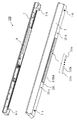
図1は、照明器具100の、反射板2の端板21(図4)を外した側面図である。
図2は、図4のA−A断面図である。
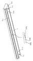
図3、図4は、照明器具100の斜視図である。
図3は、天井を見上げる方向の斜視図である。
図4は、天井側から見下ろす斜視図である。
図5は、透光カバー8のバリエーションを示す図である。
図6は、図2の断面を簡略化した図である。
With reference to FIGS. 1-6, the
FIG. 1 is a side view of the
FIG. 2 is a cross-sectional view taken along the line AA of FIG.
3 and 4 are perspective views of the
FIG. 3 is a perspective view in a direction of looking up at the ceiling.
FIG. 4 is a perspective view looking down from the ceiling side.
FIG. 5 is a view showing a variation of the
FIG. 6 is a simplified view of the cross section of FIG.
(照明器具の構成)
図3、図4等に示すように、照明器具100は、反射板2(器具本体)と、反射板2に収納される光源取付金具3(光源取付部)と、光源取付金具3に取り付けられる電源取付金具4(電源取付部)とを備えている。光源取付金具3と電源取付金具4とは、反射板2に収納される。既設シャーシ1は、蛍光灯用の照明器具の転用品である。照明器具100は、蛍光灯用の照明器具をLED用に転用した器具である。図3において透光カバー8を取り外すと、LEDユニット350a,350b・・・350n(光源ユニットという場合もある)が配置されている。なお、LEDを発光体として用いるのは一例であり、OLEDや他の発光体を用いてユニット化してもよい。
(Structure of lighting equipment)
As shown in FIGS. 3, 4, etc., the
(照明器具100の組付関係)
既設シャーシ1は既に天井に配置されている。電源取付金具4は、図1、図2に示すように、光源取付金具3にネジ6a,6bで取り付けられる。光源取付金具3は、図3、図4に示すように、反射板2に、ねじ10a,10bで取り付けられる。そして、反射板2は、図3、図4に示すように金具5a,5bで既設シャーシ1に取り付けられる。金具5a,5bがねじ7で締め付けられることによって、反射板2が既設シャーシ1に取り付く。なお、本実施の形態では、既設シャーシ1を転用品と想定しているが、新規のものであっても構わない。
(Assembly relationship of lighting apparatus 100)
The existing
(反射板2)
反射板2は金属製である。反射板2は、図3、図4に示すように、長手方向に延びて内部に空間を有する蛍光灯用の逆富士形と同形状の反射板であり、発光面には開口204がある。反射板2は、図2、図6に示すように、反射面として機能する一方の斜面201と、反射面として機能する他方の斜面202とを有する。
(Reflector 2)
The
(光源取付金具3)
図6も参照して説明する。光源取付金具3は金属製である。光源取付金具3は、反射板2の内部の空間に配置され、反射板2の長手方向に延びる長尺形状である。光源取付金具3は、反射板2の長手方向にわたって反射板2の一方の斜面201の裏側の面に対向する第1の斜面301と、反射板2の長手方向にわたって他方の斜面202の裏側の面に対向する第2の斜面302とが、それぞれ一方の斜面201の裏側の面と他方の斜面202の裏側の面とに熱的に接続(範囲51、52)している。「熱的に接続する」とは、この場合、光源取付金具3と反射板2とが面接触することで、熱が伝導することを意味する。光源取付金具3は、反射板2の外部に向けて光を放つ光源ユニット350が取り付けられる。
(Light source mounting bracket 3)
This will be described with reference to FIG. The light
(電源取付金具4)
電源取付金具4は金属製である。電源取付金具4は、光源取付金具3に取り付けられて光源取付金具3と熱的に接続する。ここで「熱的に接続する」とは、上記のとおりである。電源取付金具4は、反射板2の長手方向に延びる長尺形状であり、光源ユニット350を点灯させる新規電源装置11(電源装置)が取り付けられている。なお、図3に示すように、既設シャーシ1には既設電源9が取り付けられている。既設電源9は既設シャーシ1や反射板2を蛍光灯用に使用した際の電源装置であり、新規電源装置11は、既設シャーシ1や反射板2をLED又はOLED用に転用する際の電源装置である。
(Power supply bracket 4)
The power supply mounting bracket 4 is made of metal. The power supply mounting bracket 4 is attached to the light
(空気層)
図6、図4に示すように、光源取付金具3は、平板を折り曲げた折曲形状である。光源取付金具3は、第1の斜面301に対応する第1の側板310と、第2の斜面302に対応する第2の側板320と、第1の側板310と第2の側板320とに対して底面に相当する底板330とを含む折曲形状である。電源取付金具4は、底板330の上面との間に空間401を保って底板330の上面を覆いながら反射板2の長手方向に延びることで空間401を形成している。すなわち、光源取付金具3と電源取付金具4との間には空間401による空気層が存在するので、光源取付金具3が電源取付金具4からもらう「もらい熱」が減少する効果がある。
(Air layer)
As shown in FIGS. 6 and 4, the light
(放熱ルート)
光源取付金具3に取り付けられた新規電源装置11に発生する熱の放熱ルートは以下の様である。新規電源装置11で発生した熱は、新規電源装置11→電源取付金具4→光源取付金具3→反射板2の順に伝導する。この際、光源取付金具3は、反射板2の反射面と面接触している。すなわち、上述のように、光源取付金具3は、第1の斜面301と、第2の斜面302とが、一方の斜面201の裏側の面と他方の斜面202の裏側の面とに熱的に接続している。この場合、図6のように、反射板2の一方の斜面201及び他方の斜面202は、天井面に対して傾斜(θは90度よりも大きい)しているため、この付近は空気が流れやすくなっている。このため、一方の斜面201及び他方の斜面202付近の放熱効果はよい。
(Heat dissipation route)
The heat radiation route of heat generated in the new
(光源ユニットの配置)
また、図3に示すように、反射板2には、逆富士形の頂上に相当する部分203に長手方向に向かう開口204(図3で透光カバー8が反射板2から露出している部分)が形成されている。また、光源取付金具3には、複数の光源ユニット350a〜350nが、開口204の側に反射板2の長手方向に並んで取り付けられる。図3のように照明器具100は、複数のLEDユニットを覆う透光性の透光カバー8を備えている。
(Arrangement of light source unit)
Further, as shown in FIG. 3, the
(透光カバー8のバリエーション)
図5は、透光カバー8の形状を示すための照明器具100の側面図(図2のX矢視)である。
図5の(a)は、平板形状の透光カバー8である。この形状は、照明器具100の直下を明るくする。
図5の(b)は、断面形状が三角形の透光カバー8である。この形状は、照明器具100の側面を明るくする。また、(a)と比較し、配光に広がりをもたせる。
図5の(c)は、断面形状が台形の透光カバー8である。この形状は、照明器具100の直下と側面とを明るくする。また、(a)と比較し、配光に広がりをもたせる。
図5の(d)は、断面形状が円弧の透光カバー8である。この形状は、LEDの光をやわらかくする。
図5の(e)は、断面形状が矩形の透光カバー8である。この形状は、LEDの光を天井側へいきやすくする。
図5の(f)は、断面形状が円から一部円弧を切り欠いた形状の透光カバー8である。この形状は、反射板2を光らせるようにする。
このように、透光カバーの選択により、照明器具直下、天井面、器具意匠面を明るくする。
(Variation of translucent cover 8)
FIG. 5 is a side view of the
FIG. 5A shows a flat plate-shaped
FIG. 5B shows a
(C) of FIG. 5 is the
FIG. 5D shows a
(E) of FIG. 5 is the
FIG. 5F shows a light-transmitting
Thus, the selection of the translucent cover brightens the lighting fixture directly below, the ceiling surface, and the fixture design surface.
以上のように、既設の照明器具の既設シャーシ1を利用して、LED又はOLEDを光源とした灯具を取り付けることができる。
As described above, a lamp using an LED or OLED as a light source can be attached using the existing
灯具の形状は、直管蛍光灯器具の逆富士1灯用又は、逆富士2灯用のソケットがある面にLED又はOLEDの光源を配置する。 The shape of the lamp is such that the LED or OLED light source is arranged on the surface of the straight tube fluorescent lamp fixture having a socket for one inverted Fuji or two inverted Fuji lamps.
実施の形態2.
図7〜図9を参照して実施の形態2を説明する。実施の形態2は、LEDユニットを反射板2の斜面201側、斜面202側の両方の側に配置する構成である。これは、2灯の直管蛍光灯の場合に相当する。
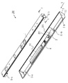
図7は、図8のB−B断面図である。
図8は、実施の形態2の照明器具100の斜視図である。
図9は、透光カバー8の形状のバリエーションを示す図である。
The second embodiment will be described with reference to FIGS.
7 is a cross-sectional view taken along the line BB in FIG.
FIG. 8 is a perspective view of the
FIG. 9 is a view showing variations in the shape of the
図7、図8に示すように、反射板2は、一方の斜面201に長手方向に向かう第1の開口206が形成されると共に、他方の斜面202に長手方向に向かう第2の開口207が形成されている。光源取付金具3には、複数のLEDユニット(図8のLEDユニット350a〜350n)が、第1の開口206の側に反射板の長手方向に並んで第1の斜面301に取り付けられると共に、複数のLEDユニットが、第2の開口207の側に反射板2の長手方向に並んで第2の斜面302に取り付けられている。照明器具100は、第1の開口206側の複数のLEDユニットと、第2の開口側の複数のLEDユニットとを覆う透光性のカバーを備えている。
As shown in FIGS. 7 and 8, the reflecting
(透光カバー8のバリエーション)
図9は、透光カバー8の形状を示すための照明器具100の側面図である。
図9の(a)は、開口206と、開口207との両側に、平板形状の透光カバー8を配置した場合を示している。
図9の(b1)〜(b3)は、開口206と、開口207との両側に透光カバー8を配置している。(b1)は断面が三角形であり、(b2)は三角形の頂点をカットした形状であり、(b2)は三角形の頂点にRをつけた形状である。
図9の(c1)〜(c3)も、開口206と、開口207との両側に透光カバー8を配置している。(c1)〜(c3)は、円弧を基調とした断面形状である。
図9の(d1)〜(d3)は、開口206と、開口207とを覆う単一の透光カバー8を使用する構成である。(d1)〜(d3)は、(b1)〜(b3)と同様に、角を徐々にRに近づけている。
(Variation of translucent cover 8)
FIG. 9 is a side view of the
FIG. 9A shows a case where the flat plate-shaped
In (b1) to (b3) of FIG. 9, the
9 (c <b> 1) to (c <b> 3), the
(D1)-(d3) of FIG. 9 is the structure which uses the single
以上の実施の形態で説明した照明器具100により、以下の効果が得られる。
(1)器具取替えのコストを下げることができる。又、作業者の負荷を下げることができる。
(2)既設の部材を用いるため、省資源化を図ることができる。
(3)電源からの熱を放熱するため、器具の寿命を延ばすことができる。
(4)LEDやOLEDを照明器具に用いた際、発光面の角度により天井面に光が当たらないため、空間の印象が暗くなる傾向があるが、カバー形状を変更することにより、天井面や器具自体に光を当てることや、光源との距離を調節することにより、グレア感を抑えることができる。
The following effects are acquired by the
(1) The cost of equipment replacement can be reduced. In addition, the load on the operator can be reduced.
(2) Since existing members are used, resource saving can be achieved.
(3) Since the heat from the power source is dissipated, the life of the instrument can be extended.
(4) When an LED or OLED is used in a lighting fixture, the ceiling surface does not receive light depending on the angle of the light emitting surface, so the impression of the space tends to be dark, but by changing the cover shape, Glare can be suppressed by applying light to the device itself or adjusting the distance to the light source.
以上の実施の形態では、
長手方向に延び、かつ、内部に空間を有する蛍光灯用の逆富士形の反射板であって、反射面として機能する一方の斜面と、反射面として機能する他方の斜面とを有する逆富士形の反射板の形状をなす金属製の器具本体と、
前記器具本体の前記内部の空間に配置され、前記長手方向に延びる長尺形状であり、前記長手方向にわたって前記器具本体の前記一方の斜面の裏側の面に対向する第1の斜面と、前記長手方向にわたって前記他方の斜面の裏側の面に対向する第2の斜面とが、それぞ
れ前記一方の斜面の裏側の面と前記他方の斜面の裏側の面とに熱的に接続し、前記器具本体の外部に向けて光を放つ光源ユニットが取り付けられた金属製の光源取付部と、
前記光源取付部に取り付けられて前記光源取付部と熱的に接続し、前記長手方向に延びる長尺形状であり、前記光源を点灯させる電源装置が取り付けられた電源取付部と
を備えたことを特徴とする照明器具を説明した。
In the above embodiment,
An inverted Fuji type reflector for a fluorescent lamp that extends in the longitudinal direction and has a space inside, and has one inclined surface that functions as a reflective surface and the other inclined surface that functions as a reflective surface A metal instrument body in the shape of a reflector,
A first inclined surface disposed in the internal space of the instrument body and extending in the longitudinal direction, the first slope facing the back surface of the one slope of the instrument body over the longitudinal direction; A second slope facing the back side surface of the other slope over the direction and thermally connected to the back side surface of the one slope and the back side surface of the other slope, respectively, A light source mounting portion made of metal to which a light source unit that emits light toward the outside is mounted;
A power supply attachment portion attached to the light source attachment portion and thermally connected to the light source attachment portion, extending in the longitudinal direction, and attached with a power supply device for turning on the light source. A featured lighting fixture has been described.
以上の実施の形態では、
前記光源取付部は、
平板を折り曲げた折曲形状であって、前記第1の斜面に対応する第1の側板と、前記第2の斜面に対応する第2の側板と、前記第1の側板と前記第2の側板とに対して底面に相当する底板とを含む折曲形状であり、
前記電源取付部は、
前記底面との間に空間を保って前記底面を覆いながら前記長手方向に延びることを特徴とする照明器具を説明した。
In the above embodiment,
The light source mounting portion is
A bent shape obtained by bending a flat plate, a first side plate corresponding to the first slope, a second side plate corresponding to the second slope, the first side plate, and the second side plate. And a bent shape including a bottom plate corresponding to the bottom surface,
The power supply mounting portion is
The lighting fixture characterized by extending in the longitudinal direction while covering the bottom surface while maintaining a space between the bottom surface and the bottom surface has been described.
以上の実施の形態では、
前記器具本体は、
前記逆富士形の頂上に相当する部分に前記長手方向に向かう開口が形成され、
前記光源取付部は、
複数の前記光源ユニットが、前記開口の側に前記長手方向に並んで取り付けられ、
前記照明器具は、さらに、
前記複数の光源ユニットを覆う透光性のカバーを備えたことを特徴とする照明器具を説明した。
In the above embodiment,
The instrument body is
An opening toward the longitudinal direction is formed in a portion corresponding to the top of the inverted Fuji shape,
The light source mounting portion is
A plurality of the light source units are attached side by side in the longitudinal direction on the opening side,
The lighting apparatus further includes:
A lighting apparatus including a light-transmitting cover that covers the plurality of light source units has been described.
以上の実施の形態では、
前記器具本体は、
前記一方の斜面に前記長手方向に向かう第1の開口が形成されると共に、前記他方の斜面に前記長手方向に向かう第2の開口が形成され、
前記光源取付部は、
複数の前記光源ユニットが、前記第1の開口の側に前記長手方向に並んで前記第1の斜面に取り付けられると共に、複数の前記光源ユニットが、前記第2の開口の側に前記長手方向に並んで前記第2の斜面に取り付けられ、
前記照明器具は、さらに、
前記第1の開口側の前記複数の光源ユニットと、前記第2の開口側の前記複数の光源ユニットとを覆う透光性のカバーを備えたことを特徴とする照明器具を説明した。
In the above embodiment,
The instrument body is
A first opening in the longitudinal direction is formed on the one slope, and a second opening in the longitudinal direction is formed on the other slope,
The light source mounting portion is
A plurality of the light source units are attached to the first slope side by side in the longitudinal direction on the first opening side, and a plurality of the light source units are disposed on the second opening side in the longitudinal direction. Mounted side by side on the second slope,
The lighting apparatus further includes:
There has been described a lighting fixture including a translucent cover that covers the plurality of light source units on the first opening side and the plurality of light source units on the second opening side.
以上の実施の形態では、
前記透光性のカバーは、
前記第1の開口側の前記複数の光源ユニットを覆う第1のカバーと、前記第2の開口側の前記複数の光源ユニットを覆う第2のカバーとの、2つの透光性カバーからなることを特徴とする照明器具を説明した。
In the above embodiment,
The translucent cover is
It consists of two translucent covers, a first cover that covers the plurality of light source units on the first opening side, and a second cover that covers the plurality of light source units on the second opening side. A lighting fixture featuring the above has been described.
以上の実施の形態では、
前記透光性のカバーは、
前記第1の開口側の前記複数の光源ユニットと、前記第2の開口側の前記複数の光源ユニットとを覆う単一の透光性カバーであることを特徴とする照明器具を説明した。
In the above embodiment,
The translucent cover is
There has been described a lighting fixture that is a single translucent cover that covers the plurality of light source units on the first opening side and the plurality of light source units on the second opening side.
以上の実施の形態では、
長手方向に延びる長尺形状であり、一方の面に光を放つ光源ユニットが取り付けられた板部を有する光源取付部と、
前記光源ユニットが取り付けられた前記一方の面の裏面となる前記板部の他方の面に取り付けられ、前記光源ユニットを点灯させる電源装置とを備えた照明器具を説明した。
In the above embodiment,
A light source mounting portion having a long shape extending in the longitudinal direction and having a plate portion to which a light source unit emitting light on one surface is mounted;
The lighting fixture provided with the power supply device attached to the other surface of the said board part used as the back surface of the said one surface where the said light source unit was attached, and lighting the said light source unit was demonstrated.
以上の実施の形態では、
前記照明器具は、
前記長手方向に延びる長手形状であり、前記電源装置が取り付けられる電源取付部を備え、
前記電源装置は、
前記電源取付部を介して前記光源取付部に取り付けられる照明器具を説明した。
In the above embodiment,
The lighting fixture is:
A longitudinal shape extending in the longitudinal direction, comprising a power supply mounting portion to which the power supply device is mounted;
The power supply device
The lighting fixture attached to the light source attachment via the power supply attachment has been described.
以上の実施の形態では、
前記照明器具は、さらに、
前記光源取付部の前記長手方向に延び、かつ、内部に空間を有する器具本体と、
前記器具本体が取り付けられるシャーシと
を備え、
前記器具本体は、
前記空間に、前記光源ユニットと前記電源装置とが取り付けられた前記光源取付部が配置されて、前記シャーシに取り付けられる照明器具を説明した。
In the above embodiment,
The lighting apparatus further includes:
An instrument body extending in the longitudinal direction of the light source mounting portion and having a space inside;
A chassis to which the instrument body is attached;
The instrument body is
The lighting apparatus has been described in which the light source attachment portion to which the light source unit and the power supply device are attached is disposed in the space, and is attached to the chassis.
以上の実施の形態では、
前記シャーシは、
天井に配置される照明器具を説明した。
In the above embodiment,
The chassis is
A lighting fixture placed on the ceiling has been described.
1 既設シャーシ、2 反射板、3 光源取付金具、4 電源取付金具、5 シャーシと反射板を止める金具、6 光源取付金具3と電源取付金具4とを止めるねじ、7 既設シャーシ1と新規反射板2を止めるねじ、8 透光カバー、10 反射板2と光源取付金具3を止めるねじ、11 新規電源装置、100 照明器具、201,202,302,302 斜面、203 頂上に相当する部分、204,206,207 開口、310,320 側板、330 底板、350 LEDユニット、401 空間。
DESCRIPTION OF
Claims (4)
前記長手方向に延びる器具本体であり、
前記長手方向に延びる一方の斜面を持つ第1の斜面板と、
前記長手方向に延びる他方の斜面を持つ第2の斜面板と、
前記第1の斜面板と前記第2の斜面板との前記長手方向に沿う一方の端部どうしを、前記長手方向に沿って延びる一方の側部と他方の側部とで接続する平板形状の平板部と
を有し、
前記平板部により前記一方の端部どうしが接続された状態で前記第1の斜面板と前記第2の斜面板との前記長手方向に沿う他方の端部どうしが互いに離れる方向に前記第1の斜面板と前記第2の斜面板とが傾斜する形状の逆富士形の形状をなし、前記光源取付部が取り付けられる金属製の器具本体と、
前記光源ユニットが取り付けられた前記平面の裏面となる他方の面側に配置された状態で前記器具本体に取り付けられ、前記光源ユニットを点灯させる前記長手方向に延びる形状に形成された電源装置と、
透光性の透光カバーと
を備え、
前記第1の斜面板及び前記第2の斜面板との両方の斜面板と、前記平板部とのいずれかは、前記長手方向に向かう開口が形成されており、
前記透光カバーは、
形成されている前記開口を塞ぐように配置され、前記光源取付部に取り付けられた前記光源ユニットを覆うとともに、
前記開口は、
前記透光カバーの一部と、前記光源ユニットとの間に位置し、
前記透光カバーの前記一部は、
前記開口から前記光源ユニットに向かう方向の前記開口の法線の方向へ見て、前記第1の斜面板の少なくとも一部と前記第2の斜面板の少なくとも一部とを露出させている照明器具。 A light source mounting portion made of metal attached to a plane in which a light source unit that emits light extends in a longitudinal direction;
An instrument body extending in the longitudinal direction,
A first slope plate having one slope extending in the longitudinal direction;
A second slope plate having the other slope extending in the longitudinal direction;
A flat plate-like shape in which one end portion along the longitudinal direction of the first slope plate and the second slope plate is connected by one side portion and the other side portion extending along the longitudinal direction. A flat plate portion,
In a state where the one end portions are connected to each other by the flat plate portion, the other end portions along the longitudinal direction of the first slope plate and the second slope plate are separated from each other in the first direction. A slant plate and the second slant plate have an inverted Fuji shape in which the slant plate is inclined, and a metal instrument body to which the light source mounting part is attached;
A power supply device attached to the instrument body in a state of being arranged on the other surface side which is the back surface of the flat surface to which the light source unit is attached, and formed in a shape extending in the longitudinal direction for lighting the light source unit;
With a translucent translucent cover,
Any one of the slope plates of the first slope plate and the second slope plate, and the flat plate portion is formed with an opening in the longitudinal direction.
The translucent cover is
The light source unit is disposed so as to close the formed opening and covers the light source unit attached to the light source attachment part,
The opening is
Located between a part of the translucent cover and the light source unit ,
The part of the translucent cover is
A luminaire that exposes at least a part of the first slope plate and at least a part of the second slope plate when viewed in the normal direction of the opening in a direction from the opening toward the light source unit. .
前記長手方向に延びる器具本体であり、
前記長手方向に延びる一方の斜面を持つ第1の斜面板と、
前記長手方向に延びる他方の斜面を持つ第2の斜面板と、
を有し、
前記第1の斜面板と前記第2の斜面板との前記長手方向に沿う一方の端部どうしは間隔を保ち、前記第1の斜面板と前記第2の斜面板との前記長手方向に沿う他方の端部どうしが互いに離れる方向に前記第1の斜面板と前記第2の斜面板とが傾斜する形状の逆富士形の形状をなし、
かつ、
前記第1の斜面板と前記第2の斜面板との前記一方の端部どうしの間に前記長手方向に向かう開口が形成され、
前記光源取付部が取り付けられる金属製の器具本体と、
前記光源ユニットが取り付けられた前記平面の裏面となる他方の面側に取り付けられ、前記光源ユニットを点灯させる前記長手方向に延びる形状に形成された電源装置と、
前記開口を塞ぐように配置され、前記光源取付部に取り付けられた前記光源ユニットを覆う透光性の透光カバーと、
を備え、
前記開口は、
前記透光カバーの一部と、前記光源ユニットとの間に位置し、
前記透光カバーの前記一部は、
前記開口から前記光源ユニットに向かう方向の前記開口の法線の方向へ見て、前記第1の斜面板の少なくとも一部と前記第2の斜面板の少なくとも一部とを露出させている照明器具。 A light source mounting portion made of metal attached to a plane in which a light source unit that emits light extends in a longitudinal direction;
An instrument body extending in the longitudinal direction,
A first slope plate having one slope extending in the longitudinal direction;
A second slope plate having the other slope extending in the longitudinal direction;
Have
One end portion along the longitudinal direction of the first slope plate and the second slope plate is maintained at a distance, and along the longitudinal direction of the first slope plate and the second slope plate. The first end plate and the second end plate are inclined in the direction in which the other end portions are separated from each other, and an inverted Fuji shape is formed.
And,
An opening in the longitudinal direction is formed between the one end portions of the first slope plate and the second slope plate,
A metal instrument body to which the light source mounting portion is attached;
A power supply device attached to the other side of the plane to which the light source unit is attached and formed in a shape extending in the longitudinal direction for lighting the light source unit;
A translucent translucent cover that covers the light source unit that is disposed so as to close the opening and is mounted on the light source mounting portion;
With
The opening is
Located between a part of the translucent cover and the light source unit ,
The part of the translucent cover is
A luminaire that exposes at least a part of the first slope plate and at least a part of the second slope plate when viewed in the normal direction of the opening in a direction from the opening toward the light source unit. .
幅方向において互いに対向する部分を有することを特徴とする請求項1または請求項2に記載の照明器具。 The translucent cover is
The lighting fixture according to claim 1, wherein the lighting fixture has portions facing each other in the width direction.
前記第1の斜面板と前記第2の斜面板との間に前記光源取付部が配置されることを特徴とする請求項1から請求項3のいずれか一項に記載の照明器具。 The instrument body is
The lighting device according to any one of claims 1 to 3, wherein the light source mounting portion is disposed between the first slope plate and the second slope plate.
Priority Applications (1)
| Application Number | Priority Date | Filing Date | Title |
|---|---|---|---|
| JP2016174430A JP6335235B2 (en) | 2016-09-07 | 2016-09-07 | lighting equipment |
Applications Claiming Priority (1)
| Application Number | Priority Date | Filing Date | Title |
|---|---|---|---|
| JP2016174430A JP6335235B2 (en) | 2016-09-07 | 2016-09-07 | lighting equipment |
Related Parent Applications (1)
| Application Number | Title | Priority Date | Filing Date |
|---|---|---|---|
| JP2015142731A Division JP6005810B2 (en) | 2015-07-17 | 2015-07-17 | lighting equipment |
Publications (3)
| Publication Number | Publication Date |
|---|---|
| JP2016201378A JP2016201378A (en) | 2016-12-01 |
| JP2016201378A5 JP2016201378A5 (en) | 2017-01-12 |
| JP6335235B2 true JP6335235B2 (en) | 2018-05-30 |
Family
ID=57424358
Family Applications (1)
| Application Number | Title | Priority Date | Filing Date |
|---|---|---|---|
| JP2016174430A Active JP6335235B2 (en) | 2016-09-07 | 2016-09-07 | lighting equipment |
Country Status (1)
| Country | Link |
|---|---|
| JP (1) | JP6335235B2 (en) |
Family Cites Families (4)
| Publication number | Priority date | Publication date | Assignee | Title |
|---|---|---|---|---|
| US3549879A (en) * | 1967-10-13 | 1970-12-22 | Emerson Electric Co | Lighting fixture |
| JP4739157B2 (en) * | 2006-09-21 | 2011-08-03 | 積水樹脂株式会社 | Lighting lamp |
| JP2008218186A (en) * | 2007-03-05 | 2008-09-18 | Mitsubishi Electric Corp | Luminaire |
| JP2010073670A (en) * | 2008-09-22 | 2010-04-02 | Toshiba Lighting & Technology Corp | Led lighting fixture |
-
2016
- 2016-09-07 JP JP2016174430A patent/JP6335235B2/en active Active
Also Published As
| Publication number | Publication date |
|---|---|
| JP2016201378A (en) | 2016-12-01 |
Similar Documents
| Publication | Publication Date | Title |
|---|---|---|
| JP5798674B2 (en) | lighting equipment | |
| JP5508997B2 (en) | lighting equipment | |
| US20100097804A1 (en) | Led lamp | |
| JP2011113876A (en) | Led type illumination device | |
| JP2009129809A (en) | Lighting system | |
| KR101115394B1 (en) | Apparatus for lighting | |
| JP2010198828A (en) | Lighting device | |
| JP5813164B2 (en) | lighting equipment | |
| JP3163443U (en) | LED lighting device | |
| EP2565528B1 (en) | Annular-arranged lamp capable of backward projecting by concave sphere | |
| JP7119601B2 (en) | lighting equipment | |
| JP6586306B2 (en) | LED lighting fixtures | |
| JP2011228286A (en) | Lighting device | |
| JP6094618B2 (en) | lamp | |
| JP6335235B2 (en) | lighting equipment | |
| JP5814451B1 (en) | LIGHTING DEVICE AND LIGHT EMITTING UNIT FOR LIGHTING DEVICE | |
| JP6005810B2 (en) | lighting equipment | |
| JP6251081B2 (en) | Reflection unit and LED module | |
| KR101327917B1 (en) | LED Light Having The Shape Of Fluorescent Tube | |
| JP5933089B2 (en) | Lighting device | |
| TW201447173A (en) | Straight tube lamp and lighting apparatus | |
| JP2019192377A (en) | Lighting device | |
| JP5814449B1 (en) | LIGHTING DEVICE AND LIGHT EMITTING UNIT FOR LIGHTING DEVICE | |
| TWI544170B (en) | Light emitting diode bulb | |
| JP3179283U (en) | Straight tube type LED lamp and LED lighting device |
Legal Events
| Date | Code | Title | Description |
|---|---|---|---|
| A621 | Written request for application examination |
Free format text: JAPANESE INTERMEDIATE CODE: A621 Effective date: 20160907 |
|
| A521 | Request for written amendment filed |
Free format text: JAPANESE INTERMEDIATE CODE: A523 Effective date: 20161124 |
|
| A977 | Report on retrieval |
Free format text: JAPANESE INTERMEDIATE CODE: A971007 Effective date: 20170620 |
|
| A131 | Notification of reasons for refusal |
Free format text: JAPANESE INTERMEDIATE CODE: A131 Effective date: 20170627 |
|
| A521 | Request for written amendment filed |
Free format text: JAPANESE INTERMEDIATE CODE: A523 Effective date: 20170823 |
|
| A131 | Notification of reasons for refusal |
Free format text: JAPANESE INTERMEDIATE CODE: A131 Effective date: 20171114 |
|
| A521 | Request for written amendment filed |
Free format text: JAPANESE INTERMEDIATE CODE: A523 Effective date: 20180111 |
|
| TRDD | Decision of grant or rejection written | ||
| A01 | Written decision to grant a patent or to grant a registration (utility model) |
Free format text: JAPANESE INTERMEDIATE CODE: A01 Effective date: 20180403 |
|
| A61 | First payment of annual fees (during grant procedure) |
Free format text: JAPANESE INTERMEDIATE CODE: A61 Effective date: 20180427 |
|
| R150 | Certificate of patent or registration of utility model |
Ref document number: 6335235 Country of ref document: JP Free format text: JAPANESE INTERMEDIATE CODE: R150 |
|
| R250 | Receipt of annual fees |
Free format text: JAPANESE INTERMEDIATE CODE: R250 |
|
| R250 | Receipt of annual fees |
Free format text: JAPANESE INTERMEDIATE CODE: R250 |
|
| R250 | Receipt of annual fees |
Free format text: JAPANESE INTERMEDIATE CODE: R250 |
|
| R250 | Receipt of annual fees |
Free format text: JAPANESE INTERMEDIATE CODE: R250 |