JP6334989B2 - Delivery arm type sewing machine - Google Patents

Delivery arm type sewing machine Download PDF

Info

Publication number
JP6334989B2
JP6334989B2 JP2014069722A JP2014069722A JP6334989B2 JP 6334989 B2 JP6334989 B2 JP 6334989B2 JP 2014069722 A JP2014069722 A JP 2014069722A JP 2014069722 A JP2014069722 A JP 2014069722A JP 6334989 B2 JP6334989 B2 JP 6334989B2
Authority
JP
Japan
Prior art keywords
bed
sewing machine
arm
shaft
cylinder
Prior art date
Legal status (The legal status is an assumption and is not a legal conclusion. Google has not performed a legal analysis and makes no representation as to the accuracy of the status listed.)
Active
Application number
JP2014069722A
Other languages
Japanese (ja)
Other versions
JP2015188669A (en
JP2015188669A5 (en
Inventor
向井 裕親
裕親 向井
板東 進
進 板東
Original Assignee
ペガサスミシン製造株式会社
Priority date (The priority date is an assumption and is not a legal conclusion. Google has not performed a legal analysis and makes no representation as to the accuracy of the date listed.)
Filing date
Publication date
Application filed by ペガサスミシン製造株式会社 filed Critical ペガサスミシン製造株式会社
Priority to JP2014069722A priority Critical patent/JP6334989B2/en
Priority to CN201510136301.1A priority patent/CN104947334B/en
Priority to TW104109888A priority patent/TWI616571B/en
Publication of JP2015188669A publication Critical patent/JP2015188669A/en
Publication of JP2015188669A5 publication Critical patent/JP2015188669A5/ja
Application granted granted Critical
Publication of JP6334989B2 publication Critical patent/JP6334989B2/en
Active legal-status Critical Current
Anticipated expiration legal-status Critical

Links

Images

Description

本発明は、送り出し腕型ミシンに関するもので、詳しくは、シリンダーの延出方向に生地を送る送り出し腕型ミシンのフレーム構造および駆動機構に関する。
本発明において、前後とは布送り方向における前後方向をいい、左右とはミシンを正面から見たときの左右方向をいう。また上下とはミシンの上下方向をいう。
The present invention relates to a delivery arm type sewing machine, and more particularly to a frame structure and a drive mechanism of a delivery arm type sewing machine that feeds a cloth in the extending direction of a cylinder.
In the present invention, front and rear refer to the front and rear direction in the cloth feeding direction, and left and right refer to the left and right direction when the sewing machine is viewed from the front. The up and down direction means the up and down direction of the sewing machine.

この種の送り出し腕型ミシンとして、シリンダーとアームとが互いに交差する方向にベッドから延出したものが従来より知られている(例えば、特許文献1参照。)。図4乃至図6は特許文献1に開示されるような従来の送り出し腕型ミシンにおけるミシン本体11の外観を示したもので、図4は同ミシンの左側面図、図5は同ミシンの平面図、図6は同ミシンの正面図である。
図4に示すように、シリンダー13はベッド12から布送り方向Fに延出している。アーム14は基部がベッド12に立脚するとともにシリンダー13と交差する方向に水平延伸している。アーム14の先端部は図5に示すようにシリンダー13の先端側に向かって屈折し、該アーム14の先端には頭部15が連設されている。頭部15はシリンダー13先端上面に設けられた針板16上方に配置されている。
頭部15の下面から図示しない針棒,押さえ棒が突出しており、針棒には複数の針が、押さえ棒には押さえ金17がそれぞれ固定されている。押さえ金17には図示しない上下メス,上飾りスプレッダなどが備えられている。また、シリンダー13内には図示しない送り歯,ルーパが備えられている。
As this type of delivery arm type sewing machine, one that extends from a bed in a direction in which a cylinder and an arm intersect each other has been conventionally known (for example, see Patent Document 1). 4 to 6 show the appearance of the sewing machine body 11 in a conventional delivery arm type sewing machine as disclosed in Patent Document 1, FIG. 4 is a left side view of the sewing machine, and FIG. 5 is a plan view of the sewing machine. FIG. 6 and FIG. 6 are front views of the sewing machine.
As shown in FIG. 4, the cylinder 13 extends from the bed 12 in the cloth feeding direction F. The arm 14 stands horizontally on the bed 12 and extends horizontally in a direction crossing the cylinder 13. End of the arm 14 is refracted toward the distal end side of the cylinder over 13 as shown in FIG. 5, the tip of the arm 14 the head 15 is continuously provided. The head 15 is disposed above a needle plate 16 provided on the top surface of the tip of the cylinder 13.
A needle bar and a presser bar (not shown) protrude from the lower surface of the head 15, and a plurality of needles are fixed to the needle bar, and a presser bar 17 is fixed to the presser bar. The presser foot 17 is provided with an upper and lower knife, upper decoration spreader, etc. (not shown). Further, a feed dog and a looper (not shown) are provided in the cylinder 13.

図5に示すように、アーム14内にはアーム14の延伸方向に沿って主軸10(上軸)が配置されている。主軸10の頭部15に近い一端はアーム14外に突出しており、該主軸10の一端にはハンドプーリ29(ハンドホイール)が取着されている。ハンドプーリ29は図示しないモータベルトが担架されて図示しないミシンの駆動源の動力を主軸10に伝えるとともに、ミシン停止時には作業者の手で操作されて主軸10を回動させる。
主軸10の頭部15側には図示しない針棒駆動機構,メス駆動機構,上飾り駆動機構などが連結されており、主軸10の回動によって前記針,メス,上飾りスプレッダなどが駆動する。また、主軸10のアーム14基部側には図示しない複数の偏心ロッドが連結されており、該偏心ロッドはベッド12に配置される図示しない送り歯駆動機構やルーパ駆動機構に接続されている。そして主軸10の回動によって送り歯やルーパが駆動する。
As shown in FIG. 5, the main shaft 10 (upper shaft) is disposed in the arm 14 along the extending direction of the arm 14. One end of the main shaft 10 near the head 15 protrudes outside the arm 14, and a hand pulley 29 (hand wheel) is attached to one end of the main shaft 10. The hand pulley 29 is stretched by a motor belt (not shown) to transmit the power of a driving source of a sewing machine (not shown) to the main shaft 10 and is rotated by the operator's hand when the sewing machine is stopped.
A needle bar drive mechanism, a knife drive mechanism, an upper decoration drive mechanism and the like (not shown) are connected to the head 15 side of the main spindle 10, and the needle, the knife, the upper spreader, etc. are driven by the rotation of the spindle 10. A plurality of eccentric rods (not shown) are coupled to the base of the main shaft 10 on the side of the arm 14, and the eccentric rods are connected to a feed dog driving mechanism and a looper driving mechanism (not shown) arranged on the bed 12. Then, the feed dog and the looper are driven by the rotation of the main shaft 10.

上述のように構成された従来の送り出し腕型ミシンにおいて、シリンダー13上面に積載された生地は該シリンダー13の先端側すなわち布送り方向Fに送られ、上記針,ルーパ等々の各部材が協働して縫製が行われる。特許文献1に開示される送り出し腕型ミシンは、主に2枚の生地または筒状にした生地の左右一対の生地端を突き合せつつ一部を重ね合わせ、その重ね合わせ部分に、二重環縫い目あるいは偏平縫い目を形成するのに用いられる。 In the conventional delivery arm type sewing machine configured as described above, the fabric loaded on the upper surface of the cylinder 13 is fed in the tip side of the cylinder 13, that is, in the fabric feeding direction F, and the members such as the needle and the looper cooperate with each other. Then sewing is performed. The delivery arm type sewing machine disclosed in Patent Document 1 mainly overlaps a pair of left and right fabric ends of two fabrics or a cylindrical fabric, and a double ring is formed on the overlap portion. Used to form seams or flat seams.

特公昭30−5835号公報(第1−2図)Japanese Patent Publication No. 30-5835 (Fig. 1-2)

上述した従来の送り出し腕型ミシンを用いて縫製を行う場合、縫製を行う作業者はミシンの正面、すなわちベッド12の布送り方向Fでいう手前に位置し、上記左右一対の生地端を左右の手に夫々持ち、該生地端を夫々ベッド12の左右側方からシリンダー13上面に差し入れ、針板16の図示しない針落ちに向けて生地を送り込む。縫製中、作業者は正常な縫製を行うため常に針落ち付近を注視する必要があり、この種の従来ミシンの場合はベッド12に立脚するアーム14の基部上方から針落ち付近を視認することになる。   When sewing is performed using the above-described conventional delivery arm type sewing machine, the operator who performs the sewing is positioned in front of the sewing machine, that is, in front of the bed 12 in the cloth feeding direction F, and the pair of left and right fabric ends are moved to the left and right. Holding each of the hands, the ends of the dough are inserted into the upper surface of the cylinder 13 from the left and right sides of the bed 12, respectively, and the dough is fed toward a needle drop (not shown) of the needle plate 16. During sewing, the operator always needs to closely watch the vicinity of the needle drop in order to perform normal sewing. In the case of this type of conventional sewing machine, the vicinity of the needle drop is visually recognized from above the base of the arm 14 that stands on the bed 12. Become.

ところが、従来の送り出し腕型ミシンにおいては、針落ちがシリンダー13先端の針板16上と作業者から離れた位置にあり、作業者はアーム14の基部上面越しに針落ちを視認しなければならない。したがって、作業者は針落ちを注視するためにアーム14の基部上面越しに針落ちに向かって顔を近づけがちになり、そうすると作業者の体、特に胸がアーム14の基部の前面に当たることになる。そして、ミシン駆動に伴い発生する熱や振動が作業者の体に伝わり、作業者の身体に悪影響を及ぼす恐れがあった。
また、上述の複数の偏心ロッドはアーム14の基部からベッド12にわたって配置され、非常に長尺で重量のかさむものとなっていた。したがって、ミシン駆動時に前記複数の偏心ロッドに大きな負荷がかかり、このことがミシン駆動の高速化を阻害する一因となっていた。
However, in the conventional delivery arm type sewing machine, the needle drop is on the needle plate 16 at the tip of the cylinder 13 and at a position away from the worker, and the worker must visually recognize the needle drop through the upper surface of the base of the arm 14. . Accordingly, the operator tends to bring his face closer to the needle drop over the upper surface of the base of the arm 14 in order to watch the needle drop, so that the worker's body, particularly the chest, hits the front of the base of the arm 14. . Then, heat and vibration generated by driving the sewing machine are transmitted to the worker's body, which may adversely affect the worker's body.
Further, the plurality of eccentric rods described above are arranged from the base portion of the arm 14 to the bed 12 and are very long and heavy. Therefore, a large load is applied to the plurality of eccentric rods when the sewing machine is driven, which is one factor that hinders the speeding up of the sewing machine drive.

本発明は、上記問題を解決するためになされたものであり、その目的は、作業者が生地を操作する操作性は維持しつつも、針落ちの視認性を向上させ、もってミシン本体が作業者の体に当たり難い、送り出し腕型ミシンのフレーム構造と駆動機構を提供することにある。   The present invention has been made to solve the above-mentioned problems, and its purpose is to improve the visibility of the needle drop while maintaining the operability for the operator to operate the fabric, so that the sewing machine body can be operated. It is an object of the present invention to provide a frame structure and a driving mechanism of a feeding arm type sewing machine that is difficult to hit a person's body.

上記目的を達成するために、請求項1に記載の発明は、ベッドに基端が接続され布送り方向に延出するシリンダーと、ベッドに基部が連結されシリンダーと交差する方向に水平延出するアームと、アーム先端に連設されシリンダー先端の上方に配置される頭部を備える送り出し腕型ミシンにおいて、前記ベッドは第1ベッド、第1連結部、第2ベッド、第2連結部で構成され、前記シリンダーが接続される第1ベッドと、前記第1ベッドの上部右側面に基部が接続されるとともに上方に延伸する第1連結部と、前記第1連結部の上部先端に基部が接続されるとともに右方へ延伸する第2ベッドと、前記第2ベッドの後面に接続されるとともに前記アームの基部に連結される第2連結部と、前記アーム内に該アームの延伸方向に沿って配置されるとともに軸回りの回動可能に支持される上軸と、前記第2ベッド内に該第2ベッドの延伸方向に沿って配置されるとともに軸回りの回動可能に支持される中間軸と、前記第1ベッド上部から前記第1連結部にわたり布送り方向と直交して配置されるとともに軸回りの回動可能に支持される下軸と、前記下軸の右側と前記中間軸の左側に担架される第1ベルトと、前記上軸と前記中間軸の夫々右側に担架される第2ベルトを備えることを特徴とする。   In order to achieve the above object, the invention according to claim 1 is characterized in that a base end is connected to the bed and extends in the cloth feeding direction, and a base is connected to the bed and extends horizontally in a direction intersecting the cylinder. In a delivery arm type sewing machine comprising an arm and a head that is connected to the tip of the arm and disposed above the tip of the cylinder, the bed comprises a first bed, a first connecting portion, a second bed, and a second connecting portion. A first bed to which the cylinder is connected; a base connected to an upper right side of the first bed and a first connecting part extending upward; and a base connected to an upper end of the first connecting part. And a second bed extending rightward, connected to the rear surface of the second bed and connected to the base of the arm, and disposed in the arm along the extending direction of the arm Is And an upper shaft that is rotatably supported about the axis, an intermediate shaft that is disposed in the second bed along the extending direction of the second bed and is rotatably supported about the axis, A lower shaft disposed perpendicularly to the cloth feeding direction from the upper portion of the first bed to the first connecting portion and supported to be rotatable around an axis, and is stretched on the right side of the lower shaft and the left side of the intermediate shaft. And a second belt stretched on the right side of each of the upper shaft and the intermediate shaft.

請求項2の発明は、請求項1の送り出し腕型ミシンにおいて、前記第1連結部は上方に行くにつれ後方に傾斜していることを特徴とする。
請求項3の発明は、請求項1または2の送り出し腕型ミシンにおいて、前記上軸の右端にミシンの駆動源が接続され、前記中間軸の右端にハンドホイールが取着されることを特徴とする。
According to a second aspect of the present invention, in the delivery arm type sewing machine of the first aspect, the first connecting portion is inclined backward as it goes upward.
The invention of claim 3 is the delivery arm type sewing machine according to claim 1 or 2, wherein a drive source of the sewing machine is connected to the right end of the upper shaft, and a handwheel is attached to the right end of the intermediate shaft. To do.

請求項1の発明によれば、ベッド上にアームが立脚していないので、針落ちに対する作業者の視認性が向上し、もって作業者の体がアームないしベッドに当たり難い。また、第1ベッド右方の懐は十分に確保されているので、作業者の右手をシリンダー上面に差し入れるのに支障はなく、もって作業者が生地を操作する作業性を損ねることはない。さらに、第2ベッドやアームの内部や表面に広いスペースが確保され、もって縫製に必要な各機構を配置できる。
また、以上のように作業者の操作性を維持しつつも視認性を向上させたミシン本体の形状にあって、第1ベッドに配置される送り歯,ルーパなどの各駆動機構は同じく第1ベッドに配置される下軸に連結されて駆動される。そして、前記各駆動機構と下軸とを連結する偏心ロッドなどの連結部材は従来例に比して短尺,軽量化され、もって該連結部材の負荷を軽減することができる。
According to the first aspect of the present invention, since the arm is not standing on the bed, the visibility of the operator with respect to the needle drop is improved, so that the operator's body is difficult to hit the arm or the bed. In addition, since the pocket on the right side of the first bed is sufficiently secured, there is no hindrance to inserting the operator's right hand into the cylinder upper surface, and the workability of the operator to operate the dough is not impaired. Furthermore, a wide space is secured in the interior and surface of the second bed and arm, so that each mechanism necessary for sewing can be arranged.
Further, as described above, the shape of the sewing machine main body is improved in visibility while maintaining the operability of the operator, and each drive mechanism such as a feed dog and a looper arranged on the first bed is also the first. It is connected to a lower shaft arranged on the bed and driven. A connecting member such as an eccentric rod that connects each of the drive mechanisms and the lower shaft is shorter and lighter than the conventional example, and the load on the connecting member can be reduced.

請求項2の発明によれば、、第1連結部の作業者に対する圧迫感が減じられ、また作業者が針落ちに向けて顔を近づけ易くなる。
請求項3の発明によれば、作業者にとって安全かつ操作し易い位置にハンドホイールが配置されることになる。
According to the second aspect of the present invention, the pressure of the first connecting portion against the operator is reduced, and the operator can easily approach the face toward the needle drop.
According to the invention of claim 3, the handwheel is disposed at a position that is safe and easy for the operator to operate.

本発明の送り出し腕型ミシンのミシン本体を示す概略斜視図。The schematic perspective view which shows the sewing machine main body of the delivery arm type sewing machine of this invention. 同上ミシンのミシン本体を示す概略左側面図。The schematic left view which shows the sewing machine main body of a sewing machine same as the above. 同上ミシンのミシン本体を正面やや上方から見た概略図。The schematic which looked at the sewing machine main body of the sewing machine same as the above from the front a little. 従来の送り出し腕型ミシンのミシン本体を示す左側面図。The left view which shows the sewing machine main body of the conventional delivery arm type sewing machine. 同上ミシンのミシン本体を示す一部破断平面図。The partially broken top view which shows the sewing machine main body of a sewing machine same as the above. 同上ミシンのミシン本体を示す正面図。The front view which shows the sewing machine main body of a sewing machine same as the above.

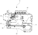
以下、図面を参照して、本発明の実施形態のミシン本体1について説明する。なお、ミシン本体1の外殻を形成する部位については、2点鎖線にて示してある。第1ベッド2の後面下部にはシリンダー3の基端が接続され、シリンダー3の先端は送り方向Fに水平に延出している。シリンダー3先端部上面に針板9が備えられており、針板9には針落ち9aが設けられている。図2に示すように、第1ベッド2は左側方から見て5角形を呈しており、前面2bの上側は上に行くにつれて送り方向Fつまり後方に向かって傾斜している。また、第1ベッド2の上面2aは送り方向Fに向かって下方つまり後ろ下がりに傾斜している。   Hereinafter, a sewing machine body 1 according to an embodiment of the present invention will be described with reference to the drawings. The part forming the outer shell of the sewing machine body 1 is indicated by a two-dot chain line. The base end of the cylinder 3 is connected to the lower part of the rear surface of the first bed 2, and the tip of the cylinder 3 extends horizontally in the feed direction F. A needle plate 9 is provided on the top surface of the tip of the cylinder 3, and the needle plate 9 is provided with a needle drop 9a. As shown in FIG. 2, the first bed 2 has a pentagonal shape when viewed from the left side, and the upper side of the front surface 2b is inclined toward the feeding direction F, that is, toward the rear as it goes upward. Further, the upper surface 2a of the first bed 2 is inclined downward toward the feeding direction F, that is, rearwardly downward.

図1,図3に示すように、第1ベッド2の上部右側面には第1連結部6の基部が接続されており、第1連結部6は該基部より後方に傾斜しつつ上方へ延伸している。第1連結部6の前記基部の下面はシリンダー3の上面よりも高く位置づけられている。第1連結部6の上部先端には第2ベッド7の基部が接続されており、第2ベッド7は該基部より右方へ水平に延伸している。第2ベッド7の延伸方向は、布送り方向Fと直交している。   As shown in FIGS. 1 and 3, the base portion of the first connecting portion 6 is connected to the upper right side surface of the first bed 2, and the first connecting portion 6 extends upward while tilting backward from the base portion. doing. The lower surface of the base portion of the first connecting portion 6 is positioned higher than the upper surface of the cylinder 3. The base of the second bed 7 is connected to the top end of the first connecting portion 6, and the second bed 7 extends horizontally to the right from the base. The extending direction of the second bed 7 is orthogonal to the cloth feeding direction F.

第2ベッド7の右側後面には第2連結部8の一端が接続されており、第2連結部8の他端はアーム4の基部前面に接続されている。アーム4はその基部から左方つまりシリンダー側に向かって延伸し、その左端には頭部5が接続されている。頭部5はシリンダー3上面に設けられた針板9の上方に位置づけられている。頭部5やシリンダー3の内部には縫い目を形成するための各機構が設けられており、また頭部5の下方には図示しない複数の針や押さえ金が配置されているが、これらは従来既知のものであり、説明を省略する。また、アーム4の前面や第2ベッド7の後面には、針糸や飾り糸の繰り出しを制御する天秤,カムなどの糸繰り部材、およびこれらの糸流れを案内する糸案内部材が設けられている。 One end of the second connecting portion 8 is connected to the right rear surface of the second bed 7, and the other end of the second connecting portion 8 is connected to the base front surface of the arm 4. The arm 4 extends from the base to the left, that is, toward the cylinder, and a head 5 is connected to the left end. The head 5 is positioned above a needle plate 9 provided on the upper surface of the cylinder 3. Each mechanism for forming a seam is provided inside the head 5 and the cylinder 3, and a plurality of needles and pressers (not shown) are arranged below the head 5. Since it is a known one, its description is omitted. The front surface of the arm 4 and the rear surface of the second bed 7 are provided with a balance for controlling the feeding of the needle yarn and the decorative yarn, a yarn feeding member such as a cam, and a yarn guiding member for guiding the flow of these yarns. Yes.

図1や図3に示すように、アーム4の延伸方向も布送り方向Fと直交している。つまり、アーム4と第2ベッド7とは平行に配置されている。そして、アーム4,第2連結部8,第2ベッド7は上から見て”コ”の字状に連結されている。   As shown in FIGS. 1 and 3, the extending direction of the arm 4 is also orthogonal to the cloth feeding direction F. That is, the arm 4 and the second bed 7 are arranged in parallel. The arm 4, the second connecting portion 8, and the second bed 7 are connected in a "U" shape when viewed from above.

アーム4内には該アーム4の延伸方向に沿って上軸18が配置されている。上軸18は軸回りの回動可能にアーム4に支持され、右端がアーム4の右側面から右方に突出し、左端は頭部5内に突出している。アーム4の右側面にはミシン本体1の駆動源であるモータ23が取り付けられており、上軸18の右端はモータ23の図示しないモータ軸と連結されている。
第2ベッド7内には該第2ベッド7の延伸方向に沿って中間軸19が配置されている。中間軸19は軸回りの回動可能に第2ベッド7に支持され、右端が第2ベッド7の右側面から右方に突出し、該突出する右端にはハンドホイール24が取着されている。
第1ベッド2上部から第1連結部6下部にわたって、下軸20が左右方向に沿って配置されている。下軸20は軸回りの回動可能にされて、その右端は第1連結部6に、左端は第1ベッド2に夫々支持されている。図1乃至図3に示すように、上軸18,中間軸19,下軸20は互いに平行かつ布送り方向Fに直交して配置されている。また、上軸18と中間軸19とは同じ高さに位置づけられ、下軸20は上軸18および中間軸19よりも低い位置に配置されている。
An upper shaft 18 is disposed in the arm 4 along the extending direction of the arm 4. The upper shaft 18 is supported by the arm 4 so as to be rotatable around the axis, and the right end protrudes rightward from the right side surface of the arm 4 and the left end protrudes into the head 5. A motor 23 as a drive source for the sewing machine body 1 is attached to the right side surface of the arm 4, and the right end of the upper shaft 18 is connected to a motor shaft (not shown) of the motor 23.
An intermediate shaft 19 is disposed in the second bed 7 along the extending direction of the second bed 7. The intermediate shaft 19 is supported by the second bed 7 so as to be rotatable about the axis, and the right end protrudes rightward from the right side surface of the second bed 7, and the handwheel 24 is attached to the protruding right end.
The lower shaft 20 is disposed along the left-right direction from the upper portion of the first bed 2 to the lower portion of the first connecting portion 6. The lower shaft 20 is rotatable about the axis, and the right end is supported by the first connecting portion 6 and the left end is supported by the first bed 2. As shown in FIGS. 1 to 3, the upper shaft 18, the intermediate shaft 19, and the lower shaft 20 are arranged in parallel to each other and perpendicular to the cloth feeding direction F. Further, the upper shaft 18 and the intermediate shaft 19 are positioned at the same height, and the lower shaft 20 is disposed at a position lower than the upper shaft 18 and the intermediate shaft 19.

上軸18のアーム4内右端側にはプーリ25が固定されており、中間軸19の第2ベッド7内右端側にはプーリ26が固定されている。第2ベルト22は第2連結部8を通じてかつプーリ25,プーリ26を介して上軸18および中間軸19に担架されている。
中間軸19の左端側にはプーリ27が固定されており、下軸20の第1連結部6内右端側にはプーリ28が固定されている。第1ベルト21は第1連結部6の延伸方向に沿って配置されてかつプーリ27,プーリ28を介して中間軸19および下軸20に担架されている。
上軸18はアーム4内または頭部5内において図示しない針棒,メス,上飾りスプレッダなどの各駆動機構に連結されている。また、下軸20は第1ベッド2内において図示しない複数の偏心ロッドを介して同じく図示しない送り歯,ルーパなどの各駆動機構に連結されている。モータ23の駆動によって上軸18が回動すると、上軸18の回動は第2ベルト22,中間軸19,第1ベルト21を介して下軸20に伝達され、下軸20は上軸18に同調して回動する。
A pulley 25 is fixed to the right end side in the arm 4 of the upper shaft 18, and a pulley 26 is fixed to the right end side in the second bed 7 of the intermediate shaft 19. The second belt 22 is stretched on the upper shaft 18 and the intermediate shaft 19 through the second connecting portion 8 and via the pulleys 25 and 26.
A pulley 27 is fixed to the left end side of the intermediate shaft 19, and a pulley 28 is fixed to the right end side in the first connecting portion 6 of the lower shaft 20. The first belt 21 is arranged along the extending direction of the first connecting portion 6 and is stretched by the intermediate shaft 19 and the lower shaft 20 via the pulley 27 and the pulley 28.
The upper shaft 18 is connected to each drive mechanism such as a needle bar, a knife, and an upper spreader (not shown) in the arm 4 or the head 5. Further, the lower shaft 20 is connected to each drive mechanism such as a feed dog and a looper (not shown) via a plurality of eccentric rods (not shown) in the first bed 2. When the upper shaft 18 is rotated by driving the motor 23, the rotation of the upper shaft 18 is transmitted to the lower shaft 20 via the second belt 22, the intermediate shaft 19, and the first belt 21, and the lower shaft 20 is transmitted to the upper shaft 18. Rotate in sync with.

以上のように構成されたミシン本体1を有する送り出し腕型ミシンにおいて、作業者が縫製作業を行うとき、作業者は第1ベッド2の前面2bに対峙し、作業者の目はアーム4上面とほぼ同じ高さか、あるいはアーム4上面の上方に位置することになる。このとき、図3に示すように、第1ベッド2の上方には従来の送り出し腕型ミシンのようにアームが立脚していないため、作業者はアーム4上面より低く位置づけられている第1ベッド2の上面2a越しに針板9の針落ち9a付近を容易に視認することができる。したがって、作業者は針落ち9aを注視するために体をミシン本体1に近づける必要がないため、作業者の体がミシン本体1の第1ベッド2などに接触し、もってミシン本体1から発生する熱や振動が作業者の体に伝わり作業者に悪影響を及ぼす恐れがない。   In the delivery arm type sewing machine having the sewing machine main body 1 configured as described above, when an operator performs a sewing operation, the operator faces the front surface 2b of the first bed 2 and the operator's eyes are on the upper surface of the arm 4 and They are located at almost the same height or above the upper surface of the arm 4. At this time, as shown in FIG. 3, since the arm is not standing on the upper side of the first bed 2 unlike the conventional delivery arm type sewing machine, the worker is positioned lower than the upper surface of the arm 4. 2 near the needle drop 9a of the needle plate 9 can be easily seen through the upper surface 2a. Accordingly, since the operator does not need to bring his body close to the sewing machine main body 1 in order to watch the needle drop 9a, the operator's body comes into contact with the first bed 2 of the sewing machine main body 1 and the like, and is generated from the sewing machine main body 1. There is no risk of heat and vibration being transmitted to the worker's body and adversely affecting the worker.

また、図3に示すように、第1ベッド2の右側方には上部を除きアーム4と連結される部位が存在しておらず、第1連結部6の下部右側方にも連結される部位が存在しない。つまり第1ベッド2の右方の懐は十分に広く、ミシン本体1は作業者が右手をシリンダー3上面に差し入れて生地を針落ち9aに向かって送り出す際に、右腕の肘から先はもちろんのこと、二の腕もミシン本体1に当たり難い構造となっており、もって作業者の作業性を損ねないというものである。 Further, as shown in FIG. 3, there is no portion connected to the arm 4 except for the upper portion on the right side of the first bed 2, and the portion connected to the lower right side of the first connecting portion 6. Does not exist. That bosom of the first right of the bed 2 is sufficiently wide, when the sewing machine main body 1 to begin feeding toward the fabric pledged to cylinder 3 the upper surface of the right hand operator to the needle drop 9a, ahead of course from the right arm of the elbow In other words, the second arm has a structure that is difficult to hit the sewing machine main body 1 so that the workability of the operator is not impaired.

さらに、本実施例のように第1ベッド2の上面2aを後ろ下がりに傾斜する構造とすれば、作業者から見て針落ち9a手前側の視野が広がり、針落ち付近の視認性がいっそう向上することとなる。また、第1ベッド前面2bの上部や第1連結部6を上に行くにつれて後方へ傾斜する構造とすれば、作業者に対する圧迫感が減じられるとともに、作業者が針落ち9aに向けて顔を近づけても作業者の体がミシン本体1により当たり難くなる。   Further, when the upper surface 2a of the first bed 2 is inclined backward and downward as in the present embodiment, the field of view on the front side of the needle drop 9a as viewed from the operator is widened, and the visibility near the needle drop is further improved. Will be. Moreover, if it is made into the structure which inclines back as the upper part of the 1st bed front surface 2b and the 1st connection part 6 go up, while a feeling of oppression with respect to an operator will be reduced, an operator will face the needle drop 9a toward the needle drop 9a. Even if they are close to each other, the operator's body is difficult to hit by the sewing machine body 1.

さらに、前述のようにアーム4と第2ベッド7を平行に配置し、両者の右側にて第2連結部8によってコの字に連結する構造としたので、アーム4や第2ベッド7内には縫い目を形成するための各機構を収容するスペースが十分に確保され、またアーム4前面や第2ベッド7後面には前記各機構に連結される部材、例えば図示しない針糸繰り部材などを配置するスペースが十分に確保されることとなる。   Further, as described above, the arm 4 and the second bed 7 are arranged in parallel, and are connected to the U shape by the second connecting portion 8 on the right side of the both, so that the arm 4 and the second bed 7 are inside. The space for storing each mechanism for forming the seam is sufficiently secured, and a member connected to each mechanism such as a needle thread reel member (not shown) is arranged on the front surface of the arm 4 and the rear surface of the second bed 7. Sufficient space will be secured.

上述したように、本実施例のミシン本体1は縫製に対する作業者の操作性は維持されつつも、作業者の針落ちに対する視認性を向上させ、かつアーム内部や表面のスペースを大きく確保したものとなっている。このような形状のミシン本体1にあって、以上説明したような上軸18,中間軸19,下軸20,第1ベルト21,第2ベルト22の配置および連結によって、第1ベッド2に配置される各駆動機構は下軸20に連結されて下軸20の回動に同調して駆動する。下軸20はアーム4に配置される上軸18よりも低い位置に配置されており、第1ベッド2に配置される各機構と下軸20とを連結する複数の偏心ロッドは、従来例すなわち上軸と連結されるものと比して当然に短尺,軽量なものとなり、もってミシン駆動時に偏心ロッドにかかる負荷が軽減され、ミシンの高速化を図ることができる。 As described above, the sewing machine main body 1 of the present embodiment has improved the operator's operability with respect to sewing while improving the operator's visibility against needle dropping and ensuring a large space inside the arm and on the surface. It has become. The sewing machine body 1 having such a shape is arranged on the first bed 2 by the arrangement and connection of the upper shaft 18, the intermediate shaft 19, the lower shaft 20, the first belt 21, and the second belt 22 as described above. Each drive mechanism connected to the lower shaft 20 is driven in synchronization with the rotation of the lower shaft 20. The lower shaft 20 is disposed at a position lower than the upper shaft 18 disposed on the arm 4, and a plurality of eccentric rods connecting the respective mechanisms disposed on the first bed 2 and the lower shaft 20 are, Naturally, it is shorter and lighter than that connected to the upper shaft, so that the load applied to the eccentric rod during driving of the sewing machine is reduced, and the speed of the sewing machine can be increased.

また、上述の従来例において、ハンドホイール(ハンドプーリ29)はアーム14の頭部15側の主軸10先端、つまり作業者とはアーム14を挟んだ反対側に配置されており、作業者の操作しやすい位置にはなかった。一方、本実施例においては、ハンドホイール24は中間軸19の右端に取着されているので、ハンドホイール24は第2ベッド7の右側面と、作業者にとって操作し易くかつ安全な位置に配置されている。   Further, in the above-described conventional example, the hand wheel (hand pulley 29) is disposed at the tip of the main shaft 10 on the head 15 side of the arm 14, that is, on the opposite side of the operator from the arm 14, and is operated by the operator. It was not in an easy position. On the other hand, in the present embodiment, since the handwheel 24 is attached to the right end of the intermediate shaft 19, the handwheel 24 is disposed on the right side surface of the second bed 7 and at a position that is easy to operate and safe for the operator. Has been.

なお、本発明は以上説明した実施例に限定されるものではなく、例えば、ミシン本体1の各部位を左右対称に配置した送り出し腕型ミシンも、本発明の趣旨を逸脱しないものであり、上記実施例と同様の効果を奏するものである。   The present invention is not limited to the embodiment described above. For example, a delivery arm type sewing machine in which each part of the sewing machine body 1 is arranged symmetrically does not depart from the spirit of the present invention. The same effect as the embodiment is achieved.

1 ミシン本体
2 第1ベッド
2a 上面
2b 前面
3 シリンダー
4 アーム
5 頭部
6 第1連結部
7 第2ベッド
8 第2連結部
9 針板
9a 針落ち
18 上軸
19 中間軸
20 下軸
21 第1ベルト
22 第2ベルト
23 モータ
24 ハンドホイール
F 布送り方向
DESCRIPTION OF SYMBOLS 1 Sewing machine main body 2 1st bed 2a Upper surface 2b Front surface 3 Cylinder 4 Arm 5 Head 6 1st connection part 7 2nd bed 8 2nd connection part 9 Needle plate 9a Needle drop 18 Upper shaft 19 Intermediate shaft 20 Lower shaft 21 First Belt 22 Second belt 23 Motor 24 Handwheel F Cloth feed direction

Claims (3)

ベッドに基端が接続され布送り方向に延出するシリンダーと、ベッドに基部が連結されシリンダーと交差する方向に水平延出するアームと、アーム先端に連設されシリンダー先端の上方に配置される頭部を備える送り出し腕型ミシンにおいて、前記ベッドは第1ベッド、第1連結部、第2ベッド、第2連結部で構成され、前記シリンダーが接続される第1ベッドと、前記第1ベッドの上部右側面に基部が接続されるとともに上方に延伸する第1連結部と、前記第1連結部の上部先端に基部が接続されるとともに右方へ延伸する第2ベッドと、前記第2ベッドの後面に接続されるとともに前記アームの基部に連結される第2連結部と、前記アーム内に該アームの延伸方向に沿って配置されるとともに軸回りの回動可能に支持される上軸と、前記第2ベッド内に該第2ベッドの延伸方向に沿って配置されるとともに軸回りの回動可能に支持される中間軸と、前記第1ベッド上部から前記第1連結部にわたり布送り方向と直交して配置されるとともに軸回りの回動可能に支持される下軸と、前記下軸の右側と前記中間軸の左側に担架される第1ベルトと、前記上軸と前記中間軸の夫々右側に担架される第2ベルトを備えることを特徴とする、送り出し腕型ミシン。   A cylinder with a base connected to the bed and extending in the cloth feeding direction, an arm with a base connected to the bed and extending horizontally in a direction intersecting the cylinder, and a cylinder connected to the tip of the arm and disposed above the tip of the cylinder In the delivery arm type sewing machine having a head, the bed is composed of a first bed, a first connecting portion, a second bed, and a second connecting portion, and the first bed to which the cylinder is connected, and the first bed A first connecting part having a base connected to the upper right side and extending upward; a second bed having a base connected to the upper end of the first connecting part and extending right; and a second bed A second connecting portion connected to the rear surface and connected to the base portion of the arm, an upper shaft disposed in the arm along the extending direction of the arm and supported rotatably about the axis; Above An intermediate shaft disposed in the two beds along the extending direction of the second bed and supported so as to be rotatable about an axis, and orthogonal to the cloth feeding direction from the upper portion of the first bed to the first connecting portion. A lower shaft that is rotatably supported around the shaft, a first belt that is suspended on the right side of the lower shaft and the left side of the intermediate shaft, and on the right side of the upper shaft and the intermediate shaft, respectively. A delivery arm type sewing machine comprising a second belt to be stretched. 前記第1連結部は上方に行くにつれ後方に傾斜していることを特徴とする、請求項1に記載の送り出し腕型ミシン。   2. The delivery arm type sewing machine according to claim 1, wherein the first connecting portion is inclined backward as it goes upward. 前記上軸の右端にミシン駆動原が接続され、前記中間軸の右端にハンドホイールが取着されることを特徴とする、請求項1または2に記載の送り出し腕型ミシン。   The delivery arm type sewing machine according to claim 1, wherein a sewing machine driving source is connected to a right end of the upper shaft, and a hand wheel is attached to a right end of the intermediate shaft.
JP2014069722A 2014-03-28 2014-03-28 Delivery arm type sewing machine Active JP6334989B2 (en)

Priority Applications (3)

Application Number Priority Date Filing Date Title
JP2014069722A JP6334989B2 (en) 2014-03-28 2014-03-28 Delivery arm type sewing machine
CN201510136301.1A CN104947334B (en) 2014-03-28 2015-03-26 Arm-outtake type sewing machine
TW104109888A TWI616571B (en) 2014-03-28 2015-03-27 Feed arm type sewing machine

Applications Claiming Priority (1)

Application Number Priority Date Filing Date Title
JP2014069722A JP6334989B2 (en) 2014-03-28 2014-03-28 Delivery arm type sewing machine

Publications (3)

Publication Number Publication Date
JP2015188669A JP2015188669A (en) 2015-11-02
JP2015188669A5 JP2015188669A5 (en) 2017-04-27
JP6334989B2 true JP6334989B2 (en) 2018-05-30

Family

ID=54423697

Family Applications (1)

Application Number Title Priority Date Filing Date
JP2014069722A Active JP6334989B2 (en) 2014-03-28 2014-03-28 Delivery arm type sewing machine

Country Status (1)

Country Link
JP (1) JP6334989B2 (en)

Families Citing this family (2)

* Cited by examiner, † Cited by third party
Publication number Priority date Publication date Assignee Title
TWI585262B (en) * 2015-12-25 2017-06-01 Ming Jang Sewing Machine Co Ltd Curved arm type sewing machine structure
JP7388809B2 (en) * 2017-09-25 2023-11-29 Juki株式会社 Feed-out arm type double chainstitch sewing machine

Family Cites Families (4)

* Cited by examiner, † Cited by third party
Publication number Priority date Publication date Assignee Title
US1928486A (en) * 1931-01-31 1933-09-26 Lewis Invisible Stitch Machine Sewing machine frame
US2623484A (en) * 1948-03-19 1952-12-30 Singer Mfg Co Feed-off-the-arm sewing machine
GB1460969A (en) * 1974-03-13 1977-01-06 Singer Co Feed-off-the-arm sewing machine
JP6210774B2 (en) * 2013-07-24 2017-10-11 ペガサスミシン製造株式会社 Feeding mechanism of feeding arm type sewing machine

Also Published As

Publication number Publication date
JP2015188669A (en) 2015-11-02

Similar Documents

Publication Publication Date Title
JP6210774B2 (en) Feeding mechanism of feeding arm type sewing machine
JP4725864B2 (en) Flat stitch sewing machine
JP2015036116A (en) Apparatus for whipping button sewing thread
TWI640669B (en) Feed arm type sewing machine
JP6334989B2 (en) Delivery arm type sewing machine
JP7138360B2 (en) 2-needle lockstitch machine
JP5957227B2 (en) Buttonhole sewing machine
JP2005334234A (en) Cylinder type valance stitch sewing machine
JP6335045B2 (en) Delivery arm type sewing machine
JP6364214B2 (en) Delivery arm type sewing machine
CN202175841U (en) Sewing machine
JP2015188669A5 (en)
TWI616571B (en) Feed arm type sewing machine
JP2007029641A (en) Fringe sewing machine
JP6343185B2 (en) Delivery arm type sewing machine
JP6371887B2 (en) Feeding mechanism of feeding arm type sewing machine
JP5421327B2 (en) Manufacturing method of bonded fabric, manufacturing apparatus thereof, bonded fabric, and fabric with long body
JPH08131678A (en) Walking sewing machine
JP3868805B2 (en) Sewing machine with root winding button
JP5420606B2 (en) Intermittent stitch sewing machine
JP6537056B2 (en) 2-needle lockstitch sewing machine
US258736A (en) Horace fishes
TWI392782B (en) Flat-seam sewing machine and selvage-cutting transmission device thereof
TWI271457B (en) The forward and backward moving racks with a differential feeding mechanism for a horizontal cylindrical sewing machine
CN105887370B (en) Tailoring machine and left and right substrate sheet pairing method of sewing

Legal Events

Date Code Title Description
A521 Request for written amendment filed

Free format text: JAPANESE INTERMEDIATE CODE: A523

Effective date: 20170323

A621 Written request for application examination

Free format text: JAPANESE INTERMEDIATE CODE: A621

Effective date: 20170323

TRDD Decision of grant or rejection written
A01 Written decision to grant a patent or to grant a registration (utility model)

Free format text: JAPANESE INTERMEDIATE CODE: A01

Effective date: 20180403

A61 First payment of annual fees (during grant procedure)

Free format text: JAPANESE INTERMEDIATE CODE: A61

Effective date: 20180427

R150 Certificate of patent or registration of utility model

Ref document number: 6334989

Country of ref document: JP

Free format text: JAPANESE INTERMEDIATE CODE: R150

R250 Receipt of annual fees

Free format text: JAPANESE INTERMEDIATE CODE: R250

R250 Receipt of annual fees

Free format text: JAPANESE INTERMEDIATE CODE: R250

R250 Receipt of annual fees

Free format text: JAPANESE INTERMEDIATE CODE: R250

S533 Written request for registration of change of name

Free format text: JAPANESE INTERMEDIATE CODE: R313533

R350 Written notification of registration of transfer

Free format text: JAPANESE INTERMEDIATE CODE: R350