JP6334555B2 - Electromagnetic switch with stable movable contact - Google Patents
Electromagnetic switch with stable movable contact Download PDFInfo
- Publication number
- JP6334555B2 JP6334555B2 JP2015546531A JP2015546531A JP6334555B2 JP 6334555 B2 JP6334555 B2 JP 6334555B2 JP 2015546531 A JP2015546531 A JP 2015546531A JP 2015546531 A JP2015546531 A JP 2015546531A JP 6334555 B2 JP6334555 B2 JP 6334555B2
- Authority
- JP
- Japan
- Prior art keywords
- contact
- movable contact
- contacts
- electromagnetic switch
- switch according
- Prior art date
- Legal status (The legal status is an assumption and is not a legal conclusion. Google has not performed a legal analysis and makes no representation as to the accuracy of the status listed.)
- Active
Links
Images


Classifications
-
- H—ELECTRICITY
- H01—ELECTRIC ELEMENTS
- H01H—ELECTRIC SWITCHES; RELAYS; SELECTORS; EMERGENCY PROTECTIVE DEVICES
- H01H50/00—Details of electromagnetic relays
- H01H50/54—Contact arrangements
- H01H50/56—Contact spring sets
- H01H50/58—Driving arrangements structurally associated therewith; Mounting of driving arrangements on armature
-
- H—ELECTRICITY
- H01—ELECTRIC ELEMENTS
- H01H—ELECTRIC SWITCHES; RELAYS; SELECTORS; EMERGENCY PROTECTIVE DEVICES
- H01H1/00—Contacts
- H01H1/06—Contacts characterised by the shape or structure of the contact-making surface, e.g. grooved
-
- H—ELECTRICITY
- H01—ELECTRIC ELEMENTS
- H01H—ELECTRIC SWITCHES; RELAYS; SELECTORS; EMERGENCY PROTECTIVE DEVICES
- H01H1/00—Contacts
- H01H1/12—Contacts characterised by the manner in which co-operating contacts engage
- H01H1/14—Contacts characterised by the manner in which co-operating contacts engage by abutting
- H01H1/20—Bridging contacts
- H01H1/2075—T-shaped bridge; bridging contact has lateral arm for mounting resiliently or on a pivot
-
- H—ELECTRICITY
- H01—ELECTRIC ELEMENTS
- H01H—ELECTRIC SWITCHES; RELAYS; SELECTORS; EMERGENCY PROTECTIVE DEVICES
- H01H50/00—Details of electromagnetic relays
- H01H50/12—Ventilating; Cooling; Heating
-
- H—ELECTRICITY
- H01—ELECTRIC ELEMENTS
- H01H—ELECTRIC SWITCHES; RELAYS; SELECTORS; EMERGENCY PROTECTIVE DEVICES
- H01H50/00—Details of electromagnetic relays
- H01H50/54—Contact arrangements
- H01H50/546—Contact arrangements for contactors having bridging contacts
-
- H—ELECTRICITY
- H01—ELECTRIC ELEMENTS
- H01H—ELECTRIC SWITCHES; RELAYS; SELECTORS; EMERGENCY PROTECTIVE DEVICES
- H01H2235/00—Springs
- H01H2235/01—Spiral spring
-
- H—ELECTRICITY
- H01—ELECTRIC ELEMENTS
- H01H—ELECTRIC SWITCHES; RELAYS; SELECTORS; EMERGENCY PROTECTIVE DEVICES
- H01H50/00—Details of electromagnetic relays
- H01H50/16—Magnetic circuit arrangements
- H01H50/18—Movable parts of magnetic circuits, e.g. armature
- H01H50/30—Mechanical arrangements for preventing or damping vibration or shock, e.g. by balancing of armature
- H01H50/305—Mechanical arrangements for preventing or damping vibration or shock, e.g. by balancing of armature damping vibration due to functional movement of armature
Description
(関連出願の相互参照)
本出願は、2012年12月10日付出願の米国特許仮出願第61/735128号の出願日の利益を主張し、該出願の全内容は本明細書に組み入れられる。
(Cross-reference of related applications)
This application claims the benefit of the filing date of US Provisional Application No. 61/735128, filed Dec. 10, 2012, the entire contents of which are incorporated herein.
電気自動車等の各種用途は、種々の電力線の開閉を制御するためのコンタクタ及びリレーを使用することを必要とする。一定の条件の下では、電気自動車及び/又は他の電気装置類は、可聴ノイズ及び/又は振動を生成し得る。 Various applications such as electric vehicles require the use of contactors and relays for controlling the opening and closing of various power lines. Under certain conditions, electric vehicles and / or other electrical devices may generate audible noise and / or vibration.
第1の態様では、電磁スイッチは、少なくとも2つの固定電気コンタクト(stationary electric contact)と、可動コンタクト(moveable contact)とを備え、前記電磁スイッチは、前記可動コンタクトが前記固定電気コンタクトとの接触状態と非接触状態をもたらす往復運動をするように構成され、前記可動コンタクトは、前記往復運動において少なくとも3つの接点が生じ、かつ前記少なくとも3つの接点によって画定される三角形がその運動の力の中心を取り囲むように構成される。 In the first aspect, the electromagnetic switch includes at least two stationary electric contacts and a movable contact, and the electromagnetic switch has a state in which the movable contact is in contact with the fixed electric contact. The movable contact has at least three contacts in the reciprocating motion, and a triangle defined by the at least three contacts is centered on the force of the motion. Constructed to surround.
発明の実施形態は、次に述べる特徴のいずれか又は全てを含み得る。第1及び第2の固定電気コンタクトが存在し、前記可動コンタクトは、前記固定電気コンタクトに対して3つの接点が生ずるように構成され、第1及び第2の接点は前記第1の固定電気コンタクト上に生じ、前記第3の接点は前記第2の固定電気コンタクト上に生ずる。前記電磁スイッチは、少なくとも1つの平坦な面を有する矩形の金属ブロックから形成され、前記金属ブロックは、前記平坦な面に前記第1及び第2の接点を形成するための第1の凹部を有し、かつ前記第3の接点を形成するための前記2及び第3の凹部を有する。シャフトのための開口が、前記力の中心において前記金属ブロックを貫通し、前記シャフトは前記可動コンタクトを駆動する。 Embodiments of the invention may include any or all of the following features. There are first and second stationary electrical contacts, the movable contact is configured to have three contacts with respect to the stationary electrical contact, and the first and second contacts are the first stationary electrical contact. And the third contact occurs on the second stationary electrical contact. The electromagnetic switch is formed of a rectangular metal block having at least one flat surface, and the metal block has first recesses for forming the first and second contacts on the flat surface. And the second and third recesses for forming the third contact. An opening for the shaft passes through the metal block at the center of the force, and the shaft drives the movable contact.
第1及び第2の固定電気コンタクトと、少なくとも1つの非導電性機械的コンタクトとが存在し、前記可動コンタクトは、前記第1の固定電気コンタクトと第1の接点を生じ、前記第2の固定コンタクトと第2の接点を生じ、かつ前記非導電性機械的コンタクトと第3の接点を生ずるように構成される。前記非導電性機械的コンタクトは、前記第3の接点が前記往復運動の末端で生じて前記往復運動の別の部分にある間では生じないように配置される。前記電磁スイッチは、前記非導電性機械的コンタクトと熱的に接触するヒートシンクを更に含む。前記電磁スイッチは、前記往復運動の開始時に前記可動コンタクトによって接触される別の非導電性機械的コンタクトを更に含む。前記非導電性機械的コンタクトは、前記第3の接点が前記往復運動の間に継続して生ずるように配置される。前記電磁スイッチは、前記非導電性機械的コンタクトと熱的に接触するヒートシンクを更に含む。前記電磁スイッチは別の非導電性機械的コンタクトを更に含み、前記可動コンタクトは前記往復運動の間に継続して両機械的コンタクトの間に制限される。前記非導電性機械的コンタクトは、前記可動コンタクトの前記電磁スイッチへの取り付け部を含む。前記取り付け部は、前記往復運動を許容する曲げ部材を含む。前記電磁スイッチは、前記取り付け部と熱的に接触するヒートシンクを更に含む。 There are first and second stationary electrical contacts and at least one non-conductive mechanical contact, and the movable contact provides a first contact with the first stationary electrical contact, and the second stationary electrical contact. A second contact is made with the contact, and a third contact is made with the non-conductive mechanical contact. The non-conductive mechanical contact is positioned so that the third contact occurs at the end of the reciprocation and does not occur while in another part of the reciprocation. The electromagnetic switch further includes a heat sink that is in thermal contact with the non-conductive mechanical contact. The electromagnetic switch further includes another non-conductive mechanical contact that is contacted by the movable contact at the start of the reciprocation. The non-conductive mechanical contact is positioned such that the third contact continues during the reciprocation. The electromagnetic switch further includes a heat sink that is in thermal contact with the non-conductive mechanical contact. The electromagnetic switch further includes another non-conductive mechanical contact, the movable contact being continuously limited between the two mechanical contacts during the reciprocation. The non-conductive mechanical contact includes an attachment portion of the movable contact to the electromagnetic switch. The attachment portion includes a bending member that allows the reciprocating motion. The electromagnetic switch further includes a heat sink that is in thermal contact with the mounting portion.
前記可動コンタクトは、前記3つの接点に対応する実質的に三角の形状を有する。前記実質的に三角の形状は、少なくとも1つの切頭角部(頂部が切り欠かれた角)を有する。第1、第2、及び第3の固定電気コンタクトが存在し、前記可動コンタクトは、少なくとも1つの接点が前記第1、第2、及び第3の固定電気コンタクトの各々と生ずるように構成される。前記第1、第2、及び第3の固定電気コンタクトは、前記接点が前記往復運動の末端で生じ、前記往復運動の別の部分にある間では生じないように配置される。前記可動コンタクトは、ばね付勢される。 The movable contact has a substantially triangular shape corresponding to the three contact points. The substantially triangular shape has at least one truncated corner (corner with a truncated top). There are first, second, and third stationary electrical contacts, and the movable contact is configured such that at least one contact occurs with each of the first, second, and third stationary electrical contacts. . The first, second, and third stationary electrical contacts are arranged such that the contact occurs at the end of the reciprocation and does not occur while in another part of the reciprocation. The movable contact is spring biased.
前記運動の力の中心は、前記少なくとも3つの接点によって画定される三角形の重心から離れた位置にある。 The center of the force of motion is located away from the center of gravity of the triangle defined by the at least three contacts.
本発明の実施形態は、次に述べる利点のいずれか又は全てを提供し得る。スイッチにおけるコンタクタは、三角接点の幾何学的特徴を組み込むことによって機械的に安定な電気コンタクトを提供することができる。大きい振幅の電流から生ずる電気力学的運動又は振動性の不安定さを、取り除くか低減させることができる。 Embodiments of the present invention may provide any or all of the advantages described below. Contactors in the switch can provide mechanically stable electrical contacts by incorporating the geometric features of triangular contacts. Electrodynamic motion or oscillatory instabilities resulting from large amplitude currents can be eliminated or reduced.
本明細書は、それぞれ往復運動させられる可動コンタクトを有し、往復運動の間に少なくとも3つの接点が生ずる電磁スイッチの複数の実施例について記載している。いくつかの実施形態では、可動コンタクトは、同様に電磁スイッチの一部である複数の固定コンタクトと少なくとも3つの接点を形成する。いくつかの実施形態では、2つの接点が複数の固定コンタクトに対して形成され、第3の接点は非導電性機械的コンタクトのような別のコンタクトと形成され得る。前記3つの接点によって画定される三角形は、可動コンタクトの動きを駆動する力の中心を取り囲む。例えば、そのような構成により、使用中に可動コンタクトで生じ得る望ましくない共振によって引き起こされるノイズを除去又は低減することができる。 This specification describes several embodiments of electromagnetic switches, each having a movable contact that can be reciprocated, with at least three contacts occurring during reciprocation. In some embodiments, the movable contact forms at least three contacts with a plurality of stationary contacts that are also part of the electromagnetic switch. In some embodiments, two contacts can be made to a plurality of fixed contacts and a third contact can be made with another contact, such as a non-conductive mechanical contact. The triangle defined by the three contacts surrounds the center of the force that drives the movement of the movable contact. For example, such a configuration can eliminate or reduce noise caused by undesirable resonances that can occur with movable contacts during use.
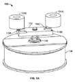
図1A及び図1Bは、それぞれ電磁スイッチ100の立面図と断面図である。いくつかの実施形態では、スイッチは、電気モータのパワーエレクトロニクスの一部である。例えば、電気自動車はインバータに電磁スイッチ群を有することがあり、電磁スイッチ群はインバータにおいて、バッテリー又は他の蓄電手段からのDCを、モータを駆動するためのACに変換するために用いられる。本実施例では、1つの電磁スイッチのみが図示されており、その部品のいくつかは明示のために図示されていない。とはいえ、本明細書に明示的には記載されていない特性や態様に関して、当該電磁スイッチは従来型のスイッチと同様又は同一に動作し得る。
1A and 1B are an elevation view and a sectional view of the
電磁スイッチ100は、固定コンタクト104A及び104Bに対して接触状態になったり、非接触状態となったりするように動かされるべく構成される可動コンタクト102を有する。例えば、両固定コンタクトは、それぞれ電気回路の正(+)及び負(−)の端子と考えることができる。閉位置では、可動コンタクトは両固定コンタクトとの間に電路を形成する。例えば、これにより、電流は固定コンタクトの一方から他方に流れることが可能となる。
The
電磁スイッチ100は、シャフト108を作動させるソレノイド106を有する。詳細には、ソレノイドは、その内部においてシャフト108に接続されるアーマチャ110と相互作用して、シャフトを駆動して往復運動させる。可動コンタクト102はシャフトに取り付けられる。例えば、シャフトのための開口112が可動コンタクトに形成される。開口は、本実施例に示すように、可動コンタクトの厚さ全体を貫通する孔であり得る。
The
シャフト及び可動コンタクトの往復運動は、1つ以上のばねによって促進され得る。いくつかの実施形態では、可動コンタクトはばね付勢される。例えば、ここでは、らせんばね114がソレノイドの外側にて可動コンタクト102とソレノイドの上部との間でシャフト108の周囲に配置される。別の例として、ここでは、ばね116がソレノイドの内側にてアーマチャ110とソレノイドの上部との間でシャフトの周囲に配置されている。
The reciprocation of the shaft and movable contact can be facilitated by one or more springs. In some embodiments, the movable contact is spring biased. For example, here, a
図2は、従来技術のコンタクト200を示す。ここに示すコンタクト200は閉位置にあり、コンタクトが固定コンタクト202A及び202B間の電路を導通させている。固定コンタクトの各々は、コンタクトの寸法より大きい曲率半径を有する円筒形の面のような、コンタクトに対向する非平面的な面を有し得る。コンタクトはばね付勢され、シャフト204によって固定コンタクトとの接触状態と非接触状態との間を移動可能である。
FIG. 2 shows a
コンタクト200が使用されているとき、いくつかの望ましくない影響が生じ得る。種々の理由のために、コンタクトは、共振又は他の振動にさらされることがあり、これがもたらし得る状態の例を2、3挙げるとすれば、望ましくないノイズ又は抵抗の上昇等が挙げられる。例えば、コンタクトは、シャフト204を通る長手軸206の周りで振動することがある。そのような振動は、長手軸の周囲でコンタクトに作用するトルクによって生じる、又は増大し得る。
When the
図1を再度参照すると、可動コンタクト102は、固定コンタクト104A及び104Bと複数の接点を形成するべく構成されている。例えば可動コンタクトは、固定コンタクト104Bに対する領域118Aと、固定コンタクト104Aに対する領域118B及び118Cとを有し得る。領域118A〜118Cは、対応する接点がシャフト108の周囲に特定の形で位置するように配置されている。これのいくつかの例について、以下説明する。
Referring back to FIG. 1, the
図3は、一方の固定コンタクト104A及び104Bと他方の可動コンタクト(明示のため図示省略)との間に形成された、接点領域302A〜302Cによって画定される三角形300を概略的に示す。即ち、可動コンタクト102(図1A及び図1B)が閉位置にあるとき、可動コンタクトは、固定コンタクトと領域302A〜302C内でそれぞれ接点を形成する。接点の各々は、固定コンタクトと可動コンタクトとの間を流れる電流に関連している。この例では、三角形300は二等辺三角形である。他の実施形態では、接点は他の種類の三角形を形成し得る。いくつかの実施形態では、可動コンタクトと複数の固定コンタクトのいくつか又は全ては限定された曲率半径を有する。
FIG. 3 schematically illustrates a
中心304は、可動コンタクトに力が作用する場所を示す。中心304は、領域302B及び302Cの間に直接には位置しておらず、むしろ領域302Aの側に方向に位置をずらせて配置されている。いくつかの実施形態では、コンタクトの往復運動がシャフト(図示せず)によって駆動される場合、中心304の位置はシャフトに一致する。別の例として、駆動力が2つ以上の位置でコンタクトに作用する場合、中心304は、コンタクトを駆動する力の中心を示す。
The
中心304は、三角形300によって取り囲まれている。即ち、可動コンタクトは、それが領域302A〜302C内で固定コンタクトと接点を形成するときに、これらの接点がコンタクトの動きを駆動する力の中心を取り囲む三角形を形成するように構成される。即ち、接点のどの2つをとっても、それらを結ぶ直線上に中心304が存在することはない。
The
いくつかの実施形態では、中心304は、接点によって形成されるそのような三角形の重心に一致する。他の実施形態では、その中心は、(形成される三角形に囲まれてはいるが)重心からは離れた位置にある。
In some embodiments, the
図4は、図1A及び図1Bにおける可動コンタクト102の斜視図を示す。可動コンタクトは、平坦な面402を有する矩形の金属ブロック400から形成される。更に、金属ブロックは、平坦な面に形成された凹部402A〜402Cを有する。凹部402A及び402Bは、ここでは、ブロックの一端の対応する角部に位置しており、それによって接触領域118Aを形成する。凹部402Cは、同様に、金属ブロックの短い端部に沿って他の2つの角部の間に位置し、それによって接触領域118B及び118Cを形成する。例えば、凹部は、金属ブロックを機械加工することによって形成することができる。別の例として、金属ブロックは、所望の形状に鋳造することができる。この図では、シャフトは現時点で開口112内に存在していない。
FIG. 4 shows a perspective view of the
図5は、図1A及び図1Bにおける可動コンタクト102の側面図を示す。ここでは、矩形の金属ブロックの側面が示されており、凹部402Aが見える。凹部402B及び開口112は、仮想線で示される。
FIG. 5 shows a side view of the
可動コンタクトは、意図される実施形態に基づいて、選択される特性を有するように製造することができる。例示的な実施形態では、コンタクトは導電性材料(例えば、金属)から作製され、ある一定の長さ、幅、高さを有し、凹部はそれぞれの特定の寸法を有する。ここに述べた特性のいずれか又は全てを、実施形態に関連する1つ以上の要因に基づいて選択することができる。例えば、限定を意図しないが、そのような要因として、以下のものを挙げることができる。
スイッチにおいて使用されることが期待される電圧及び/又は電流の大きさ。
コンタクトの往復運動の速度及び/又は駆動力。
固定コンタクトの上面のサイズ及び/又は形状。
製造及び/又は材料のコスト。
The movable contact can be manufactured to have selected properties based on the intended embodiment. In an exemplary embodiment, the contacts are made from a conductive material (eg, metal) and have a certain length, width and height, and the recesses have respective specific dimensions. Any or all of the characteristics described herein can be selected based on one or more factors associated with the embodiment. For example, although not intended to be limited, examples of such factors include the following.
The magnitude of voltage and / or current expected to be used in the switch.
The speed and / or driving force of the contact reciprocation.
The size and / or shape of the upper surface of the fixed contact.
Manufacturing and / or material costs.
図6は、追加のコンタクトを有する電磁スイッチ600の一例を示す。一般的には、スイッチは、開閉されるべき外部の回路に接続される端子を有する固定電気コンタクト602を少なくとも2つ含む。図示された見え方では、固定電気コンタクトの1つが他の電気コンタクトの背後に位置しており、従ってここでは見えていない。可動コンタクト604は、アクチュエータ606(例えば可動コンタクトに取り付けられたプランジャに結合される磁石に作用するソレノイド等)によって往復運動するように駆動される。これらの構成部品は、外部に対する電気的な絶縁を提供し、かつ内部を液体や破片から保護する非導電性材料の筐体のようなハウジング608上に取り付けられるか、又はその内部に包入される。作用する力はfaで示され、可動コンタクトにおける、力の中心と呼ばれることもある点に作用する。
FIG. 6 shows an example of an
電磁スイッチ600は、可動コンタクトを機械的に安定化させる意図で設けられた少なくとも1つの追加のコンタクト612を備える。いくつかの実施形態では、これは、非導電性機械的コンタクトである。例えば、その機械的コンタクトは、ハウジング608と同じ材料から(例えば、その表面上に一体的に形成される突出部として)作製されるか、又は別の絶縁性材料から作製され得る。往復運動の末端においては、可動コンタクトは、それが両方の固定電気コンタクト602に加えて追加のコンタクト612に接触する位置614にある。従って、これにより、少なくとも固定コンタクト602の間での電気的接続を形成する。少なくとも3つの接点が存在することが、可動コンタクトにおける振動の発生を防止又は低減させる高められた剛性を生じさせる。
The
アクチュエータ606が可動コンタクト604をコンタクト602から離れるように動かすと、そのように形成された電気的接続は切断されることになる。可動コンタクト604は、多かれ少なかれ固定的な方式で即ち規制される形でアクチュエータ606に接続され得る。例えば、可動コンタクトがシャフトに取り付けられているとき、適用可能な製造誤差及び/又は関連する材料の特性が、コンタクトの取り付けにおいていくつかの役割を担うことができる。これにより、可動コンタクトは、往復運動の1つ以上の段階においてある程度水平面から離れるように傾斜させることも可能にできる。しかし、コンタクトの傾斜が大きすぎる場合には、コンタクト604が離れた方向に動いても、固定電気コンタクトの両方又はいずれか一方との接点が残った状態になる(又は再接触する)ことも起こり得る。その場合、電気的接続は完全には切断されず、スイッチが満足に動作できなくなる。
When the
可動コンタクト604は、往復運動の途中の少なくとも部分的に1つ以上の方法で動きを規制され得る。いくつかの実施形態では、可動コンタクトの一方の端部が追加のコンタクト612から離れて移動しすぎないように規制するコンタクト616を設けることができる。例えば、これにより、可動コンタクトの他方の端部が、固定電気コンタクト602のいずれかに接触するのを防止することができる。コンタクト616はハウジング608に取り付けられるか、又はハウジングの一部として一体的に形成することができる。
The
他の例として、可動コンタクト604は、その往復運動の間中ほぼ継続してその一方の端部がコンタクト616上に載るように構成することができる。そのような実施形態のいくつかでは、追加のコンタクト612は、突出度を小さく形成するか、又は完全に取り除くこともできる。
As another example,
追加のコンタクト612及び/又は機械的コンタクト616は、可動コンタクト604に対する接点を提供することに加えて、1つ以上の他の目的のために使用することができる。例えば、可動コンタクト604に電流が流れると、コンタクト及び電磁スイッチ600の残部に通電抵抗熱が発生する。いくつかの実施形態では、スイッチは、スイッチから熱を放散させる役目を果たし得る、ハウジング608に結合された1つ以上のヒートシンク618を含む。これは、スイッチの可動コンタクトと周囲環境との間での熱的接触の追加の経路を提供し得る。
任意の適切な種類のヒートシンクを用いることができ、そのようなヒートシンクとして、限定を意図しないが、スイッチの周囲の環境中に延出する非孤立型の放熱フィンが挙げられる。例えば、追加のコンタクト612が、ハウジング608の壁に一体化されている場合には、追加のコンタクトは、可動コンタクトからの熱がヒートシンクに伝達されるように、比較的薄い壁の材料から形成することができる。即ち、ヒートシンクを含む、導体、材料塊、又は熱交換部材等を、電熱性のグリース、ペースト、ろう付け具、接着剤等によって、追加のコンタクトの可動コンタクトとは反対側に熱的に密接させることができる。いくつかの実施形態では、ヒートシンクが固定コンタクト602から電気的に絶縁されるので、流体による冷却を容易に行うことができる。例えば、追加のコンタクトに熱交換用流体チャネルを組み込んで、コンタクトから冷却用流体への直接の熱交換を行うことができる。
Any suitable type of heat sink can be used, and such heat sinks include, but are not limited to, non-isolated radiating fins that extend into the environment surrounding the switch. For example, if the
いくつかの例では、コンタクト612及び/又は616は非導電性機械的コンタクトである。例えば、コンタクトは、特定の実施形態の電気的及び他の特性を考慮して、十分な絶縁性を有する任意の適切な材料から作製することができる。
In some examples,
しかし、他の実施形態では、コンタクト612及び/又は616は、電気コンタクトであり得る。これにより、その実施形態のために利用可能な材料の種類を増やすことが可能となり、例えば選択された材料を、より頑強で、より摩擦が小さく、より伝熱性が高く(又は低く)、及び/又はより耐衝撃性が高いものとすることができる。次に可動コンタクト604は、往復運動の一端の位置にて少なくとも3つの別々の電気的接点と接触する。例えば、これにより、1つのコンタクトを入力用とし、他の2つを出力用とすることが可能となる。別の例として、2つの電気コンタクトを(例えば、追加のコンタクト612を固定コンタクト602の1つに)電気的に接続しておくことができる。いくつかの実施形態では、この電気的接続部は絶縁性のハウジング材料に取り付けることができる。ハウジングが導電性材料を含む他の実施形態では、電気コンタクトと導電性ハウジングとの間に、絶縁性スペーサ、固定具、又は他の層(例えば接着剤)を配設することができる。
However, in other embodiments, the
図7は、実質的に三角の形状を有する可動コンタクト700の一例を示す。ここで、可動コンタクトは、固定コンタクト702、704、及び706とともに図示されており、可動コンタクトが力の中心708においてアクチュエータ(明示のために図示せず)によって駆動されると、少なくとも接点a、b、及びcが形成されるように構成される。例えば、固定コンタクト702は非導電性機械的コンタクトで、他の2つの固定コンタクトは導電性であり得る。別の例として、3つのコンタクト702〜706が全て導電性であり得る。
FIG. 7 shows an example of a
通常は、力の中心708は、可動コンタクトに対するシャフトの取り付け方に起因して可動コンタクト700に対して実質的に固定される。しかし、上記したように、可動コンタクトは、ある程度の回転の自由度を有し得る。例えば、可動コンタクトが、接点b及びcの間の直線b−cと平行な軸周りに回転する場合、この回転により、接点b及びcが、b−cと駆動力faの両方に対して垂直な方向に可動コンタクトの表面上を動くことになる。この回転運動が駆動力faと組み合わせられることで、可動コンタクト上のトルク又はモーメント、即ち力の中心708と直線b−cとの間の距離710を乗じたトルクの評価量が生成されることになる。例えば、生成された力は、可動コンタクトの角度変位の単調関数であり、かつ可動コンタクトを角度平衡状態に戻そうとする向きを持つものとされ得る。可動コンタクトと固定コンタクト704〜706との間に表面接触のゼロスリップ状態が存在する場合には、この回転の結果、b−cと駆動力faの両方に対して垂直な方向への可動コンタクトの平行移動も生じ得る。
Normally, the
いくつかの状況では、固定電気コンタクト704と706との間を、可動コンタクトを介して大電流が流れると、自立的で電気機械的な揺動が励起されることになる。この状態は、電流がDCである場合に観察されたが、電流がACである場合にも同様の挙動が生じ得ると考えられる。この動きは、コンタクタの性能や予測寿命に悪影響を与える。例えば、コンタクト間での過渡的電圧降下及びコンタクタにおける電力損失は構成部品の材料を劣化させることがあり、また過渡的なアーク放電はコンタクト材料の再配分及びコンタクトの幾何学的形態の劣化をもたらすことがある。
In some situations, when a large current flows between the stationary
ここで、コンタクト702で形成された接点aは、直線b−cによって定められる可動コンタクトの回転軸周りの剛性を提供し、これは望ましくない回転及び/又は平行移動を防止又は低減することができる。可動コンタクトは、接点a、b、及びcが、限定しないが、正三角形又は直角二等辺三角形を含むあらゆる適切な三角の形状を形成するように形成され得る。力の中心708は、ここでは三角形a−b−cの内側に位置している。この構成及び他の構成は、3点a、b、及びcの全てが正の垂直抗力をもって接触する状態で機械的に安定的となる剛性の高い本体システムに相当する。例えば、力の中心708は、直線b−cから距離710だけ離され、同様に力の中心は接点aから距離712だけ離される。距離710及び712は、可動コンタクトが往復運動で移動する距離と比較して、相対的に短いものであり得る。いくつかの実施形態では、距離710及び712は互いに異なる比率を有し得る。
Here, the contact a formed by the
接点a、b、及びcの各角部では、可動コンタクト700が、切頭側部を有する。例えば、接点b及びcに対応する切頭側部はここでは互いに平行であり、接点aの切頭側部に対して垂直である。可動コンタクトは、2つ以上の切頭側部の間において曲線をなす形状の縁部を有し得る。
At each corner of the contacts a, b, and c, the
上述の例では、可動コンタクトは、角度に関して2つの自由度を有する。即ち、直線b−cに平行かつ力の中心708を通る軸線周りの回転及び力の中心708と接点aとをつなぐ軸線周りの回転である。いくつかの実施形態では、可動コンタクトの動きに対する必要な規制が、可動コンタクト自体の自由度に対する規制となるように設計され得る。例えば上述の軸線周りの許容される回転は、可動コンタクトのアクチュエータに対する適切な接続によって規制され得る。可動コンタクトが、純粋な直線運動を行うように規制されて可動コンタクトの孔を貫通する駆動ロッドによってアクチュエータに取り付けられる場合には、可動コンタクトと駆動ロッドとの間の嵌め合いにおける寸法許容差の適切な選択が動きの規制としての役目を果たし得る。前記許容差に対する機械的摩耗の影響についても適宜考慮されなければならない。
In the above example, the movable contact has two degrees of freedom with respect to angle. That is, the rotation around the axis parallel to the straight line bc and passing through the center of
faによって定められる軸線周りの可動コンタクトの回転運動も規制されることが必要であるか、望ましいことであり得る。例えば、可動コンタクトの形状が三角である場合は、規制は、可動コンタクトと固定コンタクトとの間の接点が適切に形成されることを確実にするように利用され得る。例えば、fa軸周りでの可動コンタクトの±60°の回転により、可動コンタクタが動作できない状態に置かれる。この実施形態では、1つ以上の追加の(機械的又は電気的)コンタクトに組み込まれた特徴、又はそのコンタクトの近傍に配置された補助的な特徴(例えばポスト)によって、いくつかの形態の規制が与えられ得る。他方、可動コンタクトが、力の中心の周りの回転について十分対称的である場合には、コンタクタは、あらゆる回転位置において正しく動作することになる。例えば、回転について完全に対称的であるならば、可動コンタクトは円盤状であり三角形ではない。 It may be necessary or desirable that the rotational movement of the movable contact about the axis defined by f a is also restricted. For example, if the shape of the movable contact is triangular, the restriction can be utilized to ensure that the contact between the movable contact and the stationary contact is properly formed. For example, rotation of ± 60 ° of the movable contacts around f a shaft, placed in a state in which the movable contactor can not operate. In this embodiment, some form of regulation is achieved by features incorporated into one or more additional (mechanical or electrical) contacts, or auxiliary features (eg, posts) located near the contacts. Can be given. On the other hand, if the movable contact is sufficiently symmetric about rotation about the center of force, the contactor will operate correctly at any rotational position. For example, if it is completely symmetrical about rotation, the movable contact is disk-shaped and not triangular.
図8は、実質的に三角の形状を有する可動コンタクト800の別の例を示す。可動コンタクトは、固定コンタクト802、804、及び806とともに図示されており、接点にも同様にa、b、及びcの符合が付されている。可動コンタクトは、駆動力faによって力の中心808で駆動される。ここでは、接点aが形成される可動コンタクトの角部は、固定コンタクト802A及び802Bの間に実質的に動きを規制される。例えば、固定コンタクト802A及び802Bの間隔の大きさは、可動コンタクトの適切な厚さに基づいて選択することができ、それにより可動コンタクトの(接点b及びcを有する)他方の側が、駆動力faによって上下にある一定の幅だけ動くことが可能となる。この例では、可動コンタクトは実質的に一様な厚さを有し、正三角形を形成している。いくつかの実施形態では、コンタクト802は非導電性で、他の電気コンタクトは電気コンタクトであり得、他の実施形態では、コンタクト802〜806の全てが電気コンタクトであり得る。
FIG. 8 shows another example of a
図9は、実質的に三角の形状を有する可動コンタクト900の別の例を示す。固定コンタクト902、904、及び906が図示されている。また、接点a、b、及びc、並びに力の中心908も示されている。
FIG. 9 shows another example of a
接点a、b、及びcの各角部において、可動コンタクト900は、切頭側部を有する。例えば、ここでは、接点b及びcに対応する切頭側部は互いに平行であり、接点aの切頭側部に対して垂直である。また、可動コンタクトは、各接点に対応する切頭側部を互いに結合する直線的な縁部を有する。
At each corner of the contacts a, b, and c, the
使用中におけるコンタクトの機械的摩耗及び変形により、接点が、その意図された又は元の位置からずれる傾向が生じ得る。例えば、接点aは、ここでは可動コンタクトの中央線からずれて、接点bよりcの側に近づいている。同様に、接点b及びcは、両者が元の位置から互いに接近するように互いに逆方向に位置がずれている。即ち、たとえ接点の各々が、初めはそれぞれに対応する各コンタクトの中心に位置するように配置されていたとしても、その接点は、図示された位置のように移動してしまう。しかし、可動コンタクトは、そのような摩耗/変形にも関わらず、接点によって形成される三角910が、依然として力の中心908を取り囲むように構成される。このことが、可動コンタクトの安定性及び剛性を維持する助けとなる。
The mechanical wear and deformation of the contact during use can cause the contact to tend to deviate from its intended or original position. For example, the contact a is deviated from the center line of the movable contact here and is closer to the c side than the contact b. Similarly, the positions of the contacts b and c are shifted in the opposite directions so that they approach each other from the original position. That is, even if each of the contacts is initially arranged to be located at the center of each corresponding contact, the contact moves as shown in the figure. However, the movable contact is configured such that, despite such wear / deformation, the
図10は、追加のコンタクトを有する電磁スイッチ1000の別の例を示す。ここでは、駆動力faにより、可動コンタクト1002の、固定コンタクト1004との接触状態と非接触状態をもたらす往復運動が生ずる。可動コンタクトの別の端部は、追加のコンタクト1006によって動きを規制される。この例では、追加のコンタクトが部分1006A及び1006Bを有し、これらの両方がスイッチのハウジングの一部として形成される。このスイッチは、追加のコンタクトの近傍にヒートシンク1008を有し得る。いくつかの実施形態では、追加のコンタクト1006は電気コンタクトである。
FIG. 10 shows another example of an
図11は、可動コンタクト1102が玉継ぎ手1104によって取り付けられる電磁スイッチ1100の例を示す。前の例と同様に、アクチュエータが駆動力faを与えて、可動コンタクトを固定電気コンタクト1106に対して動かす。この例では、可動コンタクトの一端1102Aが、継ぎ手のソケットの形状に少なくとも部分的に対応する丸められた形状を有し、これにより可動コンタクトの他端1102Bが、往復運動の間に固定コンタクトに接触できるように構成される。玉継ぎ手1104のソケットを後でスイッチのハウジングに取り付けられる別部品として作製しても、或いはソケットを、ハウジングの製造において一体的な部分としてもよい。いくつかの実施形態では、玉継ぎ手は、可動コンタクタがソケット部を形成し玉部がハウジングによって形成されるように反対に配向される。いくつかの実施形態では、玉継ぎ手は電気コンタクトである。玉継ぎ手の近傍にヒートシンク1108を設けることができる。
FIG. 11 shows an example of an
図12は、可動コンタクト1202が曲げ部材1204によって取り付けられる電磁スイッチ1200の例を示す。可動コンタクトは、駆動力faによって固定コンタクト1206に対して駆動される。この例では、曲げ部材1204が可動コンタクトの一端1202Aに取り付けられ、これによって、可動コンタクトの1つ以上の端部1202Bが、往復運動の間に固定コンタクトに接触できるように構成される。曲げ部材は、金属(例えば鋼鉄又は青銅)等の任意の適切な材料から作製することができる。曲げ部材は、ハウジング上のベース部1206に取り付けることができる。ベース部1206は、ハウジング上の非導電性で突出部であるか、又はベース部は電気コンタクトであり得る。曲げ部材の近傍にヒートシンク1208を設けることができる。
FIG. 12 shows an example of an
図13は、可動コンタクト1302がヒンジ1304によって取り付けられる電磁スイッチ1300の例を示す。可動コンタクトは、駆動力faによって固定電気コンタクト1306に対して駆動される。この例では、ヒンジは可動コンタクトと一体的に形成される。即ち、ヒンジの一端1304Aはハウジングに取り付けられ、他端1304Bは一定の長さまで延び出して、可動コンタクトを形成する。ヒンジ用として、例えば鋼鉄等の任意の適切な材料を用いることができ、材料の寸法(例えば厚さ)は、特定の実施形態に基づいて選択されることになる。いくつかの実施形態では、ヒンジ1304は電気コンタクトである。ヒンジの近傍にヒートシンク1308を設けることができる。
FIG. 13 shows an example of an
いくつかの実施形態では、可動コンタクトと1つ以上の追加のコンタクトとの間での熱的接触を、1つ以上の方法で向上させることができる。そのような方法としては、限定しないが、いくつかの例として、相互補完的な表面半径をもたせること、(例えば、玉継ぎ手を用いる場合のように)許容された運動の方向の下で小さいギャップをもたせること、表面間での熱伝達又は対流を許容するグリース、液体、又はペーストを適用すること、コンタクタの充填ガスによる対流熱交換を、対流を定められた長さのスケールに規制することによって促進する小さい凸部、ポケット、チャンネル等を反復する形で設けること、熱伝達材料で作製されたばね等の屈曲性接続部を設けること、及び可動コンタクトと1つ以上の他のコンタクトとの間の接続部に相変化流体を導入してヒートパイプ効果を発揮させること、等の方法が挙げられる。 In some embodiments, thermal contact between the movable contact and one or more additional contacts can be improved in one or more ways. Such methods include, but are not limited to, by way of example, having complementary surface radii, small gaps under the direction of motion allowed (eg, when using ball joints) By applying grease, liquids or pastes that allow heat transfer or convection between surfaces, or by restricting convection heat exchange with a contactor fill gas to a scale of a defined length. Providing repeated small protrusions, pockets, channels, etc. that facilitate, providing a flexible connection such as a spring made of heat transfer material, and between the movable contact and one or more other contacts For example, a phase change fluid is introduced into the connecting portion to exert a heat pipe effect.
負荷がかかっている状態で電磁スイッチを開放すると、電気アークが発生し得る。スイッチに1つ以上の永久磁石を組み込んで、その/それらの磁界がローレンツ力によって電気アークを導体から離れる方向に流す傾向をもたせることが必要か、又は望ましいことがある。いくつかの実施形態では、1つ以上の磁石が、可動コンタクトの動作に干渉しないように配置され得る。 If the electromagnetic switch is opened under load, an electric arc can occur. It may be necessary or desirable to incorporate one or more permanent magnets in the switch so that their / their magnetic field tends to cause the electric arc to flow away from the conductor due to Lorentz forces. In some embodiments, one or more magnets may be arranged so as not to interfere with the operation of the movable contact.
複数の実施形態を例として説明してきた。しかし、他の実施形態も請求項に記載の発明の範囲に包含される。 A plurality of embodiments have been described by way of example. However, other embodiments are also within the scope of the claimed invention.
Claims (17)
非導電性機械的コンタクトと、
可動コンタクトと、を備え、
前記可動コンタクトが前記第1及び第2固定電気コンタクトとの接触状態と非接触状態をもたらす往復運動をするように構成され、
前記可動コンタクトは、
前記往復運動において少なくとも3つの接点が生じ、
前記少なくとも3つの接点によって画定される三角形がその運動の力の中心を取り囲み、
前記第1の固定電気コンタクトで第1の接点が生じ、
前記第2の固定電気コンタクトで第2の接点が生じ、且つ、
前記非導電性機械的コンタクトで第3の接点が生じるように構成されており、
前記非導電性機械的コンタクトは、前記第3の接点が前記往復運動の末端で生じ、前記往復運動の別の部分にある間には生じないように配置され、
前記往復運動の開始時に前記可動コンタクトによって接触される別の非導電性機械的コンタクトを更に含むことを特徴とする、電磁スイッチ。 First and second stationary electrical contacts;
A non-conductive mechanical contact;
A movable contact;
The movable contact is configured to reciprocate resulting in contact and non-contact with the first and second fixed electrical contacts;
The movable contact is
At least three contacts occur in the reciprocating motion;
A triangle defined by the at least three contacts surrounds the center of the force of movement;
A first contact occurs at the first stationary electrical contact;
A second contact occurs at the second stationary electrical contact; and
A third contact is formed at the non-conductive mechanical contact ;
The non-conductive mechanical contact is arranged such that the third contact occurs at the end of the reciprocation and does not occur while in another part of the reciprocation;
The electromagnetic switch further comprising another non-conductive mechanical contact that is contacted by the movable contact at the start of the reciprocation .
非導電性機械的コンタクトと、A non-conductive mechanical contact;
可動コンタクトと、を備え、A movable contact;
前記可動コンタクトが前記第1及び第2固定電気コンタクトとの接触状態と非接触状態をもたらす往復運動をするように構成され、The movable contact is configured to reciprocate resulting in contact and non-contact with the first and second fixed electrical contacts;
前記可動コンタクトは、The movable contact is
前記往復運動において少なくとも3つの接点が生じ、At least three contacts occur in the reciprocating motion;
前記少なくとも3つの接点によって画定される三角形がその運動の力の中心を取り囲み、A triangle defined by the at least three contacts surrounds the center of the force of movement;
前記第1の固定電気コンタクトで第1の接点が生じ、A first contact occurs at the first stationary electrical contact;
前記第2の固定電気コンタクトで第2の接点が生じ、且つ、A second contact occurs at the second stationary electrical contact; and
前記非導電性機械的コンタクトで第3の接点が生じるように構成されており、A third contact is formed at the non-conductive mechanical contact;
前記非導電性機械的コンタクトは、前記第3の接点が前記往復運動の間に継続して生ずるように配置されることを特徴とする、電磁スイッチ。The electromagnetic switch is characterized in that the non-conductive mechanical contact is arranged such that the third contact continues during the reciprocation.
Applications Claiming Priority (3)
| Application Number | Priority Date | Filing Date | Title |
|---|---|---|---|
| US201261735128P | 2012-12-10 | 2012-12-10 | |
| US61/735,128 | 2012-12-10 | ||
| PCT/US2013/072596 WO2014093045A1 (en) | 2012-12-10 | 2013-12-02 | Electromagnetic Switch with Stable Moveable Contact |
Publications (3)
| Publication Number | Publication Date |
|---|---|
| JP2015537356A JP2015537356A (en) | 2015-12-24 |
| JP2015537356A5 JP2015537356A5 (en) | 2017-01-19 |
| JP6334555B2 true JP6334555B2 (en) | 2018-05-30 |
Family
ID=50934829
Family Applications (1)
| Application Number | Title | Priority Date | Filing Date |
|---|---|---|---|
| JP2015546531A Active JP6334555B2 (en) | 2012-12-10 | 2013-12-02 | Electromagnetic switch with stable movable contact |
Country Status (5)
| Country | Link |
|---|---|
| US (2) | US10153116B2 (en) |
| JP (1) | JP6334555B2 (en) |
| CN (1) | CN104838463B (en) |
| DE (1) | DE112013005900T5 (en) |
| WO (1) | WO2014093045A1 (en) |
Families Citing this family (13)
| Publication number | Priority date | Publication date | Assignee | Title |
|---|---|---|---|---|
| KR101869719B1 (en) * | 2014-09-15 | 2018-06-21 | 엘에스산전 주식회사 | Elctromagnet Contactor |
| HUE035440T2 (en) * | 2015-04-22 | 2018-05-02 | Ellenberger & Poensgen | Power relay for a vehicle |
| US9916952B2 (en) | 2015-06-12 | 2018-03-13 | Te Connectivity Corporation | Carrier sub-assembly for an electrical relay device |
| US10150433B2 (en) * | 2015-06-26 | 2018-12-11 | Hamilton Sundstrand Corporation | Power distribution panel having contactor with thermal management feature |
| KR101776455B1 (en) * | 2016-01-20 | 2017-09-07 | 엘에스산전 주식회사 | Relay apparatus |
| DE102016203125B4 (en) * | 2016-02-26 | 2019-03-28 | Audi Ag | Electrical system for a motor vehicle with an electromechanical switching device and a holding device and motor vehicle with it |
| JP6485465B2 (en) * | 2017-01-18 | 2019-03-20 | アンデン株式会社 | Contact device and electromagnetic relay |
| DE102017220503B3 (en) * | 2017-11-16 | 2019-01-17 | Te Connectivity Germany Gmbh | Double interrupting switch |
| US10699865B2 (en) | 2018-04-24 | 2020-06-30 | Te Connectivity Corporation | Electromechanical switch having a movable contact and stationary contacts |
| US11610750B2 (en) * | 2018-08-10 | 2023-03-21 | Te Connectivity Solutions Gmbh | Electromechanical switch with stabilized engagement between contacts |
| US11195680B2 (en) | 2019-03-20 | 2021-12-07 | TE Connectivity Services Gmbh | Electrical assembly with contacts with modified mating surfaces |
| US10998730B1 (en) | 2019-04-26 | 2021-05-04 | NeoVolta, Inc. | Adaptive solar power battery storage system |
| US20230223227A1 (en) * | 2022-01-07 | 2023-07-13 | Te Connectivity Solutions Gmbh | Contactor |
Family Cites Families (17)
| Publication number | Priority date | Publication date | Assignee | Title |
|---|---|---|---|---|
| US3023286A (en) * | 1956-08-20 | 1962-02-27 | Rotax Ltd | Electromagnetic electric switches |
| JPS48106454U (en) * | 1972-03-16 | 1973-12-10 | ||
| JPS53110051A (en) * | 1977-03-08 | 1978-09-26 | Omron Tateisi Electronics Co | Electromagnetic relay |
| FR2795227B3 (en) * | 1999-06-18 | 2001-07-20 | Schneider Electric Ind Sa | ELECTROMAGNETIC MULTIPOLAR SWITCHING APPARATUS |
| JP2002100275A (en) * | 2000-07-18 | 2002-04-05 | Nagano Fujitsu Component Kk | Electromagnetic relay |
| JP3898021B2 (en) * | 2001-10-05 | 2007-03-28 | 株式会社タイコーデバイス | Electromagnetic relay |
| DE60203545T2 (en) | 2001-12-18 | 2006-02-09 | Tyco Electronics Amp Gmbh | ELECTROMAGNETIC RELAY WITH TRIPLE CONTACT BRIDGE |
| JP2005203306A (en) * | 2004-01-19 | 2005-07-28 | Sumitomo Electric Ind Ltd | Dc relay |
| JP4165425B2 (en) * | 2004-03-25 | 2008-10-15 | 松下電工株式会社 | High frequency switch |
| US7321281B2 (en) | 2005-05-17 | 2008-01-22 | Gigavac Llc | Hermetically sealed relay having low permeability plastic housing |
| WO2008033349A2 (en) | 2006-09-11 | 2008-03-20 | Gigavac, Inc. | Sealed contactor |
| KR101681591B1 (en) | 2010-01-25 | 2016-12-01 | 엘에스산전 주식회사 | Electromagnetic switch |
| KR101072630B1 (en) * | 2010-10-15 | 2011-10-12 | 엘에스산전 주식회사 | Noise decreasing type electronic switch |
| KR101072627B1 (en) | 2010-10-15 | 2011-10-13 | 엘에스산전 주식회사 | Movable contact assembly of electromagnetic switch |
| CN103443897B (en) * | 2011-03-22 | 2015-12-23 | 松下知识产权经营株式会社 | Contact device |
| JP2012199142A (en) * | 2011-03-22 | 2012-10-18 | Panasonic Corp | Contact device and electromagnetic switching device using the same |
| JP6028991B2 (en) * | 2011-03-22 | 2016-11-24 | パナソニックIpマネジメント株式会社 | Contact device |
-
2013
- 2013-12-02 US US14/647,777 patent/US10153116B2/en active Active
- 2013-12-02 JP JP2015546531A patent/JP6334555B2/en active Active
- 2013-12-02 CN CN201380064369.2A patent/CN104838463B/en active Active
- 2013-12-02 WO PCT/US2013/072596 patent/WO2014093045A1/en active Application Filing
- 2013-12-02 DE DE112013005900.2T patent/DE112013005900T5/en active Pending
-
2018
- 2018-12-07 US US16/213,918 patent/US10964502B2/en active Active
Also Published As
| Publication number | Publication date |
|---|---|
| CN104838463B (en) | 2017-10-31 |
| US20150303016A1 (en) | 2015-10-22 |
| CN104838463A (en) | 2015-08-12 |
| WO2014093045A1 (en) | 2014-06-19 |
| JP2015537356A (en) | 2015-12-24 |
| US20190108958A1 (en) | 2019-04-11 |
| US10153116B2 (en) | 2018-12-11 |
| DE112013005900T5 (en) | 2015-09-10 |
| US10964502B2 (en) | 2021-03-30 |
Similar Documents
| Publication | Publication Date | Title |
|---|---|---|
| JP6334555B2 (en) | Electromagnetic switch with stable movable contact | |
| CN110100292B (en) | Electromagnetic relay | |
| US7495656B2 (en) | Actuator that provides tactile information | |
| JP6300153B2 (en) | Electromagnetic relay | |
| JP2004023909A (en) | Vibration-type linear actuator | |
| JP6265657B2 (en) | Electromagnetic relay | |
| JP7093889B2 (en) | Electromechanical switch with stable engagement between contacts | |
| JP2005185067A (en) | Vibration-type linear actuator and hair cutter provided with the same | |
| EP2395519A1 (en) | Bistable permanent magnetic actuator | |
| EP1512888B1 (en) | Lever-arm displacement-increasing device | |
| CN111656479B (en) | Electromagnetic relay | |
| EP3794625B1 (en) | Power switch device with shape memory alloy actuator | |
| JP2012199095A (en) | Contact device | |
| JP5712366B2 (en) | Contact device and electromagnetic relay having the same | |
| WO2017157832A1 (en) | Cooling arrangement for cooling an apparatus | |
| JP2019197608A (en) | Electromagnetic relay | |
| WO2016092955A1 (en) | Circuit breaker, operation device, and switchgear | |
| JP2020184425A (en) | Contact device and electromagnetic relay | |
| JP7417351B2 (en) | electromagnetic relay | |
| CN212587422U (en) | Relay with a movable contact | |
| JP7246018B2 (en) | electromagnetic relay | |
| CN212255971U (en) | Lens driving device, camera device and electronic equipment | |
| JP5166480B2 (en) | electromagnetic switch | |
| JP2005209484A (en) | Dc relay | |
| JP5237784B2 (en) | Actuator |
Legal Events
| Date | Code | Title | Description |
|---|---|---|---|
| A521 | Request for written amendment filed |
Free format text: JAPANESE INTERMEDIATE CODE: A523 Effective date: 20161201 |
|
| A621 | Written request for application examination |
Free format text: JAPANESE INTERMEDIATE CODE: A621 Effective date: 20161201 |
|
| A977 | Report on retrieval |
Free format text: JAPANESE INTERMEDIATE CODE: A971007 Effective date: 20170922 |
|
| A131 | Notification of reasons for refusal |
Free format text: JAPANESE INTERMEDIATE CODE: A131 Effective date: 20171010 |
|
| A521 | Request for written amendment filed |
Free format text: JAPANESE INTERMEDIATE CODE: A523 Effective date: 20180105 |
|
| TRDD | Decision of grant or rejection written | ||
| A01 | Written decision to grant a patent or to grant a registration (utility model) |
Free format text: JAPANESE INTERMEDIATE CODE: A01 Effective date: 20180403 |
|
| A61 | First payment of annual fees (during grant procedure) |
Free format text: JAPANESE INTERMEDIATE CODE: A61 Effective date: 20180426 |
|
| R150 | Certificate of patent or registration of utility model |
Ref document number: 6334555 Country of ref document: JP Free format text: JAPANESE INTERMEDIATE CODE: R150 |
|
| R250 | Receipt of annual fees |
Free format text: JAPANESE INTERMEDIATE CODE: R250 |
|
| S531 | Written request for registration of change of domicile |
Free format text: JAPANESE INTERMEDIATE CODE: R313531 |
|
| R250 | Receipt of annual fees |
Free format text: JAPANESE INTERMEDIATE CODE: R250 |
|
| R350 | Written notification of registration of transfer |
Free format text: JAPANESE INTERMEDIATE CODE: R350 |
|
| R250 | Receipt of annual fees |
Free format text: JAPANESE INTERMEDIATE CODE: R250 |