JP6334510B2 - Ferrule for optical fiber connector with corresponding structure for clamping the alignment pin - Google Patents
Ferrule for optical fiber connector with corresponding structure for clamping the alignment pin Download PDFInfo
- Publication number
- JP6334510B2 JP6334510B2 JP2015504543A JP2015504543A JP6334510B2 JP 6334510 B2 JP6334510 B2 JP 6334510B2 JP 2015504543 A JP2015504543 A JP 2015504543A JP 2015504543 A JP2015504543 A JP 2015504543A JP 6334510 B2 JP6334510 B2 JP 6334510B2
- Authority
- JP
- Japan
- Prior art keywords
- ferrule
- optical fiber
- frame
- groove
- alignment pin
- Prior art date
- Legal status (The legal status is an assumption and is not a legal conclusion. Google has not performed a legal analysis and makes no representation as to the accuracy of the status listed.)
- Active
Links
Images


Classifications
-
- G—PHYSICS
- G02—OPTICS
- G02B—OPTICAL ELEMENTS, SYSTEMS OR APPARATUS
- G02B6/00—Light guides; Structural details of arrangements comprising light guides and other optical elements, e.g. couplings
- G02B6/24—Coupling light guides
- G02B6/36—Mechanical coupling means
- G02B6/38—Mechanical coupling means having fibre to fibre mating means
- G02B6/3807—Dismountable connectors, i.e. comprising plugs
- G02B6/3833—Details of mounting fibres in ferrules; Assembly methods; Manufacture
- G02B6/3834—Means for centering or aligning the light guide within the ferrule
- G02B6/3838—Means for centering or aligning the light guide within the ferrule using grooves for light guides
- G02B6/3839—Means for centering or aligning the light guide within the ferrule using grooves for light guides for a plurality of light guides
-
- G—PHYSICS
- G02—OPTICS
- G02B—OPTICAL ELEMENTS, SYSTEMS OR APPARATUS
- G02B6/00—Light guides; Structural details of arrangements comprising light guides and other optical elements, e.g. couplings
- G02B6/24—Coupling light guides
- G02B6/36—Mechanical coupling means
-
- G—PHYSICS
- G02—OPTICS
- G02B—OPTICAL ELEMENTS, SYSTEMS OR APPARATUS
- G02B6/00—Light guides; Structural details of arrangements comprising light guides and other optical elements, e.g. couplings
- G02B6/24—Coupling light guides
- G02B6/36—Mechanical coupling means
- G02B6/38—Mechanical coupling means having fibre to fibre mating means
- G02B6/3807—Dismountable connectors, i.e. comprising plugs
- G02B6/3833—Details of mounting fibres in ferrules; Assembly methods; Manufacture
- G02B6/3855—Details of mounting fibres in ferrules; Assembly methods; Manufacture characterised by the method of anchoring or fixing the fibre within the ferrule
- G02B6/3862—Details of mounting fibres in ferrules; Assembly methods; Manufacture characterised by the method of anchoring or fixing the fibre within the ferrule radially-compressed, longitudinally-split ferrules consisting of a pair of identical matching halves
-
- G—PHYSICS
- G02—OPTICS
- G02B—OPTICAL ELEMENTS, SYSTEMS OR APPARATUS
- G02B6/00—Light guides; Structural details of arrangements comprising light guides and other optical elements, e.g. couplings
- G02B6/24—Coupling light guides
- G02B6/36—Mechanical coupling means
- G02B6/38—Mechanical coupling means having fibre to fibre mating means
- G02B6/3807—Dismountable connectors, i.e. comprising plugs
- G02B6/3873—Connectors using guide surfaces for aligning ferrule ends, e.g. tubes, sleeves, V-grooves, rods, pins, balls
- G02B6/3882—Connectors using guide surfaces for aligning ferrule ends, e.g. tubes, sleeves, V-grooves, rods, pins, balls using rods, pins or balls to align a pair of ferrule ends
-
- G—PHYSICS
- G02—OPTICS
- G02B—OPTICAL ELEMENTS, SYSTEMS OR APPARATUS
- G02B6/00—Light guides; Structural details of arrangements comprising light guides and other optical elements, e.g. couplings
- G02B6/24—Coupling light guides
- G02B6/36—Mechanical coupling means
- G02B6/38—Mechanical coupling means having fibre to fibre mating means
- G02B6/3807—Dismountable connectors, i.e. comprising plugs
- G02B6/3873—Connectors using guide surfaces for aligning ferrule ends, e.g. tubes, sleeves, V-grooves, rods, pins, balls
- G02B6/3885—Multicore or multichannel optical connectors, i.e. one single ferrule containing more than one fibre, e.g. ribbon type
-
- G—PHYSICS
- G02—OPTICS
- G02B—OPTICAL ELEMENTS, SYSTEMS OR APPARATUS
- G02B6/00—Light guides; Structural details of arrangements comprising light guides and other optical elements, e.g. couplings
- G02B6/24—Coupling light guides
- G02B6/36—Mechanical coupling means
- G02B6/38—Mechanical coupling means having fibre to fibre mating means
- G02B6/3807—Dismountable connectors, i.e. comprising plugs
- G02B6/3887—Anchoring optical cables to connector housings, e.g. strain relief features
- G02B6/38875—Protection from bending or twisting
-
- G—PHYSICS
- G02—OPTICS
- G02B—OPTICAL ELEMENTS, SYSTEMS OR APPARATUS
- G02B6/00—Light guides; Structural details of arrangements comprising light guides and other optical elements, e.g. couplings
- G02B6/24—Coupling light guides
- G02B6/36—Mechanical coupling means
- G02B6/38—Mechanical coupling means having fibre to fibre mating means
- G02B6/3807—Dismountable connectors, i.e. comprising plugs
- G02B6/3887—Anchoring optical cables to connector housings, e.g. strain relief features
- G02B6/3888—Protection from over-extension or over-compression
-
- G—PHYSICS
- G02—OPTICS
- G02B—OPTICAL ELEMENTS, SYSTEMS OR APPARATUS
- G02B6/00—Light guides; Structural details of arrangements comprising light guides and other optical elements, e.g. couplings
- G02B6/24—Coupling light guides
-
- G—PHYSICS
- G02—OPTICS
- G02B—OPTICAL ELEMENTS, SYSTEMS OR APPARATUS
- G02B6/00—Light guides; Structural details of arrangements comprising light guides and other optical elements, e.g. couplings
- G02B6/24—Coupling light guides
- G02B6/36—Mechanical coupling means
- G02B6/38—Mechanical coupling means having fibre to fibre mating means
Description
本出願は、米国特許法第119条の下で、2012年4月5日出願の米国仮特許出願第61/620945号の優先権の利益を主張するものであり、その全体が本明細書中に記載されているかのように、参照によってその全体が本明細書に援用される。以下に言及する全ての公報は、その全体が本明細書中に記載されているかのように、参照によってその全体が本明細書に援用される。 This application claims the benefit of priority of US Provisional Patent Application No. 61/620945, filed Apr. 5, 2012, under Section 119 of the US Patent Act, the entirety of which is incorporated herein by reference. Are incorporated herein by reference in their entirety as if described in. All publications mentioned below are hereby incorporated by reference in their entirety as if set forth in full herein.
本発明は光ファイバコネクタに関し、特に光ファイバコネクタのフェルールに関する。 The present invention relates to an optical fiber connector, and more particularly to a ferrule of an optical fiber connector.
光ファイバ導波路を介する光信号の伝送には多くの利点があり、その用途は多様である。一本又は複数本のファイバ導波路を単に用いて、離れた場所に可視光を伝送できる。複雑な電話方式及びデータ通信システムは、複数の特定の光信号を伝送できる。これらのデバイスは複数のファイバを、その端部同士を接続するようにして結合するが、この結合は光損失の一因ともなる。ファイバリンクの総光損失が、システムに関して指定された光コネクタ損失バジェット以下となることを保証するためには、ファイバの2つの研磨端の精密な位置合わせが必要である。単一モード電気通信グレードのファイバの場合、これは典型的には1000nmより小さいコネクタファイバ位置合わせ許容誤差に相当する。これは、マルチギガビットレートで作動する並列ファイバリンク及び単一ファイバリンクのいずれにおいても、ファイバの位置合わせのために応用される部品をサブミクロンレベルの精度で組立て及び製作しなければならないことを意味する。 The transmission of optical signals through optical fiber waveguides has many advantages and uses in a variety of ways. Visible light can be transmitted to remote locations simply by using one or more fiber waveguides. Complex telephony and data communication systems can transmit multiple specific optical signals. These devices couple multiple fibers with their ends connected, but this coupling also contributes to optical loss. In order to ensure that the total optical loss of the fiber link is less than or equal to the optical connector loss budget specified for the system, precise alignment of the two polished ends of the fiber is required. For single mode telecommunications grade fibers, this typically corresponds to a connector fiber alignment tolerance of less than 1000 nm. This means that for both parallel and single fiber links operating at multi-gigabit rates, the components applied for fiber alignment must be assembled and fabricated with submicron accuracy. To do.
光ファイバ接続において、光ファイバコネクタは1本又は複数本のファイバであるケーブルの端部の終端を形成し、スプライシングよりも迅速な接続及び切離しを可能にする。このコネクタは、光が端部から端部へと通過できるように、ファイバのコアを機械的に結合して位置合わせする。優れたコネクタでは、反射又はファイバの位置ずれによる光損失が極めて少ない。マルチギガビットレートで作動する並列/複ファイバリンク及び単ファイバリンクのいずれにおいても、コネクタはサブミクロンレベルの精度で製作された補助部品を用いて組み立てなければならない。得られる最終製品を経済的に有利なものとするために、このような精度での部品の作製は、それほど困難なものではないかのように、完全に自動化された極めて高速なプロセスで達成しなければならない。 In fiber optic connections, fiber optic connectors form the end of the cable end, which is one or more fibers, allowing for faster connection and disconnection than splicing. The connector mechanically couples and aligns the fiber cores so that light can pass from end to end. A good connector has very little optical loss due to reflection or fiber misalignment. In both parallel / double fiber links and single fiber links operating at multi-gigabit rates, the connectors must be assembled using auxiliary components fabricated with submicron accuracy. In order to make the final product obtained economically advantageous, the production of parts with such precision is achieved with a fully automated and extremely fast process as if not so difficult. There must be.
現在の光ファイバコネクタの基本設計は長年に亘って変化していない。基本的なコネクタユニットはコネクタ組立体である。図1は、光ファイバ1412を含むケーブル1410用の光ファイバコネクタ1400(US Conec社が販売)の一実施例を示す。このコネクタは、フェルール1402、フェルールハウジング1404、ケーブル外被又はブーツ1406、位置合わせガイドピン1408、及び上記ハウジングの内外に設けられたその他のハードウエア(例えば、ケーブル歪み緩和部、圧着具、バイアス印加ばね、スペーサ等)からなる構成部品の組立体を有する。フェルール1402と、ファイバ1412の終端面とを研磨する。光ファイバコネクタ1400内のフェルール1402に対してバネによって負荷を与えることにより軸方向バイアスを与えて、2つのコネクタ内のファイバの研磨端面同士を互いに対して押圧する。殆どの場合、その目的は、結合するファイバ間に物理的接触を確立して光の損失を防止することである。物理的接触により、コネクタ挿入損失及び反射損失を増加させる、2本のファイバ間の空気捕捉層を回避できる。2つのコネクタのフェルールを確実に結合させるためには、アダプタ(図示せず)が必要である(各コネクタのフェルールハウジング1404をアダプタに差し込む)。
The basic design of current fiber optic connectors has not changed over the years. The basic connector unit is a connector assembly. FIG. 1 illustrates one embodiment of an optical fiber connector 1400 (sold by US Conec) for a
図1に示すUS Conec社製の光ファイバコネクタは、日本電信電話株式会社に譲渡された特許文献1に開示の構造によるものである。特許文献1に示すように、この光ファイバコネクタは、複数本の独立した光ファイバを有する光ファイバリボンケーブルを受承し、上記独立した光ファイバを所定の位置関係に維持する。この光ファイバコネクタを別の光ファイバコネクタと(例えばアダプタを用いて)嵌合させて、一方の光ファイバコネクタの複数本の独立した光ファイバを、他方の光ファイバコネクタの複数本の独立した光ファイバと位置合わせできる。 The optical fiber connector manufactured by US Conec shown in FIG. 1 has a structure disclosed in Patent Document 1 assigned to Nippon Telegraph and Telephone Corporation. As shown in Patent Document 1, this optical fiber connector receives an optical fiber ribbon cable having a plurality of independent optical fibers, and maintains the independent optical fibers in a predetermined positional relationship. This optical fiber connector is mated with another optical fiber connector (for example, using an adapter), so that a plurality of independent optical fibers of one optical fiber connector are connected to a plurality of independent optical fibers of the other optical fiber connector. Can be aligned with fiber.
US Conec社製のフェルール1402は一般にプラスチックブロックの形態であり、これは、光ファイバ1412の終端及び位置合わせピン1408をこのブロックに挿入するのに十分な間隙を提供する一連の過大貫通孔を有する。フェルール1402は、場合によってはガラス粒子で強化されている可塑性ポリマーをモールド成形して形成される。フェルールブロック1402の孔を通して複数本の光ファイバ1412の終端を挿入するために、光ファイバの保護外被及び緩衝(樹脂)層を剥いで終端近傍のクラッド層を露出させ、クラッド層をエポキシ層で被覆する。次に光ファイバの終端をフェルールの過大孔に通す。エポキシを硬化させると、光ファイバ1412の端部はフェルール1402に確実に保持される。同様に、位置合わせピン1408は、このピン用に設けられたフェルール1402の過大孔に挿入された後、エポキシで固定される。
The US Conec
上述のフェルールにはいくつかの重大な欠点がある。射出成形構造ではその性質上、十分な許容誤差が確保されない。ポリマーは剛性ではなく、ファイバケーブル又はコネクタハウジングに荷重(力又はモーメント)がかかると変形する。ポリマーはまた、長期間に亘るクリープ及び熱膨張/収縮を引き起こし易い。フェルールの過大孔内の間隙は、ファイバの端部と端部の位置合わせの許容誤差に更に影響する。エポキシは硬化時に収縮し、これがプラスチックフェルールの屈曲を引き起こす。更に、エポキシは時間の経過とともにクリープし、コネクタ内で印加されるバネ荷重の軸方向バイアスの下で、フェルールの孔内の(隣接するファイバの端部に押し付けられている)光ファイバの端部の往復動作又は引込みを引き起こす。これにより、対向する両ファイバ端面の表面接触境界面の完全性が損なわれる。これらの及びその他の欠陥により、許容誤差は、現在の光ファイバ用途に求められる高度な許容誤差より大きくなる。上述の欠点は、光ファイバの二次元配列を支持する高密度光ファイバコネクタの場合により深刻である。ファイバの二次元配列の場合、ファイバの位置合わせがより一層重要となる。 The ferrule described above has some significant drawbacks. Due to the nature of the injection molded structure, sufficient tolerance is not ensured. The polymer is not rigid and deforms when a load (force or moment) is applied to the fiber cable or connector housing. The polymer is also prone to creep and thermal expansion / contraction over time. The gap in the ferrule oversized hole further affects the tolerance of fiber end-to-end alignment. The epoxy shrinks upon curing, which causes the plastic ferrule to bend. In addition, the epoxy creeps over time and the end of the optical fiber (pressed against the end of the adjacent fiber) in the ferrule hole under a spring-loaded axial bias applied in the connector. Cause reciprocal movement or retraction. This impairs the integrity of the surface contact interface between the opposing fiber end faces. With these and other deficiencies, tolerances are greater than the high tolerances required for current fiber optic applications. The above disadvantages are more acute in the case of high density optical fiber connectors that support a two-dimensional array of optical fibers. In the case of a two-dimensional array of fibers, fiber alignment becomes even more important.
現在、現行のファイバコネクタは製造コストが高過ぎること、並びに信頼性及び損失特性の向上が望まれることが一般に認められている。光ファイバを短距離/超短距離用通信媒体としようとする場合、ファイバコネクタの許容誤差を改善し、製造コストを低減しなければならない。通信システム、データ処理及びその他の信号伝送システムにおける比較的普及した、そして更に増加し続ける光ファイバの利用により、ファイバ端子を相互連結するための満足できる効率的な手段への需要が生まれている。 Currently, it is generally accepted that current fiber connectors are too expensive to manufacture and that improved reliability and loss characteristics are desired. When an optical fiber is to be used as a short / ultra-short communication medium, the tolerance of the fiber connector must be improved and the manufacturing cost must be reduced. The relatively widespread and ever-increasing use of optical fibers in communication systems, data processing and other signal transmission systems has created a need for satisfactory and efficient means for interconnecting fiber terminals.
従って、低挿入損失及び低反射損失をもたらし、使いやすく、環境に対する感受性の低さによる高信頼性を提供でき、低コストで製造できる、新規の光ファイバコネクタ設計、特に新規のフェルール設計を開発することが望ましい。 Therefore, develop a new fiber optic connector design, especially a new ferrule design, which provides low insertion loss and low reflection loss, is easy to use, provides high reliability due to low environmental sensitivity, and can be manufactured at low cost It is desirable.
本発明は、従来のフェルール及び光ファイバコネクタの欠点の多くを克服する、光ファイバコネクタ用のフェルールを提供する。本発明によるフェルールは、低挿入損失及び低反射損失をもたらし、使いやすく、環境に対する感受性の低さによる高信頼性を提供でき、低コストで製造できる、光ファイバコネクタを提供する。本発明によると、位置合わせピンをクランプ留めすることによって、別の相補的な光ファイバコネクタに対する位置合わせのために位置合わせピンを正確かつ精密に配置する対応構造を、フェルール上に設ける。この対応構造は位置合わせピンを隙間無く支持するので、位置合わせピンと支持構造との間のいずれの間隙を充填するためのエポキシが不要となる。対応構造は、加圧変形(例えば2つの隣接する表面間の締り嵌め又は押し合わせ)とは対照的に、弾性曲げ可能な構造(例えば片持ち構造で画定される屈曲部)により画定される。 The present invention provides a ferrule for an optical fiber connector that overcomes many of the disadvantages of conventional ferrules and optical fiber connectors. The ferrule according to the present invention provides an optical fiber connector that provides low insertion loss and low reflection loss, is easy to use, can provide high reliability due to low environmental sensitivity, and can be manufactured at low cost. In accordance with the present invention, clamping the alignment pin provides a corresponding structure on the ferrule that accurately and precisely positions the alignment pin for alignment with another complementary fiber optic connector. This corresponding structure supports the alignment pin without any gaps, so that no epoxy is needed to fill any gap between the alignment pin and the support structure. Corresponding structures are defined by elastic bendable structures (eg, bends defined by cantilevered structures) as opposed to pressure deformation (eg, interference fit or press-fit between two adjacent surfaces).
本発明の一態様では、対応構造は、フェルールの側面に延在する片持ち構造の形態の少なくとも1つの屈曲部により画定される。相補的な支持構造を有するか又は有さない上記片持ち構造は、位置合わせピンを支持可能な空間を画定する。一実施形態では、上記屈曲部は、延在する片持ち構造の曲げを容易にするためにフェルール本体上に設けた1つ又は複数のスロットにより画定される。スロットはフェルール本体の内側又は外側に設けてよい。対応クランプ留め構造を画定するために、2つ以上の片持ち構造を設けてよい。一実施形態では、位置合わせピンは、対応構造によって画定される空間内で、3点接触又は4店接触でクランプ留めされる。 In one aspect of the invention, the corresponding structure is defined by at least one bend in the form of a cantilever structure that extends to the side of the ferrule. The cantilever structure with or without a complementary support structure defines a space in which the alignment pin can be supported. In one embodiment, the bend is defined by one or more slots provided on the ferrule body to facilitate bending of the extending cantilever structure. The slot may be provided inside or outside the ferrule body. More than one cantilever structure may be provided to define a corresponding clamping structure. In one embodiment, the alignment pins are clamped with a three point or four store contact within the space defined by the corresponding structure.
一実施形態では、フェルールは2つのフェルール半体を含む。2つのフェルール半体のうち少なくとも一方は、光ファイバを支持するよう画定された溝を備える。フェルール上に、上記2つのフェルール半体のうち少なくとも一方に設けた屈曲部を備える対応構造を設ける。 In one embodiment, the ferrule includes two ferrule halves. At least one of the two ferrule halves includes a groove defined to support the optical fiber. On the ferrule, a corresponding structure including a bent portion provided in at least one of the two ferrule halves is provided.
別の実施形態では、フェルールは、光ファイバを支持するための溝を有するフェルールインサート、並びに上記フェルールインサート及び位置合わせピンを支持するフェルールフレームを備える。位置合わせピンを支持するフレーム上に対応構造を設ける。一実施形態では、フェルールインサートは、光ファイバ溝がその上に画定された1つ又は複数のフェルールプレートを備える。一実施形態では、フェルールフレームはフレーム前部及びフレーム後部を備える。フレーム前部をフェルールインサートの前方端部に取付け、フレーム後部をフェルールインサートの後方端部に取付けることにより、フェルール構造を完成させる。位置合わせピンを、フレーム前部及び後部に設けた対応構造に挿入する。別の実施形態では、フェルールフレームは、フェルールインサートを支持する単一の一体構造であってよい。 In another embodiment, the ferrule includes a ferrule insert having a groove for supporting an optical fiber, and a ferrule frame that supports the ferrule insert and the alignment pin. A corresponding structure is provided on the frame that supports the alignment pin. In one embodiment, the ferrule insert comprises one or more ferrule plates having optical fiber grooves defined thereon. In one embodiment, the ferrule frame comprises a frame front and a frame rear. The ferrule structure is completed by attaching the front portion of the frame to the front end portion of the ferrule insert and attaching the rear portion of the frame to the rear end portion of the ferrule insert. Alignment pins are inserted into corresponding structures provided at the front and rear of the frame. In another embodiment, the ferrule frame may be a single unitary structure that supports the ferrule insert.
更なる実施形態では、フェルールインサートは、周囲に光ファイバ溝が設けられたオフセット構造を備える。一実施形態では、オフセット構造の周囲の2つ以上の面に、1本以上のファイバケーブルの光ファイバを収容できるファイバ溝を設ける。フェルールインサート上に、位置合わせピンを支持する対応構造を設ける。フェルールフレームは、フェルールインサート上の少なくともファイバ溝を被覆する部分を有する。一実施形態では、フェルールフレームは、オフセット構造上に設けられた溝を被覆する、延在するフラットカバーを備える。別の実施形態では、フェルールフレームはフェルールインサートの周囲を取り囲む。 In a further embodiment, the ferrule insert comprises an offset structure with an optical fiber groove around it. In one embodiment, fiber grooves that can accommodate the optical fibers of one or more fiber cables are provided in two or more surfaces around the offset structure. A corresponding structure for supporting the alignment pin is provided on the ferrule insert. The ferrule frame has a portion covering at least the fiber groove on the ferrule insert. In one embodiment, the ferrule frame includes an extended flat cover that covers a groove provided on the offset structure. In another embodiment, the ferrule frame surrounds the periphery of the ferrule insert.
本発明の別の態様では、打抜き加工や押出加工等の高スループット処理により、本発明によるフェルールを精密形成する。 In another aspect of the present invention, the ferrule according to the present invention is precisely formed by high-throughput processing such as punching or extrusion.
一実施形態では、フェルール本体を金属材料で作製する。この金属材料は、高剛性(例えばステンレス鋼)、化学不活性(例えばチタン)、高温安定性(例えばニッケル合金)、低熱膨張率(例えばアンバ)を有するよう、又は他の材料の熱膨張率と適合するよう(例えばガラスと適合するコバールを)選択してよい。 In one embodiment, the ferrule body is made of a metallic material. This metal material has high rigidity (eg stainless steel), chemical inertness (eg titanium), high temperature stability (eg nickel alloy), low coefficient of thermal expansion (eg amber), or other materials It may be selected to be compatible (eg Kovar compatible with glass).
本発明によるフェルールは従来の欠点の多くを克服し、その結果として、低挿入損失及び低反射損失をもたらし、使いやすく、環境に対する感受性の低さによる高信頼性を提供でき、低コストで製造できる、光ファイバコネクタを提供する。 The ferrule according to the present invention overcomes many of the conventional drawbacks, resulting in low insertion loss and low reflection loss, is easy to use, can provide high reliability due to low environmental sensitivity, and can be manufactured at low cost. An optical fiber connector is provided.
本発明の本質及び利点、並びに好適な使用形態を十分に理解するために、以下の詳細な説明を添付の図面と併せて参照されたい。添付の図面においては、複数の図面を通して類似又は同様の部品には類似の参照番号を付している。 For a full understanding of the nature and advantages of the present invention, as well as the preferred mode of use, reference should be made to the following detailed description taken in conjunction with the accompanying drawings. In the accompanying drawings, like reference numerals designate like or similar parts throughout the several views.
本発明について、様々な実施形態に関して図面を参照しながら以下に説明する。本発明を本発明の目的を達成するための最適な様式として記述するが、本発明の精神又は範囲を逸脱することなく、教示に照らして変更例を実施できることは、当業者には明らかであろう。 The present invention is described below with reference to the drawings for various embodiments. While the invention has been described in an optimal manner for accomplishing the purposes of the invention, it will be apparent to those skilled in the art that modifications may be made in light of the teachings without departing from the spirit or scope of the invention. Let's go.
本発明は、従来のフェルール及び光ファイバコネクタの欠点の多くを克服する、光ファイバコネクタ用のフェルールを提供する。本発明によるフェルールは、低挿入損失及び低反射損失をもたらし、使いやすく、環境に対する感受性の低さによる高信頼性を提供でき、低コストで製造できる、光ファイバコネクタを提供する。本発明によると、位置合わせピンをクランプ留めすることによって、別の相補的な光ファイバコネクタに対する位置合わせのために位置合わせピンを正確かつ精密に配置する対応構造を、フェルール上に設ける。この対応構造は位置合わせピンを隙間無く支持するので、位置合わせピンと支持構造との間のいずれの間隙を充填するためのエポキシが不要となる。対応構造は、加圧変形又は引張変形(例えば2つの隣接する表面間の締り嵌め又は押し合わせ)とは対照的に、弾性変形可能な、好ましくは弾性曲げ可能な構造(例えば片持ち構造で画定される屈曲部)により画定される。本発明の一態様では、対応構造は、フェルールの側面に延在する片持ち構造の形態の少なくとも1つの屈曲部により画定される。相補的な支持構造を有するか又は有さない上記片持ち構造は、位置合わせピンを支持可能な空間を画定する。 The present invention provides a ferrule for an optical fiber connector that overcomes many of the disadvantages of conventional ferrules and optical fiber connectors. The ferrule according to the present invention provides an optical fiber connector that provides low insertion loss and low reflection loss, is easy to use, can provide high reliability due to low environmental sensitivity, and can be manufactured at low cost. In accordance with the present invention, clamping the alignment pin provides a corresponding structure on the ferrule that accurately and precisely positions the alignment pin for alignment with another complementary fiber optic connector. This corresponding structure supports the alignment pin without any gaps, so that no epoxy is needed to fill any gap between the alignment pin and the support structure. Corresponding structures are defined by elastically deformable, preferably elastically bendable structures (eg cantilevered structures) as opposed to pressure deformation or tensile deformation (eg interference fit or press-fit between two adjacent surfaces). Bend). In one aspect of the invention, the corresponding structure is defined by at least one bend in the form of a cantilever structure that extends to the side of the ferrule. The cantilever structure with or without a complementary support structure defines a space in which the alignment pin can be supported.
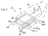
図2は、本発明の一実施形態によるフェルール12を含む構成部品の組立体を有する、光ファイバコネクタ10の斜視図である。コネクタ10は、フェルールハウジング14(点線で示す)、ケーブルブーツ16(点線で示す)、及び位置合わせガイドピン18を更に含む。図2は、光ファイバコネクタ10の簡略図である。本発明に従って構成されたフェルール12以外に、光ファイバ組立体10のその他の部品は、図1に示す光ファイバ組立体内の部品を更に含んでよい(即ち本発明によるフェルールは、US Conec社が提案するようなMTO/MPO光ファイバコネクタにおいて下位互換として使用できるように作製してよい)。図3、4は、図面から削除されたフェルールハウジング14及びケーブルブーツ16を備える光ファイバコネクタ10の様々な図である(これ以降、簡略化のために、フェルールハウジング14及びケーブルブーツを図面から削除して、更なる実施形態について議論及び例示する)。
FIG. 2 is a perspective view of an
図示した実施形態では、フェルール12は第1のフェルール半体12a及び第2のフェルール半体12bを含む。また図3を参照すると、各フェルール半体(12a、12b)は、概ね矩形のプレート構造を有する。フェルール半体12bは開放構造を有し、この開放構造はその上に、光ファイバケーブル22の光ファイバ20を収容するために平面状に精密に形成された開口溝24の列を有する(リボン型ファイバケーブルを図示したが、本発明の範囲及び精神を逸脱しない限りにおいて、リボンファイバケーブルの代わりに、光ファイバを束にして円形ファイバケーブルの形態としてもよいことを理解されたい)。2つのフェルール半体12a、12bは、フェルール半体12aがフェルール半体12bの溝24を被覆するように、嵌合構成で重ねられる。図示した実施形態では、12本の光ファイバ20を外被27内に保持し、光リボンファイバケーブル22を形成している。光ファイバケーブル22の終端光ファイバ20は、第2のフェルール半体12bの長手方向の溝24の列に受承される。溝24は、光ファイバ20の終端部分を、保護緩衝及び外被層が無くクラッドが露出した剥き出しの形態で受承する。(これ以降全ての議論では、光ファイバをフェルール溝に受承することに関して、光ファイバの終端部分は、保護緩衝及び外被層が無くクラッドが露出した剥き出しの形態であると理解される)。
In the illustrated embodiment, the
図4を参照すると、フェルール半体12a、12bの後尾部(26a、26b)は、頭部(36a、36b)よりも薄い。後尾部(26a、26b)の対面する側部によってこれらの間の窪み28が画定され、この窪み28は、フェルール半体12aとフェルール半体12bとを図2、4に示した構成で嵌合した際にこれらの間に外被27が受承されてクランプ留めされるように寸法決めされる。リボンファイバケーブル22の外被27を窪み28内に締り嵌めし、これにより外被(27a、27b)並びに外被27内のファイバ20上の保護緩衝及び外被層の厚みを収容する追加の空間を提供する。後尾部(26a、26b)により、ファイバケーブル22上に歪み緩和部が提供される。フェルール半体の少なくとも頭部(36a、36b)を、例えばレーザ溶接によって嵌合構成に維持する。あるいはフェルールは、フェルール半体(12a、12b)の頭部(36a、36b)を嵌合構成に維持するためのカラー又はスリーブ(図示せず)を更に備えてよい。
Referring to FIG. 4, the tails (26a, 26b) of the
溝の列の構成は、図3のフェルール12の端面図によりはっきりと示されている。図示した実施形態では、各溝は略平行の両側に略U字型の断面を有する。フェルール半体12a、12bの頭部36a、36bを嵌合して、第1のフェルール半体12aの頭部36aが第2のフェルール半体12bの頭部36b内の対向する溝開口を完全に被覆するようにする。
The configuration of the groove rows is clearly illustrated by the end view of the
溝24の深さは、光ファイバ20を完全に受承するように寸法決めされる。図示した実施形態では、溝の深さは少なくともD(例えば125マイクロメートル)、即ち保護緩衝及び外被層が無くクラッドが露出した光ファイバの剥き出しの部分の直径であり、本明細書全体を通してこの符号を用いる。溝の深さが略Dであることにより、第1のフェルール半体20aの頭部36aの平坦な底部と、対向する溝24とによって、光ファイバ20を精密に位置決めする空間が画定される。
The depth of the
少なくとも溝の一部に沿った壁間に画定される長手方向の開口の幅を、露出した光ファイバの直径より僅かに狭くすることによって、剥き出しのファイバ(保護緩衝及び外被層が無くクラッドが露出した剥き出しの部分)に対して密着嵌合(例えば1マイクロメートルの締り嵌め)を生成し、これにより光ファイバ20の端部部分を溝の長手方向の開口へと側方に挿入でき、また、光ファイバを溝24に密着させて固定できる。溝24及び長手方向の溝開口の幅は、ファイバ20が溝に対して動くことができるいずれの隙間も有さずファイバを固定するように成形及び寸法決めされる。溝24は(図示した)光ファイバの外形に適合するように、円形の底部、平坦な底部又はV溝を有してよい(これによりファイバと溝の壁との間に空間がもたらされる。この空間をエポキシ等の被包目的の追加の材料で充填して、特にフェルール端面の機械的研磨中に粒子を捕捉してしまうのを防止できる)。底部を円形にすると、ファイバとの接触領域が増大し、ファイバ内のより均一な弾性応力が得られるため、好適である。締め嵌めの溝の使用は、光ファイバの直径よりも大きくなるように許容誤差を設定された孔を有する図1に示す成形フェルールとは対照的である。従って、過大孔は従来技術の光ファイバの位置を管理できない。
By making the width of the longitudinal opening defined between the walls along at least a portion of the groove slightly narrower than the diameter of the exposed optical fiber, the exposed fiber (without the protective buffer and jacket layer is not clad). A close fit (eg, a 1 micron interference fit) to the exposed exposed portion), which allows the end portion of the
光ファイバ20を溝24内に完全に固定すると、光ファイバ20はフェルール半体(12a、12b)間に溝24aによって精密に位置決めされる。光ファイバ20の位置及び配向は、溝24の配置及び平行性により設定される。従って、例えば(位置合わせピン18を受承するためのメス構造を有する)対向する光ファイバコネクタ内のファイバに位置合わせするために、フェルール半体(12a、12b)における光ファイバ20の相対配置(例えば間隔)を、フェルール内に精密に維持する。相補的なフェルール半体はフェルール半体12bにファイバ20を位置決めするためのいずれの位置合わせ機能又は効果的な支持を提供しないので、確実かつ精密に光ファイバコネクタ内にファイバを位置決めするための相補的なフェルールは不要である。しかしながら、上側フェルール半体12aを設けると、これは光ファイバ20の偶発的な位置ずれを防止するための溝24のカバーとして機能する。
When the
本発明によると、位置合わせピン18をファイバ溝24に対して精密に配置するために、対応構造をフェルール12上に設ける。対応構造は、フェルール半体(12a、12b)の少なくとも一方に屈曲部を備える。一実施形態では、フェルール本体に設けられた1つ又は複数のスロットによって屈曲部を画定し、これにより、延在する片持ち構造の曲げを容易にする。スロットはフェルール本体の内側又は外側に設けてよい。
In accordance with the present invention, a corresponding structure is provided on the
図2〜3はフェルール12の外側に設けられたスロットを示している。特に、上側フェルール半体12aの各側部44付近には、長手方向の狭小スロット40をフェルール半体12aの上側に設けている。このスロット40は頭部36aから後尾部26aへと延在している。図3の端面図では、スロット40はフェルール半体12aの上側の外面に対して垂直である。スロット40は、側部44が第1のフェルール半体12aの基部45からカンチレバーリンク42を介して延在する(即ち側部44が基部45に対して片持ち構造となる)ように、上側フェルール半体12aの厚みを低減する。第1のフェルール半体12a内に側部44に対面する傾斜面49aを設け、第2のフェルール半体12b内に側部44に対面する傾斜面49bを設ける。側部44、傾斜面49a及び傾斜面49bにより、位置合わせピン18を光ファイバ20に対して精密に配置するための空間48が画定される(即ち3点接触をもたらす)。空間48に位置合わせピン18を挿入すると、カンチレバーリンク42は、側部44が基部45から離れて僅かに外側に変位できるように弾性変形する(屈曲する)。これにより内向きのバイアスを与え、フェルール半体の傾斜面に対して位置合わせピン18をクランプ留めする。
2 to 3 show slots provided outside the
傾斜面49a、49bをファイバ溝24に最も近接させると、これらの傾斜面は精密に形成できる本質的な基準面となり、片持ち側部44は上記基準面に影響を及ぼすことなく、ある程度の柔軟性をもって動作できる。本発明の別の態様では、上述の実施形態のファイバ溝は、打抜き加工や押出加工等の高スループット処理により精密形成される。フェルール部品(即ちフェルール半体12a、12b)の表面構造は、このような高スループット処理を用いた形成を可能とする。精密打抜き加工処理及び装置は、本発明の譲受人に譲渡された米国特許第7343770号明細書に開示されている。この特許はその全体が本明細書中に記載されているかのように、参照によってその全体が本明細書に援用される。上記に開示された処理及び打抜き加工装置を、本発明のフェルールを精密打抜き加工するために適合してよい。
When the inclined surfaces 49a and 49b are closest to the
一実施形態では、フェルール本体を金属材料で作製する。この金属材料は良好な熱寸法安定性を有するように(例えばアンバーを)選択してよい。 In one embodiment, the ferrule body is made of a metallic material. This metal material may be selected (eg, amber) to have good thermal dimensional stability.
本発明の別の実施形態では、第2のフェルール半体12bは、エポキシ又は相補的な精密部品を用いずに光ファイバを確実に保持できる精密溝クランプ留め用特徴部分がその上に形成された開放構造を有する。図5は第2のフェルール半体12bの頭部36bの溝24の部分を示す。
In another embodiment of the invention, the
溝24bは、ファイバ20(保護緩衝及び外被層が無くクラッドが露出した剥き出しの部分)をクランプ留めする開口により、例えば締り嵌め(又は押し合わせ)によってファイバ20を確実に固定するよう構成される。この締り嵌めにより、ファイバ20は所定の位置に確実にクランプ留めされ、結果としてファイバの位置及び配向は溝24の配置及び平行性により設定される。締り嵌めの使用は、光ファイバの直径よりも大きくなるように許容誤差を設定された孔を有する図1に示す成形フェルールとは対照的である。従って、過大孔は光ファイバの位置を管理できない。
The groove 24b is configured to securely fix the
図5に示す実施形態では、溝24の長手方向の開口23の幅Wを、光ファイバ20の直径よりも僅かに狭く作製している。特に、開口23は、長手方向の開口23の対向する長手方向端部に形成されたリップ25により画定される。長手方向の開口23の幅Wは僅かに小さ過ぎ、これにより、光ファイバの終端部分を溝の長手方向の開口23内に挿入して締り嵌めできる。締め代の大きさは、溝に対するファイバの荷重がリップにおける弾性変形又は微細な塑性変形のみをもたらすよう製造プロセスにより設定できる。溝は塑性変形すべきではない;塑性変形すると、ファイバ配置の正確性に影響を及ぼす。
In the embodiment shown in FIG. 5, the width W of the
具体的には、ファイバ20をフェルール12bの頭部36bに取り付けるため、ファイバ20の終端部分を、長手方向の開口23を介して縦長方向に(即ち溝の軸方向ではない方向に)溝24に押圧してスナップ嵌合させ、ファイバ20の先端を頭部36bの端面から僅かに突出させる。更に、長手方向の開口23の幅W及び溝24を、ファイバの端面が溝に対して軸方向及び平行移動できるようないずれの隙間を設けることなく、光ファイバ20を溝24にぴったりと固定するように寸法決め及び成形し、2つの隣接するファイバの端面間の光結合のための厳密な許容誤差を保証する。剥き出しのファイバ部分を、ファイバ20と溝24との間の嵌合表面に沿って締め代を有する溝に固定するためのエポキシは不要である。
Specifically, in order to attach the
図5に示す実施形態は、ファイバ20の本体に概ね一致する溝24の断面形状を示す。ファイバ20は、ファイバ20の上部を溝24の底部及びその他の部位に対して押圧するリップ25により、溝24内に確実に「クランプ留め」される。図示した実施形態では、ファイバ20の壁は、開口23付近を除いて溝24の全体の壁に対して押圧されている状態で示されている。これにより、略均一な押圧がファイバの略全体の周囲にもたらされるため、ファイバ20を介して伝送される光信号に対して、応力によって誘発されるファイバ又はコアの屈折率の変化がもたらす影響は比較的小さい。しかしながら、ファイバ20を溝24内に確実に固定するのに十分な締め嵌めを提供できる異なる断面を有するようにフェルールの溝を構成することもまた、十分に本発明の範囲及び精神の範疇である。例えば、溝は平坦な又は湾曲した底部、湾曲した側壁、又は上記平坦な底部(例えばV底部)に対して垂直若しくは僅かに外向きの平坦な側壁と、溝の長手方向の開口を画定するための内向き配向のリップとを有してよい。このような溝の構成は、湾曲したファイバ壁と平坦な又は湾曲した溝の側壁との間に一定の空間をもたらすが、リップ25及び/又はファイバに対する溝の垂直壁によるクランプ留め作用は、溝内でのファイバの動作を許容するいずれの隙間ももたらさない。この空の空間を、エポキシ等の被包目的の追加の材料で充填して、特にフェルール端面の機械的研磨中に粒子を捕捉してしまうのを防止できる。
The embodiment shown in FIG. 5 shows a cross-sectional shape of the
ファイバ20を溝24内に完全に固定すると、リップ25等の溝のプロファイル及び溝の底部は溝内のファイバ20の配置を規定し、ファイバ20は溝によってフェルール内に精密に位置決めされる。従って、例えば(位置合わせピン18を受承するためのメス構造を有する)対向する光ファイバコネクタ内のファイバに位置合わせするために、フェルール半体12bにおける光ファイバ20の相対配置(例えば間隔)を、フェルール内に精密に維持する。
When
非限定的な一例として、一実施形態では、コバール(54%のFe、29%のNi、17%のCo)材料製のフェルール内の、直径125マイクロメートルのシリカ製光ファイバ20bについて、溝24bの長さは1〜3mm、溝24bの直径又は幅(例えば最大横径D)は0.124mm、長手方向の開口23の幅Wは105マイクロメートルである。溝23の側壁は開口23に向かってファイバ20bの垂直接線に対して約5〜20度の角度θで内向きに傾斜している。設けられた締め代は約1マイクロメートルであり、これはシリカ及びコバール材料に適している。シリカガラスは圧迫に対して極めて高い強度を有するので、締め嵌めによる高い接触圧に耐えることができる。
As a non-limiting example, in one embodiment, a groove 24b for a 125 micrometer diameter silica optical fiber 20b in a ferrule made of Kovar (54% Fe, 29% Ni, 17% Co) material. Is 1 to 3 mm, the diameter or width (for example, maximum lateral diameter D) of the groove 24b is 0.124 mm, and the width W of the
図5による溝クランプ留め構造を有するフェルールについて、ファイバを光ファイバコネクタ内に確実かつ精密に位置決めするための相補的なフェルールは不要である。しかしながら、フェルール半体12b内にファイバ20を位置決めするためのいずれの位置合わせ機能又は効果的な支持を相補的なフェルール半体が提供せず、またその逆も真である場合でも、上記溝クランプ留め構造をそれぞれ有する2つのフェルール半体12a、12bを設けることにより、フェルール半体12a、12bは、高いファイバ密度を収容するフェルール12を形成する。
For the ferrule having the groove clamping structure according to FIG. 5, a complementary ferrule for positioning the fiber reliably and precisely in the optical fiber connector is not necessary. However, even if the complementary ferrule half does not provide any alignment function or effective support for positioning the
以上から、図1に示すコネクタ等の従来技術において実施されていたプラスチックフェルールブロックの貫通孔の形成に比べて、チャネル又は溝はより簡単かつ精密に形成できることがわかる。一実施形態では、最初に溝を(例えば精密打抜き加工により)形成し、続いてフェルール本体の上面を例えば打抜き加工又は押抜き加工することにより2つの対向する開口端部の材料を溝の開口内へと押し込んでリップを形成するか、又はレーザ加工により開口の角の材料を溶融させて溝の開口内へと流し込んでリップを形成することにより、溝の開口を狭める。別の実施形態では、クランプ留め用溝を押出加工により精密形成してよい。図5に示すクランプ留め用溝の高スループット形成についての更なる情報は、本発明の譲受人に譲渡された2012年4月5日出願の米国特許出願第13/440970号明細書に開示されている。この出願はその全体が本明細書中で述べられているかのように、参照によりその全体が本明細書に援用される。 From the above, it can be seen that the channel or the groove can be formed more easily and precisely than the formation of the through hole of the plastic ferrule block which has been implemented in the prior art such as the connector shown in FIG. In one embodiment, the groove is first formed (e.g., by precision stamping) and then the top surface of the ferrule body is e.g. The opening of the groove is narrowed by forming a lip by pushing into the groove or by melting the material at the corners of the opening by laser processing and pouring it into the opening of the groove to form a lip. In another embodiment, the clamping groove may be precision formed by extrusion. More information about the high-throughput formation of the clamping groove shown in FIG. 5 is disclosed in US patent application Ser. No. 13/440970 filed Apr. 5, 2012, assigned to the assignee of the present invention. Yes. This application is hereby incorporated by reference in its entirety as if set forth in its entirety herein.
図2〜4の実施形態では、対応構造は各位置合わせピン18について、位置合わせピンとフェルール半体との間に3点接触(断面図参照)をもたらす1つの屈曲部を含む。図6、7は、対応構造が、位置合わせピンとフェルール半体との間に4点接触をもたらす2つの屈曲部を有する代替実施形態を示す。本実施形態における光ファイバコネクタ110の全体構造は、フェルールを除いて図2〜4の実施形態の光ファイバコネクタ10の構造と同様である。光ファイバコネクタ110は、2つのフェルール半体112a、112bを含むフェルール112、フェルールハウジング及びケーブルブーツ(図2に示したものと同様であるが、簡潔にするために削除している)を備える。フェルール半体(112a、112b)は、光ファイバ20を支持するための溝24を備える。ファイバ溝24の全体構造は図2(又は図5の代替実施形態)の溝の構造と同様である。
In the embodiment of FIGS. 2-4, the corresponding structure includes, for each
先行の実施形態と比較すると、第2の(下側)フェルール112bの外側に追加のスロットが設けられている。具体的には、第1のフェルール半体112aの各側部144aの付近に、フェルール半体112aの頭部136aから後尾部126aへと延在する長手方向の狭小スロット140aを、フェルール半体112aの上部外側に設ける。更に、第2のフェルール半体112bの各側部144bの付近に、フェルール半体112bの頭部136bから後尾部126bへと延在する長手方向の狭小スロット140bを、フェルール半体112bの上部外側に設ける。図7の端面図では、スロット140a、140bはフェルール半体112a、112bの外面に垂直である。スロット(140a、140b)に関する設計考慮点及び目的は、先行の実施形態におけるスロット40と同様である。特に、スロット(140a、140b)は、側部(144a、144b)が第1及び第2のフェルール半体(112a、112b)の基部(145a、145b)からカンチレバーリンク(142a、142b)を介して延在する(即ち側部(144a、144b)が基部(145a、145b)に対して片持ち構造となる)ように、上側及び第2のフェルール半体(112a、112b)の厚みを低減する。本実施形態では、傾斜面149a、150aは、第1のフェルール半体112aのスロット140aと側部144aとの間に設けられたV溝160により画定され、傾斜面149b及び150bは、第2のフェルール半体112bのスロット140bと側部144bとの間に設けられたV溝162により画定される。このV溝(160、162)は、フェルール半体(112a、112b)を通って頭部(136a、136b)から後尾部(126a、126b)へと延在する。各位置合わせピン領域では、傾斜面149a、149b、150a、150bにより、位置合わせピン18を光ファイバ20に対して精密に配置するための空間148が画定される(例えば4点接触となる)。空間148に位置合わせピン18を挿入すると、カンチレバーリンク(142a、142b)は、側部(144a、144b)が基部(145a、145b)から離れて僅かに外側に変位できるように弾性変形する。これにより内向きのバイアスを与え、フェルール半体(112a、112b)の傾斜面間で位置合わせピン18をクランプ留めする。
Compared to the previous embodiment, an additional slot is provided outside the second (lower)
傾斜面149a、149bをファイバ溝24に最も近接させると、これらの傾斜面は精密に形成可能な本質的な基準面となり、片持ち側部(144a、144b)は上記基準面に影響を及ぼすことなく、ある程度の柔軟性をもって動作できる。
When the inclined surfaces 149a and 149b are closest to the
図2〜7の先行の2つの実施形態では、フェルール半体の外面にスロットを設けている。その代替として図8、9を参照すると、スロットをフェルール半体の内面に設けてもよい。図8、9は、対応構造がフェルール半体(212a、212b)の内面上のスロット(240a、240b)によって画定される2つの屈曲部を有し、これにより位置合わせピンとフェルール半体との間に4点接触が提供される、光ファイバコネクタ210の実施形態を示す。本実施形態における光ファイバコネクタ210の全体構造は、フェルールを除いて図6、7の光ファイバコネクタ110の構造と同様である。光ファイバコネクタ210は、2つのフェルール半体212a、212bを含むフェルール212、フェルールハウジング及びケーブルブーツ(図2に示したものと同様であるが、簡潔にするために削除している)を備える。フェルール半体(212a、212b)は、光ファイバ20を支持するための溝24を備える。ファイバ溝24の全体構造は図2(又は図5の代替実施形態)の溝の構造と同様である。
In the two preceding embodiments of FIGS. 2-7, a slot is provided on the outer surface of the ferrule half. As an alternative, referring to FIGS. 8 and 9, slots may be provided on the inner surface of the ferrule half. FIGS. 8 and 9 have two bends in which the corresponding structure is defined by slots (240a, 240b) on the inner surface of the ferrule halves (212a, 212b) so that the alignment pin and the ferrule halves are in between. FIG. 4 illustrates an embodiment of a
図6、7の先行の実施形態と比較すると、第1及び第2のフェルール(212a、212b)の内面、即ち対面する表面にスロットが設けられている。具体的には、第1のフェルール半体212aの各側部244aの付近に、フェルール半体212aの頭部236aから後尾部226aへと延在する長手方向の狭小スロット240aを、フェルール半体212aの上部内側に設ける。更に、第2のフェルール半体212bの各側部244bの付近に、フェルール半体212bの頭部236bから後尾部226bへと延在する長手方向の狭小スロット240bを、下側フェルール半体212bの上部内側に設ける。図9の端面図では、スロット240a、240bはフェルール半体212a、212bの内面に垂直である。先行の実施形態における傾斜面149a、149b、150a、150bと同様に、ピンクランプ留め傾斜面249a、249b、250a、250bは、フェルール半体(212a、212b)上に設けられたV溝(260a、260b)により画定される。内側スロット(240a、240b)は、V溝(260a、260b)の底部からフェルール半体(212a、212b)へと延在する。スロット(240a、240b)に関する設計考慮点及び目的は、先行の実施形態におけるスロット40及び140と同様である。特に、スロット(240a、240b)は、側部(244a、244b)が第1及び第2のフェルール半体(212a、212b)の基部(245a、245b)からカンチレバーリンク(242a、242b)を介して延在する(即ち側部(244a、244b)が基部(245a、245b)に対して片持ち構造となる)ように、上側及び第2のフェルール半体(212a、212b)の厚みを低減する。各位置合わせピン領域では、傾斜面249a、249b、250a、250bにより、位置合わせピン18を光ファイバ20に対して精密に配置するための空間248が画定される(例えば4点接触となる)。空間248に位置合わせピン18を挿入すると、カンチレバーリンク(242a、242b)は、側部(244a、244b)が基部(245a、245b)から離れて僅かに外側に変位できるように弾性変形する。これにより内向きのバイアスを与え、フェルール半体(212a、212b)の傾斜面間で位置合わせピン18をクランプ留めする。
Compared with the previous embodiment of FIGS. 6 and 7, slots are provided on the inner surfaces of the first and second ferrules (212 a, 212 b), that is, the facing surfaces. Specifically, in the vicinity of each
図10、11は、対応構造が図8及び9の実施形態の変形例である、光ファイバコネクタの代替実施形態である。本実施形態における光ファイバコネクタ310の全体構造は、フェルールを除いて図8、9の実施形態の光ファイバコネクタ210の構造と同様である。光ファイバコネクタ310は、2つのフェルール半体312a、312bを含むフェルール312、フェルールハウジング及びケーブルブーツ(図2に示したものと同様であるが、簡潔にするために削除している)を備える。フェルール半体(312a、312b)は、光ファイバ20を支持するための溝24を備える。ファイバ溝24の全体構造は図9の溝の構造と同様である。図9と比較すると、図11の実施形態における違いは、図9ではフェルール半体の内面に対して垂直に設けたのに対し、図11の端面図に示すように、内部スロット340a、340bをフェルール半体312a、312bの内面に対して一定の角度で設ける点にある。
10 and 11 are alternative embodiments of the optical fiber connector in which the corresponding structure is a modification of the embodiment of FIGS. 8 and 9. The overall structure of the
図12、13は、光ファイバコネクタ410の代替実施形態である。本実施形態では、スロットがフェルール半体の屈曲部を画定する代わりに、フェルール半体の空間の上の片持ち梁により屈曲部を画定する。本実施形態における光ファイバコネクタ410の全体構造は、フェルールを除いて図2〜4の実施形態の光ファイバコネクタ10の構造と同様である。光ファイバコネクタ410は、2つのフェルール半体412a、412bを含むフェルール412、フェルールハウジング及びケーブルブーツ(図2に示したものと同様であるが、簡潔にするために削除している)を備える。フェルール半体412は、光ファイバ20を支持するための溝24を備える。ファイバ溝24の全体構造は図3の溝の構造と同様である。
12 and 13 are alternative embodiments of the
本実施形態では、下側(第2の)フェルール412bに設けた空間440の上に渡された片持ち梁442を備える屈曲部が対応構造を画定する。V溝460により画定されるピンクランプ留め用傾斜面249を、第1のフェルール半体412a上に設ける。第2のフェルール半体412b上に矩形底溝又は矩形のチャネル462を設ける。V溝460及び矩形底溝462は、フェルール半体(412a、412b)を通って頭部(436a、436b)から後尾部(426a、426b)へと延在する。各位置合わせピン領域では、傾斜面449及び屈曲表面450により、位置合わせピン18を光ファイバ20に対して精密に配置するための空間448が画定される。梁442の屈曲表面450及び傾斜面449は、位置合わせピン18の3点接触を画定する。V溝460は、位置合わせピンの精密な基準配置を提供する。梁442は、下の空間440に向かって弾性変形できる(僅かに屈曲できる)。空間448に位置合わせピン18を挿入すると、渡し梁442は僅かに下側に空間440に向かって弾性変形する(屈曲する)。これにより上向きのバイアスを与え、フェルール半体のV溝460の傾斜面に対して位置合わせピン18をクランプ留めする。
In the present embodiment, the bent portion including the
図13に示す実施形態では、位置合わせピン18用の対応構造は、一方のフェルール半体上に設けたV溝ともう一方のフェルール半体上に設けた矩形底溝との組み合わせにより画定される。V溝460を(例えば精密打抜き加工により)精密に形成でき、矩形底溝462の壁を精密に形成する必要なく矩形底溝462の深さを精密に形成できる。矩形溝462の横の長さの変化はピンの位置決めに影響しない。頭部436aと頭部436bとを嵌合すると、V溝460の精密に画定された傾斜面459と矩形底溝462の屈曲表面450の精密深さとの組み合わせにより、位置合わせピン18が正確かつ精密に位置決めされる。
In the embodiment shown in FIG. 13, the corresponding structure for the
第1のフェルール半体412aはV溝460を備え、第2のフェルール半体412bは片持ち梁(矩形チャネル462及び空間440)を備えるが、V溝及び片持ち梁をそれぞれのフェルール半体に設けること(図示せず)もまた、十分に本発明の範囲及び精神の範疇である。代替実施形態(図示せず)では、フェルール半体をより対称性を持つよう作製してよい。一方のフェルール半体にのみ光ファイバ用の溝を設けるのではなく、各フェルール半体が光ファイバ支持用の半円形状の溝を有する頭部を備えるよう構成してよい。位置合わせピンをクランプ留めするための対応構造も対称性を持つように作製してよい。対称性を持つフェルール半体の場合、同一構成部品の在庫管理が容易である。しかしながら、光ファイバ20を支持するよう嵌合できる限りにおいて、フェルール半体は同一である必要はない。
The first ferrule half 412a includes a V-
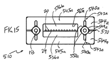
図14〜18は光ファイバコネクタ510の別の実施形態である。本実施形態では、フェルール590は、光ファイバ20を支持するための溝24を有するフェルールインサート512、並びに上記フェルールインサート512及び位置合わせピンを支持するフェルールフレーム552を備える。図示した実施形態では、フェルールインサート512は、(フェルール12a、12b、又は412a、412b等のように)、ファイバ用溝を有さない下側フェルールプレート512a、及び画定された光ファイバ用の溝を有する上側フェルールプレート512bを備える。本実施形態のフェルールインサート512は、フェルールインサート512が光ファイバ20及びファイバケーブル20を前述の実施形態と同様の様式でクランプ留めするよう構成されている点で、前述の実施形態のフェルールと類似している。フェルールフレーム552はフレーム前部555a及びフレーム後部555bを含む。図示した実施形態では、フレーム部555a、555bは同様の構造を共有している。フェルールプレート(512a、512b)の頭部(536a、536b)を嵌合してフレーム前部555aの開口565aへと挿入し、フェルールプレート(512a、512b)の後尾部(526a、526b)をフレーム後部555bへと挿入することにより、フェルール構造を完成させる。
14-18 are another embodiment of an
位置合わせピン18を支持するピンクランプ留め用対応構造をフェルールフレーム552上に設ける。具体的には、フレーム前部555a及びフレーム後部555bに屈曲部を設ける。図15を参照すると、本実施形態ではフレーム部(555a、555b)がそれぞれ単一の1つの部品であり、かつファイバ溝を備えていないこと以外は、対応構造は図9に示すフェルール212上の内部にスロットを付けた対応構造に類似している。結果として対応構造は、スリット開口570を有するC字型構造に近いものとなる。前述の実施形態の傾斜面249a、249b、250a及び250bと同様に、ピンクランプ留め用傾斜面549a、549b、550a、550bを、フレーム部(555a、555b)上に設けたV溝(560a、560b)により画定する。内部スロット(540a、540b)は、V溝(560a、560b)の底部からフレーム部(555、556)へと延在する。スロット(540a、540b)に関する設計考慮点及び目的は、先行の実施形態におけるフェルール用のスロット40、140及び240と同様である。特に、スロット(540a、540b)は、側部(544a、544b)がフレーム部(555a、555b)の基部(545a、545b)からカンチレバーリンク(542a、542b)を介して延在する(即ち側部(544a、544b)が基部(545a、545b)に対して片持ち構造となる)ように、フレーム部(555a、555b)の厚みを低減する。各位置合わせピン領域では、傾斜面(549a及び550a、並びに549b及び550b)により、位置合わせピン18を光ファイバ20に対して精密に配置するための空間(548a、548b)が画定される(例えば4点接触となる)。位置合わせピンは、フレーム前部及び後部(555a、555b)上に設けた対応構造へと挿入される。空間(548a、548b)に位置合わせピン18を挿入すると、カンチレバーリンク(542a、542b)は、側部(544a、544b)が基部(545a、545b)から離れて僅かに外側に変位できるように弾性変形する。これにより内向きのバイアスを与え、フレーム部(555a、555b)の傾斜面間に位置合わせピン18をクランプ留めする。図示した実施形態では、フェルールプレート(512a、512b)は、その上に溝(576a、576b)を設けた、各側面から延在するフランジ(575a、575b)をそれぞれ備える。フェルールプレート(512a、512b)を嵌合すると、溝(576a、576b)は位置合わせピンをフレーム前部555aからフレーム後部555bへと案内するためのガイド孔を形成する。
A corresponding structure for pin clamping that supports the
図19及び20は、フェルールフレームが、フェルールインサートを支持する単一の一体構造であってよい、代替実施形態である。図19の実施形態では、光ファイバコネクタ610は、フレーム652及びフェルールプレート(612a、612b)を含むフェルールインサート612を備えるフェルール690を含む。上記フェルールプレートは、開口665a、665bを通してフレーム前部655a及びフレーム後部655bに挿入できる概ね平坦な筒状プロファイルを形成する。本実施形態では、フレーム652は、ブリッジ680により接続されたフレーム前部及び後部(655a、655b)を含む一体部品である。ブリッジ680は、フレーム前部及び後部の間にフレーム652の全長幅に亘って延在してよい。
19 and 20 are alternative embodiments in which the ferrule frame may be a single unitary structure that supports the ferrule insert. In the embodiment of FIG. 19, the fiber optic connector 610 includes a
図20の実施形態では、光ファイバコネクタ610’は、フェルールフレーム652’
及びフェルールプレート(612a、612b)を含む同様のフェルールインサート612を備える、フェルール690’を備える。フェルールプレートは、開口665を通ってフレーム652’に挿入できる概ね平坦な筒状プロファイルを形成する。先行の実施形態とは異なり、フェルールフレーム652’全体が1つの部分となっている。フレーム652’の前方から後方へと延在する、同様の対応構造を設ける。フェルールフレーム652’は、先行の実施形態と関連して開示されたものと同様の対応構造を備える。
In the embodiment of FIG. 20, the fiber optic connector 610 ′ is a
And a
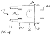
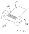
図21〜25は、光ファイバコネクタ710の別の実施形態を示す。この実施形態は、フェルールフレーム752及びその周囲に光ファイバ溝24を備えたオフセット構造(ドッグボーン形状に類似している)を含むフェルールインサート712を備える、フェルール790を備える。図25を参照すると、スタブ777はフェルールインサート712の中央からフレーム基部755に向かって延在している。図示した実施形態では、ファイバ溝(24a、24b)を、2本のファイバケーブル(22a、22b)の光ファイバ(20a、20b)を収容できるオフセット構造の周囲の対面する表面に設ける。
FIGS. 21-25 illustrate another embodiment of a
図23を参照すると、フェルールインサート712の2つの端部に、位置合わせピン18を支持する対応構造が設けられている。特に、対応構造は、基部745から位置合わせピン18の周囲に延在するフィンガ744を有するC字型の屈曲部を備える。フィンガ744は、位置合わせピンの挿入の際に屈曲リンク742において屈曲できる。本実施形態では、対応構造は、対応構造内に画定される部分円形開口798によってもたらされる、位置合わせピンとの原則的に複数の接触点をもたらす。
Referring to FIG. 23, a corresponding structure for supporting the
フェルールフレーム752は、フェルールフレーム752の基部755から延在する平坦なカバー部780を有する。カバー部780は、フェルールインサート712上の少なくともファイバ溝(724a、724b)を被覆する。カバー部780及び溝(724a、724b)は、図3との関連で議論したフェルール12のフェルール基部45及び溝24と類似している。溝(24a、24b)を用いた光ファイバ(22a、22b)の精密な支持について、上述と同様の考察をここで本実施形態に適用する。特に、溝(724a、724b)は、図3の実施形態のフェルール半体12bの表面上の溝24又は図5の実施形態の溝と同様の構造をとることができる。
図22を参照すると、フェルールインサート712をフェルールフレーム752に組み付けるために、フレーム基部755のカバー部780間で画定される空間728を通して、光ファイバ(22a、22b)の外被(27a、27b)が挿入されている。剥き出しの光ファイバ(20a、20b)をフェルールインサート712上の溝(24a、24b)へと挿入する。フェルールインサート712背後のスタブ777によってファイバ外被(27a、27b)を支持し、2つのカバー部780間で画定される空間728へとフェルールインサート712を挿入して、図21のフェルール構造を完成させる。
Referring to FIG. 22, for assembling the
図26、27は、図25に示すフェルールインサートと比較したフェルールインサート用の対応構造の変形例である。図26では、本実施形態においてはフレームインサート712’が一体部品構造であり、フェルールインサート712’の周囲の表面上にファイバ溝を備える点を除いて、対応構造744’は図3に示すフェルール12上の対応構造と同様である。結果として得られる対応構造744’は、スリット開口770を有するC字型構造に近いものとなる。同様の設計考慮点及び目標を本実施形態に適用できる。本実施形態は、開口799内の位置合わせピン上の3点接触(2つの傾斜面及びフィンガ742’の内面)を本質的に提供する。
26 and 27 are modifications of the corresponding structure for ferrule inserts compared to the ferrule insert shown in FIG. In FIG. 26, in this embodiment, the
図27では、図25の円形溝の代わりにV溝760が設けられる点、及びフィンガ742’’の屈曲を容易にするスリット770と共に小スロット795が直線で設けられる点を除いて、対応構造744’’は図25に示す構造と類似している。本実施形態は、開口797における4点接触を提供する。
In FIG. 27, the corresponding
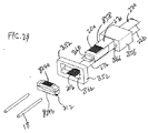
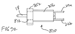
別の実施形態では、フェルールフレームはフェルールインサートの周囲を取り囲む。図28〜32は、本発明の更なる実施形態による高密度光ファイバコネクタである。本実施形態では、光ファイバコネクタ810は、単一部品フェルール812、フレーム852、フェルールハウジング及びケーブルブーツ(図2に示したものと同様であるが、簡潔にするために削除している)を含む。本実施形態では、リボンケーブル(22a、22b)の終端光ファイバ(20a、20b)を2つの平行面に2列に整列させるよう、フェルール812を構成する。光ファイバ20a、20bは異なる光ファイバケーブル22a、22bから交互に延在する。図30に示すように、第1のファイバケーブル22aの終端光ファイバ20aをフェルール812の周囲の上面上に設けられた溝824a上に支持し、第2のファイバケーブル22bの終端光ファイバ20bをフェルール812の周囲の底面上に設けられた溝824b上に支持する。溝(824a、824b)は、図3の実施形態のフェルール半体12bの表面上の溝24、又は図5の実施形態の溝と同様の構造をとる。
In another embodiment, the ferrule frame surrounds the periphery of the ferrule insert. 28-32 are high density optical fiber connectors according to further embodiments of the present invention. In this embodiment, the
各溝(824a、824b)は、対応する光ファイバ(20a、20b)を完全に受承する。フレーム852は、フェルール812をフレーム852へと挿入する際に溝(824a、824b)に対面する内側平坦部(850a、850b)を有する。平坦部(850a、850b)は溝(824a、824b)を完全に被覆する。光ファイバ(20a、20b)を溝(824a、824b)内に完全に固定すると、光ファイバ(20a、20b)は溝(824a、824b)によってフェルール半体(12a、12b)内に精密に位置決めされる。光ファイバ(20a、20b)の位置及び配向は、溝(824a、824b)の配置及び平行性により設定される。従って、例えば(位置合わせピン18を受承するためのメス構造を有する)対向する光ファイバコネクタ内のファイバに位置合わせするために、フェルール半体(12a、12b)における光ファイバ(20a、20b)の相対配置(例えば間隔)を、フェルール内に精密に維持する。ファイバを光ファイバコネクタ810内に確実かつ精密に位置決めするための相補的なフェルール又はフレームは不要である。フレーム852はフェルール812にファイバ(20a、20b)を正確に位置決めするためのいずれの位置合わせ機能又は効果的な支持を提供しないが、フレーム852は光ファイバの偶発的な変位を防止するために溝(824a、824b)を被覆するよう機能する。
Each groove (824a, 824b) fully receives the corresponding optical fiber (20a, 20b). The
開口を通してファイバケーブル(22a、22b)の外被(27a、27b)を歪み緩和アンカー856へと挿入し、延長部858上に支持する。延長部858は、フェルール812の中心開口862へと延在するスタブ860を有する。フェルール812に設けられた孔864へと位置合わせピン18を挿入し、歪み緩和アンカー856に設けられた孔866へと延在する。孔864は、フェルール812の各端部に設けられたスプリット868により画定される。スプリットを画定する少なくとも1つのプロング870の材料厚さを薄くすることにより、プロング870の屈曲を容易にする。これにより、別の相補的な光ファイバコネクタに対する位置合わせのために位置合わせピンを正確かつ精密に配置するために位置合わせピンをクランプ留めする対応構造を画定する屈曲部を形成する。
The jacket (27a, 27b) of the fiber cable (22a, 22b) is inserted through the opening into the
図示した実施形態では、フレーム852がフェルール812の周囲を取り囲んでいるが、フェルール812の周囲を取り囲まずに溝(824a、824b)を被覆するようにフレームを構成してよい。フレームを、完全なリング(図示せず)の代わりに例えば図30の端面図の部分的なリング(例えばC字型)として構成してよい。あるいは、フレーム852を除外し、フェルール812の上側表面及び下側表面上の溝(824a、824b)を被覆する2つの延在する平坦フィンガ(図示せず)と併せてアンカー856を設けてよい。
In the illustrated embodiment, the
先行の実施形態の場合、フェルール812、フレーム852及び/又はアンカー856を、金属で作製し、高スループットの打抜き加工及び/又は押出加工処理により形成してよい。
In the previous embodiment, the
高密度フェルール構造は、本明細書と同時に出願された別の米国特許出願(代理人整理番号1125/240)の主題である。上記出願はその全体が本明細書中に記載されているかのように、参照によってその全体が本明細書に援用される。 The high density ferrule structure is the subject of another US patent application (Attorney Docket No. 1125/240) filed concurrently with this specification. The above application is hereby incorporated by reference in its entirety as if set forth in its entirety herein.
上述の実施形態について、フェルールを金属材料で作製してよい。この金属材料は、高剛性(例えばステンレス鋼)、化学不活性(例えばチタン)、高温安定性(例えばニッケル合金)、低熱膨張率(例えばアンバ)を有するよう、又は他の材料の熱膨張率と適合する(例えばガラスと適合するコバール)よう選択してよい。本発明の別の態様では、打抜き加工や押出加工等の高スループット処理により、独自のフェルールを精密に形成する。 For the above-described embodiment, the ferrule may be made of a metal material. This metal material has high rigidity (eg stainless steel), chemical inertness (eg titanium), high temperature stability (eg nickel alloy), low coefficient of thermal expansion (eg amber), or other materials It may be selected to be compatible (eg Kovar compatible with glass). In another aspect of the present invention, a unique ferrule is precisely formed by high-throughput processing such as punching or extrusion.
本発明によるフェルールは、従来技術の欠点の多くを克服する。対応クランプ留め用構造により、間隙を有さない孔へと位置合わせピンを挿入でき、これにより孔と位置合わせピンとの間のいずれの間隙を充填するためのエポキシが不要となる。フェルール内の溝とファイバと位置合わせピンとの間に、部品間の移動を引き起こし得るいずれの間隙を有さないことにより、位置合わせピン及びファイバを互いに対してより正確に配置できる。例えばフェルールが、指定された位置合わせの許容誤差に影響を与えることなく、比較的大きな寸法変化に適応できるため、環境条件が変化してもファイバとピンとの間隔をより良好に維持できる。従って、形成された光ファイバコネクタは、低挿入損失及び低反射損失をもたらす。またこのようなフェルール構造により、エポキシ被覆ファイバを孔に通す従来のフェルールと比較して、ファイバ終端部のフェルールへの取付けが容易になる。エポキシを使用しないことにより、光ファイバコネクタの信頼性は、エポキシ材料のいずれの劣化/クリープに影響されない。フェルールに適した材料を選択することで、光ファイバコネクタの性能の、熱の変化に対する感受性を低下させる。フェルールの開放構造は、例えば打抜き加工や押出加工などの安価で高スループット処理である大量生産プロセスを可能とする。 The ferrule according to the present invention overcomes many of the disadvantages of the prior art. The corresponding clamping structure allows the alignment pin to be inserted into a hole without a gap, thereby eliminating the need for epoxy to fill any gap between the hole and the alignment pin. By having no gap between the groove in the ferrule and the fiber and alignment pin that can cause movement between parts, the alignment pin and fiber can be more accurately positioned relative to each other. For example, the ferrule can be adapted to relatively large dimensional changes without affecting the specified alignment tolerances, so that the fiber-to-pin spacing can be better maintained even when environmental conditions change. Thus, the formed optical fiber connector provides low insertion loss and low reflection loss. In addition, such a ferrule structure facilitates attachment of the fiber end portion to the ferrule as compared with a conventional ferrule in which an epoxy-coated fiber is passed through a hole. By not using epoxy, the reliability of the fiber optic connector is not affected by any degradation / creep of the epoxy material. Selecting a suitable material for the ferrule reduces the sensitivity of the fiber optic connector performance to thermal changes. The open structure of the ferrule enables a low-cost and high-throughput mass production process such as punching or extrusion.
本発明を好適な実施形態を参照して図示し、説明してきたが、本発明の精神、範囲及び教示から逸脱することなく、様々な変更を施せることは当業者には理解されるであろう。従って、開示した発明は、単なる例示、及び添付の請求項に明記された範囲のみに限定されるものと考えるべきものではない。 While the invention has been illustrated and described with reference to preferred embodiments, workers skilled in the art will recognize that various modifications can be made without departing from the spirit, scope and teachings of the invention. . Accordingly, the disclosed invention is not to be considered as being limited to the scope specified in the exemplifications and appended claims.
1400、10、110、210、310、410、510、610’、710、810 光ファイバコネクタ
1402、12、112、212、312、412、590、690’、812 フェルール
1404、14 フェルールハウジング
1406、16 ケーブル外被、ブーツ
1408、18 位置合わせガイドピン
1410 ケーブル
1412、20 光ファイバ
12a、12b、112a、112b、212a、212b、312a、312b、412a、412b、512a、512b フェルール半体
22 光リボンファイバケーブル
23、565a、665、665a、665b、797、798、799、862 開口
24、24a、24b、724a、724b、824a、824b 溝
25 リップ
26a、26b、126a、126b、226a、226b、426a、426b、526a、526b 後尾部
27a、27b 外被
28 窪み
36a、36b、136a、136b、236a、236b、436a、436b、536a、536b 頭部
40、140a、140b、240a、240b、340a、340b、540a、540b スロット
42、142a、142b、242a、242b、542a、542b、(442)、742 カンチレバーリンク、(片持ち梁)、屈曲リンク
44、144a、144b、244a、244b、544a、544b、(744) 側部、(フィンガ)
45、145a、145b、245a、245b、545a、545b、745 基部
48、148、248、440、448、548a、548b、728 空間
49a、49b、149a、149b、150a、150b、249a、249b、250a、250b、449、549、550 傾斜面
450 屈曲表面
160、162、260a、260b、460、560a、560b、760 V溝
462 チャネル
512、612、712 フェルールインサート
512a、512b、612a、612b フェルールプレート
552、652’、752、852 フェルールフレーム、フレーム
555a、655a フレーム前部
555b、655b フレーム後部
570、770 スリット開口
575a、575b フランジ
755 フレーム基部
777、860 スタブ
780 カバー部
744’、744’’ 対応構造
795 小スロット
850a、850b 平坦部
856 アンカー
858 延長部
864、866 孔
868 スプリット
870 プロング
1400, 10, 110, 210, 310, 410, 510, 610 ′, 710, 810
45, 145a, 145b, 245a, 245b, 545a, 545b, 745
795 Small slot 850a, 850b
Claims (17)
位置合わせピンをクランプ留めするための対応構造を備え、
前記対応構造は、当該フェルール内に画定されたスロットにより画定される屈曲部を備え、
前記スロットが、当該フェルールの前記光ファイバが支持されている断面に対して垂直でない角度をなして、前記位置合わせピンに向かって延在しており、
前記スロットが、前記位置合わせピンに近い側の端部において開口で終端し、前記開口の両側の面が、前記位置合わせピンに直接接触する、
ことを特徴とするフェルール。 A ferrule for supporting an optical fiber in an optical fiber connector,
With a corresponding structure for clamping the alignment pin,
The corresponding structure comprises a bend defined by a slot defined in the ferrule;
The slot extends toward the alignment pin at an angle that is not perpendicular to a cross section of the ferrule on which the optical fiber is supported ;
The slot terminates in an opening at an end near the alignment pin, and both sides of the opening are in direct contact with the alignment pin;
Ferrule characterized by that.
前記フェルール半体の少なくとも一方が、前記光ファイバを支持するための少なくとも1つの光ファイバ溝を有することを特徴とする請求項1または2記載のフェルール。 The ferrule includes two opposing ferrule halves having opposing surfaces superimposed on each other;
The ferrule according to claim 1 or 2 , wherein at least one of the ferrule halves has at least one optical fiber groove for supporting the optical fiber.
前記光ファイバを支持するフェルールインサートと、A ferrule insert that supports the optical fiber;
前記フェルールインサートを支持するフェルールフレームであって、位置合わせピンをクランプ留めするための対応構造を有するフェルールフレームと、A ferrule frame for supporting the ferrule insert, the ferrule frame having a corresponding structure for clamping an alignment pin;
を含み、Including
前記対応構造は、前記フェルールフレーム内に画定されたスロットにより画定される屈曲部を備え、The corresponding structure comprises a bend defined by a slot defined in the ferrule frame;
前記スロットが、前記光ファイバが支持されている面に対して角度をなして、前記位置合わせピンに向かって延在しており、The slot extends toward the alignment pin at an angle to a surface on which the optical fiber is supported;
前記スロットが、前記位置合わせピンに近い側の端部において開口で終端し、前記開口の両側の面が、前記屈曲部によるバイアスによって前記位置合わせピンに直接接触する、The slot terminates in an opening at an end near the alignment pin, and surfaces on both sides of the opening are in direct contact with the alignment pin by a bias by the bent portion;
ことを特徴とするフェルール。Ferrule characterized by that.
前記フェルールプレートの少なくとも一方が、前記光ファイバを支持するための少なくとも1つの光ファイバ溝を有することを特徴とする請求項5記載のフェルール。 The ferrule insert includes two opposing ferrule plates having opposing surfaces superimposed on each other;
The ferrule according to claim 5, wherein at least one of the ferrule plates has at least one optical fiber groove for supporting the optical fiber.
Applications Claiming Priority (3)
| Application Number | Priority Date | Filing Date | Title |
|---|---|---|---|
| US201261620945P | 2012-04-05 | 2012-04-05 | |
| US61/620,945 | 2012-04-05 | ||
| PCT/US2012/059835 WO2013151583A1 (en) | 2012-04-05 | 2012-10-11 | Ferrule for optical fiber connector having a compliant structure for clamping alignment pins |
Publications (3)
| Publication Number | Publication Date |
|---|---|
| JP2015512531A JP2015512531A (en) | 2015-04-27 |
| JP2015512531A5 JP2015512531A5 (en) | 2015-12-03 |
| JP6334510B2 true JP6334510B2 (en) | 2018-05-30 |
Family
ID=47295127
Family Applications (2)
| Application Number | Title | Priority Date | Filing Date |
|---|---|---|---|
| JP2015504542A Active JP6404812B2 (en) | 2012-04-05 | 2012-10-11 | High density multi-fiber ferrule for optical fiber connector |
| JP2015504543A Active JP6334510B2 (en) | 2012-04-05 | 2012-10-11 | Ferrule for optical fiber connector with corresponding structure for clamping the alignment pin |
Family Applications Before (1)
| Application Number | Title | Priority Date | Filing Date |
|---|---|---|---|
| JP2015504542A Active JP6404812B2 (en) | 2012-04-05 | 2012-10-11 | High density multi-fiber ferrule for optical fiber connector |
Country Status (10)
| Country | Link |
|---|---|
| US (4) | US9507099B2 (en) |
| EP (2) | EP2834689A1 (en) |
| JP (2) | JP6404812B2 (en) |
| KR (2) | KR101989650B1 (en) |
| CN (2) | CN104335090B (en) |
| AU (2) | AU2012376220B2 (en) |
| CA (2) | CA2869318C (en) |
| MX (2) | MX338751B (en) |
| RU (2) | RU2629912C2 (en) |
| WO (2) | WO2013151582A1 (en) |
Families Citing this family (40)
| Publication number | Priority date | Publication date | Assignee | Title |
|---|---|---|---|---|
| US10401572B2 (en) | 2010-07-30 | 2019-09-03 | Corning Optical Communications, Llc | Fiber optic connectors including ferrules with complementary mating geometry and related fiber optic connectors |
| US9529159B2 (en) * | 2010-07-30 | 2016-12-27 | Corning Optical Communications LLC | Ferrules with complementary mating geometry and related fiber optic connectors |
| US10215926B2 (en) | 2011-12-14 | 2019-02-26 | Commscope Technologies Llc | Multi-fiber fiber optic connection system with flexible, insertable pins |
| JP6433900B2 (en) * | 2012-09-12 | 2018-12-05 | コーニング リサーチ アンド ディヴェロップメント コーポレイション | Remote grip multi-core connector |
| US9182554B2 (en) * | 2013-11-27 | 2015-11-10 | Avago Technologies General Ip (Singapore) Pte. Ltd. | Optical connector having improved guide pin retention |
| US9753232B2 (en) * | 2014-03-21 | 2017-09-05 | Corning Optical Communications LLC | Fiber organizer for retaining and routing optical fibers within fiber optic plug connectors, and related devices, components, and methods |
| US9681793B2 (en) * | 2014-06-19 | 2017-06-20 | Novartis Ag | Surgical probe with interlocking attachment |
| US9366831B2 (en) * | 2014-07-18 | 2016-06-14 | Go!Foton Holdings, Inc. | Optical assembly |
| WO2016082100A1 (en) * | 2014-11-25 | 2016-06-02 | 深圳日海通讯技术股份有限公司 | Optical fibre connector plug and assembly method therefor |
| WO2016087449A1 (en) * | 2014-12-01 | 2016-06-09 | Commscope Asia Holdings B.V. | Multi-fiber optic connector with pivotally-aligned ferrule |
| CN105717576B (en) * | 2014-12-04 | 2019-07-12 | 泰科电子(上海)有限公司 | System and method for protecting fibre junction head |
| USD800660S1 (en) * | 2015-06-05 | 2017-10-24 | Corning Optical Communications LLC | Fiber optic connector |
| USD800659S1 (en) * | 2015-06-05 | 2017-10-24 | Corning Optical Communications LLC | Fiber optic connector |
| US10203457B2 (en) | 2015-06-19 | 2019-02-12 | Commscope Technologies Llc | Fiber optic connector ferrule with improved alignment mechanism |
| US9429718B1 (en) * | 2015-06-24 | 2016-08-30 | International Business Machines Corporation | Single-mode polymer waveguide connector |
| JP7056871B2 (en) | 2015-10-12 | 2022-04-19 | スリーエム イノベイティブ プロパティズ カンパニー | Optically coupled device with waveguide alignment |
| JP7010228B2 (en) * | 2015-10-12 | 2022-01-26 | スリーエム イノベイティブ プロパティズ カンパニー | Optical assembly with cable holder |
| CN105301701A (en) * | 2015-11-27 | 2016-02-03 | 四川迪弗电工科技有限公司 | Fiber groove |
| US10025043B2 (en) * | 2016-03-15 | 2018-07-17 | Nanoprecision Products, Inc. | Optical alignment of an optical subassembly to an optoelectronic device using pairs of alignment reflective surfaces |
| US10281658B2 (en) | 2016-08-10 | 2019-05-07 | International Business Machines Corporation | Single-mode polymer waveguide connector assembly device |
| JP2018072514A (en) * | 2016-10-27 | 2018-05-10 | 住友電気工業株式会社 | Optical component, optical device, and method of making optical device |
| US10718910B2 (en) | 2017-05-03 | 2020-07-21 | Senko Advanced Components, Inc | Field terminated ruggedized fiber optic connector system |
| USD842254S1 (en) * | 2017-05-26 | 2019-03-05 | Molex, Llc | Illuminated fiber housing assembly |
| USD842255S1 (en) * | 2017-05-26 | 2019-03-05 | Molex, Llc | Illuminated fiber housing assembly |
| USD840946S1 (en) | 2017-05-26 | 2019-02-19 | Molex, Llc | Fiber housing assembly |
| JP1598020S (en) * | 2017-08-02 | 2018-02-19 | ||
| WO2019078761A2 (en) * | 2017-10-20 | 2019-04-25 | Юлия Олеговна ВАСИЛЬЕВА | Autonomous fire-fighting device for elongate objects |
| US10459172B1 (en) | 2018-04-27 | 2019-10-29 | Hewlett Packard Enterprise Development Lp | Adapter retention mechanisms |
| US10795094B2 (en) * | 2018-05-15 | 2020-10-06 | Senko Advanced Components, Inc. | Optical fiber connector |
| US10502905B1 (en) | 2018-08-08 | 2019-12-10 | Hewlett Packard Enterprise Development Lp | Ferrule coupling to on-die optical socket |
| CN109239841B (en) * | 2018-10-12 | 2020-08-11 | 青岛海信宽带多媒体技术有限公司 | Optical fiber array, optical module and optical fiber coupling method |
| US11092758B2 (en) * | 2018-11-07 | 2021-08-17 | Senko Advanced Components, Inc. | Mechanical transfer ferrule assembly and method of assembly |
| WO2021020073A1 (en) * | 2019-08-01 | 2021-02-04 | 株式会社フジクラ | Optical connector |
| US10908362B1 (en) | 2019-10-16 | 2021-02-02 | International Business Machines Corporation | Interlacing boot for two-row ferrule ribbon for one dimensional photonic chip beach front |
| US10942316B1 (en) * | 2019-10-31 | 2021-03-09 | Alliance Fiber Optic Products, Inc. | FAU connectors and assemblies employing pin-to-pin alignment |
| CN111552035A (en) * | 2020-05-21 | 2020-08-18 | 武汉驿路通科技股份有限公司 | High-precision MT (MT) ferrule and manufacturing method thereof |
| TWI723937B (en) * | 2020-05-31 | 2021-04-01 | 立佳興業股份有限公司 | Optical connector and optical connector module thereof |
| US11906801B2 (en) * | 2021-07-26 | 2024-02-20 | Te Connectivity Solutions Gmbh | Optical receptacle connector for an optical communication system |
| US11899245B2 (en) * | 2021-07-26 | 2024-02-13 | Te Connectivity Solutions Gmbh | Optical receptacle connector for an optical communication system |
| WO2023017626A1 (en) * | 2021-08-10 | 2023-02-16 | 株式会社フジクラ | Ferrule |
Family Cites Families (62)
| Publication number | Priority date | Publication date | Assignee | Title |
|---|---|---|---|---|
| US3503666A (en) * | 1968-02-27 | 1970-03-31 | Welch Allyn Inc | Optical scanning device |
| US3864018A (en) * | 1973-10-18 | 1975-02-04 | Bell Telephone Labor Inc | Method and means for splicing arrays of optical fibers |
| FR2268370A1 (en) | 1974-04-18 | 1975-11-14 | Duclay Claude | Coupling for light guides, cables and pipes - has two interlocking grooved clamping parts |
| US4046454A (en) * | 1976-05-18 | 1977-09-06 | Bell Telephone Laboratories, Incorporated | Optical fiber connector |
| JPS5685718A (en) * | 1979-12-14 | 1981-07-13 | Fujitsu Ltd | Optical fiber connector |
| JPS61285409A (en) * | 1985-06-13 | 1986-12-16 | Sumitomo Electric Ind Ltd | Optical fiber connector connecting method and its connector |
| CA1283569C (en) | 1986-03-14 | 1991-04-30 | Toshiaki Kakii | Optical connector and splicer |
| JPH087300B2 (en) * | 1986-10-31 | 1996-01-29 | 住友電気工業株式会社 | Optical connector |
| CA1302758C (en) * | 1986-11-15 | 1992-06-09 | Sumitomo Electric Industries, Ltd. | Optical connector and process for producing the same |
| JPS63240509A (en) * | 1987-03-27 | 1988-10-06 | Sumitomo Electric Ind Ltd | Wire positioning member |
| US4818058B1 (en) * | 1988-03-03 | 1995-04-25 | Bell Telephone Labor Inc | Optical connector. |
| CH676513A5 (en) | 1988-04-25 | 1991-01-31 | Fritz Gyger | 2-Part optical fibre coupling - has optical fibre ends held in axial alignment by co-operating holders |
| US4973127A (en) * | 1989-05-31 | 1990-11-27 | At&T Bell Laboratories | Multifiber optical connector and method of making same |
| JP2590266B2 (en) * | 1989-06-23 | 1997-03-12 | 住友電気工業株式会社 | Optical connector |
| IT1240310B (en) * | 1989-07-24 | 1993-12-07 | Pirelli Cavi Spa | SEPARABLE CONNECTION GROUP FOR OPTICAL FIBERS COMBINED WITH BELT AND RELATED METHOD OF REALIZATION. |
| JPH0650362B2 (en) * | 1989-10-17 | 1994-06-29 | 住友電気工業株式会社 | Optical fiber array member and method of forming the same |
| JP2801369B2 (en) * | 1990-06-21 | 1998-09-21 | 古河電気工業株式会社 | Board type optical connector |
| US5082346A (en) * | 1990-06-28 | 1992-01-21 | At&T Bell Laboratories | Field-assemblable multifiber optical connector |
| JPH05134146A (en) | 1991-02-06 | 1993-05-28 | Tohoku Nakatani:Kk | Multi-fiber connector ferrule |
| US5214730A (en) | 1991-05-13 | 1993-05-25 | Nippon Telegraph And Telephone Corporation | Multifiber optical connector plug with low reflection and low insertion loss |
| AU649162B2 (en) * | 1991-08-17 | 1994-05-12 | Nippon Telegraph & Telephone Corporation | Optical connector |
| JP3105624B2 (en) * | 1992-03-30 | 2000-11-06 | 日本碍子株式会社 | Multi-core connector and manufacturing method thereof |
| JP3363479B2 (en) * | 1992-07-17 | 2003-01-08 | 住友電気工業株式会社 | Optical connector |
| WO1994023318A1 (en) * | 1993-03-31 | 1994-10-13 | Sumitomo Electric Industries, Ltd. | Optical fiber array |
| US5664039A (en) * | 1994-06-08 | 1997-09-02 | The Whitaker Corporation | High density fiber ferrules and connectors |
| JPH09222536A (en) * | 1995-12-13 | 1997-08-26 | Furukawa Electric Co Ltd:The | Multi-fiber optical connector |
| US5613024A (en) * | 1995-12-21 | 1997-03-18 | Lucent Technologies Inc. | Alignment of optical fiber arrays to optical integrated circuits |
| JPH09178962A (en) | 1995-12-27 | 1997-07-11 | Mitsubishi Gas Chem Co Inc | Optical fiber array and its production |
| JPH09203823A (en) * | 1996-01-24 | 1997-08-05 | Furukawa Electric Co Ltd:The | Optical connector |
| EP0800100A1 (en) * | 1996-04-04 | 1997-10-08 | US Conec Ltd | Ferrule assembly for positively engaging a guide pin |
| US6215944B1 (en) * | 1997-03-27 | 2001-04-10 | Ngk Insulators, Ltd. | Sealed fiber array and method for manufacturing a sealed fiber array |
| US5867620A (en) * | 1997-07-28 | 1999-02-02 | Molex Incorporated | Fixture for fabricating a fiber optic connector ferrule |
| JPH11281823A (en) | 1998-03-31 | 1999-10-15 | Oki Electric Ind Co Ltd | Arraying method for optical fiber and optical fiber array device |
| US6168317B1 (en) * | 1998-04-30 | 2001-01-02 | Lucent Technologies Inc. | Alignment adapter for an optical connector and method for making same |
| JP3120807B2 (en) * | 1998-09-09 | 2000-12-25 | 住友電気工業株式会社 | Manufacturing method of optical fiber array |
| JP3552197B2 (en) * | 1998-11-06 | 2004-08-11 | 大日本スクリーン製造株式会社 | Image recording device |
| JP3191797B2 (en) * | 1999-04-06 | 2001-07-23 | 住友電気工業株式会社 | Optical fiber connector and method of manufacturing the same |
| JP2002131580A (en) * | 1998-11-25 | 2002-05-09 | Sumitomo Electric Ind Ltd | Optical fiber connector |
| US6345916B1 (en) | 1998-11-25 | 2002-02-12 | Sumitomo Electric Industries, Ltd. | Fiber optic connector and its manufacturing method |
| US6364539B1 (en) * | 1999-03-04 | 2002-04-02 | Avaya Technology Corp. | Stackable multi-fiber ferrules having improved interconnection density |
| US6421493B1 (en) * | 2000-03-24 | 2002-07-16 | Fitel Usa Corp. | Apparatus and method for assembling and aligning a plurality of optical fibers |
| US6474878B1 (en) * | 2000-03-28 | 2002-11-05 | Berg Technology, Inc. | Optical connector |
| US6726372B1 (en) * | 2000-04-06 | 2004-04-27 | Shipley±Company, L.L.C. | 2-Dimensional optical fiber array made from etched sticks having notches |
| CA2350187A1 (en) * | 2000-07-25 | 2002-01-25 | Hung Viet Ngo | Optical fiber connector |
| AU2001269428A1 (en) * | 2000-08-03 | 2002-02-18 | Active Tec Inc. | Optical fiber positioning element at optical fiber bundling part in optical fiber type display and method of manufacture and optical fiber type display |
| US6768858B2 (en) * | 2001-03-16 | 2004-07-27 | Adc Telecommunications, Inc. | Cable clip with segregator and method |
| US6550980B2 (en) * | 2001-04-05 | 2003-04-22 | Stratos Lightwave, Inc. | Optical ferrule having multiple rows of multiple optical fibers |
| US6474877B1 (en) * | 2001-04-12 | 2002-11-05 | Fitel Usa Corporation | Alignment assembly for multi-optical fiber ferrules |
| US7036993B2 (en) * | 2001-06-11 | 2006-05-02 | Corning Cable Systems Llc | Pin retainer for fiber optic connector and associated fabrication method |
| US20030091297A1 (en) * | 2001-11-12 | 2003-05-15 | Hung Ngo V. | Fiber optic connector and method of making the same |
| US6742937B2 (en) * | 2001-12-18 | 2004-06-01 | 3M Innovative Properties Company | Optical fiber connector having compliant alignment features |
| KR100446505B1 (en) * | 2002-02-02 | 2004-09-04 | 삼성전자주식회사 | Block with grooves having tree structure and multicore optical fiber block using it and method for aligning the multicore optical fiber block |
| US7311449B2 (en) | 2002-08-16 | 2007-12-25 | Nanoprecision Products, Inc. | High precision optoelectronic components |
| US7343770B2 (en) | 2002-08-16 | 2008-03-18 | Nanoprecision Products, Inc. | Stamping system for manufacturing high tolerance parts |
| WO2004036280A1 (en) * | 2002-10-17 | 2004-04-29 | The Furukawa Electric Co., Ltd. | Optical component and optical module |
| US6829413B2 (en) * | 2002-12-02 | 2004-12-07 | International Business Machines Corporation | Ferrule-less optical fiber apparatus for optical backplane connector systems |
| US6817777B1 (en) * | 2003-06-27 | 2004-11-16 | Dimitry Grabbe | Fiber array ferrule |
| TW200610995A (en) * | 2004-09-24 | 2006-04-01 | Reichle & De Massari Fa | Inner housing for a fibre-optical plug connector |
| ATE528673T1 (en) | 2007-11-22 | 2011-10-15 | Pepperl & Fuchs Gmbh Fa | CONNECTION PART FOR AT LEAST ONE OPTICAL FIBER |
| JP2009175505A (en) * | 2008-01-25 | 2009-08-06 | Fujifilm Corp | Optical fiber structure |
| EP2411852A1 (en) * | 2009-03-27 | 2012-02-01 | 3M Innovative Properties Company | Ducts to support a drop access location system for horizontal cabling in multi-dwelling unit applications |
| EP3422506A1 (en) * | 2009-08-06 | 2019-01-02 | Corning Research & Development Corporation | System for providing final drop in a living unit in a buidling |
-
2012
- 2012-10-11 EP EP12805801.3A patent/EP2834689A1/en not_active Withdrawn
- 2012-10-11 MX MX2014011911A patent/MX338751B/en active IP Right Grant
- 2012-10-11 KR KR1020147030747A patent/KR101989650B1/en active IP Right Grant
- 2012-10-11 CA CA2869318A patent/CA2869318C/en not_active Expired - Fee Related
- 2012-10-11 KR KR1020147030773A patent/KR20140140639A/en not_active Application Discontinuation
- 2012-10-11 WO PCT/US2012/059831 patent/WO2013151582A1/en active Application Filing
- 2012-10-11 RU RU2014144227A patent/RU2629912C2/en not_active IP Right Cessation
- 2012-10-11 US US13/650,099 patent/US9507099B2/en active Active
- 2012-10-11 CN CN201280073050.1A patent/CN104335090B/en not_active Expired - Fee Related
- 2012-10-11 AU AU2012376220A patent/AU2012376220B2/en not_active Ceased
- 2012-10-11 JP JP2015504542A patent/JP6404812B2/en active Active
- 2012-10-11 EP EP12795890.8A patent/EP2834688A1/en not_active Withdrawn
- 2012-10-11 US US13/650,119 patent/US9279942B2/en active Active
- 2012-10-11 MX MX2014011913A patent/MX340332B/en active IP Right Grant
- 2012-10-11 CN CN201280073048.4A patent/CN104380161B/en not_active Expired - Fee Related
- 2012-10-11 CA CA2869310A patent/CA2869310A1/en not_active Abandoned
- 2012-10-11 AU AU2012376219A patent/AU2012376219B2/en not_active Ceased
- 2012-10-11 JP JP2015504543A patent/JP6334510B2/en active Active
- 2012-10-11 RU RU2014144228A patent/RU2630201C2/en not_active IP Right Cessation
- 2012-10-11 WO PCT/US2012/059835 patent/WO2013151583A1/en active Application Filing
-
2016
- 2016-03-01 US US15/058,070 patent/US20160178853A1/en not_active Abandoned
- 2016-11-28 US US15/362,077 patent/US20170168246A1/en not_active Abandoned
Also Published As
Similar Documents
| Publication | Publication Date | Title |
|---|---|---|
| JP6334510B2 (en) | Ferrule for optical fiber connector with corresponding structure for clamping the alignment pin | |
| US7850372B2 (en) | Optical connector with optical fiber | |
| EP2695012B1 (en) | Method of producing an optical fiber ferrule by stamping | |
| US11880072B2 (en) | Optical ferrules with waveguide inaccessible space | |
| US9091833B2 (en) | Castellated optical fiber cable retention structure | |
| US20190219772A1 (en) | Optical fiber connector ferrule having curved external alignment surface | |
| CA2348866A1 (en) | Optical connector using large diameter alignment features | |
| CN109839698B (en) | Optical fiber adapter | |
| CN210666107U (en) | Ferrule and optical fiber connector | |
| EP1542046A1 (en) | Optical fiber connection component, optical fiber connection structure, and optical fiber connection method | |
| JPH08313762A (en) | Optical connector plug | |
| JPH10227948A (en) | Optical connector plug | |
| KR19990020828A (en) | Fiber optic splicer | |
| JPH08334652A (en) | Multi-fiber optical connector |
Legal Events
| Date | Code | Title | Description |
|---|---|---|---|
| A521 | Request for written amendment filed |
Free format text: JAPANESE INTERMEDIATE CODE: A523 Effective date: 20151009 |
|
| A621 | Written request for application examination |
Free format text: JAPANESE INTERMEDIATE CODE: A621 Effective date: 20151009 |
|
| A131 | Notification of reasons for refusal |
Free format text: JAPANESE INTERMEDIATE CODE: A131 Effective date: 20160816 |
|
| A977 | Report on retrieval |
Free format text: JAPANESE INTERMEDIATE CODE: A971007 Effective date: 20160817 |
|
| A601 | Written request for extension of time |
Free format text: JAPANESE INTERMEDIATE CODE: A601 Effective date: 20161116 |
|
| A601 | Written request for extension of time |
Free format text: JAPANESE INTERMEDIATE CODE: A601 Effective date: 20170116 |
|
| A521 | Request for written amendment filed |
Free format text: JAPANESE INTERMEDIATE CODE: A523 Effective date: 20170216 |
|
| RD02 | Notification of acceptance of power of attorney |
Free format text: JAPANESE INTERMEDIATE CODE: A7422 Effective date: 20170712 |
|
| RD03 | Notification of appointment of power of attorney |
Free format text: JAPANESE INTERMEDIATE CODE: A7423 Effective date: 20170712 |
|
| A131 | Notification of reasons for refusal |
Free format text: JAPANESE INTERMEDIATE CODE: A131 Effective date: 20170801 |
|
| TRDD | Decision of grant or rejection written | ||
| A01 | Written decision to grant a patent or to grant a registration (utility model) |
Free format text: JAPANESE INTERMEDIATE CODE: A01 Effective date: 20180301 |
|
| A601 | Written request for extension of time |
Free format text: JAPANESE INTERMEDIATE CODE: A601 Effective date: 20180330 |
|
| A61 | First payment of annual fees (during grant procedure) |
Free format text: JAPANESE INTERMEDIATE CODE: A61 Effective date: 20180426 |
|
| R150 | Certificate of patent or registration of utility model |
Ref document number: 6334510 Country of ref document: JP Free format text: JAPANESE INTERMEDIATE CODE: R150 |
|
| R250 | Receipt of annual fees |
Free format text: JAPANESE INTERMEDIATE CODE: R250 |
|
| R250 | Receipt of annual fees |
Free format text: JAPANESE INTERMEDIATE CODE: R250 |
|
| R250 | Receipt of annual fees |
Free format text: JAPANESE INTERMEDIATE CODE: R250 |